

Page 1
Operating, Servicing, and Safety
Manual
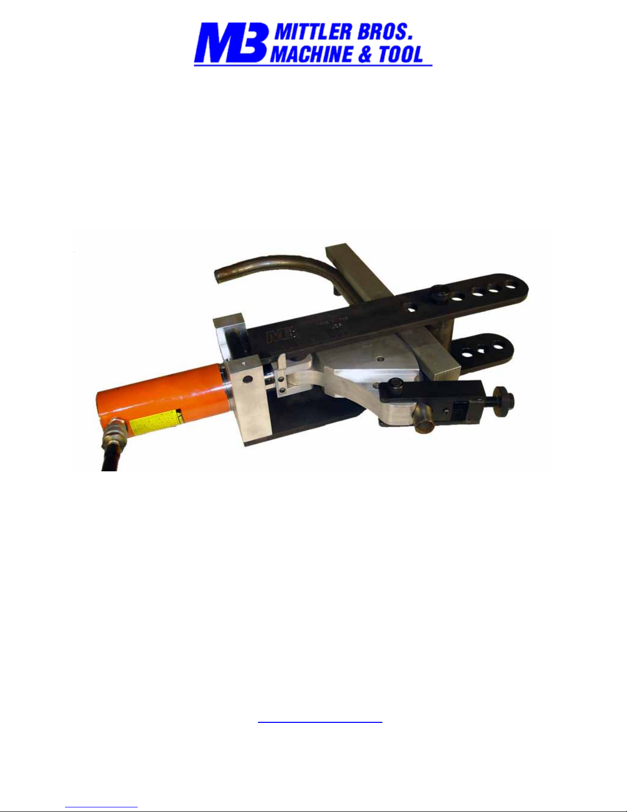
Model # 900
90° Hydraulic Bender
CAUTION: Read and Understand
These Operating, Servicing, and
Safety Instructions, Before Using
This Machine.
1-800-467-2464
10 Cooperative Way Wright City, MO 63390
P.O. Box 110 Foristell, MO 63348
1-636-745-7757 Fax 1-636-745-2874
www.mittlerbros.com
REV 1 March 10 2011
Page 2

• Safety Pg.3
• Hydraulic Safety Pre cautions Pg.4
• Hydraulic System Oper ation Pg.5
• Machine Set up Pg.6
- 2 -
Table of Contents
• Operation Pg.7
• Math Formulas Pg.8-11
• Technical D iagram Pg.12
• Optional Equipment Pg.13-15
• Maintenance Pg.16
Page 3

- 3 -
SAFETY
The purpose of the safety section of this manual is to inform operators and
maintenance personnel of the precautions to be taken while operating or servicing the
machine. The following are a few basic guidelines to follow, but as with any type of
machinery good judgment and a safe attitude should be applied at all times.
1. Always disconnect power, lock-out and tag-out machine per OSHA regulations before
attempting to service this machine.
2. Always wear safety glasses or other approved eye protection while operating or
servicing the machine.
3. Keep all body parts and any foreign objects away from moving parts. Do not reach
into the machine without first disconnecting all power sources.
4. Do not attempt to override any safety device on the machine.
5. Do not operate the machine if it has been damaged or is not operating properly.
6. Do not wear jewelry (watches, rings, necklaces, etc.), or loose fitting clothing while
operating or servicing the machine.
7. The machine should only be operated or serviced by properly trained, authorized
personnel.
8. Replacement parts should have the same specification and operation as the original
parts on the machine.
9. Before starting the machine be sure it is set up properly.
10. The machine and work area should be kept neat and clean.
11. Do not operate or service any machine while under the influence of drugs or alcohol.
NOTE: THESE SAFETY RULES ARE FOR YOUR BENEFIT TO HELP PREVENT INJURY TO
YOURSELF AND/OR YOUR CO-WORKERS. REVIEW ALL SETUP AND OPERATING
PROCEDURES, WHETHER COVERED OR NOT, IN THIS MANUAL TO HELP INSURE SAFE
OPERATION OF THE MACHINE.
Page 4

- 4 -
HYDRAULIC SAFETY PRECAUTIO NS
WARNING
General Operation
• All WARNING statements must be carefully observed to help prevent personal injury.
• Before operating the pump, all hose connections must be tig ht en ed with the proper tools. Do not over
tighten. Connections should only be tightened securely and leak-free. Over tightening can cause
premature thread failure or high pressure fittings to split at pressures lower than their rated capacities.
• Should a hydraulic hose ever rupture, burst, or need to be disconnected, immediately shut off the
pump and release all pressure. Never attempt to grasp a leaking pressurized hose with your hands.
The force of escaping hydraulic fluid could cause serious injury.
• Do not subject the hose to potential hazard such as fire, sharp surfaces, extreme heat or cold or
heavy impact. Do not allow the hose to be altered or kink, twist, curl, crush, cut, or bend so tightly that
the fluid flow within the hose is blocked or reduced. Periodically inspect the hose for wear, because
any of these condition’s can damage the hose and possibly result in personal injury.
• Do not use the hose to move attached equipment. Stress can damage hose and possibly cause
personal injury.
• Hose material and coupler seals must be compatible with the hydraulic fluid used. Hoses also must
not come in contact with corrosive materials such as creosote-impregnated objects and some paints.
Consult the manufacturer before painting a hose. Hose deterioration due to corrosive materials can
result in personal injury. Never paint the couplers.
• Inspect machine for wear, damage, and correct function before each use. Do not use machinery that
is not in proper working order, but repair or replace it as necessary.
• Replace worn or damaged safety decals.
• Modification of a product requires written Power Team authorization.
• Use only components with the same pressure rating when assembling a system or machine.
Pump
• Do not exceed the hydraulic pressure rating noted on the pump data plate or tamper with the internal
high pressure relief valve. Creating pressure beyond the rated pressure can result in personal injury.
• Before replenishing the fluid level, retract the system to prevent overfilling the pump reservoir. An
overfill can cause personal injury due to excess reservoir pressure create when cylinders are
retracted.
Air Supply
• Shut off and disconnect the air supply when the pump is not in use or before breaking any
connections in the system.
PREPARATION & SET-UP
Air Supply Hook-Up
Remove the thread protector from the air inlet of the pump. Select and install the threaded fittings
which are compatible with your air supply fittings. The air supply should be 20 CFM (.57 M3/min.) and
100 PSI (7 BAR) at the pump to obtain the rated hydraulic pressure. Air pressure should be regulated
to a maximum of 140 PSI (9 BAR). Secure your pump fitting to the air supply.
WARNING: If improperly used, pressurized equipment can be potentially hazardous. Therefore:
• Hydraulic connections must be securely fastened before building pressure in the system.
• Release all system pressure before loosening any hydraulic connection in the system.
Venting the Reservoir
To improve hydraulic fluid delivery and increase useable hydraulic fluid capacity, remove shipping
plug and install filler/vent cap before using the pump.
Page 5
- 5 -
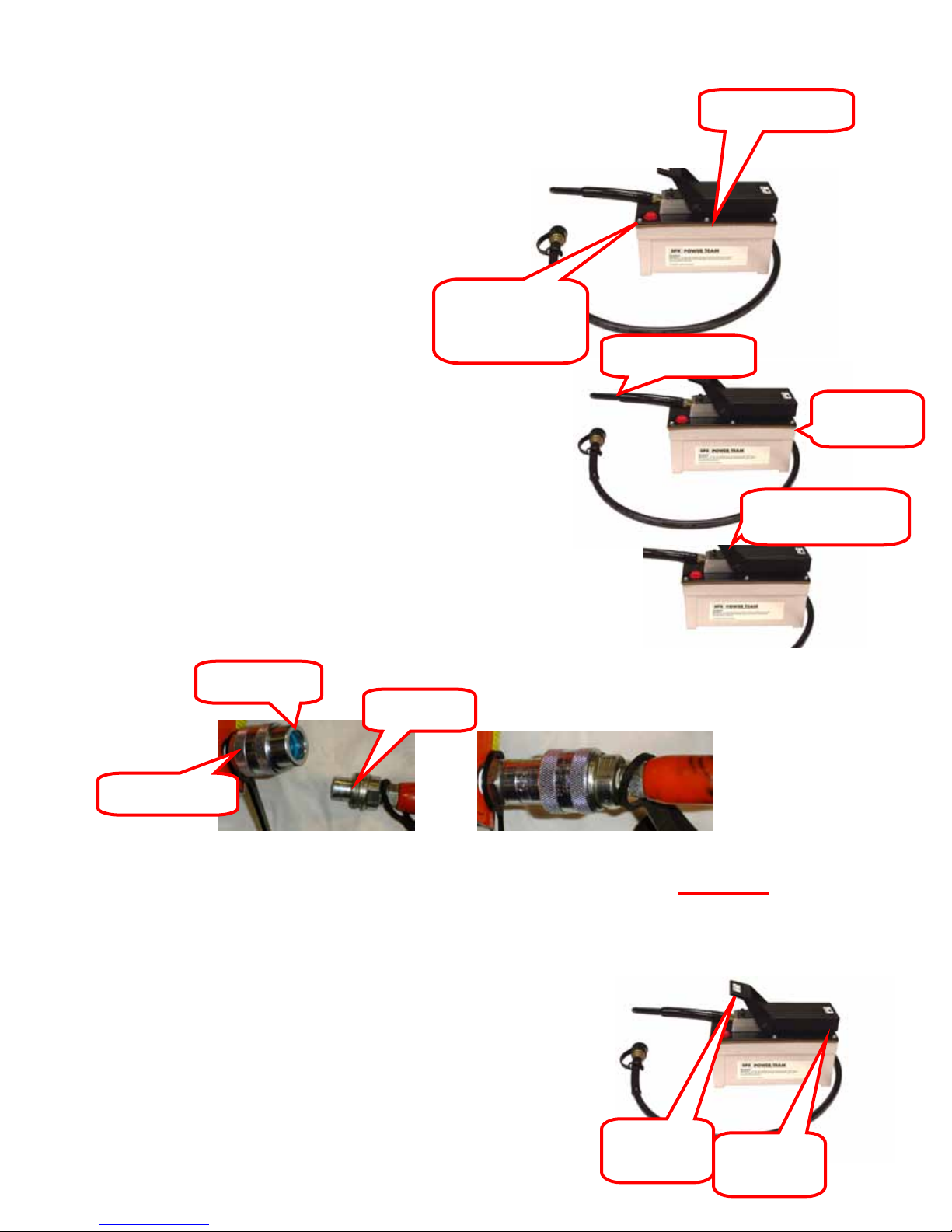
RED Plug should
Pump Assembly
Air
TOE END
HEEL END
Push Down to
Female End
Male End
Retainer Collar
HYDRAULIC SYSTEM
1. Remove the RED Plug in the pump assembly and replace with the
supplied BLACK plug. This is the reservoir venting system
and damage or inoperabilit y may result if not chang ed out.
2. Attach the hydraulic hose to the pump. Be sure to use a
quality thread sealer on both connections
3. Attach an air line fitting for your shop air to other end of the
pump.
be changed to
BLACK Plug
Hydraulic Hose
Connector
Release Pressure
4. Push the pump foot pedal to the release position (TOE END) to
relieve all internal pressure.
5. Push the MALE hose end, from the pump, into the FEMALE
Cylinder fitting.
6. Thread the retainer collar hand tight. NOTE: This procedure will insure that the male & female fittings
positively seat against each other, eliminating any possibility of air locking. CAUTION Failing to follow
this procedure may cause the cylinder to not retract and / or leak.
BLEED THE CYLINDER
7. Connect a compressed air supply (90PSI) to the pump.
8. Elevate the pump and hose above the cylinder.
9. Push the hydraulic pump pedal HEEL END to actuate the
cylinder. Run the cylinder out about half way. Release the pump
by pressing on the TOE END of the pedal. Repeat this process
three or four times or until the ram cylinder movement is smooth.
Retract
Pump
Page 6

#12 Follow Bar
#13 Roller
#10 Saddle
#5 & #8 Clevis Pin
#7 Clevis
#9 & #11 Saddle Pin
#16 Female Hydraulic
#3 & #15 Roller Pin
#4 & #14 Upper Frame
#16
Release
Pump
MACHINE SETUP
Coupler
1. Remove machine from packaging.
- 6 -
2. Place machine on table or floor.
3. Remove roller pin.
4. Rotate upper frame out of the way.
Pressure
5. Remove clevis pin.
6. Remove bender shoe & follow bar from packaging.
7. Insert shoe into clevis.
AIR / HYDRAULIC PUMP
Note: Shoe can be installed to rotate in either direction
to complete the bends.
8. Insert clevis pin.
9. Remove saddle pin from adjustable saddle.
10. Place saddle on to shoe as shown.
11. Insert saddle pin into saddle and shoe.
CAUTION: Be sur e pin is completely through bottom saddle ar m.
12. Place follow bar on to machine as shown.
Pressure
Hydraulic
Coupler
13. Slide roller as close as possible to follow bar.
Note: Lubri cate (oil) rol ler Top / Bottom and I nside Diameter
14. Close the upper frame.
15. Note: Lubricate (oil) Pin Outside Diameter Insert roller pin through the upper
frame, roller, & lower frame.
CAUTION: Be sur e pin is completely through lower frame arm.
16. Machine is now ready for use.
Page 7

- 7 -
#2 Bend Start Point
#3 Tubing Through the Saddle
#4 Roller
Male
Coupler
#9 Release
#4 & #7
AIR / HYDRAULIC PUMP
#5 Shoe Start Point
#8 Reference Scale
#10 Follow Bar
#10 Saddle
#10 Saddle Pin
OPERATION
Pump
Pressure
Pressure
1. Insert tubing into channel in the shoe, follow bar, and
adjustable s addle.
CAUTION: B e sure roll er pin is completely through lower
frame
2. Align the be nd start p oint marked on tubing t o the bend st art
point on th e bender sh oe.
3. Make sure that tubing is sticking all the way through the adjustable
CAUTION: Be sure pin is completely through bottom saddle arm.
saddle.
4. Tighten adj ustable sad dle ”V” bl ock against tubing.
5. Align the fr ont edge of the follo w bar with t he bend star t point of t he bending s hoe.
6. Press the foot pedal on the hydraulic pump, using short bursts until the bending shoe and follow
bar are clos e to the ro ller.
7. Check your tubing to make sure that your tubing start point is still aligned with the shoe start point.
8. Now make your bend by pressing down on the foot pedal heel on the hydraulic unit until the
desired angl e is reached.
9. It usually is nec essary to bend tub ing past the desire d angle a few degre es to account for tubi ng
spring back . Note: Rec ord locatio n of referenc e scale po inter to ref erence sc ale to assist in
completing f uture bend s to same de gree of be nd with sam e tubing material, size, and wall
thickness. T hen you ca n bend the n ext pieces to that sam e referenc e scale m ark.
10. When desir ed angle is r eached, pr ess hydraul ic pump f oot pedal to e to release pressure .
11. Turn adjus table saddl e knob count erclockwis e to remove saddle pin, saddle and follow bar.
12. Repeat thes e steps wi th each add itional be nd.
Hydraulic
Page 8

- 8 -
CORRECTED MATHEMATICAL FORMULA
FOR HYDRAULIC TUBING BENDER
WHEN USING INSTRUCTION VIDEO
The following formula should be used to determine the start point for each required bend.
The example will be for a Double Bevel Bend
L1 = 26 25 degree angle
L2 = 15 65 degree angle
L3 = 39 65 degree angle
L4 = 15 25 degree angle
L5 = 26
Bend #1 Start Point:
L1 – ½ developed length (DL25) – ½ (Gain)
26” – ½ (3.064”) – ½ (.050)
26” – 1.532” - .025” = 24.448
Bend #2 Start Point:
L1 + L2 – Gain 1 – ½ (DL65) – ½ (Gain 2)
26 + 15 - .050 –1/2 (7.941) – ½ (.973”)
26 + 15 - .050 – 3.9705 - .48895 = 36.491
Bend #3 Start Point:
L1 + L2 + L3 – Gain 1 – Gain 2 – ½ (DL65) – ½ (Gain 3)
26 + 15 + 39 - .050” - .978 – ½(7.941) – ½ (.972”)
26 + 15 + 39 - .050” -.978 – 3.9705 - 0. 48 6 = 74.5 15
Bend #4 Start Point:
L1 + L2 + L3 + L4 – Gain 1 – Gain 2 – G ain 3 – ½ (DL25) – ½ (Gain 4)
26 + 15 + 39 + 15 -.050 - .978 - .978 –1/2 (3.054) – ½ (0.497)
26 + 15 + 39 + 15 - .050 - .978 - .978 – 1.527 – 0.025 = 91.442
______________________________________________________________________________________
______________________________________________________________________________________
______________________________________________________________________________________
______________________________________________________________________________________
______________________________________________________________________________________
______________________________________________________________________________________
Page 9

- 9 -
Degree
of Bend
Degree
of Bend
1
.0000
31
.0136
61
.1134
2
.0000
32
.0150
62
.1196
3
.0000
33
.0165
63
.1260
4
.0000
34
.0181
64
.1327
5
.0000
35
.0197
65
.1397
6
.0001
36
.0215
66
.1469
7
.0001
37
.0234
67
.1544
8
.0003
38
.0254
68
.1622
9
.0003
39
.0276
69
.1703
10
.0005
40
.0298
70
.1787
11
.0006
41
.0322
71
.1874
12
.0008
42
.0347
72
.1964
13
.0010
43
.0373
73
.2058
14
.0013
44
.0400
74
.2156
15
.0015
45
.0430
75
.2257
16
.0018
46
.0461
76
.2361
17
.0022
47
.0493
77
.2470
18
.0026
48
.0527
78
.2582
19
.0031
49
.0562
79
.2699
20
.0036
50
.0600
80
.2891
21
.0042
51
.0637
81
.2944
22
.0048
52
.0679
82
.3074
23
.0055
53
.0721
83
.3208
24
.0062
54
.0766
84
.3347
25
.0071
55
.0812
85
.3491
26
.0079
56
.0860
86
.3640
27
.0090
57
.0911
87
.3795
28
.0100
58
.0963
88
.3955
29
.0111
59
.1018
89
.4121
30
.0126
60
.1075
90
.4292
GAIN F ACTORS
Degree of
Bend
Multiplier
Multiplier
Multiplier
GAIN = GAIN FACTOR FOR DEGREE OF BEND X RADIUS
FIND THE GAIN FOR AN 85 DEGREE BEND
GAIN = .3491 X 7 = 2.4437 OR 2 7/16
EXAMPLE:
USING A 7 INCH RADIUS
Page 10

-- 10 --
DEVELOPED LENGTH
DEVELOPED LENGTH = .0175 X DEGREE OF BEND X RADIUS
EXAMPLE:
FIND THE DEVELOPED LENGTH OF A 70 DEGREE
BEND USING AN 8 INCH RADIUS.
DEVELOPED LENGTH = .0175 X 70 X 8 = 9.80 OR 9 13/16
________________________________________________________________________________________
________________________________________________________________________________________
________________________________________________________________________________________
________________________________________________________________________________________
________________________________________________________________________________________
________________________________________________________________________________________
________________________________________________________________________________________
________________________________________________________________________________________
________________________________________________________________________________________
________________________________________________________________________________________
________________________________________________________________________________________
________________________________________________________________________________________
________________________________________________________________________________________
________________________________________________________________________________________
Page 11

-- 11 --
Degree
Bend
Degree
Bend
1
57.30
25
2.37
2
28.65
26
2.28
3
19.11
27
2.20
4
14.33
28
2.13
5
11.47
29
2.06
6
9.57
30
2.00
7
8.21
31
1.94
8
7.18
32
1.89
9
6.39
33
1.84
10
5.76
34
1.79
11
5.24
35
1.74
12
4.81
36
1.70
13
4.45
37
1.66
14
4.13
38
1.62
15
3.86
39
1.59
16
3.63
40
1.56
17
3.42
41
1.52
18
3.24
42
1.49
19
3.07
43
1.46
20
2.92
44
1.44
21
2.79
45
1.41
22
2.67
46
1.39
23
2.56
47
1.37
24
2.46
48
1.35
TABLE FOR OFFSET MULTIPLIER
of
Multiplier
of
Multiplier
DISTANCE BETWEEN BENDS = OFFSET MULTIPLIER FOR
DEGREE X OFFSET HEIGHT
EXAMPLE:
FIND THE DISTANCE BETWEEN BENDS FOR A
15 INCH OFFSET USING 25 DEGREE BENDS.
DISTANCE BETWEEN BENDS = 2.37 X 15 = 35.55 OR 35 9/16
Page 12

-12-
ITEM NO. QTY. PART NO.
1 1
900-003 Cylinder Mount Block
2 1 900-002 Lower Frame
3 1 900-005 Upper Frame
4
1
900-004 Shoe Clevis
5 1 900-007 Follow Bar Roller
6 1
900-018 Scale Pointer
7
1
900-502 Hydraulic Cylinder
8
1
900-008-C Hinge Pin
9 1 900-008-
A Roller Pin
10 1 900-008-B Clevis Pin
11 1 900-006 Clevis Adapter
12 2 05/8-11x1-1/2 Hex Head
13 1 Delrin
14
1
5/16-18x1/4 Set Screw
15 2 1/4-20x1/2 Button Head
16 1 1/4-20x1/4 Set Screw
17 1 Roll Pin
1-800-467-2464 www.mittlerbros.com
5
9
3
8
14
16
13 7 1
6
12
2
15
17
11
10
4
Page 13

-13-
Optional Equipment
Adjustable Saddles for 90 & 180 Hydraul ic Benders
Saddle eliminates the need fo r individual saddles for each tubi ng size. Two sizes
handle 5/8” to 1-3/4” Round & Sq uare Tubing.
• Easy Release “V” Block eliminates Stuck Saddle from tube spring back
• Securely holds each tube, eliminates tube creep
• Easier Bend-to-Bend Alignment with light pressure on tube
2500-300
2500-301
2500-302
Advantages
Adjustable Saddle, Small 5/8" t o 1-3/8"
Adjustable Saddle, Medium 1-1/2 to 1-3/4
Adjustable Saddle, Large 2" OD
Pumps
900-504-6 Air Hydraulic Pump, 6' Hose & Fitting
900-508-6 Electric Hydraulic Pump, Hose & Fittings 6'
900-D Digital Read Out for 90° Hydraulic Tube Bender
900-500-DVD Tubing Bending DVD for 90 Degree Hydraulic Tube Bender
Page 14

-14-
Bend Protractors
2100-4 4" Protractor Assembly
2100-5 5" Protractor Assembly
2100-6
2100-7 7" Protractor Assembly
2100-8 8" Protractor Assembly
2100 4" Thru 8" Protractor Set
6" Protractor Assembly
Page 15

-15-
BEND-TECH EZ
Designed for simple 2d parts!
900-510 Bend-Tech EZ Software
BEND-TECH EZ-3D
Designed for 3d bending, with 360 d egree part rotation!
900-511 Bend-Tech EZ-3D Software
BEND-TECH PRO
Full 3d Assembly & Manufacturing I nstructions, plus all EZ featur es!
900-512 Bend-Tech Pro Software
900-513 Bend-Tech SE Software
Page 16

-16-
Air Hydraulic Pump
Electric Hydraulic Pump
The fluid level should be 1/2 inch (12.7 mm) from the filler /
vent cap with all cylinders retracted.
The fluid level should be 1-3/4 inch (44.5 mm) from the filler /
vent cap with all cylinders retracted.
SPX Power Team
Enerpac
Mobil DTE 24 Hydraulic Oil is Compatible with Enerpac Components
MAINTENANCE
Inspecting The Hydraulic Fluid Level
Check the fluid level in the reservoir after every 10 hours of use. Drain and replenish the reservoir with Power Team
hydraulic fluid after every 300 hours of use approximately.
For pumps with a 105 cubic inch (1.71) reservoir capacity
For Machines With:
Orange & White Cylinder with Black Letters
White & Black Pump
Use: AW 46 - Non Foaming Hydraulic Fluid
or
Flame Out # 220 Fire Resistant Hydraulic Fluid
Refilling The Reservoir
If additional fluid must be added to reservoir, use only manufacturer suggested hydraulic fluid.
Clean the entire area around the filler plug before adding fluid to the reservoir.
Remove the filler plug and insert a clean funnel with filter.
The cylinder must be fully retracted and the air supply disconnected when adding the fluid to the reservoir.
For pumps with a 2 gallon (7.61) reservoir capacity
Yellow Cylinder with Black Letters
Yellow & Black Pump
Use: ISO 7 HF 101 Gal
or
ISO 32 HF 100 Qt.
or
 Loading...