

MB 738 Service manual

Model J
(Machine Code: G060)
SERVICE MANUAL
July 30th, 2001
Subject to change

!
IMPORTANT SAFETY NOTICES
PREVENTION OF PHYSICAL INJURY
1. Before disassembling or assembling parts of the printer and peripherals,
make sure that the printer power cord is unplugged.
2. The wall outlet should be near the printer and easily accessible.
3. If any adjustment or operation check has to be made with exterior covers off
or open while the main switch is turned on, keep hands away from electrified
or mechanically driven components.
4. The printer drives some of its components when it completes the warm-up
period. Be careful to keep hands away from the mechanical and electrical
components as the printer starts operation.
5. The inside and the metal parts of the fusing unit become extremely hot while
the printer is operating. Be careful to avoid touching those components with
your bare hands.
HEALTH SAFETY CONDITIONS
Toner and developer are non-toxic, but if you get either of them in your eyes by
accident, it may cause temporary eye discomfort. Try to remove with eye drops
or flush with water as first aid. If unsuccessful, get medical attention.
OBSERVANCE OF ELECTRICAL SAFETY STANDARDS
1. The printer and its peripherals must be serviced by a customer service
representative who has completed the training course on those models.
2. The NVRAM module (option) installed on the controller has a lithium battery
which can explode if replaced incorrectly. Replace the NVRAM only with an
identical one. The manufacturer recommends replacing the entire NVRAM.
Do not recharge or burn this battery. Used NVRAM must be handled in
accordance with local regulations.
3. The optional fax and memory expansion units contain lithium batteries,
which can explode if replaced incorrectly. Replace only with the same or an
equivalent type recommended by the manufacturer. Do not recharge or burn
the batteries. Used batteries must be handled in accordance with local
regulations.
SAFETY AND ECOLOGICAL NOTES FOR DISPOSAL
1. Do not incinerate toner bottles or used toner. Toner dust may ignite suddenly
when exposed to an open flame.
2. Dispose of used toner, the maintenance unit which includes developer or the
organic photoconductor in accordance with local regulations. (These are
non-toxic supplies.)
3. Dispose of replaced parts in accordance with local regulations.
When keepi ng used lithium batteries in order to dispose of th em later, do not
put more than 100 batteries per sealed box. Storing larger numbers or not
sealing them apart may lead to chemical reactions and heat build-up.
4. When keeping used lith iu m batteries in order to dispose of them later, do not
put more than 100 batteries per sealed box. Storing larger numbers or not
sealing them apart may lead to chemical reactions and heat build-up.
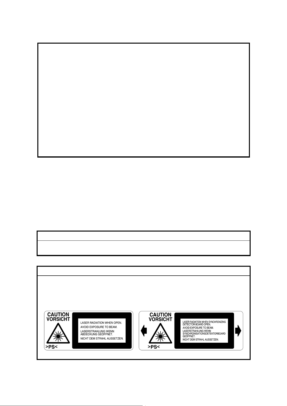
LASER SAFETY
The Center for Devices and Radiological Health (CDRH) prohibits the repair of
laser-based optical units in the field. The optical housing unit can only be repaired
in a factory or at a location with the requisite equipment. The laser subsystem is
replaceable in the field by a qualified Customer Engineer. The laser chassis is not
repairable in the field. Customer engineers are therefore directed to return all
chassis and laser subsystems to the factory or service depot when replacement of
the optical subsystem is required.
!
WARNING
Use of controls, or adjustment, or performance of procedures other than
those specified in this manual may result in hazardous radiation exposure.
!
WARNING
WARNING: Turn off the main switch before atte mpting any of the
procedures in the Laser Optics Housing Unit section. Laser
beams can seriously damage your eyes.
CAUTION MARKING:

Trademarks
Microsoft®, Windows®, and MS-DOS® are registered trademarks of Microsoft
Corporation in the United States and /or other countries.
PostScript® is a registered trademark of Adobe Systems, Incorporated.
PCL® is a registered trademark of Hewlett-Packard Company.
Ethernet® is a registered trademark of Xerox Corporation.
PowerPC® is a registered trademark of International Business Machines
Corporation.
Other product names used herein are for identification purposes only and may be
trademarks of their respective companies. We disclaim any and all rights involved
with those marks.

TABLE OF CONTENTS
1 INSTALLATION ........................................................................... 1-1
1.1 INSTALLATION REQUIREMENTS...........................................................1-1
1.1.1 ENVIRONMENT...............................................................................1-1
1.1.2 MACHINE LEVEL.............................................................................1-1
1.1.3 MACHINE SPACE REQUIREMENT.................................................1-2
1.1.4 POWER REQUIREMENTS..............................................................1-2
1.2 OPTIONAL UNIT COMBINATIONS ..........................................................1-3
1.3 INSTALLATION FLOW CHART................................................................1-4
1.4 MACHINE INSTALLATION .......................................................................1-5
1.5 OPTIONAL UNIT INSTALLATION.............................................................1-7
1.5.1 LIST OF OPTIONS...........................................................................1-7
Note for Transporting the Machine .......................................................1-7
1.5.2 PUNCH UNIT INSTALLATION.........................................................1-8
Accessory Check..................................................................................1-8
Installation Procedure...........................................................................1-9
2 PREVENTIVE MAINTENANCE.................................................... 2-1
2.1 USER MAINTENANCE .............................................................................2-1
2.2 SERVICE MAINTENANCE........................................................................2-3
3 REPLACEMENT AND ADJUSTMENT......................................... 3-1
3.1 SPECIAL TOOLS......................................................................................3-1
3.2 IMAGE ADJUSTMENT..............................................................................3-2
3.2.1 REGISTRATION...............................................................................3-2
Image Area...........................................................................................3-2
Leading Edge........................................................................................3-2
Side to Side ..........................................................................................3-2
Adjustment Standard............................................................................3-2
Paper Registration Standard.................................................................3-2
1st side .................................................................................................3-2
2nd side in duplex .................................................................................3-2
Adjustment Procedure ..........................................................................3-3
3.2.2 COLOR REGISTRATION.................................................................3-3
Line Position Adjustment......................................................................3-3
Adjustment for Line Speed of Fusing Unit.............................................3-3
3.2.3 PRINTER GAMMA...........................................................................3-4
Adjustment Overview............................................................................3-4
Adjustment Procedure ..........................................................................3-4
3.3 EXTERIOR COVERS................................................................................3-5
3.3.1 REAR COVER AND UPPER REAR COVER ...................................3-5
3.3.2 PAPER EXIT TRAY..........................................................................3-5
3.3.3 UPPER RIGHT COVER...................................................................3-5
3.3.4 FRONT COVER ............................................................................... 3-6
3.3.5 LEFT COVER AND REAR LEFT COVER........................................ 3-6
3.3.6 UPPER LEFT COVER AND OPERATION PANEL ..........................3-7
i

3.4 LASER OPTICS........................................................................................3-8
3.4.1 CAUTION DECAL LOCATIONS.......................................................3-8
3.4.2 LASER OPTICS HOUSING UNIT ....................................................3-9
Adjustments after Replacing the Laser Optics Housing Unit...............3-11
3.4.3 POLYGON MIRROR MOTOR........................................................3-12
3.4.4 LASER SYNCHRONIZING DETECTOR BOARDS........................3-12
3.5 PCU AND DEVELOPMENT UNIT...........................................................3-13
3.6 PAPER FEED..........................................................................................3-14
3.6.1 PICK-UP, FEED, AND SEPARATION ROLLERS ..........................3-14
Tray 1 and Tray 2 ...............................................................................3-14
By-pass Tray.......................................................................................3-14
3.6.2 PAPER WIDTH DETECTION BOARD...........................................3-15
3.6.3 VERTICAL TRANSPORT SENSOR...............................................3-15
3.6.4 RIGHT DOOR UNIT.......................................................................3-16
3.6.5 REGISTRATION SENSOR AND RELAY SENSOR.......................3-17
3.6.6 PAPER FEED CLUTCHES............................................................. 3-17
3.6.7 BY-PASS FEED CLUTCH..............................................................3-18
3.6.8 TRAY LIFT MOTOR.......................................................................3-18
3.7 TRANSFER AND PAPER TRANSPORT UNIT.......................................3-19
3.7.1 TRANSFER UNIT...........................................................................3-19
3.7.2 TRANSFER BELT CLEANING UNIT..............................................3-21
3.7.3 CLEANING BLADE AND CLEANING ROLLER .............................3-22
3.7.4 TRANSFER BELT ..........................................................................3-23
3.7.5 OTHERS.........................................................................................3-27
Front Plate..........................................................................................3-27
Grounding Spring................................................................................3-27
Drive Gear and Left Drive Roller.........................................................3-27
3.8 FUSING...................................................................................................3-28
3.8.1 FUSING UNIT.................................................................................3-28
3.8.2 OIL SUPPLY UNIT.........................................................................3-29
3.8.3 UPPER COVER .............................................................................3-29
3.8.4 FUSING BELT UNIT.......................................................................3-30
3.8.5 PRESSURE ROLLER.....................................................................3-33
3.8.6 PAPER EXIT ..................................................................................3-35
3.9 ELECTRICAL COMPONENTS................................................................3-36
3.9.1 MOVING THE CONTROLLER BOX OUT OF THE WAY...............3-36
3.9.2 MOVING THE HIGH VOLTAGE SUPPLY UNIT -
C, B OUT OF THE WAY.................................................................3-36
3.9.3 CONTROLLER AND BCU..............................................................3-37
3.9.4 NVRAM REPLACEMENT PROCEDURE.......................................3-38
NVRAM for BCU................................................................................. 3-38
NVRAM for Controller.........................................................................3-38
NVRAMs for both BCU and Controller................................................3-38
3.9.5 REMOVING THE HIGH VOLTAGE SUPPLY BOARD - C, B.........3-39
3.9.6 PSU................................................................................................3-39
3.10 DRIVE UNIT..........................................................................................3-40
3.10.1 REGISTRATION CLUTCH...........................................................3-40
DEVELOPMENT CLUTCHES ............................................................3-41
3.10.3 DEVELOPMENT DRIVE MOTOR - CMY.....................................3-42
ii

3.10.4 DRUM DRIVE MOTOR - CMY AND
DRUM DRIVE MOTOR - K...........................................................3-43
DEVELOPMENT DRIVE MOTOR - K.................................................3-44
4 TROUBLESHOOTING ................................................................. 4-1
4.1 PROCESS CONTROL ERROR CONDITIONS.........................................4-1
4.1.1 DEVELOPER INITIALIZATION RESULT.........................................4-1
4.1.2 PROCESS CONTROL SELF-CHECK RESULT...............................4-3
4.1.3 LINE POSITION ADJUSTMENT RESULT .......................................4-4
4.2 SERVICE CALL CONDITIONS.................................................................4-7
4.2.1 SUMMARY.......................................................................................4-7
SC Classification...................................................................................4-7
4.3 SC TABLE.................................................................................................4-9
4.4 TROUBLESHOOTING GUIDE................................................................4-33
4.4.1 IMAGE QUALITY............................................................................4-33
4.4.2 COLOR SHIFT ...............................................................................4-37
Adjustment Standard: Max. 200 µm...................................................4-39
Preparation.........................................................................................4-39
How to measure the gap between color lines.....................................4-44
4.4.3 COLOR SHIFT AFTER TRANSFER UNIT REPLACEMENT .........4-46
Check the color shift level...................................................................4-46
Fusing/ Registration Roller Speed Adjustment ...................................4-46
SP mode (sub-scan registration) reset................................................4-46
Transfer belt aging..............................................................................4-46
Fusing roller speed adjustment...........................................................4-47
Registration roller speed adjustment (for color mode)........................4-47
Line position fine adjustment for sub-scan..........................................4-47
Registration roller speed adjustment (For B&W mode).......................4-48
4.5 ELECTRICAL COMPONENT DEFECTS ................................................4-49
4.5.1 SENSORS......................................................................................4-49
4.6 BLOWN FUSE CONDITIONS.................................................................4-50
4.7 LEDS (BCU)............................................................................................4-50
5 SERVICE TABLES....................................................................... 5-1
5.1 SERVICE PROGRAM MODE....................................................................5-1
5.1.1 ENABLING AND DISABLING SERVICE PROGRAM MODE...........5-1
Entering the Service Mode....................................................................5-1
Accessing the Required Program.........................................................5-2
Inputting a Value or Setting for a Service Program ...............................5-2
Exiting Service Mode............................................................................5-2
5.2 PRINTER CONTROLLER SERVICE MODE.............................................5-3
5.2.1 REMARKS........................................................................................5-3
Display on the Control Panel Screen....................................................5-3
Others...................................................................................................5-4
5.2.2 SERVICE MODE MENU (“1. SERVICE”).........................................5-5
5.2.3 BIT SWITCH PROGRAMMING........................................................5-6
5.3 PRINTER ENGINE SERVICE MODE........................................................5-7
5.3.1 SERVICE MODE TABLE (“2. ENGINE”) ..........................................5-7
SP1-XXX (Feed)...................................................................................5-7
iii

SP2-XXX (Drum).................................................................................5-13
SP3-XXX (Process) ............................................................................5-23
SP5-XXX (Mode) ................................................................................5-30
SP6-XXX (Peripherals).......................................................................5-38
SP7-XXX (Data Log)...........................................................................5-39
5.3.2 INPUT CHECK TABLE...................................................................5-47
Table 1: Paper Height Sensor.............................................................5-49
Table 2: Paper Size Switch (Tray 2)...................................................5-49
Table 3: Paper Size (By-pass Table)..................................................5-49
5.3.3 OUTPUT CHECK TABLE...............................................................5-50
5.3.4 TEST PATTERN (SP5-997)...........................................................5-54
5.4 FIRMWARE UPDATE PROCEDURE......................................................5-55
5.4.1 TYPE OF FIRMWARE....................................................................5-55
5.4.2 ERROR RECOVERY......................................................................5-55
Engine Firmware/Controller NIB Firmware .........................................5-55
Controller System Firmware: ..............................................................5-55
5.4.3 CONTROLLER/ENGINE FIRMWARE UPGRADE .........................5-56
5.5 CONTROLLER SELF-DIAGNOSTICS....................................................5-57
5.5.1 OVERVIEW....................................................................................5-57
5.5.2 DETAILED SELF-DIAGNOSTICS..................................................5-58
5.6 USER PROGRAM MODE.......................................................................5-59
5.7 DIP SWITCHES.......................................................................................5-60
Controller Board..................................................................................5-60
6 DETAILED SECTION DESCRIPTIONS ....................................... 6-1
6.1 OVERVIEW...............................................................................................6-1
6.1.1 COMPONENT LAYOUT...................................................................6-1
6.1.2 PAPER PATH...................................................................................6-2
6.1.3 DRIVE LAYOUT...............................................................................6-3
6.1.4 BOARD STRUCTURE...................................................................... 6-4
Overview...............................................................................................6-4
Descriptions..........................................................................................6-5
6.1.5 PRINTING PROCESS......................................................................6-6
6.2 PROCESS CONTROL ..............................................................................6-8
6.2.1 OVERVIEW......................................................................................6-8
6.2.2 POTENTIAL CONTROL...................................................................6-8
Overview...............................................................................................6-8
Process Control Self Check..................................................................6-9
6.2.3 PROCESS CONTROL SELF CHECK PROCEDURE....................6-10
Step 1: VSG Adjustment......................................................................6-10
Step 2: ID Sensor Solid Pattern Generation .......................................6-11
Step 3: Sensor Pattern Detection .......................................................6-11
Step 4: Toner Amount Calculation......................................................6-11
Step 5: VD, VB, VL Selection and V
Step 6: ID Sensor Highlight Pattern Generation .................................6-12
Step 7: Sensor Pattern Density Detection...........................................6-12
Step 8: VL (LD Power) Selection.........................................................6-13
6.2.4 TONER SUPPLY CONTROL .........................................................6-14
Overview.............................................................................................6-14
Adjustment............................6-11
REF
iv

Toner Supply Control Modes..............................................................6-14
6.2.5 TONER NEAR END/TONER END DETECTION............................6-15
Introduction.........................................................................................6-15
Toner Near End Detection..................................................................6-15
Toner End Detection...........................................................................6-15
Toner End Recovery...........................................................................6-15
6.2.6 DEVELOPER INITIALIZATION ......................................................6-16
6.3 LASER EXPOSURE................................................................................6-17
6.3.1 OVERVIEW....................................................................................6-17
6.3.2 OPTICAL PATH..............................................................................6-18
6.3.3 LASER SYNCHRONIZING DETECTOR........................................6-19
Overview.............................................................................................6-19
Main Scan Start Detection..................................................................6-19
Clock Frequency Adjustment..............................................................6-19
6.3.4 DUAL BEAM WRITING..................................................................6-20
Dual Beam Mechanism.......................................................................6-20
Laser Beam Pitch Change Mechanism...............................................6-20
6.3.5 LD SAFETY SWITCH.....................................................................6-21
6.3.6 AUTOMATIC LINE POSITION ADJUSTMENTS............................6-22
Overview.............................................................................................6-22
Sub Scan Line Position for YCM.........................................................6-23
Main Scan Line Position for KYCM.....................................................6-23
Magnification Adjustment....................................................................6-23
Main Scan Skew Adjustment.............................................................. 6-24
6.4 PHOTOCONDUCTOR UNIT...................................................................6-25
6.4.1 OVERVIEW....................................................................................6-25
6.4.2 DRIVE.............................................................................................6-26
6.4.3 DRUM CHARGE AND QUENCHING.............................................6-27
6.4.4 DRUM CLEANING..........................................................................6-28
6.4.5 WASTE TONER COLLECTION .....................................................6-29
6.4.6 WASTE TONER BOTTLE FULL DETECTION...............................6-30
6.4.7 PCU DETECTION (DEVELOPMENT UNIT DETECTION).............6-31
6.5 DEVELOPMENT.....................................................................................6-32
6.5.1 OVERVIEW....................................................................................6-32
6.5.2 DRIVE.............................................................................................6-33
6.5.3 DEVELOPER AGITATION.............................................................6-34
6.5.4 DEVELOPMENT BIAS...................................................................6-35
6.5.5 DEVELOPMENT UNIT DETECTION..............................................6-35
6.5.6 TONER SUPPLY MECHANISM.....................................................6-36
Overview.............................................................................................6-36
Toner Agitation ...................................................................................6-36
Toner Transport..................................................................................6-37
6.5.7 TONER CARTRIDGE DETECTION...............................................6-38
6.6 PAPER FEED..........................................................................................6-39
6.6.1 OVERVIEW....................................................................................6-39
6.6.2 DRIVE – TRAYS 1 AND 2..............................................................6-40
6.6.3 PAPER LIFT – TRAYS 1 & 2..........................................................6-41
6.6.4 PAPER SIZE DETECTION – TRAYS 1 & 2....................................6-42
6.6.5 PAPER HEIGHT DETECTION – TRAYS 1 & 2..............................6-43
v

6.6.6 PAPER END DETECTION – TRAYS 1 & 2....................................6-43
6.6.7 REGISTRATION.............................................................................6-44
6.6.8 PAPER FEED LINE SPEED...........................................................6-45
6.6.9 BY-PASS TRAY..............................................................................6-46
6.7 IMAGE TRANSFER AND PAPER SEPARATION...................................6-47
6.7.1 OVERVIEW....................................................................................6-47
6.7.2 TRANSFER BELT DRIVE ..............................................................6-48
6.7.3 TRANSFER AND CLEANING CURRENT......................................6-49
6.7.4 TRANSFER BELT CLEANING.......................................................6-50
6.7.5 TRANSFER BELT CONTACT........................................................6-51
Mechanism .........................................................................................6-51
ACS (Auto Color Sensing) Mode........................................................6-52
6.8 FUSING...................................................................................................6-53
6.8.1 OVERVIEW....................................................................................6-53
6.8.2 FUSING UNIT DRIVE.....................................................................6-54
6.8.3 FUSING TEMPERATURE CONTROL............................................6-55
Fusing Temperatures..........................................................................6-55
Temperature Corrections....................................................................6-56
Overheat Protection............................................................................6-56
6.8.4 OIL SUPPLY AND CLEANING.......................................................6-57
6.8.5 NEW FUSING OIL SUPPLY UNIT DETECTION............................6-58
6.8.6 NEW FUSING UNIT DETECTION..................................................6-59
6.8.7 ENERGY SAVER MODE................................................................6-60
Level 1 Energy Saver Mode................................................................6-60
Level 2 Energy Saver Mode................................................................6-60
6.9 PAPER EXIT...........................................................................................6-61
6.9.1 OVERVIEW....................................................................................6-61
6.9.2 PAPER OVERFLOW DETECTION ................................................6-62
6.10 CONTROLLER......................................................................................6-63
6.10.1 OVERVIEW..................................................................................6-63
6.10.2 BOARD LAYOUT..........................................................................6-65
6.10.3 PRINT DATA PROCESSING .......................................................6-66
RPCS Driver.......................................................................................6-66
PCL5c Driver ......................................................................................6-66
PS3 Driver ..........................................................................................6-67
CMS (Color Management System)..................................................... 6-67
Gray Correction ..................................................................................6-67
BG/UCR (Black Generation/Under Color Removal)............................6-67
Gamma Correction .............................................................................6-67
Toner Limitation..................................................................................6-68
Dither Processing and ROP/RIP.........................................................6-68
6.10.4 CONTROLLER FUNCTIONS.......................................................6-69
Sample Print.......................................................................................6-69
Locked Print........................................................................................6-69
Paper Source Selection......................................................................6-70
Tray Priority (Auto Tray Select)...........................................................6-70
Tray Lock............................................................................................6-70
Manual Tray Select.............................................................................6-70
Auto Continue.....................................................................................6-71
vi

Overview.............................................................................................6-71
Auto Tray Select.................................................................................6-71
Manual Tray Select.............................................................................6-71
Paper Output Tray..............................................................................6-72
Output Tray Selected..........................................................................6-72
Sequential Stacking............................................................................6-72
Stapling...............................................................................................6-73
Punching .............................................................................................6-73
6.11 IEEE1394 INTERFACE.........................................................................6-74
6.11.1 SPECIFICATIONS........................................................................6-74
Hardware Specification.......................................................................6-74
System Requirements.........................................................................6-74
6.11.2 IEEE1394 .....................................................................................6-74
6.11.3 BLOCK DIAGRAM........................................................................6-75
6.11.4 PIN ASSIGNMENT.......................................................................6-75
6.11.5 REMARKS ABOUT THIS INTERFACE KIT..................................6-76
6.11.6 TROUBLESHOOTING NOTES....................................................6-76
PERIPHERALS
DUPLEX UNIT (Machine Code: G571)
1 REPLACEMENT AND ADJUSTMENT...................................G571-1
1.1 DUPLEX INVERTER UNIT.................................................................G571-1
1.1.1 TOP COVER .............................................................................G571-1
1.1.2 DUPLEX CONTROL BOARD....................................................G571-1
1.1.3 DUPLEX INVERTER MOTOR 1................................................G571-2
1.1.4 DUPLEX INVERTER MOTOR 2 AND SWITCH........................G571-2
1.1.5 EXIT SENSOR 3 AND DUPLEX INVERTER SENSOR.............G571-3
1.1.6 EXIT SENSOR 1 AND 2............................................................G571-3
1.2 DUPLEX FEED UNIT.........................................................................G571-4
1.2.1 DUPLEX DRIVE BOARD...........................................................G571-4
1.2.2 DUPLEX FEED MOTOR...........................................................G571-4
1.2.3 DUPLEX FEED SENSOR..........................................................G571-5
2 DETAILED DESCRIPTIONS..................................................G571-6
2.1 OVERVIEW........................................................................................G571-6
2.2 DUPLEX OPERATION.......................................................................G571-7
2.2.1 UP TO A4/LT(8
2.2.2 LARGER THAN A4/LT(8
2.3 DUPLEX INVERTER UNIT.................................................................G571-8
2.3.1 DRIVE........................................................................................G571-8
2.3.2 FEED TO EXTERNAL EXIT TRAY (NON-DUPLEX MODE).....G571-9
2.3.3 FEED TO DUPLEX FEED UNIT..............................................G571-10
2.3.4 FEED TO TWO-TRAY FINISHER...........................................G571-11
With Optional One-Tray Paper Feed Unit....................................G571-11
" X 11") LEF..................................................G571-7
1/2
" X 11") LEF....................................G571-7
1/2
vii

With Optional LCT or Two-Tray Paper Feed Unit........................G571-11
2.4 DUPLEX FEED UNIT.......................................................................G571-12
2.4.1 DRIVE......................................................................................G571-12
2.4.2 FEED-IN AND FEED-OUT ......................................................G571-12
ONE-TRAY PAPER FEED UNIT (Machine Code: G567)
1 REPLACEMENT AND ADJUSTMENT...................................G567-1
1.1 COVER REPLACEMENT...................................................................G567-1
1.2 ROLLER REPLACEMENT .................................................................G567-2
1.2.1 PAPER FEED, SEPARATION, AND PICK-UP ROLLERS........G567-2
1.3 PAPER FEED MOTOR AND MAIN BOARD......................................G567-3
1.4 TRAY LIFT MOTOR...........................................................................G567-4
1.5 PAPER FEED CLUTCH.....................................................................G567-4
1.6 PAPER FEED UNIT REPLACEMENT................................................G567-5
2 DETAILED DESCRIPTIONS..................................................G567-6
2.1 OVERVIEW........................................................................................G567-6
2.1.1 MECHANICAL COMPONENT LAYOUT....................................G567-6
2.1.2 ELECTRICAL COMPONENT LAYOUT.....................................G567-7
2.1.3 DRIVE LAYOUT........................................................................G567-8
TWO-TRAY PAPER FEED UNIT (Machine Code: G568)
1 REPLACEMENT AND ADJUSTMENT...................................G568-1
1.1 COVER REPLACEMENT...................................................................G568-1
1.2 ROLLER REPLACEMENT .................................................................G568-2
1.2.1 PAPER FEED, SEPARATION, AND PICK-UP ROLLERS........G568-2
1.3 PAPER FEED MOTOR AND MAIN BOARD......................................G568-3
1.4 TRAY LIFT MOTORS.........................................................................G568-4
1.5 PAPER FEED CLUTCHES ................................................................G568-4
1.6 PAPER FEED UNIT REPLACEMENT................................................G568-5
2 DETAILED DESCRIPTIONS..................................................G568-6
2.1 OVERVIEW........................................................................................G568-6
2.1.1 MECHANICAL COMPONENT LAYOUT....................................G568-6
2.1.2 ELECTRICAL COMPONENT LAYOUT.....................................G568-7
2.1.3 DRIVE LAYOUT........................................................................G568-8
LARGE CAPACITY TRAY (Machine Code: G569)
1 REPLACEMENT AND ADJUSTMENT...................................G569-1
71.1 DETACHING THE TRAY FROM THE MAINFRAME........................G569-1
1.2 REAR FENCE HP SENSOR..............................................................G569-1
viii

1.3 CHANGING THE TRAY PAPER SIZE ...............................................G569-2
1.4 LEFT TRAY PAPER END SENSOR ..................................................G569-3
1.5 TRAY LIFT MOTOR...........................................................................G569-4
1.6 TRAY MOTOR AND STACK TRANSPORT CLUTCH........................G569-5
1.7 PAPER FEED CLUTCH.....................................................................G569-6
1.8 PAPER FEED UNIT...........................................................................G569-7
1.9 UPPER LIMIT, RIGHT TRAY PAPER END,
AND RELAY SENSORS.....................................................................G569-8
1.10 PICK-UP/PAPER FEED/SEPARATION ROLLER............................G569-9
2 DETAILED SECTION DESCRIPTIONS ...............................G569-10
2.1 OVERVIEW......................................................................................G569-10
2.1.1 MECHANICAL COMPONENT LAYOUT..................................G569-10
2.1.2 ELECTRICAL COMPONENT LAYOUT...................................G569-11
2.2 PAPER FEED...................................................................................G569-12
2.3 SEPARATION ROLLER AND PICK-UP ROLLER RELEASE ..........G569-13
2.4 TRAY LIFT .......................................................................................G569-14
2.5 NEAR END/END DETECTION.........................................................G569-15
2.6 PAPER STACK TRANSPORT MECHANISM...................................G569-16
2.7 RIGHT TRAY PAPER END DETECTION ........................................G569-17
TWO-TRAY FINISHER (Machine Code: G565)
1 REPLACEMENT AND ADJUSTMENT...................................G565-1
1.1 COVERS............................................................................................G565-1
1.1.1 EXTERNAL COVERS................................................................G565-1
1.1.2 INNER COVER..........................................................................G565-1
1.2 POSITIONING ROLLER.....................................................................G565-2
1.3 TRAY 1 EXIT SENSOR......................................................................G565-2
1.4 ENTRANCE SENSOR/STAPLER TRAY ENTRANCE SENSOR.......G565-3
1.5 STAPLER TRAY.................................................................................G565-3
1.6 UPPER STACK HEIGHT SENSORS/
TRAY 1 UPPER LIMIT SWITCH........................................................G565-4
1.7 EXIT GUIDE PLATE MOTOR.............................................................G565-5
1.8 LIFT MOTORS...................................................................................G565-5
1.9 LOWER EXIT SENSOR.....................................................................G565-7
1.10 LOWER STACK HEIGHT SENSORS ..............................................G565-8
1.11 TRAY 2 SHUNT POSITION SENSOR .............................................G565-8
1.12 STAPLER UNIT................................................................................G565-9
1.13 STAPLER ROTATION HP SENSOR................................................G565-9
1.14 TRAY 1 INTERIOR.........................................................................G565-10
1.14.1 TRAY 1 COVERS..................................................................G565-10
tray Shift Sensors and tray release sensor..................................G565-11
1.14.3 TRAY 1 SHIFT MOTOR ........................................................G565-11
1.14.4 BACK FENCE LOCK CLUTCH .............................................G565-11
1.15 FINISHER MAIN BOARD...............................................................G565-12
1.16 PUNCH HOLE POSITION ADJUSTMENT.....................................G565-12
ix

2 TROUBLESHOOTING .........................................................G565-13
2.1 JAM DETECTION.............................................................................G565-13
3 SERVICE TABLES...............................................................G565-14
3.1 DIP SWITCH SETTINGS .................................................................G565-14
3.2 TEST POINTS..................................................................................G565-14
3.3 FUSES .............................................................................................G565-14
4 DETAILED DESCRIPTIONS................................................G565-15
4.1 GENERAL LAYOUT.........................................................................G565-15
4.2 DRIVE LAYOUT...............................................................................G565-16
4.3 JUNCTION GATES..........................................................................G565-17
4.4 TRAY SHIFTING..............................................................................G565-18
4.4.1 TRAY SHIFT MECHANISMS ..................................................G565-18
Tray 1 (Upper Tray).....................................................................G565-18
Tray 2 (Lower Tray).....................................................................G565-19
4.5 TRAY UP/DOWN MECHANISMS....................................................G565-20
4.5.1 TRAY 1....................................................................................G565-20
Introduction..................................................................................G565-20
Normal and sort/stack modes......................................................G565-20
Staple Mode.................................................................................G565-21
Tray 1 release mechanism...........................................................G565-22
4.5.2 TRAY 2....................................................................................G565-23
4.5.3 PRE-STACK MECHANISM.....................................................G565-24
4.6 JOGGER UNIT PAPER POSITIONING MECHANISM.....................G565-25
Vertical Paper Alignment.............................................................G565-25
Horizontal Paper Alignment.........................................................G565-25
4.7 STAPLER MECHANISM..................................................................G565-26
4.7.1 STAPLER MOVEMENT...........................................................G565-26
Stapler Rotation...........................................................................G565-26
Side-to-Side Movement...............................................................G565-26
4.7.2 STAPLER................................................................................G565-27
4.7.3 FEED OUT AND TRANSPORT...............................................G565-28
4.8 PUNCH UNIT (OPTIONAL)..............................................................G565-29
4.8.1 PUNCH DRIVE MECHANISM.................................................G565-29
4.8.2 PUNCH WASTE COLLECTION..............................................G565-30
FOUR-BIN MAILBOX (Machine Code: G566)
1 REPLACEMENT AND ADJUSTMENT...................................G566-1
1.1 EXTERIOR COVER REMOVAL.........................................................G566-1
1.2 TRAY PAPER/OVERFLOW/VERTICAL TRANSPORT SENSORS ...G566-2
1.3 MAIN MOTOR REPLACEMENT ........................................................G566-3
2 DETAILED DESCRIPTIONS..................................................G566-4
2.1 COMPONENT LAYOUT.....................................................................G566-4
2.1.1 MECHANICAL COMPONENT LAYOUT....................................G566-4
x

2.1.2 DRIVE LAYOUT........................................................................G566-4
2.2 ELECTRICAL COMPONENT DESCRIPTIONS.................................G566-5
2.3 BASIC OPERATION...........................................................................G566-6
2.4 PAPER OVERFLOW DETECTION....................................................G566-7
SPECIFICATIONS.....................................................................SPEC-1
1 GENERAL SPECIFICATIONS..............................................................SPEC-1
1.1 SUPPORTED PAPER SIZES......................................................SPEC-3
1.1.1 PAPER FEED...........................................................................SPEC-3
1.1.2 PAPER EXIT ............................................................................SPEC-4
2 SOFTWARE ACCESSORIES..............................................................SPEC-5
2.1 PRINTER DRIVERS....................................................................SPEC-5
2.2 UTILITY SOFTWARE..................................................................SPEC-5
3 MACHINE CONFIGURATION..............................................................SPEC-6
4 OPTIONAL EQUIPMENT.....................................................................SPEC-8
4.1 500-SHEET TRAY.......................................................................SPEC-8
4.2 1000-SHEET TRAY.....................................................................SPEC-8
4.3 2000-SHEET LARGE CAPACITY TRAY.....................................SPEC-8
4.4 TWO-TRAY FINISHER & PUNCH UNIT.....................................SPEC-9
4.5 FOUR-BIN MAILBOX................................................................SPEC-10
xi

30 July, 2001 INSTALLATION REQUIREMENTS
1. INSTALLATION
1.1 INSTALLATION REQUIREMENTS
1.1.1 ENVIRONMENT
1. Temperature Range: 10°C to 32°C (50°F to 89.6°F)
2. Humidity Range: 15% to 80% RH
3. Ambient Illumination: Less than 2,000 lux (do not expose to direct sunlight)
4. Ventilation: 3 times/hr/person or more
5. Avoid exposing the machine to sudden temperature changes, which include:
1) Direct cool air from an air conditioner
2) Direct heat from a heater
6. Avoid installing the machin e in areas that might be exposed to corro sive ga s.
7. Install the machine at a location lower than 2,500 m (8,200 ft.) above sea level.
8. Install the machine on a strong, level base. (Inclination on any side must be no
more than 5 mm.)
9. Avoid installing the machine in areas that may be subjected to strong vibration.
1.1.2 MACHINE LEVEL
Installation
Front to back: Within 5 mm (0.2")
Right to left: Within 5 mm (0.2")
1-1
INSTALLATION REQUIREMENTS 30 July, 2001
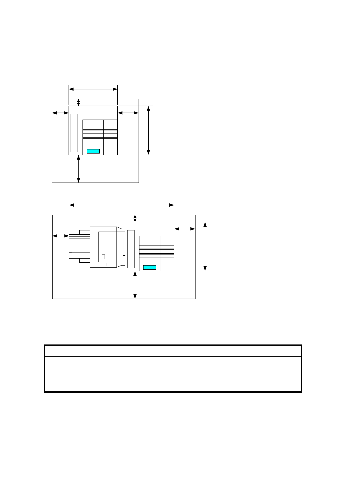
1.1.3 MACHINE SPACE REQUIREMENT
Place the machine near the power source, providing clearance as shown.
575mm (23")
B
A
G060I801.WMF
A
C
678mm (27")
A: Over 460 mm (18")
D
B: Over 100 mm (4")
C:Over 550 mm (22")
D:Over 700 mm (28")
1450mm (57")
B
C
(27")
678mm
D
G060I802.WMF
1.1.4 POWER REQUIREMENTS
!
CAUTION
1. Insert firmly the plug in the outlet.
2. Avoid using an outlet extension plug or cord.
3. Ground the machine.
1. Input voltage level: 120 V, 60 Hz: More than 10 A
220 V ~ 240 V, 50 Hz/60 Hz: More than 6 A
2. Permissible voltage fluctuation: ±10 %
3. Do not put or place anything on the power cord.
1-2

30 July, 2001 OPTIONAL UNIT COMBINATIONS
1.2 OPTIONAL UNIT COMBINATIONS
Item
No.
1 PFU (1 Tray) Items 2, 3
2 PFU (2 Trays) Items 1, 3
3 LCT Items 1, 2
4 Two-tray finisher
5 3 types of punch kit
6 Four-bin mailbox Items 4, 5
7 Duplex unit
8 3 types of memory DIMM
9HDD
10 IEEE 1394 Item 8
11 NVRAM
Options Alternative Required
Item 6
• Item 7
• I t em 8 (Total 128 MB needed) or 9
• I t em 1, 2 or 3
Item 4
NOTE: Two memory DIMMs (up to 384 MB) can be installed.
Installation
1-3
INSTALLATION FLOW CHART 30 July, 2001
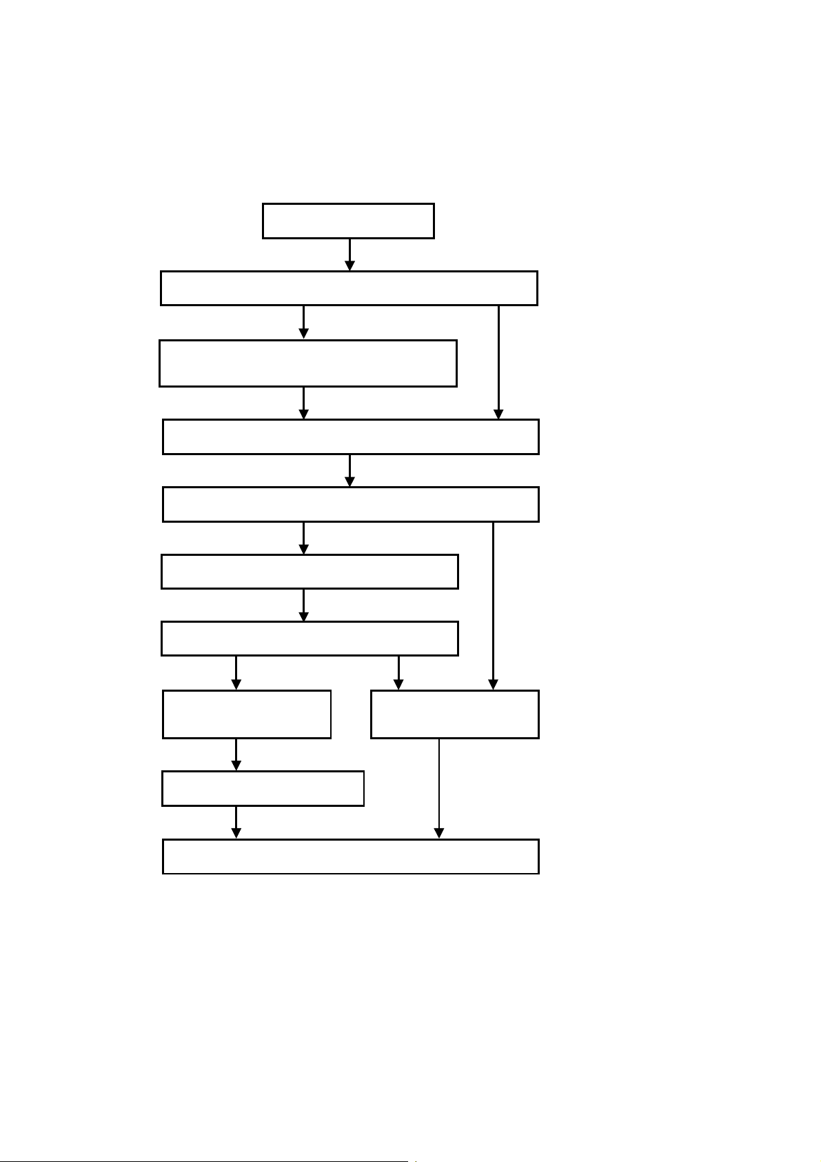
1.3 INSTALLATION FLOW CHART
The following flow chart shows how to install the optional units more efficiently.
Unpack the printer.
Will the paper feed unit or LCT be installed?
Yes No
Place the printer on the paper feed unit or LCT.
Install the paper feed unit or LCT.
Install the controller options (if required).
Will the duplex unit be installed?
Yes No
Install the duplex unit.
Will the Two-tray finisher be installed?
NoYes
Install the punch unit
(if required).
Install the two-tray finisher.
Install the printer.
Install the four-bin mailbox
(if required).
G060I002.WMF
Two-tray Finisher: Needs the duplex unit, HDD or at least 128 MB of memory,
and a paper tray unit or LCT.
Punch Unit: Needs the finisher.
IEEE1394 Board: Needs the memory DIMM.
1-4

30 July, 2001 MACHINE INSTALLATION
1.4 MACHINE INSTALLATION
Refer to the Operating Instructions for details.
If the customer has a service contract, change the settings of the following SP
modes depending on the contract type.
Item SP No. Function Default
Meter charge SP5-930-1 Specifies whether the meter charge
mode is enabled or disabled.
Meter charge mode enabl ed:
• The Counter menu appears
immediately after the Menu key is
pressed.
• The counter type selected by the
counting method (SP5-045-1) can be
displayed with the Co unt er menu.
• The counter values can also be
printed with the Counter menu.
• The selected counter starts from a
negative number.
Meter charge mode disabled:
• The Counter menu is not displayed.
• The t otal counter starts from 0.
Counting method SP5-045-1 Specifies whether the counting
method used in meter charge mode is
based on developments or prints.
Important:
This SP can only be done before t he
negative counters are reset with S P7825-001
A3/11" x 17"
double counting
PM warning
display 1
PM warning
display 2
Fax No. setting SP5-812-2 Programs the service station fax
SP5-104-1
SP5-930-3 Specifies whether the PM warning f or
SP5-930-4
to
SP5-930-5
Specifies whether the counter is
doubled for A3/11" x 17" paper.
PCUs and developm ent units is
displayed when the replace m ent t ime
arrives.
Type 1: Displayed
Type 2: Not displayed
Specifies whether the PM warning f or
the paper feed roller and transfer unit
is displayed.
number.
The number is printed on the counter
list when the meter charge mode is
selected, so that the user can fax the
counter data to the service station.
Off
Developments
No: Single
counting
Type 1
Off:
Installation
1-5

MACHINE INSTALLATION 30 July, 2001
Item SP No. Function Default
Counter reset SP7-825-1 Resets the counters to 0.
Important: This must be done at
installation after all the a bove settings
have been finished. The ne gat ive
counters used in meter charge mode
will be reset to zero.
NOTE: 1) The def ault setting for this machine is meter-charge mode off.
2) The meter-charge counter cannot be reset.
1-6
30 July, 2001 OPTIONAL UNIT INSTALLATION
1.5 OPTIONAL UNIT INSTALLATION
1.5.1 LIST OF OPTIONS
The available options are listed below. Except for the punch unit, installation is
explained in the Operating Instructions.
• Paper Feed Unit (500 sheets x 1)
• Paper Feed Unit (500 sheets x 2)
• Large Capacity Tray
• Two-tray Finisher
• Punch Unit
• Four-bin Mailbox
• DIMM Memory (64/128/256 MB)
• IEEE1394 Board
• HDD
• NVRAM
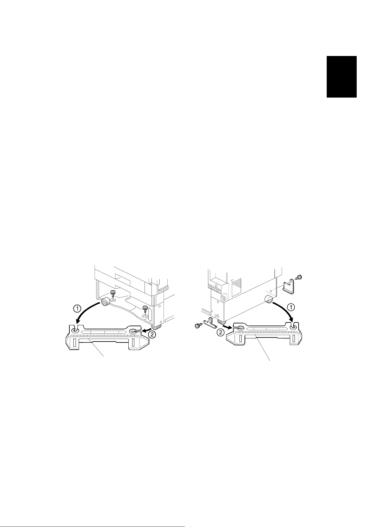
Note for Transporting the Machine
If it is difficult to slide the machine across the floor after installing the optional paper
feed unit or LCT, remove the two stands with the following procedure.
Installation
[A]
G568I901.WMF
G571R112.WMF
[B]
1. Remove all trays in the optional paper feed unit or LCT.
2. Remove the front stand [A] (! x 2).
3. Remove the rear stand [B] (! x 2, 2 brackets).
CAUTION: Reinstall the two stands in their original positions, or the machine might
tip over when drawing out the paper trays and so on.
1-7

OPTIONAL UNIT INSTALLATION 30 July, 2001
1.5.2 PUNCH UNIT INSTALLATION
Accessory Check
Check the quantity and condition of the accessories in the box against the following
list:
Description Q’ty
1. Punch unit..................................................................................1
2. Sensor arm ................................................................................1
3. Hopper.......................................................................................1
4. Step screw.................................................................................1
5. Spring.........................................................................................1
6. Spacer (2 mm)...........................................................................1
7. Spacer (1 mm)...........................................................................1
8. Tapping screw............................................................................1
9. Tapping screw............................................................................2
1-8
30 July, 2001 OPTIONAL UNIT INSTALLATION
Installation Procedure
[A]
Installation
B377I102.WMF
[C]
B377I103.WMF
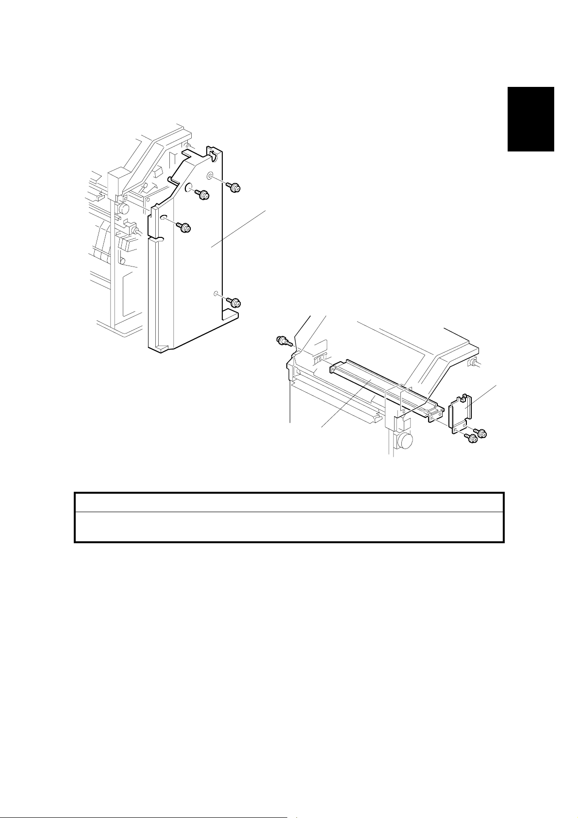
!
CAUTION
Switch off the main machine and unplug its power cord. If the two-tray
finisher is installed, disconnect it and pull it away from the machine.
1. Unpack the punch unit and remove all tapes and shipping retainers.
2. Open the front door and remove the rear cover [A] (! x 4).
3. Remove the bracket [B] (! x 2) and paper guide [C] (! x 1).
[B]
1-9
OPTIONAL UNIT INSTALLATION 30 July, 2001
[B]
[A]
[C]
B377I101.WMF
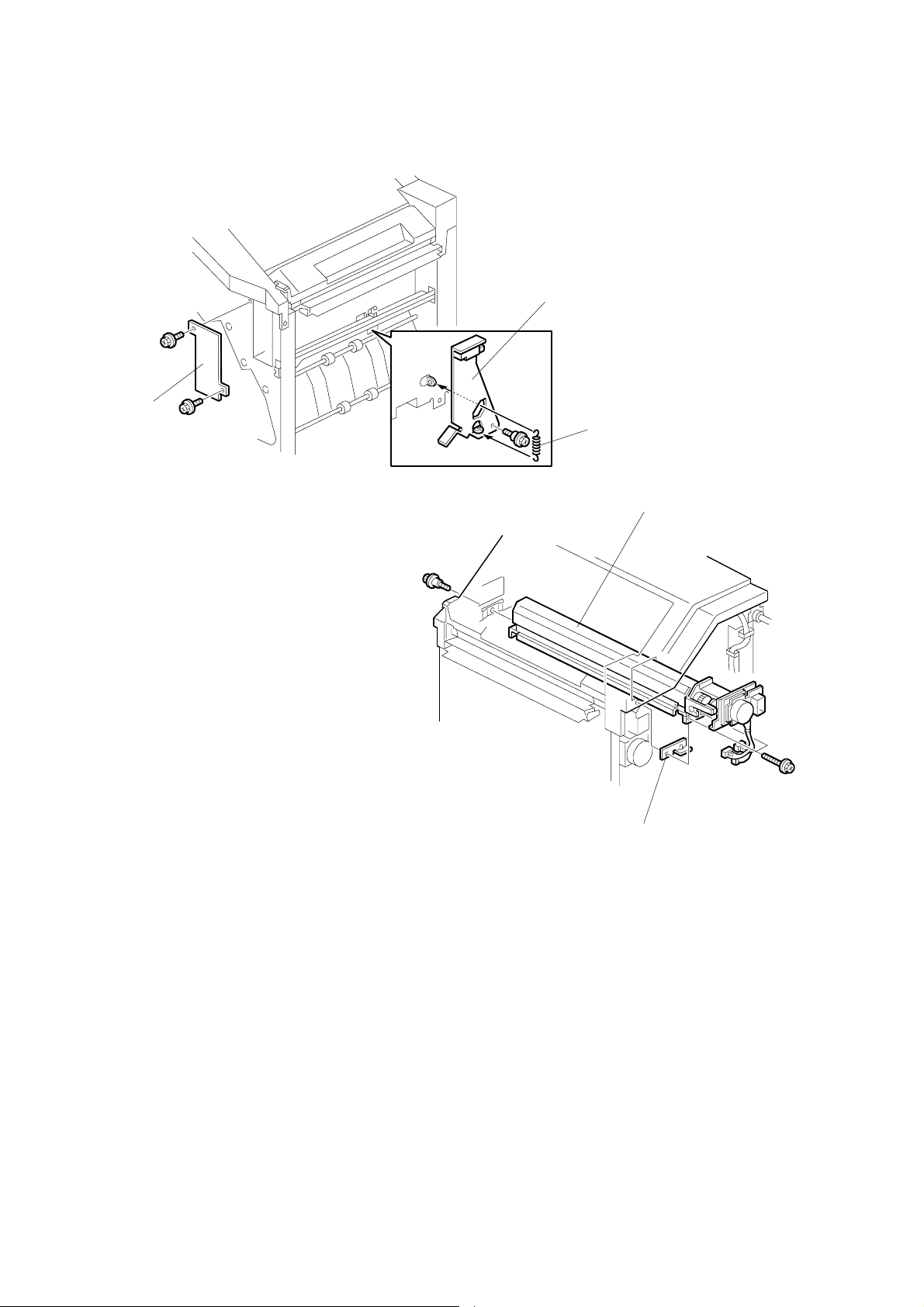
[E]
4. Remove the hopper cover [A] (! x 2).
5. Install the sensor bracket [B] (stepped ! x 1).
6. Install the spring [C].
7. Install the 2 mm spacer [D].
8. Install the punch unit [E] (! x 2, stepped ! x 1).
1-10
B377I104.WMF
[D]
30 July, 2001 OPTIONAL UNIT INSTALLATION
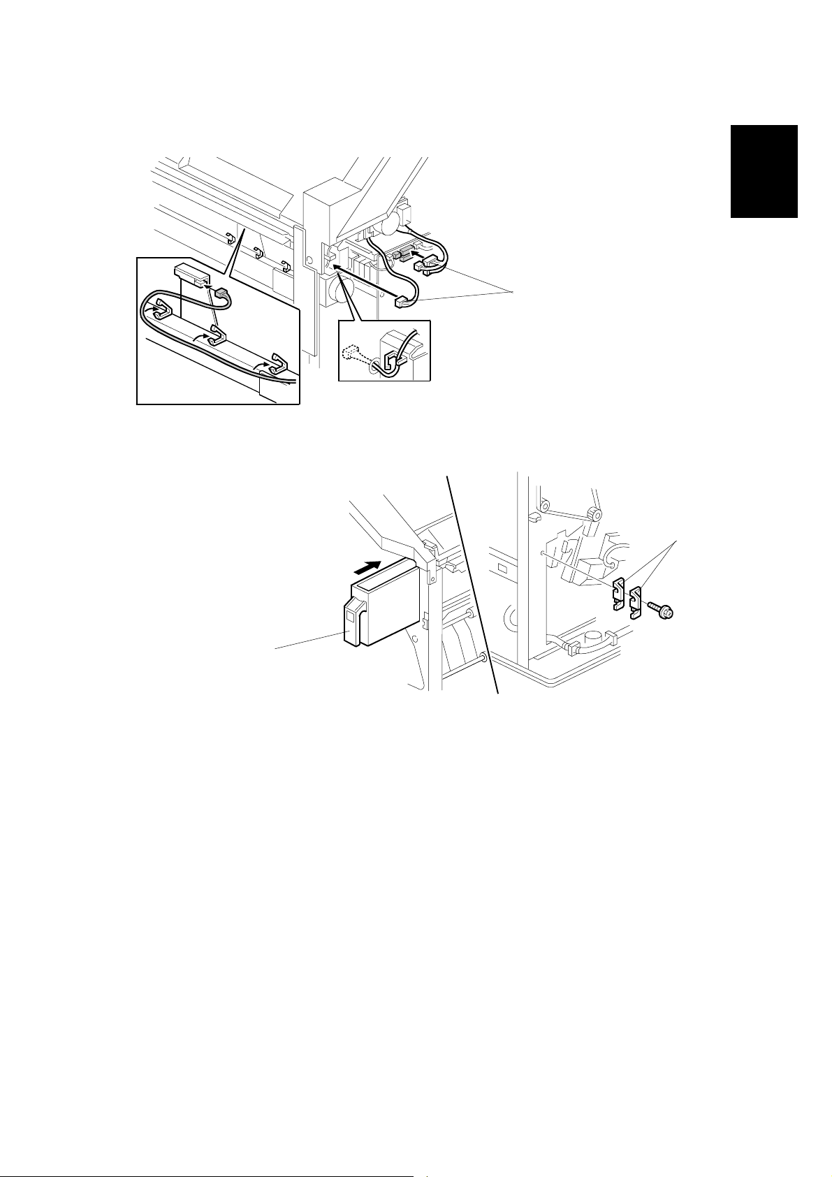
[A]
B377I200.WMF
Installation
[B]
B377I106.WMF
9. Connect the harnesses [A] and clamp them as shown.
10. Slide in the hopper [B].
11. Fasten the two 1 mm spacers [C] to the rear frame for future adjustment.
NOTE: The spacers are used to adjust the horizontal positioning of the punch
holes.
12. Reassemble the finisher an d check the punch op er ati o n.
[C]
1-11

30 July, 2001 USER MAINTENANCE
2. PREVENTIVE MAINTENANCE
2.1 USER MAINTENANCE
The following maintenance kits are avai l able for the custom er to do PM.
Type A Color (C/M/Y) PCU 100KP
Type B Color (C/M/Y) Development Unit 100KP
Type C Fusing Unit 100KP
Type D Black Development Unit / Dust Filter 100KP
Type E Waste Toner Bottle 50KP
Type F Black PCU 100KP
Type G Oil Supply Unit 20KP
Type H Paper Feed Rollers 150KP
Chart: A4(LT)/5%
Mode: 5 prints/job
Environment: Normal temperature and humidity
Yield may change depending on circumstances and print conditions.
Preventive
Maintenance
When the machine’s defau l t settings are used, an error mess age is displayed when
a maintenance counter reaches the value in the PM table below, except for the
items in maintenance kit H.
NOTE: To have the machine display the message for maintenance kit H also, set
SP5-930-4 to 1.
After the user replaces the items in a maintenance kit, the machine automatically
resets the counter for this maintenance kit, except for the items in kit H.
NOTE: Except for the items in kit H, the machine can automatically detect when
new items have been installed.
The machine stops when the counters for parts in maintenance kits C, E and G
reach the replacement value in the following table.
NOTE: To have the machine display the alert only for maintenance kits C, E, and
G, set SP5-930-3 to 0.
2-1
USER MAINTENANCE 30 July, 2001
Symbol key: C: Clean, R: Replace, L: Lubricate, I: Inspect
Main Unit
Item 20K 50K 100K 150K EM Remarks
Black PCU
Color (Y/M/C) PCU
Black Development Unit
Color (C/M/Y) Development Unit
Fusing Unit
Oil Supply Unit
Waste Toner Bottle
Dust Filter
Pick-up Roller
Feed Roller
Separation Roller
R
R
R
R
R
R
R
R
R
R
R
Included in maintenance
kit F
Included in maintenance
kit A
Included in maintenance
kit D
Included in maintenance
kit B
Included in maintenance
kit C
Included in maintenance
kit G
Included in maintenance
kit E
Included in maintenance
kit D
Included in maintenance
kit H
Included in maintenance
kit H
Included in maintenance
kit H
Punch Kit
Item 10K EM Remarks
Chads I Discard chads.
2-2
30 July, 2001 SERVICE MAINTENANCE
2.2 SERVICE MAINTENANCE
NOTE: After replacing the transfer unit, make sure to reset the maintenance
counter using SP7-804-16 and 7-804-27.
After replacing paper feed rollers, reset the maintenance counters for these
also: By-pass tray (7-804-10), Tray 1 (7-804-11), Tray 2 (7-804-12), Tray
3/LCT (7-804-13), Tray 4 (7-804-14)
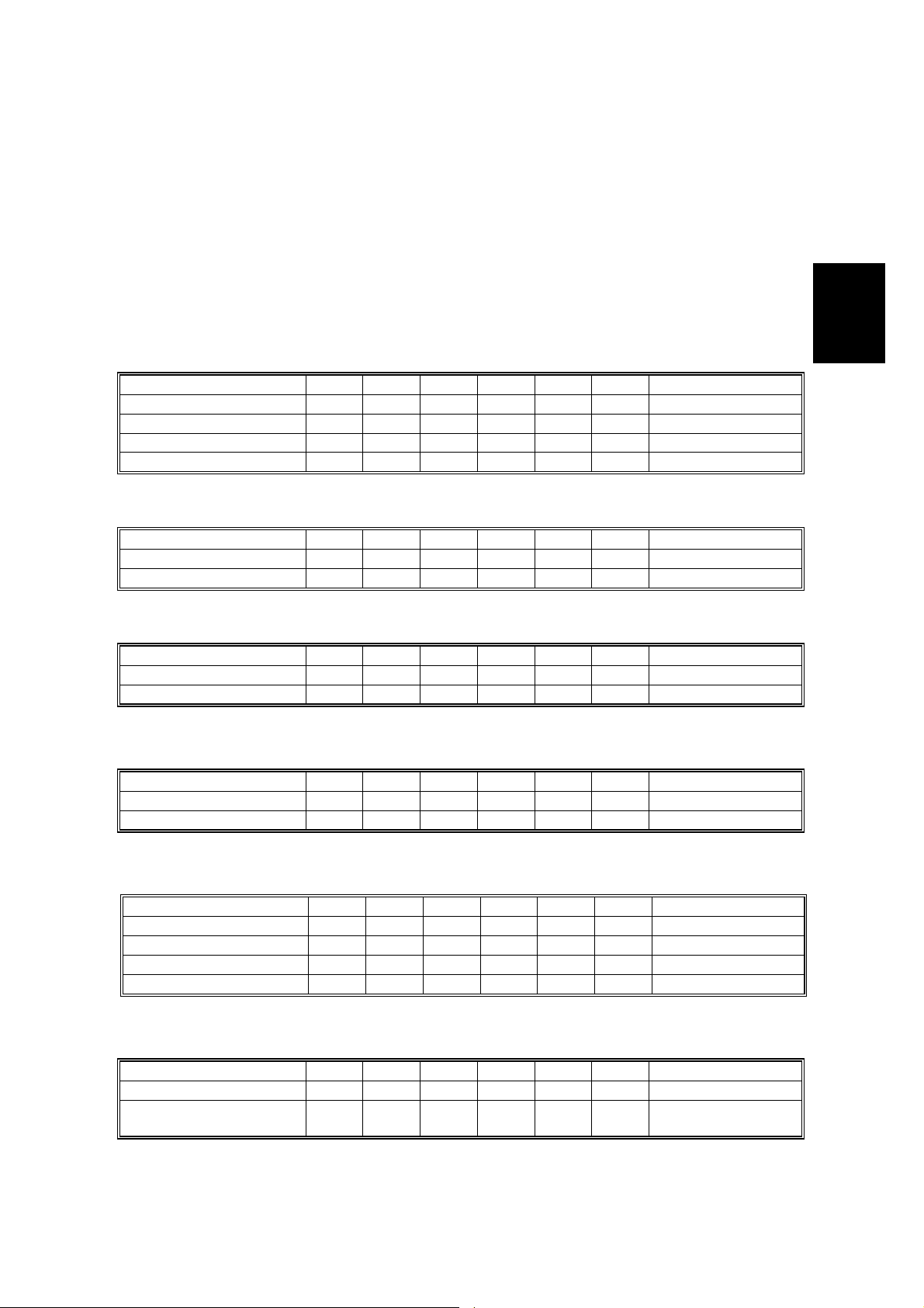
Symbol key: C: Clean, R: Replace, L: Lubricate, I: Inspect
Main unit
Item 20K 50K 100K 150K 1,000K EM Remarks
Transfer Unit R
By-pass Feed Roller R
By-pass Pick-up Roller R
By-pass Separation Roller R
One-tray Paper Feed Unit (500 sheets x 1)
Item 20K 50K 100K 150K 1,000K EM Remarks
Relay Roller C Damp cloth
Bottom Plate Pad C Damp cloth
Preventive
Maintenance
Two-tray Paper Feed Unit (500 sheets x 2)
Item 20K 50K 100K 150K 1,000K EM Remarks
Relay Roller C Damp cloth
Bottom Plate Pad C Damp cloth
LCT (2000 sheets)
Item 20K 50K 100K 150K 1,000K EM Remarks
Relay Roller C Damp cloth
Bottom Plate Pad C Damp cloth
Two-tray Finisher
Items 20K 50K 100K 150K 1,000K EM Remarks
Rollers C Damp cloth
Discharge Brush C Dry cloth
Sensors C Blower brush
Jogger Fences I Replace if required.
Four-bin Mailbox
Item 20K 50K 100K 150K 1,000K EM Remarks
Rollers C Damp cloth
Tray Paper Sensors
Blower blush or dry
C
cloth
2-3

30 July, 2001 SPECIAL TOOLS
3. REPLACEMENT AND ADJUSTMENT
!
CAUTION
Turn off the main switch and unplug the machine before beginning any of
the procedures in this section.
NOTE: This manual uses the following symbols.
☛ : See or refer to ! : Screw " : Connector
# : Clip ring $ : E ring
3.1 SPECIAL TOOLS
Part Number Part Name Q’ty
A2309352 Flash Memory Card - 4MB 1
G0219350 Loop-back connector - Parall el 1
C4019503 20X Magnification Scope 1
Adjustment
Replacement
3-1
 Loading...