

MB 716 Service manual

Service manual & parts
catalog
7
Colour Printer MB 716

MB CONFIDENTIAL
PREFACE
This manual describes the procedures of the maintenance of the MB 716 of printer.
The document is produced for maintenance personnel use. For details on the procedures for handling the
MB 716 of printer, see its user documentation.
Note!
• The descriptions in this manual are subject to change without prior notice.
• In preparing the document, efforts have been made to ensure that the information in it is accurate.
However, errors may be crept into the document. MB assumes no responsibility for any
damage resulting from, or claimed to be the results of, those repairs, adjustments or modifications to the printers which are made by users using the manual.
• The parts used for the printers are sensitive and, if handled improperly, may be damaged. It is
strongly recommended that the products are maintained by maintenance men registered with
MB.
41955801TH Rev.1 3 /

MB CONFIDENTIAL
CONTENTS
1. CONFIGURATIONS ......................................................................................... 7
1.1 System Configuration....................................................................................................... 7
1.2 Printer Configuration ........................................................................................................8
1.3 Option Configuration ........................................................................................................ 9
1.4 Specifications................................................................................................................. 10
2. OPERATION DESCRIPTION ......................................................................... 12
2.1 Main Board (TIG PWB) .................................................................................................. 14
2.2 Engine Controller Board (K7N PWB) ............................................................................. 16
2.3 Power Units.................................................................................................................... 17
2.4 Mechanical Processes .................................................................................................. 18
2.4.1 Electrophotographic process............................................................................ 19
2.4.2 Paper running process ..................................................................................... 24
2.5 Sensor............................................................................................................................ 32
2.5.1 Paper related sensors ...................................................................................... 32
2.5.2 Other sensors................................................................................................... 33
2.6 Color Misalignment Correction....................................................................................... 34
2.7 Transfer Control Responds to Environmental Changes
(Room Temperatures and Relative Humidities)............................................................. 34
2.8 Paper Jam Detection ..................................................................................................... 35
2.9 Cover-Open ...................................................................................................................36
2.10 Toner Low Detection...................................................................................................... 37
2.11 Page Size Detection ...................................................................................................... 38
2.12 Operation at Power-on................................................................................................... 39
2.12.1 Self-diagnostic test........................................................................................... 39
2.13 Color Misalignment Detection ........................................................................................ 40
2.14 Version Read of Units Replaced Periodically ................................................................ 41
2.15 Life Count for Units Replaced Periodically..................................................................... 41
2.16 Toner Consumption Detection ...................................................................................... 41
3. PARTS REPLACEMENT................................................................................ 42
3.1 Precautions in Replacing Parts...................................................................................... 42
3.2 Parts layout .................................................................................................................... 44
3.3 Replacing Parts..............................................................................................................50
3.3.1 Top Cover......................................................................................................... 52
3.3.2 LED Head/ LED Assy Spring............................................................................ 53
3.3.3 Top Cover Unit ................................................................................................. 54
3.3.4 Control Panel Assy/ Control Panel Bezel/ LED Control PWB/
Toner Sensors Stacker Full Sensor/ Control Panel/
Control Panel Tape Harness/ Eject Rollers..................................................... 55
3.3.5 Top Cover Handle/ Top Cover Latch/ Top Cover Latch Spring........................ 56
3.3.6 Eject Guide Assy .............................................................................................. 57
3.3.7 Cassette Assy/ Front Cover Assy/ Front Cover Inner Baffle ........................... 58
3.3.8 Retard Pad Assy/ Retard Pad Assy Spring ...................................................... 59
3.3.9 Feed Roller and Nudger Roller......................................................................... 60
3.3.10 Rear Cover....................................................................................................... 61
3.3.11 Face-Up Tray.................................................................................................... 62
3.3.12 Left Side Cover................................................................................................. 63
3.3.13 Right Side Cover .............................................................................................. 64
3.3.14 Multipurpose Tray Assy/ Multipurpose Tray Cover Assy/ Links/
Multipurpose Tray Top Cover/ Multipurpose Tray Drive Gear.......................... 65
3.3.15 Drum Contact Assys......................................................................................... 66
3.3.16 Media Thickness Sensor Assy......................................................................... 67
3.3.17 Registration Roller Assy (A)/ Registration Drive Gear (A)................................ 68
3.3.18 Registration Roller Assy (B) ............................................................................. 69
3.3.19 Registration Clutch and Registration Motor Assy............................................. 70
41955801TH Rev.1 4 /

MB CONFIDENTIAL
3.3.20 Main Cooling Fan ............................................................................................. 71
3.3.21 Color Registration Sensor Assy........................................................................ 72
3.3.22 Duplex Guide Assy........................................................................................... 73
3.3.23 Electrical Chassis Cooling Fan......................................................................... 74
3.3.24 Printer Engine Controller PWB......................................................................... 75
3.3.25 Printer Unit Chassis.......................................................................................... 76
3.3.26 Entrance Cassette Sensor Actuator................................................................. 77
3.3.27 Entrance Sensor PWB...................................................................................... 78
3.3.28 Entrance MT Sensor Actuator / Entrance Belt Sensor Actuator /
Entrance Waste Chassis Sensor Actuator ...................................................... 79
3.3.29 Fuser Exit Roller............................................................................................... 80
3.3.30 Exit Sensor Assy .............................................................................................. 81
3.3.31 Fuser Latching Handle (L)................................................................................ 82
3.3.32 Belt Motor Assy ................................................................................................ 83
3.3.33 Fuser Latching Handle (R) ............................................................................... 84
3.3.34 Main Motor Assy............................................................................................... 85
3.3.35 Main Feeder Drive Motor.................................................................................. 86
3.3.36 Contact Assy/ Left Plate Assy .......................................................................... 87
3.3.37 Low Voltage Power Supply............................................................................... 88
3.3.38 High voltage power supply ............................................................................... 89
3.3.39 Main Feed Assy................................................................................................ 90
3.3.40 Cassette/ Left Guide Assy................................................................................ 91
3.3.41 Cassette/ Right Guide Assy.............................................................................. 92
3.3.42 Fuser Unit......................................................................................................... 93
3.3.43 Belt Unit............................................................................................................ 94
3.3.44 Duplex Unit....................................................................................................... 95
3.3.45 Guide Rails (L) and (R)..................................................................................... 96
3.3.46 Duplex Transport Assembly ............................................................................. 97
3.3.47 CU Assy............................................................................................................ 99
4. Adjustment .................................................................................................. 101
4.0 System Maintenance MENU........................................................................................ 101
4.0.1 ID Check Pattern Printing ( " TEST PRINT MENU " item )............................. 102
4.1 Maintenance Mode and Functions............................................................................... 102
4.1.1 Maintenance menu......................................................................................... 102
4.1.2 Engine maintenance mode............................................................................. 104
4.1.2.1 Operator panel ................................................................................ 104
4.1.2.2 Normal self-diagnostic mode (Level 1)............................................ 104
4.1.2.2.1 Entering self-diagnostic mode (Level 1).......................... 105
4.1.2.2.2 Exiting the self-diagnostic mode ..................................... 105
4.1.2.3 Switch scan test .............................................................................. 105
4.1.2.4 Motor clutch test.............................................................................. 109
4.1.2.5 Test print ......................................................................................... 111
4.1.2.6 Initializing NVM ............................................................................... 115
4.1.2.7 Displaying the consumables counter .............................................. 116
4.1.2.8 Displaying the consumables continuation counter .......................... 116
4.1.2.9 Panel display details ....................................................................... 117
4.1.3 Various print jobs with single printer unit attached with a controller............... 122
4.2 Adjustment After Replacing Parts ................................................................................ 123
4.2.1 Precautions in replacing the engine control board ......................................... 123
4.2.2 Precautions in replacing EEPROM................................................................. 123
4.2.3 Replacing EEPROM after replacing the TIG board........................................ 124
4.2.4 Destination Setting (Checking Metod: Printing Demo Page).......................... 124
4.2.5 Recovery Flash ROM data on TIG board....................................................... 125
4.3 Adjusting the Density ................................................................................................... 125
4.4 Paper Thickness Detection Sensitivity Adjustment and Media Thickness Detection
Value Check................................................................................................................. 126
41955801TH Rev.1 5 /

MB CONFIDENTIAL
5. regular maintenance ................................................................................... 128
5.1 Parts Replaced Regularly ............................................................................................ 128
5.2 Cleaning....................................................................................................................... 128
5.3 Cleaning the LED Lens Array ...................................................................................... 128
5.4 Cleaning the Pick-up Roller ......................................................................................... 128
6. Troubleshooting Procedures ..................................................................... 129
6.1 Precautions before troubleshooting ............................................................................. 129
6.2 Precautions before handling an abnormal image ........................................................ 129
6.3 Precautions upon handling an abnormal image........................................................... 129
6.4 Preparing for Troubleshooting ..................................................................................... 130
6.5 Troubleshooting Procedure.......................................................................................... 130
6.5.1 LCD message list ........................................................................................... 131
6.5.2 Preparing for troubleshooting ......................................................................... 137
6.5.3 Troubleshooting for abnormal images............................................................ 148
6.6 Fuse check................................................................................................................... 163
7. CONNECTION DIAGRAM............................................................................164
7.1 Resistance Checks ...................................................................................................... 164
7.2 Program/Font ROM Layouts ........................................................................................ 168
8. Parts List......................................................................................................174
APPENDIX A INTERFACE SPECIFICATIONS ................................................. 190
APPENDIX B 2ND/3RD TRAY MAINTENANCE .............................................. 194
APPENDIX C MB 716 ERROR MESSAGES .................................................... 199
1. MB 716 (Error messages) ........................................................................................... 199
2. MB 716 (Error messages : Related to Color, Media Detect) ....................................... 206
3. MB 716 (Warning messages : Related to usage, media) ............................................ 209
4. MB 716 (Warning messages : Job Account) ............................................................... 210
5. MB 716 (Other Warning) ............................................................................................. 211
41955801TH Rev.1 6 /
M
M
M
M
M
M
M
M
LED Head
Centronics I/F
USB I/F
2 × Option Slots
Junction Board
Pulse Motor
Engine Control
Low Voltage
Power Unit
Fuser
Unit
High Voltage
Power Unit
2nd/3rd Tray
Duplex
Unit
Belt
Unit
<Sensors, Switches and Thermistors>
Paper size sensor (4 bits)
Paper empty sensor
Paper near empty sensor
MT paper empty sensor
FF home switch
Loading sensor 1
Loading sensor 2
C-ID
Unit
M-ID
Unit
Y-ID
Unit
K-ID
Unit
C ID M ID Y ID K IDBelt Heat
MT/
Registration
Hopping
Operator Panel
3 × ROM
DIMMs
4 × RAM
DIMM
IDE
I/F(HDD)
DC Fan
Note
Note Option Slot:
LAN Card made by JCI
< advanced Sensors,>
Media Thickness Detection
Density Detection
Color Misalignment Detectin
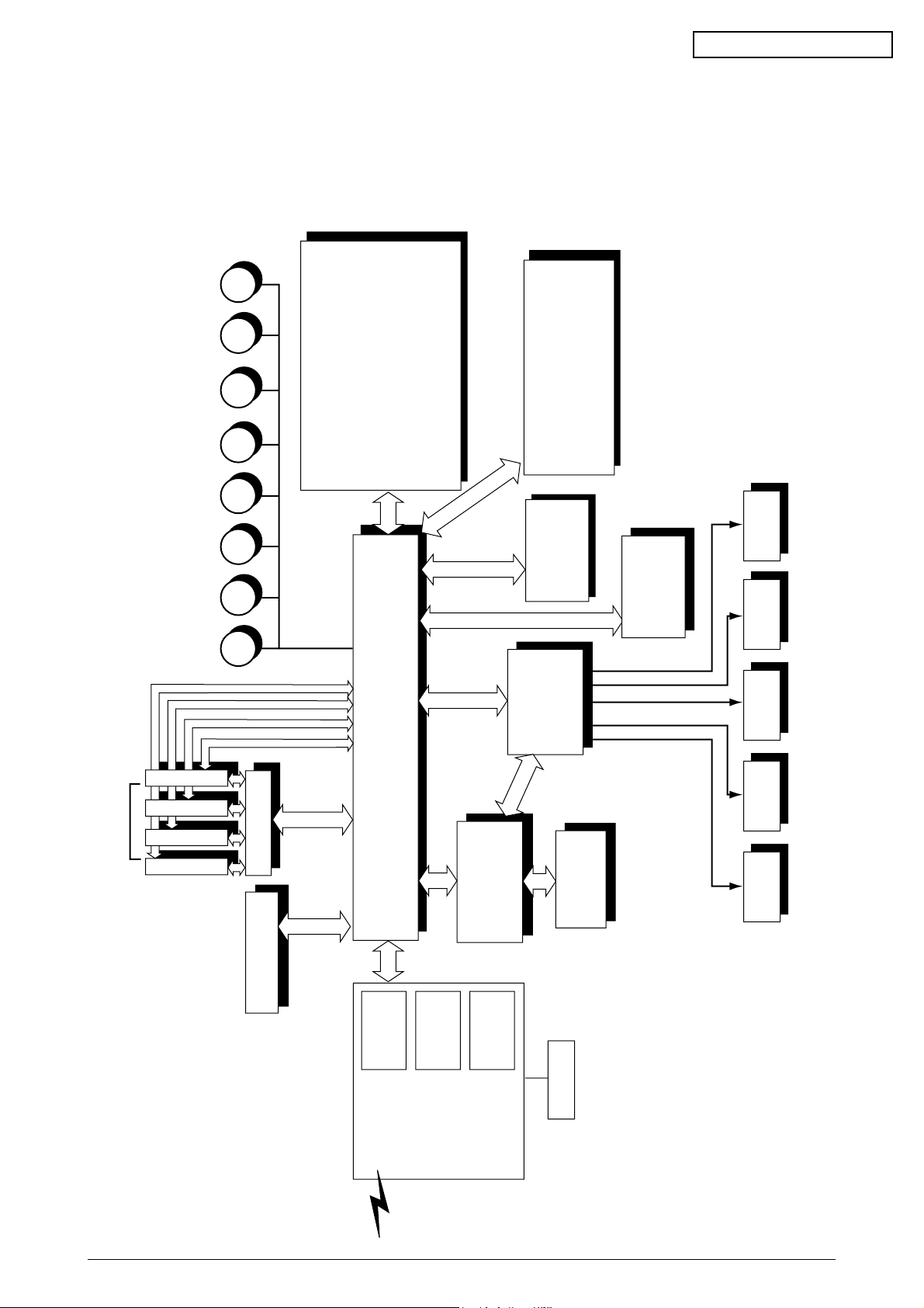
1. CONFIGURATIONS
1.1 System Configuration
Figure 1-1 shows the system configuration of the MB 716 of printer.
MB CONFIDENTIAL
Figure 1-1
41955801TH Rev.1 7 /
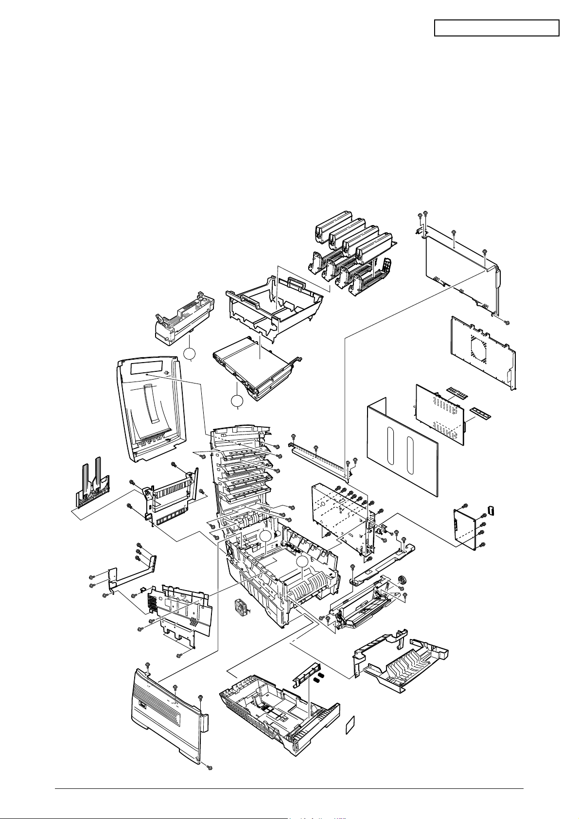
1.2 Printer Configuration
The inside of the printers is composed of the followings:
• Electrophotographic Processor
• Paper Paths
• Controller Block (CU and PU)
• Operator Panel
• Power Units (High Voltage Unit and Low Voltage Unit)
Figure 1-2 shows the printer configuration.
MB CONFIDENTIAL
B
A
A
B
B
A
A
Figure 1-2
41955801TH Rev.1 8 /
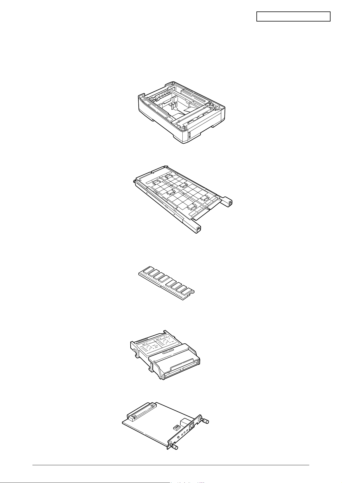
1.3 Option Configuration
The followings are available as options on the C7000 Series of printers.
(1) 2nd Tray/ 3rd Tray
(2) Duplex Unit
MB CONFIDENTIAL
Note: Don’t use one for
C9200/C9400
(3) Expansion Memory 64/128/256/512 MB
(4) Internal Hard Disk
Note: Don’t use one for
C9200/C9400
Note: Don’t use one for
C9200/C9400
Note: Don’t use one for
C9200/C9400
(5) Ethernet Board
Note: Don’t use one for
C9200/C9400
41955801TH Rev.1 9 /

1.4 Specifications
(1) External Dimensions Height: 430mm Width: 430mm Length: 620mm
(2) Weight 42 kg
(3) Papers Type: Ordinary paper, Transparencies (Recommended: MLOHP01)
(4) Print Speed Color: 20 pages per minute (Transparency: 8 pages per minute)
(5) Resolution 600 × 1200 dots per inch
MB CONFIDENTIAL
Size: Postal card, Legal 13" or 14", Executive, A4, A5, B5, A6 (Only
the 1st tray and the front feeder support A6 and postal-card
sizes.)
Weight: 1st tray55 kg to 151 kg (64 to 176g/m2)
Front feeder 55 kg to 172 kg (64 to 203g/ m2)
Monochrome: 24 pages per minute (Transparency: 12 pages per minute)
Postal Card, Label, Thick Paper: 12 pages per minute
(6) Power Input 115 - 127 V , 220 - 240 V
(7) Power Consumption Peak: 1500W Normal Operation: 500W (5% duty)
Idle: 150W Power Saving Mode: 45W or less
(8) Frequency 50Hz or 60Hz ±2Hz
(9) Noise Operation: 56 dB (Without second tray)
Standby: 45 dB
Power Saving: 43 dB
(10) Consumable Life Toner Cartridge: 5,000 pages (5% duty) (each of Y, M, C and K)
Large-Capacity Toner Cartridge: 10,000 pages (5% duty)
(each of Y, M, C and K)
Image Drum: 30,000 pages (5% duty, Continuous printing)
(each of Y, M, C and K)
(11) Parts Replaced Periodically Fuser Unit Assy: Every 60,000 pages
Belt Cassette Assy: Equivalent of 60,000 pages (3 pages/job)
41955801TH Rev.1 10 /

MB CONFIDENTIAL
(12) Temperatures and Relative Humidities
Temperature
Temperature Condition
Temperature (˚F)Temperature (˚C) Remark
Operation 50 to 89.6 10 to 32 17 to 27˚C
(Temperatures to assure full
color print quality)
Non-Operation 32 to 109.4 0 to 43 Power-off
Storage (Max. One Year) -14 to 109.4 -10 to 43 With drum and toner
Transport (Max. One Month) -20 to 122 -29 to 50 With drum and without toner
Transport (Max. One Month) -20 to 122 -29 to 50 With drum and toner
Humidity
Humidity Condition
Relative Humidity Max. Wet-Bulb Remark
(%) Temperature(˚C)
Operation 20 to 80 25 50 to 70% (Humidities to assure full
color print quality)
Non-Operation 10 to 90 26.8 Power-off
Storage 10 to 90 35
Transport 10 to 90 40
(13) Printer Life 600,000 pages (on a A4-size basis) or five years
41955801TH Rev.1 11 /
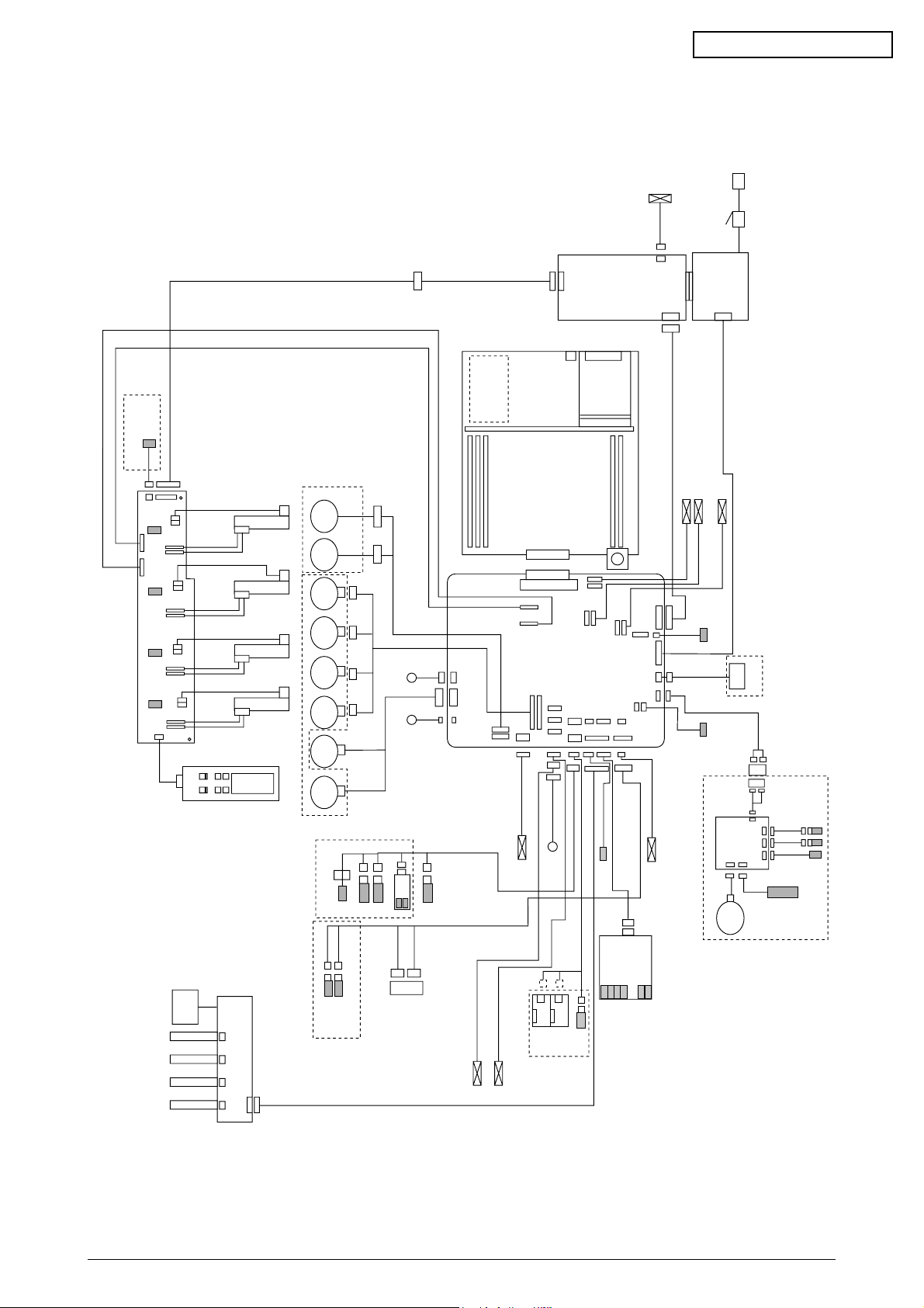
2. OPERATION DESCRIPTION
N71 Board
Belt
Fuse
K Fuse
Y Fuse
M Fuse
C Fuse
JODEN
14P
Paper Tray 1 Paper Empty
Paper Tray 2 Near Empty
3P
3P
WHITE
BLUE
OPTION
7P
7P
BLUE
BLUE
BLUE
WHITE
WHITE
KPOW
K1200
YPOW
Y1200
CPOW
C1200
OPTN
MPOW
M1200
YELLOW
FAN1 (Pr)
FAN2 (Pow)
Plate Senosr
Density
5P
red
Gray
Blue
Z7L
Z7R
9P
22P
14P
14P
3P3P
3P
2P
9P
10P
16P
16P
4P
R71 board
HOP(INSNS1)
PAPIN(INSNS2)
PSWR(WRSNS)
TNRFUL
Manual Bypass Feeder (MBF)
Hopping
Motor
FF/Regist
Motor
K IDU
Motor
Y IDU
Motor
M IDU
Motor
C IDU
Motor
Belt
Motor
Heat
Motor
MBF Stage
MBF Paper Empty
Duplex Unit
DUP
V71 Board
Motor
Clutch
INSENS
FSENS
RSENS
Main
14P
7P
7P
7P
7P
Front Cover
Open
Microswitch
Upper Cover
Open Microswitch
COVOPN
TR10P
JODEN
REG
FAN8
8P
BEL THET
FEED
FSENS
RSNS
RCL
FAN1
FAN2
PCB-K7N
POWER
FAN
FAN(LEFT)
HVOLT
PSIZE
FCOVER
DUPLEX
CUIF
FAN4
black
yellow
yellow
yellow
red
red
red
red
red
red
FAN7
blue
blue
FAN5
PARTTEMP
yellow
yellow
3P
2P
Exit sensor
cable40
Regist
clutch
SHUTTER
ID
DCL
HOPFF
Main Motor Assy Belt Motor Assy
46
WHITE YELLOW
K LED HEAD
Control Panel
X7N board
Y LED HEAD
M LED HEAD
C LED HEAD
Toner Sensor (Y73-board)
Paper Size
Sensor
PXC-Board
AC Switch
AC
CN1 CN1
CN5
CN2
High -voltage
power supply
Low-voltage
power supply
CN3
CN2
10P
26P
26P
16P
3P
6P
16P
3P
16P
8P
2P
Exit solenoid
Cord 7
6P
TNRK
PANEL
STUCK
POWER
4P 4P
4P 4P 4P 4P
RED WHITE
BLACK YELLOW RED BLUE
6P
KPOW2
TNRY
YPOW2
TNRM
MPOW2
TNRC
CPOW2
OPTN
16P
3P
3P
3P3P3P
14P
STUCKFULL
Sns.
3P
FAN0
Up/Down
OHP Sen.
4P
4P
green
HUM
TEMP
yellow
yellow
yellow
Paper
thickness
2
RAM
TIG board
ROM
HDD
LAN
USB
CENTRO
FAN
FAN
10
2P
shutter clutch
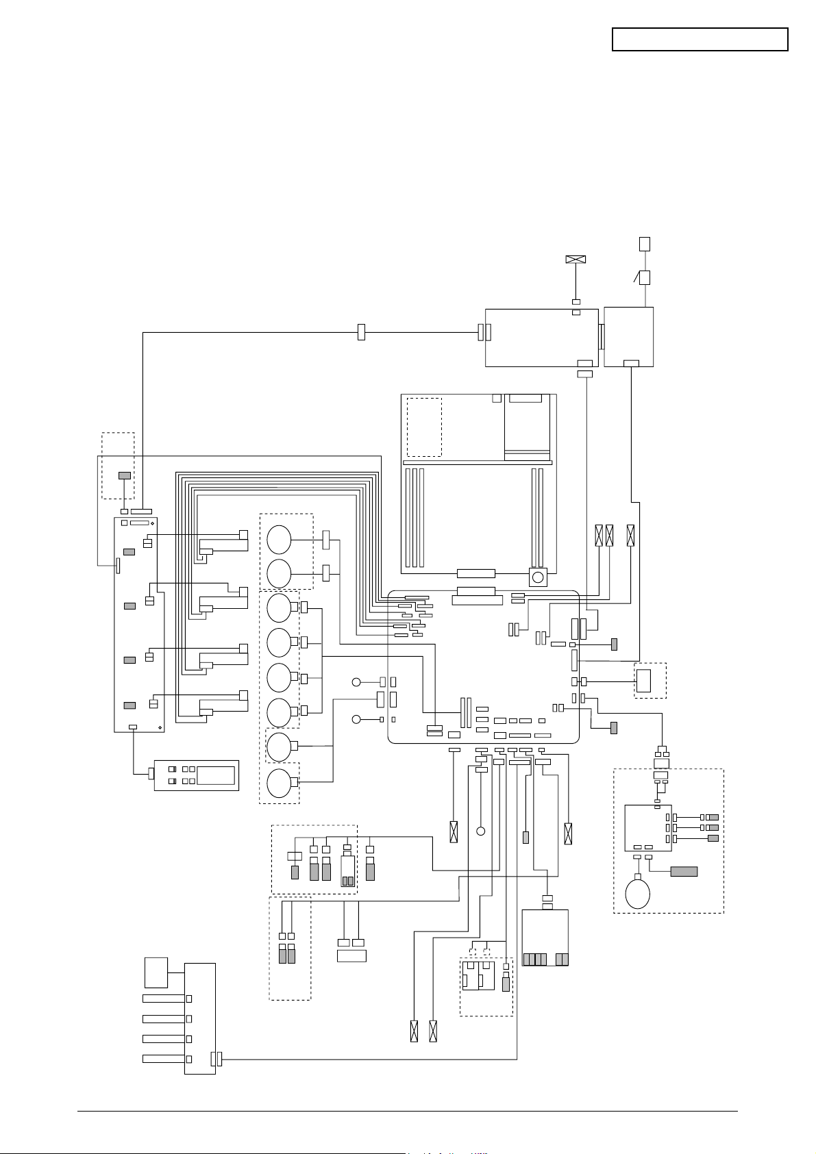
The MB 716 of printer, tandem color electrophotographic page printers, adopt technologies
such as an LED array, OPC, dry single-component non-magnetic developing, roller transfer and
heat-compression fusing. A black-writing printing method by shedding light on print areas is used.
Figure 2-1-1(600dpi),2-1-2(1200dpi) provides the block diagram of the printers.
MB CONFIDENTIAL
41955801TH Rev.1 12 /
Figure 2-1-1 600dpi
N71 Board
Belt
Fuse
K Fuse
Y Fuse
M Fuse
C Fuse
JODEN
14P
Paper Tray 1 Paper Empty
Paper Tray 2 Near Empty
3P
3P
WHITE
BLUE
OPTION
7P
7P
BLUE
BLUE
BLUE
WHITE
WHITE
YELLOW
FAN1 (Pr)
FAN2 (Pow)
Plate Senosr
Density
5P
red
Gray
Blue
Z7L
Z7R
9P
22P
14P
14P
3P3P
3P
2P
9P
10P
16P
16P
4P
R71 board
HOP(INSNS1)
PAPIN(INSNS2)
PSWR(WRSNS)
TNRFUL
Manual Bypass Feeder (MBF)
Hopping
Motor
FF/Regist
Motor
K IDU
Motor
Y IDU
Motor
M IDU
Motor
C IDU
Motor
Belt
Motor
Heat
Motor
MBF Stage
MBF Paper Empty
Duplex Unit
DUP
V71 Board
Motor
Clutch
INSENS
FSENS
RSENS
Main
14P
7P
7P
7P
7P
Front Cover
Open
Microswitch
Upper Cover
Open Microswitch
COVOPN
TR10P
JODEN
REG
FAN8
8P
BEL THET
FEED
FSENS
RSNS
RCL
FAN1
FAN2
PCB-K7N
POWER
FAN
FAN(LEFT)
HVOLT
PSIZE
FCOVER
DUPLEX
CUIF
FAN4
black
yellow
yellow
yellow
red
red
red
red
red
red
FAN7
blue
blue
FAN5
PARTTEMP
yellow
yellow
3P
2P
Exit sensor
cable40
Regist
clutch
SHUTTER
ID
DCL
HOPFF
Main Motor Assy Belt Motor Assy
46
WHITE YELLOW
K LED HEAD
Control Panel
X7N board
Y LED HEAD
M LED HEAD
C LED HEAD
Toner Sensor (Y7X-board)
Paper Size
Sensor
PXC-Board
AC Switch
AC
CN1 CN1
CN5
CN2
High -voltage
power supply
Low-voltage
power supply
CN3
CN2
10P
26P
26P
16P
3P
6P
16P
3P
16P
8P
2P
Exit solenoid
Cord 7
6P
TNRK
PANEL
STUCK
POWER
4P 4P
4P 4P 4P 4P
RED WHITE
BLACK YELLOW RED BLUE
6P
KPOW2
TNRY
YPOW2
TNRM
MPOW2
TNRC
CPOW2
HEAD
32
32P
3P
3P
3P3P
3P
14P
STUCKFULL
Sns.
3P
FAN0
Up/Down
OHP Sen.
4P
4P
green
HUM
TEMP
yellow
yellow
yellow
Paper
thickness
2
RAM
TIG board
ROM
HDD
LAN
USB
CENTRO
FAN
FAN
10
2P
shutter clutch
34P
32P
HEAD
34
CPOW
C1200
M1200
MPOW
YPOW
Y1200
K1200
KPOW
12P
12P
12P
12P
14P
14P
14P
14P
34P
HEAD32
HEAD34
MB CONFIDENTIAL
41955801TH Rev.1 13 /
Figure 2-1-2 1200dpi
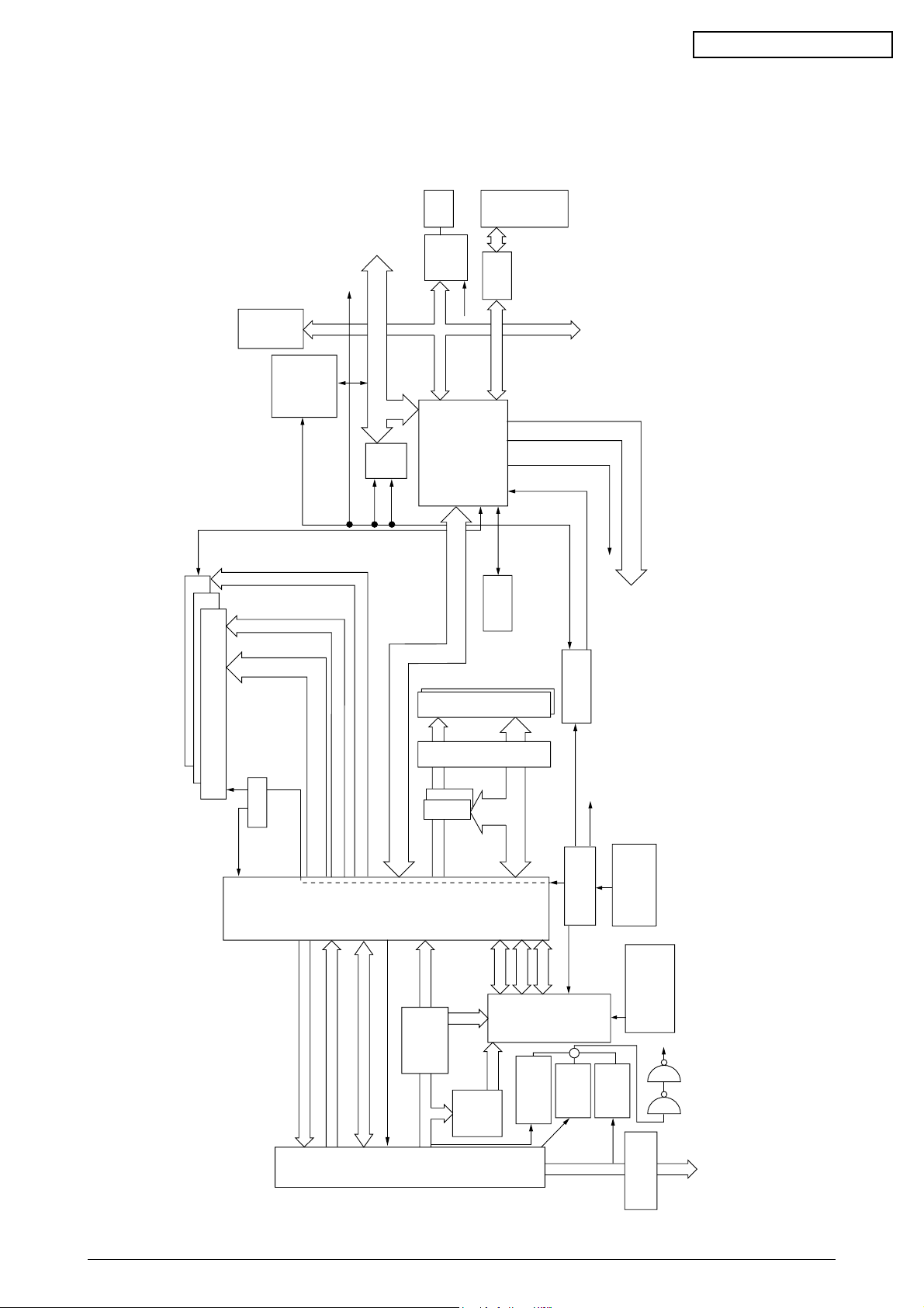
2.1 Main Board (TIG PWB)
3
PU-CU
200
pin
C2516
EEPROM
Video Data K, Y, M, C
Video I/F From PU
PU-CU I/F To C2 LSI
to PU PU-CU Command I/F
to PU Panel I/F
A [31:0]
SUB Bus A/D [31:0], Cont
[15:0]
SPD
[2]
[1]
[0]
SUB Bus
a Line Address. Cont
b Line Address. Cont
D [63:0]
[15:0][7:0]
D [63:0]
D [63:0] D [63:0]
D
[15:0]
Cont
Panel I/F From C2 LSI
3.3V
Reset IC
2.5V
1.8V
12V
3.3V
5V
2.5V
14.31818MHz
Crystal
Resonator
M62733ML
(PU3V)
PST596
(PU12V)
PST596
(+5V)
internal
CPU CLK
setting Resister
PLL702-01
3.3V
Regulator
PPC
750cx
Core:1.8V
I/O:2.5V
2.5V
Regulator
CA1 LSI
MHM
2030-003
(uPD856
11N7)
Core:2.5V
I/O:3.3V
CPU I/O:2.5V
C2 LSI
MHM2031-002
DRCLK
3.3V
100MHz
RAMCLK
From 702
LVC
161284
PLL102-5
33MHz
×
5
33MHz 3.3V
×
4
33MHz 3.3V
USB
C
e
n
t
r
o
L60851
PCI
Slot
FPGA
for IDE
CENT
PCI
Reset
IDE
HDD
I/O 2.5V
74LVC04
to each LSI
MPUCLK
2.5V
100MHz
CA1CLK
2.5V
100MHz
48MHz
to USB
33MHz
33MHz
33MHz
Local
33MHz
48MHz
A,Cont
1.8V
Regulator
+
Flash
Mask 32bit
×
2
ROM DIMM
×
2
SDRAM DIMM
×
3
SDRAMCLK
×
12
3.3V 100MHz
1
2
PCI BUS [31:0]
Figure 2-2 provides the block diagram of the main control board (TIG PWB).
MB CONFIDENTIAL
41955801TH Rev.1 14 /
Figure 2-2

MB CONFIDENTIAL
(1) CPU
The CPU is PowerPC750CXe, a 64-bit bus RISC processor, which inputs an 100-MHz CLK
(= BUS CLK), and operates at 450MHz that is 4.5 times the input.
(2) Cache
PPC750Cxe has its cache only inside of it.
Speed: Same as CPU Core CLK speed
Capacity:
Primary Cache: 32 K bytes in D-cache capacity, 32 K bytes in I-cache capacity
Secondary Cache: 256 K bytes
(3) ROM
ROM is to be inserted into the two 168 pin DIMM slots. The slot A is for program ROM and
the slot B is for Japanese kanji fonts. The slot C is not assigned.
(4) RAM
RAM is to be inserted into the three 168 pin DIMM slots. The DIMMs must be fitted in
descending labeled type No. order into the slots 1, 3, 2 and 4.
SDRAM DIMM Specifications:
Speed: PC133 or more
Capacity: 64/128/256/512 MB
Configuration: Without parity. Without ECC. SPD information is required.
(5) EEPROM
EEPROM, an 8-pin DIP package, is to be inserted into the IC socket. The EEPROM is of 16
Kbits for 3.3V power supply, and settings for controlling the controller block are stored in it.
(6) Flash ROM
A 4Mbyte flash ROM is surface-mounted on the TIG board. The flash ROM is composed of
four 2048k-by-16bit chips, and fonts and macros can be stored in it.
(7) Memory Control LSI (CAI)
A 696-pin BGA package ASIC made by NEC. The chip mainly controls a CPU I/F, memory,
video data compression and decompression, and a PU-video I/F.
(8) Interface Control LSI (C2)
A BGA package ASIC made by Toshiba, which controls a PU command I/F, operator panel
I/F, IDE I/F, Centronics I/F, USB I/F, PCI I/F, EEPROM and a SPD (SDRAM DIMM) I/F.
(9) IDE HDD
An IDE connector is surface-mounted on the board to which an IDE HDD assembled using
exclusive molds will be connected. The IDE HDD is used for storing font data, spooling edited
video data and registering form data.
(10) PCI Bus Option
Two PCI I/F slots are provided for option board use. The bus, which uses an MB original
connector, can accept an Ethernet board.
(11) Host Interface
Standard: Centronics two-way parallel I/F (IEEE-1284-compliant)
USB (USB1.1-compliant)
Additional Board: (connected to PCI BUS)
Ethernet Board
41955801TH Rev.1 15 /
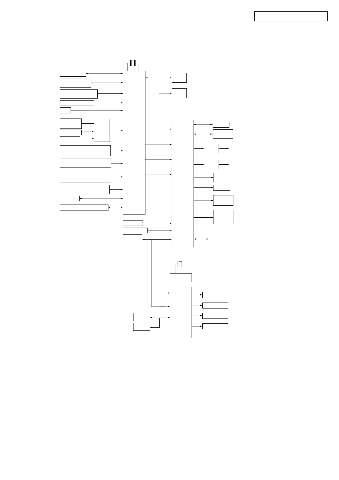
2.2 Engine Controller Board (K7N PWB)
28MHz
MB CONFIDENTIAL
OPTION TRAY
PAPER THICKNESS
SENSOR
COROR REGISTRATION
SENSOR
HEAT ROLLER TEMP
OHP
TEMPATURE
HUMIDITY
HEAD TEMP
DENSITY
COVER OPEN
(UPPER, STACKER, RIGHT SIDE)
1ST TRAY SENSORS
(PAPER END, PAPER NEAR END)
PAPER FEED SYSTEM SENSORS
(PAPER FEED, PAPER
REGISTRATION, EJECT)
MT SENSORS
(STAGE POSITION, PAPER END)
DUPLEX
DISPOSAL TONER SENSOR
ANALOG
SW
CPU
MSM66Q577
PAPER SIZE
STACKER FULL
CU
INT
CLK
RESET
FLASH
SRAM
MCON
LSI
EEPROM
CONTROL
PANEL
MOTOR
DRIVER
MOTOR
DRIVER
PULSE
MOTOR *9
GEARED
MOTOR
CLUTCH
PU FAN
FUSER FAN
ID, BELT,
FUSER
CHECKS
HIGH VOLTAGE POWER
SUPPLY SERIAL INTERFACE
32MHz
CLOCK
GENERATOR
LED HEAD (K)
LED HEAD (Y)
LED HEAD (M)
LED HEAD (C)
SDRAM
SDRAM
DCON
LSI
Figure 2-3
The engine control block (PU) is controlled by the engine controller board (K71 PWB) which
consists of a CPU (MSM66Q577), general LSI chip, flash ROM, EEPROM, pulse motor drivers and
a video memory (see Figure 2-3).
(1) CPU
This, a 16-bit CPU with an AD converter (MSM66Q577), controls the entire system.
(2) General LSI
This LSI (UPD65454GD-241-LML, UPD65946GD-137-LML), which is contained in the
printer engine control block, incorporates 4 megabits of video memory and has functions
such as engine-controller interfacing, LED interfacing, motor control, sensor input, video
memory control, main scan color misalignment correction, skew correction and high-voltage
power supply control.
41955801TH Rev.1 16 /

MB CONFIDENTIAL
(3) MCON LSI
This LSI is used for inport of SENSORs and the cntrols of Pulse Motors,Cluches,FANs and
High Voltage Power Suply.
(4) Flash ROM
The flash ROM (29F800-70) is of 8-Mbits, and PU programs are stored in it.
(5) EEPROM
The EEPROM (NM93C66N-NW) is of 4-Kbits, and mounted on the board with an IC socket.
Correction values are stored in it.
(6) Pulse Motor Driver
The pulse motor driver (A2919SLBTR, A3955SLBTR,MTD2005) drives the eight pulse
motors to revolve the ID and transport media.
(7) SRAM
This SRAM (628100LG-55L) is used as working memory of the CPU.
(8) SDRAM
This SRAM (56V16160T) is used as data memory of the DCON LSI.
2.3 Power Units
There are a low voltage power unit consists of an AC filter circuit, low voltage power circuit and
heater driver circuit, and a high voltage power unit organizes a high voltage power circuit.
(1) Low Voltage Power Unit
This circuit generates the following voltages:
Output Voltage Use for
+5 V LED head
+5 V Logic circuit power supply, PU CPU
+34 V Motor, drive voltage and power supply voltage for high voltage power supply
+12 V High voltage power supply, Media Thickness Sensor power supply
(2) High Voltage Power Unit
This circuit generates the following voltages of not less than +34V, which are required for
electrophotographic process, according to control sequences from the controller board.
Output Voltage Use for Remark
CH -1000V to 1.4KV+/-50V Voltage to charging roller
DB -50 to -300V/ +300V Voltage to developing roller
SB -300V to -450V/ 0V Voltage to toner supplying roller
TR C: 0KV to 7KV Voltage to transfer roller Variable
K,Y,M: 0KV to 6KV
41955801TH Rev.1 17 /
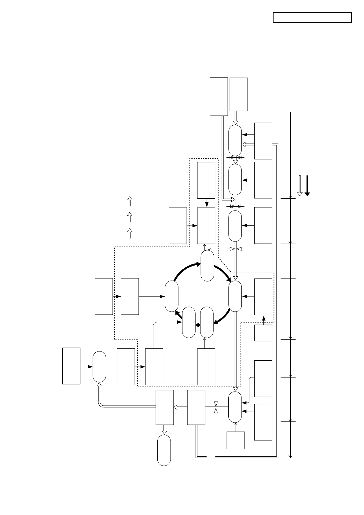
2.4 Mechanical Processes
Paper Eject Roller
Pape
ejection
(Face down)
Power Supply
Charging Roller
Cleaning Blade
Heat Roller
Paper
Eject
Roller
Fusing
Backup Roller
Control Signals
LED Head
Developing Roller
Power Supply
Toner Cartridge
Transfer Roller
Paper
registration
Registration
Roller 1
Paper loading
Hopping Roller
Power
Supply
Registration
Roller 2
Paper ejection Fusing Cleaning Transfer
Paper transport Paper advance
Transfer
Development
Paper Eject
Sensor
Paper Feed
Sensor 1
Paper Feed
Sensor 2
Paper Cassette
Paper
registration
(FF, 1ST, 2ND)
Write Sensor
×
4
K
YMC
Duplex printing
Paper path
selection
Paper path
selection
Paper traveling
OPC drum revolution
Charging
Exposure
Cleaning
Paper
ejection
(Face up)
Multipurpose Tray
Figure 2-4 shows the mechanical processes of the MB 716 of printer.
MB CONFIDENTIAL
41955801TH Rev.1 18 /
Figure 2-4

2.4.1 Electrophotographic process
(1) Electrophotographic process
The following is the outline of electrophotographic process:
1 Charging
DC voltage is applied to the charging roller and the surface of the OPC drum is negatively
and evenly charged.
2 Exposure
The LED head, under image signals, emits light to the negatively charged surface of the
OPC drum. The radiated portions of the drum surface attenuate in negative charge
according to the intensity of the light and, based on the surface potentials, a latent
electrostatic image is formed on the drum surface.
3 Development
Negatively charged toner contacts the OPC drum and by electrostatic force adheres to
the latent electrostatic image to form a clear image on the drum surface.
MB CONFIDENTIAL
4 Transfer
Placed on the surface of the OPC drum, paper is positively, or opposite to the polarity of
the toner, charged by the transfer roller on its back to transfer the toner image to the paper.
5 Cleaning
The cleaning blade removes residual toner from the OPC drum after the transfer.
6 Fusing
The toner image on the paper is fused into place through the application of heat and
pressure to it.
41955801TH Rev.1 19 /
MB CONFIDENTIAL
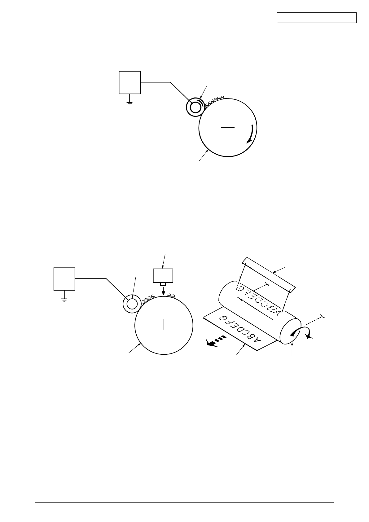
(2) Charging
Negative DC voltage is applied to the charging roller contacting the surface of the OPC drum.
Power
unit
Charging roller
OPC drum
(3) Exposure
The negatively charged surface of the OPC drum is radiated with light from the LED head.
The negative charge of the radiated portions of the drum surface attenuates in response to
the intensity of the light and a latent electrostatic image responsive to the potentials of the
surface is formed on the drum surface.
LED head
Power
unit
Charging roller
OPC drum
Paper
LED head
OPC drum
41955801TH Rev.1 20 /
MB CONFIDENTIAL
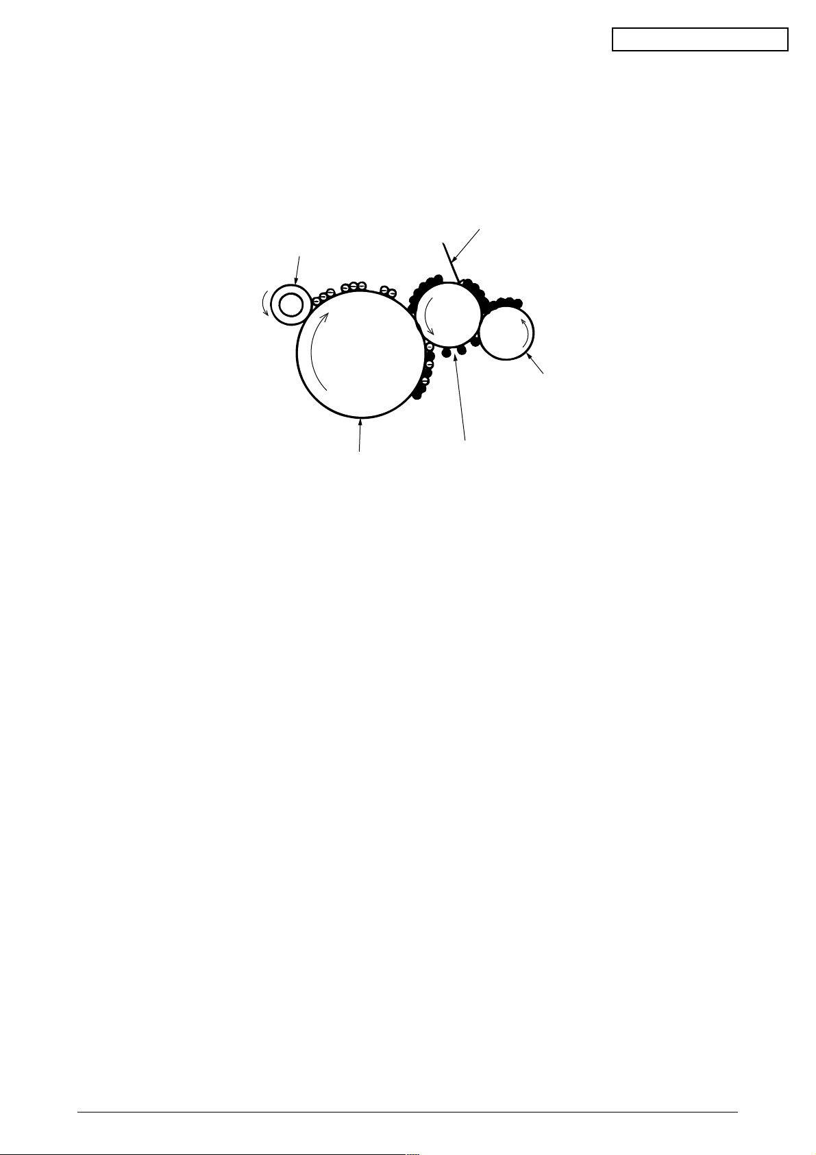
(4) Development
By the adhesion of toner to the latent electrostatic image on the drum surface, the image is
changed to an image of its toner. The development is processed at the contact portion
between the OPC drum and the developing roller.
1 The sponge roller causes toner to adhere to the developing roller. The toner becomes
negatively charged.
Developing blade
Charging roller
Sponge roller
OPC drum
Developing roller
2 The developing blade removes excess toner from the developing roller and a thin layer
of toner remains and forms on the developing roller.
3 The toner is drawn by the latent electrostatic image at the contact portion between the
OPC drum and the developing roller.
The latent electrostatic image on the drum surface is made visible with the toner.
41955801TH Rev.1 21 /
MB CONFIDENTIAL
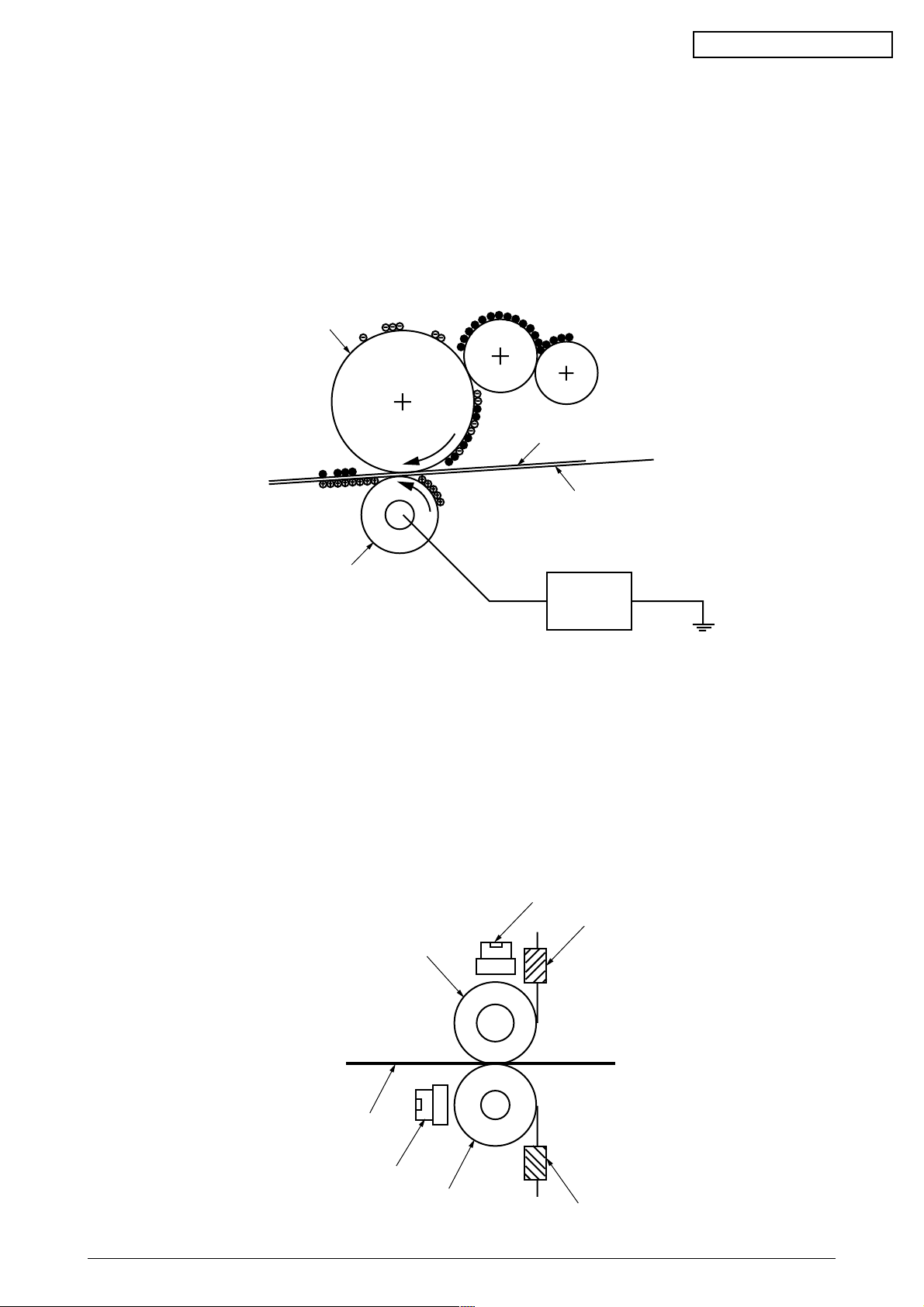
(5) Transfer
The transfer roller, which is made of conductive sponge, presses paper against the surface
of the OPC drum and brings the paper into intimate contact with the drum surface.
The paper is placed on the drum surface, and positively (opposite to the charge of the toner)
charged by the transfer roller on its back.
Applying positive high voltage from the power supply to the transfer roller moves the positive
charge induced by the transfer roller to the paper surface at the contact portion between the
transfer roller and the paper, the paper surface drawing the negatively charged toner from
the drum surface.
OPC drum
Paper
Transport belt
Transfer roller
Power unit
(6) Fusing
When passing through between the heat roller and the backup roller, the toner image
transferred to the paper is fused into place by the application of heat and pressure to it.
The built-in upper and lower halogen lamps of 700 watts and 500 watts heat the Teflon coated
heat roller. The fusing temperature is controlled by the sum of the temperature detected by
the thermistor moving over the heat roller surface and the temperature detected by the
thermistor moving over the backup roller surface. For safety, a thermostat is provided and,
when the heat roller temperature rises by a fixed degree or more, becomes open to cut off
voltage supply to the heater. The backup roller is being pressed against the heater by the
pressure springs on both sides.
Thermostat
Thermistor
Heat roller
Paper
Thermostat
Backup roller
41955801TH Rev.1 22 /
Thermistor
MB CONFIDENTIAL
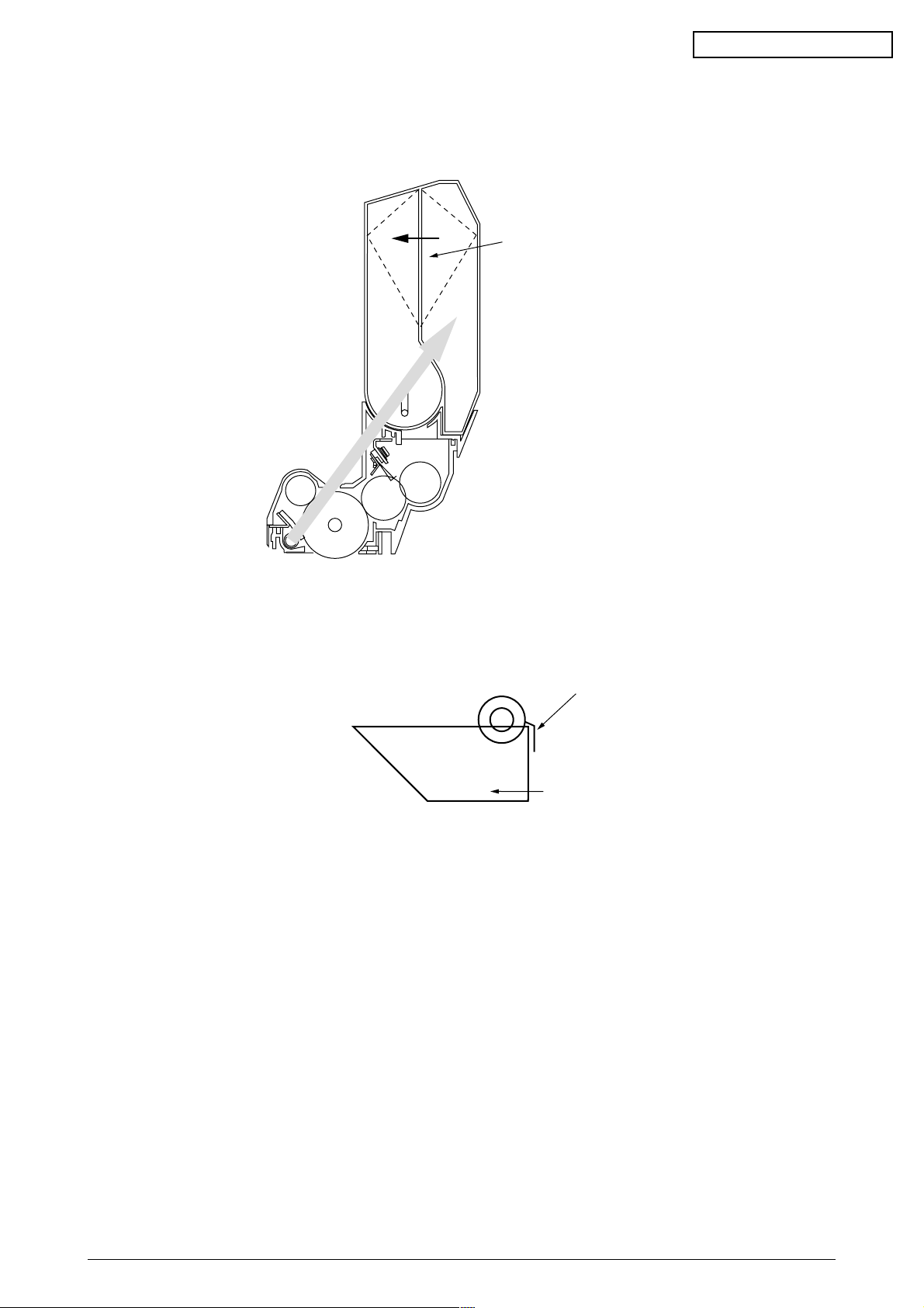
(7) Cleaning
Non-fused, residual toner on the OPC drum is scraped with the cleaning blade and collected
in the waste toner area of the toner cartridge.
flexible Waste toner area
( This area will be expanded by waste toner. )
(8) Cleaning
Residual toner on the transfer belt is scraped with the cleaning blade and collected in the
waste toner box of the transfer belt unit.
Cleaning blade
Waste toner box
41955801TH Rev.1 23 /
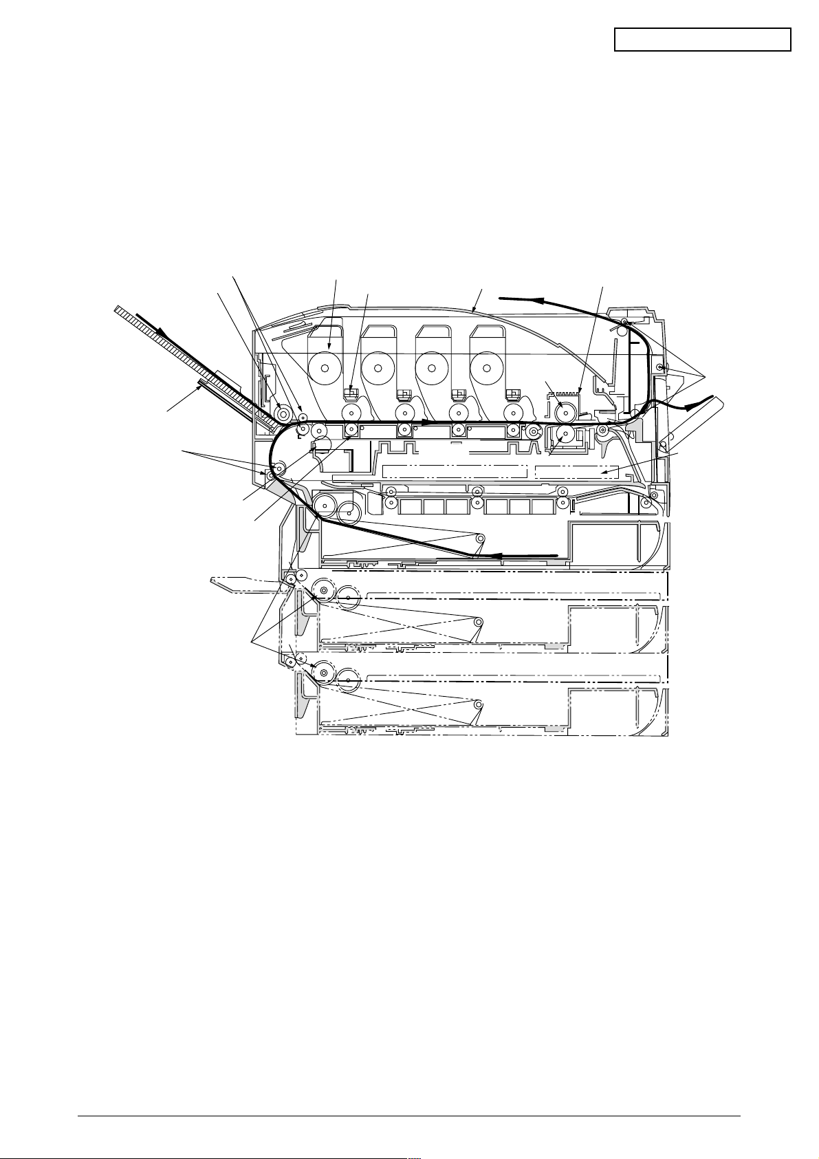
2.4.2 Paper running process
Figure 2-5 shows the traveling of paper in the MB 716 of printer.
MB CONFIDENTIAL
Registration roller Assy (B)
Hopping roller
Multipurpose tray
Registration roller Assy (A)
Cleaning blade
Transfer roller ×4
Feed roller
Unit × 4
Head × 4
High voltage power supply
Face-down stacker
MYK
Belt unit
Heat roller
C
Backup roller
Cassette 1
Cassette 2
Fuser
Eject roller
Low voltage
power supply
Figure 2-5 Paper Paths
Cassette 3
41955801TH Rev.1 24 /
MB CONFIDENTIAL
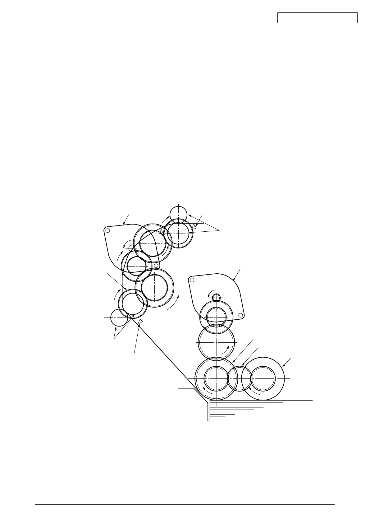
(1) Paper Feed from Tray
1. The running of the feed motor in the arrow direction (a) drives the feed roller and the
nudger roller. This operation feeds paper from the tray.
2. After the beginning of the paper turns the entrance cassette sensor on, the paper is
advanced a fixed length. When the paper beginning reaches the registration roller Assy
(A), the feed motor stops.
3. The running of the registration motor in the arrow direction (b), which synchronizes with
the above paper advance operation, drives the registration roller Assy (B) and the
electromagnetic clutch. The registration roller Assy (A) moves with the operation of the
electromagnetic gear when the paper beginning touches the registration roller Assy (A),
where the feed motor does not run. The feed roller idles via the built-in one-way clutch
and the nudger roller idles because the planet gear is disengaged.
4. The registration motor transports the paper until the paper end passes through the
entrance belt sensor.
Registration motor
Electromagnetic clutch
Registration roller
Assy (A)
Entrance cassette sensor
Entrance belt sensor
Registration roller
b
Assy (B)
Feed motor
a
Feed roller
(One-way clutch gear)
Paper gear
Nudger roller
Paper
Figure 2-6
41955801TH Rev.1 25 /
MB CONFIDENTIAL
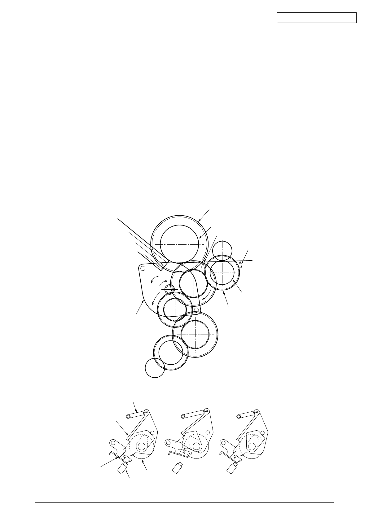
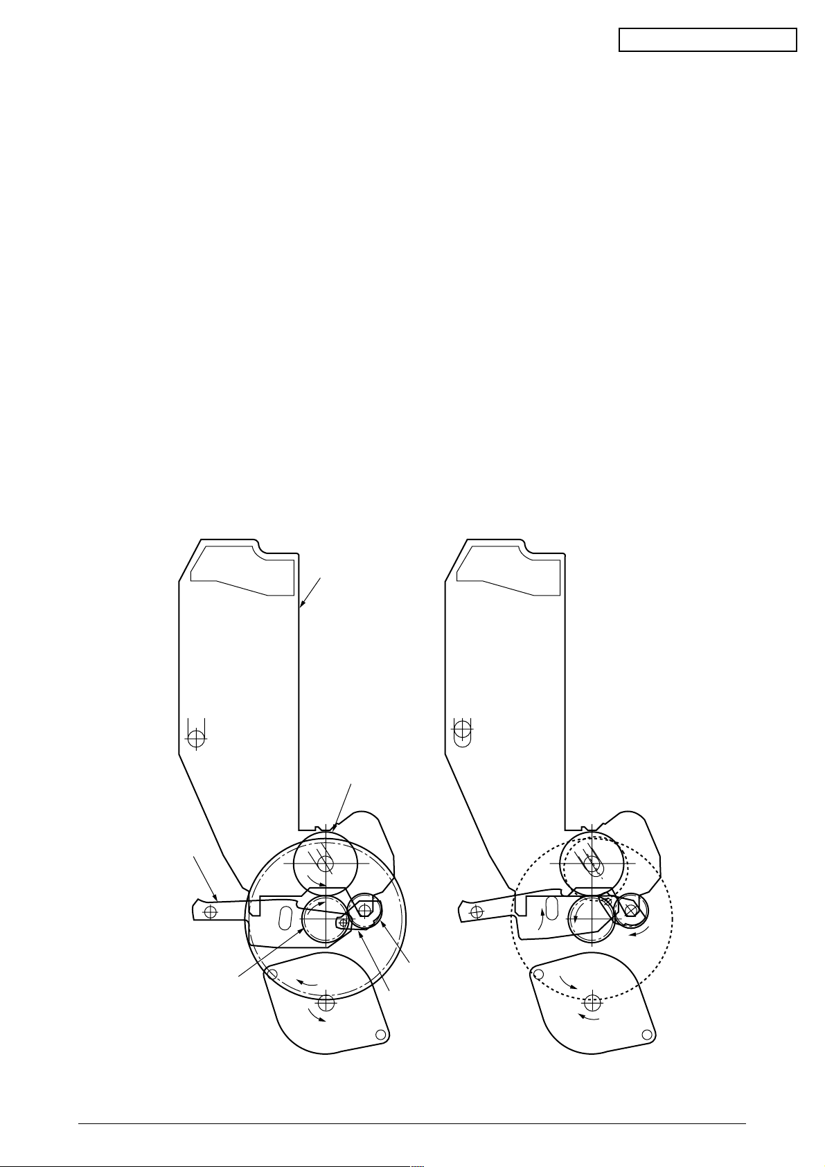
(2) Paper Feed from Multipurpose Tray (MT)
1. The release lever usually pushes down the hopping plate to a position that turns
microswitch on (Figure 2-7-a).
2. The running of the motor in the (a) direction drives the MT feed roller and turns the cam.
The cam pushes the release lever and the hopping plate picks up paper sent out by the
MT feed roller (Figure 2-7-b), where the registration roller Assy (B) does not move
because its one-way clutch gear (1) idles.
3. After the paper beginning turns the entrance sensor on, the paper is forwarded a fixed
length. The paper stops when its beginning reaches the registration roller Assy (B).
4. At the same time, the cam pushes down the hopping plate. The release lever that has
been placed in its original position by the spring locks the hopping plate (Figure 2-7-c).
5. After the completion of the paper feed operation, the registration motor runs in the arrow
direction (b) to drive the registration roller Assy (B), where the one-way clutch gear (2)
does not allow the MT feed roller to move.
Paper
b
Registration motor
One-way clutch gear (2)
MT feed roller
Entrance sensor
Entrance belt sensor
a
Registration roller Assy (B)
One-way clutch gear (1)
Figure 2-7
Spring
Release lever
Hopper plate
Feed roller
Microswitch
Figure 2-7-a Figure2-7-b Figure 2-7-c
41955801TH Rev.1 26 /
MB CONFIDENTIAL
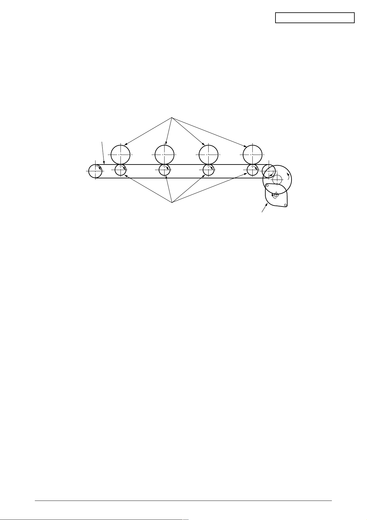
(3) Transport Belt
1. The running of the transport belt motor in the arrow direction (a) drives the transport belt.
The belt unit sits with one transport roller immediately below each color’s drum, and the
transport belt between them. By the application of a fixed voltage, the transport belt and
the transport roller feed paper on the transport belt into the fuser unit, transferring a toner
image on each color’s drum.
Drum
Transport belt
KYMC
Transport (transfer) roller
Figure 2-8
Transport (transfer) belt motor
41955801TH Rev.1 27 /
MB CONFIDENTIAL
(4) Driving and Up-and-Down Movements of I/D Unit
1. The I/D unit driving and up-and-down movements are effected by a single-pulse motor.
The running of the main motor in the arrow direction (a) turns the lever 1 to the left. Then,
the lever 2 that was lifted by the lever 1 lowers to move down the I/D unit. After the up/
down sensor is turned off (Figure 2-9-d), specified downward pulsing places the I/D unit
in its lowest position, or equivalently, printing position (Figures 2-9-a and 2-9-c).
The drum gear engages with the driving gear and starts revolving to transfer an image on
the drum to running paper, where the one-way gear idles upon placement of the lever in
its lowest position.
2. With the running of the main motor in the arrow direction (b), the lever 1 pushes up the
I/D unit via the lever 2. After the up/down sensor is activated (Figure 2-9-d), the lever 1
lifts the I/D unit to a specified level and stops to keep space to an extent between the drum
and the transport belt (Figures 2-9-c and 2-9-e).
The drum gear is not engaged with the driving gear and does not revolve.
3. When the two pins of the up/down sensor are pushed up by the I/D unit, and touches and
electrically connected to the plate above the pins, the sensor recognizes the on state.
When the two pins are pushed down by the I/D unit, and separated and insulated from the
plate, the sensor recognizes the off state.
The installation of the I/D unit can also be verified by recognizing the off state of the up/
down sensor.
Lever 2
Driving gear
I/D unit
a
Drum
One-way gear
Lever 1
b
Figure 2-9-a Figure 2-9-b
41955801TH Rev.1 28 /
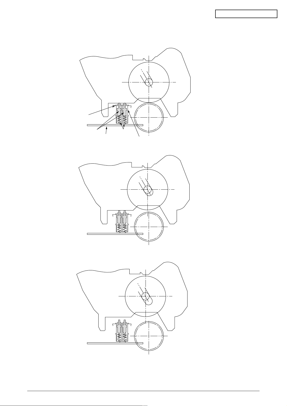
Plate
Pin Spring
Board
MB CONFIDENTIAL
Up/down sensor
Figure 2-9-c
Figure 2-9-d
Figure 2-9-e
41955801TH Rev.1 29 /
MB CONFIDENTIAL
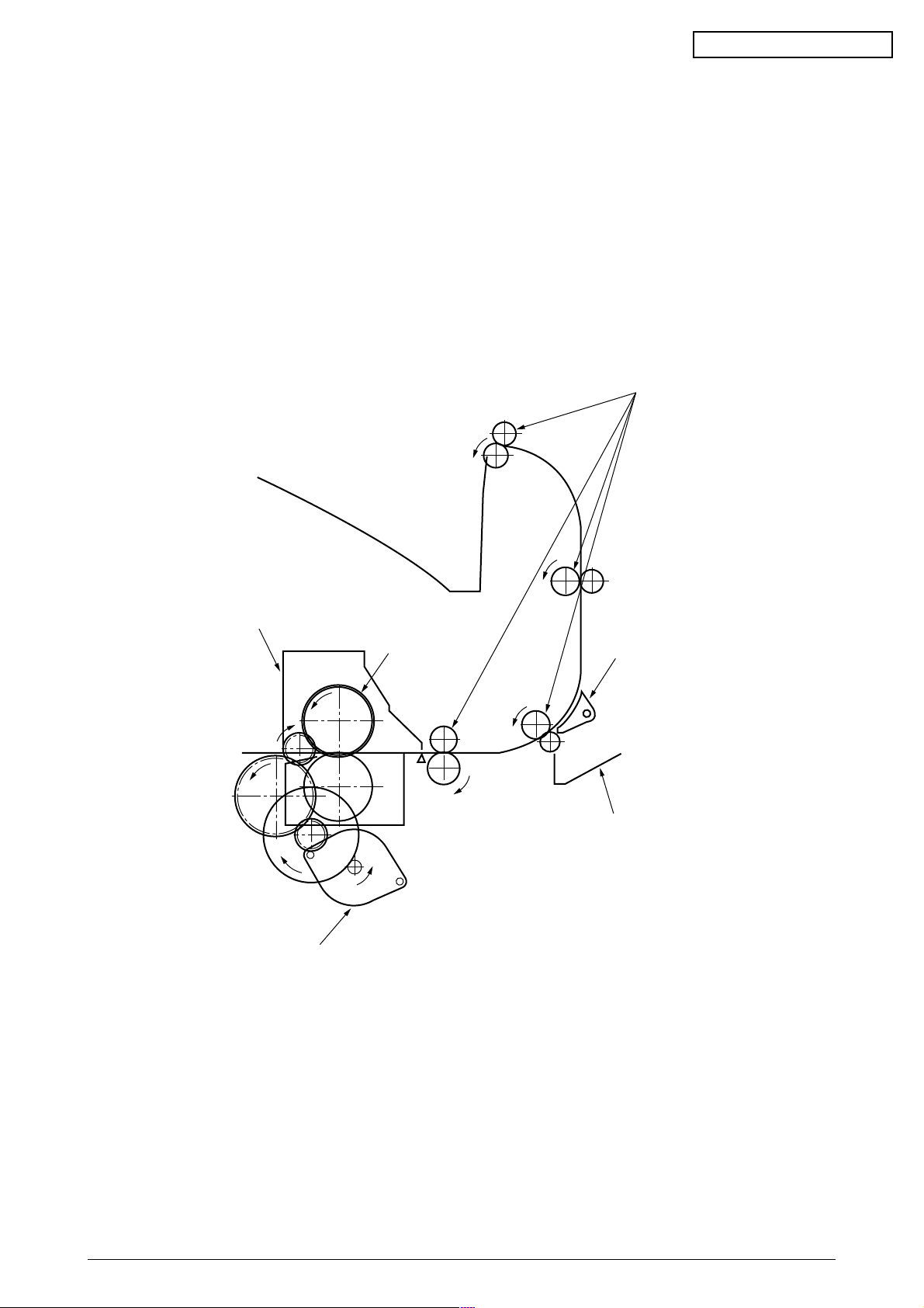
(5) Fuser Unit and Paper Ejection
1. A single-pulse motor drives the fuser unit and the eject rollers.
In response to the running of the heat motor in the arrow direction (a), the heat roller turns.
This roller fuses a toner image to paper by heat and pressure.
2. At the same time, the four eject rollers move to eject the paper.
3. The ejection path is switched back and forth between the route to the face-up stacker and
the route to the face-down stacker as follows. When the face-up stacker opens, the paper
separator inclines in the direction that guides the paper to the face-up stacker. When the
face-up stacker closes, the paper separator inclines in the direction that sends the paper
to the face-up stacker.
Eject rollers
Fuser unit
Heater motor
Heat rollers
a
Figure 2-10
Paper separator
Face-up stacker
41955801TH Rev.1 30 /
MB CONFIDENTIAL
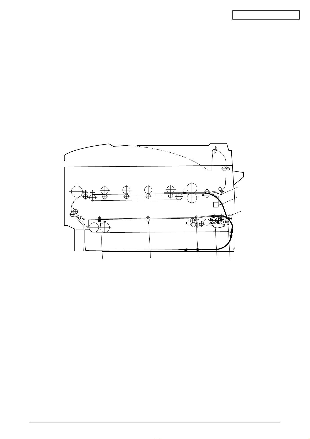
(6) Duplex Unit
1. When the duplex unit receives an instruction from the printer to print on both sides of a
sheet of paper, the solenoid opens the separator after the completion of one side printing
of a sheet of paper sent from the tray. The path is switched to that to the duplex unit.
At this time, as the roller (1) turns in the direction of the arrow “a,” the paper is retracted
on the rear of the cassette.
2. When fixed time has elapsed after the paper beginning passes through the duplex-in
sensor, the rollers reverse and the roller (1) turns in the direction of the arrow “b” to feed
the paper into the duplex unit. After that, the paper passes through the rollers (2), (3) and
(4), and ejected with the other side printed, and fed again into the printer.
Figure 2-11
Separator
Solenoid
Duplex-in sensor
b
a
Motor
Roller(2)Roller(3)Roller(4)
Roller(1)
41955801TH Rev.1 31 /
 Loading...