

Page 1

Training Manual
Basic Climate Control
CT-L1005
Page 2

No part of this hardcopy may be reproduced in any form without prior permission of
Mazda Motor Europe GmbH.
The illustrations, technical information, data and descriptive text in this issue, to the best of our
knowledge, were correct at the time of going to print.
No liability can be accepted for any inaccuracies or omissions in this publication, although every
possible care has been taken to make it as complete and accurate as possible.
© 2005
Mazda Motor Europe GmbH
Technical Services
Page 3

Basic Climate Control Table of Contents
Introduction .......................................................................................01-1
Fundamentals....................................................................................02-1
Physical Comfort....................................................................................... 02-1
Getting Comfortable............................................................................ 02-2
Changing the Air Temperature ........................................................... 02-2
Warming the Air in the Vehicle ........................................................... 02-4
Cooling the Air in the Vehicle.............................................................. 02-5
Latent Heat......................................................................................... 02-6
Dehumidifying the Air.......................................................................... 02-8
Filtering the Air ................................................................................... 02-9
Refrigerant.............................................................................................. 02-10
Pressure-Temperature Relationship of R134a ................................. 02-10
Refrigerant in a Closed Container..................................................... 02-11
Handling Refrigerant......................................................................... 02-12
Environmental Impact.......................................................................02-12
Compressor Oil.......................................................................................02-13
Moisture in the A/C System..................................................................... 02-13
A/C System ........................................................................................03-1
System Overview......................................................................................03-1
A/C System with Expansion Valve...........................................................03-3
Parts Location...........................................................................................03-3
Compressor .............................................................................................. 03-4
Vane Rotary Compressor................................................................... 03-5
Scroll Compressor.............................................................................. 03-6
Swash Plate Compressor................................................................... 03-7
Condenser ................................................................................................ 03-8
Fin and Tube Condenser....................................................................03-9
Multiflow Condenser......................................................................... 03-10
Multiflow Condenser with Sub-cooler................................................ 03-11
Receiver / Drier.......................................................................................03-12
Expansion Valve..................................................................................... 03-14
Evaporator .............................................................................................. 03-16
Refrigerant Lines..................................................................................... 03-19
Control .................................................................................................... 03-20
Refrigerant Pressure Switch............................................................. 03-20
Low / High Pressure Switch.............................................................. 03-20
Medium Pressure Switch..................................................................03-21
Magnetic Clutch................................................................................ 03-21
Wiring Diagram................................................................................. 03-22
Curriculum Training
Page 4

Table of Contents Basic Climate Control
A/C System with Fixed Orifice.......................................................................... 03-23
Parts Location.........................................................................................03-23
Compressors........................................................................................... 02-24
Variable Displacement Swash Plate Compressor ............................ 03-24
Variable Displacement Scroll Compressor ....................................... 03-25
Fixed Orifice ..................................................................................... 03-25
Accumulator / Drier........................................................................... 03-27
Control .................................................................................................... 03-28
A/C Cycling Switch ........................................................................... 03-28
Refrigerant Pressure Switch............................................................. 03-29
Wiring Diagram................................................................................. 03-30
Component Overview ............................................................................. 03-31
Heating System .................................................................................04-1
System Overview......................................................................................04-1
Thermostat................................................................................................ 04-2
Heater Core .............................................................................................. 04-2
Water Pump..............................................................................................04-2
Radiator .................................................................................................... 04-2
Diagnosis and Repair........................................................................05-1
Pressure Gauges......................................................................................05-1
Refrigerant Pressure Check ............................................................... 05-2
Leak Testing ............................................................................................. 05-4
Control System Check .............................................................................. 05-5
A/C Service Machine ................................................................................ 05-5
Draining the A/C System .................................................................... 05-6
Evacuating the A/C System................................................................ 05-6
Filling the A/C System ........................................................................ 05-6
Summary of Refrigerant Draining and Filling Procedures................... 05-7
Component Replacement ......................................................................... 05-8
Compressor Damage................................................................................ 05-9
Odours from the A/C System.................................................................... 05-9
Diagnosis on the Heating System...........................................................05-10
Thermostat ....................................................................................... 05-10
Heater Core...................................................................................... 05-10
Curriculum Training
Page 5

Basic Climate Control Introduction
Introduction
• A/C (Air Conditioning) has been available for automobiles since the 1930’s. Here in
Europe in the last five years there has been a large increase in the number of vehicles
equipped with A/C. This course does not just cover air conditioning, but also the heating
system, hence the name Basic Climate Control. The climate control system in a vehicle
does not only ensure the comfort of the passengers, there is also a safety aspect.
Without a properly functioning climate control system, it might not be possible to keep
the windscreen free from misting up during damp or cool weather.
• Mazda uses two different A/C systems on its vehicles; a system using an expansion
valve, and a system using a fixed orifice. The components and operation of both systems
will be covered.
• The majority of Mazda vehicles currently sold in Europe are equipped with an A/C
system. On some models A/C is standard.
• Diagnosing and repairing climate control system related concerns requires working with
a refrigerant under pressure. Improper handling of the refrigerant could lead to serious
injuries. Follow the safety guidelines both here in this training manual, and in the service
literature. This course is a theoretical and practical guide to gain general and Mazda
specific knowledge about the different climate control systems, including their
components, function, and diagnosis.
• Anyone associated with the diagnosis and repair of climate control systems must have
the knowledge to deliver a “Fix it right first time” repair. Therefore, the Mazda Masters
development and qualification path provides the following training courses required for
servicing and diagnosing climate control systems:
– Basic Climate Control CT-L1005
– Advanced Climate Control CT-L2009
• The ranking of this course within the Mazda Masters educational system is Level 1 –
‘Mazda Technician’. It is intended for technicians who already have experience in
maintaining and repairing Mazda vehicles and have previously attended the course
“New-To-Mazda” CT-L1001.
Curriculum Training 01-1
Page 6

Introduction Basic Climate Control
• The training manual “Basic Climate Control” is divided into the following main chapters:
– Fundamentals
– A/C System
– Heating System
– Diagnosis and Repair
NOTE: The data, tables, and procedures presented in this training manual serve only as
examples. They are taken from the service literature and subjected to major or minor
changes over the course of time. To prevent any mis-diagnosis, always refer to the
current service literature while working on climate control systems.
01-2 Curriculum Training
Page 7
Basic Climate Control Fundamentals
Fundamentals
Physical Comfort
• When do we feel comfortable? What is comfort? When we aren’t comfortable, how can
we become comfortable?
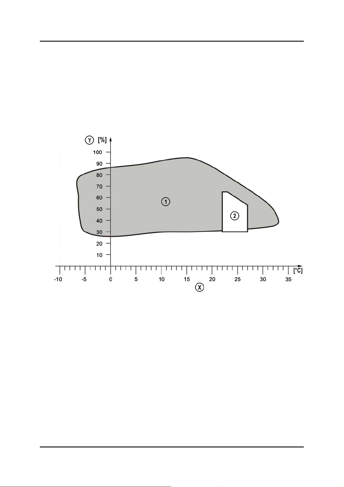
• There is a norm that shows where most people find it comfortable based on the air
temperature, and relative humidity. There are also other factors not shown on this graph
that affect our comfort, such as how clean the air is and if there is an unpleasant
draught, or perhaps a pleasant breeze.
L1005_044
X Temperature Y Relative humidity
1 This area represents 90% of all outside
conditions
2 This area shows the ‘comfort zone’
Curriculum Training 02-1
Page 8

Fundamentals Basic Climate Control
Getting Comfortable
• To change the level of comfort in a building there are several possibilities: open a
window, turn on a fan, adjust the thermostat, take some clothes off, or put some clothes
on. While it’s possible to do all of these things in a vehicle, there are of course practical
limitations. When driving in the rain, opening a window becomes impractical. The driver
of the vehicle might also find it difficult to keeping taking clothes off, and putting clothes
on.
• So a vehicle has a climate control system to allow the driver to create a comfortable
climate. To allow the driver to do this it has to be possible to change the two main factors
that affect our comfort: temperature and humidity. At the same time the air needs to be
cleaned, and the direction and speed of the air stream must be controllable.
Changing the Air Temperature
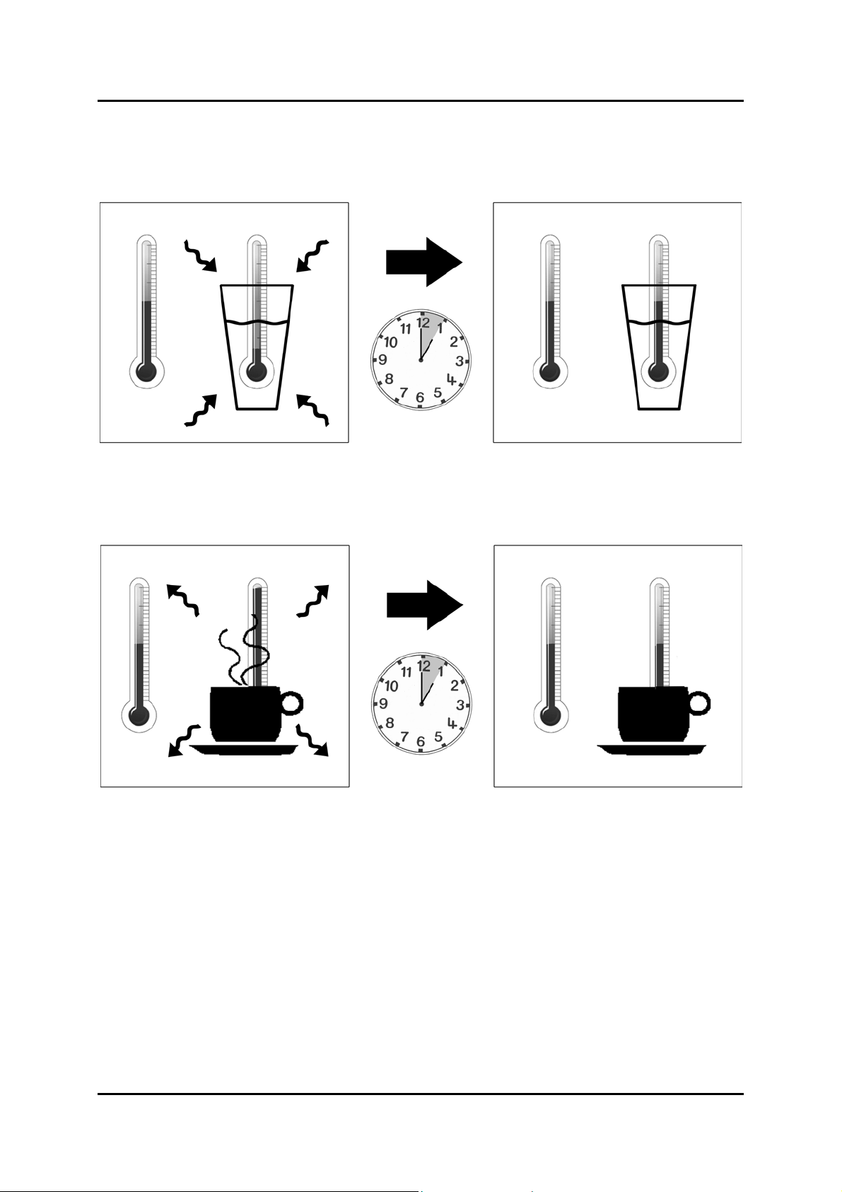
• The air entering the vehicle can be warmed, or the warmth can be taken from it. There is
no way to create ‘cold’. It is important to keep in mind that heat always travels from
warm to cold. The two following examples illustrate this fact.
02-2 Curriculum Training
Page 9
Basic Climate Control Fundamentals
• In the first example a cold glass of water is brought into a warm room. The water will
absorb some of the heat from the air in the room, and settle to the ambient temperature
of the room. The heat travels from the warmer surroundings to the cooler water.
L1005_001
• In the second example a hot cup of coffee is brought into a warm room. The coffee gives
off the heat to the air in the room, and will settle to the ambient temperature of the room.
The heat travels from the hot coffee to the cooler surrounding air.
L1005_002
Curriculum Training 02-3
Page 10
Fundamentals Basic Climate Control
Warming the Air in the Vehicle
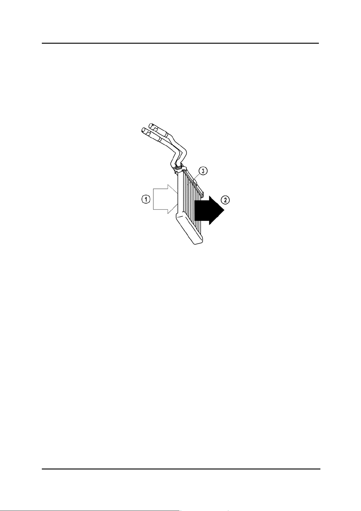
• To carry the second example across to the vehicle, think of the heater core as the cup of
coffee being brought into a relatively colder room. The heater core gives its heat up to
the outside air that comes in contact with the fins. The heat travels from the warm heater
core to the cold air. Unlike the coffee in our example, the heater core receives a
continuous flow of hot coolant from the engine, and so will continue to give off heat as
long as the engine is running.
1 Cold air 3 Heater core
2 Warm air
L1005_004
02-4 Curriculum Training
Page 11
Basic Climate Control Fundamentals
Cooling the Air in the Vehicle
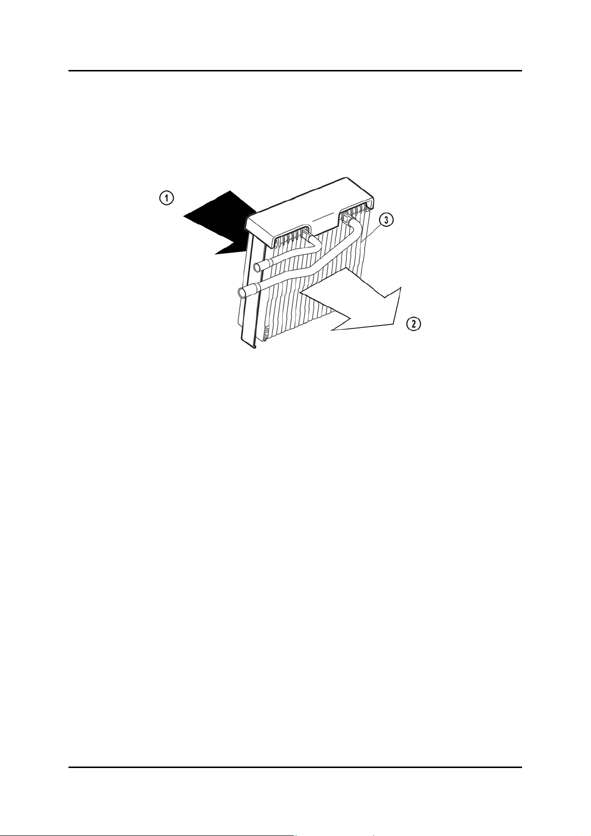
• The example of the cold glass of water can be partially compared to the evaporator. The
evaporator is filled with a cold liquid, and this liquid absorbs the heat from the air as it
comes in contact with the fins of the evaporator. The heat travels from the hot air to the
cold evaporator.
L1005_003
1 Warm air 3 Evaporator
2 Cold air
• This heat absorption process in the evaporator is a little more complicated than the
heating process in the heater core. As the refrigerant passes through the evaporator, it is
a low pressure, cold liquid. As the warm air comes in contact with the fins of the
evaporator, the heat from the warm air is conducted through the metal fins and warms
the refrigerant flowing through the internal passageways. This warmth causes the
refrigerant to boil. During this boiling process the heat energy from the hot air entering
the vehicle is transferred to the refrigerant.
• As the refrigerant leaves the evaporator is will be a low-pressure gas. The heat energy
absorbed was used to change its state from a liquid to a gas (to boil it). The end effect
for the air is that as it comes out the other side of the evaporator it is now colder. The
two physical principles that allow this are the latent heat of vaporization, and the
pressure-temperature relationship properties of the refrigerant.
Curriculum Training 02-5
Page 12

Fundamentals Basic Climate Control
Latent Heat
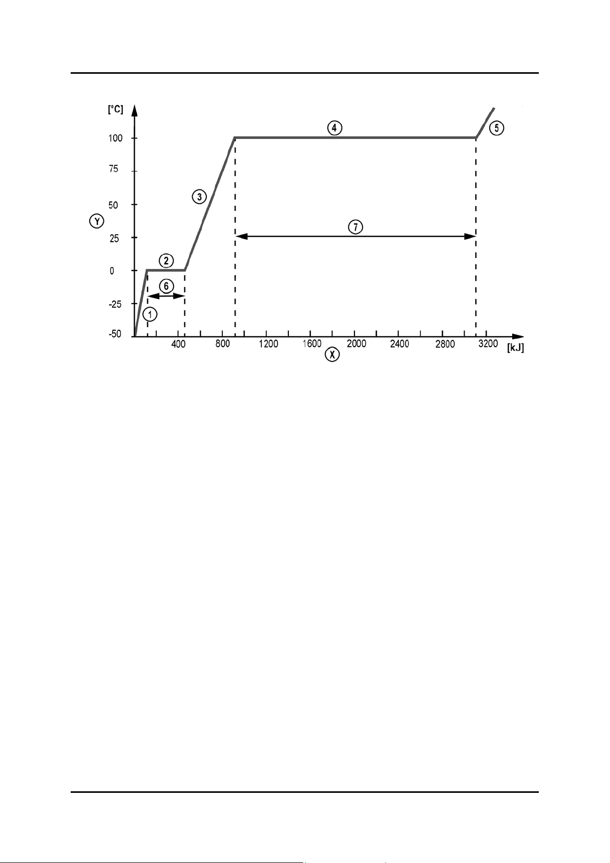
• The following graph shows the amount of heat added to 1 kg of water on the horizontal
axis, and on the vertical axis shows the temperature of the water. In the first stage the
water is frozen, and as heat is added to it, the temperature rises. As soon as the ice
reaches 0 °C it starts to melt. At this point all the heat energy is used to change the ice to
water; this is called the latent heat of fusion.
• Stage 2 shows that even though the entire energy (334 kJ) is added to the ice/water
mixture, the temperature does not change. Only when all of the ice is melted, does the
temperature start to rise again in direct relation to the amount of heat added (stage 3).
This is because the energy added is no longer required to change the ice to water, and
now the energy being added increases the temperature.
• At 100 °C the water starts to boil. At this point the temperature stops increasing, since all
the energy is needed to change the state from a liquid to a gas. This is known as the
latent heat of vaporization. This physical property is critical to the functioning of the
A/C. Stage 4 shows that the entire energy (2,258 kJ) is absorbed without increasing the
temperature of the water/steam mixture. This is the physical property that allows so
much heat to be taken from the warm air entering the vehicle.
02-6 Curriculum Training
Page 13
Basic Climate Control Fundamentals
X Heat energy Y Temperature
1 Ice being warmed 5 Steam being warmed
2 Ice changing to water 6 Latent heat of fusion
3 Water being warmed 7 Latent heat of vaporization
4 Water changing to steam
L1005_022
Curriculum Training 02-7
Page 14

Fundamentals Basic Climate Control
Dehumidifying the Air
• The air entering the vehicle normally has a relatively high humidity. When this humid air
comes in contact with the cool surface of the evaporator the moisture in the air will
condense as tiny droplets of water. These water drops will accumulate and run down the
evaporator, and leave the vehicle through the drain tube.
• There is no way to actively control how much moisture will be taken from the air, this is
determined by the dew point, which depends on the current air temperature and the
relative humidity of the air. Operating the A/C allows the evaporator to cool down, and for
the moisture in the incoming air to condense. This process can also be performed when
heating or defrosting, by turning the A/C on, and then selecting a warmer temperature.
This is especially effective when demisting or defrosting.
NOTE: This is the only one of the comfort factors that cannot be directly influenced by the
driver. The relative humidity can be indirectly reduced by operating the A/C and
forcing the humid air through the evaporator.
02-8 Curriculum Training
Page 15

Basic Climate Control Fundamentals
Filtering the Air
• A mostly forgotten aspect of our feeling of comfort is how clean the air is. When the air is
clean it feels comfortable even at warmer or colder temperatures than normal. Add to
that the number of people today suffering from allergies (such as a pollen allergy etc.),
and the benefit of a filter can quickly be seen.
• The filter in the HVAC (Heating, Ventilation, Air Conditioning) system filters both the
fresh air and the recirculated air. A certain amount of smaller particles that pass the filter
are also trapped in the condensed water, which accumulates on the evaporator.
NOTE: The cabin filters used in Mazda vehicles cannot be cleaned and must therefore be
replaced at certain intervals (see the workshop manual). But if a customer drives in
dusty areas, or often drives in heavy stop and go traffic, a more frequent change
interval might be required.
L1005_009
1 Unfiltered air 3 Filtered air
2 Air filter
Curriculum Training 02-9
Page 16
Fundamentals Basic Climate Control
Refrigerant
• The refrigerant used in current Mazda vehicles is called R134a. It is a hydrofluorocarbon
(C
with the fact that it does not harm the ozone layer, makes it an almost perfect substance
for A/C. However, R134a does still contribute to the greenhouse effect.
NOTE: Older Mazda vehicles use R12 refrigerant, which must not be used anymore. In
Pressure-Temperature Relationship of R134a
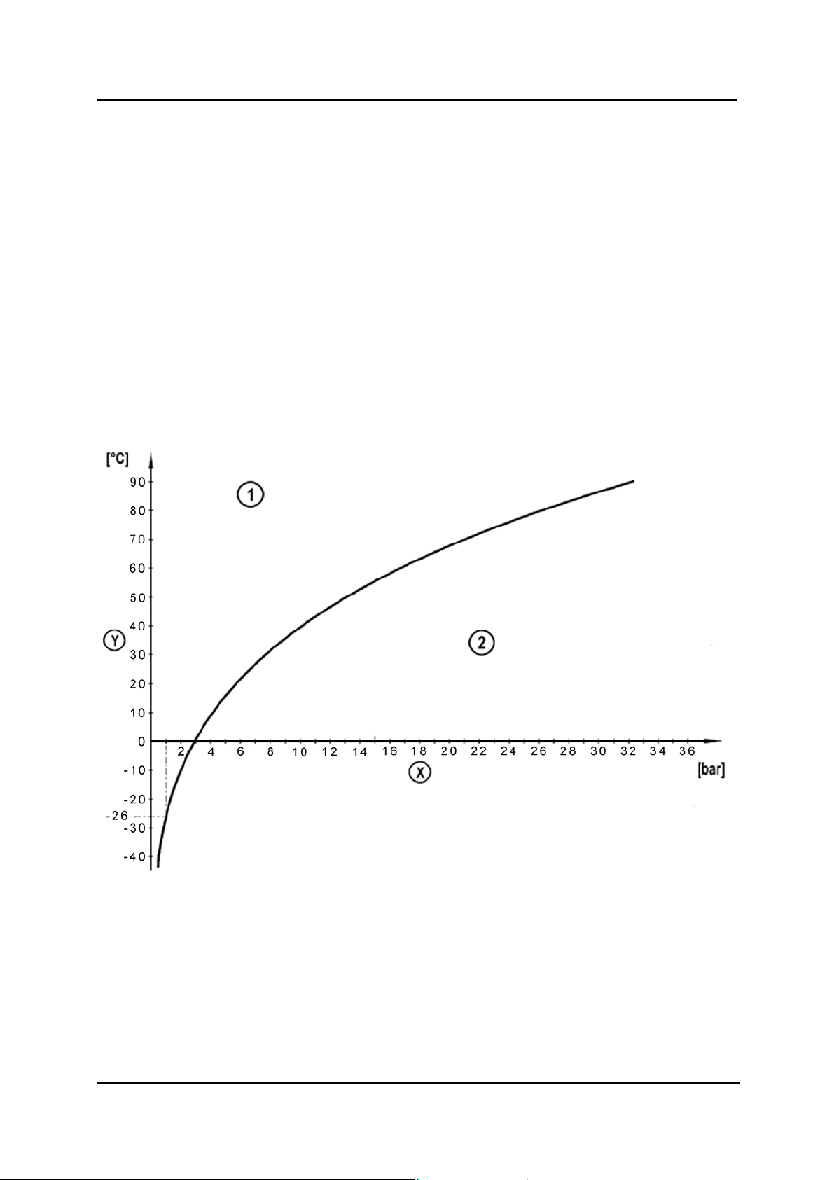
• This chart shows the relationship between pressure and temperature for the refrigerant.
At normal atmospheric pressure of 1 bar, refrigerant will boil at –26°C. Above this curve
(area 1 in the diagram) the refrigerant is gaseous, below the curve (area 2 in the
diagram) it is liquid.
) that at normal atmospheric pressure boils at –26°C. This property, combined
2H2F4
addition, R12 and R134a must not be mixed.
L1005_023
X Pressure Y Temperature
1 Gaseous refrigerant (above the curve) 2 Liquid refrigerant (below the curve)
02-10 Curriculum Training
Page 17
Basic Climate Control Fundamentals
Refrigerant in a Closed Container
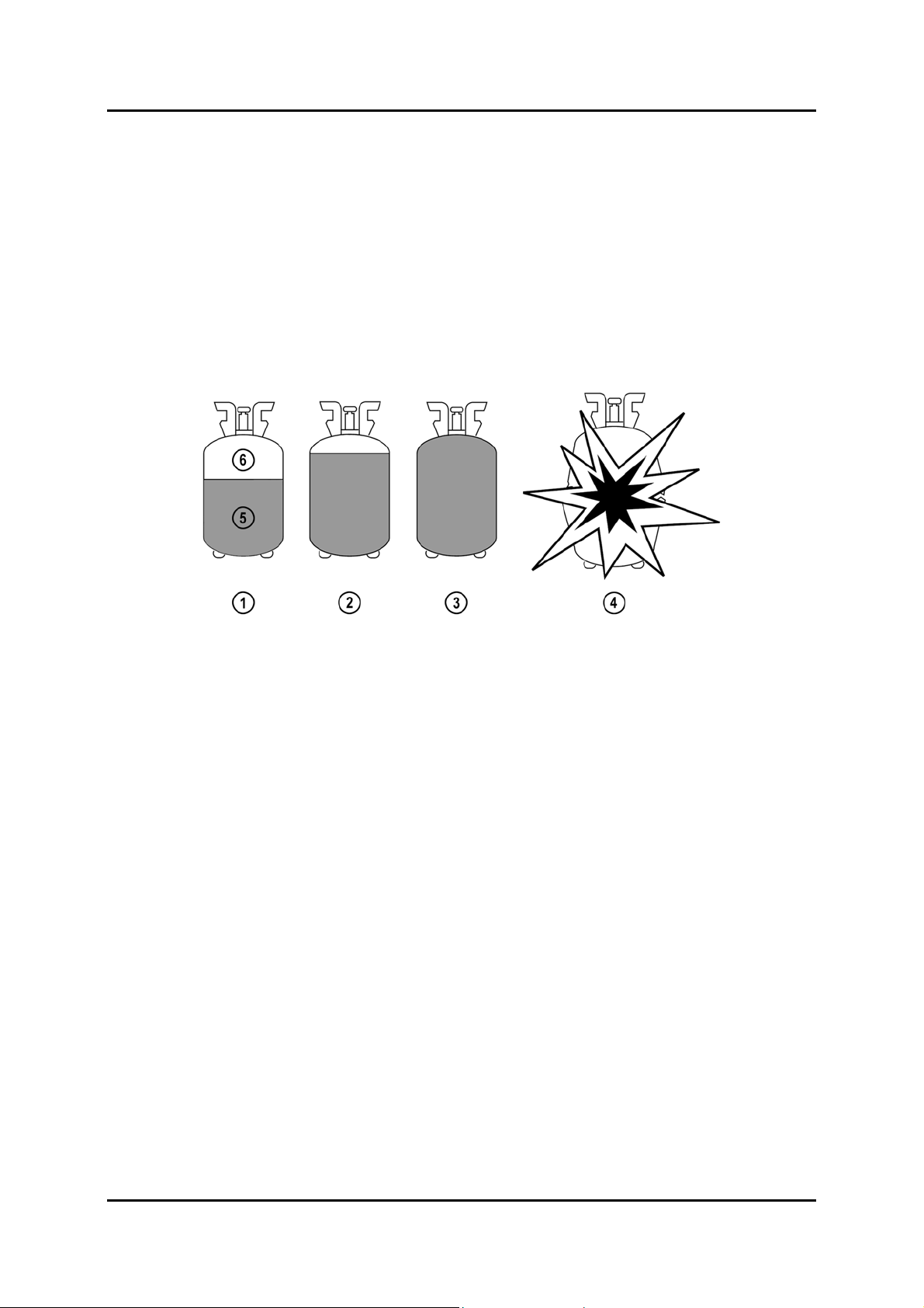
• When R134a is in a closed container, and the container is in a surrounding with an
ambient temperature above –26°C, some of the liquid will boil off until pressure is
developed. The pressure will be equal throughout the entire container, and the
developed pressure will keep a portion of the refrigerant liquid. As the container heats
up, the liquid refrigerant will expand in volume. If the container is allowed to warm up to
the point where the liquid has expanded to fill the entire volume of the container, the
pressure will then increase rapidly, and the container could rupture.
CAUTION: Filling a container more than 60%, and storing a container near sources of heat
or in direct sunlight can cause serious injury.
1 Properly filled container 4 Ruptured container
2 Overfilled / overheated container 5 Liquid refrigerant
3 Dangerously overfilled / 6 Gaseous refrigerant
overheated container
• In the event of a rupture, the resulting explosion is much more violent than say a
comparable rupture with compressed air. The refrigerant leaving the container will be
nearly instantaneously vaporized, causing a rapid increase in the volume of the
refrigerant. For this reason the containers are delivered with a liquid fill volume of no
more than 60% (at 20° C).
L1005_041
Curriculum Training 02-11
Page 18

Fundamentals Basic Climate Control
Handling Refrigerant
• Because R134a boils at –26°C, if a line is opened while there is refrigerant still in the
system, the refrigerant will boil by absorbing heat from the surrounding area. This means
that if your hand comes in contact with the refrigerant as it escapes, you will experience
acute frostbite (a strong burning sensation). To avoid this, insulated rubber gloves
should be worn. Normal cloth or leather gloves provide little protection, as the heat will
be absorbed through the material.
• Protective safety glasses should be worn to protect against dirt being blown into the eyes
in the event that a high-pressure line is opened.
• The A/C service equipment should be used in accordance with the manufacturers
instructions.
• Keep in mind that R134a is heavier than air and will sink to the ground, that means that
working in a pit or other low lying area while servicing the A/C is not recommended,
because large amounts of released refrigerant could displace the air, and cause
suffocation.
• While R134a is not flammable, it could develop into a toxic compound (hydrogen
fluoride) when it comes in contact with an open flame, electrical arcing, or a source of
extreme heat
Environmental Impact
• R134a is an improvement on its predecessor R12, but it still is harmful to the
environment. R134a does not contribute to depletion of the ozone layer like R12 did, but
it still contributes to the greenhouse effect. When one gram of R134a is released to the
atmosphere, it has the same effect as 1.2 kg of CO
For reference, 1 g of R12 has the same effect as 8.5 kg of CO
atmosphere.
• It should also be kept in mind that any R134a that is released into the atmosphere will,
on average, not break down for 14 years. While this is better than the 100 years it takes
R12 to break down, it is still not desirable.
being released to the atmosphere.
2
being released to the
2
02-12 Curriculum Training
Page 19

Basic Climate Control Fundamentals
Compressor Oil
• The compressor oil in the A/C circuit is required to lubricate the moving parts of the
compressor. The oil is carried throughout the system by the refrigerant. The compressor
oil is highly hygroscopic PAG (Poly-Alkaline Glycol), meaning it easily absorbs moisture
(much like brake fluid does).
NOTE: Older Mazda vehicles with R12 refrigerant use mineral compressor oil, which must
not be used anymore. In addition, mineral oil and PAG oil must not be mixed.
• The current range of Mazda vehicles all use PAG oils, but there are several different
types available. They can have differing characteristics such as different viscosity. For
this reason, the different compressor oils are not interchangeable. This means that when
servicing a vehicle, the correct oil needs to be put into the A/C system.
NOTE: Compressor oil needs to be properly disposed of just like any other environmentally
harmful fluids (brake fluid, engine coolant, etc.). Consult the local authorities to find
out if there are special requirements for discarding the oil in your country.
Moisture in the A/C System
• Water in the closed A/C system is an undesired substance, because it causes corrosion
on the system components. The only way that water should be able to enter the system
is being transported as moisture in the air. When a system still has refrigerant in it, there
is pressure, and there is no way for moisture to enter the system. When a system is
opened, and the refrigerant is removed (during service), or the system is open to the
atmosphere (as a result of an accident), then it is possible that air enters the system. In
the air is moisture, and this moisture can be trapped in the system.
Curriculum Training 02-13
Page 20

Fundamentals Basic Climate Control
Notes:
02-14 Curriculum Training
Page 21

Basic Climate Control A/C System
A/C System
• There are two different types of A/C systems used on Mazda vehicles. The most
common system uses an expansion valve. The expansion valve separates the high
pressure side of the system from the low pressure side, and throttles the refrigerant
bringing it to its coldest temperature. The other system used is the fixed orifice system,
which has the same function as the expansion valve, but no moving parts. The functions
of all components, for both systems, are explained on the following pages.
System Overview
L1005_053
1 A/C system with expansion valve 2 A/C system with fixed orifice
Curriculum Training 03-1
Page 22

A/C System Basic Climate Control
• In the A/C system the refrigerant is found in two different states, and two different
temperatures. As the refrigerant leaves the compressor it is a warm and high-pressure
gas. It then travels through the condenser where the outside air coming in contact with
the fins of the condenser absorbs the heat from the refrigerant, cooling it and liquifying it.
The liquid then travels to the expansion valve, or the fixed orifice where it is reduced in
pressure.
L1005_056
1 A/C system with expansion valve 4 High-pressure liquid refrigerant
2 A/C system with fixed orifice 5 Low-pressure liquid refrigerant
3 High-pressure gaseous refrigerant 6 Low-pressure gaseous refrigerant
03-2 Curriculum Training
Page 23

Basic Climate Control A/C System
• The now low pressure, and even colder refrigerant travels to the evaporator where the
heat from the air passing by the fins of the evaporator boils the refrigerant, changing it to
a cool low-pressure gas. This gas then moves into the compressor where the pressure
and temperature are increased. The cycle then continues.
A/C System with Expansion Valve
Parts Location
L1005_029
1 Compressor 6 Rigid refrigerant lines
2 Condenser 7 Low-pressure service valve
3 Receiver / Drier 8 Flexible refrigerant lines
4 Expansion valve 9 High-pressure service valve
5 Evaporator 10 Refrigerant pressure switch
Curriculum Training 03-3
Page 24

A/C System Basic Climate Control
Compressor
• The compressor has the task of increasing the refrigerant pressure, as well as circulating
the refrigerant through the system. During this process the temperature of the refrigerant
rises. To do this it is driven by the engine via a belt. To make sure that the compressor is
not driven all the time, and that no unnecessary load is generated, there is a magnetic
clutch to decouple the compressor load from the engine (see the section ‘Control’). The
compressor is one of the two components that separate the high-pressure side of the
A/C system from the low-pressure side.
Compression Plotted on the Refrigerant Curve
L1005_023a
X Pressure Y Temperature
1-2
Compression
2-3 Condensation 5 Refrigerant liquid / gas curve
3-4 Expansion (above is gaseous, below is liquid)
4-1 Vaporisation
• The compressor is mounted on the engine. To allow for the motion of the engine, the
refrigerant lines to and from the compressor are flexible.
• The different types of compressors used in Mazda vehicles are explained on the
following pages.
03-4 Curriculum Training
Page 25

Basic Climate Control A/C System
Vane Rotary Compressor
• A vane-rotary compressor has an eccentrically mounted rotor with vanes that are
‘thrown’ out by centrifugal force to create a seal against the housing. As the rotor moves
through its eccentric path, the chamber becomes smaller, compressing the refrigerant.
1 Rotor 3 Vane
2 Pump chamber 4 Housing
L1005_035
Curriculum Training 03-5
Page 26

A/C System Basic Climate Control
Scroll Compressor
• A scroll compressor uses a fixed helix, and a moving helix mounted so that the moving
helix creates a chamber that draws the refrigerant in, seals the chamber off, and
compresses the refrigerant.
1 Thrust plate 5 Moving helix 2 Fixed helix 6 Ball bearings 3 Housing 7 Driving shaft with counterweight 4 Seals 8 Housing cover
L1005_036
03-6 Curriculum Training
Page 27

Basic Climate Control A/C System
Swash Plate Compressor
• This compressor uses a swash plate, which is mounted at an angle on a shaft. The
swash plate moves a number of double acting pistons to draw in and compress the
refrigerant. Reed valves control the induction and compression of the refrigerant.
1 Swash plate 3 Valve plate with reed valves 2 Double-acting piston
L1005_034
Curriculum Training 03-7
Page 28

A/C System Basic Climate Control
Condenser
• The condenser receives heated refrigerant from the compressor and reduces the
temperature, thereby liquifying it. Refrigerant normally boils at –26°C, but under pressure
the boiling point is increased, so accordingly the condensation point is increased. This
means that as the relatively cool outside air passes the condenser, it absorbs the heat
from the refrigerant, allowing it to change state. As a result, the air passing by the fins of
the condenser increases in temperature as it absorbs the heat from the refrigerant.
• The condensation process is plotted on the graph below. Point 2 represents the stage in
the A/C system after the refrigerant has left the compressor and before it enters the
condenser. At this point the refrigerant is a high pressure, high temperature gas.
Between 2 and 3 is the condensation process. Notice that the path crosses below the
liquid / gas curve; meaning at point 3 the refrigerant is in a liquid state. It should also be
noted that during condensation the pressure does not change.
Condensation Plotted on the Refrigerant Curve
L1005_023b
X Pressure Y Temperature
1-2 Compression 4-1 Vaporisation
2-3
Condensation
3-4 Expansion (above is gaseous, below is liquid)
• The three different types of condensers are explained on the following pages. The
condensers are all mounted forward of the radiator.
5 Refrigerant liquid / gas curve
03-8 Curriculum Training
Page 29

Basic Climate Control A/C System
Fin and Tube Condenser
• The refrigerant flows through tubes laid out in a serpentine path. The fins brazed to the
tubes increase the transfer of heat from the refrigerant to the ambient air.
1 Fins 2 Refrigerant tubes
L1005_042
Curriculum Training 03-9
Page 30

A/C System Basic Climate Control
Multiflow Condenser
• The multiflow condenser sends the refrigerant through smaller channels, resulting in
more heat transfer than in a fin and tube condenser. In addition, the refrigerant is sent
through the condenser in a parallel flow, increasing the cooling performance even more.
L1005_045
1 Manifold 4 Condenser
2 Baffle 5 Refrigerant Flow
3 Multiple channels
03-10 Curriculum Training
Page 31

Basic Climate Control A/C System
Multiflow Condenser with Sub-cooler
• The multiflow condenser with a sub-cooler sends the refrigerant to the receiver / drier
and then back into the lower sub-cooling portion of the condenser. Incorporating the
receiver / drier into the condenser ensures that at this last sub-cooling stage (no.4 in the
illustration) only liquid refrigerant is being cooled.
NOTE: Depending on the model the receiver / drier cannot be replaced separately, i.e. the
condenser must be replaced as a unit.
1 Condenser 4 Sub-Cooling section
2 Refrigerant flow 5 Receiver/Drier
3 Cooling section
L1005_008
Curriculum Training 03-11
Page 32

A/C System Basic Climate Control
Receiver / Drier
• The receiver / drier has three main roles in the system. It acts as a reservoir for liquid
refrigerant, it makes sure that no gaseous refrigerant travels to the expansion valve, and
it removes moisture from the system. In acting as a reservoir, the liquid refrigerant in the
receiver / drier helps to compensate when there are changes in the cooling demands,
and the amount of liquid refrigerant needed in the evaporator fluctuates. To make sure
that there is no gaseous refrigerant passed on to the expansion valve, the liquid
refrigerant is drawn from the bottom of the receiver / drier.
L1005_038
1 Inlet from condenser 4 Liquid refrigerant
2 Outlet to expansion valve 5 Refrigerant uptake
3 Desiccant
03-12 Curriculum Training
Page 33

Basic Climate Control A/C System
• To remove the moisture from the system a desiccant is incorporated into the receiver /
drier. The desiccant is a chemical substance that absorbs moisture, but cannot release
it. The amount of water that the desiccant can absorb is relatively tiny, since it is
primarily there to absorb the unavoidable moisture that enters the system during
manufacturing.
• If the system is opened to the atmosphere for an extended period of time (more than 3
hours), the desiccant will be saturated and the surplus moisture will cause the PAG oil to
break down. Any water not able to be trapped by the desiccant can also mix with the
refrigerant, creating a corrosive acid. The process of moisture absorption is a one-way
process; during the evacuation process with the A/C service machine none of the
trapped moisture will be removed from the desiccant. When the desiccant is saturated,
the receiver / drier will need to be replaced.
• For practical purposes, this means that when replacing components on the system make
sure that the system is sealed to avoid the desiccant being saturated with moisture.
Curriculum Training 03-13
Page 34

A/C System Basic Climate Control
Expansion Valve
• The expansion valve is the second barrier between the high-pressure and the low-
pressure side of the A/C system (the compressor is the first). The expansion valve
throttles the high-pressure liquid refrigerant, reducing the pressure and the temperature
of the refrigerant. In acting as a restriction in the system the expansion valve allows the
compressor to build up pressure. The expansion valve uses feedback from the
temperature of the gaseous refrigerant exiting the evaporator to control the flow rate of
the refrigerant through the expansion valve. In this way, the heat absorbing performance
of the evaporator is adapted to the actual demand.
Expansion Plotted on the Refrigerant Curve
L1005_023c
X Pressure Y Temperature
1-2 Compression 4-1 Vaporisation
2-3 Condensation 5 Refrigerant liquid / gas curve
3-4
Expansion
(above is gaseous, below is liquid)
• The temperature of the refrigerant leaving the evaporator determines how much the ball
valve will open or close. When the refrigerant is cold, the reference pressure will
decrease, making the opening smaller, and reducing the amount of refrigerant passed
on to the evaporator. There will now be less refrigerant in the evaporator to absorb the
heat from the passing air, and the refrigerant temperature will rise.
03-14 Curriculum Training
Page 35

Basic Climate Control A/C System
• This warmer refrigerant will transmit its heat through the heat-conducting element on to
the refrigerant in turn causing the reference pressure to increase. This pressure will push
on the ball valve, making the opening larger, and allowing more refrigerant to travel to
the evaporator. Now there is more refrigerant in the evaporator to absorb heat, and the
refrigerant temperature will decrease. Then the process continues.
Expansion Valve
1 Diaphragm 8 Spring force
2 Reference chamber filled with 9 Ball valve
refrigerant 10 Spring
3 Reference pressure 11 Liquid refrigerant to evaporator
4 Heat-conducting element (low pressure)
5 Rod 12 Gaseous refrigerant from evaporator
6 Gaseous refrigerant to compressor 13 Evaporator discharge pressure
7 Liquid refrigerant from condenser
(high pressure)
L1005_011
Curriculum Training 03-15
Page 36

A/C System Basic Climate Control
Evaporator
• The hot air entering the vehicle passes though the fins of the evaporator, and gives its
heat up to the refrigerant travelling through the inside of the evaporator. The heat is
absorbed by the refrigerant as it changes its state from a liquid to a gas.
Vaporisation Plotted on the Refrigerant Curve
X Pressure Y Temperature
1-2 Compression 4-1
2-3 Condensation 5 Refrigerant liquid / gas curve
3-4 Expansion (above is gaseous, below is liquid)
Vaporisation
L1005_023d
03-16 Curriculum Training
Page 37

Basic Climate Control A/C System
• The construction of the evaporator is similar to that of a radiator. The refrigerant flows
through tubes that have fins attached to them to allow for heat dissipation.
Internal flow of refrigerant through the evaporator
1 Liquid refrigerant from expansion valve 3 Rejoining point
2 Separation point 4 Gaseous refrigerant to compressor
L1005_010
Curriculum Training 03-17
Page 38

A/C System Basic Climate Control
• The condensed water that forms on the surface of the evaporator comes from the
moisture in the air passing through the fins of the evaporator. The moisture being
removed from the air also has the added benefit of reducing the relative humidity of the
air entering the vehicle. The moisture collected on the fins of the evaporator will drain off,
and leave the vehicle through the drain tube. It is normal that during operation of the A/C
a pool of water may appear underneath the vehicle.
• If the condensed water on the surface of the evaporator does begin to freeze, then it
could lead to reduced cooling by restricting the airflow. The evaporator temperature
sensor makes sure that the condensed water does not freeze. The function of the sensor
is covered in the Advanced Climate Control course.
L1005_037
Condensed water forming on the surface of the evaporator
1 Liquid refrigerant from expansion valve 4 Hot moist air
2 Cool dry air 5 Gaseous refrigerant to compressor
3 Condensed water
03-18 Curriculum Training
Page 39

Basic Climate Control A/C System
Refrigerant Lines
• The refrigerant lines to and from the compressor are flexible lines; the other lines in the
A/C circuit are rigid. Depending on the type of connection, there may be a special
procedure or a special tool required.
1 Male side block 3 Pliers to hold the female side
2 Female side block
1 Special tool 3 Female side connection
2 Garter spring 4 Male side connection
L1005_026
L1005_046
Curriculum Training 03-19
Page 40

A/C System Basic Climate Control
Control
Refrigerant Pressure Switch
• The triple-type refrigerant pressure switch is located on the high-pressure side of the A/C
system, and consists of the low and high pressure switch and the medium pressure
switch.
L1005_060
Low / High Pressure Switch
• The low / high-pressure switch protects the A/C system by outputting an A/C cut-off
signal to the PCM (Powertrain Control Module) when the pressure in the system is
abnormally low or high. The PCM then controls the magnetic clutch through the A/C
relay to shut the compressor off in the event of too little or too much pressure in the
system.
• When the pressure in the A/C system is either too low or too high, it can cause damage
to the rest of the system. For example when the pressure is too low, there will be less
refrigerant delivered to the compressor. Because the compressor oil is carried along with
the refrigerant, this means that the compressor could be starved of lubrication, and
damage could result. When too much pressure develops in the system there could be a
rupture in a component (e.g. at a line or a connection). If this were allowed to happen, it
might cause injury or damage to other components.
NOTE: The A/C circuit is equipped with a fusible plug to protect the system against
excessive pressure (in case the magnetic clutch cannot be disengaged because of a
malfunction). If the pressure in the A/C system becomes too high, the plug opens
and refrigerant is released to the atmosphere.
03-20 Curriculum Training
Page 41

Basic Climate Control A/C System
Medium Pressure Switch
• The medium-pressure switch outputs a cooling fan control signal to the PCM depending
on the condenser load. The PCM then controls the cooling fan(s) to draw extra air
through the condenser in case a higher cooling performance is needed.
Magnetic Clutch
• The magnetic clutch has the task to connect the compressor pulley to the compressor
drive shaft. When electrical current flows through the field coil, a magnetic force is
created, which pulls the drive plate against the rotating compressor pulley.
Consequently, the clutch is engaged and the engine drives the compressor.
NOTE: The magnetic clutch can be replaced independent of the compressor. Care must be
taken to ensure the air gap is correct when installing a new magnetic clutch. See the
workshop manual for the specific values.
L1005_057
1 Field coil 3 Drive plate
2 Compressor pulley
Curriculum Training 03-21
Page 42

A/C System Basic Climate Control
• Once the driver activates the A/C, the climate control unit sends a signal to the PCM. If
the pressure in the system is neither too low nor too high, the PCM in turn energizes the
A/C relay that supplies power to the magnetic clutch.
• The PCM uses a variety of signals to determine if the compressor should be turned on.
For example under certain operating conditions such as high engine load, high coolant
temperature or high engine speed the PCM will not turn the compressor on.
• The magnetic clutch is equipped with a thermal protector switch to protect the
compressor against excessive temperature. If the temperature of the compressor
becomes too high, the switch opens and the magnetic clutch is de-energized.
Wiring Diagram
1 PCM 4 A/C relay
2 Thermal protector switch 5 Medium-pressure switch
3 Magnetic clutch 6 Low-/High-pressure switch
L1005_049
03-22 Curriculum Training
Page 43

Basic Climate Control A/C System
A/C System with Fixed Orifice
• This section only describes the components that differ from those found in the A/C
system with expansion valve.
Parts Location
L1005_030
1 Compressor 6 High-pressure service valve
2 Condenser 7 Rigid refrigerant lines
3 Fixed orifice 8 A/C cycling switch
4 Evaporator 9 Refrigerant pressure switch
5 Accumulator 10 Low-pressure service valve
Curriculum Training 03-23
Page 44

A/C System Basic Climate Control
Compressors
• The Tribute is equipped with a swash-plate compressor with fixed displacement, while
the Mazda3 Diesel and the Mazda2 use variable displacement compressors. The main
difference between both compressor types is that the variable displacement compressor
does not cycle on and off during normal operation.
Variable Displacement Swash Plate Compressor
• The variable displacement swash plate compressor functions similar to the standard
swash plate compressor described earlier. The two major differences are the variable
swash plate and the control valve. The control valve controls the pressure on the rear
side of the pistons based on the low and high pressure. The pressure difference
between the front and the rear side of the pistons determines the angular position of the
variable swash plate and hence the piston stroke. The benefit of this is that the
compressor does not cycle on and off under normal operation.
L1005_051
1 Piston 4 Driving shaft
2 Connecting rod 5 Control valve
3 Variable swash plate
03-24 Curriculum Training
Page 45

Basic Climate Control A/C System
Variable Displacement Scroll Compressor
• The variable displacement scroll compressor functions similar to the standard scroll
compressor described earlier. The only difference is an additional control valve that
enables the compressor to reduce the delivery to as little as 30% of maximum output.
The control valve varies the delivery by passing refrigerant from a chamber between the
two helices back to the low-pressure side.
Fixed Orifice
• The fixed orifice has a similar function to that of the expansion valve, except that there
are no moving parts. There is no feedback required from the evaporator, so the fixed
orifice can be located a bit further away from the evaporator. On the Tribute the flow rate
of the refrigerant through the fixed orifice is determined by the cycling of the compressor.
On the Mazda2 and Mazda3 Diesel the refrigerant flow through the fixed orifice is
controlled via the delivery of the variable displacement compressor. Both times, the heat
absorbing performance of the evaporator is adapted to the actual demand.
• The position of the fixed orifice in the refrigerant line can be recognized by the indent in
the line.
NOTE: The diameter of the fixed orifice varies depending on the model. The fixed orifices for
different models can be distinguished by the color of the housing.
L1005_039
1 Inlet: high-pressure 4 O-ring seal
warm refrigerant 5 Outlet: atomised low-pressure
2 Filter screen cold refrigerant
3 Fixed orifice
Curriculum Training 03-25
Page 46

A/C System Basic Climate Control
• The tools shown below are required to service the fixed orifice.
1 Removal and installation tool 2 Damaged orifice removal tool
L1005_047
03-26 Curriculum Training
Page 47

Basic Climate Control A/C System
Accumulator / Drier
• The accumulator / drier serves a similar function to that of the receiver / drier. One
difference is the location in the A/C circuit. The accumulator / drier is located between
the evaporator and the compressor. Vehicles equipped with a fixed orifice may, under
certain operating conditions, allow liquid refrigerant to exit the evaporator. Because of
this, the accumulator / drier also functions as a second evaporator to ensure that no
liquid refrigerant is passed on to the compressor. For this reason, the gaseous
refrigerant is drawn from the top of the accumulator / drier.
1 Inlet from evaporator 5 Compressor oil
2 Outlet to compressor 6 Filter screen
3 Connection for low pressure switch 7 Pick up tube
4 Desiccant 8 Baffle
L1005_040
Curriculum Training 03-27
Page 48

A/C System Basic Climate Control
• To move the compressor oil accumulating in the accumulator / drier further along in the
system it uses a small orifice in the bottom of the pick up tube. As the gaseous
refrigerant moves past this opening, the oil is drawn through the small oil pick up orifice.
At the same time the oil is atomised ensuring that it enters the stream of the refrigerant,
and is carried along to the rest of the system.
NOTE: Refer to the workshop manual when replacing an accumulator / drier. Depending on
the model there may be special procedures required to determine the amount of
compressor oil to be added to the new accumulator / drier, such as draining the
compressor oil from the old accumulator / drier.
Control
A/C Cycling Switch
• The A/C cycling switch is located on the low-pressure side of the A/C system and
detects the discharge pressure of the evaporator. The PCM processes the signal of the
A/C cycling switch and controls the operation of the A/C compressor accordingly, so that
the evaporator surface temperature is maintained slightly above freezing. This
compensates for the fact that the system has no evaporator temperature sensor.
• In addition, the A/C cycling switch prevents operation of the A/C compressor when the
pressure in the system is abnormally low.
L1005_059
03-28 Curriculum Training
Page 49

Basic Climate Control A/C System
Refrigerant Pressure Switch
• The dual-type refrigerant pressure switch is located on the high-pressure side of the A/C
system and consists of a medium- and a high-pressure switch. The medium-pressure
switch outputs a cooling fan control signal to the PCM depending on the condenser load.
• The high-pressure switch is connected in series to the A/C cycling switch. It protects the
A/C system by outputting an A/C cut-off signal to the PCM when the pressure in the
system is abnormally high.
L1005_058
Curriculum Training 03-29
Page 50

A/C System Basic Climate Control
Wiring Diagram
1 PCM 4 A/C cycling switch
2 A/C relay 5 High pressure switch
3 Magnetic clutch 6 Medium pressure switch
L1005_048
03-30 Curriculum Training
Page 51

Basic Climate Control A/C System
V
y
Component Overview
Model
Mazda2 Petrol x
Mazda2 Diesel x
Mazda3 Petrol x Vane-rotary
Mazda3 Diesel x
Mazda5 x Vane-rotary
Mazda6 x Vane-rotary
MPV (LW) x Scroll
Tribute x Swash plate Fin and tube
B-Series (UN) x Swash plate Multiflow
MX-5 (NC) x Vane-rotary
RX-8 (SE) x Scroll
Expansion
alve
Fixed
Orifice
Compressor Type Condenser Type
Variable displacement
Swash Plate
Variable displacement
Scroll
Variable displacement
Swash Plate
Multiflow
Multiflow
Multiflow
(sub-cooling type)
Multiflow
Multiflow
(sub-cooling type)
Multiflow
(sub-cooling type)
Multiflow
(sub-cooling type)
Multiflow
(sub-cooling type)
Multiflow
(sub-cooling type)
Integrated
Drier*
x**
x
x
*An x indicates that the drier can not be ordered separatel
**Only with heavy duty radiator
.
L1005_T002
Curriculum Training 03-31
Page 52

A/C System Basic Climate Control
Notes:
03-32 Curriculum Training
Page 53

Basic Climate Control Heating System
Heating System
• To warm the passenger compartment during cold weather the heat from the engine is
indirectly used. The heat is transferred to the engine coolant, and the engine coolant
passes through the heater core in the passenger compartment, which gives the heat up
to the incoming air. The coolant circulates in two circuits, the ‘small’ and the ‘big’ circuit.
In the small circuit, the water pump circulates the coolant past the engine and through
the heater core. In the ‘big’ circuit, the thermostat opens allowing the radiator to transfer
the captured heat to the passing air.
System Overview
L1005_054
1 Thermostat 4 Water pump
2 Heater core 5 Radiator
3 Engine
Curriculum Training 04-1
Page 54

Heating System Basic Climate Control
Thermostat
• When starting a cold engine, the thermostat stays closed to ensure that the coolant flows
only through the ‘small circuit’. This ensures that the engine reaches its operating
temperature as quickly as possible, and that heat is available for the heater core to heat
up the air as quickly as possible. When the engine temperature exceeds a certain value,
the thermostat opens to allow the coolant to flow through the radiator (‘big circuit’). In this
way, the optimum engine temperature is maintained and overheating of the engine is
prevented.
Heater Core
• The heater core has essentially the opposite function of the evaporator. The hot coolant
flowing through the tubes of the heater core releases its heat to the air passing through
the fins of the heater core. The fins, which are brazed to the tubes, allow for efficient
heat transfer between the hot coolant and the cool air. The air mix door will determine
how much of the airflow passes through the fins of the heater core, and accordingly how
much warmth will be transferred to the air. The control strategy is covered in depth in the
‘Advanced Climate Control’ course.
Water Pump
• The water pump is driven by the engine and circulates the coolant through the system.
Radiator
• The radiator functions just like the heater core, except that it is much larger to allow it to
release the engine heat to the air passing through the fins.
04-2 Curriculum Training
Page 55

Basic Climate Control Diagnosis and Repair
Diagnosis and Repair
Pressure Gauges
• Mazda special tool 49 C061 001A consists of a low- and high-pressure gauge for the
A/C system that allows the refrigerant pressures to be monitored during operation. After
attaching the pressure gauges the first thing that should be seen is that the pressures on
the high- and low-pressure side are equal. Once the A/C is activated, the pressure on
the high-pressure side will increase, and the pressure on the low-pressure side will settle
to its operating condition. Until this occurs, there can be no cooling effect expected, as
the required pressure differential across either the expansion valve or the fixed orifice
will not be present.
• In the event the A/C does not function, the pressure gauges can be used to assist in
diagnosing the problem.
NOTE: Most A/C service machines have pressure gauges incorporated. If this is the case,
there is no need to attach additional pressure gauges.
Curriculum Training
05-1
Page 56

Diagnosis and Repair Basic Climate Control
Refrigerant Pressure Check
• Mazda service literature provides a procedure for checking the refrigerant pressure in
the A/C system. The procedure involves making sure the engine is at operating
temperature, and taking pressure and temperature readings while the A/C is operating
(see the workshop manual for the vehicle specific procedure). The measurements are
then compared to values in a graph, such as the sample graph shown below.
Excerpt from Mazda3 Workshop Manual
X Ambient temperature Y Refrigerant pressure
1 High-pressure side 2 Low-pressure side
• If the pressure readings are out of specification, the table on the following page provides
information about the possible cause. See the procedures in the workshop manual to
pinpoint the fault.
L1005_055
Curriculum Training
05-2
Page 57

Basic Climate Control Diagnosis and Repair
Measured Pressure
Low-pressure side:
Below 0.08 MPa (0.8 bar)
High-pressure side:
0.8 MPa (8 bar)
Low-pressure side:
0.25 MPa (2.5 bar)
High-pressure side:
2.0 MPa (20 bar)
Low-pressure side:
0.25 MPa (2.5 bar)
High-pressure side:
2.3 MPa (23 bar)
Low-pressure side:
0.05 MPa (0.5 bar) to 1.5 MPa (15 bar)
Possible Cause
Insufficient refrigerant
Excessive refrigerant or
insufficent condenser cooling
Air in system
Moisture in system
High-pressure side:
0.7 MPa (7 bar) to 1.5 MPa (15 bar)
Low-pressure side:
0.075 MPa (0.75 bar)
High-pressure side:
0.6 MPa (6 bar)
Low-pressure side:
0.25 MPa (2.5 bar)
High-pressure side:
2.0 MPa (20 bar)
Low-pressure side:
0.5 MPa (5 bar)
High-pressure side:
0.85 MPa (8.5 bar)
No refrigerant circulation
Expansion valve stuck open
Faulty compressor
L1005_T001
Curriculum Training
05-3
Page 58

Diagnosis and Repair Basic Climate Control
Leak Testing
• The amount of refrigerant in automotive A/C systems has been steadily decreasing. The
lower fill volumes mean that leaks present in the system are going to be noticeable
earlier, as a reduction in cooling performance, compared to previous systems filled with
more refrigerant.
• An automotive A/C system has weak spots that cannot be easily avoided. For example,
because the compressor is mounted on the engine, which has to move relative to the
vehicle body, the refrigerant lines need to be flexible. These flexible hoses allow a small
amount of refrigerant to leak. The connections between the various components also
have a small leakage rate. The single largest source of leakage is the shaft seal on the
compressor.
• Compare all of these potential leaks to a stationary A/C unit, such as your household
refrigerator. In a refrigerator, which has the same function, and the same basic
components, there is no need to use flexible hoses, and there is no need to have
serviceable connections between the various components. All of the connections are
soldered, and the result is a system that rarely requires service, and where leak
checking plays a very unimportant role. The normal seepage of an automotive A/C
system cannot be stopped, and these minuscule leaks should not be taken into
consideration during leak testing.
• Leaks that have caused a reduction in cooling performance must be found and repaired.
There are a number of ways to check a system for a leak. If there is still refrigerant in the
system and a leak is suspected, the complete refrigerant circuit can be visually inspected
for oily accumulation. Some compressor oil will escape with the refrigerant, and this can
be a good indicator of a leak.
• A leak detection solution can be sprayed on the suspected leak, and bubbles will form.
• An electronic leak detector can also be used to detect the refrigerant leaks.
• The MX-5 and the Tribute use compressor oils with an added dye, which is visible when
an ultraviolet lamp is shone on it.
• If there is no refrigerant left in the system, and the leak cannot be located visually, then
refrigerant will need to be added.
• Most A/C service machines also have a leak detection function. A vacuum is applied to
the system, and if the vacuum does not hold for a specified amount of time, then this
indicates a leak in the system. Of course this still does not remove the need to pinpoint
the location of the leak using one of the other methods mentioned above.
Curriculum Training
05-4
Page 59

Basic Climate Control Diagnosis and Repair
Control System Check
• Using the Datalogger of the WDS, the PCM control strategy for the A/C system can be
checked:
– The input signal from the low- / high-pressure switch to the PCM can be checked
using the PID AC_REQ. If the pressure in the A/C system is within specification (see
the workshop manual for the specific values), AC_REQ should display ON.
– The output signal from the PCM to the A/C relay can be checked using the PID
ACCS#. When all conditions for the activation of the compressor are met, ACCS#
should indicate ON.
– The input signal from the medium pressure switch to the PCM can be checked using
the PID COLP. If the pressure in the A/C system exceeds a certain value (see the
workshop manual for the specific value), COLP should read ON.
• In addition, the user can actively send an output signal to the A/C relay to check the
integrity of the control circuit. To do this, the PID ACCS# must be activated using the
OSC (Output State Control) function of the WDS. Then a cut-in / cut-out noise should be
audible from the magnetic clutch when ACCS# is set to ON / OFF.
NOTE: Depending on the model, the availability of the PIDs varies. In addition, different PID
names are used for identical parameters (see the workshop manual for details).
A/C Service Machine
• The A/C service machine is used to drain and refill the refrigerant in the A/C system.
• An A/C service machine also requires maintenance, and this should be done in
accordance with the manufacturer’s guidelines.
NOTE: The differences between the compressor oils are not so drastic as to require that the
service equipment be flushed between servicing two vehicles with different types of
PAG oil.
Curriculum Training
05-5
Page 60

Diagnosis and Repair Basic Climate Control
Draining the A/C System
• Before a component of the A/C system can be removed, the refrigerant needs to be
drained from the system.
NOTE: Failure to drain the refrigerant from the system before removing a component could
cause injury, and also lead to unnecessary environmental pollution.
• Before draining, make sure there is enough space left in the refrigerant container to
accept the expected refrigerant amount from the vehicle. Also make sure that there is
enough space left in the oil container to capture any compressor oil drawn out during the
draining process.
• To drain the A/C system, connect the A/C service machine to the low- and high-pressure
ports of the system, and use the vacuum pump to draw the refrigerant out. During this
process the machine will either manually or automatically weigh the amount of
refrigerant taken from the system. This is the only 100% reliable way of verifying how
much refrigerant was in the system. The amount of refrigerant and compressor oil
removed should be noted.
NOTE: The compressor oil removed from the A/C circuit must not be re-used.
Evacuating the A/C System
• During the evacuation stage the A/C service machine applies a deep vacuum to the
system to remove any unnecessary air or moisture. This should be done before filling the
system with refrigerant.
Filling the A/C System
• The A/C system has been emptied, the component has been replaced, and now the
refrigerant needs to be refilled.
• Before filling, make sure that the oil container of the A/C service machine is emptied, and
then filled with the correct compressor oil for the vehicle being serviced.
Curriculum Training
05-6
Page 61

Basic Climate Control Diagnosis and Repair
Summary of Refrigerant Draining and Filling Procedures
Connect the A/C service machine.
Empty the oil container.
Drain the refrigerant from the
system.
Was approximately the correct
amount of refrigerant drained?
Evacuate the system using
a deep vacuum.
Does the system hold the vacuum?
Fill the system with the proper amount
of oil and refrigerant (see the
Workshop manual for quantities).
Yes
Yes
No
No
Follow the Workshop manual
procedures to find and repair the
leak.
L1005_T003
Curriculum Training
05-7
Page 62

Diagnosis and Repair Basic Climate Control
Component Replacement
• Once the refrigerant has been drained from the A/C system, the component in question
can be removed. When a component is removed, the refrigerant lines to the rest of the
system should be plugged to ensure that moisture does not enter the system.
NOTE: If there is no refrigerant left in the system this means that air has entered the system,
and the drier is exposed to moisture. If the system is open for more than 3 hours, the
drier will need to be replaced.
• Since the compressor oil is carried throughout the system by the refrigerant, each
component contains a certain amount of oil. When replacing a component, the oil that is
trapped in the component in question must also be replaced. For each component to be
replaced in the system, the workshop manual will give an amount of oil that should be
added. This ensures proper lubrication of the compressor.
NOTE: When lubricating the O-rings with compressor oil, use a lint free cloth to apply the oil.
Using a finger to apply the oil will give the PAG oil a chance to absorb the moisture
from the skin, resulting in moisture entering the A/C system.
• When replacing the compressor a special procedure is required, since new compressors
are pre-filled with compressor oil. Before installing the new compressor, the compressor
oil from the old and new compressor should be drained into separate measuring
containers. Since a certain amount of the oil from the old compressor is contained in the
various system components, the amount of compressor oil removed from the old
compressor determines the amount of oil to be added when installing the new
compressor (see the workshop manual for the specific values).
NOTE: Refer to the workshop manual for the correct type and amount of compressor oil.
Curriculum Training
05-8
Page 63

Basic Climate Control Diagnosis and Repair
Compressor Damage
• The most serious compressor damage arises from lack of lubrication. In this case, there
is a possibility that metal particles will be carried throughout the system.
NOTE: Burnt compressor oil and metal particles in the oil are reliable indicators of a seized
compressor.
• When the A/C system is contaminated with metal particles, these must be removed from
the complete system (with compressed air for example) before the compressor is
replaced. Especially, components with restrictions or narrow passages (multiflow
condenser, expansion valve/fixed orifice, drier) should be inspected carefully. If the
particles cannot be removed, the affected components must be replaced. Failure to do
so may result in the new compressor being damaged again.
NOTE: On an A/C system with a fixed orifice, the accumulator / drier can be especially
succeptible to blockage from metal particles due to the small size of the oil pick up
orifice.
Odours from the A/C System
• Musty damp odour coming from the air vents may arise from micro-organisms forming on
the surface of the evaporator. The formation of micro-organisms is promoted by the
moist warm climate in the housing of the A/C unit, which is created when the A/C is
turned off.
• Modified coatings on the evaporator and better drainage of the condensed water mean
that these effects have been practically eliminated. In the event a customer complains of
an odour, the evaporator and the housing of the A/C unit should be inspected, and
cleaned and disinfected as required.
Curriculum Training
05-9
Page 64

Diagnosis and Repair Basic Climate Control
Diagnosis on the Heating System
• The key element in diagnosing the heating system is determining the integrity of the
cooling system. The primary tool to do this is the radiator cap tester in conjunction with
the correct adapter. This will help determine if the cooling system is leaking or not.
NOTE: A coolant mixture with too much ethylene glycol reduces the heat capacity of the
coolant and hence the heating performance of the heater core. See the service
literature for the correct mixture.
Thermostat
• If the thermostat is stuck open it can cause the coolant to flow only through the ‘big
circuit’. This will result in the engine reaching its operating temperature very slowly, and
less heat being available for the heater core to transfer to the air.
Heater Core
• A heater core can develop a leak, which could result in a noticeably sweet odour coming
from the air vents.
Curriculum Training
05-10
Page 65

Basic Climate Control List of Abbreviations
A/C Air Conditioning
HVAC Heating Ventilation & Air
Conditioning
OSC Output State Control
PAG Poly-Alkaline Glycol
PCM Powertrain Control Module
PID Parameter Identification
WDS Worldwide Diagnostic
System
Curriculum Training 06-1
Page 66

List of Abbreviations Basic Climate Control
Notes
06-2 Curriculum Training
 Loading...