

Maytag MFS100PFVS, MFS80PNFVS, MFS50PNDVS, MFS125PFVS, MFS50PNFVS Installation Instructions
Page 1
MFS 50-12
5
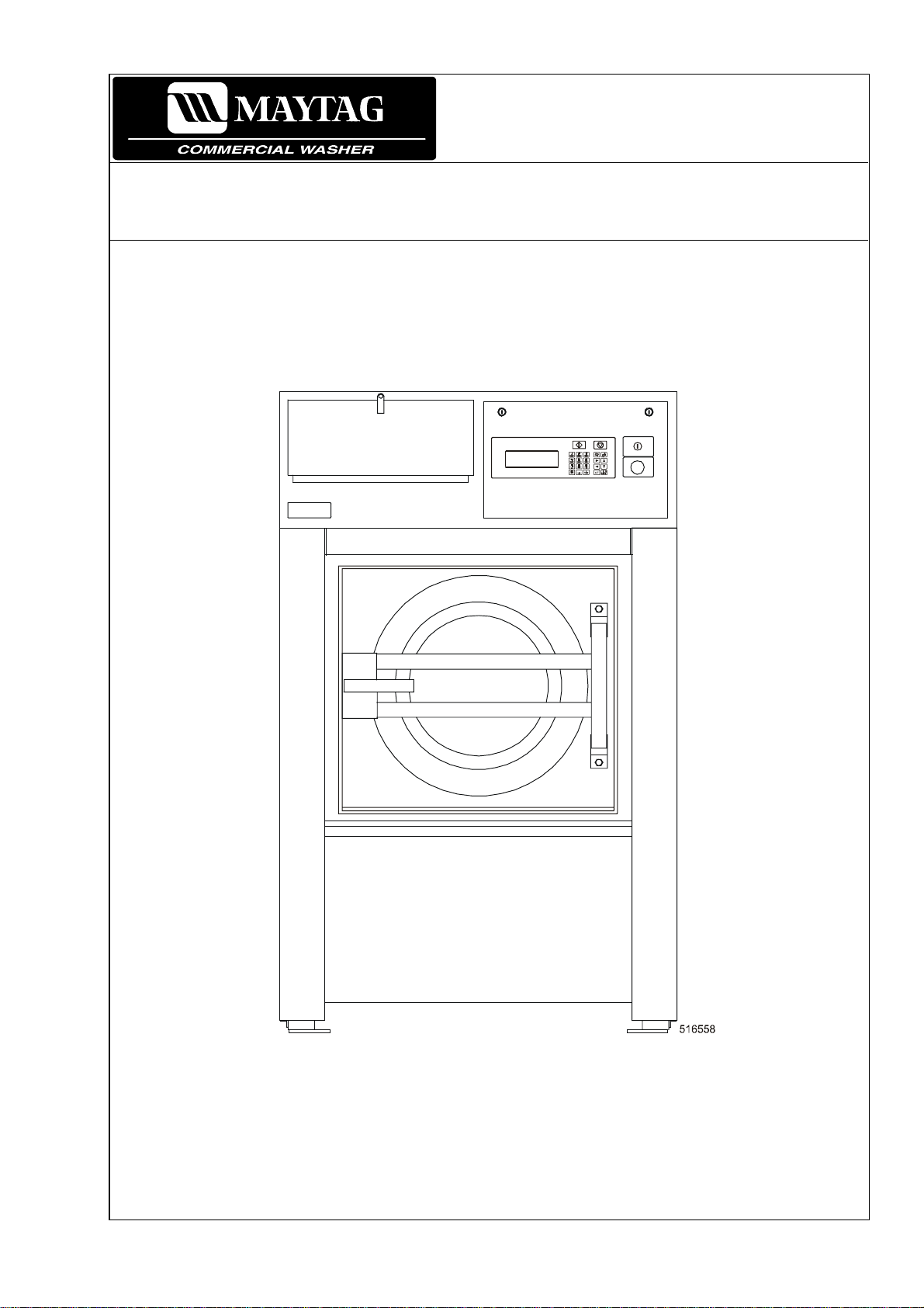
INSTALLATION AND MAINTENANCE INSTRUCTIONS INDUSTRIAL WASHERPUB DATE: 03/02 EXTRACTORS
504 766
Page 2

1. CONTENTS
Publication dat e 03/02 Page:
1. CONTENTS.....................................................................................................................1
2. WARNINGS AND SYMBOLS.........................................................................................2
2.1. PERSONAL SAFETY RULES.............................................................................................................2
2.2. SYMBOLS ON THE MACHINE...........................................................................................................2
2.3. IMPORTANT INFORMATION BEFORE INSTALLATION....................................................................3
3. TECHNICAL SPECIFICATION .......................................................................................4
3.1. MACHINES WITH 22kg / 50lbs CAPACITY.........................................................................................4
3.2. MACHINES 33kg / 80lbs CAPACITY..................................................................................................6
3.3. MACHINES 40kg / 100lbs CAPACITY ................................................................................................8
3.4. MACHINES 55kg / 125lbs CAPACITY ..............................................................................................10
3.5. DIMENSIONS AND CONNECTIONS OF THE MACHINE.................................................................12
4. INSTALLATION............................................................................................................14
4.1. HANDLING, TRANSPORT AND STORAGE.....................................................................................14
4.2. SPACE REQUIREMENTS ................................................................................................................ 15
4.3. MACHINE POSITIONING.................................................................................................................15
4.4. CONNECTIONS...............................................................................................................................17
4.5. PUTTING THE MACHINE INTO SERVICE.......................................................................................23
5. MAINTENANCE............................................................................................................24
5.1. INTRODUCTION..............................................................................................................................24
5.2. DAILY...............................................................................................................................................24
5.3. MONTHLY OR AFTER 200 WORKING HOURS...............................................................................24
5.4. EVERY 3 MONTHS OR AFTER 500 WORKING HOURS .................................................................24
5.5. EVERY 6 MONTHS OR AFTER 1000 WORKING HOURS ...............................................................24
5.6. SAFETY VIBRATION SWITCH.........................................................................................................25
5.7. TIGHTENING MOMENTS.................................................................................................................26
5.8. LUBRICATION.................................................................................................................................27
5.9. DRIVING MECHANISM....................................................................................................................28
5.10. WATER AND STEAM FILTERS......................................................................................................29
5.11. THRUST OF DOOR SEAL..............................................................................................................29
5.12. SPRING UNIT................................................................................................................................31
5.13. OVERLOAD MOTOR CURRENT PROT E CTION............................................................................31
5.14. VALUES OF FUSES.......................................................................................................................32
5.15. EARTH LEAKAGE TRIPS...............................................................................................................32
6. TROUBLE SHOOTING AIDS ........................................................................................33
6.1. DOOR BLOCKING...........................................................................................................................33
6.2. TOO LONG FILLING TIME...............................................................................................................34
6.3. TOO LONG HEATING TIME.............................................................................................................34
6.4. TOO LONG DRAINAGE TIME..........................................................................................................35
6.5. PROGRAMMER PROBLEMS...........................................................................................................35
7. LIST OF RECOMMENDED SPARE PARTS.................................................................36
8. PUTTING THE MACHINE OUT OF SERVICE..............................................................38
8.1. DISCONNECTING THE MACHINE...................................................................................................38
8.2. MACHINE LIQUIDATION..................................................................................................................38
504 766 PUBLICATION DATE 03/02 INSTALLATION AND MAINTENANCE MANUAL 1
Page 3
2. WARNINGS AND SYMBOLS
TO MINI MI ZE T HE RI SK OF FI RE, INJ URY BY EL ECT RI C SH OCK O R SERI O US I NJ URIES OF PERSO N S
OR PROPERTY DA MA GE, PL EASE REA D A ND FOLLO W THE FOLL OWING I NSTRUCTI ONS:
2.1. PERSONAL SAFETY RULES
GENERALLY
– This manual version is the translation of the original English version. Without the original version, these
instructions are incomplete. Before installation, operation and maintenance of the machine read carefully the
complete instructions supplied with the machine, i.e. this „Installation and maintenance instructions“, „User´s
manual“ and „Programming manual“ and keep the manuals in a handy place.
– Do not bypass the safety instructions stated in manuals an d warnings on the labels. Basic safety i nstructions stated
in chapters „2. WARNINGS AND SYMBOLS“ of the supplied manuals should be printed and located near the
machine for the operator's use. The labels must be readable and permanently located on the machine!
– Follow all valid local safety instructions and laws !
– Do not use the machine with its parts damaged, missing parts or opened covers !
– Do not store any flammable materials near the machine. Storing of chemical s near the ma chine or operati ng dry
cleaning machines in bad technical conditions can cause a health damage or the machine parts corrosio n.
– Do not tamper with the machine controls.
– Th e wash er mus t n ot be o perated wh en th e finger prot ection ru bbers are re moved or da maged .
– The washer extractor is intended to be permanently connected to fixed wiring.
– The machine must be connected to the power, ground, water, ventilation and steam supply according to the
installation manual, in compliance with the local standards done by qualified technicians with proper authorization.
The valid standards for connecting to the local power network (TT / TN / IT, ...) must be followed. In the standard
execution, the washer may not be suitable for connecting to an IT supply system.
– If your electrical supply has a neutral wire and this wire is not used by the machine and thus not connected to the
machine, make sure the neutral wire is properly isolated by a qualified technician.
– If you have a machine with frequency inverter do not change the parameters of the inverter. Doing so can cause
serious injury, fire, machine damage, etc.
– Instructions and warnings included in this manual do not cover all possible conditions and situations that can
occur at installation, maintenance or operations of the machine. They must be understand in common sen se.
Caution and carefulness are factors that can not be achieved by the design of machine. These factors are conditioned
by qualification and competence of personnel who install, operate and maintain the machine.
– In case of a problem or situations that you can not solve by yourselves, contact your qualified serviceman,
manufacturer or the dealer. Always state the model and serial number of your machine from the completed las t
page of the manual.
FOR MAINTENANCE
– When the main switch is off, the inlet terminals of the switch are still under current!
– Do not bypass any safety devices or their parts. Any interference to the machine function and design are
prohibited and the manufacturer does not bear any responsibilities in such cases!
– Before maintenance activities always disconnect the machine power supply!
– Do not repair or replace any machine parts and do not perform machine service work if it is not recommended in
the maintenance instructions. All other service activities should be provided by qualified service workers.
– Do not repair or adjust the machine belt drives while in operation. Turn off the main switch!
– Original or identical parts must be used for replacement in this machine. After servicing replace and secure all
panels in the original way. Take these measures for continued protection against electrical shock, injury, fire
and/or property damage.
– Once in 3 months, check the earthing and the emergency function.
– Keep the machine top clean and free of flammable materials. Do not wash or spray the machine by water.
– For the steam heated version:
In case of steam leakage, shut-off the main valve of steam supply and call the maintenance worker.
INSTALLATION AND SERVICE CAN BE DONE BY A SERVICE COMPANY WITH PROPE R
AUTHORIZATION FROM TH E M ANUFACTURER .
The machine warranty can be cancelled if the instructions of this manual are not followed.
2.2. SYMBOLS ON THE MACHINE
Danger, read and follow written instructions
Caution, high power voltage, electrical devices
Press push button in case of emergency
2 INSTALLATION AND MAINTENANCE MANUAL PUBLICATION DATE 03/02 504 766
Page 4

2.3. IMPORTANT INFORMATION BEFORE INSTALLATION
FOR TRANSPORTAT ION AND ST ORAGE
IN CASE OF TRANSPORTATION AND STORAGE, WATCH COMPONENT S PROTRUDING FROM THE
CONTOUR LINE OF MACHINE (DOOR LOCKS ETC.), TO AVOID INJURIE S.
– Never push, pull or exer t pressure on c omponents protrudi ng from the m ac hine c ontour line (controls,
door locks etc.).
– Make sure that these components are secured so as to avoid damages during m ac hine manipulation and
installation.
– In case of the machine transport ation by the customer, follow the manufacturer's instruc tions for
transportation, handling and storage of the produc t. In case of transportati on of mac hine by the customer
the manufact ur er is not r esponsible for possible damage of machine in the course of transportati on. In
case of storage the m ac hine in a free ar ea it m ust be pr otected against mechanic al dam age and weather
condition factors.
– The ambient tem per ature of transportation and storage m ust be between -25°C / -13°F to +55°C / 131°F.
Relativ e humidit y m ust be between 30% to 90% without condensation. I n c ase of stor age the machine in a
free area it must be protec ted against mechanical damage and weather c ondition factors.
FOR INSTALLATION
ELECTRICAL CONNECTION, EARTHING AND VENTING OF THE MACHINE, WATER INLETS AND
DRAINAGE MUST BE PERFORMED BY QUALIFIED PERSONNEL WITH A PROPER AUTHORIZATION
ACCORDING THE INSTALLATIO N MANUAL IN COMPLI ANCE WIT H LOCAL STANDARDS
(APPLICABLE ALSO FOR STEAM CONNECTION ON STEAM HEATED MACHINES).
– Do not install the m ac hine at places exposed to climatic eff ects or exc essive humidity. The machine is not
designed to accept env ironment with sprayed water.
– Any changes in the mac hine installations must be approved by dealer or manufacturer. Otherwise the
dealer/manufacturer is not responsible for possible injuries or damages. Interference and changes in the
machine construc tion are not allowed and the manufacturer refuses any responsibilities in such cases.
– Define dangerous areas in the laundry room and do not allow people to enter if the machine is in operation.
MACH IN E INFORM ATION
– This manual comprises information for the soft - mount m achi ne series with a load of dry linen 22, 33, 40,
55 kg (50, 80, 100 and 125 lbs). V erify the type of your machine according t o your order and the name
plate locat ed on the mac hine r ear and find corresponding inform ation in the manual.
– The machines are controlled by electronic or card pr ogr ammers. Find the programming instruc tions by a
type of programmer in the programming manual. The ver si on with an electronic programmer is either
2 - motor or 1 - motor with a frequency controlled drive.
– Machine 22 kg / 50 lbs capacity has 5 soap hoppers filled from front or 3 soap hoppers filled from top of
machine (frequency dr ive and electronic programm er only ) .
– Heating is provi ded by elec trical heating elements or by steam from y our steam system.
– Water inlets can use warm, c old sof t and possibly also cold hard water. A mac hine c an be equipped
with recycled discharging, dosing pumps for liquid soaps and machines of 22 kg/ 50 lbs capacity
with a modificati on for wet cleaning by your order.
– Electri c construc tion of the machine is 1 - phase 220 V, 3 - phase 220 V or 3 - phase 380 - 415 V (see
name plate - fig. 3.5, pos. 12).
– The machine workmanshi p whic h fulfils The European Agreement requirements is stated i n the nam e
plate by the symbol „CE“.
– All machines types are produc ed ac c or ding the EMC-directive (Electro-Magnetic-Com patibility). They can
be used in restricted surroundings only (comply minimally with class A requirements). For safety reasons
there must be kept the necessary precaution distances with sen si tive electric al or el ect r onic dev ic e( s).
– The product f ulfils the technical requirement s for a pr oduct to be assessed by the law no. 22 / 1997 Sb. of
Czech Republic.
– Models with elec tronic programmers and 5 soap hoppers, 2 - mot or and feeding voltage 3 x 208 - 240 V
(models with fr equenc y drive 3 x 208 - 230 V), 3 x 440 V and 3 x 480 V with „CSA“ mark in the name plate
are approved by the „Canadian Standards Associati on“ testing - certificate no. LR 107387-4.
504 766 PUBLICATION DATE 03/02 INSTALLATION AND MAINTENANCE MANUAL 3
Page 5
3. TECHNICAL SPECIFICATION
3.1. MACHINES WITH 22kg / 50lbs CAPACITY
1-Motor version 2-Motor version
CAPACITY:
DIMENSIONS
PACKING DIMENSIONS:
width
depth
height
transportation capacity
MACHINE DIMENSIONS:
width
depth
height
DIMENSIONS OF INNER DRUM:
diameter
depth
drum capacity
door opening
*
WEIGHT
1100 mm / 43,3“
1260 mm / 49,6“
1920 mm / 75,6“
2,66 m3 / 99,90 ft
1000 mm / 39,36“
1160 mm / 45,66“
3 soap hoppers: 1503 mm / 59, 2“
5 soap hoppers: 1640 mm / 64, 57“
750 mm / 29,5“
498 mm / 19,7“
220 dm
410 mm / 16,10“
3
/ 58 gal
22kg / 50lbs
3
WEIGHT:
Net weight
Gross weight
740 kg / 1631 lbs
830 kg / 1829 lbs
ELETRICAL DATA
Permitted deviations of feeding voltage for machines
(with and without load) :
Electri c al system of t he m ac hi ne:
TOTAL INPUT OF THE MACHINE WITH:
electric heating 18 kW
no heating
steam heating
NOMINAL OUTPUT OF THE MOTOR AT RPM:
washing / distribution
spinning low / high
INPUT PROTECTION FOR ONE MACHINE:
with elect ri c heating 18 kW (230V 3AC)
with elect ri c heating 18 kW (400V 3AC)
without elec tric heating (230V)
without elec tric heating (400V)
Overload pr otection of the motor: eletronic pr otection on
±10%, with a maximal standard deviation of the
frequency 1%
3x380-415V+N 50/60Hz
- applic abl e for el. heatin g
1x220-240V 50 /60Hz
not applicable for el. heating
-
3x220-240V 50/60Hz
applicable for el. heating
-
3x380-480V 50/60Hz
21,6 kW
3,6 kW
3,6 kW
400 V
3 kW
3 kW
63 A
32 A
20 A
20 A
the frequency invertor
tab. 3.1
677 kg / 1493 lbs
717 kg / 1581 lbs
3x380-415V 50Hz
3x380V 60Hz
3x440-480V 60Hz
3x220-240V 50Hz
3x208-240V 60Hz
380-440V
3AC:
18,9 kW
3,6 kW
3,6 kW
400 V: 0,55 / 0,65 kW
230/480V: 0,73/ 0,9 kW
400 V: 1,8 / 2,2 kW
230/480V: 2,2 / 2, 6 kW
63 A
32 A
20 A
20 A
overcurr ent relay
208-240 V /
480V:
19,1 kW
3,6 kW
3,6 kW
4 INSTALLATION AND MAINTENANCE MANUAL PUBLICATION DATE 03/02 504 766
Page 6
1-Motor version 2-Motor version
CAPACITY: 22kg / 50lbs
WASHING FUNCTION
RPM OF THE DRUM:
washing
distribution
low spinning
high spinning
G - factor of spinning max. 310 310
7 - 50 rpm
90 rpm
301 - 860 rpm
42 rpm
90 rpm
435 rpm
860 rpm
HEATING
TYPES OF HEATING:
steam
100 % electric 18 kW
100 % hot water max 90°C / 194°F
ATTACHMENT
OF WATER INLETS:
water pressure
water inlet
OF WATER DRAINAGE:
dimension
capacity
OF STEAM HEATING:
steam attachment
steam pressure
Connections to external liquid soap supply system 1 connection f or manifold
Soap hoppers: 3 / 5 5
0,3 - 0,6 MPa / 44 - 87 PSI
3/4“
∅ 76 mm / ∅ 3“
150 dm
3/4“
0,3 - 0,8 MPa / 44 - 116 PSI
(1 - 5, 6 - 10, ... connecti ons) t o liquid soap supply
system
3
/min / 40 US gal/min
CONSUMPTION
Mean water consumption: depends on selected program me cca 550 dm3 /
145 US gal
STEAM CONSUMPTION:
depends on selected program me
Maximum steam consum ption
22 kg. cycle
0,024 kg.s-1 (88 kg.h-1) / 0,054 lbs.s-1 (194 lbs.h-1)
-1
/ 48,51 lbs. cycle
-1
WORKING CONDITIONS
ambient temperature
mean ambient temper ature in 24 hrs
relative humidity
height abov e sea level
from +5°C / 41°F to +40°C / 104°F
to +35°C / 95°F
30% ÷ 95% without condensation
to 1000 m
ANCHORING
Bolt: 4 pcs M10
max. static loading (with linen and water)
max. dynamic loading
(alternative stress when extracting)
frequency of dy nami c loading
831kg / 1833lbs
± 140 kg / ± 309lbs
14,5 Hz
NOISE
Mean noise level at max. l oading: 70,6 dB (A)
maximum dimensions includi ng pr otr uding parts
*
504 766 PUBLICATION DATE 03/02 INSTALLATION AND MAINTENANCE MANUAL 5
tab. 3.1 continuation
Page 7

3.2. MACHINES 33kg / 80lbs CAPACITY
CAPACITY:
DIMENSIONS
PACKING DIMENSIONS:
width
depth
height
transportation capacity
MACHINE DIMENSIONS:
width
depth
height
DIMENSIONS OF INNER DRUM:
diameter
depth
drum capacity
door opening
WEIGHT:
netto
brutto
*
WEIGHT
1-Motor version 2-Motor version
33kg / 75lbs
1430 mm / 56,3“
1475 mm / 58,1“
2105 mm / 82,87“
3
4,4 m
1195 mm / 47,04“
1330 mm / 52,4“
1905 mm / 75“
914 mm/ 36“
510 mm / 20“
335 dm
540 mm / 21,3“
1230 kg / 2712 lbs
1370 kg / 3020 lbs
/ 156 ft
3
3
/ 88 gal
1366 kg / 3012 lbs
1466 kg / 3233 lbs
ELETRICAL DATA
Permitted dev iations of feeding voltage for
machines:
Electri c al system of t he m achine: 3x380-480V 50/60Hz
TOTAL INPUT OF THE MACHINE WITH:
electric heating 24 kW
no heating
steam heating
NOMINAL OUTPUT OF THE MOTOR AT RPM:
washing / distribution
spinning low / high
INPUT PROTECTION FOR ONE MACHINE:
with elect ri c heating 24 kW (230 V)
with elect ri c heating 24 kW (400 V)
without elec tric heating (400V / 50 Hz, 480V / 60 Hz)
without elec tric heating (230 V)
Overload pr otection of the motor:
±10%, with a maxim al standard deviation of the
frequency 1%
3x200-240V 50/60Hz
28,8 kW
4,8 kW
4,8 kW
4 kW
4 kW
80 A
50 A
20 A
30 A
eletronic pr otection on
the frequency invertor
3x380-415V 50Hz
3x380V 60Hz
3x440-480V 60Hz
3x220-240V 50Hz
3x208-240V 60Hz
380-440V
3AC:
24,9 kW
3,6 kW
3,6 kW
400 V: 0,55 / 0,65 kW
230/480V: 0,65/ 0,75kW
400 V: 1,8 / 2,2 kW
230/480V: 2,2 / 2, 6 kW
80 A
50 A
20 A
20 A
overcurr ent relay
208-240 V /
480V:
25,1 kW
3,6 kW
3,6 kW
tab. 3.2
6 INSTALLATION AND MAINTENANCE MANUAL PUBLICATION DATE 03/02 504 766
Page 8

1-Motor version 2-Motor version
CAPACITY: 33kg / 75lbs
WASHING FUNCTION
RPM OF THE DRUM:
washing
distribution
low spinning
high spinning
G - factor of spinning max. 365 365
7 - 50 rpm
90 rpm
301 - 830 rpm
36 rpm
59 rpm
435 rpm
845 rpm
HEATING
Types of heati ng: steam
100 % electric 24 kW
100 % hot water max 90°C / 194°F
ATTACHMENT
OF WATER INLETS:
water pressure
water inlet
OF WATER DRAINAGE:
dimension
capacity
OF STEAM HEATING:
steam attachment
steam pressure
COMPRESSED AIR:
air connecti on
air pressure
Connections to external liquid soap supply system 1 connection for manifold
Soap hoppers: 5
*
*
0,3 - 0,6 MPa / 44 - 87 PSI
1“
2 x ∅76 mm / 2 x ∅ 3“
300 dm
3/4“
0,3 - 0,8 MPa / 44 - 116 PSI
G 1/4“
0,3 - 0,8 MPa / 44 - 116 PSI
(1 - 5, 6 - 10, ... co nne ctions) to liquid soap supp ly
system
3
/min / 80 US gal/min
CONSUMPTION
Mean water consumption: depends on selected program me cca 900 dm3 /
240 US gal
STEAM CONSUMPTION:
depends on selected program me
Maximum steam consum ption
33 kg. cycle
0,046 kg.s-1 (165 kg.h-1) / 0,101 lbs.s-1 (364 lbs.h-1)
-1
/ 72,77 lbs. cycle
-1
WORKING CONDITIONS
ambient temperature
mean ambient temper ature in 24 hrs
relative humidity
height abov e sea level
from +5°C / 41°F to +40°C / 104°F
to +35°C / 95°F
30% ÷ 95% without condensation
to 1000 m
ANCHORING
Bolt: 4 pcs M16
max. static loading (with linen and water)
max. dynamic loading
(alternative stress when extracting)
frequency of dy nami c loading
1597kg / 3521lbs
± 280kg / ± 618lbs
14 Hz
NOISE
Equivalent noise level at spinning cycle L
Level of acoustic output L
maximum dimensions includi ng pr otr uding parts
*
it is valid for machines, which have water valves with air oper ated control
*
*
: 84,7 dB (P,A)
P,A
: 80,8 dBA
Aeq
tab. 3.2 continuation
504 766 PUBLICATION DATE 03/02 INSTALLATION AND MAINTENANCE MANUAL 7
Page 9

3.3. MACHINES 40kg / 100lbs CAPACITY
CAPACITY:
DIMENSIONS
PACKING DIMENSIONS:
width
depth
height
transportation capacity
MACHINE DIMENSIONS:
width
depth
height
DIMENSIONS OF INNER DRUM:
diameter
depth
drum capacity
door opening
WEIGHT:
netto
brutto
*
WEIGHT
1430 mm / 56,3“
1570 mm / 61,8“
2105 mm / 82,87“
4,7 m
1195 mm / 47,04“
1430 mm / 56,3“
1905 mm / 75“
914 mm/ 36“
610 mm / 24“
400 dm
540 mm / 21,3“
1560 kg / 3439 lbs
1700 kg / 3748 lbs
1-Motor version 2-Motor version
40kg / 95lbs
3
/ 166 ft
3
3
/ 106 gal
1560 kg / 3440 lbs
1666 kg / 3674 lbs
ELETRICAL DATA
Permitted dev iations of feeding voltage for
machines:
Electri c al system of t he m achine: 3x380-480V 50/60Hz
TOTAL INPUT OF THE MACHINE WITH:
electric heating 36 kW
no heating
steam heating
NOMINAL OUTPUT OF THE MOTOR AT RPM:
washing / distribution
spinning low / high
INPUT PROTECTION FOR ONE MACHINE:
with elect ri c heating 36 kW (3x230 V)
with elect ri c heating 36 kW (3x400 V)
without electric heating (3x400V/50Hz, 3x480V/60Hz)
without elec tric heating (3x230 V)
Overload pr otection of the motor:
±10%, with a maxim al standard deviation of the
frequency 1%
3x200-240V 50/60Hz
44,7 kW
8,7 kW
8,7 kW
7,5 kW
7,5 kW
120 A
80 A
30 A
40 A
eletronic pr otection on
the frequency invertor
3x380-415V 50Hz
3x380V 60Hz
3x440-480V 60Hz
3x220-240V 50Hz
3x208-240V 60Hz
380-440V
3AC:
37,4 kW
7,3 kW
7,3 kW
400 V: 0,9 / 1 kW
230/480V: 1 / 1,1 kW
400 V: 4 / 5,2 kW
230/480V: 4,5 / 5, 8 kW
120 A
63 A
25 A
30 A
overcurr ent relay
208-240 V /
480V:
37,5 kW
7,3 kW
7,3 kW
tab. 3.3
8 INSTALLATION AND MAINTENANCE MANUAL PUBLICATION DATE 03/02 504 766
Page 10
1-Motor version 2-Motor version
CAPACITY: 40kg / 95lbs
WASHING FUNCTION
RPM OF THE DRUM:
washing
distribution
low spinning
high spinning
G - factor of spinning max. 351 351,00
7 - 50 rpm
90 rpm
301 - 830 rpm
40 rpm
64 rpm
430 rpm
830 rpm
HEATING
Types of heati ng: steam
100 % electric 36 kW
100 % hot water 90°C / 194°F
ATTACHMENT
OF WATER INLETS:
water pressure
water inlet
OF WATER DRAINAGE:
dimension
capacity
OF STEAM HEATING:
steam attachment
steam pressure
COMPRESSED AIR:
*
air connecti on
air pressure
Connections to external liquid soap supply system 1 connection for manifold
Soap hoppers: 5
*
0,3 - 0,6 MPa / 44 - 87 PSI
1“
2 x ∅76 mm / 2 x ∅ 3“
300 dm
3/4“
0,3 - 0,8 MPa / 44 - 116 PSI
G 1/4“
0,3 - 0,8 MPa / 44 - 116 PSI
(1 - 5, 6 - 10, ... connections) to liquid soap supply
system
3
/min / 80 US gal/min
CONSUMPTION
Mean water consumption: depends on selected program me cca 1195
STEAM CONSUMPTION:
depends on selected program me
Maximum steam consum ption
3
dm
/ 315 US gal
-1
40 kg. cycle
0,055 kg.s-1 (200 kg.h-1) / 0,123 lbs.s-1 (441 lbs.h-1)
/ 88,2 lbs. cycle
-1
WORKING CONDITIONS
ambient temperature
mean ambient temper ature in 24 hrs
relative humidity
height abov e sea level
from +5°C / 41°F to +40°C / 104°F
to +35°C / 95°F
30% ÷ 95% without condensation
to 1000 m
ANCHORING
Bolt: 4 pcs M16
max. static loading (with linen and water)
max. dynamic loading
(alternative stress when extracting)
frequency of dy nami c loading
Noise
Equivalent noise level at spinning cycle L
Level of acoustic output L
maximum dimensions includi ng pr otr uding parts
*
it is valid for machines, which have water valves with air oper ated control
*
*
: 86,8 dB (P,A)
P,A
: 77,0 dBA
Aeq
tab. 3.3 continuation
1746kg / 3850lbs
± 300kg / 662lbs
14 Hz
504 766 PUBLICATION DATE 03/02 INSTALLATION AND MAINTENANCE MANUAL 9
Page 11

3.4. MACHINES 55kg / 125lbs CAPACITY
CAPACITY:
DIMENSIONS
PACKING DIMENSIONS:
width
depth
height
transportation capacity
MACHINE DIMENSIONS:
width
depth
height
DIMENSIONS OF INNER DRUM:
diameter
depth
drum capacity
door opening
WEIGHT:
netto
brutto
*
WEIGHT
1-Motor version 2-Motor version
55kg / 125lbs
1430 mm / 56,3“
1750 mm / 68,9“
2105 mm / 82,87“
3
5,3 m
1195 mm / 47,04“
1610 mm / 63,4“
1905 mm / 75“
914 mm/ 36“
790 mm / 31,1“
518 dm
540 mm / 21,3“
1630 kg / 3594 lbs
1770 kg / 3902 lbs
/ 187 ft
3
3
/ 137 gal
1626 kg / 3585 lbs
1766 kg / 3894 lbs
ELETRICAL DATA
Permitted deviations of feeding voltage for machines: ±10%, with a maximal standard deviation of the
frequency 1%
Elec tr ical system of t he mac hine: 3x380-480V 50/60Hz
3x200-240V 50/60Hz
TOTAL INPUT OF THE MACHINE WITH:
electric heating 54 kW
no heating
steam heating
NOMINAL OUTPUT OF THE MOTOR AT RPM:
washing / distribution
spinning low / high
INPUT PROTECTION FOR ONE MACHINE:
with electric heating 54 kW (3x230V/60Hz)
with electric heating 54 kW (3x400V/50Hz)
without electric heating (3x400V/ 50 Hz, 3x480 V/ 60 Hz)
with steam heati ng ( 3x 230 V/60 Hz )
without elec tric heating (3x230 V / 60 Hz)
with steam heati ng ( 3x 400 V/50 Hz )
Overload pr otection of the motor: eletronic protecti on
tab. 3.4
62,7 kW
8,7 kW
8,7 kW
7,5 kW
7,5 kW
160 A
100 A
32 A
40 A
40 A
32 A
on the frequency
invertor
3x380-415V 50Hz
3x380V 60Hz
3x440-480V 60Hz
3x220-240V 50Hz
3x208-240V 60Hz
380-440V
3AC:
55,8 kW
8,2 kW
8,2 kW
400 V: 1,2 / 1,1 kW
230/480V: 1,4/ 1,2kW
400 V: 5,8 / 4,5 kW
230V: 6,5 / 5 kW
480V: 6,5 / 5,5 kW
160 A
100 A
25 A
30 A
30 A
25 A
overcurr ent relay
208-240 V /
480V:
56 kW
8,2 kW
8,2 kW
10 INSTALLATION AND MAINTENANCE MANUAL PUBLICATION DATE 03/02 504 766
Page 12
1-Motor version 2-Motor version
***
CAPACITY: 55kg / 125lbs
WASHING FUNCTION
RPM OF THE DRUM:
washing
distribution
low spinning
high spinning
G - factor of spinning max. 351 351
7 - 50 rpm
90 rpm
301 - 830 rpm
40 rpm
64 rpm
430 rpm
830 rpm
HEATING
Types of heati ng: steam
100 % electric 54 kW
100 % hot water 90°C / 194°F
ATTACHMENT
OF WATER INLETS:
water pressure
water inlet
OF WATER DRAINAGE:
dimension
capacity
OF STEAM HEATING:
steam attachment
steam pressure
COMPRESSED AIR:
air connecti on
air pressure
Connections to external liquid soap supply system 1 connection for manifold
Soap hoppers: 5
0,3 - 0,6 MPa / 44 - 87 PSI
1“
2 x ∅76 mm / 2 x ∅ 3“
300 dm
3/4“
0,3 - 0,8 MPa / 44 - 116 PSI
G 1/4“
0,3 - 0,8 MPa / 44 - 116 PSI
(1 - 5, 6 - 10, ... co nne ctions) to liquid soap supp ly
system
3
/min / 80 US gal/min
CONSUMPTION
Mean water consumption: depends on selected program me cca 1500 dm
/ 400 US gal
STEAM CONSUMPTION:
depends on selected program me
Maximum steam consum ption
Working condi tions
ambient temperature
mean ambient temper ature in 24 hrs
relative humidity
height abov e sea level
55 kg. cycle
0,076 kg.s-1 (275 kg.h-1) / 0,168 lbs.s-1 (606 lbs.h-1)
from +5°C / 41°F to +40°C / 104°F
to +35°C / 95°F
30% ÷ 95% without condensation
to 1000 m
-1
/ 121,3 lbs. cycle
-1
ANCHORING
Bolt: 4 pcs M16
max. static loading (with linen and water)
max. dynamic loading
(alternative stress when extracting)
frequency of dy nami c loading
1951kg / 4302lbs
± 320kg / 706lbs
14 Hz
NOISE
Equivalent noise level at spinning cycle L
Level of acoustic output L
maximum dimensions includi ng pr otr uding parts
*
it is valid for machines, which have water valves with air oper ated control
: 86,8 dB (P,A)
P,A
*
: 77,0 dBA
Aeq
tab. 3.4 continuation
3
504 766 PUBLICATION DATE 03/02 INSTALLATION AND MAINTENANCE MANUAL 11
Page 13

3.5. DIMENSIONS AND CONNECTIONS OF THE MACHINE
33/40/55 kg 80/100/125 lbs 22 kg / 50 lbs - „5 soaphoppers“
22 kg / 50 lbs - „3 soaphoppers“
Fig. 3.5.
12 INSTALLATION AND MAINTENANCE MANUAL PUBLICATION DATE 03/02 504 766
Page 14

1. Front panel with operating elements
2. Electric switchboard cover
3. Tub ventilation
4. Lubrication
5. Bushing of external dosing pumps el ectric connection
6. Main power supply bushi ng
7. Main swit c h
8. Hard cold wat er inl et
9. Hot water inlet
10. Soft cold water inlet
11. Plug of hole for ext ernal dosing hose
12. Name plate
13. Steam inlet
14. External protective clamp
15. Draining outlet
16. Soap hopper ventilation
17. Frequency invertor cover
18. Compressed air supply
19. Soap hoppers
Machine
capacity:
A
A1
*
B
22 kg/ 50 lbs
3 soap hoppers
985 mm
38,78“
--
1503 mm
59,2“
22 kg/ 50 lbs
5 soap hoppers
1000 mm
39,36“
1640 mm
64,57“
B1 --
*
*
C
D
E
F
G
H
I
J
K
L
M
N
O
P
P
Q
R
S
T
U
V
W
X
Y
Z
867 mm
34,13“
1025 mm
40,35“
917 mm
36,1“
1233 mm
48,54“
401 mm
15,8“
1417 mm
55,8“
317 mm
12,5“
235 mm
9,25“
80 mm
3,15“
124 mm
4,9“
1382 mm
54,41“
130 mm
5,1“
1272 mm
50,1“
591 mm
23,27“
176 mm
6,93“
200 mm
7,87“
282 mm
11,08“
130 mm
5,14“
77 mm
3,03“
530 mm
20,87“
867 mm
34,13“
1160 mm
45,66“
917 mm
36,1“
-
-
-
--
--
25 mm
1“
45 mm
1,77“
two motors: 1437 mm /
56,57“
one motor: 1233 mm / 48,54“
173 mm
6,79“
two motors: 87 mm / 3,43“
one motor: 168 mm / 6,61“
1388 mm
54,63“
362 mm
14,25“
-
160 mm
6,3“
104 mm
4,09“
1522 mm
59,9“
130 mm
5,1“
1264 mm
49,76“
591 mm
23,3“
176 mm
6,93“
200 mm
7,87“
282 mm
11,08“
130 mm
5,14“
77 mm
3,03“
530 mm
20,87“
33 kg
80 lbs
1195 mm
47,04“
1361 mm
53,58“
1905 mm
75“
116 mm
4,56“
1055 mm
41,54“
1330 mm
52,4“
1222 mm
48,11“
300 mm
11,8“
50 mm
1,97“
1617 mm
63,66“
---
730 mm
28,74“
1567 mm
61,69“
422 mm
16,61“
80 mm
3,15“
80 mm
3,15“
70 mm
2,75“
1782 mm
70,16“
1672 mm
65,82“
160 mm
6,3“
1565 mm
61,6“
65 mm
2,56“
768 mm
30,24“
205 mm
8,07“
213 mm
8,39“
420 mm
16,54“
175 mm
6,89“
195 mm
7,68“
700 mm
27,56“
40 kg
100 lbs
1195 mm
47,04“
1361 mm
53,58“
1905 mm
75“
116 mm
4,56“
1055 mm
41,54“
1430 mm
56,3“
1322 mm
52,05“
300 mm
11,8“
50 mm
1,97“
1617 mm
63,66“
730 mm
28,74“
1567 mm
61,69“
422 mm
16,61“
80 mm
3,15“
80 mm
3,15“
70 mm
2,75“
1782 mm
70,16“
1672 mm
65,82“
160 mm
6,3“
1565 mm
61,6“
65 mm
2,56“
768 mm
30,24“
205 mm
8,07“
213 mm
8,39“
275 mm
10,83“
175 mm
6,89“
195 mm
7,68“
700 mm
27,56“
55 kg
125 lbs
1195 mm
47,04“
1361 mm
53,58“
1905 mm
75“
116 mm
4,56“
1055 mm
41,54“
1610 mm
63,39“
1502 mm
59,13“
300 mm
11,8“
50 mm
1,97“
1617 mm
63,66“
730 mm
28,74“
1567 mm
61,69“
422 mm
16,61“
80 mm
3,15“
80 mm
3,15“
70 mm
2,75“
1782 mm
70,16“
1672 mm
65,82“
160 mm
6,3“
1565 mm
61,6“
65 mm
2,56“
768 mm
30,24“
205 mm
8,07“
213 mm
8,39“
275 mm
10,83“
175 mm
6,89“
195 mm
7,68“
700 mm
27,56“
– it is valid for machines, which have water valves with air operat ed c ontrol
*
504 766 PUBLICATION DATE 03/02 INSTALLATION AND MAINTENANCE MANUAL 13
Page 15

4. INSTALLATION
4.1. HANDLING, TRANSPORT AND STORAGE
TRANSPORT AND ST ORAGE
WARNING !
!
FORKS OF HIGH LIFTING TRUCK MUST HAVE SUFF ICIENT LENGTH (SEE FIG. 4.1.A).
Use a lift truck or a manual ski d c art for handling with the machine in transport ing package.
– The ambient tem perature of transportat ion and stora ge must be betwe en -25° C / -13°F and +55°C / 131°F .
The machine may not be instal led within the reach of spraying water. Avoid severe climatic conditions and
excessiv e humi dity. When steamed up due to the temperatur e to the tem per ature changes, water must
not run over the walls and covers of the machine nor to cover the floor under and around it.
– If possible, leav e the mac hine in the transporting package or at least let it set on the transporting wooden
skid until the time of final installation on the foundat ion according the chapter 4.3. of this manual.
22 kg 33/40/55 kg
1100 mm 1500 mm
50 lbs 80/100/125 lbs
44“ 59“
Fig. 4.1 A Minimum length „X“ of lift truck forks for individual machine types including package
HANDLING DURING INSTALLATION
All activ ities can be done only by a worker, which knows all inf ormati on about the machine. Machine is
delivered to t he customer in a wooden packing and protected wit h poly ethylene film. The machine is
attached to the ski d by means of f our bolts M16 (for machine 22 kg / 50 lbs capacity: M12).
To remove the machine to its final location follow these precautions:
– All passages and spaces the machine has to be transported through at installation should be reasonabl y
dimensioned to m eet t he height and width of the machine includi ng the pac k age.
– Never push, pu ll or press th e compo nents protruding from the contour line of machine (front part,
filling door, cont rol elements, belt cover, water inlet and outlet pipes etc.).
MAKE SURE THAT THESE COMPONENTS ARE SECURED SO AS TO AVOID THEIR DAMAGE
DURING HANDLING AND INSTALLATION OF THE MACHINE.
– Make sure th at th e fill ing doo r are secured to avoid its opening during the handli ng .
– Lift the machi ne up by lift t r uc k using a transport skid to which the machine has been at tached.
UNPACKING
After unpacki ng, check if the machine has not been damaged and if all the ac c essories are included
according t o your order . Verify the type of your machine by a name plat e loc ated on t he machine rear and
find corresponding information in the manual . T he accessories and the manual is locat ed insi de of the drum,
which can be opened accordi ng to chapter 6.1.
Before the mac hine loc ating to its place, remove the packaging, loosen four nuts and lift the machine
carefully up - t ak e care not to dam age the machine components located in it s lower part. The lift truck forks
must be at least 10 cm longer t han the lengt h of the washing machine frame (tab. 4.1. ).
22 kg 33 kg 40 kg 55 kg
1100 mm 1222 mm 1322 mm 1502 mm
50 lbs 80 lbs 100 lbs 125 lbs
44“ 48“ 52“ 59“
Tab. 4.1. Minimum length „X“ of a lift truck forks for indiv idual m ac hi ne types without packing
14 INSTALLATION AND MAINTENANCE MANUAL PUBLICATION DATE 03/02 504 766
Page 16

4.2. SPA CE REQUIREMENT S
REQUIRED MACHINE WORKING CONDITIONS:
See chapter „3. TE CHNICAL S PECI FI CATIO N“ .
The machine may not be instal led within the reach of directly spraying water. Do not install the m achi ne
where it will be exposed to weather c ondition and excessiv e humi dity. When steamed up due to
temperature c hanging, water must not run over the machine walls and covers, nor to cover the floor under
and around it.
SIZE OF A LAUNDRY ROOM
IGNORING THE REQUIREMENT FOR SPACES BETWEEN MACHINES AND WALLS CAN MAKE
SERVICE AND MAINTENANCE WORK DIFFICULT.
Total space requir em ents for the system installati on ar e usual ly determinate by a detailed plan of the
building. The machine dimensions are stated in the chapter „3. TECHNICAL SPECIFICATION“.
Leave at least 1 m / 3 ,3 ft o f a space between the mach ine rear and the wall for th e maintenance ac cess .
Between the lateral sides of each machine leave a minimum space of 0,7 m / 2,3 ft (see fig. 4.3. A, dimension
„I“). Above the machine must be minimu m 0,7 m / 2,3 ft o f fr ee spac e fo r the mainte na nce access .
The waste piping or outl et channel must be dimensioned to the di scharged water quantity and a number of
washing machines.
4.3. MACHINE POSITIONING
CARRYING CAPACITY OF THE FLOOR
WARNING !
!
IT IS RECOMMENDED TO CONSULT STATIC REQUIREMENTS WITH A STATIC A ENGINEER TO
MEET THE REQUIREMENTS OF PERMISSIBLE LOADING, VIBRATIONS AND A NOISE LEVEL IN
THE BUILDING.
THE MANUFACTURER DOES NOT RECOMMEND TO INSTALL THE WASHING MACHINE IN A
ROOM WITH A CELLAR OR ON A FLOOR HAVING ROOMS BENEATH.
!
WARNING !
IN CASE OF INSTALLATION IN A ROOM WITH A CELLAR OR ON A FLOOR HAVING ROOMS
BENEATH:
THE INST ALLATION MUST BE APPROVED BY A STATIC ENGINEER TO MEET THE
REQUIREMENTS OF PERMISSIBLE LOADING, VIBRATIONS AND A NOISE LEVEL IN THE
BUILDING. THE MANUFACTURER IS NOT RESPONSIBLE FOR SUCH EFFECTS.
MODEL
Maximum static load of the floor
(with linen and water)
Maximum dinamic load of the floor
(alternative stress when extracting)
Dynamic load frequency of the floor Hz 14,50 14,00 14,00 14,00
kg
lbs
kg
lbs
Tab. 4.3. A
22 kg
50 lbs
831
1832
±140
±309
33 kg
80 lbs
1597
3521
±280
±617
40 kg
100 lbs
1746
3850
±300
±662
55 kg
125 lbs
1951
4302
±320
±706
FASTENING THE MACHINE
THE MACHINE WILL BE FIRMLY FIXED TO THE FLOOR AND MUST RELIABLY REST IN ALL FOUR
FOOTI N GS OF THE MACHIN E !
The machine is to be loc ated on a levelled concrete floor to comply with static and dynamic stress of the
machine. Chec k the posi tion of the machine base frame by a water level. T he m anufacturer is not
responsible f or c onsequences caused by a wrong installation. It is expected to use anchoring bolts for fixing
the machine to the floor . There is also possible to use a suitable outlet channel for the waste water
(fig.4.3.A), unless the machine is connect ed to a dr ain pipeline.
WARNING !
!
THE NUTS OF THE ANCHORING BOLTS HAVE TO BE TIGHTENED BY MEANS OF A TORQUE LIMITING RANGE (SEE TAB. 4.3.B). DO NOT TIGHTEN NUTS OF ANCHORING BOLTS BEFORE THE
CONCRETE BASE AROUND THE BOLTS IS COMPLETE LY CURE D. FOR CS A-NRTL/ C APPRO V E D
MACHINES FOLLOWING IS APPLICABLE: TO RE DUCE THE RISK OF FIRE, THIS APPLIANCE
MUST BE BOLTED TO AN UNCOVERED CONCRETE FLOOR.
504 766 PUBLICATION DATE 03/02 INSTALLATION AND MAINTENANCE MANUAL 15
Page 17

22 kg / 50 lbs 33 kg / 80 lbs 40 kg /100 lbs 55 kg / 125 lbs
BOLT
TIGHTENING MOMENT
M10 x 160 mm M16 x 160 mm
49 Nm / 36 lbf.ft 210 Nm / 155 lbf.ft
Tab.4.3.B
Fig.4.3. A Di stanc es between washi ng machines, walls and between other machines
and optional design of the waste channel
1. Machine line of contour
2. Machine footing
3. Waste sump
4. Anchoring bolt
5. Draini ng elbow
6. Cover of waste sump
16 INSTALLATION AND MAINTENANCE MANUAL PUBLICATION DATE 03/02 504 766
Page 18

X
1
X
2
X
3
X
4
X
5
X
6
X
7
X
8
X
9
22 kg
50 lbs
774 mm
30,47“
886 mm
34,88“
1066 mm
42“
750 mm
29,5“
50 mm
1,95“
75 mm
2,97“
40 mm
1,6“
150 mm
6“
196 mm
8“
33 kg
80 lbs
970 mm
38,19“
930 mm
36,61“
1175 mm
46¼“
830 mm
32,7“
130 mm
5,12“
77mm
3,03“
60 mm
2,36“
160 mm
6,3“
350 mm
14“
40 kg
100 lbs
1070mm
42,13“
930 mm
36,61“
1175mm
46¼“
830 mm
32,7“
130 mm
5,12“
77mm
3,03“
60 mm
2,36“
160 mm
6,3“
350 mm
14“
55 kg
125 lbs
1250 mm
49,21“
930 mm
36,61“
1175 mm
46¼“
830 mm
32,7“
130 mm
5,12“
77mm
3,03“
60 mm
2,36“
160 mm
6,3“
350 mm
14“
X1
X1
X1
X1
X1
X1
X1
X1
22 kg
50 lbs
200 mm8“ 300 mm
0
250 mm9“250 mm
1
100 mm4“200 mm
2
232 mm
9,15“
3
300 mm
12“
4
100 mm4“150 mm
5
150 mm6“180 mm
6
180 mm7“200 mm
7
*) hole optimaliz ed for new floor, drilled hole can be smallish dimension
Tab.4.3.C
4.4. CONNECTIONS
33 kg
80 lbs
12“
9“
8“
250 mm
9“
750 mm
29½“
6“
7“
8“
40 kg
100 lbs
300 mm
12“
250 mm9“250 mm
200 mm8“200 mm
250 mm9“250 mm
750 mm
29½“
150 mm6“150 mm
180 mm7“180 mm
200 mm8“200 mm
55 kg
125 lbs
300 mm
12“
9“
8“
9“
750 mm
29½“
6“
7“
8“
CONNECTION OF WATER SUPPLIES
WATER HARDNESS
It is advisable to contact the water supplier for information concerning the properties of the water in your
area. Good wash results are dependent also on the water hardness. F or m edium to ver y hard water,
considerati on shoul d be m ade to make the water softer.
Only in some cases is the use of hard water desi r able, such as adding softener in the linen.
The soap supplier c an help y ou with maki ng the right decisions concerning hard water, soft water, washing
programs, t y pe of soap and other r elated items to have the best wash results.
Characteristics mmol / dm
3
dH -
Germany
soft 0 - 1,25 0 - 7° 0 - 12° 0 - 8,75° 0 - 3
medium 1,25 - 2,5 7 - 14° 12 - 25° 8,75 - 17,5° 3 - 7
hard 2,5 - 3,75 14 - 21° 25 - 37° 17,5 - 26,3° 7 - 15
very hard above 3,75 abov e 21° above 37° above 26,3° above 15
Tab.4.4.A
HOT WATER
When the machine is provided with a hot water inlet, we advise connect ing this inlet to a hot water supply
that is set to 70°C / 158°F. The hot water supply needs to be large enough to provi de the requi r ed hot
water for the washers.
fH -
France
England
gr/gal
USA
WATER CONNECTION
Most machines are made wit h 2 or 3 water inlets. One is always marked with „soft water“. If more inlets are
present, they are m ar k ed with „Hot water“ or „Hard water“. For connection dimensions see fig. 3.5. Al ways
use the flexible hose delivered with the machine, if not pr esent , contact your dealer. In each case do not
use a fixed connecti on to the water supply.
For the proper function of the machine, it is necessary to keep t he water pr essure within the limits stated in
the technical data. It is also necessary to connect all av ailable water inlets to a water supply. If a hard water
supply is not present, c onnec t it with soft water. If no hot water supply is present, contact your dealer for the
proper required ac tion.
504 766 PUBLICATION DATE 03/02 INSTALLATION AND MAINTENANCE MANUAL 17
Page 19

Inlet valves 1“ (machine 22 kg / 50 lbs capacity: 3/4“) for cold and hot water are delivered with the mac hine.
For these valv es use inlet pressure hoses with gaskets. Mount shut - off v alv es 1“ (m ac hine 22 k g / 50 lbs
capacity: 3/4“) to the water supply pipes, it will mak e the maintenanc e and cl eaning of filters delivered with
a machine easy.
For connection of t he m ac hine to water inlet shut-off val ves we recommend to use enclosed flexible hoses
(960mm / 38“ long) with couplings 1“ (machine 22 kg / 50 lbs capacit y.: 3/ 4“ ).
If you connect t he water inlet without using flexibl e hoses, i nstall connections to the connec ting points; this
will make possible to dismantle valves / filters i n case of f ailure.
WATER DRAIN CONNECTION
The washer is equipped with 2 dr ain pipes (machine 22 kg / 50 lbs : only 1) of 75 mm (3“) diameter, located
in the machine rear wall. These must be connected to the waste sump.
The waste sump must be locat ed lower than the drain pipes because the water discharges from the
machines by gravit y . Do not reduce t he diam eter of the machine drain pipes.
To connect the machine dr ainage to a waste sump, you can use the elbow 75 mm /3“ which is a part of the
delivery. Secur e the elbow with a clamp. Cover the waste sump with a proper c ov er .
22 kg / 50 lbs 33 kg / 80 lbs 40 kg / 100 lbs 55 kg/125 lbs
dm3 /min
US galons / min
150,00 300,00 300,00 300,00
40,00 80,00 80,00 80,00
Tab. 4.4.B Capacity of discharged water
STEAM CONNECTION
The washing machi ne with a steam heating is equipped with an outer t hr ead G 3/ 4“ in the mac hine rear part
for connecting to the laundry steam line. For dimensions of connection points see fig. 3.5. The value of inlet
steam pressure must cor r espond to the range stated in chapter „2. Technical specificati on“ . Any other
pressure val ues can cause an improper or insufficient function of the machine.
WARNING !
!
STOP THE MAIN STEAM INLET AND LET THE PARTS COOL DOWN AFTER THE CONNECTION TO
AVOID POSSIBLE INJURIES.
WARNING !
!
BEFORE EVERY ST EAM VALVE IT IS NECESSARY TO INSERT THE FILTER WITH PERMEABILITY
UP TO 300 MICROMETERS. POSSIBLE DIRT BIGGE R THAN 300 MICROMETERS MIGHT DAMAGE
THE STEAM VAL VE AND CAUSE ITS LEAKAGE.
Attach the steam fil ter which is a part of the delivery to the machine c onnec ting point. The supply pipi ng
must be clean without dirt particles and rust residues. Impurities in supply line may cause failures of steam
valves.
WHEN CONNECTING THE PIPES DO NOT TWIST THE FILTER GASKET. THE ASSEMBLY SHUT BE
MADE BY CLAMPING THE FILTER AT THE SIDE OF CONNECTING PIPE.
To enable a possible dismantling of the steam valve, equipped the attaching point with a connector.
VENTING
WARNING !
!
WATCH FOR A STEAM ESCAPE FROM THE MACHINE VENTING (FIG. 3.5, POS. 3 AND 16),
DANGER !
DO NOT COVER THE MACHINE VENTING; IT SERVES AS A STEAM OUT L ET , MACHINE VENTING
AND ALLOWS A PROPER MEASURING OF THE LEVEL!
You can connect t he machine venting pipe to the laundry central duct for exhausting the steam out of the
building. For plac ing of connection points see fig. 3.5. The piping material must wit hstand a temperature of
80°C / 176°F. You can attach a r ubber elbow del ivered with machine by using of a clamp (tape). The central
duct for multiple venting must be dimensioned for the tot al c r oss secti on of venting pipes of all machines.
A calibrati on of t he m achi ne' s „zer o“ lev el m ust be made after the duct attachment.
18 INSTALLATION AND MAINTENANCE MANUAL PUBLICATION DATE 03/02 504 766
Page 20

ELECTRICAL CONNECTION
The machine has been designed for connecting to the electri c al network according the specifi c ation of your
order. Befor e c onnec tion check the voltage values and the frequency stated in the machine label (fig.3.5,
pos.12), if they c or r espond to y our power net work. The way of the connection is described in fig. 4.4.A.
If the machine is not equipped with a main switch then supply disconnecti ng dev ic es need to be pr ov ided in
the installation for all electrical supplies connected to the machine, in acc or danc e with EN 60204-1
standard, point 5.3.
WARNING !
!
THE MACHINE MUST BE CONNECTED TO THE POWER, GROUND, WA TER, VENTILATION AND S TEAM
SUPPLY ACCORDING TO THE INSTALLATION MANUAL, IN COMPLIANCE WITH THE LOCAL S TANDARDS
DONE BY QUALIFIED TECHNICIANS WITH P ROPE R AUTHORIZATION. THE VALID STANDARDS FOR
CONNECTING TO THE LOCAL POWER NETWORK ( TT / TN / IT, ...) MUST BE FOLLOWED. IN THE STANDARD
EXECUTION, THE WASHER MAY N OT BE SUITAB LE FOR CONNECTING TO A N IT SUPPLY SYS TEM.
1. Earth leakage trip
2. Laundry elec trical switchboard
3. Power supply protection
4. Washi ng m achi ne
5. Phase conductors
6. Protective conductor
7. Main switch inlet terminal switchboard
8. Neutral c onductor
Fig.4.4. A Machine c onnec tion to electrical network (wit h an ear th leakage trip)
INLET CONDUCTORS AND POWER SUPPLY PROTECTION
Inlet conduct or s of the machine connection to the electr ic al network must have copper cores. The inlet
conductors cross secti on depends on the voltage and the machine heating type, i.e. total elec trical input.
The inlet cabl e pr otection against a short-circ uit fault and overloading must be performed by circuit breakers
or fuses in the laundr y switchboard. Minimal cross section of the supply conductors recomm ended by the
manufacturer as well as the values of fuses are stated in tables 4.4.C. For the corresponding current see table
in chapter „3.Technical specifications“.
Power supply
protection (A)
Recommended
phase conductor
section (mm
2
)
Protection
conductor secti on
(mm
2
)
20 - 25 2,5 2,5
30 - 32 4 4
50 10 10
60 - 80 16 16
100 -120 25 16
160 35 25
Tab.4.4.C Manuf ac turer´s recommended minimal conduc tor section
504 766 PUBLICATION DATE 03/02 INSTALLATION AND MAINTENANCE MANUAL 19
Page 21

PROTECTION WITH EAR TH LEAKAGE TRIPS
To increase the safety of the operating personnel and / or servicemen during the maintenance work
and operation wit h elec tric devices it is recommended t o m ount in front of t he supply cable in the laundry
switchboard an eart h leakage trip according to fi g. 4.4.A, preferably with an actuating current 30 mA.
The main contacts of the earth leakage trip must comply with the specified power input of the machine.
Specification of the earth leakage trip for i ndiv idual machine types is illustrat ed in tab. 4.4.D.
Machine Voltage Heating type Max. current (A)
electric 18 kW 33,50
steam 20,00
electric 18 kW 63,00
steam 20,00
electric 24 kW 45,00
steam 20,00
electric 24 kW 75,00
steam 30,00
electric 36 kW 80,00
steam 30,00
steam 40,00
electric 54 kW 92,00
steam 30,00
steam 40,00
22 kg / 50 lbs
33 kg / 80 lbs
40 kg/ 100 lbs
55 kg / 125 lbs
3AC
400V
3AC
230V
3AC
400V
3AC
230V
3AC
400V
3AC
230V
3AC
400V
3AC
230V
Tab.4.4.D
The machine contr ol ci r c uits are supplied by a dividing tr ansformer; the earth leakage trip is determ ined for
strong electri c ci r c uits i.e. motors, heating element s, m otor contactors, circuit br eak er , m ain switc h etc., see
the inner connec ting diagram list „A“ supplied wit h the mac hine.
SUPPLY CABLE CONNECTION TO THE MACHINE
CABLE PREPARATION
Use a cable or cord with copper condu ctors for the connect ion. Adap t the conductor ends accord ing the fig. 4.4.B.
WARNING !
!
THE PROTECTIVE CONDUCTOR MUST BE LONGER SO THAT WHEN THE CABLE IS PULLE D OUT
ACCIDENTALLY, THIS CONDUCTOR IS DISCONNECTED AS THE LAST ONE!
WARNING !
!
THE WASHER EXTRACTOR IS INTENDED TO BE PERMANENTLY CONNECTED TO FIXED WIRING.
When using the cable (har d c opper c onduc tors), strip individual c or es i n such way to avoid the protrusion of
a stripped part from the t erminal when the conductor is connected into the device (6) - dimension X. When
using a cord (stranded copper c onduc tors), the indiv idual cores can be stripped in the same way as in the
case of a cable, or you can use moulded tubes (6).
To avoid a contact t o a part under tensi on after the conductor connect ion even when the main switch is off,
use tubes with an insulated neck on the conductors ends.
1. Protection conductor
2. Phase conductor
3. Phase conductor
4. Phase conductor
5. Neutral c onductor
6. Moulded tube
7. The stri pped length of conductors
Fig. 4.4.B Adaptati on of conductor ends of supplying cable
20 INSTALLATION AND MAINTENANCE MANUAL PUBLICATION DATE 03/02 504 766
Page 22

CONNECTING POINT
The cable can be att ac hed to the machine from a cable channel (from below). If the cable is attached from
above, it is recommended to make a sag on the cable in front of the entry into t he cabl e bushi ng (fig.4.4.C,
pos.4). In this way an ingres s of c ondensed water into the bushing or the machine c an be av oided. When
the cable is pushed through the bushi ng ( 2) , tighten the sealing nut of the bushing. By this way the rubber
ring in the bush is pressed, thus securing the cable mechanically and against water. If the mec hanic al
securing is insufficient, use the securing clamp (3) which is not a part of the delivery.
The supply cabl e is connected to the main switch of the machine (1). The phase term inals are marked by U,
V, W (L1,L2,L3). Connec t the protection conductor directly to the protection t erminal located on the
switchboard bottom. The terminal has been marked as PE.
TWO MOTOR VERS ION :
CHECK IF THE DRUM ROTATES (FROM THE FRONT VIEW) IN COUNTERCLOCKWISE DIRECTI ON
DURING EXTRACTION. IF IT ROTATES IN OPPOSITE DIRECTION, DISCONNECT TWO PHASES,
SWITCH THEM OVER AND CHECK AGAIN THE ROT ATION DIRECTION.
1. Main switch
2. Bushing
3. Clamp
4. Sag of inlet c able
Fig.4.4.C Connection of main power inlet
MACHINE PROTECTIVE CONNECTION
From the safety reasons it is neces sary to connect the washing mac hine to the laundry protection system.
The external protective terminal (M8), loc ated on the left rear part of the machine frame (fig.3.5, pos.14) and
identified by an earthing mark (5) serves for this purpose. T he pr otection conductor enabling this connection
is not a part of the deliv er y.
THE PROTECTION CONDUCTOR'S CROSS SECTION M UST AT LEAST CORRESPOND TO FIGURE S
GIVEN IN TABLES 4.4. C - D.
2
However, we recomm end for the supply cable with 2,5 mm
section i.e. 4 mm
2
.
cross section to select a larger c onductor
IF THE MACHINE PROTECTIVE CONNECTION IS NOT ALLOWED BY YOUR NATIONAL (LOCAL)
STANDARDS, YOU MUST EARTH THE MACHINES ACCORDING TO YOUR VALID ST ANDARDS.
1. Washi ng m achi ne (rear v iew)
2. Laundry protec tive connection
3. Washi ng m achi ne exter nal pr otective terminal
4. Protective conductor - washing machine connec tion
5. Earthing mark
Fig. 4.4. D
504 766 PUBLICATION DATE 03/02 INSTALLATION AND MAINTENANCE MANUAL 21
Page 23

CONNECTION TO LIQUID SOAP SUPPLY SY STEM
It is possible to connec t external liquid soap supply system to the machine. Connect the hoses of liquid soap
supplies on inl ets of dosing pumps. Connect outlet s on vertical inlets of external liquid soap mixer (fig.4.4.E,
pos.2). After removing the black plug, put the hose of external liquid soap dosing (7), coming from the mixer,
through the hole i n the mac hine r ear si de ( 6). P r ov ide the opening, where the hose is coming through, with
rubber bushing (5). Connec t the hose of liquid soap external dosing to the tube of mixer of water system (9)
inside the washing machine, and secure with the clamp (8). Mixer of the machine water system is accessible
after removing the rear or side cover. Connect the water supply (1) to inlet of el ectri c al water valve, which is
connected to inlet of liquid soap external mixer. External mixer of liquid soap can be used for 1 - 5 supply
inlets of li quid soap. When you need to connect more supply inl ets of liquid soap, use another mixer (3).
Connect the mixer s i n series.
33 kg / 80 lbs
40 kg / 100 lbs
55 kg / 125 lbs
22 kg / 50 lbs
1. Water suppl y
2. External mixer of liquid soap
3. Second external mixer of liquid soap
(extension)
4. Rear panel
5. Bushing
6. Hole for hose of exter nal dosi ng ( put through)
7. Hose of external dosing
8. Clamp
9. Mixer of the mac hine water system
Fig.4.4.E
CHECK IF THE HOSE IS TIGHTEN BY CLAMP!
ANY LEAKAGE OF CHEMICALS MAY CAUSE THE PARTS CORROSION INSIDE OF THE MACHINE.
WARNING !
!
PLACE EXTERNAL MIXER (MIXERS) NEAR THE MACHINE, NEVER INSIDE THE MACHINE.
WARNING !
!
ALWAYS INSTALL EXTERNAL MIXER (MIXERS) IN SUCH A WAY, SO THAT POSSIBLE ESCAPE
OF CHEMICALS COULD NOT CAUSE INJURY OF PERSONS OR DAMAGE OF PROPERTY.
WARNING !
!
DISCONNECT THE MACHINE POWER INLET BEFORE I NSTALLATION.
THE INLET TERMINALS ARE UNDER CURRENT EVEN WHEN THE MAIN SWIT CH IS OFF.
WARNING !
!
ELECTRICAL CONNECTION AND MACHINE INL ETS M UST BE CARRIED OUT BY AUTHORIZE D
WORKERS ACCORDING TO INSTALLATION MANUAL I NSTRUCTIONS AND IN ACCORDANCE
WITH VALID LOCAL STANDARDS.
WARNING !
!
AFTER THE HOSE IS CONNECTED, PUT ALL MACHINE COVERS BACK TO THEIR PLACES
OTHERWISE YOU JEOPARDIZE INJURI E S.
The liquid soap pump system supply needs to be connected to an external electrical source. Only authorised
workers with a valid quali ficat ion must exe cu te the elec tr ica l conne c t ion o f the ma ch ine acco rding to the valid
local standards. Do not c onnec t the pump system in the machine. The liquid soap signals are available in
the machine on a connector for connecting liquid soap pump. The last terminal is the common line of the signals.
The following terminals are the signals that will be active depending of the programm ed wash programme.
These signals have a potential of max. 250V AC 50/60 Hz. Use a cable that is suffi c ci ent for their function
22 INSTALLATION AND MAINTENANCE MANUAL PUBLICATION DATE 03/02 504 766
Page 24

and pass it in the appropri ate opening in the machine. Connect these signal terminals like the m anufacturer
of the liquid soap system r equires. The liquid soap system may dr aw maxim um 0,1A out t he c ontrol c ir c uit
of the washer-extr ac tor.
WATER RECYCLED DRAINAGE CONNECTION
Valid only for machines equipped with recycled drainage by the manufacturer or for machines after modification.
Attach connecting hoses to the discharging valve of 76 mm / 3“ diameter, located on the right side (from rear
view). The hoses go to your rec y cli ng tank located below the drainage v alv e. The tank must be dimensioned
for a total weight of given water volume and made up of materials which resist the temperature of 80°C / 176°F
and washing soaps effects. The quanti ty of water for one machine and a washing cycle differs according to
applicat ed programmes and creates an average about 550 - 1500 dm
3
/ 145 - 400 US gallons.
THE QUANTITY OF WATER DEPENDS ON THE PROGRAMME YO U HAVE CHOSEN AND ON WATER
LEVELS BEING SET UP IN INDIVIDUAL WASHING STEPS.
4.5. PUTTING THE MACHINE INTO SERVICE
Before you put the machine into service, remove the three striking colour transport braces securing the vibrating
machine components during the transport. One brace (fig. 3.11. A, B, pos. 1) is located in the fr ont par t
of the machine, accessible after the front lower cover removal. The two braces (2) are placed in the rear machine
part, accessible after the rear cover removal. After you have removed the braces, mount the cov er s back to
their places.
WARNING !
!
THE TRANSPORT BRACES MUST BE REMOVED PRIOR PUTTING YOUR MACHINE INTO SERVICE.
OTHERWISE YOUR WASHING MACHINE CAN BE SERIOUS LY DAMAGED!
YOU MUST DO:
1. A check of the transport br ac es removal.
2. Removal of t he c abinet protective foil.
3. A check if the waste sump is ready for water drainage.
4. A check of the pr otective connection (eart hing) - „P E“ or „PEN“ .
5. A careful r eading of the operation manual befor e the mac hine st ar t and following the instructions stat ed.
6. A check of the dr um rot ation direction during extracting according to the extracting label (fig.4.5, pos.3)
on 2-motor versi ons.
7. A check of the vi br ation switch function during extr acting and the emergency function.
8. Initialization for calibration of „zero“ level (on the micropr oc essor v ersion), according t o instr uc tions of the
„Programming manual - electronic programmer “ delivered with the machine.
22 kg / 50 lbs machine 33/40/55 kg - 80/100/125 lbs
Fig.4.5. A Transport braces machines
504 766 PUBLICATION DATE 03/02 INSTALLATION AND MAINTENANCE MANUAL 23
Page 25

5. MAINTENANCE
WARNING !
!
ALWAYS FOLLOW SAFETY INSTRUCTIONS! DO NOT BYPASS ANY SAFETY DEVICES OR THEIR
PARTS. ANY INTERFERENCE TO THE MACHINE FUNCTIONS AND CONSTRUCTION ARE PROHIBITED!
USE TH E PROPER C HEMICAL AGENTS W H ICH AVOID C ALCIUM SEDIMENTS ON HEATING EL E MENTS
AND OTHER MA CHINE PA RTS. DISCUSS THIS I SSUE W ITH YOU R SUP P LIER O F W A SHING P RODUCTS.
THE MANUFACTURER OF THE MACHINE IS NOT RESPONSIBLE FOR THE DAMAGE OF HEATING
ELEMENTS AND OTHER MACHINE PARTS DUE TO CALCIUM S E DIME NTS.
DO NOT OPERATE THE MACHINE WITH BROKEN / MISSING PARTS OR OPENED COVERS!
BEFORE MAINTENANCE WORK DISCONNECT T HE MACHINE POWER SUPPLY!
WHEN THE MAIN SWITCH IS TURNED OFF THE INLET TERMINALS OF THE MACHINE MAIN SWITCH
ARE STILL UNDER CURRENT!
THAT IS THE WAY TO AVOID INJURIES.
When replacing any par ts of the machine, exchange them with ori ginal par ts obtained from your dealer or
ordered through the spare parts manual!
5.1. INTRODUCTION
Due to the quality const r uc tion and reliable parts and materi als of the machine the preventive maintenance
has been limited to the minimum.
When the machine is still under warrant y , call your dealer's service to perform the interference stated in
chapter 5.3 - 5.5 t o avoi d the warranty cancellation.
The technical service of your dealer is ready to elimi nate serious failures of your machine.
5.2. DAILY
Check daily:
1. Water and possible steam inlets for leakage.
2. Drain valv e for leakage during a washing process and for its proper opening
(the valv e is in open positi on without electric current).
3. Clean the machine cabinet to remove any traces of washing soaps.
4. Soap hoppers must be cleaned at the end of each working day.
5. Clean up the door gaskets to remove sediments and dir t.
Do not use solvents or acids to clean the rubber door gasket !
Do not use oil or grease on rubber !
After the machine has been cleaned up leave the door opened to provide the mach ine ven ting and to prolong
the door gasket life se r vice. We reco mmend to shut off all main inlets of elec tric powe r and steam (the laundry
main valves and switc hes).
5.3. MONTHLY OR AFTER 200 WORKING HOURS
1. Lubrication according to chapter 5.8.
2. Check of leakpr oof of external liquid soap supply system.
Check if all hose joints, screw joints and all connection s of the whole syst em of external liquid
soap are leakproof.
5.4. EVERY 3 MONTHS OR AFTER 500 WORKING HOURS
1. Make sure the machine is disconnected from main power supply by the laundry switch or circuit breaker
and that the other workers are wel l informed about the machi ne m aintenance activity.
2. Check the ti ghtness of the bolts according to chapter 5.6.
3. Check vi suall y the pipes and hoses connections inside of the machine for leakage.
4. Make sure that the control components are protected against moisture and dust during the clean up.
Wipe and clean up the machine insi de.
5. Lubrication according to chapter 5.8.
6. Tight eni ng the contacts of heating elements terminals on machines with electric heating.
7. Put the covers back and switch on the power supply by the main laundry switc h or circuit breaker.
8. If there is the earth leakage trip installed in the inlet circuit of the laundry electric switch board, test it
according t o chapter 5.15.
5.5. EVERY 6 MONTHS OR AFTER 1000 WORKING HOURS
1. Clean the filters with water and steam inlet s by chapter 5.10.
2. Remove the rear m ac hine c ov er and check the c ondition and tightness of the V- belts (chapter 5.9.).
24 INSTALLATION AND MAINTENANCE MANUAL PUBLICATION DATE 03/02 504 766
Page 26

BEFORE REMOVING TOP OR BACK PANEL OF THE MACHINE, SWITCH POWER OFF AND WAIT
!
FOR AT LEAST 10 MINUTES. BEFORE STARTING INSPECTION OF FREQUENCY I NVERTER,
CHECK FOR RESIDUAL VOLTAGE ACROSS MAIN CIRCUIT TERMINALS + AND -. THIS VOLTAGE
MUST BE BELOW 30V DC BE F ORE YOU CAN ACCESS THE IN VERTER FOR INSPECTION.
3. Clean and remov e dir t and dust f r om :
– the cooling fi n of t he inv erter
– the motor cooling fins
– the internal ventilator of the inverter (if present)
– the external ventilator (if present)
– the external air relieves of the machine
– check if ventil ator in coolfins of inverter (if present) is functional
– check if external ventilator (if present) is func tional
5.6. SAFETY VIBRATION SWITCH
FUNCTION DESCRIPTION
The vibration switch is an important safety elem ent which must - if correctly adjusted - stop the mac hi ne if
excessiv e vi br ations and shaking occur due to an unbalance caused by improper distributi on of linen in the
washing drum. Because this component is very import ant, it is recommended that at the first installation and
then once in a year the vi br ation switch was verified by a qualified worker.
The unit contain the vibration switch (fig.5. 6, pos.5) with a flexible controlling element which is attached to a
holder (7) by nuts (6) and t his entire assembly is bolted to the bott om of the switchboar d ( 4) . The switch
controlling element is inserted into the rubber bushing (3) located into the limit er ( 2) which is bolted to the
drum front face ( 1). The switc h attached to the switchboard i s a part of the m ac hine skeleton which is
attached to the f r am e and the limiter with the bushing is a part of the assembl y that vibrates. The vibration
switch sensibility is given by a mutual adjusting of these two components which controls the unbalance level
of linen in the drum.
Reaction of the m ac hine and the control system after the vibration switch is operated, has been described
in manuals „Pr ogr amming manual - Electronic program m er“ or „Pr ogr amming manual - Card programmer“.
VERIFYING OF THE FUNCTION
Perform the verifying as follows:
1. Open the control panel cover.
2. Start extr ac tion mode.
3. After reaching of the maximum RPM, carefully switch over the vibration switch by m ovi ng the fl exible
control elem ent manually.
WARNING !
!
DO THIS CAREFULLY TO AVOID INJURIES BY VIBRAT ING AND FIRM PARTS OF THE MACHINE!
AFTER YOU HAVE CHECKED THE FUNCTION, MOUNT A LL PANEL COVERS BACK TO ORIGINAL PLACE !
SENSIBILITY ADJUSTMENT
1. By moving t he limi ter (2) up or down, you will adjust the centre of rubber bushi ng to the control element
axis of vibrati on switc h.
2. By moving t he vi br ation switch on the holder (7) to the left, y ou will inc rease the sensibility and to t he
right you decrease it. To reach the maximal permitt ed unbalance value it is necessary to keep the
distance of 100mm / 3,93“ bet ween the limiter (2) and the vibration switch (5) - see the side view.
3. Moving the holder (7) with the switch left or ri ght you will c entre the switch control element in the rubber
bushing of the limit er .
504 766 PUBLICATION DATE 03/02 INSTALLATION AND MAINTENANCE MANUAL 25
Page 27

Side view Front view
1. Front face of the drum
2. Limiter
3. Rubber bushing
4. Switchboard bottom
5. Vibration switch
6. Adjusting nut
7. Vibration switch holder
Fig.5.6.
5.7. TIGHTENING MOMENTS
WARNING !
!
REGULARLY, ONCE IN THREE MONTHS OR EVERY 500 WORKING HOURS (WHICH EVER COMES
FIRST) INSPECT THE TIGHTNESS OF THE BOL TS !
If anyone of the bolt s has been damaged, exchange it with the bolt of the same str ength value marked on its
head. The best way is to order the original part according the „S par e par ts manual“.
WARNING !
!
REPLACE THE DAMAGED BOLT WITH A ONE O F THE SAME STRENGTH VALUE MARKED ON ITS
HEAD! IGNORING OF THE BOLT QUALITY AND MECHANICAL STRENGTH CAN CAUSE SERIOUS
BODILY INJURIES !
Tighten the loosened bolts using the torque value stated in the following table:
Tightening Mo ments values of bolts and nuts for 22 kg / 50 lbs machine (fig. 5. 7. A)
Bolt (nut) Dimension Number of pcs.
A
B
C
D
E
F
G
M12 x 40 16 78,00 58,00
M 8 x 40 24 11,00 8,10
M12 x 35 3 36,00 27,00
M 8 x 30 12 11,00 8,10
M10 x 30 10 20,00 15,00
M12 x 35 2 36,00 27,00
nut KM13 1 420,00 310,00
Tightening Moments
(Nm)
Tab.5.7.A
Tightening Moments
(lbf.ft)
Fig. 5.7. A Machi nes 22 kg / 50 lbs
26 INSTALLATION AND MAINTENANCE MANUAL PUBLICATION DATE 03/02 504 766
Page 28

MARKING OF THE BOLTS
A Bolts of hub flange
B Bolts fixing the rear wall of external drum to the inner drum covering ov er a tyre
C Bolts fixing the plate of motors to the outer face
D Bolts fixing the external drum to the front face
E Bolts fixing the support and dam per holders to the rear wall of outer dr um
F Bolts fixi ng the plate of motors to the damper holders
G Housing fixing the drum pulley to the shaft
Tightening Moments va lues of b olts and n uts f or 33/ 40/55 kg 80/100/125 lbs machines (fig . 5.7 . B)
Bolt
(nut)
A
B
Dimension Number of pc s .
M20 x 65 24 (12) 600,00 443,00
M12 x 30 8 70,00 52,00
Tightening
Moments (Nm)
Tightening
Moments (lbf.ft)
33 kg TYPE: nut KM13 1 450,00 332,00
C
D
E
M12 x 35 6 70,00 52,00
M30 x 80 1 800,00 590,00
M12 x 38 4 25,00 18,50
Tab.5.7.B
Fig. 5.7. B Machi nes 33/40/55 kg 80/100/125 lbs
MARKING OF THE BOLTS
A Bolts of hub flange
B Bolts fixing the pulley to the nut of fixing housing
C Bolts fixing the motors plate to the external drum
D Bolts fixing the inner drum to the shaft
E Bolts fixing the door brackets
A spanner for the jam nut KM 13 is not a part of the delivery or accessories.
5.8. LUBRICATION
WARNING !
!
DO THE LUBRICATION WORK ONLY WHEN THE MAIN SWITCH IS OFF AND ALL COMPONENTS
HAVE BEEN ST O PPED!
(IF NOT STATED OTHERWISE IN FOLLOWING INSTRUCTION).
504 766 PUBLICATION DATE 03/02 INSTALLATION AND MAINTENANCE MANUAL 27
Page 29

Every time you use a grease gun especially for greasing beari ngs and seals, do it slowly - not faster than 5
strokes in 1 minute. The grease gun can cr eate a high pressure which would cause the seal deformation
and consequent leak age. Never operate the grease gun faster ev en if t he gr ease contain air gaps.
Overlubri c ation can cause the same damage as an insufficient lubrication.
Always make sure that your grease gun i s in perfect condition.
If you substitute the lubricant by another type m ake sure that these two kinds are compatibl e, ot herwise
there is a risk of a bearing failure. For example lithium lubri c ants are compatible with calcar eous l ubr icants
but not with s odium ones.
NEVER MIX PETROLEUM LUBRICANTS WITH SILICONE LUBRICANTS!
LUBRICATION POINTS, QUANTITY AND LUBRICATION PERIODS
ONLY FOR MACHINES 33/40/55 kg 80/100/ 125 lbs:
LUBRICANT:
Use a multipurpose lithium lubricant containing high-pressure additives of consistency NLGI 2.
SKF - LGEP 2
ESSO - BEACON EP 2
LUBRICATORS:
For main beari ngs and seals (fig.5.8) there are loc ated on t he r ear machine c abinet. Press the lubricant in
slowly and let the drum r otat e with the same speed as during washing.
QUANTITY OF LUBRICANT:
3
(2 strokes) -once in a month or every 200 worki ng hour s, whic h ever comes first.
2 cm
1. Rubber seal lubr icator
2. Front beari ng lubricator
3. Rear bearing lubricator
Fig.5.8. Lubri c ation places of 33/40/55 kg - 80/100/125 lbs machine for bearing house
(placed on rear of mac hine)
FOR ALL MACHINES 22-55 kg / 50-125 lbs
Once in 6 months or when needed, grease spri ng su spen sion eyes (fig.5. 12, pos. 6), guiding rods (3), the
door handle casing (fig.5.11.A, pos.2) and t he casings in the door brackets (2).
The motor bearings are maintenance-free (do not lubricate).
The hub and pulley seating of machines 22 kg / 50 lbs are maintenance-f r ee.
5.9. DRIVING MECHANISM
On a new machine and after a belt replacement, make an inspection of the belt tightness:
1. After first 24 hr s of oper ation
2. After first 80 hr s of oper ation
3. Every 6 months or every 1000 operation hours - which ever come fi r st.
INSPECTION OF THE BELT TIGHTNESS
WARNING !
!
BEFORE YOU START , TURN OFF THE MAIN SWITCH TO AVOID POSSIBLE INJURIES!
The belts are acc essible after the rear or side cover dismantling. If the belts are too tight t he beari ng
seatings are under stres s and their life servic e has been shortened.
If the belts are too loose they c an be sl ipping on the pulley and cause a noisy operat ion.
In the case of need, tight en the belts. Change the belts if worn out or dam aged.
In table 5.9 is indica ted tes t ing force of belt tens ioning wh ich can be me as ure d by tens ion meter. Procedure
for approximate belt tensioning with belt deflection 20mm / 0,8“ : For machine 22/33kg 50/80lbs, apply a load
of 5,5kg / 12,1lbs to the middle of the belt. For machine 40/55kg 100/125lbs apply a load of 7kg / 15,4lbs to the middle
of the belt.
22 kg / 50 l bs, 33 k g / 80 l bs 40 kg / 100 l bs, 55 k g /125 lbs
Force F measu re d by device 200 N 300 N
Tab. 5.9.
28 INSTALLATION AND MAINTENANCE MANUAL PUBLICATION DATE 03/02 504 766
Page 30

BELT REPLACEMENT
NEVER USE A CROWBAR TO TAKE OFF THE BELTS OVER T HE PULLEY GROOVES.
Loosen the bolts of tight ening pulley on the drum rear wall and the adjusting screw for taking the belts off.
TWO - MOTOR VERSION:
Belts between motor for washing and motor for extracting are to be removed after loosing the bolts t hat
fasten the motor for extr ac ting and after loosing the tightening bolts.
Always change a complete set of the belts for one transmi ssion. Al ways the same type of the changed belts
in the set is required. If the pulleys are damaged, replace them.
After the belt r eplac em ent, check the pulley alignment, the tightness of belts, bolt s and nuts.
Keep the belts and pull eys clean and free of oil, lubricants, water et c .
PULLEY ALIGNMENT
A preconditi on for the reliable operation and long service life of the belts is a proper pulley alignm ent.
Do the inspection of the alignment by means of a ruler (fig. 5.9., pos. 4) with placing it on the pulley faces.
If all points (A, B, C, D) are touc hing the ruler the pulleys are aligned.
1. Main housing with the pulley
2. Drum
3. Drive motor
4. Ruler
Fig.5.9.
5.10. WATER AND STEAM FILTERS
Machines are equipped with filters on water and steam inlets (if the machine has steam heati ng). It is
necessary to cl ean up the fil ters occasionally to avoid a prolongation of filling the machine with water.
Intervals of cleaning depends on the quantity of foreign particles in the water li ne.
CLEANING THE FILTER
1. Stop the water ( steam ) inlet to the machine.
WARNING !
!
BEFORE YOU START THE FILTER CLEANING CHECK I F T HE INLET OF HOT WATER (STEAM) TO
THE MACHINE IS CLOSED AND COLD !
2. Unscrew the filter plug (fig.5.10., pos.4) and remove
the filter sieve (2).
3. Clean the sieve with running water or
with compressed air .
4. Put the si ev e (2) and gasket ( 3) bac k to the
filter body (1) and tighten the plug (4).
1. Filter body
2. Filter sieve
3. Gasket
4. Plug
Fig. 5.10.
5.11. THRUST OF DOOR SEAL
If there is a water leakage around the door it is necessary to find out if the problem has been caused due to
the door shift out of it s posit ion or if the door seal thrust should be adjusted. In some cases the door seal
has to be replaced.
504 766 PUBLICATION DATE 03/02 INSTALLATION AND MAINTENANCE MANUAL 29
Page 31

ADJUSTING ON THE SIDE OF THE DOOR HANDLE
ONLY FOR MACHINE 33/40/ 55 kg 80/ 100/125 lbs
1. Unscrew the bolt (fig. 5.11.B, detail „B“, pos. 1) securing the casing of the door handle (2) .
2. Unscrew the casing (2) from the door bearer (3) always by a whole turn t hat the groove in the casing
thread (2) appears bellow the securing bolt (1).
3. To make the casing turning (2) easier, use the semicir cl e notches (4) between the casing (2) and t he
handle pin (5), in whic h y ou insert c ylindrical object (a bolt etc.). By turning the handle, the casing ( 2) will
also move.
4. After the door thrust has been adjusted, tighten up the securing bolt (1) to the groove in the casi ng ( 2)
thread.
1. Handle bolt
2. Handle sleeve
3. Door carrier beam
Fig.5.11. A Machines 22 kg / 50 lbs
4. Semicircle cuts
5. Handle pin
6. Hinge bolt
Fig.5.11. B Machines 33/40/55 kg 80/100/125 lbs
7. Hinge
8. Elimination washer
9. Door
ADJUSTING ON THE SIDE OF THE DOOR HINGE
For machines 22kg / 50lbs (fig.5.11. A), and if the adjusting described above is not suffi ci ent, for machines
33/40/55 kg 80/100/125 lbs (fig.5.11.B) :
1. Loosen two bolts (6) fastening the top door hinge ( 7).
BE CAREFUL TO AVOID POSSIBLE FALLING OF THE DOOR WITH LOOSENED HINGE TO THE
FLOOR. RISK OF INJURIES!
2. Take off the elimination washer (8).
3. Tight en the two bolts (6) fastening the top door hinge.
4. Do the same wit h the bottom hinge.
5. Check if t he door hinge has not m ov ed, closing and opening of the door must be smooth.
30 INSTALLATION AND MAINTENANCE MANUAL PUBLICATION DATE 03/02 504 766
Page 32

If the thrust adjusting has not been sufficient, exc hange the door seal.
5.12. SPRING UNIT
Spring units (fi g.5.12., pos.1) are to be adjusted in the case that you found out the suspended machine part
is not in a horizontal posi tion (without linen and water) or after the spring unit has been replac ed.
!
WARNING !
MAIN SWITCH MUST BE OFF!
The spring unit ad justing is a ch ieved b y turning the nu ts (2 ) w ith t he s a me nu mber o f turns always simultaneously
on the opposite guiding rods (3) of spring unit. The adjustment is correct when a same gap in all four corners
of the suspended machine part has been achieved (for machines 33/40/55 kg 80/100/125 lbs the X = 55 mm /
2,16“) between the pl ate edge (4) of the vibrating part and the frame top surface (5).
1. Spring unit
2. Adjusting nuts
3. Guiding r ods
4. Suspended part
5. Machine fram e
6. Spring suspension ey es
Fig.5.12.
5.13. OVERLOAD MOTOR CURRENT PROTECTION
Two motor machine has overl oad m otor current protection by ov er c ur r ent r elay .
All current protections have been set to the value (accor ding to a machine type) stated on the power
electric al scheme delivered with machine. It is not r ec om m ended to change the setting of the current
protector. Check only the setting correctness of the current protectors.
If a current protector was exchanged, set it up as follows:
1. Turn off the el ect rical supply of the machine by main switch !
2. Unlock the mac hine cover (fig.3.5, pos.2) 22kg / 50 l bs (on mac hines 33/40/55 kg 80/100/125 lbs remov e
the switchboard cover - fig.3.5, pos.2), and open it .
3. Check the mar ki ng from the cur r ent protector label and check the mac hine v oltage. Find the correct
Amper value of the curr ent protector for FA1, FA 2 in the power electric al scheme of machine.
4. Open the relay transparent c over (fig.5.13, pos.2).
5. Set up the regul ator (1) correct value (with a screwdriver) that it will be facing to the arr ow (the v alue is
stated in the elec tric chart of power circuits and is delivered with the machine).
6. Set up the changi ng switc h ( 4) to the „H“ position (see the picture).
7. Shut the transparent c over.
8. Shut the switc hboar d c over (lock it up).
504 766 PUBLICATION DATE 03/02 INSTALLATION AND MAINTENANCE MANUAL 31
Page 33

Fig.5.13. Overcurr ent relay
5.14. VALUES OF FUSES
Values of fuses you can find on electrical scheme deliv er ed with machine.
Marking Destined for:
FU1, FU2 transformer - primary winding
FU3 control circuits
FU5 clutch of 2-motor v ersion
pumps
external dosi ng
Tab.5.14.
5.15. EARTH LEAK AGE TRIP S
If the laundry i s equi pped with the earth leakage trip in the inl et cir c uit of the electric switchboard i t is
necessary to test it r egularly. The earth leakage tri p is a very sensitive device and it provides a saf ety for
operators avoiding a risk of an electric shock while the machine is in operation.
WARNING !
!
A QUALIFIED WORKER MUST PERFORM A TEST OF THE EARTH LEAKAGE TRIP FUNCTION AT LEAST
ONCE IN 3 MONTHS.
THE TEST PROCEDURE:
Press the test pus h bu tton o f the earth leakage t r ip wh ile it is under tension. The earth leaka ge tr i p m ust go off !
32 INSTALLAT ION AND MAINTENANCE MANUAL PUBLICATION DATE 03/02 504 766
Page 34

6. TROUBLE SHOOTING AIDS
6.1. DOOR BLOCKING
DESCRIPTION OF DOOR LOCK F UNCTION
The door lock has been designed as a compact unit. Its function is to secure the door against opening
during the washing cycle. Unlocking after a cycle completion will be made by:
a signal from the pr ogr ammer (microprocessor version)
a manual pressing of t he loc k push button ( c ard version)
The lock has been blocked also during the failure situations e.g. electric network bl ac k out, before and after
the machine installation and you can unlock it in case of emer gency according to the procedure hereafter
described.
LOCK WITHOUT TENSION BEFORE THE PROGRAMME START
It is possible to open and shut t he washi ng m ac hine door any time. The lock will not be bl ocked, coils with
the latch are not active.
MAIN SWITCH AND EMERGENCY STOP BUTTON ARE SWITCHED ON
DOOR SHUTTING
microprocessor version:
The lock is secured by a blocki ng latch after the door is shut and the programme has been started. In this
moment the door is not openable.
card version:
The lock is blocked aft er the door has been shut, a c ar d inserted to the programmer and the Star t button on
the programmer k ey boar d has been pressed.
DOOR OPENING
The door can be opened aft er the loc k is unbl oc k ed and when the blocking latch moves to the non active
position.
This situati on oc c ur s when:
microprocessor version
at the end of a programme or when pressing the S top button and the following func tion described in the
„Programming manual - Electronic programmer“.
card version
When the door ill umi nated push button is pressed at the end of a programme or when the card is pulled out
of the programm er after a safety delay.
CURRENT FAILURE DURING OPERATION
When the power supply has been interrupted duri ng a washing cycl e the door lock stays in a blocked
position and t he door is not openable.
UNBLOCKING OF THE DOOR LOCK IN CASE OF EMERGENCY
If the power blackout takes too long, you can make an emergency unbl oc ki ng of t he door loc k.
The emergency door opening has been described as follows:
WARNING !
!
BEFORE THE EMERGENCY DOOR OPENING TURN OFF THE MACHINE MAIN SWITCH!
DO NOT OPEN THE DOOR IF WATER IN THE DRUM!
IF THE WASHING BATH IS TOO HOT DO NOT OPEN THE DOOR. RISK OF BURN AND SCALD
INJURIES!
DO NOT OPEN THE DOOR IF THE DRUM HAS NOT BEEN COMPLETELY STOPPED!
Use a tool e.g. screwdriver (1), a piece of wire etc. which is not a part of delivery with maximum diameter
∅ 5,5 mm / 0,21“. For machine 22kg / 50lbs insert the tool into the hole in the lock cover (4) and push
moderatly. For machine 33/40/55kg / 80/100/125lbs insert the tool through the finger protection hole into the
lock cover, fig.6.1., pos. 5 and push moderately. By t his the latch mechanism (2) is lifted up and t he loc k i s
unblocked. T he l oc k stays unbloc k ed even after the tool removal and you can open the door if the drum is
not rotating or if the ma ch ine does not contain a (ho t ) wash ing bath.
504 766 PUBLICATION DATE 03/02 INSTALLATION AND MAINTENANCE MANUAL 33
Page 35

Front view: machine 22 k g / 50 lbs Top view: machines 33/40/55 kg - 80/100/125 lbs
Fig.6.1
6.2. TOO LONG FILLING TIME
Low water pressure:
-more machines have been filling up in the same time.
The inlet valve filter clogged:
WARNING !
!
STOP THE HOT WATER INLET TO THE MACHINE AND WAIT FOR COMPONENTS TO COOL DOWN!
shut the main water inlet, take off the inlet valve filters, clean and put them back.
A damaged hose:
-replace t he hose or it s gasket.
Defective inle t valve:
-change the valv e.
Water escaping:
-check the inlet pipeline, hoses, valves, filters, tapes, clamps, their connect ions and eliminate possible
leakage.
6.3. TOO LONG HEATING TIME
Electri c al heating elements clogged or defectiv e:
- exchange heati ng elem ents for new ones.
Insuffici ent steam supply:
- to many steam-heated machines connected.
- leakage of the steam system.
- too high level of condensation in the steam system.
Clogged steam filt er or hot (c old) water filter:
WARNING !
!
STOP THE HOT WATER INLET TO THE MACHINE AND WAIT FOR COMPONENTS TO COOL DOWN!
-dismantle the sieve (fig.5.9, pos.2) from the filter body (1), clean the sieve and put it back with the gasket (3).
Defectiv e steam or hot water valve:
-exchange the v alve
34 INSTALLAT ION AND MAINTENANCE MANUAL PUBLICATION DATE 03/02 504 766
Page 36

6.4. TOO LONG DRAINAGE TIME
Clogged drainage:
-clean the outlet.
Defected drai nage valve:
-clean the dr ainage v alve or exchange it.
Too small waste sump dimensi ons:
-check the waste sump di am eters and enlarge it accordi ngly.
6.5. PROGRAMMER PROBLEMS
See the chapter „Tr oubleshooting“ in the programmi ng m anual ac c or ding to your machine type:
„Programming manual - Electronic programmer“
„Programming manual - Card programmer'
504 766 PUBLICATION DATE 03/02 INSTALLATION AND MAINTENANCE MANUAL 35
Page 37

7. LIST OF RECOMMENDED SPARE PARTS
Find more detailed information in the spare parts cat alogue for individual machines at your dealer.
PRI 340 055 051 Drain valve 3“
101 344 2- way i nlet valve 3/4“
101 345 3-way inlet v alv e 3/4“
FOR MACHINES 22 kg / 50 lbs CAPACITY
PRI 340 200 056 1-way valve 3/4“ 0,3-10bar
PRI 610 034 077 Microswitch U83161.1
PRI 610 011 077 Microswitch 83161.3
PRI 401 020 021 F use 1,6 A
345 805 363 032 F use 2,5 A
345 805 163 032 F use 1A
PRI 610 012 077 Coil H24-F-HS221311 205 VDC 100% ED
223 107 001 214 Door seal
PRI 607 000 085 V- belt XPZ 1320 2-motor v er si on
PRI 607 000 070 V-belt S PZ 2187- LW 2-motor version-50Hz
272 111 002 137 V-belt SPZ 2187- LW 2-motor version-60Hz
100 035 V-belt XPZ 2160 1- motor version
PRI 345 000 046 Cont ac tor LC1D 0901 1-motor version
PRI 345 000 047 Cont ac tor LC1D 1201 M7 2-motor version
FOR MACHINE 33 kg / 80 lbs CAPACITY
PRI 340 030 056 1-way i nlet valve 220V 50Hz / 230V 60Hz
F02 117 002 114 Microswitch 83.161.3 modification 1
F02 117 002 224 Microswitch 83.161.3 modification 2
PRI 401 020 021 F use 1,6 A
345 805 363 032 F use 2,5 A
345 805 163 032 F use 1A
F02 117 001 814 Coil-modification
F02 107 003 214 Door seal
PRI 607 000 660 V-belt XPZ 987 Lp 2-motor version
PRI 607 000 065 V- belt XPZ 2280 Lp
PRI 345 006 011 Cont ac tor LC1D1801 M7 1-motor version-200V
PRI 345 000 047 Cont ac tor LC1D1201 M7 2-motor version + 1 motor version-400V
347 000 001 810 Cont ac tor LC1D1810 M7 2-motor version
FOR MACHINE 40 / 55 kg – 100 / 125 lbs CAPACITY
F02 117 002 114 Microswitch 83.161.3 modification 1
F02 117 002 224 Microswitch 83.161.3 modification 2
F02 117 001 814 Coil - modific ation
F02 107 003 214 Door seal
272 111 001 000 V- belt XPZ 1000 Lp 2- motor version
PRI 607 000 095 V- belt XPA 2650 Lp 2-motor ver si on
PRI 607 000 096 V- belt XPZ 1000 Lp 2-motor version
503 526 V-belt SPA 2582 1-motor versi on
PRI 345 002 019 Cont ac tor LC1-D3201 M7 1-motor version – 230V
PRI 345 000 047 Cont ac tor LC1-D1201 M7 2-motor version
PRI 345 006 011 Cont ac tor LC1-D1810 M7 2-motor version + 1 motor v er si on – 400V
347 000 001 810 Cont ac tor LC1-D1810 M7 2-motor version
PRI 401 020 021 F use 1,6 A
345 805 363 032 F use 2,5 A
345 805 163 032 F use 1A
36 INSTALLAT ION AND MAINTENANCE MANUAL PUBLICATION DATE 03/02 504 766
Page 38

FOR MACHINES WITH ELECTRIC HEATING
PRI 342 000 032 Heat ing element 6000W 220V
PRI 342 000 031 Heat ing element 4000W 220V
PRI 345 001 019 Cont ac tor LC1 D4011 M7
PRI 345 006 011 Cont ac tor LC1 D1801 M7
PRI 345 002 019 Cont ac tor LC1 D3201 M7
FOR MACHINES WITH ELECTRONIC PROGRAMMER, M CB EC, MCB FC
PRI 401 020 021 F use 1,6 A
345 805 363 032 F use 2,5 A
345 805 163 032 F use 1A
100 521 Grey keyboard M CB FC
100 629 Black keyboard MCB FC
PRI 340 015 019 T hermostat sensor 22 kg / 50 lbs
100 052 Black keyboard MCB EC
PRI 348 000 123 G r ey k eyboard MCB EC
503 839 Thermostat sensor 33 / 55 kg / 80 / 125 lbs
FOR MACHINES WITH CARD PROGRAMMER
PRI 401 020 021 F use 1,6 A
345 805 363 032 F use 2,5 A
345 805 163 032 F use 1A
PRI 340 019 019 T hermostat sensor 22 kg / 50 lbs
503 839 Thermostat sensor 33 / 40 / 55 k g / 80 / 100 / 125 lbs
PRI 340 000 074 Level switch
MACHINES WITH STEAM HEATING
514 162 Steam valve ¾“ with coil
514 166 Steam valve ¾“, without c oil, valid for export USA
514 167 Coil, valid for expor t USA
504 766 PUBLICATION DATE 03/02 INSTALLATION AND MAINTENANCE MANUAL 37
Page 39

8. PUTTING THE MACHINE OUT OF SERVICE
If the machine i s out of service, possibly replaced, follow the instructions.
8.1. DISCONNECTING THE MACHINE
1. Switch off the external electric power inlet to the machine.
2. Turn off t he mai n switch on the m achine rear.
3. Shut the external water or steam inlet to the machine.
4. Make sure that the e xterna l e lectric power s tea m inlets a re shut off. Disconnect all e lectr ic, wate r o r s tea m inlets.
5. Insulate the external electric power inlet conductors.
6. Equip the machine with a sign „Out of service“.
7. Unscrew nuts (bolt s) f ix ing the machine to the floor.
8. During transportation follow the instruc tions stated in chapters „2. Warni ngs and symbols“, paragraphs
„Transportation and storage“ and chapter „4.1. Handling, transport ation and storage“.
In case the machi ne will nev er be used agai n, dismantle carefull y the door with t he hinge (chapter 5.12.).
BE CAREFUL, FALLING DOOR AND GLASS CAN CAUSE INJURIES!
8.2. MACHINE LIQUIDATION
For the machine liquidation after finishing its usage period, respect the f ollowing instructions :
8.2.1. POSSIBILITY OF THE MACHINE LIQUIDATION BY THE SPECIALIZED COMPANY
Machine liquidation is executed by the competent company which respects material sorting and conditions
for the waste li quidation.
8.2.2. POSSIBILITY OF THE MACHINE LIQUIDATION BY OWN POTENTIAL
It is necessary to divide material into the following gr oups :
1. Plates of printed circuits incl. LCD...........................................................waste group 160215
2. Electrolytic capacitors..............................................................................waste group 160215
3. Cabling...................................................................................................waste group 160216
4. Other elec trical components; motor, frequency converter,
contactors, heating elements...................................................................waste group 160216
5. Plastics...................................................................................................waste group 191204
6. Rubber....................................................................................................waste group 191204
7. Metal.......................................................................................................waste group 160117
8. Hubs with bearings..................................................................................waste group 170410
Offer the sorted waste to t he c om pany whi c h is competent for further treatm ent.
REMARKS:
38 INSTALLAT ION AND MAINTENANCE MANUAL PUBLICATION DATE 03/02 504 766
Page 40

IMPORTANT !
MACHINE TYPE:
PROGRAMMER:
-ELECTRONIC TIMER MCB EC
-ELECTRONIC TIMER MCB FC
-ELECTRONIC TIMER MCG FC
-CARD PROGRAMMER K24
INSTALLATION DATE:
INSTALLATION
CARRIED OUT BY:
SERIAL NUMBER:
ELECTRICAL DETAILS:
.............VOLT...............PHASE............HZ
NOTE:
ANY CONTACTS WITH YOUR DEALER REGARDING
MACHINE SAFETY, OR SPARE PARTS, MUST INCLUDE
THE ABOVE IDENTIFICATION.
MAKE CERTAIN TO KEEP THIS MANUAL IN A SECURE
PLACE FOR FUTURE REFERENCE.
DEALER:
 Loading...