


Maytag HRN31250P, HRN31275P, HRN31240P, HRN11240P, HRP11240P User Manual
...Series Twelve
POWER VENT
GAS WATER HEATER
USER’S GUIDE
FOR POTABLE WATER HEATING ONLY
NOT SUITABLE FOR SPACE HEATING
NOT FOR USE IN
MANUFACTURED (MOBILE) HOMES
Model Numbers
HRN11240P |
HRP11250P |
HRN31240P |
HRP31250P |
HRP11240P |
HRN11275P |
HRP31240P |
HRN31275P |
HRN11250P |
HRP11275P |
HRN31250P |
HRP31275P |
For Your Safety
AN ODORANT IS ADDED TO THE GAS USED
BY THIS WATER HEATER.
PRINTED IN THE U.S.A. 0505 |
www.maytagwaterheaters1 |
.com |
PART NO. 66001897 |
|
|
|
184683-001 |
SAFE INSTALLATION, USE AND SERVICE
Your safety and the safety of others is extremely important in the installation, use and servicing of this water heater.
Many safety-related messages and instructions have been provided in this manual and on your own water heater to warn you and others of a potential injury hazard. Read and obey all safety messages and instructions throughout this manual. It is very important that the meaning of each safety message is understood by you and others who install, use or service this water heater.
This is the safety alert symbol. It is used to alert you to potential personal injury hazards. Obey all safety messages that follow this symbol to avoid possible injury or death.
|
|
|
|
DANGER indicates an imminently |
|
|
DANGER |
|
|
|
|
|
||
|
|
|
hazardous situation which, if not avoided, |
|
|
|
|
|
could result in death or injury. |
|
|
|
|
|
|
|
|
|
|
|
|
|
|
|
|
|
|
|
WARNING indicates a potentially hazardous |
|
|
WARNING |
|
|
|
|
|
||
|
|
|
situation which, if not avoided, could result |
|
|
|
|
|
in death or injury. |
|
|
|
|
|
|
|
|
|
|
|
|
|
|
CAUTION indicates a potentially hazardous |
|
|
CAUTION |
|
|
|
|
|
||
|
|
|
situation which, if not avoided, may result |
|
|
|
|
|
in minor or moderate injury. |
|
|
|
|
|
|
|
|
|
|
|
|
|
|
CAUTION used without the safety alert |
|
|
|
|
|
|
CAUTION |
|
symbol indicates a potentially hazardous |
|
|
|
situation which, if not avoided, could result |
||
|
|
|
|
in property damage. |
|
|
|
|
|
|
|
|
|
|
All safety messages will generally tell you about the type of hazard, what can happen if you do not follow the safety message and how to avoid the risk of injury.
IMPORTANT DEFINITIONS
•Maytag Customer Service Center: The Maytag Customer Service Center has the ability equivalent to a licensed tradesman in the fields of plumbing, air supply, venting and gas supply, including a thorough understanding of the requirements of the National Fuel Gas Code as it relates to the installation of gas fired water heaters. The Service Center also has a thorough understanding of this instruction manual, and is able to perform repairs strictly in accordance with the service guidelines provided by the manufacturer.
•Gas Supplier: The natural gas or propane utility or service who supplies gas for utilization by the gas burning appliances within this application. The gas supplier typically has responsibility for the inspection and code approval of gas piping up to and including the natural gas meter or propane storage tank of a building. Many gas suppliers also offer service and inspection of appliances within the building.
2

SAFETY PRECAUTIONS
3

TABLE OF CONTENTS
SAFE INSTALLATION, USE AND SERVICE ....................................................................................................................................... |
2 |
SAFETY PRECAUTIONS ................................................................................................................................................................... |
3 |
TABLE OF CONTENTS ...................................................................................................................................................................... |
4 |
CUSTOMER RESPONSIBILITIES ..................................................................................................................................................... |
5 |
PRODUCT SPECIFICATIONS ........................................................................................................................................................... |
5 |
ACCESSORIES AND TOOLS NEEDED ............................................................................................................................................ |
6 |
Accessories ................................................................................................................................................................................ |
6 |
Tools ............................................................................................................................................................................................ |
6 |
Additional Tools Needed When Sweat Soldering ...................................................................................................................... |
6 |
INSTRUCTIONS FOR INSTALLATION .............................................................................................................................................. |
7 |
Removing the Old Water Heater ................................................................................................................................................. |
7 |
TYPICAL INSTALLATION ................................................................................................................................................................ |
8,9 |
Get to Know Your Water Heater .................................................................................................................................................. |
8 |
LOCATING THE NEW HEATER ....................................................................................................................................................... |
10 |
Facts to Consider About the Location .................................................................................................................................. |
10,11 |
Combustion Air and Ventilation ........................................................................................................................................... |
11-13 |
Insulation Jackets ..................................................................................................................................................................... |
13 |
Combustion Air and Ventilation Appliances |
|
in Unconfined Spaces ............................................................................................................................................................... |
13 |
Combustion Air and Ventilation Appliances |
|
in Confined Spaces ............................................................................................................................................................. |
13,14 |
Water Piping ......................................................................................................................................................................... |
14,15 |
T & P Valve and Pipe Insulation ........................................................................................................................................ |
15,16 |
Temperature Pressure Relief Valve ..................................................................................................................................... |
16,17 |
Filling the Water Heater ............................................................................................................................................................ |
17 |
Wiring ................................................................................................................................................................................... |
17,18 |
Wiring Diagram ......................................................................................................................................................................... |
18 |
Venting .................................................................................................................................................................................. |
19-25 |
Gas Piping ................................................................................................................................................................................ |
26 |
Sediment Trap .......................................................................................................................................................................... |
27 |
OPERATING INSTRUCTIONS .................................................................................................................................................... |
28-31 |
Operating .................................................................................................................................................................................. |
29 |
Temperature Regulation ...................................................................................................................................................... |
29-31 |
Lighting & Operating Label ....................................................................................................................................................... |
30 |
SERVICE AND MAINTENANCE .................................................................................................................................................. |
32-34 |
Tank (Sediment) Cleaning ........................................................................................................................................................ |
32 |
Venting System Inspection ....................................................................................................................................................... |
32 |
Burner Inspection ..................................................................................................................................................................... |
32 |
Burner Cleaning ........................................................................................................................................................................ |
32 |
L.P. Gas Control Valve & Burner Assembly Replacement Information .................................................................................... |
33 |
Housekeeping .......................................................................................................................................................................... |
33 |
Anode Rod Inspection .............................................................................................................................................................. |
33 |
Draining ............................................................................................................................................................................... |
33,34 |
Temperature-Pressure Relief Valve Operation ........................................................................................................................ |
34 |
Drain Valve Washer Replacement ........................................................................................................................................... |
34 |
Service ....................................................................................................................................................................................... |
34 |
TROUBLESHOOTING ................................................................................................................................................................ |
35-40 |
Start Up Conditions ................................................................................................................................................................... |
35 |
Condensation ................................................................................................................................................................. |
35 |
Smoke / Odor .................................................................................................................................................................. |
35 |
Thermal Expansion ......................................................................................................................................................... |
35 |
Strange Sounds .............................................................................................................................................................. |
35 |
Operational Conditions ....................................................................................................................................................... |
35,36 |
Smelly Water .............................................................................................................................................................. |
35,36 |
“AIR” In Hot Water Faucets ............................................................................................................................................. |
36 |
High Temperature Shut Off System ................................................................................................................................ |
36 |
Venting Manual Reset Switch ......................................................................................................................................... |
36 |
Not Enough or No Hot Water .......................................................................................................................................... |
36 |
Water is To Hot ................................................................................................................................................................ |
36 |
Leakage Checkpoints ............................................................................................................................................................... |
37 |
Thermostat and Gas Supply Check ......................................................................................................................................... |
38 |
System Check ........................................................................................................................................................................... |
39 |
Troubleshooting Guidelines ..................................................................................................................................................... |
40 |
REPAIR PARTS LIST .................................................................................................................................................................. |
41-44 |
NOTES ........................................................................................................................................................................................ |
45-47 |
WARRANTY ..................................................................................................................................................................................... |
48 |
4

CUSTOMER RESPONSIBILITIES
Thank You for purchasing a Maytag water heater. Properly installed and maintained, it should give you years of trouble free service. It is strongly suggested that this new water heater be professionally installed, contact Maytag Customer Service (1-800-788-8899) for recommended installers.
Abbreviations Found In This Instruction Manual:
•CSA - Canadian Standards Association
•ANSI - American National Standards Institute
•NFPA - National Fire Protection Association
•ASME - American Society of Mechanical Engineers
•GAMA - Gas Appliance Manufacturers Association
This gas-fired water heater is design certified by CSA INTERNATIONAL under American National Standard/CSA Standard for Gas Water Heaters ANSI Z21.10.1 • CSA 4.1 (current edition). The installation must conform with this manual, local codes and with the current edition of the National Fuel Gas Code, ANSIZ223.1 NFPA 54.
•Read the “Safety Precautions” section, page 3 of this manual first and then the entire manual carefully. If you don’t follow the safety rules, the water heater will not operate properly. It could cause DEATH, SERIOUS BODILY INJURY AND/OR PROPERTY DAMAGE.
This manual contains instructions for the installation, operation, and maintenance of the gas-fired water heater. It also contains warnings through out the manual that you must read and be aware of. All warnings and all instructions are essential to the proper operation of the water heater and your safety. Since we cannot put everything on the first few pages, READ THE ENTIRE MANUAL BEFORE ATTEMPTING
TO INSTALLOR OPERATE THE WATER HEATER.
•The installation must conform with these instructions and the local code authority having jurisdiction. In the absence of
local codes, installations shall comply with the following: In the United States: The National Fuel Gas Code ANSI Z223.1/NFPA 54. This publication is available from the Canadian Standards Association, 8501 East Pleasant Valley Rd., Cleveland Ohio 44131, or The National Fire Protection Association, 1 Batterymarch Park, Quincy, MA 02269.
•If after reading this manual you have any questions or do not understand any portion of the instructions, call Maytag
Customer Service at 1-800-788-8899 for an authorized servicer.
•Carefully plan the place where you are going to put the water heater. Correct combustion, vent action, and vent pipe installation are very important in preventing death from possible carbon monoxide poisoning and fires, see figure 1 and 2.
Examine the location to ensure the water heater complies with the Facts to Consider About the Location section in this manual.
•For California installation this water heater must be braced, anchored, or strapped to avoid falling or moving during an earthquake. See instructions for correct installation procedures. Instructions may be obtained from your local dealer, wholesaler, public utilities or California Office of the State Architect, 400 P Street, Sacramento, CA 95814.
•Massachusetts Code requires this water heater to be installed in accordance with Massachusetts 248-CMR 2.00: State Plumbing Code and 248-CMR 5.00. In the Commonwealth of Massachusetts, this product must be installed by a licensed plumber or gasfitter.
•Complies with SCAQMD rule #1121 and districts having equivalent NOx requirements.
PRODUCT SPECIFICATIONS
|
TANK |
|
|
RECOVERY |
|
|
DIMENSIONS |
|
CAPACITY |
TYPE |
|
RATE GALS. |
VENTPIPE |
DIAMETER |
IN INCHES (mm) |
|
IN GALS |
OF |
BTU |
PERHOUR |
INCHES |
INCHES |
HEIGHT TOP OF |
MODELNUMBER |
(LITERS) |
GAS |
RATE |
@ 90°F RISE |
(mm) |
(mm) |
DRAFTHOOD |
HRN11240P |
40 (151) |
NATURAL |
40,000 |
46.0 |
3" (76)** |
20" (508) |
71 1/2" (1,816) |
*HRN31240P |
40 (151) |
NATURAL |
40,000 |
46.0 |
3" (76)** |
20" (508) |
71 1/2" (1,816) |
HRP11240P |
40 (151) |
PROPANE |
40,000 |
46.0 |
3" (76)** |
20" (508) |
71 1/2" (1,816) |
*HRP31240P |
40 (151) |
PROPANE |
40,000 |
46.0 |
3" (76)** |
20" (508) |
71 1/2" (1,816) |
HRN11250P |
50 (189) |
NATURAL |
40,000 |
46.0 |
3” (76) ** |
22” (559) |
71 1/2" (1,816) |
HRN31250P |
50 (189) |
NATURAL |
40,000 |
46.0 |
3” (76) ** |
22” (559) |
71 1/2" (1,816) |
HRP11250P |
50 (189) |
PROPANE |
40,000 |
46.0 |
3” (76)** |
22” (559) |
71 1/2" (1,816) |
HRP31250P |
50 (189) |
PROPANE |
40,000 |
46.0 |
3” (76)** |
22” (559) |
71 1/2" (1,816) |
HRN11275P |
75 (284) |
NATURAL |
75,000 |
77.0 |
3" (76)*** |
26 1/2" (673) |
71 1/2" (1,816) |
*HRN31275P |
75 (284) |
NATURAL |
75,000 |
77.0 |
3" (76)*** |
26 1/2" (673) |
71 1/2" (1,816) |
HRP11275P |
75 (284) |
PROPANE |
70,000 |
72.0 |
3" (76)*** |
26 1/2" (673) |
71 1/2" (1,816) |
*HRP31275P |
75 (284) |
PROPANE |
70,000 |
72.0 |
3" (76)*** |
26 1/2" (673) |
71 1/2" (1,816) |
*High altitude models have a B.T.U./Recovery Rate 10% less than shown.
**Limited usage of 2” vent pipe - see pages 19 through 26.
***Limited usage of 4” vent pipe - see pages 19 through 26.
5
ACCESSORIES AND TOOLS NEEDED
Accessories
To simplify the installation Maytag has available the installation parts shown below. You may or may not need all of these accessories depending on your type of installation. Call Maytag Customer Service at 1-800-788-8899 for an authorized installer.
EXPANSION TANKS FOR THERMAL EXPANSION CONDITIONS AVAILABLE IN 2 GALLONS (7.6 LITERS), Part No. 66001013 AND 5 GALLONS (18.9 LITERS), Part No. 66001014 CAPACITY.
DRAIN PANS AVAILABLE IN 22” (559 mm) DIAMETER (PART NO. 66001011) FOR WATER HEATERS HAVING A DIAMETER 20” (508 mm) OR LESS, 24” (610mm) DIAMETER (PART NO. 66001105) FOR WATER HEATERS HAVING A DIAMETER 22” (559 mm) OR LESS AND 28” (711 mm) DIAMETER (PART NO. 66001012) FOR WATER HEATERS HAVING A DIAMETER 26” (660 mm) OR LESS.
Tools
You may or may not need all these tools, depending on your type of installation. These tools can be purchased at your local hardware store.
•Pipe Wrenches (2) 14” (356 mm)
•Screwdriver
•Tin Snips
•6’ (1.82 m) Tape or Folding Ruler
•Garden Hose
•Drill
•Pipe Dope or Teflon Tape
DRILL
SLOT-HEAD SCREWDRIVER
TIN SNIPS
PHILLIPS SCREWDRIVER
ROLL OF TEFLON |
PIPE DOPE |
|
(SQUEEZE TUBE) |
||
TAPE (USE ONLY ON |
||
USE FOR WATER AND GAS |
||
WATER HEATER |
||
CONNECTIONS |
||
CONNECTIONS) |
||
|
GARDEN HOSE |
6 FOOT TAPE |
PIPE WRENCH |
Additional Tools Needed
When Sweat Soldering
•Tubing Cutters or Hacksaw
•Propane Torch
•Soft Solder
•Solder Flux
•Emery Cloth
•Wire Brushes
|
PROPANE |
TUBING CUTTER |
TORCH |
|
ROLL OF |
HACKSAW |
EMERY CLOTH |
3/4” (19 mm) WIRE BRUSH |
|
|
|
ROLL OF LEAD-FREE |
SOLDER |
1/2” (13 mm) WIRE BRUSH |
SOFT SOLDER |
FLUX |
6
INSTRUCTIONS FOR INSTALLATION
Removing the Old Water Heater
FIGURE1. |
|
|
1. Turn “OFF” the gas supply to the |
|
|
|
||
water heater. |
|
|
If the main gas line Shut-off valve |
|
|
serving all gas appliances is |
|
|
used, also shut “OFF” the gas at |
|
|
each appliance. Leave all gas |
|
|
appliances shut “OFF” until the |
|
|
water heater installation is |
|
|
|
||
completed, see Figures 1 and 2. |
FIGURE2. |
|
2. Turn “OFF” the water supply to the |
|
|
|
||
water heater at the water shut off |
|
|
valve or water meter. Some |
|
|
installations require that the water |
|
|
be turned off to the entire house, |
|
|
see Figures 1 and 3. |
|
|
FIGURE3. |
||
|
3.Check again to make sure the gas supply is “OFF” to the water heater. Then disconnect the gas supply connection from the gas control valve.
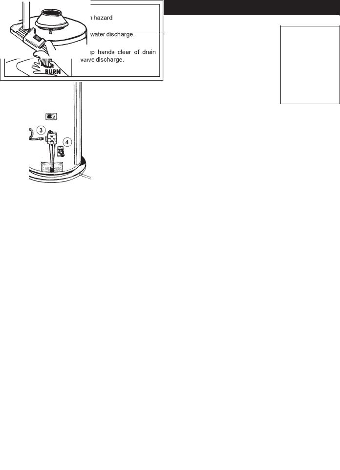
4. Attach a hose to the water heater |
|
|
drain valve and put the other end |
|
|
in a floor drain or outdoors. Open |
|
|
the water heater drain valve. Open |
|
|
a nearby hot water faucet which will |
|
|
relieve pressure in the water |
|
|
heater and speed draining. The |
|
|
water passing out of the drain valve |
|
|
may be extremely hot. To avoid |
|
|
being scalded, make sure all |
|
|
connections are tight and that the |
|
|
water flow is directed away from |
FIGURE4. |
|
any person, see Figures 1 and 4. |
||
|
5.Disconnect the vent pipe from the draft hood where they connect to the water heater. In most installations the vent pipe can be lifted off after any screw or other attached devices are removed. Dispose of the draft hood. The new water heater has the draft hood which must be used for proper operation.
6.If you have copper piping to the water heater, the two copper water pipes can be cut with a hacksaw approximately four inches away from where they connect to the water heater. This will avoid cutting off pipes too short. Additional cuts can be made later if necessary. Disconnect the temperaturepressure relief valve drain line. When the water heater is drained, disconnect the hose from the drain valve. Close the drain valve. The water heater is now completely disconnected and ready to be removed, see Figure 5.
FIGURE5.
If you have galvanized pipe to the water heater, loosen the two galvanized pipes with a pipe wrench at the union in each line. Also disconnect the piping remaining to the water heater. These pieces should be saved since they may be needed when reconnecting the new water heater. Disconnect the temperature-pressure relief valve drain line. When the water heater is drained, disconnect the hose from the drain valve. Close the drain valve. The water heater is now completely disconnected and ready to be removed. Mineral buildup or sediment may have accumulated in the old water heater. This causes the water heater to be much heavier than normal and this residue, if spilled out, could cause staining, see Figure 6.
FIGURE6.
7
TYPICAL INSTALLATION
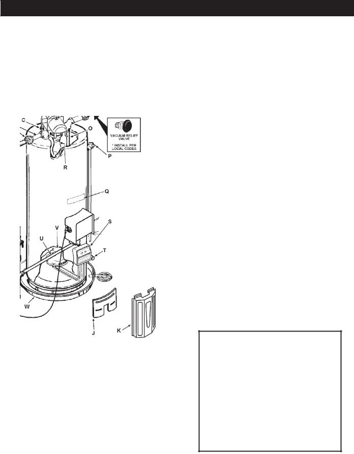
GET TO KNOW YOUR WATER HEATER - GAS MODELS
A |
Vent Pipe |
I |
Drip Leg (Sediment Trap) |
Q |
Rating Plate |
B |
Blower |
J |
Inner Door |
R |
Flue Baffle |
C |
Anode |
K |
Outer door |
S |
Thermostat |
D |
Hot Water Outlet |
L |
Union |
T |
Drain Valve |
E |
Standard Pipe Fittings |
M |
Inlet Water Shut-off Valve |
U |
Pilot and Main Burner |
F |
Gas Supply |
N |
Cold Water Inlet |
V |
Flue |
G |
Manual Gas Shut-off Valve |
O |
Inlet Dip Tube |
W |
Drain Pan |
H |
Ground Joint Union |
P |
Temperature-Pressure Relief Valve |
|
|
*INSTALL INACCORDANCE WITH LOCAL CODES.
*DRIP LEG AS REQUIRED BY LOCAL CODES.
TO VENT TERMINATION |
(S) THERMOSTAT |
ON ROOF |
|
|
|
(U) PILOT & MAIN BURNER
*ALL PIPING MATERIALS TO BE SUPPLIED BY CUSTOMERS.
**CLOSED WATER SYSTEMS ARE THOSE WITH BACK FLOW PREVENTION DEVICES INSTALLED IN THE INLET SERVICE LINE.
FIGURE7.
8

TYPICAL INSTALLATION
MIXING VALVE USAGE
FIGURE8.
This appliance has been design certified as complying with American National Standard/CSA Standard for water heaters and is considered suitable for:
Water (Potable) Heating: All models are considered suitable for water (potable) heating.
HOTTER WATER CAN SCALD:
Water heaters are intended to produce hot water. Water heated to a temperature which will satisfy space heating, clothes washing, dish washing, and other sanitizing needs can scald and permanently injure you upon contact. Some people are
more likely to be permanently injured by hot water than others. These include the elderly, children, the infirm, or physically/ mentally handicapped. If anyone using hot water in your home fits into one of these groups or if there is a local code or state law requiring a certain temperature water at the hot water tap, then you must take special precautions. In addition to using the lowest possible temperature setting that satisfies your hot water needs, a means such as a *Mixing Valve, shall be used at the hot water taps used by these people or at the water heater. Mixing valves are available at plumbing supply or hardware stores. See Figure 8. Valves for reducing point of use temperature by mixing cold and hot water are also available. Consult Maytag Customer Service (1-800-788-8899). Follow mixing valve manufacturer’s instructions for installation of the valves. Before changing the factory setting on the thermostat, read the “Temperature Regulation” section in this manual, see Figure 52 on page 31.
This water heater shall not be connected to any heating system(s) or component(s) previously used with a non-potable water heating appliance.
Toxic chemicals such as used for treatment of boilers or nonpotable water heating appliances shall never be introduced into a potable water space heating system.
NOTE: To protect against untimely corrosion of hot and cold water fittings, it is strongly recommended that di-electric unions or couplings be installed on the water heater when connected to copper pipe.
9

LOCATING THE NEW WATER HEATER
Facts to Consider About the Location
Carefully choose an indoor location for the new water heater, because the placement is a very important consideration for the safety of the occupants in the building and for the most economical use of the appliance. This water heater is not for use in manufactured (mobile) homes or outdoor installation.
Whether replacing an old water heater or putting the water heater in a new location, the following critical points must be observed:
•The location selected should be indoors as close as practical to the vent termination point, and as centralized with the water piping system as possible. The water heater, as all water heaters, will eventually leak. Do not install without adequate drainage provisions where water flow will cause damage.
•40,000 BTU/HR INPUT MODELS - If vented through an outside wall or through the roof, the 3” vent piping cannot exceed a total of 115 feet (50 feet if optional 2” vent piping is used), including vertical and horizontal runs with one 90o elbow. If more elbows are required, the venting distance must be reduced 5 feet for every 90 elbow, see page 22 for vent chart.
•70,000 and 75,000 BTU/HR INPUT MODELS -If vented through an outside wall or through the roof, the 3” vent piping cannot exceed a total of 70 feet (110 feet if optional 4” vent piping is used), including vertical and horizontal runs with one 90o elbow. If more elbows are required, the venting distance must be reduced 5 feet fro every 90 elbow, see page 22 for vent chart.
•Vent piping cannot slope downward and horizontal runs require 1/8” per five foot rise. All horizontal runs require adequate support at 3 1/2 foot intervals and vertical runs supported at 5 foot intervals.
•The water heater requires its own (separate) venting system. It cannot be connected to an existing vent pipe or chimney. It must terminate to the outdoors. Whenever possible terminate the vent on the leeward side of the building if vented through an outside wall. NOTE: Condensation may be created, at times, as the combustion gases exit the vent cap and discoloration of surfaces in proximity to the vent cap may occur.
The power vent water heater requires its own (separate) venting system. It cannot be connected to an existing vent pipe or chimney. It must be terminated to the outdoors. Failure to properly install the venting system can result in asphyxiation, a fire or explosion and can cause DEATH, SERIOUS BODILY INJURY, OR PROPERTY DAMAGE.
•The water heater comes equipped with a 7 foot power cord which can be used to connect to a 110/120 volt power source if (1) local codes allow, and (2) there is a three prong receptacle available. This unit must have a grounded outlet to operate.
Do not use an extension cord. If there is not a suitable receptacle and/or local codes prohibit use of a power cord, field wiring must be provided.
Installation of the water heater must be accomplished in such a manner that if the tank or any connections should leak, the flow will not cause damage to the structure. For this reason, it is not advisable to install the water heater in an attic or upper floor. When such locations cannot be avoided, a suitable drain pan should be installed under the water heater. Drain pans are available at your local hardware store. Such a drain pan must have a minimum length and width of at least 2 inches (51 mm) greater that the water heater dimensions and must be piped to an adequate drain. The pan must not restrict combustion air flow.
Water heater life depends upon water quality, water pressure and the environment in which the water heater is installed. Water heaters are sometimes installed in locations where leakage may result in property damage, even with the use of a drain pan piped to a drain. However, unanticipated damage can be reduced or prevented by a leak detector or water shut-off device used in conjunction with a piped drain pan. These devices are available from some plumbing supply wholesalers and retailers, and detect and react to leakage in various ways:
•Sensors mounted in the drain pan that trigger an alarm or turn off the incoming water to the water heater when leakage is detected.
•Sensors mounted in the drain pan that turn off the water supply to the entire home when water is detected in the drain pan.
•Water supply shut-off devices that activate based on the water pressure differential between the cold water and hot water pipes connected to the water heater.
•Devices that will turn off the gas supply to a gas water heater while at the same time shutting off its water supply.
10
INSTALLATIONS IN AREAS WHERE FLAMMABLE LIQUIDS (VAPORS) ARE LIKELY TO BE PRESENT OR STORED (GARAGES, STORAGE AND UTILITY AREAS, ETC.): Flammable liquids (such as gasoline, solvents, propane [LP or butane, etc.] and other substances such as adhesives, etc.) emit flammable vapors which can be ignited by a gas water heater’s pilot light or main burner. The resulting flashback and fire can cause death or serious burns to anyone in the area, as well as property damage. If installation in such areas is your only option, then installation must be accomplished in a way that the pilot flame and main burner flame are elevated from the floor at least 18 inches. While this may reduce the chances of flammable vapors, from a floor spill being ignited, gasoline and other flammable substances should never be stored or used in the same room or area containing a gas water heater or other open flame or spark producing appliance. NOTE: Flammable vapors may be drawn by air currents from other areas of the structure to the appliance.
Also, the water heater must be located and/or protected so it is not subject to physical damage by a moving vehicle.
Propellants of aerosol sprays and volatile compounds, (cleaners, chlorine based chemicals, refrigerants, etc.) in addition to being highly flammable in many cases, will also change to corrosive hydrochloric acid when exposed to the combustion products of the water heater. The results can be hazardous, and also cause product failure.
This water heater must not be installed directly on carpeting. Carpeting must be protected by metal or wood panel beneath the appliance extending beyond the full width and depth of the appliance by at least 3 inches (76.2 mm) in any direction, or if the appliance is installed in an alcove or closet, the entire floor must be covered by the panel. Failure to heed this warning may result in a fire hazard.
Minimum clearances between the water heater and combustible construction are 0 inch at the sides and rear, 6 inches (152 mm) at the front, and 0 inches from the vent pipe. Clearance from the top of the jacket is 14 inches (356 mm) on most models. Note that a lesser dimension may be allowed on some models, refer to the label attached adjacent to the gas control valve on the water heater, see Figure 9.
FIGURE9.
•Do not obstruct water heater air intake with insulating blanket.
•Gas and carbon monoxide detectors are available.
•Install water heater in accordance with the instruction manual.
A gas water heater cannot operate properly without the correct amount of air for combustion. Do not install in a confined area such as a closet, unless you provide air as shown in the
Locating The New Water Heater section. Never obstruct the flow of ventilation air. If you have any doubts or questions at all, call your gas supplier. Failure to provide the proper amount of combustion air can result in a fire or explosion and cause death, serious bodily injury, or property damage.
FIGURE10.
If this water heater will be used in beauty shops, barber shops, cleaning establishments, or self-service laundries with dry cleaning equipment, it is imperative that the water heater or water heaters be installed so that combustion and ventilation air be taken from outside these areas.
Combustion Air and Ventilation
When determining the installation location for a power vent water heater, snow accumulation and drifting should be considered in areas where applicable.
VENTINGCLEARANCES
•0” clearance for 3” (and optional 2” and 4”) PVC, ABS or CPVC Schedule 40 vent piping from combustible surfaces.
11
•12” minimum from the ground, 9” ceiling overhangs, see Figure 11.
FIGURE11.
•The Power Vent outlet terminal shall terminate at least 36” above any forced air inlet into the building located within 10 feet, see Figure 12.
•The Power Vent outlet terminal shall terminate at least 4 feet below, 4 feet horizontally from or 1 foot above any door, window or gravity air inlet into the building, see Figure 12.
FIGURE12.
•18” minimum from other natural draft (gravity) direct vent, power vent or power direct vent appliance inlet and/or outlet vent(s) when directly above or 135o to either side of the center line, see Figure 13.
FIGURE13.
•24” minimum from any appliance inlet and/or outlet vents when directly below or 45o to either side of center line, see Figure 13.
•18” minimum in all directions from any obstruction that may interfere, see Figure 14.
FIGURE14.
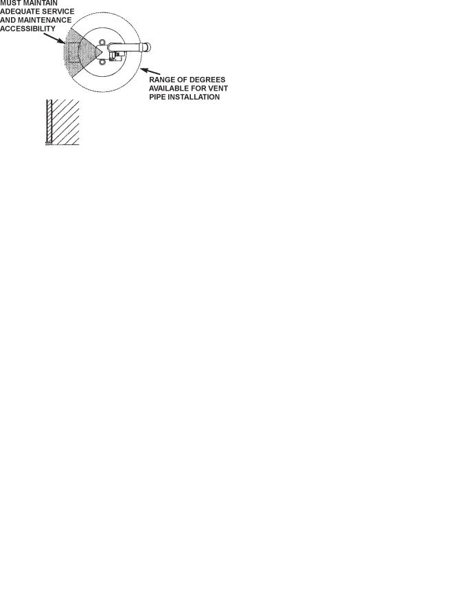
•The location selection must provide clearances for servicing and proper operation of the water heater, see Figure 15.
FIGURE15.
Vent termination must not be within 4 feet of any items such as gas meters, gas valves or other gas regulating equipment.
•The venting system must be installed in a manner which allows inspection of the installation of the venting pipes and joints as well as periodic inspection after installation as required by ANSI Standards.
Vent termination must not be within 4 feet of any items such as gas meters, gas valves or other gas regulating equipment.
Failure to have required clearances between water heater and combustible material will result in a fire hazard.
VENTING THROUGH ROOF - CLEARANCES
•0” clearances for 3” (or optional 2” and 4”) PVC, ABS, or CPVC Schedule 40 piping from combustible surfaces.
•The Power Vent outlet terminal shall terminate at least 18” above the roof surface, see Figure 16.
•The location selection must provide clearances for servicing and proper operation of the water heater, see Figure 15.
•The venting system must be installed in a manner which allows inspection of the installation of the venting pipes and joints as well as periodic inspection after the installation as required by ANSI Standards.
12
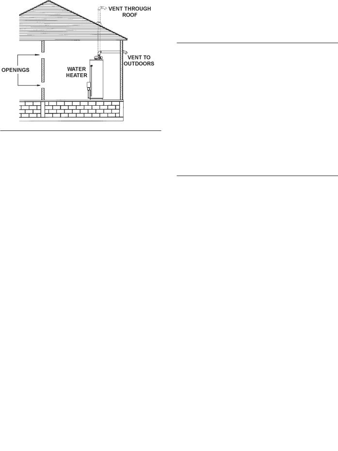
FIGURE16.
Insulation Blankets
•Install water heater in accordance with the instruction manual and
NFPA 54.
•To avoid injury, combustion and ventilation air must be taken from outdoors.
•Do not place chemical vapor emitting products near water heater.
Insulation blankets available to the general public for external use on gas water heaters are not necessary with Maytag products. The purpose of an insulation blanket is to reduce the standby heat loss encountered with storage tank heaters. Your Maytag water heater meets or exceeds the National Appliance Energy Conservation Act standards with respect to insulation and standby loss requirements, making an insulation blanket unnecessary.
Should you choose to apply an insulation blanket to this heater, you should follow these instructions (See Figure 7 for identification of components mentioned below). Failure to follow these instructions can restrict the air flow required for proper combustion, potentially resulting in fire, asphyxiation, serious personal injury or death.
•Do not apply insulation to the top of the water heater, as this will interfere with safe operation of the draft hood.
•Do not cover the outer door, thermostat or temperature & pressure relief valve.
•Do not allow insulation to come within 2” (50.8 mm) of the floor to prevent blockage of combustion air flow to the burner.
•Do not cover the instruction manual. Keep it on the side of the water heater or nearby for future reference.
•Do obtain new warning and instruction labels from Maytag for placement on the blanket directly over the existing labels.
•Do inspect the insulation blanket frequently to make certain it does not sag, thereby obstructing combustion air flow.
Combustion Air and Ventilation for Appliances Located in Unconfined Spaces
UNCONFINED SPACE is space whose volume is not less than 50 cubic feet per 1,000 Btu per hour (4.8 m3 per kW) of the aggregate input rating of all appliances installed in that space. Rooms communicating directly with the space in which the appliances are installed, through openings not furnished with doors, are considered a part of the unconfined space.
In unconfined spaces in buildings, infiltration may be adequate to provide air for combustion, ventilation and dilution of flue gases. However, in buildings of tight construction (for example, weather stripping, heavily insulated, caulked, vapor barrier, etc.), additional air may need to be provided using the methods described in Combustion Air and Ventilation for Appliances Located in Confined Spaces.
Combustion Air and Ventilation for Appliances Located in Confined Spaces
CONFINED SPACE is a space whose volume is less than 50 cubic feet per 1,000 Btu per hour (4.8 m3 per kW) of the aggregate input rating of all appliances installed in that space.
A.ALL AIR FROM INSIDE BUILDINGS:
(See Figure 9 and 10 on page 11 and Figure 17 below)
The confined space shall be provided with two permanent openings communicating directly with an additional room(s) of sufficient volume so that the combined volume of all spaces meets the criteria for an unconfined space. The total input of all gas utilization equipment installed in the combined space shall be considered in making this determination. Each opening shall have a minimum free area of one square inch per 1,000 Btu per hour (22 cm2/kW) of the total input rating of all gas utilization equipment in the confined space, but not less than 100 square inches (645 cm2). One opening shall commence within 12 inches (30 cm) of the top and one commencing within 12 inches (30 cm) of the bottom of the enclosures.
FIGURE17.
13
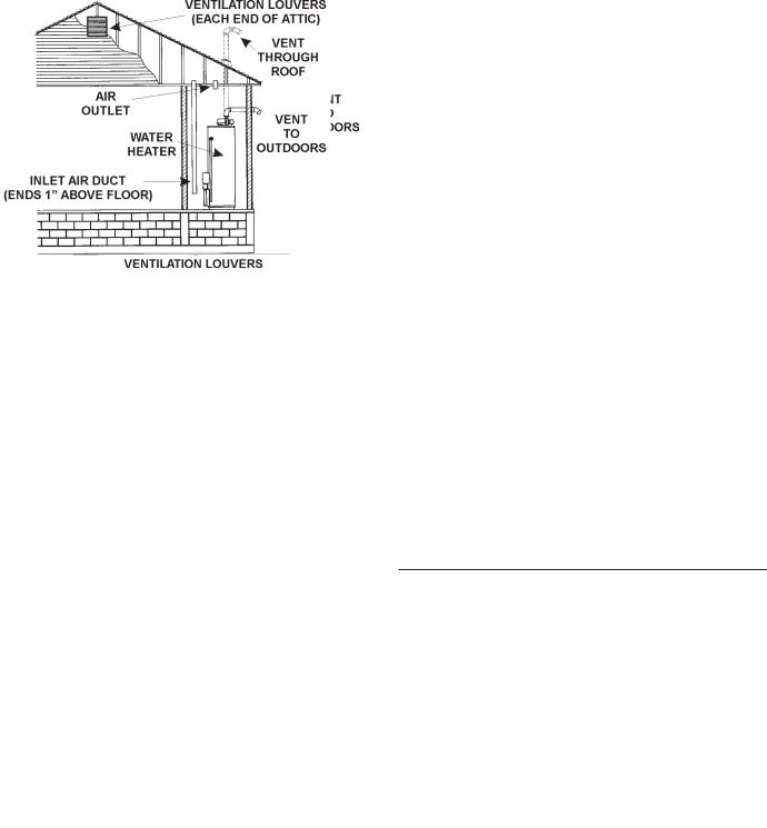
B. ALL AIR FROM OUTDOORS: (See Figures 18, 19 and 20)
The confined space shall be provided with two permanent openings, one commencing within 12 inches (30 cm) of the top and one commencing within 12 inches (30 cm) from the bottom of the enclosure. The openings shall communicate directly, or by ducts, with the outdoors or spaces (crawl or attic) that freely communicate with the outdoors.
FIGURE18.
•When directly communicating with the outdoors, each opening shall have a minimum free area of 1 square inch per 4,000 Btu per hour (5.5 cm2/kW) of total input rating of all equipment in the enclosure, see Figure 18.
•When communicating with the outdoors through vertical ducts, each opening shall have a minimum free area of 1 square inch per 4,000 BTU per hour (5.5 cm2/kW) of total input rating of all equipment in the enclosure, see Figure 19.
FIGURE19.
•When communicating with the outdoors through horizontal ducts, each opening shall have a minimum free area of 1 square inch per 2,000 BTU per hour (11 cm2/kW) of total input rating of all equipment in the enclosure, see Figure 20.
•When ducts are used, they shall be of the same crosssectional area as the free area of the openings to which
they connect. The minimum short side dimension of rectangular air ducts shall not be less than 3 inches (76.2 mm), see Figure 20.
FIGURE20.
•Louvers and Grilles: In calculating free area, consideration shall be given to the blocking effect of louvers, grilles or screens protecting openings. Screens used shall not be smaller than 1/4 inch (6.4 mm) mesh. If the free area through a design of louver or grille is known, it should be used in calculating the size opening required to provide the free area specified. If the design and free area is not known, it may be assumed that wood louvers will be 20-25 percent free area and metal louvers and grilles will have 60-75 percent free area. Louvers and grilles shall be fixed in the open position or interlocked with the equipment so that they are opened automatically during equipment operation.
•Special Conditions Created by Mechanical Exhausting or Fireplaces: operation of exhaust fans, ventilation systems, clothes dryers or fireplaces may create conditions requiring special attention to avoid unsatisfactory operation of installed gas utilization equipment.
Water Piping
HOTTER WATER CAN SCALD:
Water heaters are intended to produce hot water. Water heated to a temperature which will satisfy space heating, clothes washing, dish washing, cleaning and other sanitizing needs can scald and permanently injure you upon contact. Some people are more likely to be permanently injured by hot water than others. These include the elderly, children, the infirm, or physically/mentally handicapped. If anyone using hot water in your home fits into one of these groups or if there is a local code or state law requiring a certain temperature water at the hot water tap, then you must take special precautions. In
14
addition to using the lowest possible temperature setting that satisfies your hot water needs, a means such as a *mixing valve, shall be used at the hot water taps used by these people or at the water heater. Mixing valves are available at plumbing supply or hardware stores, see Figure 8 on page 9 and Figure 21 below. Valves for reducing point of use temperature by mixing cold and hot water are also available. Consult Maytag Customer Service (1-800-788-8899). Follow manufacturer’s instructions for installation of the valves. Before changing the factory setting on the thermostat, read the Temperature Regulation section in this manual.
See Figure 21 for mixing valve usage.
FIGURE21.
This water heater shall not be connected to any heating systems or component(s) used with a non-potable water heating appliance.
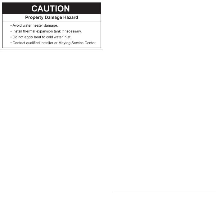
If a water heater installed in a closed water supply system; such as one having a back-flow preventer, check valve, water meter with a check valve, etc. . . in the cold water supply; means shall be provided to control thermal expansion. Contact the local utility or call Maytag Customer Service Center at
1-800-788-8899 for an authorized installer on how to control this situation.
Figure 22 shows the typical attachment of the water piping to the water heater. The water heater is equipped with 3/4” NPT water connections for 40,000 Btuh models and 1 inch water connections for 70,000 and 75,000 Btuh models.
NOTE: If using copper tubing, solder tubing to an adapter before attaching the adapter to the cold water inlet connection. Do not solder the cold water supply line directly to the cold water inlet. It will harm the dip tube and damage the tank.
•Look at the top cover of the water heater. The water outlet is marked “HOT”. Connect the hot water pipe to the hot water outlet on the water heater.
•Look at the top of the water heater. The cold water inlet is marked “COLD”. Connect the cold water pipe to the cold water inlet of the water heater.
NOTE: This water heater is super insulated to minimize heat loss from the tank. Further reduction in heat loss can be accomplished by insulating the hot water lines from the water heater.
NOTE: To protect against untimely corrosion of hot and cold water fittings, it is strongly recommended that di-electric unions or couplings be installed on this water heater when connected to copper pipe.
FIGURE22.
T & P Valve and Pipe Insulation
Remove insulation for T & P valve and pipe connections from carton.
Fit pipe insulation over the incoming cold water line and the hot water line. Make sure that the insulation is against the top cover of the heater.
Fit T & P valve insulation over valve. Make sure that the insulation does not interfere with the lever of the T & P valve.
15
 Loading...