

Mayser SG-SLE X4-0X1 User Manual
Operating Instructions
Polymer Electric
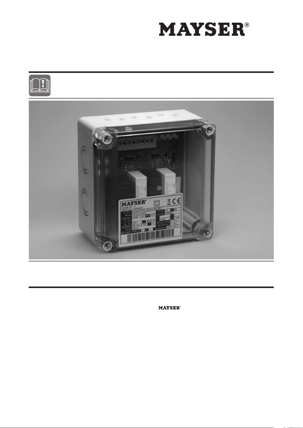
Control Unit SG-SLE X4-0X1
PCB in plastic housing
1000305 SG-SLE 04-051 24 V=
1000786 SG-SLE 04-061 24 V~
7500100 SG-SLE 04-041 115 V~
1000303 SG-SLE 04-021 230 V~
PCB without plastic housing
1000309 SG-SLE 14-051 24 V=
1001156 SG-SLE 14-061 24 V~
1004034 SG-SLE 14-041 115 V~
1000307 SG-SLE 14-021 230 V~
Original instructions
GmbH & Co. KG
Polymer Electric
Örlinger Straße 1–3
89073 Ulm
GERMANY
Tel.: +49 731 2061-0
Fax: +49 731 2061-222
E-Mail: info.ulm@mayser.de
Internet: www.mayser.com
Version 1

Polymer Electric
Content
About these operating instructions ......................................................................................................................... 3
Intended use .............................................................................................................................................................. 4
Safety instructions .................................................................................................................................................... 4
Parts supplied ............................................................................................................................................................ 6
Control Unit SLE 04-0X1 ................................................................................................................................... 6
Control Unit SLE 14-0X1 ................................................................................................................................... 6
Transport and storage ............................................................................................................................................... 6
Packaging and transport.................................................................................................................................... 6
Storage .............................................................................................................................................................. 6
Product overview ....................................................................................................................................................... 7
Connections ..................................................................................................................................................... 7
LEDs information ............................................................................................................................................... 7
Operation, installation and commissioning ............................................................................................................ 8
Operation ...........................................................................................................................................................8
Installation ......................................................................................................................................................... 8
Control Unit SLE 04-0X1 ......................................................................................................................... 9
Control Unit SLE 14-0X1 ....................................................................................................................... 10
Inputs .................................................................................................................................................... 11
Commissioning ................................................................................................................................................ 11
Check operation .................................................................................................................................... 11
Flowchart............................................................................................................................................... 12
Recommissioning ............................................................................................................................................ 12
Automatic reset ..................................................................................................................................... 12
Connection examples ...................................................................................................................................... 13
Contacts continued in two-channel mode ............................................................................................. 13
Excerpt from connection schematics of a gate ...................................................................................... 13
Maintenance and cleaning ...................................................................................................................................... 14
Maintenance .................................................................................................................................................... 14
Cleaning .......................................................................................................................................................... 14
SG-SLE 04-0X1 .................................................................................................................................... 14
SG-SLE 14-0X1 .................................................................................................................................... 14
Troubleshooting and remedies .............................................................................................................................. 15
Replacement parts .......................................................................................................................................... 15
Disposal .................................................................................................................................................................... 16
Conformity ............................................................................................................................................................... 16
EC Design Test ................................................................................................................................................ 16
Technical Data ......................................................................................................................................................... 17
Copyright
The reproduction, distribution and utilization of this document as well as the communication of its contents without express authorization is prohibited. Offenders will be held liable for the payment of damages. All rights reserved in the event of the grant of a patent, utility model or design.
© Mayser Ulm 2012
Page 2/18 Operating Instructions SG-SLE X4-0X1 260612 v2.1

Polymer Electric
Validity
About these operating instructions
These operating instructions are part of the product.
Mayser Polymer Electric accepts no responsibility or warranty claims for damage
and consequential damage due to failure to observe the operating instructions.
Ä Read operating instructions carefully before use.
Ä Keep operating instructions for the complete service life of the product.
Ä Pass operating instructions on to every subsequent owner or user of the pro-
duct.
Ä Add any supplement received from the manufacturer to the operating instruc-
tions.
These operating instructions are only valid for the products specied on the title
page.
Target group
Other applicable
documents
Symbols used
The target group of these operating instructions are operators and trained specialist personnel who are familiar with installation and commissioning.
Ä In addition to the operating instructions, observe the following documents:
- Drawing of the sensor system (optional)
- Wiring diagram (optional)
- Installation instructions of the sensors used
Symbol Meaning
Ä ... Action with one step or with more than one step where
the order is not relevant.
1. ...
2. ...
3. ...
• ...
- ...
(see Assembly) Cross-reference
Action with more than one step where the order is relevant.
Bullets rst level
Bullets second level
260612 v2.1 Operating Instructions SG-SLE X4-0X1 Page 3/18

Polymer Electric
Danger symbols and
information
Symbol Meaning
DANGER Immediate danger leading to death or serious injury.
CAUTION Possible danger which may lead to slight injury or damage
to property.
Information on easier and safer working practices.
Intended use
The Control Unit is designed for signal processing of a pressure-sensitive protective device (PSPD). It evaluates the output signals of sensors with monitoring
resistor 22k1. The integrated output signal switching device (OSSD) transmits the
evaluated safety signals directly to the downstream machine controls.
The Control Unit complies with ISO13849-1:2006 Category3 PLe. So that the
safety classication is retained, the forwarding control must be of the same or a
higher category.
Safety instructions
Ä Do not modify Control Unit
Never manipulate or modify the Control Unit.
Ä Check supply voltage
Check supply voltage. It must correspond with the connecting voltage U
type plate.
Ä Maintain distance
When installing in the switch cabinet, ensure sufficient distance from heat sources (at least 2 cm).
on the
S
Page 4/18 Operating Instructions SG-SLE X4-0X1 260612 v2.1

Polymer Electric
Ä Protect from sunlight
In the case of surface installation, ensure that the Control Unit is protected from
direct sunlight.
Ä Observe pin assignment
Observe pin assignment when connecting the supply voltage.
Ä Insulate contact surfaces
Ensure that contact surfaces not connected to the protective earth are discon-
nected from the power pack and the output circuit by double or reinforced insu-
lation.
Ä SG-SLE 14-0X1 observe protection class
Only use the Control Unit in rooms with a minimum degree of protection of IP54
(e.g. switch cabinet).
Ä Protect relay contacts
Risk of welding: Protect the relay contacts externally.
Ä Fit spark absorbers
When connecting inductive loads, t spark absorbers (RC modules) to the con-
sumer.
Ä Continue redundancy
Make sure you wire the unit directly in the control circuit or that the downstream
control is also in dual channel mode.
Ä Do not overload Control Unit
Ensure that the specied switching current is not exceeded.
Ä Do not cross link Control Unit
Do not cross link the Control Unit with other Control Units.
Terminals 14, 15 and 16, 17 and 18, 19 and 20, 21 are not voltage free.
Ä In the event of a fault, put out of operation
In the event of malfunctions and visible damage, put the Control Unit out of
operation.
Ä Do not use in ATEX zones
Do not use the Control Unit in potentially explosive environments (ATEX). The
Control Unit is not authorised for use in these zones.
260612 v2.1 Operating Instructions SG-SLE X4-0X1 Page 5/18

Polymer Electric
Parts supplied
Control Unit SLE 04-0X1
1× Control Unit
Enclosure with electronics module
1× Operating Instructions
1× Declaration of Conformity
Control Unit SLE 14-0X1
1× Control Unit
PCB with 4× screws M4 and 4× spacers
1× Operating Instructions
1× Declaration of Conformity
Check the scope of supply for completeness and the perfect condition of the product immediately after receipt.
Transport and storage
Packaging and transport
The Control Units are packed individually in cardboard boxes. Several Control
Units are stacked in one large cardboard box.
The documents are enclosed separately.
Storage
Ä Store the Control Units in the original packaging in a dry place.
Ä Observe the storage temperatures given in the technical specications.
Page 6/18 Operating Instructions SG-SLE X4-0X1 260612 v2.1
 Loading...