

Page 1
DIY: A finished Safety Element SE I TPE
in just 8 steps
Before beginning, first switch on the temperature regulating device (260 °C ±
10 °C) for heating the cartridges – it takes the smelter 10 min to warm up!
Polymer Electric
Assembly instructions
DIY SE I TPE
Moulding technology
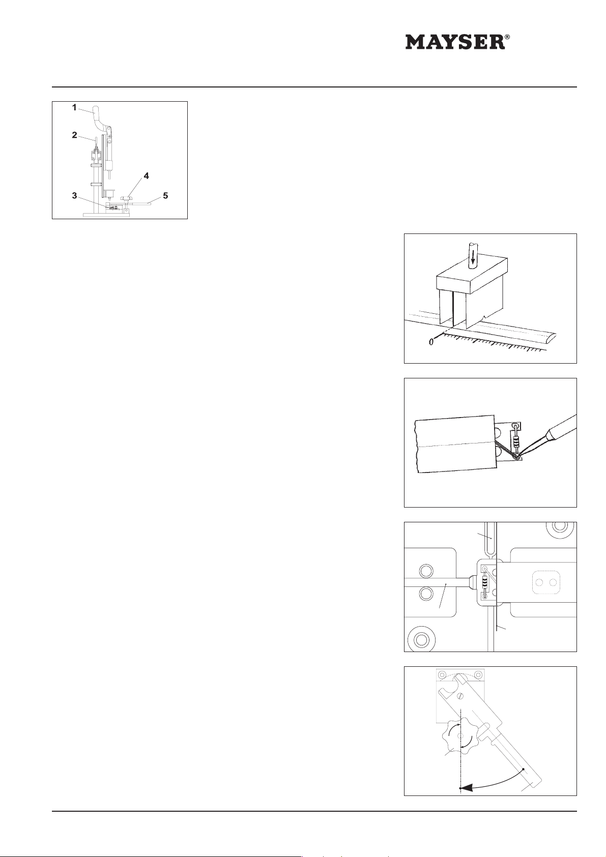
1. Cut contact
tubing
2. Soldering
3. Insert injection
moulds
• Measure off required length of contact
tubing (see instruction card 09/99)
• Place into double cutting device; point
of origin: middle blade
• Make sure that the strands are
centrical to the V-cutouts in the blades
and only then cut.
Caution: Do not damage the strands!
• Strip the insulation of the contact tubing
Caution: Do not damage the strands when
doing so! If as much as one strand gets
cut, the element may not be used
further (reject).
• Insert PCB into contact tubing up to
the centre of the bore holes
• Solder strand to PCB (see diagram)
• Solder other strand in the same way
Use soldering tin as per DIN 8516 F-SW 32
Where should injection-moulds be?
Cable end: without stopper
W-/D-end: insert stopper
• Insert contact tubing, cambering
surface facing upwards
• Position in tool: line contact tubing up
to right edge of squirting channel (see
diagram)
• Close the small quick-action catch
device 3
squirting channel
stopper
alignment line
4. Close tool
Mayser Polymer Electric P. O. Box 30 48 89020 Ulm Germany Tel. +49 731 2061-0 Fax +49 731 2061-222
• Place top part of tool in position,
keeping turning lever 5 in position A
• Put straining screw with star grip 4
into upright position (with left hand)
• Turn turning lever 5 from position A
to position B as far as straining screw
stop (with right hand)
• Tighten straining screw using star grip
4
4
B
A
5
Page 2
Polymer Electric
Assembly instructions
DIY SE I TPE
Moulding technology
DIY: A finished Safety Element SE I TPE
in just 8 steps
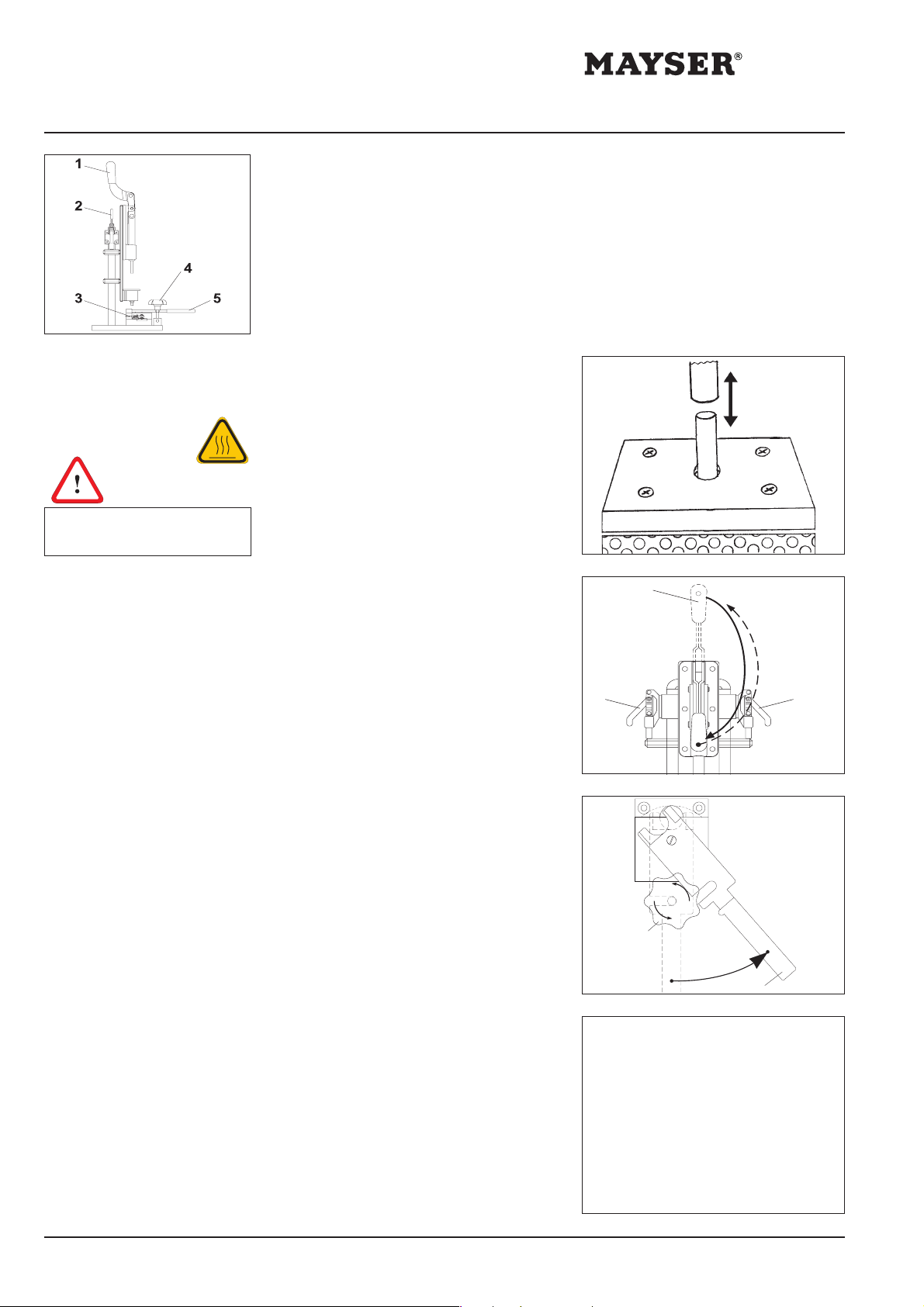
5. Insert squirting
cartridge
Caution: Melting period of 2 min is
imperative! Melting process
otherwise not complete.
6. Injection moulds
7. Remove from
tool
The cartridge must disappear completely
into the smelter opening.
• Put in cartridge and press in gently
with finger; using lever 1, insert
cartridge totally into smelter, exit lever
1 immediately
• Allow for 2 min melting period
Melting period > 5 min: squirt out material
used, clean tool and insert new cartridge
For good injection mould results, carry
out the following briskly:
• Conduct the moving component
downwards using quick-action catch
devices 2, until quick-action catch
devices can be felt latching
• Push lever 1 downwards – in one
impetus – at a constantly fast speed
• Return lever 1 to starting point
• Conduct the moving component back
up again using quick-action catch
devices 2
• Unscrew straining screw using star grip 4
• Set turning lever from position B to
position A
• Unscrew top part of tool and lift off
Tip: use lever action
• Open the small quick-action catch
devices 3 and take out contact tubing
1
22
4
B
A
5
8. Retouch work
and testing
Mayser Polymer Electric P. O. Box 30 48 89020 Ulm Germany Tel. +49 731 2061-0 Fax +49 731 2061-222
• Using a side cutting tool remove
protruding sprue and, if applicable,
any flashes
• Clean tool completely of any remaining
sprue
• Check visually for all round total
injection
• Test function according to criteria in
box opposite
Test for function:
SE1 W with 1.2 kΩ and/or SE1 BK
3.9 V < UOK < 4.1 V
SE1 W with 8.2 kΩ
OK: green LED lights up
SE1 W with 22.1 kΩ
OK: green LED lights up
101202 – MA_SE1-Mould_E.pmd
 Loading...