

Mayser SG-RSV 206-X User Manual
Page 1/4
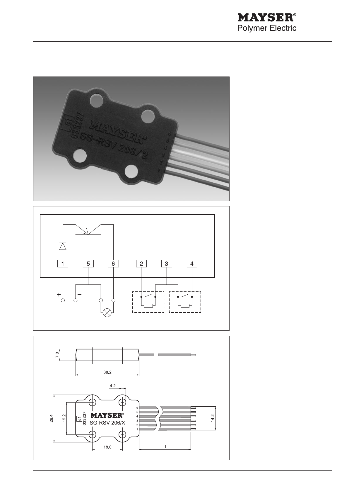
Control Unit SG-RSV 206/X
SG-RSV 206/X
Operating
Instructions
Control Unit
EN 954 Category B
for sensors with
monitoring resistor 1k2.
These operating instructions apply to
the following Control Units:
1002565 SG-RSV 206/112 / 24 V =
Output: pnp not inverted
1003181 SG-RSV 206/2 12 / 24 V =
Output: pnp inverted
Control
This Control Unit contains two monitoring circuits which act on an output
transistor.
The electronics monitor the electrical
resistance of the connected sensors
which have a specic closed-circuit
current.
version 2
brown green blue red orange yellow
U
S
Sensor 1 Sensor 2
SG-RSV 206/1
When the sensors are not activated
(normal operating conditions), there is
no voltage on the output.
When a sensor is activated or a cable
break in the supply lines occurs, there is
voltage on the output.
SG-RSV 206/2
When the sensors are not activated
(normal operating conditions), there is
voltage on the output.
When a sensor is activated or a cable
break in the supply lines occurs, there is
voltage on the output.
Enclosure
W × H × D (mm) 38.2 × 28.4 × 7.0
Cable length L 190 mm
Ends tin-plated
Degree of protection enclosure IP67
Weight (with cable) approx. 15 g
Parts supplied
- Control Unit
Potted electronics with rmly installed
connection wires
- Operating Instructions
Mayser Polymer Electric Postfach 3048 89020 Ulm Germany Tel. +49 731 2061-0 Fax +49 731 2061-222
170409 v2.3

Mayser Polymer Electric Postfach 3048 89020 Ulm Germany Tel. +49 731 2061-0 Fax +49 731 2061-222
170409 v2.3
Page 2/4
Control Unit SG-RSV 206/X
IMPORTANT NOTES! Please read!
To ensure correct and safe operation
of the unit, it must be properly transported and stored, properly installed
and commissioned, and operated in
accordance with its intended use.
Only persons familiar with the installation, commissioning and operation,
and with the corresponding qualications to prove their skills, may work on
the units. They must observe the contents of these operating instructions,
the information stated on the unit and
the relevant safety regulations for the
installation and operation of electrical
systems.
This unit is designed and tested in
accordance with the latest technical
standards and left our factory in a perfectly safe condition. To maintain this
condition, you must observe the safety
regulations marked WARNING! in these
operating instructions. Failure to
observe the safety regulations can lead
to death, injury to personnel, or damage
to the unit and other systems and
equipment.
Should the information given in these
operating instructions be inadequate
in any way, please contact your local
technical centre, subsidiary or representative.
When using the device outside the
Technical Data
Connecting voltage U
SG-RSV 206/1 DC 8 - 32 V
SG-RSV 206/2 DC 8 - 32 V
Power consumption max. 1.0 W
Sensor voltage
Switching thresholds at +23 °C
Sensor activated < 650 Ohm
Cable break > 3k2 Ohm
Output (transistor)
Switching voltage max. U
Switching current max. 50 mA
Response time max. 1 ms
Output type SG-RSV 206/1 pnp not inverted
Output type SG-RSV 206/2 pnp inverted
Connecting cable
Bend radius min. 15 mm
Insulation voltage 1500 V / 50 Hz
Environmental conditions
Permissible ambient temperature - 30 °C to + 80 °C
Humidity max. 85% rel., non-condensing
Vibration fatigue limit 1 g in all 3 levels
S
max. U
S
S
European Union, you must observe
the relevant regulations valid for the
country of use.
Important notes:
Supply voltage
must be in accordance with the
connecting voltage US indicated on
the type plate.
- Permissible temperature range
When installing, maintain sufcient
distance from heat sources
(min. 2 cm).
- if only one sensor
When using only one sensor,
terminate the second input with
Resistor 1k2 ±5% .
 Loading...