

Mayser SG RS 204 User Manual
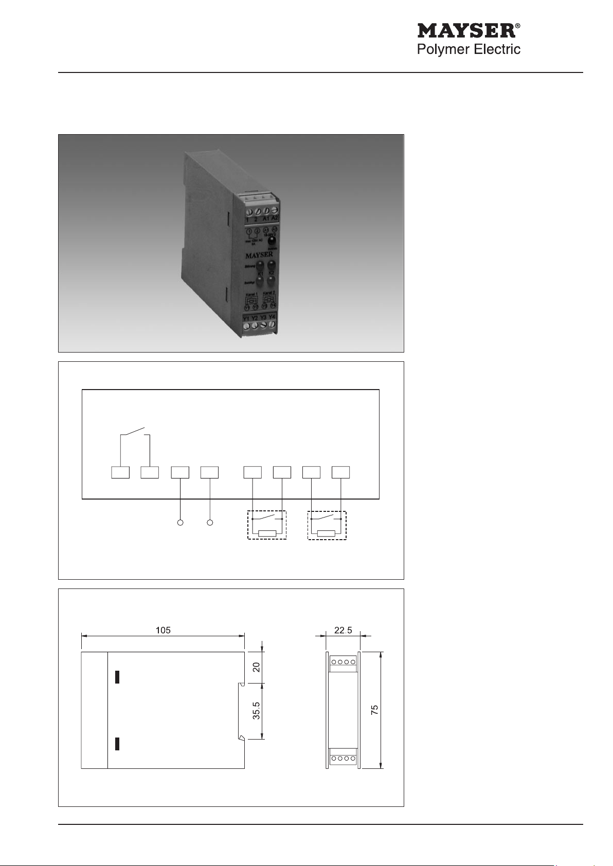
Y3
Y4Y2Y1
21 A2A1
U
s
Control Unit SG-RS 204
sensor 1 sensor 2
Operating
Instructions
Control Unit
EN 954 category 1
for sensors with
monitoring resistor 1.2 kΩ .
These operating instructions apply to
the following Control Units:
1001825 SG-RS 204 12 V=
1001414 SG-RS 204 24 V=/~
1002943 SG-RS 204/invert 12 V=
1002944 SG-RS 204/invert 24 V=/~
Control
This control unit has two monitoring
circuits which operate one output relay.
The electronics monitor the electrical
resistance of the connected sensor,
which operates on a specic closed-circuit currrent.
When the sensors are not activated the
relay is energized (normal operating
conditions).
When a sensor is activated, or if a break
occurs in the power supply, the relay
de-energized.
In the case of Control Unit
SG-RS 204/ invert the relay contact
functions as a NC contact, not as a
NO contact.
Note
When using only one sensor, bridge the
second input with R = 1.2 kΩ
Enclosure
W × H × D (mm) 22.5 × 75 × 105
Degree of protection IP20
Plug connection each 4 channel
Cable terminals max. 2.5 mm
Weight approx. 100 g
Parts supplied
- Control Unit
Enclosure with electronics module
Mayser Polymer Electric Postfach 30 48 89020 Ulm Germany Tel. +49 731 2061-0 Fax +49 731 2061-222
200409 v1.7
and plug-in connectors
- Operating Instructions
2

Installation and Operation
Technical Data
Connecting voltage US
SG-RS 204
AC 24 V DC 18 - 32 V
SG-RS 204/invert DC 10 - 16 V
AC 24 V DC 18 - 32 V
Voltage tolerance -15% to +10%
Nominal frequency 50 Hz
Power consumption < 2 VA < 2 W
Relay Data
Switching voltage max. 125 V AC
Switching current max. 5 A
Permissible ambient temperature
range - 25 °C to + 60 °C
Important notes:
- Supply voltage
must be in accordance with the connecting voltage US indicated on the
type plate.
- Permissible ambient temperature
range
Maintain sufcient distance from heat
sources when mounting into a cabinet
(min. 2 cm).
LED information
- yellow LED "Betätigt K1/K2" (activated K1/K2)
Sensor is activated and relays are
de-energized
- red LED "Störung K1/K2"
(fault K1/K2)
Break in power supply,
Relay de-energized
- green LED "Betrieb" (on)
Line voltage present
DC 10 - 16 V
Installation
Fix the enclosure in any position to an
IEC 60715 35 mm rail.
Wiring takes place in the cable terminals of the plug connection:
Sensor 1 Y1, Y2
Sensor 2 Y3, Y4
Supply voltage A1, A2
Relay 1, 2
CAUTION
Do not disconnect the terminals or
unplug the plug connection with
power on!
Commissioning
After connecting up sensors, relay
contacts and mains, carry out a function
test in the following orde:
Sensor not activated
- Output relay is energized
Sensor activated
- yellow LEDs "Betätigt" (activated)
light up
- Output relay is de-energized
Troubleshooting and remedies
Prerequisite: SG-RS 204 connected to connecting voltage US an sensor.
Sensor not activated and Control Unit does not respond:
LED "Betrieb" (on) off.
> Supply voltage off or incorrect.
Check connecting voltage US, compare with type plate.
Observe correct polarity.
Fault still exists: Control Unit faulty.
Replace Control Unit.
Sensor not activated and relay not energized:
LED "Störung K1/K2" (fault K1/K2) or "Betätigt K1/K2" (activated K1/K2) on.
> Sensor or supply lines faulty (Change in resistance not high enough).
Check sensor with gauge: set value = 1.2 kΩ ±2%
Actual value ≠ set value: sensor or supply line faulty.
Replace sensor.
> Control Unit faulty.
Connect resistor 1.2 kΩ instead of the sensor.
Fault still exists: Control Unit faulty.
Replace Control Unit.
Sensor interrupted and relay not de-energized:
> Control Unit faulty.
Disconnect sensor.
Relay not de-energized: Control Unit faulty.
Replace Control Unit.
Maintenance
The Control Unit is maintenance-free.
Check safety system monthly by
activating the sensors.
Disposal
At the end of their service life, the devices can be returned to us for disposal.
WEEE-Reg.-Nr. DE 39141253
Sensor actuated and relay not de-energized:
> Control Unit faulty
Disconnect sensor
relay not de-energized: Control
Unit faulty
Replace Control Unit.
Fault can still not be detected?
Mayser Support will help:
Tel. +49 731 2061-0
Subject to technical modifications.
Mayser Polymer Electric Postfach 30 48 89020 Ulm Germany Tel. +49 731 2061-0 Fax +49 731 2061-222
200409 v1.7
 Loading...