

Mayser SG-EFS 104-4L User Manual
page 1/4
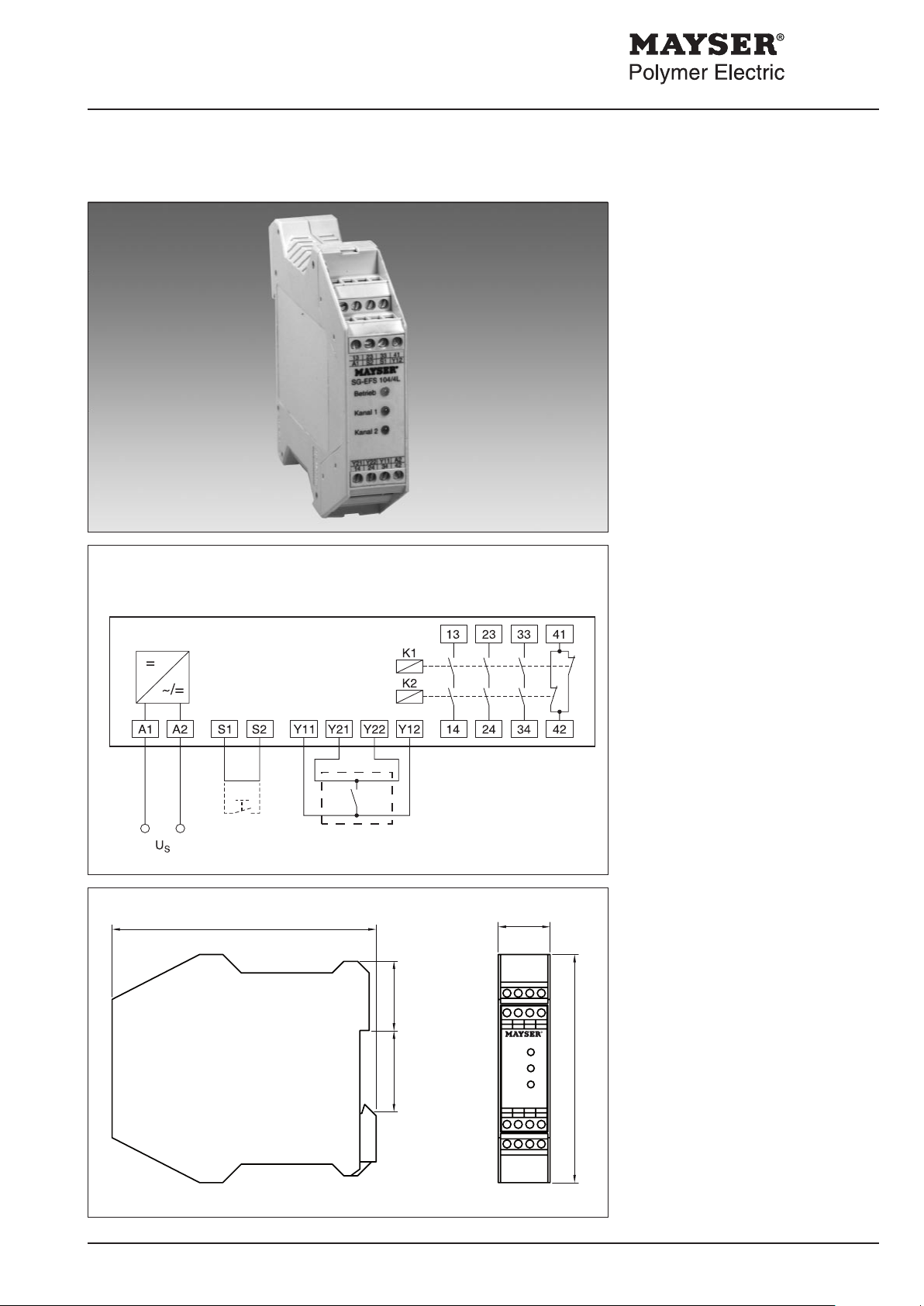
+
Y21 Y22 Y11 A2
14 24 34 42
13
23
33
41
A1 S2S1Y12
Betrieb
Kanal 1
EFS 104/4L
Kanal 2
R
99
114.5
22.5
2935.5
Safety Control Unit SG-EFS 104/4L
Option: with or without reset function
SG-EFS 104/4L
Auto
Operating
Instructions
Safety Control Unit
EEC-type-examination
certicate
EN 954 category 3
SIL2 in accordance with IEC 61508
with forceguided contacts for increased
safety requirements; for BK type sensors.
These operating instructions apply to
the following Control Unit:
SG-EFS 104/4L 24 V =/~
Control system
The single-fault-safe electronics module
has two channels (redundant). Each
channel triggers a forceguided relay.
The relays self-test by contact return
after each switching cycle. The electronic system monitors the connected
BK type sensor. When the sensors are
not activated, both output relays are
energised and both green LEDs light.
If the sensor is activated, or a break
occurs in the supply to the Control Unit,
relays K1 and K2 deenergise and the
LEDs go out.
Start
Sensor
Enclosure
W × H × D (mm) 22.5 × 114.5 × 99
Protection class IP20
Terminals, xed 4× 4-pin
Cable clamps
Solid wire 1× 2.5 mm
Mayser Polymer Electric Postfach 30 48 89020 Ulm Germany Tel. +49 731 2061-0 Fax +49 731 2061-222
240407 v1.2
Strand with sheath 1× 2.5 mm
Solid wire 2× 1.5 mm
Strand with sheath 2× 1.5 mm
Weight approx. 180 g
Parts supplied
- Control Unit
Enclosure with electronic part
- Operating Instructions
2
2
2
2

Mayser Polymer Electric Postfach 30 48 89020 Ulm Germany Tel. +49 731 2061-0 Fax +49 731 2061-222
240407 v1.2
page 2/4
Safety Control Unit SG-EFS 104/4L
SAFETY INSTRUCTIONS! Please read!
• This unit is designed and tested in
accordance with EN 60947-1 and
left the factory in a perfectly safe
condition. To maintain this condition, you must observe the safety
regulations marked "WARNING!" in
these operating instructions. Failure
to observe the safety regulations
can lead to death, injury to personnel, or damage to the unit and other
systems and equipment.
•
To ensure correct and safe operation
of the unit, it must be properly transported and stored, properly installed
and commissioned, and operated in
accordance with its intended use.
•
Only persons familiar with the installation, commissioning and operation,
and with the corresponding qualications to prove their skills, may work on
the units. They must observe the contents of these operating instructions,
the information stated on the unit and
the relevant safety regulations for the
installation and operation of electrical
systems.
•
Repairs, in particular opening the enclosure, may only be carried out by the
manufacturer or a person appointed
by the manufacturer. Otherwise all warranty claims become null and void.
• When using the device outside the
Technical Data
Connecting voltage U
SG-EFS 104/4L AC 24 V DC 24 V
Voltage tolerance -10% to +10% -10% to +10%
Nominal frequency 50 - 60 Hz
Power consumption < 5 VA < 3 W
Sensor
Short-circuit resistance ≤ 400 Ω
Line resistance ≤ 10 Ω
Line length max. 100 m per connection
Control Unit outputs Relays forceguided
Safety circuits 13/14, 23/24, 33/34; normally open contact
Signal circuit 41/42; normally closed contact
Switching voltage max. AC 250 V max. DC 24 V
Switching current max. 5 A max. 5 A
Switching capacity according to
EN 60947-5-1 1,250 VA (AC 15) 120 W (DC13)
Switching operations
mechanical > 1× 10
electrical > 1× 10⁵ (DC 24 V / 2A)
Creep distance and air gap
according to EN 50178 for soiling degree 2, overvoltage
Contact fuse protection external
Normally open contact 6.3 A quick-acting
Normally closed contact 4 A Neozed gL/gG
PFDL Value according to
IEC 61508 4.57 × 10
PFHL Value according to
IEC 61508 1.08 × 10⁻⁸ 1/h
Operating behaviour
Reactivation time < 1 s
Response time < 30 ms
Operating conditions
Permissible ambient
temperature -25 °C to +55 °C
rel. humidity max. 95%
Impact resistance transport 10 g
Impact resistance in operation 2.5 g
S
7
category 3 / 250 V
-5
European Union, you must observe
the relevant regulations valid for the
country of use.
• Should the information given in
these operating instructions be inadequate in any way, please contact
your local technical centre, subsidiary or representative.
Important notes:
- Supply voltage
must be in accordance with the
connecting voltage US indicated
on the type plate.
- Permissible ambient temperature
range
If installing into a cabinet, maintain
sufcient distance from heat sources
(min. 2 cm).
- Wiring
Wire direct to the control circuit or
continue two-channel mode to the
next circuit.
- Fuse relay contacts externally
due to risk of fusion
- Protection class
The units may only be used in locations with a minimum protection class
of IP54 (e.g. cabinet).
Note:
When switching inductive loads the user
must be tted out with spark absorbers.
 Loading...