

Mayser SE 1 TPE Assembly Instructions
Page 1/2
Assembly Instructions SE 1 TPE
Spring contact
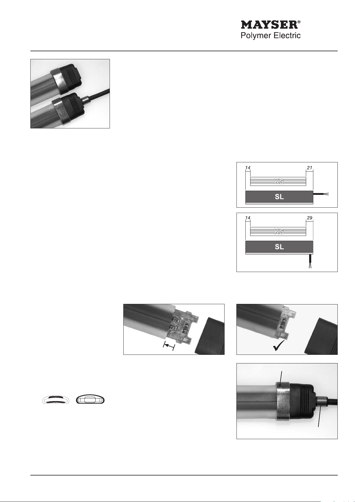
A complete Safety Element SE 1 TPE
in 5 easy steps
These instructions describe cutting of the contact tube to the required length and tting of the end cap on
the resistance side. Fitting is identical on the cable side – apart from the additional sealing ring (round) for
the cable seal.
1. Cut contact tube
2. Assembly
• The contact tube (KS) is always
shorter than the nished Safety Edge
(SL). Measure out required length of
contact tube and mark accordingly.
L
whereby: L
LSL = length of Safety Edge
cable axial: X = 21 mm
cable 90°: X = 29 mm
• Cut to the required length making
sure that the cut edge is straight.
Insert the spring contact PCB into the contact tube as far as the stop position.
= LSL - 14 mm -X
KS
= length of contact tube
KS
2a 2b
3. Position end cap
and sealing ring
contact tube inside of end
cap
Mayser Polymer Electric Postfach 30 48 89020 Ulm GERMANY Tel. +49 731 2061-0 Fax +49 731 2061-222
230412 v1.3 / TNr. 7501801
• Place and position end cap on the
contact tube end. Ensure that the
curvature of the end cap coincides
with the tube curvature (see picture
on left).
Tip: Make a mark 9 mm from the end
of the contact tube. The end cap must
completely cover this mark.
• Position sealing ring (oval) until it is
ush with the end cap.
• On the cable end also position the
sealing ring (round) in the middle.
sealing ring (oval)
sealing ring (round)
Page 2/2
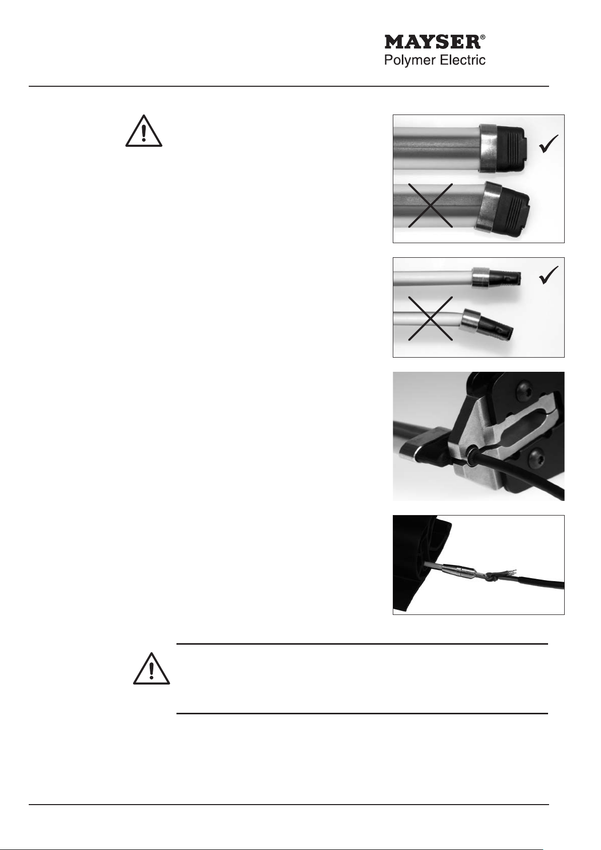
4. Close tool
Prior to closing the tool, ensure that the
contact tube, end cap and sealing ring
are correctly positioned!
If
• the contact tube and end cap are on
the same horizontal
and
• the contact tube and end cap are on
the same vertical line,
then
• close the tool around the sealing ring
(oval). In addition, use the tool on the
the sealing ring (round) at the cable
end – for direction, see picture.
5. Position and test
• Connect up the SE 1 TPE and test for
function.
• Carefully position the complete Safety
Element in the rubber prole of the Safety
Edge.
Tip: The cable pulling device Kati
®
Blitz is
suitable for aiding insertion of the Safety
Element in the rubber prole.
The Safety Element may be irreparably damaged!
Ä Max. permissible pulling force on cable: 30 N
Ä No pressure may be exerted on the contact tube in non-operative mode.
• If necessary, seal both rubber prole ends.
Tip: See "Assembly Instructions for Safety Edges" for the next assembly process.
Mayser Polymer Electric Postfach 30 48 89020 Ulm GERMANY Tel. +49 731 2061-0 Fax +49 731 2061-222
230412 v1.3 / TNr. 7501801
 Loading...