


Contents
About this Concise User Guide .........................................................1
System Startup ..................................................................................4
System Map: Front View with LCD Panel Open .............................5
LED Indicators ..................................................................................6
System Map: Front, Rear, Bottom & Top Views .............................7
System Map: Left & Right Views ....................................................8
Keyboard & Function Keys ..............................................................9
Control Center ......... ........................................................ ................10
3G Module ......................................................................................14
Driver Installation ................................... ............................ ............15
Fingerprint Reader ..........................................................................16
Trusted Platform Module ................................................................17
Intel® vPro™ Technology ..............................................................19
Troubleshooting ..............................................................................20
Specifications ............... ...................................... ............................. 21
Inhalt
Über das Ausführliche Benutzerhandbuch .....................................25
Schnellstart ................. ............... ................ .................. ............... .....28
Systemübersicht: Ansicht von vorne mit geöffnetem
LCD-Bildschirm .............................................................................29
LED-Anzeigen ................................................................................ 30
Systemübersicht: Ansicht von vorne, hinten, unten & oben ...........31
Systemübersicht: Ansicht von links und rechts ..............................32
Tastatur & Funktionstasten .............................................................33
Control Center (Steuerzentrum) .. ....................................................34
3G-Modul ..................... .................. ............... ................ ............... ... 38
Installation der Treiber ....................................................................39
Fingerabdruckleser .................. .................. ............... ................ .......40
TPM (Trusted Platform Module) ............................................... .....41
Intel® vPro™ Technology ..............................................................43
Fehlerbehebung ...............................................................................44
Technische Daten ............................................................................45
Sommaire
A propos de ce Guide Utilisateur Concis ........................................49
Guide de démarrage rapide .............................................................52
Carte du système: Vue de face avec l’écran LCD ouvert ...............53
Indicateurs LED .......................................................................... ....54
Carte du système: Vues de face, arrière, dessous & dessus ............55
Carte du système: Vues de gauche & droite ....... ............................56
Clavier & touches fonction .............................................................57
Control Center (Centre de contrôle) ................................................58
Module 3G .......................................................................................62
Installation du pilote ........................................................................63
Lecteur d'empreintes digitales ...... ...................................................64
TPM (Trusted Platform Module) ....................................................65
Technologie Intel® vPro™ .............................................................67
Dépannage ....................... ........................................ ........................68
Spécifications ..................................................................................69
Contenidos
Acerca de esta Guía del Usuario Concisa .......................................73
Guía rápida para empezar ................................................................76
Mapa del sistema: Vista frontal con panel LCD abierto .................77
Indicadores LED ............. ........................................................ ........78
Mapa del sistema: Vistas frontal, posterior, inferior y superior .....79
Mapa del sistema: Vistas izquierda y derecha ................................80
Teclado & teclas de función .................. ..........................................81
Control Center (Centro de control) .................. ... ............................82
Módulo 3G ......................................................................................86
Instalación de controladores ............................................................87
Lector de huellas digitales ...............................................................88

TPM (Trusted Platform Module) ............................................... .....89
Intel® vPro™ Technology ..............................................................91
Solución de problemas ........ ....................................................... .....92
Especificaciones ............... .................. ................ ............... ..............93
Sommario
Informazioni sulla Guida Rapida per l'Utente ................................97
Guida di avvio rapido ....................................................................100
Descrizione del sistema: Vista anteriore con pannello
LCD aperto ....................................................................................101
Indicatori LED ..............................................................................102
Descrizione del sistema: Vista anteriore, posteriore, inferiore e
dall'alto .........................................................................................103
Descrizione del sistema: Vista sinistra e destra ............................104
Tastiera & tasti funzione ...............................................................105
Control Center (Centro di controllo) .......................................... ...106
Modulo 3G ....................................................................................110
Installazione driver ........................................................................111
Lettore d’impronte digitali ........................................................... .112
TPM (Trusted Platform Module) ............................................... ...113
Intel® vPro™ Technology ............................................................115
Risoluzione dei problemi ..............................................................116
Specifiche tecniche .......................................................................117

1
English
About this Concise User Guide
This quick guide is a brief introduction to getting your system started. This is a supplement, and not a substitu te for the
expanded English language User’s Manual in Adobe Acrobat format on the Device Drivers & U tilities + User’s Manual
disc supplied with your computer. This disc also contains the drivers and utilities necessary for the prop er oper ation of
the computer (Note: The company reserves the right to revise this publication or to change its contents without notice).
Some or all of the computer’s features may already have been setup. If they aren’t, or you are planning to re-configure
(or re-install) portions of the system, refer to the expanded User’s Manual. The Device Drivers & Utilities + User’s
Manual disc does not contain an operating system.
Regulatory and Safety Information
Please pay careful attention to the full regulatory notices and safety information contained in the expanded User’s Manual on the Device Drivers & Utilities + User’s Manual disc.
© August 2012
Trademarks
Intel and Intel Core are trademarks/registered trademarks of Intel Corporation.
FCC Statement
This device complies with Part
15 of the FCC Rules. Operation
is subject to the following two
conditions:
1.This device may not cause
harmful interference.
2.This device must accept any
interference received, including interference that may
cause undesired operation.

2
English
Instructions for Care and Operation
The computer is quite rugged, but it can be damaged. To prevent this, follow these suggestions:
• Don’t drop it, or expose it to shock. If the computer falls, the
case and the components could be damaged.
• Keep it dry, and don’t overheat it. Keep the computer and power
supply away from any kind of heating element. This is an electrical appliance. If water or any other liquid gets into it, the computer
could be badly damaged.
• Avoid interference. Keep the com puter away from high capacity
transformers, electric motors, and other strong magnetic fields.
These can hinder proper performance and damage your data.
• Follow the proper working procedures for the computer. Shut
the computer down properly and don’t forget to save your work.
Remember to periodically save your data as data may be lost.
Servicing
Do not attempt to service the computer yourself. Doing so may
violate your warranty and expose you and the computer to
electric shock. Refer all servicing to authorized service personnel. Unplug the computer from the power supply. Then refer
servicing to qualified service personnel under any of the fo llowing conditions:
• When the power cord or AC/DC adapter is damaged or frayed.
• If the computer has been exposed to any liquids.
• If the computer does not work normally when you follow the operating instructions.
• If the computer has been dropped or damaged (do not touch the
poisonous liquid if the LCD panel breaks).
• If there is an unusual odor, heat or smoke coming from your computer.
Safety Information
• Only use an AC/DC adapter approved for use with this computer.
• Use only the power cord and batteries indicated in this manual. Do
not dispose of batteries in a fire. They may explode. Check with
local codes for possible special disposal instructions.
• Do not continue to use a battery that has been dropped, or that
appears damaged (e.g. bent or twisted) in any way. Even if the
computer continues to work with a damaged battery in place, it
may cause circuit damage, which may possibly result in fire.
• Make sure that your computer is completely powered off before
putting it into a travel bag (or any such container).
• Before cleaning the computer, make sure it is disconnected from
any external power supplies, peripherals and cables (including
telephone lines). It is advisable to also remove your battery in
order to prevent accidentally turning the machine on.
• Use a soft clean cloth to clean the computer, but do not apply
cleaner directly to the computer. Do not use volatile (petroleum
distillates) or abrasive cleaners on any part of the computer.
• Do not try to repair a battery pack. Refer any battery pack repair or
replacement to your service representative or qualified service personnel.
• Note that in computer’s featuring a raised LCD electro-plated
logo, the logo is covered by a protective adhesive. Due to general
wear and tear, this adhesive may deter iorate over time and the
exposed logo may develop sharp edges. Be careful when handling
the computer in this case, and avoid touching the raised LCD electro-plated logo. Avoid placing any other items in the carrying bag
which may rub against the top of the computer during transport. If
any such wear and tear develops contact your service center.

3
English
Polymer Battery Precautions
Note the following information which is specific to poly mer
batteries only, and where applicable, this overrides the general
battery precaution information.
• Polymer batteries may experience a slight expansion or swelling,
however this is part of the battery’s safety mechanism and is not a
cause for concern.
• Use proper handling procedures when using polymer batteries. Do
not use polymer batteries in high ambient temperature environments, and do not store unused batteries for extended periods.
Battery Disposal & Caution
The product that you have purchased contains a rechargeable
battery. The battery is recyclable. At the end of its useful life,
under various state and local laws, it may be illegal to dispose
of this battery into the municipal waste stream. Check with
your local solid waste officials for details in your area for recycling options or proper disposal.
Danger of explosion if battery is incorrectly replaced. Replace
only with the same or equivalent type recommended by the
manufacturer. Discard used battery according to the manufacturer’s instructions.

4
English
System Startup
1. Remove all packing materials.
2. Place the computer on a stable surface.
3. Insert the battery and make sure it is locked in position.
4. Securely attach any peripherals you want to use with the
computer (e.g. keyboard and mouse) to their ports.
5. Attach the AC/DC adapter to the DC-In jack on the left of the
computer, then plug the AC power cord into an outlet, and
connect the AC power cord to the AC/DC adapter.
6. Use one hand to raise the
lid/LCD to a comfortable viewing angle
(do not exceed 135 degrees); use the other hand (as illustrated
in Figure 1) to support the base of the computer (Note: Never
lift the computer by the lid/LCD).
7. Press the power button to turn the computer “on”.
System Software
Your computer may already come with system software
pre-installed. Where this is not the case, or where you are
re-configuring your computer for a different system, you
will find this manual refers to Microsoft Windows 7.
Model Differences
This notebook series includes two different models (see
Specifications on page 21 for details).
Figure 1 - Opening the Lid/LCD/Computer with AC/DC
Adapter Plugged-In
Shut Down
Note that you should always shut your computer down by
choosing Shut Down
from the Start Menu.
This will help prevent
hard disk or system
problems.
135 ゚

5
English
System Map: Front View with LCD Panel Open
Figure 2
Front View with LCD Panel
Open
1. PC Camera (Optional)
2. LCD
3. Power Button
4. LED Indicators
5. Keyboard
6. Built-In Microphone
7. Touchpad & Buttons
8. Fingerprint Reader
7
Wireless Device
Operation Aboard
Aircraft
The use of any portable
electronic transmission
devices aboard aircraft
is usually prohibited.
Make sure the wireless
modules are OFF if
you are using the computer aboard aircraft.
Use the key combinations (or WLAN Switch
for wireless LAN only)
to toggle power to the
3G/WLAN/Bluetooth
modules, and check the
LED indicator/visual indicator to see if the modules are powered on or
not (see Table 2 on
page 6 and Table 3 on
page 9).
Note that the Touchpad and Buttons
valid operational area is that indicated within the red dotted lines above.
2
4
1
3
5
6
8
7
6
English
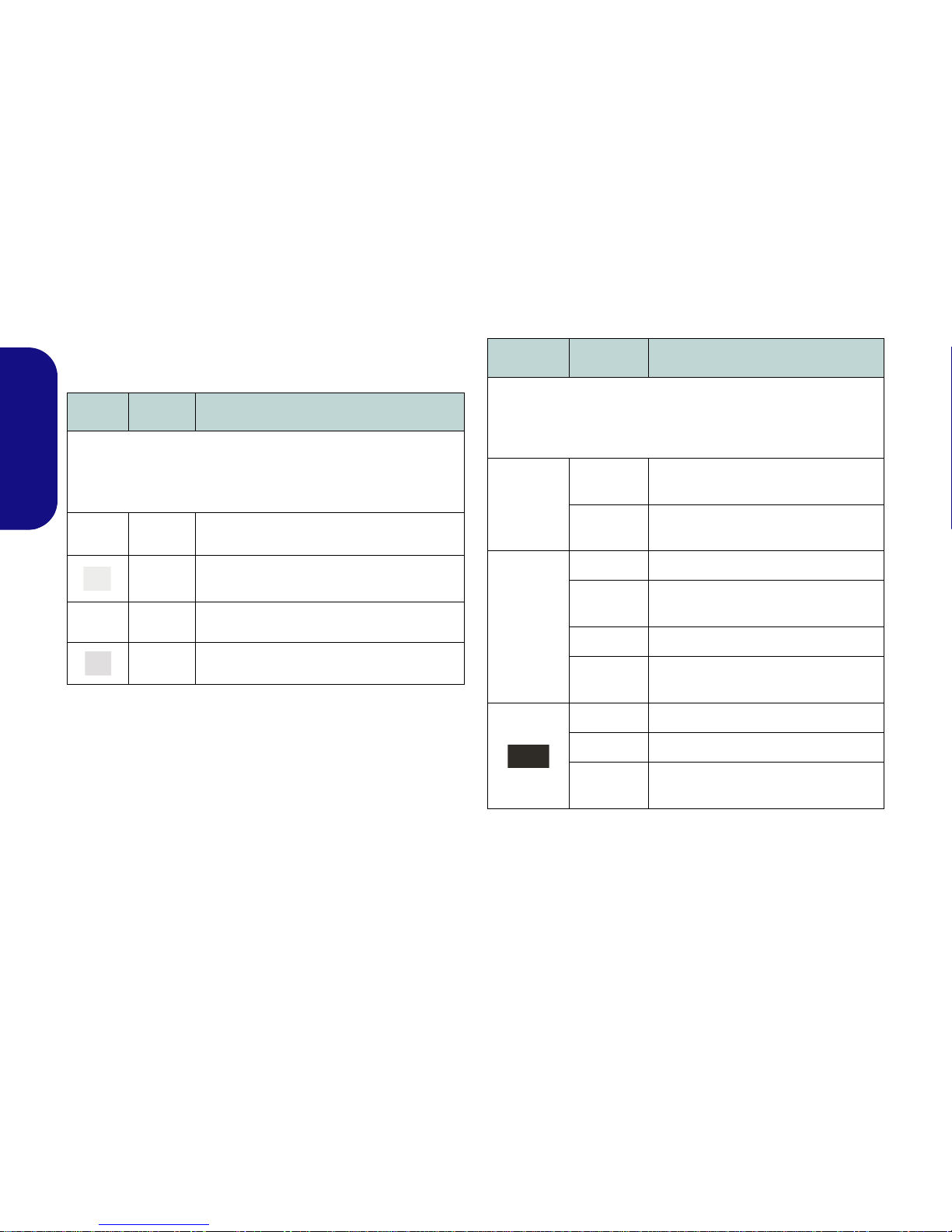
LED Indicators
The LED indicators on the computer display helpful information about the current status of the computer.
Table 1 - LED Status Indicators
Table 2 - LED Power Indicators
Icon Color Description
Green Hard Disk Activity
Green
Number Lock (Numeric Keypad) Acti-
vated
Green Caps Lock Activated
Green Scroll Lock Activated
Icon Color Description
Green
The Wireless LAN Module is Pow-
ered On
Orange
The Bluetooth Module is Powered
On
Orange The AC/DC Adapter is Plugged In
Blinking
Orange
The powered USB Port is on
(see page 8)
Green The Computer is On
Blinking
Green
The Computer is in Sleep Mode
Orange The Battery is Charging
Green The Battery is Fully Charged
Blinking
Orange
The Battery Has Reached Critically
Low Power Status

7
English
System Map: Front, Rear, Bottom & Top Views
3
5
1
2
Rear
Front
4
7
6
8
9
9
Figure 3
Front, Rear, Bottom &
Top Views
1. LED Indicators
2. WLAN Switch
3. Security Lock Slot
4. Battery
5. Docking Port
6. Vent
7. Component Bay Cover
8. Hard Disk Bay Cover
9. Speakers
10. Docking Station
(Optional)
WLAN Switch
Use the WLAN
Switch (for Wireless
LAN only) to toggle
power to the WLAN
module. The position
of the WLAN switch
governs the power
status of the WLAN
module at startup,
and upon resuming
from a power saving
state.
Docking
.If your purchase includes the docking station, open the docking port cover latch and align the
computer with the placeholder on the docking station (see the accompanying docking station for
full details of the docking procedure).
6
6
4
10

8
English
System Map: Left & Right Views
Figure 4
Left & Right Views
1. DC-In Jack
2. External Monitor Port
3. RJ-45 LAN Jack
4. e-SATA Port
5. Vent
6. Powered USB 3.0
Port
7. 2 * USB 3.0 Ports
8. HDMI-Out Port
9. ExpressCard/54(34)
Slot
10. Multi-in-1 Card
Reader
11. Microphone-In Jack
12. Headphone-Out Jack
13. USB 2.0 Port
14. Optical Device Drive
Bay
15. Emergency Eject Hole
1
8
9
3
5
2
Right
4
10
12
6
Bottom
Left
13
Docking Port Cover
If your purchase option includes the docking
station, make sure you keep the cover closed
when the computer is not docked in the station.
This will help prevent foreign objects and/or
dust getting in to the contact area. If your purchase option does not include the docking station, an insert will be provided to prevent
accidentally opening the docking port. Do not
attempt to open the cover or remove the insert
in this case.
Overheating
To prevent your computer from overheating
make sure nothing blocks any vent while the
computer is in use.
USB
The USB 3.0 ports are colored blue. USB
3.0 will transfer data much faster than
USB 2.0, and is backwards-compatible
with USB 2.0. When the powered USB 3.0
port is on it will supply power (for
charging devices only, not for operating devices) when the system is off but
still powered by the AC/DC adapter
plugged into a working outlet, or powered
by the battery with a capacity level above
20% (this may not work with certain devices - see page 20). Toggle power to this
port by using Fn + power button.
6
14
7
7
15
11
9
English
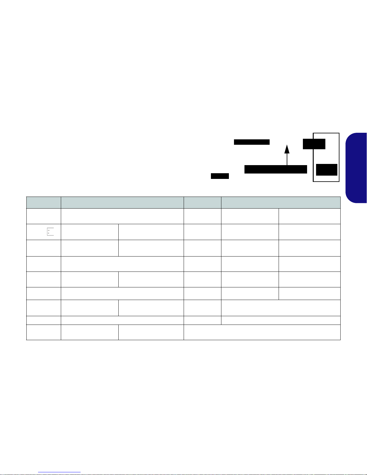
Keyboard & Function Keys
The keyboard includes a numeric keypad for easy numeric
data input. Pressing NumLk turns on/off the numeric keypad. It also features function keys to allow you to change
operational features instantly. The function keys (F1 - F12
etc.) will act as hot keys when pressed while Fn is held
down. In addition to the basic function key combinations,
visual indicators are available when the hot key driver is installed.
Keys Function/Visual Indicat ors Keys Function/Visual Indicators
Fn + ~ Play/Pause (in Audio/Video Programs) Fn + F10
PC Camera Power
Toggle
Fn +
3G Module Power Tog-
gle
Fn + F11
WLAN Module Power
Toggle
Fn + F1 Touchpad Toggle Fn + F12
Bluetooth Module
Power Toggle
Fn + F2
Turn LCD Backlight Off
(Press a key to or use Touchpad to turn on)
Fn + NumLk Number Lock Toggle
Fn + F3 Mute Toggle Fn + ScrLk Scroll Lock Toggle
Fn + F4 Sleep Toggle Caps Lock Caps Lock Toggle
Fn + F5/F6
Volume Decrease/
Increase
Fn + Power
Button
Powered USB Port Power Toggle (see page 20)
Fn + F7 Display Toggle Fn + Esc Control Center Toggle (see page 10)
Fn + F8/F9
Brightness Decrease/
Increase
Table 3 - Function Keys & Visual Indicators
Function Keys
Numeric
Keypad
Fn Key
3G Module Power Toggle
NumLk &
ScrLk
Figure 5 - Keyboard

10
English
Control Center
Press the Fn + Esc key combination to toggle the Control Center on/off. The Control Center gives quick access to
frequently used controls, and enables you to quickly turn modules on/off.
Figure 6 - Control Center
Click on any button to turn any of the modules (e.g. TouchPad, Camera) on/off. Click on Power Conservation to switch
between Performance, Balanced or Energy Star modes. Click on the buttons (or just click and hold the mouse button)
to adjust the slider for Brightness/Volume. Click on Display Switch/Time Zone/ Desktop Background to bring up
the appropriate Windows control panel. Click on the Sleep button to put the computer into Hibernate or Sleep modes.
Undocking
Click the Docking button
to hot undock the system
(if your computer supports hot undocking). An
Undock Complete message will appear in the
taskbar when undocking
is complete.
Wireless & Bluetooth
Modules are Off
11
English
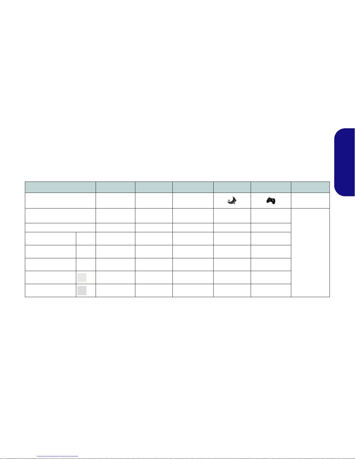
Power Modes
You can set a Power Mode by clicking the appropriate icon at the top of the Control Center. Each power mode will
affect the power status of modules (e.g. WLAN, Bluetooth, 3G or Camera), screen brightness, TouchPad power and
Silent Mode. You can click a Control Center icon to set an overall power mode and then click individual icons in the
Control Center to power on/off any modules etc.
Table 4 illustrates the basic settings for each power mode. If you choose user defined the settings will correspond to
your selected system settings.
Table 4 - Power Modes
Modes Power Saving Flight Entertainment Quiet Performance User Defined
Icon
Power Plan Power Saver Balanced Power Saver Power Saver
High Perfor-
mance
User Defined
Power Conservation Mode Energy Star BIOS Default Energy Star Energy Star Performance
Brightness 14 42 100 42 100
WLAN OFF OFF ON ON ON
3G OFF OFF OFF OFF OFF
PC Camera OFF OFF OFF ON ON
Touchpad ON ON ON ON ON

12
English
Power Status
The Power Status icon will show whether you are currently powered by the battery, or by the AC/DC adapter plugged
in to a working power outlet. The power status bar will show the current battery charge state.
Brightness
The Brightness icon will show the current screen brightness level. You can use the slider to adjust the screen brightness
or the Fn + F8/F9 key combinations, or use the Fn + F2 key combination to turn off the LED backlight (press any key
to turn it on again). Note that screen brightness is also effected by the Power Mode selected.
Volume
The Volume icon will show the current volume level. You can use the slider to adjust the volume or the Fn + F5/F6
key combinations, or use the Fn + F3 key combination to mute the volume.
Power Conservation
This system supports Energy Star power management features that place computers (CPU, hard drive, etc.) into a lowpower sleep modes after a designated period of inactivity. Click either the Performance, Balanced or Energy Star
button.
Sleep
Click the Sleep button to bring up the Hibernate or Sleep buttons, and click either button to have the computer
enter the appropriate power-saving mode.

13
English
Display Switch
Click the Display Switch button to access the menu (or use the + P key combination) and select the appropriate
display mode.
Time Zone
Clicking the Time Zone button will access the Date and Time Windows control panel.
Desktop Background
Clicking the Desktop Background button will allow you to change the desktop background picture.
TouchPad/PC Camera/Wireless LAN Module /Bluetooth/3G Module
Click any of these buttons to toggle the TouchPad or module’s power status. A crossed out icon will appear over the top
left of the icon when it is off
. Note that the power status of a module, and TouchPad power, is also effected by the
Power Mode selected.
Docking
Click the Docking button to prepare the system for docking/undocking.
Caps Lock/Scroll Lock/ Number Lock
Click the button to toggle the appropriate lock mode.

14
English
3G Module
If you have included an optional 3G module in your purchase option, follow the instructions below to install the
USIM card (which will be provided by your service provider), and then run the appropriate application supplied
with your module.
USIM Card Insertion
1. Turn off the compute r, and turn it over and remove the battery
(slide the latches in the direction indicated below and slide
the battery out).
Figure 7 - Remove the battery
2. Insert the USIM card as illustrated below until it clicks into
position, and replace the battery.
Figure 8 - Insert the USIM Card
1
1
USIM Card Orientation
Note that the USIM card’s readable side (with the gold-colored contacts) should face upwards as illustrated.

15
English
Driver Installation
The Device Drivers & Utilities + User’s Manual disc contains the drivers and utilities
necessary for the proper operation of the computer. This setup will probably have already been done for you. If this is not the case, insert the disc and click Install Driv-
ers (button), or Option Drivers (button) to access the Optional driver menu. Install
the drivers in the order indicated in Figure 9. Click to select the drivers you wish
to install (you should note down the drivers as you install them). Note: If you need to
reinstall any driver, you should uninstall the driver first
.
If the Found New Hardware wizard appears during the installation procedure, click
Cancel to close the window, and follow the installation procedure as directed.
Driver Installation General
Guidelines
As a general guide follow the
default on-screen instructions
for each driver (e.g. Next >
Next > Finish) unless you are
an advanced user. In many
cases a restart is required to
install the driver.
Make sure any modules (e.g.
PC Camera, WLAN or 3G)
are ON before installing the
appropriate driver.
Windows Update
After installing all the drivers
make sure you enable Win-
dows Update in order to get
all the latest security updates
etc. (all updates will include
the latest hotfixes from Microsoft).
Driver Installation & Power
When installing drivers make sure
your computer is powered by the
AC/DC adapter connected to a
working power source. Some drivers draw a significant amount of
power during the installation procedure, and if the remaining battery
capacity is not adequate this may
cause the system to shut down and
cause system problems (note that
there is no safety issue involved
here, and the battery will be rechargeable within 1 minute).
Figure 9 - Install Drivers

16
English
Fingerprint Reader
Enroll your fingerprints as instructed below before use.
User Enrollment
1. Click Start > Programs/All Programs > Protector Suite >
Control Center, or double click the taskbar icon .
2. On the first run of the program you will be asked to click the
Accept button to accept the license.
3. If you have not set a Windows password you will be prompted
to do so (note: If you have not set a password Protector Suite
QL cannot secure access to your computer).
4. Click Submit when you have entered password.
5. You will then be prompted to enroll your fingerprints (you can
click Tutorial to get help with fingerprint enrollment at any time).
6. Click the button above any of the fingers to begin the enrollment
process for that finger.
7. Swipe the finger until the progress bar reaches 100% to enroll
that finger.
8. Repeat the process for all the fingers you wish to enroll, and
then click Save and Continue.
9. Enter a backup password and click Apply.
10. Close the fingerprint status window.
11. You can also run the Tutorial, or Product Tour (to run the
product tour video) to get more information.
12. Right-click the taskbar icon to Start Control Center to allow
you to Edit Fingerprints, register Applications, and access
the Help menu etc.
13. If you swipe your finger over the reader at any time you can
access the Biomenu to lock the computer, register
websites, access the Personal Safe or E-Wallet, open the
Control Center and access the Help menu.
Figure 10 - Control Center & Biomenu
Fingerprint Enrollment
Note that it is strongly recommended that you enroll
more than one finger in
case of injury etc.

17
English
Trusted Platform Module
Before setting up the TPM functions you must initialize
the security platform.
Activating TPM
1. Restart the computer.
2. Enter the Aptio Setup Utility pressing F2 during the POST.
3. Use the arrow keys to select the Security menu.
4. Select TPM Configuration and press Enter.
5. Select TPM Support and press Enter . Select Enable and press
Enter.
6. Select TPM St ate, press Enter and select Enable to change the
TPM state to enabled. You will then need to press F4 to save
the changes and restart the computer.
7. As the computer restarts press F2 to enter the BIOS again and
go to the TPM Configuration menu.
8. Select Pending TPM operation, press Enter and select the
option you require (if you are initializing TPM you should select
Enable Take Ownership). You will then need to press F4 to
save the changes and restart the computer.
9. You can now install the TPM driver and then initialize the TPM.
TPM Driver Installation
1. Click Option Drivers (button).
2. Click 7.Install TPM Driver > Yes.
3. Click Install > Next.
4. Click the button to accept the license and click Next.
5. Click Next > Next > Install.
6. Click Finish > Yes to restart the computer.
Initializing TPM
1. Run the application from the Infineon Security Platform Solution > Manage Security Platform item in the Start > Programs/All Programs menu.
2. Click User Settings (tab) and click Yes, or right-click the icon
in the notification area of the taskbar, and select Security
Platform Initialization (or click the Security Platform S tate
taskbar bubble).
3. The Quick Initialization method will automatically be selected
for you (if you need to use advanced settings provided by your
network administrator then select Advanced Initialization).
4. You will need to use a removable media (e.g. a USB Flash
Drive) to store passwords and data (keep the media in a safe
place until required).
Figure 11 - Security Platform Quick Initialization Wizard
5. Select the drive you want to use from the drop-down menu and
click Next.

18
English
6. Choose the Security Platform Features you want to use by
clicking the appropriate tickbox.
7. Enter a Basic User Password (and re-type to confirm it) and
click Next.
8. Click Next to confirm the settings.
9. The computer will then initialize the settings.
10. Click Finish.
11. Click the tabs and control panels to adjust the settings.
12. Double-click the taskbar icon to access the Infineon
Security Platform Settings T ool , or right-click the taskbar icon
and select a menu item.
Infineon Security Platform Settings
Tool
The Infineon Security Platform Settings Tool allows you
to manage and check the TPM state, manage your password information, and to backup and restore the TPM data. As TPM is usually administered within large
enterprises and organizations, your system administrator
will need to assist you in managing the information here.
Figure 12 - Infineon Security Platform Settings Tool
19
English
Intel® vPro™ Technology
Intel® vPro™ Technology is supported by Model B
computers only. This set of technology features, built
into the computer’s motherboard, allows Information
Technology departments remote access to the computer.
This allows the IT department to monitor, maintain and
manage computers regardless of the state of the operating
system or the computer’s power state. This can be done
over a wired or corporate wireless network, or even outside the corporate firewall through a wired LAN connection.
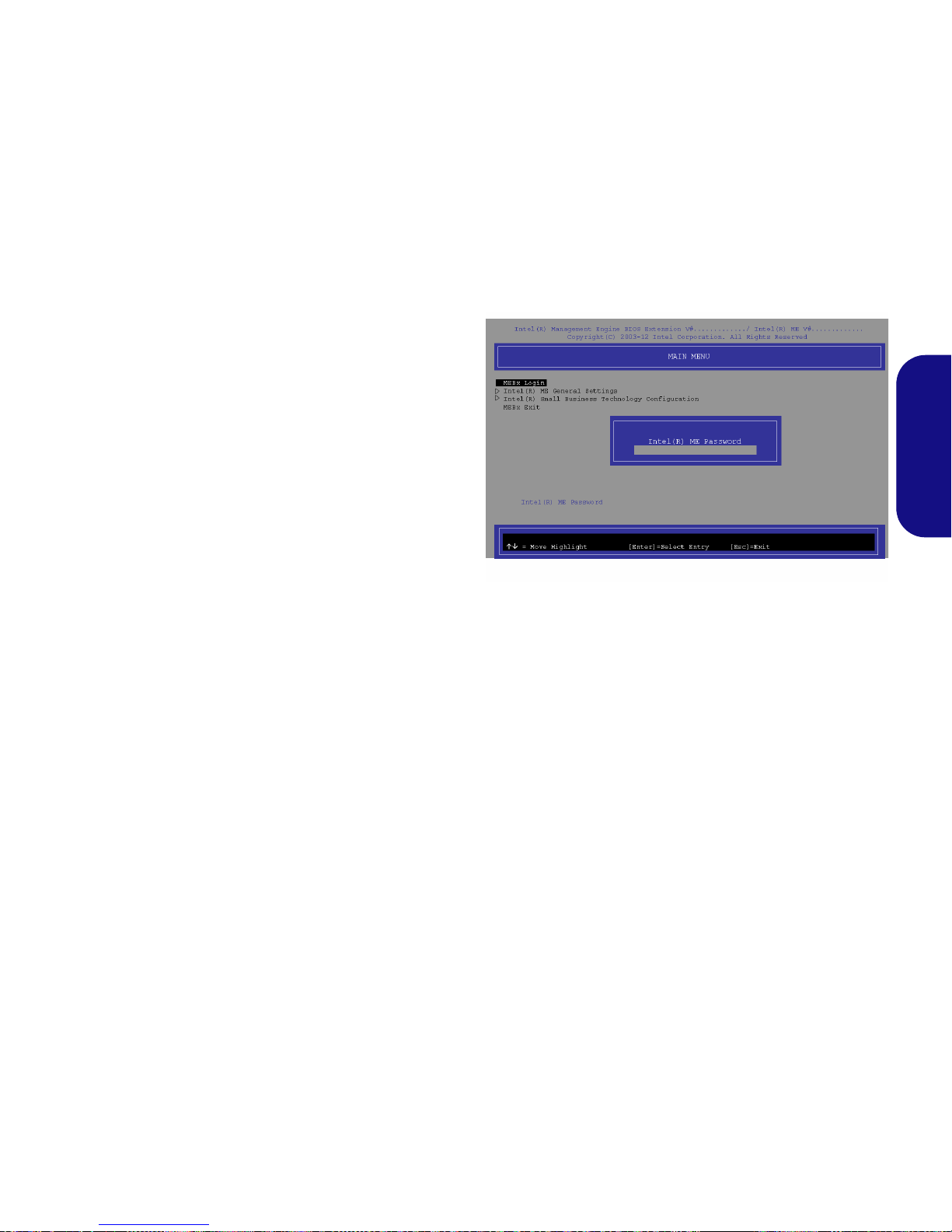
Accessing the Intel Management Engine
To access the Intel Management Engine press Ctrl + P
at startup. Your system administrator will need to assist
you in managing the information as applicable to your enterprise. Note the following password information for the
Intel Management Engine:
• The default password is “admin” (without quotes).
If you get an "Error - Intel(R) ME password change re-
jected" message when creating a new password, then note
the following parameters for creating a password:
• between 8 and 32 characters long
• Contain both upper and lower case Latin characters
• Have at least one numeric character
• Have at least one ASCII non-alphanumeric character (!,
@, #, $,%, ^, &, *)
Select MEBx Login and press “Enter” to access the password screen. Enter the password “admin” (without
quotes) and you will then be prompted to enter your own
password (note the password information above). Once
you have entered the password you will then be taken to
the platform configuration screen.
The platform configuration screen allows you to setup Intel ME as per your requirements (consult your IT administrator for the actual settings required).
Figure 13 - Intel(R) Management Engine
(Password Creation)

20
English
Troubleshooting
Problem Possible Cause - Solution
The Wireless LAN/Bluetooth/3G
modules cannot be detected.
The modules are off. Check the LED indicator and/or function key indicator to see if the
WLAN/Bluetooth/3G module is on or off (see Table 2 on page 6 and Table 3 on page 9). If
the LED indicator is off, then press the Fn + F11 (WLAN), Fn + F12 (Bluetooth) or Fn +
(3G) in order to enable the modules (see Table 3 on page 9).
The Bluetooth module is off after
resuming from Sleep.
The Bluetooth module’s default state will be off after resuming from the Sleep power-saving
state. Use the key combination (Fn + F12) to power on the Bluetooth module after the
computer resumes from Sleep.
The captured video files from the PC
Camera are taking up too much disk
space.
Note that capturing high resolution video files requ ires a su bstantial amount of disk space for
each file.
Note that the Windows system requires a minimum of 15GB of free space on the C: drive
system partition. It is recommended that you save the capture video file to a location other
than the C:drive, limit the file size of the captured video or reduce video resolution (Options
> Video Capture Pin... > Output Size).
The computer is off (or in Sleep
Mode) but powered by the AC/DC
adapter plugged in to a working
outlet or powered by the battery with
a capacity level above 20%. I have
plugged a device into the powered
USB port in order to charge it, but
the device is not charging.
The port is not powered on. Toggle power to the port using the Fn + power button
combination.
This function may not work with cert ai n e xte rn al USB comp li ant dev ices (check yo ur dev ice ’s
documentation). If this is the case, power the computer on and connect the external USB
device in order to charge it.
I previously turned off the WLAN
module using the Fn + F11 key
combination (or Windows Mobilty
Center button), but upon returning
to the machine the LED indicator
shows the WLAN module is ON.
The computer entered a power saving state with the WLAN Switch in the ON position, and
upon resuming from the power saving state the WLAN module turned ON. The position of
the WLAN switch governs the power status of the WLAN module at startup, and upon
resuming from a power saving state. This is the case even if you have previously turned the
module off using the Fn + F11 key combination or Windows Mobilty Center button prior to
the computer entering a power saving state.

21
English
Specifications
Latest Specification Information
The specifications listed in this here
are correct at the time of going to
press. Certain items (particularly
processor types/speeds) may be
changed, delayed or updated due to
the manufacturer's release schedule. Check with your service center
for details.
CPU
The CPU is not a user serviceable
part. Accessing the CPU in any way
may violate your warranty.
Processor Options
Model A:
Intel® Core™ i7 Processor
i7-3612QM (2.10GHz)
6MB L3 Cache, 22nm, DDR3-1600MHz,
TDP 35W
i7-3520M (2.90GHz)
4MB L3 Cache, 22nm, DDR3-1600MHz,
TDP 35W
Intel® Core™ i5 Processor
i5-3360M (2.80GHz), i5-3320M (2.60GHz),
i5-3210M (2.50GHz)
3MB L3 Cache, 22nm, DDR3-1600MHz,
TDP 35W
Intel® Core™ i3 Processor
i3-3110M (2.40GHz)
3MB L3 Cache, 22nm, DDR3-1600MHz,
TDP 35W
Intel® Core™ i7 Processor
i7-2640M (2.80GHz)
4MB L3 Cache, 32nm, DDR3-1333MHz,
TDP 35W
Intel® Core™ i5 Processor
i5-2540M (2.60GHz), i5-2520M (2.50GHz),
i5-2450M (2.50GHz), i5-2430M (2.40GHz)
3MB L3 Cache, 32nm, DDR3-1333MHz,
TDP 35W
Intel® Core™ i3 Processor
i3-2370M (2.40GHz), i3-2350M (2.30GHz),
3MB L3 Cache, 32nm, DDR3-1333MHz,
TDP 35W
Intel® Pentium™ Processor
B980 (2.40GHz), B970 (2.30GHz), B960
(2.20GHz), B950 (2.10GHz)
2MB L3 Cache, 32nm, DDR3-1333MHz,
TDP 35W
Model B:
Intel® Core™ i7 Processor
i7-3520M (2.90GHz)
4MB L3 Cache, 22nm, DDR3-1600MHz,
TDP 35W
Intel® Core™ i5 Processor
i5-3360M (2.80GHz), i5-3320M (2.60GHz)
3MB L3 Cache, 22nm, DDR3-1600MHz,
TDP 35W
LCD
15.6" (39.62cm) HD/ HD+
BIOS
AMI BIOS (One 64Mb SPI Flash ROM)
Core Logic
Model A:
Intel® HM77 Chipset
Model B:
Intel® QM77 Chipset
Memory
Two 204 Pin SO-DIMM Sockets Supporting
DDR3 1333/1600MHz Memory
Memory Expandable up to 8GB
(The real memory operating frequency
depends on the FSB of the processor.)

22
English
Video Adapter (Model A)
Intel Integrated GPU
(GPU is Dependent on Processor)
Intel® HD Graphics
Dynamic Frequency (Intel Dynamic Video
Memory Technology for up to 1.7GB)
Microsoft DirectX®10 Compatible
Intel® HD Graphics 3000
Dynamic Frequency (Intel Dynamic Video
Memory Technology for up to 1.7GB)
Microsoft DirectX®10 Compatible
Intel® HD Graphics 4000
Dynamic Frequency (Intel Dynamic Video
Memory Technology for up to 1.7GB)
Microsoft DirectX®11 Compatible
Video Adapter (Model B)
Intel® HD Graphics 4000
Dynamic Frequency (Intel Dynamic Video
Memory Technology for up to 1.7GB)
Microsoft DirectX®11 Compatible
Storage
(Factory Option) One Changeable
12.7mm(h) Optical Device Type Drive
(Super Multi Drive Module or Blu-Ray
Combo Drive Module)
One Changeable 2.5" 9.5mm (h) SATA
HDD
Audio
High Definition Audio Compliant Interface
2 * Built-In Speakers
Built-In Microphone
Security
BIOS Password
Security (Kensington® Type) Lock Slot
Fingerprint Reader
TPM v1.2
Intel vPro (Model B only)
Keyboard
Full-size “WinKey” keyboard (with numeric
keypad)
Pointing Device
Built-in T ouchpad (scrolling key functionality
integrated)
Communication
Built-In Gigabit Ethernet LAN
(Factory Option) 2M HD PC Camera Mod-
ule
(Factory Option) 3G Module (UMTS/HSPA
or UMTS/HSPA+)
WLAN/ Bluetooth Half Mini-Card
Modules:
Model A:
(Factory Option) Intel® Centrino® Wireless-N 2230 Wireless LAN (802.11b/g/n) +
Bluetooth 4.0
(Factory Option) Intel® Centrino® Wireless-N 135 Wireless LAN (802.11b/g/n) +
Bluetooth 4.0
(Factory Option) Third-Party Wireless LAN
(802.11b/g/n) + Bluetooth 4.0
(Factory Option) Third-Party Wireless LAN
(802.11b/g/n)
Model B:
(Factory Option) Intel® Centrino®
Advanced-N 6235 Wireless LAN (802.11a/
g/n) + Bluetooth 4.0
(Factory Option) Intel® Centrino®
Advanced-N 6205 Wireless LAN (802.11a/
g/n)

23
English
Interface
Three USB 3.0 Ports (Including one AC/DC
Powered USB port)
One USB 2.0 Port
One eSATA Port
One HDMI-Out Port
One Headphone-Out Jack
One Microphone-In Jack
One RJ-45 LAN Jack
One External Monitor Port
One ExpressCard/34(54) Slot
One DC-in Jack
One Docking Port
Card Reader
Embedded Multi-in-1 Push-Push Card
Reader
MMC (MultiMedia Card) / RS MMC
SD (Secure Digital) / Mini SD / SDHC/
SDXC
MS (Memory Stick) / MS Pro / MS Duo
Mini Card Slots
Slot 1 for WLAN Module or WLAN and
Bluetooth Combo Module
(Factory Option) Slot 2 for 3G Module
Environmental Spec
Temperature
Operating: 5
°C - 35°C
Non-Operating: -20°C - 60°C
Relative Humidity
Operating: 20% - 80%
Non-Operating: 10% - 90%
Power
Full Range AC/DC Adapter
AC Input: 100 - 240V, 50 - 60Hz
DC Output: 19V, 3.42A or 18.5V, 3.5A
(65W)
6 Cell Smart Lithium-Ion Battery Pack,
62.16WH
Dimensions & Weight
374mm (w) * 256mm (d) * 37.9mm (h)
2.5kg with ODD & 62.16WH Battery

24
English

25
Deutsch
Über das Ausführliche Benutzerhandbuch
Diese Kurzanleitung soll einen Überblick über die Schritte geben, die dazu notwendi g sind, das System zu starten. Dieses ist
nur eine Ergänzung und kein Ersatz für das erweiterte englischsprachige Benutzerhandbuch, das auf der mitgelieferten Disc
Device Drivers & Utilities + User's Manual im Adobe-Acrobat-Format vorliegt. Diese Disc enthält auch die Treiber und
Utility-Programme, die für einen einwandfreien Betrieb des Computers notwendig sind (Hinweis: Das Unternehmen behält
sich das Recht vor, diese Publikation ohne Vorankündigung zu überarbeiten und den Inhalt zu verändern).
Einige oder alle Funktionen des Computers sind bereits eingerichtet worden. Falls das nicht der Fall ist oder wenn Sie einzelne Teile des Systems neu konfigurieren (oder neu installieren) möchten, finden Sie eine Anleitung im erweiterten Benut-
zerhandbuch. Die Disc Device Drivers & Utilities + User's Manual enthält nicht das Betriebssystem.
Einhaltung gesetzlicher Vorschriften und Sicherheitshinweise
Beachten Sie sorgfältig die Hinweise zu gesetzlichen Vorschriften und zu Sicherheitshinweisen im erweiterten Benutzerhandbuch auf der Disc Device Drivers & Utilities + User's Manual.
© August 2012
Warenzeichen
Intel und Intel Core sind warenzeichen/e inget ra genes warenzeichen der Intel Corporation.

26
Deutsch
Hinweise zu Pflege und Betrieb
Das Notebook ist zwar sehr stabil, kann aber dennoch beschädigt werden. Damit es nicht dazu kommt, sollten Sie die
folgenden Hinweise beachten:
• Das Gerät darf nicht herunterfallen und in anderer Form Stößen
ausgesetzt werden. Wenn der Computer fällt, können das Gehäuse und
andere Komponenten beschädigt werden.
• Das Gerät darf nicht nass werden und sich nicht überhitzen. Compu-
ter und Netzteil dürfen nicht in der Nähe von Wärmequellen stehen oder
gelagert werden. Dies ist ein elektrisches Gerät. Wenn Wasser oder
andere Flüssigkeiten eindringen, kann der Computer stark beschädigt
werden.
• Vermeiden Sie Interferenzen mit anderen Geräten. Halten Sie den
Computer fern von magnetischen Feldern, die von Stromquellen, Monitoren, Magneten etc. erzeugt werden. Die können die Leistung beeinträchtigen und Ihre Daten beschädigen.
• Achten Sie auf die richtige Bedienung des Computers. Schalten Sie
ihn erst aus, wenn alle Programme geschlossen wurden (speichern Sie
Ihre Daten!). Speichern Sie regelmäßig Ihre Daten, da diese verloren
gehen können, wenn der Akku verbraucht ist.
Reparatur
Nehmen Sie vor dem Reinigen des Wenn Sie versuchen, de n
Computer selbst zu reparieren, können Ihre Garantieansprüche
verloren gehen. Außerdem besteht Stromschlaggefahr für Ihre
Gesundheit und das Gerät durch frei liegende Teile. Lassen Sie
Reparaturarbeiten nur von qualifizierten Reparaturfachleuten
durchführen, insbesondere wenn folgende Umstände vorliegen:
• Wenn das Netzkabel oder der AC/DC-Adapter beschädigt od er zers ch l is -
sen sind.
• Wenn der Computer Regen ausgesetzt war oder mit Flüssigkeiten in
Berührung gekommen ist.
• Wenn der Computer unter Beachtung der Bedienungsanweisungen nicht
korrekt arbeitet.
• Wenn der Computer heruntergefallen ist oder beschädigt wurde (berühren Sie nicht die giftige Flüssigkeit des LCD-Bildschirms).
• Wenn ein ungewöhnlicher Geruch, Hitze oder Rauch aus dem Computer
entweicht.
Sicherheitsinformationen
• Verwenden Sie nur einen AC/DC-Adapter, der für die Verwendung mit
diesem Computer zugelassen ist.
• Verwenden Sie nur das Netzkabel und die Akkus, die in diesem Benutzerhandbuch spezifiziert sind
. Entsorgen Sie die Akkus nicht in Feuer.
Sie können explodieren. Richten Sie sich nach den regional gültigen Entsorgungsvorschriften.
• Verwenden Sie den Akku nicht mehr , wenn er heruntergefallen ist oder in
anderer Weise beschädigt (z.B. verzogen) ist. Auch wenn der Computer
mit dem beschädigten Akku zu funktionieren schein, können dadurch
Stromkreise beschädigt werden, die schließlich einen Brand verursachen
können.
• Achten Sie darauf, dass Ihr Computer ausgeschaltet ist, wenn Sie es fur
den Transport z.B. wahrend einer Reise in eine Tasche einpakken.
• Nehmen Sie vor dem Reinigen des Computers den Akku heraus, und
trennen Sie es von allen externen Stromquellen, Peripheriegeräten und
Kabeln (einschließlich Telefonkabel) ab.
• Reinigen Sie den Computer mit einem weichen, sauberen Tuch. Tragen
Sie das Reinigungsmittel nicht direkt auf den Computer auf. Verwenden
Sie keine flüchtigen Reinigungsmittel (Petroleumdestillate) oder Scheuermittel zum Reinigen des Computers.
• Versuchen Sie nicht, Akkus zu reparieren. Lassen Sie die Akkupacks
durch den Servicevertreter oder qualifiziertes Fachpersonal reparieren
oder austauschen.
• Beachten Sie, dass das Logo bei den Computern, die über ein galvanisch
beschichtetes LCD-Logo verfügen, von einer Schutzfolie bedeckt ist.
Durch die natürliche Abnutzung kann diese Schutzfolie beschädigt werden oder abgehen und die scharfen Kanten des frei liegenden Logos
freigeben. Seien Sie in solch einem Fall vorsichtig bei der Handhabung
des Computers, und vermeiden Sie es, das herausstehende beschichtete
LCD-Logo zu berühren. Legen Sie keine Gegenstände in die Tragetasche, da diese während des Transports gegen den Computer drücken
können. Wenden Sie sich in einem solchen Fall von Abnutzung an Ihr
Service Center.

27
Deutsch
Polymer Akku Sicherheitshinweise
Beachten Sie die folgenden Hinweise, die sich speziell auf
Polymer Akkus beziehen. Diese Hinweise haben zudem Vorrang gegenüber den Allgemeinen Akku Sicherheitshinweisen.
• Polymer Akkus können sich etwas ausdehnen oder anschwellen. Dies ist
Teil des Sicherheitsmechanismus des Akkus und kein Anlass zur Sorge.
• Seien Sie vernünftig im Umgang mit Polymer Akkus. Verwenden Sie
keine Polymer Akkus in Umgebungen mit hohen Temperaturen und
lagern Sie keine ungenutzten Akkus über längere Zeiträume.
Entsorgen der Akkus/ Batterien & Achtung
Das von Ihnen gekaufte Produkt enthält einen au fladbaren Akku. Dier
Akku ist wiederverwertbar. Nach verschiedenen nationalen und
regionalen Getzgebungen kann es verboten in, einen nicht mehr
gebrauchsfähigen Akku in den normalen Hausmüll zu werfen. Informieren Sie sich bei Ihrem regionalen Entsorgungsunternehmen über
Recycling-Möglichkeiten oder korrekte Entsorgung.
Wenn ein falscher Akku eingesetzt wird, besteht Explosionsgefahr.
Tauschen Sie den Akku nur durch den gleichen oder einen
baugleichen Typ aus, der vom Hersteller emp fohlen wird. Entsorgen
Sie den verbrauchten Akku entsprechend d er Anweisungen des Her stellers.

28
Deutsch
Schnellstart
1. Entfernen Sie das gesamte Verpackungsmaterial.
2. Legen Sie den Computer auf eine stabile Unterlage.
3. Setzen Sie den Akku ein, und stellen Sie sicher, dass sie fest sitzt.
4. Schließen Sie alle Peripheriegeräte, die Sie mit dem Computer
verwenden wollen (z. B. Tastatur und Maus), an die
entsprechenden Schnittstellen an.
5. Schließen Sie den AC/DC-Adapter an die DC-Eingangsbuchse an
der linken Seite des Computers an. Verbinden Sie dann das
Netzkabel mit einer Netzsteckdose und dem AC/DC-Adapter.
6. Klappen Sie den Deckel/LCD vorsichtig mit einer Hand auf, und
öffnen Sie ihn auf einen angenehmen Sichtwinkel (jedoch nicht
weiter als 135°). Mit der anderen Hand halten Sie das Unterteil
des Computers fest (siehe Abb. 1) (Hinweis: Heben Sie den
Computer niemals am Deckel/LCD hoch).
7. Drücken Sie auf den Netzschalter, um den Computer
einzuschalten.
Systemsoftware
Möglicherweise wurde das Notebook bereits mit vorinstallierter Software ausgeliefert. Ist das nicht der Fall, oder
wenn Sie das Notebook für ein anderes System neu konfigurieren möchten, finden Sie dazu eine Anleitung in diesem
Handbuch zu Microsoft Windows 7.
Modellunterschiede
Diese Notebookserie umfasste zwei verschiedene Modelle
(Informationen finden Sie unter Technische Daten auf
Seite 45).
Abb. 1 - Öffnen des Deckels/LCD/Computers mit ange-
schlossenem AC/DC-Adapter
Herunterfahren
Bitte beachten Sie, daß
der Computer immer mit
dem Befehl Herunter-
fahren im Menü
Start
heruntergefahren werden muß.
Dadurch werden Festplatten- bzw. Systemprobleme vermieden.
135 ゚

29
Deutsch
Systemübersicht: Ansicht von vorne mit geöffnetem LCD-Bildschirm
Abb. 2
Ansicht von vorne mit ge-
öffnetem LCD-Bildschirm
1. PC-Kamera (optional)
2. LCD-Bildschirm
3. Netzschalter
4. LED-Anzeigen
5. Tastatur
6. Mikrofon
7. Touchpad mit Tasten
8. Fingerabdruckleser
7
Die Benutzung drahtlos
angeschlossener
Geräte in Flugzeugen
In der Regel ist die Benutzung jeglicher tragbarer
elektronischer Funkgeräte in Flugzeugen verboten. Achten Sie
darauf, daß die
Wireless-Module AUSGESCHALTET sind,
wenn Sie den Computer
im Flugzeug benutzen.
Drücken Sie die entsprechenden
Tastenkombinationen
(oder WLAN-Schalter
nur bei Wireless LAN),
um jeweils das 3G-, das
WLAN- oder das Bluetooth-Modul zu aktivieren. Prüfen Sie anhand
der LED-Anzeigen/visuellen Anzeigen, ob die
Module eingeschaltet
sind (siehe Tabelle 2 auf
Seite 30 und Tabelle 3
auf Seite 33).
Beachten Sie, dass der Funktionsbereich
des Touchpads und der Tasten innerhalb
der rot gepunkteten Linien liegt.
2
4
1
3
5
6
8
7

30
Deutsch
LED-Anzeigen
Die LED-Anzeigen auf dem Computer zeigen wichtige
Informationen über den aktuellen Status des Computers.
Tabelle 1 - LED-Statusanzeigen
Tabelle 2 - LED-Stromanzeigen
Symbol Farbe Beschreibung
Grün Es wird auf die Festplatte zugegriffen
Grün
Die Funktion NumLk (Nummernta-
statur) ist aktiviert
Grün Caps-Lock ist aktiviert
Grün Scroll-Lock ist aktiviert
Symbol Farbe Beschreibung
Grün Das WLAN-Modul ist eingeschaltet
Orange Das Bluetooth-Modul ist eingeschaltet
Orange Der AC/ DC-Adap ter i st ang eschl ossen
Lampe
blinkt
Orange
Der eingeschaltete USB Anschluss ist
eingeschaltet
(siehe Seite 32)
Grün Der Computer ist angeschaltet
Lampe
blinkt
grün
Das System ist im konfigurierten
Energiesparmodus
Orange Der Akku wird geladen
Grün Der Akku ist voll geladen
Lampe
blinkt
orange
Der Akku hat einen kritisch niedrigen
Stromstatus erreicht

31
Deutsch
Systemübersicht: Ansicht von vorne, hinten, unten & oben
Docking
Wenn Ihr Kauf die Dockingstation enthält, öffnen Sie den Riegel des Dockinganschlussfachs
und richten Sie den Computer am Platzhalter der Dockingstation aus (eine ausführliche Beschreibung des Dockingvorgangs finden Sie im Begleitheft zur Dockingstation).
Vorderseite
Hinterseite
Abb. 3
Ansicht von vorne, hinten,
unten & oben
1. LED-Anzeigen
2. WLAN-Schalter
3. SicherheitsschloßBuchse
4. Akku
5. Docking-Anschluss
6. Luftungsoffnung
7. Komponentenfachabdekkung
8. Abdeckung des Festplattenschachts
9. Lautsprecher
10. Dockingstation (optional)
WLAN-Schalter
Schalten Sie das WLANModul mit dem WLANSchalter (nur bei Wireless
LAN) ein oder aus. Die
Position des WLANSchalters bestimmt den
Betriebsstatus des
WLAN-Moduls beim Systemstart und beim
Wiederherstellen aus
einem Stromsparstatus.
3
12
4
5
4
7
6
8
9
9
6
6
10

32
Deutsch
Systemübersicht: Ansicht von links und rechts
Abb. 4
Ansicht von links und
rechts
1. DC-Eingangsbuchse
2. Schnittstelle für externen Monitor
3. RJ-45 LAN-Buchse
4. eSATA-Anschluss
5. Luftungsoffnung
6. Eingeschaltet e USB
3.0 Anschluss
7. 2 USB 3.0 Anschlüsse
8. HDMI-Ausgangsanschluss
9. ExpressCard/54(34)Steckplatz
10. Multi-in-1 Kartenleser
11. Mikrofon-Eingangsbuchse
12. Kopfhörer-Ausgangsbuchse
13. USB 2.0 Anschluss
14. Schacht für optisches
Laufwerk
15. Notauswurfloch
Bottom
Dockinganschlussfach
Wenn im Lieferumfang die Dockingstation enthalten, aber der Computer nicht an die Dokkingstation angeschlossen ist, muss der
Deckel geschlossen bleiben. Auf diese Weise
wird vermieden, dass Fremdkörper und/oder
Staub in den Kontaktbereich gelangen. Wenn
die Kaufoption die Dockingstation nicht enthält,
verhindert ein spezieller Einsatz das versehentliche Öffnen des Dockingangschlusses.
Versuchen Sie nicht, die Abdeckung zu öffnen
oder den Einsatz zu entfernen.
Überhitzung
Zum Schutz vor Überhitzung Ihres Computers
dürfen die Luftungsoffnung(en) nicht während
das Notebook in Betrieb ist verdeckt werden.
Linke Seite
Rechte Seite
USB
Die USB 3.0 Anschlüsse sind blau. Die Datenübertragung ist bei USB 3.0 viel schneller
als bei USB 2.0, und USB 3.0 ist rückwärts
kompatibel mit USB 2.0. Wenn der eingeschaltete USB 3.0 Anschluss eingeschal-
tet ist, kann er andere Geräte auch bei
ausgeschaltetem System mit Strom versorgen
(jedoch nur zum Aufladen, nicht für den
Betrieb der Geräte), sofern das System mit
dem AC/DC-Adapter mit dem Stromnetz verbunden oder über einen Akku mit mehr als 20
% Ladung mit Strom versorgt wird (die Stromversorgung kann bei bestimmten Geräten u.
U. nicht funktionieren - siehe Seite 44). Dieser Anschluss wird mit der Tastenkombination Fn + Netzschalter eingeschaltet.
6
1
8
9
3
5
2
4
6 7
7
12
13
14
15
11
10

33
Deutsch
Tastatur & Funktionstasten
Die Tastatur hat eine eingebettete Nummerntastatur für
einfache Zahleneingabe. Durch Drücken auf Num wird die
Nummerntastatur ein- und ausgeschaltet. Zusätzlich gibt es
Funktionstasten, über die Sie direkt zwischen den Funktionen
umschalten können. Wenn die Funktionstasten (F1 - F12)
gleichzeitig mit der Fn-Taste gedrückt werden, funktionieren
sie wie Hotkeys. Neben den Tastenkombinationen für die
Grundfunktionen gibt es visuelle Anzeigen, wenn der Hotkey
Treiber installiert ist.
Tasten Funktion/Visuelle Anzeigen Tasten Funktion/Visuelle Anzeigen
Fn + ~ Wiedergabe/Pause (in Audio /Videoprogrammen) Fn + F10
PC-Kamera
aktivieren/deaktivieren
Fn +
3G-Modul aktivieren/deaktivieren Fn + F11
Wireless-LAN-Modul
aktivieren/deaktivieren
Fn + F1
Touchpad
aktivieren/deaktivieren
Fn + F12
Bluetooth-Modul
aktivieren/deaktivieren
Fn + F2
LCD-Hintergrundlicht ausschalten (zum Einschalten
beliebige Taste drücken oder Touchpad berühren)
Fn + Num
Ein-/Ausschalten der
Nummerntastatur
Fn + F3
Stummschaltung/Stummschal-
tung aufheben
Fn + Rollen
Ein-/Ausschalten des
Scroll-Modus
Fn + F4 Wechsel Schlaf/Wiederaufnahme
Ein-/Ausschalten der
Feststelltaste
Fn + F5/F6
Audio-Lautstärke
verringern/erhöhen
Fn +
Netzschalter
Ein-/Ausschalten des eingeschalteten USB
Anschlusses (siehe Seite 32)
Fn + F7 Wechseln der Anzeigegerate Fn + Esc
Ein-/Ausschalten des Control Center (Steuerzent-
rum) (siehe Seite 34)
Fn + F8/F9
LCD-Helligkeit verringern/erhö-
hen
Tabelle 3 - Funktionstasten & visuelle Anzeigen
Numeric
Abb. 5 - Tastatur
Fn Taste
Ein-/Ausschalten des
3G-Moduls
Funktionstasten
Num &
Rollen
Nummemtastatur

34
Deutsch
Control Center (Steuerzentrum)
Drücken Sie auf die Tastenkombination Fn + Esc, um das Control Center (Steuerzentrum) ein-/auszuschalten. Das Control
Center (Steuerzentrum) bietet den schnellen Zugriff auf häufig verwendete Funktionen, und Sie haben hier die Möglichkeit,
Module direkt ein-/auszuschalten.
Abb. 6 - Control Center
Klicken Sie auf eine beliebige Taste, um ein Modul (z. B. Touchpad, Kamera) ein-/auszuschalten. Klicken Sie auf Power
Conservation (Strom sparen), um einen der Modi Performance (Leistung), Balanced (Ausgeglichen) oder Energy Star
auszuwählen. Klicken Sie auf die Tasten (oder drücken Sie nur auf die Maustaste, und halten Sie diese gedrückt), um die
Helligkeit/Lautstärke (Brightness/Volume) einzustellen. Klicken Sie auf Display Switch (Anzeige wechseln)/Time Zone
(Zeitzone)/Desktop Background (Desktop-Hintergrund), um das entsprechende Windows-Systemsteuerungsfenster aufzurufen. Klicken Sie auf den Sleep (Schalter) für den Ruhezustand, um den Computer in den Ruhezustand oder in einen Ener-
giesparmodus zu versetzen.
Die WLAN- und
Bluetooth-Module
Abtrennen
Klicken Sie auf die Taste
Dokking, um das System bei
laufendem Gerät abzutrennen
(wenn Ihr Computer diese Funktion unterstützt). Wenn das System erfolgreich abgeschlossen
wurde, erscheint in der Taskleiste
die Meldung Undock Complete
(Abdocken abgeschlossen).
sind aus

35
Deutsch
Energiemodi
Sie können einen Energiemodus einstellen, indem Sie im Control Center auf das entsprechende Symbol klicken. Jeder
Energiemodus wirkt sich auf den Stromstatus der Module (z. B. WLAN, Bluetooth, 3G oder Kamera), die Bildschirmhelligkeit, die Stromversorgung des TouchPads und den Lautlos-Modus aus. Klicken Sie auf das Control Center-Symbol,
um einen allgemein gültigen Energiemodus einzustellen. Klicken Sie dann auf die einzelnen Symbole des Control Centers,
um die Module ein-/auszuschalten.
In Tabelle 4 finden Sie die Grundeinstellungen für jeden Energiemodus.Wenn Sie die Option User Defined (Benutzerdefiniert) wählen, werden die von Ihnen konfigurierten Einstellungen angezeigt.
Tabelle 4 - Energiemodus
Modi
Power Saving
(Stromsparmodus)
Flight
(Flugmodus)
Entertainment
(Unterhaltungsmodus)
Quiet
(Lautlosmodus)
Performance
(Leistungsmodus)
User Defined
(Benutzerdefiniert)
Symbol
Energiesparplan Energiesparmodus Ausbalanciert Energiesparmodus
Energiesparmo-
dus
Höchstleistung
Benutzerdefiniert
Power Conservation Mode
(Stromsparmodus)
Energy Star BIOS-Standard Energy Star Energy Star
Performance (Leis-
tung)
Brightness
(Helligkeits)
14 42 100 42 100
WLAN AUS AUS AN AN AN
3G AUS AUS AUS AUS AUS
PC-Kamera AUS AUS AUS AN AN
Touchpad AN AN AN AN AN

36
Deutsch
Power Status (Energiestatus)
Das Energiestatus-Symbol zeigt an, ob die Stromversorgung aktuell über den Akku oder über das an das Stromnetz angeschlossene Netzteil erfolgt. Die Energiestatus-Anzeige zeigt den aktuellen Akkuladestatus an.
Brightness (Helligkeits)
Das Helligkeits-Symbol zeigt die aktuell ei ngestellt e Bildschirmhelligkeit an. Sie können die Bildschirmhelli gkeit entweder
mit dem Schieberegler oder mit der Tastenkombination Fn + F8/F9 ändern. Mit der Tastenkombination Fn + F2 wird das
LED-Hintergrundlicht ausgeschaltet (drücken Sie auf eine beliebige Taste, um es wieder einzuschalten). Beachten Sie, dass
die Bildschirmhelligkeit auch vom eingestellten Energiemodus abhängt.
Volume (Lautstärke)
Das Lautstärke-Symbol zeigt die aktuelle Lautstärke an. Sie können die Lautstärke entweder mit dem Schieberegler oder
mit der Tastenkombination Fn + F5/F6 einstellen. Mit der Tastenkombination Fn + F3 wird der Ton ausgeschaltet.
Power Conservation (Strom sparen)
Dieses System unterstützt die Energy Star-Stromsparfunktionen, die Computer (CPU, Festplatte usw.) nach einer längeren
Zeit der Inaktivität in einen Ruhemodus versetzen, bei dem weniger Strom verbraucht wird. Klicken Sie entweder auf die
Taste Performance, Balanced oder Energy Star.
Sleep (Schalter)
Klicken Sie auf den Schalter für den Ruhezustand, um die Schaltflächen Ruhezustand oder Schlaf aufzurufen.
Klicken Sie dann auf eine der beiden Tasten, um den Computer in den jeweiligen Modus zu versetzen.

37
Deutsch
Display Switch (Anzeige wechseln) ,
Klicken Sie auf die Taste zum Wechseln des Anzeigegeräts, um das Menü aufzurufen (Sie können dazu auch die
Tastenkombination + P verwenden), und wählen Sie einen Anzeigemodus aus.
Time Zone (Zeitzone)
Wenn Sie auf die Schaltfläche Zeitzone klicken, wird das Windows-Systemsteuerungsfenster Datum und Uhrzeit aufgerufen.
Desktop Background (Desktop-Hintergrund)
Wenn Sie auf die Schaltfläche Desktop-Hintergrund klicken, können Sie das Bild für den Desktophintergrund einstellen.
TouchPad/PC-Kamera/Wireless-LAN-Modul/Bluetooth-Modul/3G-Modul
Klicken Sie auf eine dieser Tasten, um das TouchPad ein- oder auszuschalten. Ist es ausgeschaltet, erscheint links oben am
Symbol
ein Kreuz. Beachten Sie, dass sowohl der Energiemodus eines Moduls und des TouchPads auch vom aus-
gewählten Energiemodus abhängen.
Docking
Klicken Sie auf die Schaltfläche Docking, um das System für das Anschließen/Abtrennen eines Geräts vorzubereiten.
Caps Lock/Scroll Lock/ Number Lock
Klicken Sie auf die Taste, um den gewünschten Feststellmodus auszuwählen.

38
Deutsch
3G-Modul
Wenn Ihr Modell das optionale 3G-Modul enthält, folgen
Sie den nachfolgenden Anweisungen, um die USIM-Karte
zu installieren (Sie erhalten sie von Ihrem Dienstanbieter).
Installieren Sie dann die Anwendung.
Einsetzen der USIM-Karte
1. Schalten Sie den Comp ute r aus, drehen Sie es herum, und
nehmen Sie den Akku heraus (schieben Sie die Riegel in
die unten angezeigte Richtung, und ziehen Sie den Akku heraus).
Abb. 7 - Abnehmen des Akkus
2. Schieben Sie die USIM-Karte wie unten abgebildet hinein, und
lassen Sie sie einrasten. Setzen Sie den Akku wieder ein
.
Abb. 8 - Einsetzen der USIM-Karte
1
1
Ausrichtung der USIM-Karte
Die lesbare Seite der USIM-Karte (die Seite,
auf der sich die Goldkontakte befinden)
muss wie abgebildet nach oben zeigen.

39
Deutsch
Installation der Treiber
Die Disc Device Drivers & Utilities + User's Manual enthält die Treiber und Hilfspro-
gramme, die für das einwandfreie Funktionieren des Computers notwendig sind. Möglicherweise wurden diese bereits vorinstalliert. Ist das nicht der Fall, legen Sie die Disc ein, und
klicken Sie auf Install Drivers (Schaltfläche) oder Option Drivers (Schaltfläche), um das
Treibermenü Optional aufzurufen.
Installieren Sie die Treiber in der in Abb. 9 angegebenen
Reihenfolge. Markieren Sie die Treiber, die installiert werden soll en (notieren Si e zum späteren Nachlesen die Treiber, die Sie installiert haben). Hinweis: Muss ein Treiber neu installiert
werden, sollten Sie den alten Treiber zunächst deinstallieren.
Manuelle Treiber-Installation
Klicken Sie in der Anwendung Drivers Installer auf die Schaltfläche Browse CD/DVD und
navigieren Sie zu der ausführbaren Datei in dem Ordner für Ihren Treiber.
Wenn während des Installationsvorgangs das Fenster Neue Hardware gefunden erscheint,
klicken Sie auf Abbrechen, um das Fenster zu schließen. Befolgen Sie dann die Installationsanweisungen.
Allgemeine Hinweise zur
Treiberinstallation
Wenn Sie keine fortgeschrittenen Kenntnisse
haben, folgen Sie für jeden
Treiber den Anweisungen
auf dem Bildschirm (z. B.
Weiter > Weiter > Fertig
stellen). In vielen Fällen
ist es erforderlich, den
Computer nach der
Treiberinstallation neu zu
starten.
Alle Module (z. B. PCKamera, WLAN oder 3G)
müssen vor der Treiberinstallation eingeschaltet
werden.
Windows Update
Nachdem Sie alle Treiber
installiert haben, sollten
Sie die Funktion Windows
Update aktualisieren, um
immer die neuesten Sicherheits-Updates usw. zu
erhalten (die Updates enthalten die neuesten
Fehlerbehebungen von
Microsoft).
Treiberinstallation und Stromversorgung
Während die Treiber installiert werden, muss der
Computer über den AC/DC-Adapter mit Strom versorgt werden. Einige Treiber benötigen für den Installationsvorgang sehr viel Strom. Wenn der Akku
nicht mehr über genügend Strom verfügt, kann sich
das System während der Installation ausschalten,
was zu Systemfehlern führen kann (das ist kein Sicherheitsproblem, und der Akku ist innerhalb von
einer Minute wieder aufladbar).
Abb. 9 - Installation der Treiber

40
Deutsch
Fingerabdruckleser
Melden Sie Ihre Fingerabdrücke vor dem Benutzen wie unten beschrieben an.
Benutzerregistrierung
1. Klicken Sie auf Start > Programme/ Alle Programme > Protector Suite QL > Benutzerregistrierung, oder doppelKlikken
Sie in der Taskleiste auf das Symbol .
2. Wenn das Programm das erste mal gestartet wird , müssen Sie
auf die Schaltfläche Annehmen klicken, um die Lizenz zu
akzeptieren.
3. Wenn Sie kein Windows-Kennwort e ingerichtet haben, werden
Sie dazu aufgefordert (Hinweis: Wenn kein Kennwort festgelegt
wurde, kann Protector Suite QL nicht den Zugriff auf den
Computer sichern).
4. Wenn Sie das Kennwort eingegeben haben, klicken Sie auf
Senden.
5. Sie werden dann aufgefordert, Ihre Fingerabdrücke zu
registrieren (bei Tutorial erhalten Sie jederzeit Hilfe zum
Registrieren Ihrer Fingerabdrücke).
6. Klicken Sie auf eine der Tasten über einem beliebigen Finger, um
mit der Registrierung dieses Fingers zu beginnen.
7. Führen Sie den Finger zum Registrieren des Abdrucks so lange
über den Sensor, bis der Fortschrittsbalken 100% erreicht hat.
8. Wiederholen Sie diesen Vorgang für alle Finger, die registriert
werden sollen, und dann klicken Sie auf Speichern und
fortfahren.
9. Geben Sie ein Sicherungskennwort ein, und klicken Sie auf
Anwenden.
10. Schließen Sie das Statusfenster.
11. Weitere Informationen erhalten Sie auch, wenn Sie das Tutorial
oder die Produkt-Tour ausführen, bei denen das Video mit der
Produkt-Tour gestartet wird.
12. Klicken Sie mit der rechten Maustaste auf das
Taskleistensymbol , um das Control Center zu starten. Dort
können Sie Fingerabdrücke bearbeiten, Anwendungen
registrieren, auf das Hilfe-Menü zugreifen usw.
13. Wenn Sie mit dem Finger auf den Fingerabdruckleser tippen,
können Sie auf das Biomenü zugreifen, um den Computer zu
sperren, Websites zu registrieren, auf den Personal Safe oder
E-Wallet zugreifen, das Control Center zu öffnen und das Hilfe-
Menü aufzurufen.
Abb. 10 - Control Center & Biomenü
Fingerabdruckregistrierung
Beachten Sie, dass es für den
Fall einer Verletzung o. ä. sinnvoll ist, mehr als einen Finger
zu registrieren.

41
Deutsch
TPM (Trusted Platform Module)
Bevor Sie die TPM-Funktionen einrichten, müssen Sie die
Sicherheitsplattform initialisieren.
Aktivieren der TPM-Funktionen
1. Starten Sie das Notebook neu.
2. Rufen Sie das Aptio Setup Utility auf, indem Sie während des
POST-Vorgangs auf F2 drücken.
3. Wählen Sie mit den Pfeiltasten das Menü
Security.
4. Wählen Sie TPM Configuration und drücken Sie auf die
Eingabetaste.
5. Wählen Sie TPM Support und drücken Sie auf die Eingabetaste.
Wählen Sie Enable und drücken Sie auf die Eingabetaste.
6. Wählen Sie TPM State, drücken Sie auf die Eingabetaste und
wählen Sie Enable (Aktivieren), um den TPM Status auf Aktiviert
zu setzen. Sie müssen anschließend auf F4 drücken, um die
Änderungen zu speichern und den Computer neu zu starten.
7. Drücken Sie beim Neustart des Computers auf F2, um das BIOS
erneut aufzurufen und gehen Sie zum Menü TPM Configuration.
8. Wählen Sie Pending TPM operation (Laufende TPM Operation),
drücken Sie auf die Eingabetaste und wählen Sie die benötigte
Option aus (wenn Sie TPM initialisieren, sollten Sie Enable Take
Ownership (Besitz übernehmen aktivieren) auswählen). Sie
müssen anschließend auf F4 drücken, um die Änderungen zu
speichern und den Computer neu zu starten.
9. Sie können jetzt den TPM Treiber installieren und anschließend
den TPM initialisieren.
Installieren des TPM-Treibers
1. Klicken Sie auf Option Drivers (Schaltfläche).
2. Klicken Sie auf 7.Install TPM Driver > Ja.
3. Klicken Sie auf Installieren > Weiter.
4. Klicken Sie auf die Schaltfläche, um die
Lizenzvereinbarung anzunehmen und klicken Sie dann auf
Weiter.
5. Klicken Sie auf Weiter > Weiter >Installieren.
6. Klicken Sie auf Fertig stellen > Ja, um den Computer neu
zu starten.
Initialisieren des TPM
1. Die Software des TPM wird über den Eintrag Infineon Security
Platform Lösung > Security Platform verwalten im Menü Start
> Programme/Alle Programme gestartet.
2. Klicken Sie auf Benutzereinstellungen, und dann auf Ja, oder
klicken Sie mit der rechten Maustaste auf das Symbol im
Benachrichtigungsbereich der T askleiste und wählen Sie Security
Platform-Initialisierung (oder klicken Sie auf die Sprechblase
des Security Platform-Status in der Taskleiste).
3. Die Schnelle Initialisierung Methode wird automatisch für Sie
ausgewählt (falls Sie die erweiterten Einstellungen Ihres
Netzwerkadministrators verwenden müssen, wählen Sie
Erweiterte Initialisierung).
4. Sie müssen einen Wechseldatenträger (z.B. ein USB FlashLaufwerk) zum Speichern von Kennwörtern und Daten verwenden
(bewahren Sie das Medium an einem sicheren Ort auf, bevor Sie
es benötigen).

42
Deutsch
5. Wählen Sie das zu benutzende Laufwerk aus der Liste aus und
klicken Sie auf Weiter.
6. Wählen Sie die gewünschten Funktionen der Security Platform
durch Anklicken der entsprechenden Kästchen aus.
7. Geben Sie ein Basic User Password (Benutzerkennwort) ein
(und ein zweites Mal zur Bestätigung) und klicken Sie auf Weiter.
8. Klicken Sie auf Weiter, um die Einstellungen zu bestätigen.
9. Der Computer wird die Einstellungen anschließend initialisieren.
10. Klicken Sie auf Fertig stellen.
11. Klicken Sie auf die Registerkarten und Fenster, um die
Einstellungen anzupassen.
12. Klicken Sie doppelt auf das Taskleisten-Symbol zum Aufruf
des Parametrierungstools der Infineon Security Platform oder
klicken Sie mit der rechten Maustaste auf das Taskleisten-Symbol
und wählen eine Menüoption.
Parametrierungstool der Infineon Security Platform
Mit dem Parametrierungstool der Infineon Security Platform
können Sie den TPM Status verwalten und überprüfen, Ihre
Kennwortinformationen verwalten und Ihre TPM Daten sichern und wiederherstellen. Da ein TPM normalerweise in
großen Unternehmen und Organisationen verwaltet wird, benötigen Sie bei der Verwaltung der hiesigen Informationen
die Hilfe Ihres Systemadministrators.
Abb. 11
Assistent
für die
schnelle Ini-
tialisierung
der Security
Platform
Abb. 12 - Parametrierungstool der Infineon
Security Platform

43
Deutsch
Intel® vPro™ Technology
Intel® vPro™ Technology wird nur von Modell B Computern unterstützt. Die auf dem Mainboard des Computers integrierten technischen Funktionen ermöglichen es ITAbteilungen aus der Ferne auf den Computer zuzugreifen.
IT-Abteilungen können Computer somit unabhängig vom
Zustand des Betriebssystems oder dem Energiestatus des
Computers überwachen, warten und verwalten. Dies kann
über eine Kabel- oder WLAN-Verbindung in einem Firmennetzwerk geschehen, oder selbst außerhalb der FirmenFirewall über eine kabelgebundene LAN-Verbindung.
Zugriff auf die Intel Management Engine
Drücken Sie für den Zugriff auf die Intel Management
Engine beim Start auf Strg + P. Ihr Systemadministrator
wird Ihnen beim Verwalten der für das Unternehmen benötigten Informationen helfen. Beachten Sie die folgenden
Kennwortinformationen für die Intel Management Engine:
• Das Standardpasswort ist „admin“ (ohne Anführungszeichen).
Falls die Meldung „Fehler - Intel(R) ME Kennwortänderung
abgelehnt“ beim Erstellen eines neuen Kennwortes erscheint, beachten Sie die folgenden Regeln für die Erstellung
eines neues Kennwortes:
• zwischen 8 und 32 Zeichen lang
• Enthält sowohl Groß- als auch Kleinbuchstaben
• Enthält mindestens eine Zahl
• Enthält mindestens ein nicht-numerisches ASCII Zeichen (!,
@, #, $,%, ^, &, *)
Wählen Sie MEBx Login (MEBx Anmeldung) und drücken
Sie auf “Enter”, um das Passwortfenster aufzurufen. Geben
Sie das Passwort “admin” (ohne Anführungszeichen), woraufhin Sie zur Eingabe Ihres eigenen Passwortes
aufgefordert werden (beachten Sie die obigen Informationen
zum Passwort). Nach Eingabe des Kennwortes erscheint der
Plattform-Konfigurationsbildschirm.
Im Plattform-Konfigurationsbildschirm können Sie Intel ME
Ihren Wünschen nach einstellen (wenden Sie sich für die benötigten Einstellungen an Ihren IT-Administrator).
Abb. 13 - Intel(R) Management Engine
(Kennworterstellung)

44
Deutsch
Fehlerbehebung
Problem Mögliche Ursache - Lösung
Die Module Wireless-LAN/Bluetooth/3G
können nicht erkannt werden.
Das/Die Modul(e) ist/sind ausgeschaltet. Prüfen Sie anhand der LED-Anzeige und/
oder Funktionstastenanzeige, ob das WLAN/Bluetooth/3G-Modul ein- oder
ausgeschaltet ist (si e he Tabelle 2 auf Seite 30 und Tabelle 3 auf Seite 33). Wenn die
Anzeige-LED nicht leuchtet, drücken Sie die Tastenkombination Fn + F11 (WLAN), Fn
+ F12 (Bluetooth) oder Fn + (3G), um das/die Modul(e) zu aktivieren (siehe
Tabelle 3 auf Seite 33).
Das Bluetooth-Modul ist aus, wenn das Gerät
aus dem Energiesparmodus zurückkehrt.
Das Bluetooth-Modul ist standardmäßig ausgeschaltet, wenn es aus dem
Energiesparmodus zurückkehrt. Drücken Sie die Tastenkombination (Fn + F12), um das
Bluetooth-Modul nach der Rückkehr aus dem Energiesparmodus wieder einzuschalten.
Die mit der PC-Kamera aufgenommenen
Dateien benötigen zu viel Speicherplatz.
Videodateien, die mit hoher Auflösung aufgenommen werden, erfordern sehr viel
Speicherplatz.
Beachten Sie, dass das Betriebssystem Windows mindestens 15GB freien Speicher
im Laufwerk C: der Systempartition benötigt. Es wird empfohlen, die aufgenommenen
Videodateien in einem anderen Laufwerk als C: zu speichern, die Dateigröße der
Aufnahmedateien zu beschränken oder die Auflösung der Videos zu verringern
(Optionen/Options > Video Aufnahme konfigurieren.../Video Capture Pin... >
Ausgabegröße).
Der Computer ist ausgeschaltet (oder im
Energiesparmodus), wird aber über den an das
Stromnetz angeschlossenen AC/DC-Adpater
mit Strom versorgt oder über einen Akku mit
mehr als 20 % Ladung mit Strom versorgt wird.
Ich habe ein Gerät an den eingeschalteten
USB Anschluss angeschlossen, um es
aufzuladen, was aber nicht geschieht.
Der Anschluss ist nicht eingeschaltet. Schalten Sie den Anschluss mit der
Tastenkombination Fn + Netzschalter ein.
Bei manchen externen USB-Geräten funktioniert die Stromversorgung nicht (lesen Sie
dazu in der Dokumentation zum Gerät nach). Ist das der Fall, schließen Sie das
externe USB-Gerät an, und laden Sie es bei eingeschaltetem Computer auf.
Ich habe das WLAN-Modul mit der
Tastenkombination Fn + F11 (oder mit der
Windows-Mobilitätscenter-Taste)
ausgeschaltet, aber die LED-Anzeige zeigt
an, dass das WLAN-Modul weiterhin
eingeschaltet ist.
Der Computer hatte mit eingeschaltetem WLAN-Schalter in einen Stromsparstatus
gewechselt. Beim wiederherstellen aus dem Stromsparstatus ist das WLAN-Modul
weiterhin eingeschaltet. Die Position des WLAN-Schalters bestimmt den Betriebsstatus
des WLAN-Moduls beim Systemstart und beim Wiederherstellen aus einem
Stromsparstatus. Das ist auch dann der Fall, wenn Sie das Modul mit der
Tastenkombination Fn + F11 oder der Windows-Mobilitätscenter
-Taste ausschalten,
b
evor der Computer in einen Stromsparmodus wechselt.

45
Deutsch
Technische Daten
Aktualität der technischen Daten
Die in diesem Teil aufgeführten technischen Daten sind zum Zeitpunkt der
Druckstellung richtig. Bestimmte
Elemente (insbesondere Prozessortypen/-geschwindigkeiten) können im
Rahmen des Entwicklungsplans des
Herstellers zwischenzeitlich geändert
oder aktualisiert werden. Detailinformationen erhalten Sie bei Ihrem Servicezentrum.
CPU
Die CPU darf nicht vom Anwender
repariert werden. Jeglicher Zugriff auf
die CPU führt zum Verlust der Garantieansprüche.
Prozessor-Optionen
Modell A:
Intel® Core™ i7 Prozessor
i7-3612QM (2,10GHz)
6MB L3 Cache, 22nm, DDR3-1600MHz,
TDP 35W
i7-3520M (2,90GHz)
4MB L3 Cache, 22nm, DDR3-1600MHz,
TDP 35W
Intel® Core™ i5 Prozessor
i5-3360M (2,80GHz), i5-3320M (2,60GHz),
i5-3210M (2,50GHz)
3MB L3 Cache, 22nm, DDR3-1600MHz,
TDP 35W
Intel® Core™ i3 Prozessor
i3-3110M (2,40GHz)
3MB L3 Cache, 22nm, DDR3-1600MHz,
TDP 35W
Intel® Core™ i7 Prozessor
i7-2640M (2,80GHz)
4MB L3 Cache, 32nm, DDR3-1333MHz,
TDP 35W
Intel® Core™ i5 Prozessor
i5-2540M (2,60GHz), i5-2520M (2,50GHz),
i5-2450M (2,50GHz), i5-2430M (2,40GHz)
3MB L3 Cache, 32nm, DDR3-1333MHz,
TDP 35W
Intel® Core™ i3 Prozessor
i3-2370M (2,40GHz), i3-2350M (2,30GHz)
3MB L3 Cache, 32nm, DDR3-1333MHz,
TDP 35W
Intel® Pentium™ Prozessor
B980 (2,40GHz), B970 (2,30GHz), B960
(2,20GHz), B950 (2,10GHz)
2MB L3 Cache, 32nm, DDR3-1333MHz,
TDP 35W
Modell B:
Intel® Core™ i7 Prozessor
i7-3520M (2,90GHz)
4MB L3 Cache, 22nm, DDR3-1600MHz,
TDP 35W
Intel® Core™ i5 Prozessor
i5-3360M (2,80GHz), i5-3320M (2,60GHz)
3MB L3 Cache, 22nm, DDR3-1600MHz,
TDP 35W
LCD
15,6" (39,62cm) HD/ HD+
BIOS
AMI BIOS (64Mb SPI Flash-ROM)
Core Logic
Modell A:
Intel® HM77 Chipsatz
Modell B:
Intel® QM77 Chipsatz
Speicher
Zwei 204-Pin SODIMM-Sockel,
Unterstützung von DDR3 1333/1600MHz
Speicher
Speicher auf bis zu 8GB erweiterbar
(Die tatsächliche Speicherarbeitsfrequenz
hängt vom FSB des Prozessors ab.)

46
Deutsch
Videoadapter (Modell A)
Integrierte GPU von Intel® (die GPU ist
vom Prozessor abhängig)
Intel® HD Graphics
Dynamische Frequenz (Intel Dynamic Video
Memory Technology für bis zu 1,7GB)
Kompatibel mit MS DirectX® 10
Intel® HD Graphics 3000
Dynamische Frequenz (Intel Dynamic Video
Memory Technology für bis zu 1,7GB)
Kompatibel mit MS DirectX® 10
Intel® HD Graphics 4000
Dynamische Frequenz (Intel Dynamic Video
Memory Technology für bis zu 1,7GB)
Kompatibel mit MS DirectX® 11
Videoadapter (Modell B)
Intel® HD Graphics 4000
Dynamische Frequenz (Intel Dynamic Video
Memory Technology für bis zu 1,7GB)
Kompatibel mit MS DirectX® 11
Speicher
(Werkseitige Option) Ein austauschbares
optisches Laufwerk (12,7 mm Höhe) (Super
Multi-Laufwekrsmodul oder kombiniertes
Blu-Ray-Laufwerksmodul)
Eine austauschbare SATA-2,5"-Festplatte
(9,5mm Höhe)
Audio
High-Definition-Audio-kompatible
Schnittstelle
2 eingebaute Lautsprecher
Eingebautes Mikrofon
Sicherheit
BIOS-Paßwort
Öffnung für Sicherheitsschloß (Typ
Kensington)
Fingerabdruckleser
TPM v1.2
Intel vPro (nur Modell B)
Tastatur
"Win Key"-T astatur (mit Nummerntastatur) in
Normalgröße
Zeigegerät
Eingebautes Touchpad (integrierte
Rolltastenfunktion)
Kommunikation
1 Gbit Ethernet-LAN eingebaut
(Werkseitige Option) 2M HD PC-Kamera-
Modul
(Werkseitige Option) 3G-Modul (UMTS/
HSPA oder UMTS/HSPA+)
WLAN/ Bluetooth Half Mini-Card Module:
Modell A:
(Werkseitige Option) Intel® Centrino®
Advanced-N 2230 Wireless LAN (802.11b/g/
n) und Bluetooth 4.0
(Werkseitige Option) Intel® Centrino®
Wireless-N 135 Wireless LAN (802.11b/g/n)
und Bluetooth 4.0
(Werkseitige Option) Wireless LAN
(802.11b/g/n) und Bluetooth 4.0 (andere
Hersteller)
(Werkseitige Option) Wireless LAN
(802.11b/g/n) (andere Hersteller)
Modell B:
(Werkseitige Option) Intel® Centrino®
Advanced-N 6235 Wireless LAN (802.11a/g/
n) und Bluetooth 4.0
(Werkseitige Option) Intel® Centrino®
Advanced-N 6205 Wireless LAN (802.11a/g/
n)

47
Deutsch
Schnittstellen
Drei USB 3.0-Anschlüsse (Verfügt über
einen über den USB-Anschluss mit Strom
versorgten USB-Anschluss)
Ein USB 2.0-Anschluss
Ein eSATA-Anschluss
Ein HDMI-Ausgangsanschluss
Eine Lautsprecher/Kopfhörer-
Ausgangsbuchse
Eine Mikrofon-Eingangsbuchse
Eine RJ-45 LAN-Buchse
Eine Schnittstelle für externen Monitor
Ein ExpressCard/54(34)-Steckplatz
Eine DC-Eingangsbuchse
Ein Docking-Anschluss
Kartenleser
Festes Multi-in-1 Push-Push KartenleserModul
MMC (MultiMedia Card) / RS MMC
SD (Secure Digital) / Mini SD / SDHC/
SDXC
MS (Memory Stick) / MS Pro / MS Duo
Mini-Card-Steckplätze
Steckplatz 1 für WLAN-Modul oder
Kombinierte Bluetooth und WLAN-Modul
(Werkseitige Option) Steckplatz 2 für 3GModul
Umgebungsbedingungen
Temperatur
In Betrieb: 5ºC – 35ºC
Bei Aufbewahrung: -20ºC – 60ºC
Relative Luftfeuchtigkeit
In Betrieb: 20 – 80 %
Bei Aufbewahrung: 10 – 90 %
Stromversorgung
AC/DC-Adapter für den gesamten
Spannungsbereich
AC-Eingang: 100-240V, 50-60Hz
DC-Ausgang: 19V, 3,42A/18V, 3,5A (65W)
6 Zellen-smart Lithium-Ionen-Akkupack,
62,16WH
Abmessungen und Gewicht
374 (B) x 256 (T) x 37,9 (H) mm
2,5kg mit optischem Laufwerk und
62,16WH-Akku

48
Deutsch

49
Français
A propos de ce Guide Utilisateur Concis
Ce guide rapide est une brève introduction à la mise en route de votre système. Il s’agit d’un supplément, et non pas d’une
alternative au Manuel de l’Utilisateur en Anglais complet au format Ad obe Acrobat sur le di sque Device Dri vers & Utili ties
+ User's Manual fourni avec votre ordinateur . Ce disque contient aussi les pilo tes et utilitaires nécessaires au fonctionnement
correct de votre ordinateur (Remarque: La compagnie se réserve le droit de revoir cette publication ou de modifier son conte-
nu sans préavis).
Certains ou tous les éléments de l’ordinateur peuvent avoir été déjà installés. Si ce n’est pas le cas, ou si vous avez l’intention
de reconfigurer (ou réinstaller) des portions du système, reportez-vous au Manuel de l’Utilisateur complet. Le disq ue Device
Drivers & Utilities + User’s Manual ne contient pas de système d’exploitation.
Informations de réglementation et de sécurité
Prêtez attention aux avis réglementaires et informations de sécurité contenus dans le Manuel de l'Utilisateur se trouvant sur
le disque Device Drivers & Utilities + User’s Manual.
© Août 2012
Marques déposées
Intel et Intel Core sont des marques déposées ou enregistrées d’Intel Corporation.

50
Français
Instructions d’entretien et d’utilisation
L’ordinateur est robuste, mais il peut toutefois être endommagé. Afin d’éviter ceci, veuillez suivre ces recommandations :
• Ne le laissez pastomber. Ne l’exposez à aucun choc ou vibration.
Si l’ordinateur tombe, le boîtier et d’autres éléments pourraient être
endommagés.
• Gardez-le sec. Ne le laisser pas surchauffer. Tenez l’ordinateur et
son alimentation externe à distance de toute source de chaleur. Il
s’agit d’un appareil électrique. Si de l’eau ou tout autre liquide venait
à pénétrer à l’intérieur de votre ordinateur, il pourrait être sérieusement endommagé.
• Evitez les interférences. Tenez l’ordin ateur à distance de transfor-
mateurs à haute capacité, moteurs électriques, et autres appareils
générateurs de champs magnétiques importants. Ceux-ci peuvent
gêner ses performances normales et endommager vos données.
• Suivez les procédures appropriées d’utilisation de votre ordina-
teur. Arrêtez l’ordinateur correctement, et fermez tous vos programmes (n’oubliez pas d’enregistrer votre travail). N’oubliez pas
d’enregistrer vos données régulièrement puisqu’elles peuvent être
perdues si la batteri e est vide.
Révision
Si vous essayez de réparer l'ordinateur par vous-même, votre
garantie sera annulée et vous risquez de vous exposer et d'exposer l'ordinateur à des chocs électriques. Confiez toute réparation à un technicien qualifié, particulièrement dans les cas
suivants:
• Si le cordon d’alimentation ou l’adaptateur AC/DC est endommagé,
abimé ou effiloché.
• Si votre ordinateur a été exposé à la pluie ou tout autre liquide.
• Si votre ordinateur ne fonctionne pas normalement bien que vous
ayez suivi les instructions de mise en marche à la lettre.
• Si votre ordinateur est tombé par terre ou a été endommagé (si l'écran
LCD est cassé, ne touchez pas le liquide car il contient du poison).
• Si une odeur inhabituel , de la chal eur ou de la fu mée ap para issa it so r tant de votre ordinateur.
Informations de sécurité
• Utilisez uniquement un adaptateur AC/DC agréé avec votre ordinateur.
• Utilisez uniquement le cordon d’alimentation et les batteries indiqués
dans ce manuel. Ne jetez pas les batteries dans le feu. Elles peuvent
exploser. Consultez la réglementation locale pour des instructions de
recyclage possibles.
• Ne continuez pas d'utiliser une batterie qui est tombée, ou qui paraît
endommagée (ex: tordue ou vrillée) d'une manière quelconque.
Même si l'ordinateur continue de fonctionner avec la batterie en
place, cela peut détériorer le circuit, pouvant déclencher un incendie.
• Assurez-vous que votre ordinateur est complètement éteint avant de
le mettre dans un sac de voyage (ou tout autre bagage similaire).
• Avant de nettoyer l'ordinateur, retirez la batterie et assurez-vous que
l'ordinateur est débranché de toute alimentation électrique externe,
périphériques et câbles (y compris les lignes téléphoniques).
• Utilisez un chiffon propre et doux pour nettoyer l'ordinateur, mais
n'appliquez pas d'agent de nettoyage directement sur l'ordinateur.
N’utilisez pas de produit de nettoyage volatil (des distillés pétrôle) ou
abrasifs sur aucun des éléments de l’ordinateur.
• N’essayez jamais de réparer la batterie. Au cas où votre batterie
aurait besoin d’être réparée ou changée, veuillez vous adresser à
votre représentant de service ou à des professionnels qualifiés.
• Notez que dans les ordinateurs ayant un logo fixé par dépôt électrolytique, le logo est recouvert par une protection adhésive. À cause de
l’usure générale, cette protection adhésive se détériore avec le temps
et le logo exposé peut former des angles coupants. Faites bien attention lorsque vous manipulez l'ordinateur, et évitez de toucher le logo
fixé par dépôt électrolytique. Dans la sacoche de voyage, ne mettez
pas d’autres objets qui risquent de se frotter contre l’ordinateur pendant le transport. En cas d’une telle usure, contactez votre centre de
services.

51
Français
Précautions concernant les batteries polymères
Notez les informations suivantes spécifiques aux batteries polymères, et le cas échéant, celles-ci remplacent les informations générales de précaution sur les batteries.
• Les batteries polymères peuvent présenter une légère dilatation ou
gonflement, mais cela est inhérent au mécanisme de sécurité de la
batterie et ne représente pas une anomalie.
• Manipulez les batteries polymères de façon appropriée lors de leur
utilisation. Ne pas utiliser de batteries polymères dans des environnements présentant une température ambiante élevée, et ne pas stocker
les batteries non utilisées pendant de longues périodes.
Elimination de la batterie & avertissement
Le produit que vous venez d’acheter contient une batterie rechargeable. Cette batterie est recyclable. Quand elle n’est plus utilisable,
en fonction des lois locales des différents états et pays, il peut être illégal de s’en débarrasser en la jetant avec les ordures ménagères
normales. Vérifiez auprès du responsa ble local de l’élimination des
déchets solides de votre quartier p our vo us in former des p ossi bilité s
de recyclage ou de la manière appropriée de la détruire.
Il existe un danger d’exp losion si la b atterie est remi se de façon in correcte. Remplacez-la uniquement par des batteries de même type ou
de type équivalent, recommandées par le fabricant. Eliminez les batteries usagées selon les inst ructions du fabricant.

52
Français
Guide de démarrage rapide
1. Enlevez tous les memballages.
2. Posez l’ordinateur sur une surface stable.
3.
Installez la batterie et assurez-vous qu’elle correctement
positionnée.
4. Connectez fermement les périphériques que vous souhaitez
utiliser avec votre ordinateur (par ex. clavier et souris) à leurs ports
respectifs.
5. Branchez l'adaptateur AC/DC à la prise d'entrée DC sur la gauche
de l’ordinateur, branchez ensuite le cordon secteur à une prise
murale, puis à l’adaptateur AC/DC.
6. D'une main, soulevez soigneusement le couvercle/LCD pour
obtenir un angle de vision confortable (ne pas dépasser 135
degrés), de l'autre main (comme illustré dans la Figure 1)
maintenez la base de l'ordinateur (Remarque : Ne soulevez
jamais l'ordinateur par le couvercle/LCD).
7. Pressez le bouton de mise en marche pour allumer.
Logiciel système
Votre ordinateur peut être livré avec un logiciel système préinstallé. Si ce n’est pas le cas, ou si vous re-configurez votre
ordinateur pour un système différent, vous constaterez que ce
manuel fait référence à Microsoft Windows 7.
Différences de modèles
Cette série de notebooks comporte deux différents modèles.
Reportez-vous à Spécificationsà la page 69 pour les détails.
Figure 1 - Ouvrir le couvercle/LCD/ordinateur avec un
adaptateur AC/DC branché
135 ゚
Herunterfahren
Bitte beachten Sie, daß
der Computer immer mit
dem Befehl Herunter-
fahren im Menü
Start
heruntergefahren werden muß.
Dadurch werden Festplatten- bzw. Systemprobleme vermieden.

53
Français
Carte du système: Vue de face avec l’écran LCD ouvert
Figure 2
Vue de face avec l’écran LCD
ouvert
1. Caméra PC (optionnelle)
2. Écran LCD
3. Bouton d'alimentation
4. Indicateurs LED
5. Clavier
6. Microphone
7. Pavé tactile (Touchpad) et
boutons
8. Lecteur d'empreint es digitales
7
Utilisation des
appareils sans fil à
bord d'un avion
L'utilisation de tout appareil électronique de
transmission est généralement interdite à
bord d'un avion. Assu-
rez-vous que les modules sans fil sont
éteints si vous utilisez l'ordinateur à
bord d'un avion.
Utilisez les combinaisons de touches (ou
commutateur WLAN
pour LAN sans fil
uniquement) pour
basculer l'alimentation sur les modules
3G/WLAN/Bluetooth,
et consultez l’indicateur LED/visuel pour
voir si les modules
sont alimentés ou pas
(voir le Tableau 2 à la
page 54 et le Tableau
3 à la page 57).
Remarquez que la zone d’utilisation
valide du Touchpad et des boutons
est celle indiquée à l’intérieur des
lignes en pointillé rouges ci-dessus.
2
4
1
3
5
6
8
7

54
Français
Indicateurs LED
Les indicateurs LED sur votre ordinateur affichent des infor mations utiles sur l’état actuel de votre ordinateur.
Tableau 1 - Indicateurs d’etat LED
Tableau 2 - Indicateurs d’alimentation LED
Icône Couleur Description
Vert Le disque dur est en cours d'utilisation
Vert
Verrouillage numérique (pavé numé-
rique) activé
Vert Verrouillage majuscule activé
Vert Verrouillage défilement activé
Icône Couleur Description
Vert Le module LAN sans fil est allumé
Orange Le module Bluetooth est allumé
Orange L 'adaptateur AC/DC est branché
Orange
clignotant
Le port USB alimenté est activé
(voir la page 56)
Vert L’ordinateur est allumé
Vert
clignotant
Le système est dans le mode de
Veille configuré
Orange La batterie est en charge
Vert La batterie est complètement chargée
Orange
clignotant
La batterie a atteint le niveau bas cri-
tique

55
Français
Carte du système: Vues de face, arrière, dessous & dessus
Amarrage
Si votre achat inclut la station d'accueil, ouvrez le loquet du capot du port d'amarrage et alignez l'ordinateur avec l'espace réservé sur la station d'accueil (voir la documentation de l’utilisateur qui accompagne la station d'accueil pour tous les détails de la procédure d'amarrage).
Figure 3 - Vues de face, ar-
rière, dessous & dessus
1. Indicateurs LED
2. Commutateur WLAN
3. Fente de verrouillage de
sécurité
4. Batterie
5. Port d’interface
6. Ventilation
7. Couvercle de baie de
composant
8. Couvercle de baie de
disque dur
9. Haut-parleurs
10. Station d'accueil
(Optionnelle)
Commutateur WLAN
Utilisez le commutateur
WLAN (pour LAN sans fil
uniquement) pour permuter l'alimentation du module WLAN. La position
du commutateur WLAN
régit l’état de l’alimentation du module WLAN au
démarrage, et lors de la
reprise depuis un état
d'économie d'énergie.
Face
Arrière
1
4
5
4
7
6
8
9 9
6
6
10
3
2

56
Français
Carte du système: Vues de gauche & droite
Figure 4
Vues de gauche & droite
1. Prise d’entrée DC
2. Port moniteur externe
3. Prise réseau RJ-45
4. Port eSATA
5. Ventilation
6. Port USB 3.0 alimenté
7. 2 Ports USB 3.0
8. Prise de sortie HDMI
9. Logement
d'ExpressCard/54(34)
10. Lecteur de carte multien-1
11. Pris e d'entrée de
microphone
12. Prise de sortie hautparleurs/casque
13. Port USB 2.0
14. Baie de périphérique
optique
15. Trou d’ejection
d’urgence
Bottom
Capot du port d’interface
Si votre option d'achat inclut la station d'accueil,
pensez à maintenir le couvercle fermé lorsque
l'ordinateur n'est pas amarré à la station. Ceci
permettra d’empêcher les corps étrangers et la
poussière de pénétrer dans la zone de contact.
Si votre option d'achat n'inclut pas la station
d'accueil, un insert sera fourni pour empêcher
l'ouverture accidentelle du port d'amarrage. Ne
tentez pas d'ouvrir le couvercle ni d'enlever l'insert de ce boîtier.
Surchauffe
Afin de ne pas causer une surchauffe de votre
ordinateur, verifiez que rien ne bouche la (les)
ventilation(s) quand le systeme est allumé.
Gauche
Droit
USB
Les ports USB 3.0 sont colorés en bleu.
USB 3.0 transfèrera des données bien plus
rapidement que l’USB 2.0, et il est compatible en amont avec USB 2.0. Lorsque le
port USB 3.0 alimenté est activé il fournit du courant (pour charger les appareils
uniquement, pas pour les fa ire fon ctionner) lorsque le système est éteint mais tou-
jours alimenté par l'adaptateur AC/DC
branché sur une prise qui fonctionne ou alimenté par la batterie avec un niveau de capacité supérieur à 20% (ceci peut ne pas
fonctionner avec certains appareils - voir la
page 68). Basculer l’alimentation sur ce
port en utilisant la combinaison Fn + bouton d’alimentation.
6
1
3
5
2
4
6
8
9
10
12
13
14
7
7
15
11

57
Français
Clavier & touches fonction
Le clavier est doté d'un pavé numérique intégré pour une saisie des données numériques plus facile. Le fait d'appuyer sur
V err Num active ou désactive le pavé numérique. Il est également doté de touches fonction pour vous permettre de
changer instantanément de mode opérationnel. Les touches
de fonctions (F1 - F12 etc.) agiront comme touches de raccourci (hot-key) quand pressée en maintenant Fn appuyée.
En plus des combinaisons des touches de fonction de base,
les indicateurs visuels sont disponibles quand le pilote de
touches de raccourci est installé.
Touches Fonction/ in dicateurs visuels Touches Fonction/ indicateurs visuels
Fn + ~ Lecture/Pause (dans les programmes audio/vidéo) Fn + F10
Activer/Désactiver le
module caméra PC
Fn +
Activer/Désactiver le module
3G
Fn + F11
Activer/Désactiver le
module LAN sans fil
Fn + F1
Activer/Désactiver le
Touchpad
Fn + F12
Activer/Désactiver le
module Bluetooth
Fn + F2
Eteindre le rétroéclairage LCD (Appuyez sur une touche
ou utilisez le Touchpad pour allumer)
Fn + Verr
Num
Activer/Désactiver le pavé
numérique
Fn + F3 Allume/Éteind le son
Fn + ArrêtDét
Activer/Désactiver l'arrêt
défilement
Fn + F4 Permutation veille
Basculer entre majuscule et
minuscule
Fn + F5/F6
Diminution/Augmentation
du volume sonore
Fn + bouton
d’alimentation
Permutation de l’alimentation du port USB alimenté
(voir la page 56)
Fn + F7 Alternance d'affichage Fn + Échap
Basculer entre les centres de contrôle (Control Center)
(voir la page 58)
Fn + F8/F9
Diminution/Augmentation de
la luminosité de l’écran LCD
Tableau 3 - Touches de fonctions & indicateurs visuels
Figure 5 - Clavier
Pavé
Touche Fn
Touches Fonction
Activer/
Désactiver
le module 3G
numérique
Verr Num &
ArrêtDét

58
Français
Control Center (Centre de contrôle)
Appuyer sur la combinaison de touches Fn + Échap pour activer/désactiver le Control Center (Centre de contrôle). Le
Control Center (Centre de contrôle) donne un accès rapide aux commandes fréquemment utilisées, et vous permet de rapi-
dement d'activer/désactiver des modules.
Figure 6 - Control Center
Cliquez sur un bouton pour activer/désactiver l'un des modules (par ex emple, Touchpad, Appareil photo). Cliquez sur Power
Conservation (Économie d'énergie) pour basculer entre les modes Performance (Performa nces), Balanced (Equilibré) ou
Energy Star. Cliquez sur les boutons (ou cliquez et maintenez simplement le bouton de la souris) pour ajuster le curseur de
Luminosité (Brightness)/Volume. Cliquez sur Display Switch (Permutation d’affichage)/Time Zone (Fuseau horaire)/Desktop Background (Fond d'écran du bureau) pour faire apparaître le panneau de configuration de W indows approprié. Cliquez
sur le bouton Veille pour mettre l'ordinateur en mode Veille prolongée ou Veille.
Les modules WLAN
et Bluetooth sont
Arrimer
Cliquez sur le bouton Docking (Arrimer) pour désarri-
mer à chaud le système (si
votre ordinateur prend en
charge le désarrimage à
chaud). Le message Un-
dock Complete (Désarrimage terminé) apparaît
dans la barre des tâches
lorsque le désarrimage est
terminé.
désactivés

59
Français
Modes d’alimentation
Vous pouvez définir un Mode d’alimentation en cliquant sur l'icône appropriée au dessus du Control Cente r (Centre de
contrôle). Chaque mode d'alimentation aura une incidence sur l’état d’alimentation des module s (par exemple WLAN, Bluetooth, 3G ou Appareil photo), la luminosité de l'écran, le TouchPad et le Mode Silencieux. Vous pouvez cliquer sur l’icône
du Contr ol Center (Centre de contrôle) pour définir un mode d'alimentation générale, puis cliquer sur les icônes individuelles
dans le Control Center (Centre de contrôle) pour activer/désactiver des modules etc.
Le Tableau 4 illustre les paramètres de base pour chaque mode d'alimentation. Si vous choisissez Personnalisé, les para-
mètres correspondront aux paramètres sélectionnés de votre système.
Tableau 4 - Modes d’alimentation
Modes
Power Saving
(Economie d’énergie)
Flight
(Avion)
Entertainment
(Divertissement)
Quiet
(Silencieux)
Performance
(Performances)
User Defined
(Personnalisé)
Icône
Mode de gestion de l'ali-
mentation
Economie d'énergie Usage normal
Economie d'éner-
gie
Economie
d'énergie
Performances
élevées
Personnalisé
Power Conservation
Mode (Mode Economie
d'énergie)
Energy Star
BIOS par
défaut
Energy Star Energy Star
Performance
(Performances)
Brightness
(Luminosité)
14 42 100 42 100
LAN sans fil Désactivé Désactivé Activé Activé Activé
3G Désactivé Désactivé Désactivé Désactivé Désactivé
Caméra PC
Désactivé Désactivé Désactivé Activé Activé
Touchpad
Activé Activé Activé Activé Activé

60
Français
Power Status (État d'alimentation)
L'icône État d'alimentation indique si vous êtes actuellement alimenté par la batterie, o u par l'adaptateur AC/DC branché à
une prise de courant. La barre d’état d’alimentation indiquera l'état de charge actuel de la batterie.
Brightness (Luminosité)
L'icône Luminosité indiquera le niveau de luminosité actuel de l'écran. Vous pouvez utiliser le curseur pour ajuster la luminosité de l'écran ou les combinaisons de touches Fn + F8/F9, ou utiliser l a combinai son de to uches Fn + F2 pour éteindre l e
rétroéclairage LED (appuyez sur une touche pour le rallumer). Notez que la luminosité de l'écran est également affectée par
le Mode d'alimentation choisi.
Volume
L'icône Volume indiquera le niveau du volume actuel. Vous pouvez utiliser le curseur pour régler le volume ou les combinaisons de touches Fn + F5/F6, ou utiliser les combinaisons de touches Fn + F3 pour couper le volume.
Power Conservation (Économie d'énergie)
Ce système prend en charge les fonctionnalités de gestion d’alimentation Energy Star qui placent les ordinateurs (CPU,
disque dur, etc.) dans des modes veille à faible conso mmation d ' én ergie après une période d'inactivité donnée. Cliquez sur le
bouton Performance (Performances), Balanced (Equilibré) ou Energy Star.
Sleep (Veille)
Cliquez sur le bouton Veille pour faire apparaître les boutons Veille Prolongée ou Veille , et cliquez sur l’un des
boutons pour que l'ordinateur entre dans le mode d’économie d'énergie approprié.

61
Français
Display Switch (Permutation d’affichage) ,
Cliquez sur le bouton Permutation d’affichage pour accéder au menu (ou utilisez la combinaison de touches + P) et sélectionnez le mode d'affichage approprié.
Time Zone (Fuseau horaire)
Cliquer sur le bouton Fuseau horaire permet d’accéder au panneau de configuration de Date et heure de Windows.
Desktop Background (Fond d'écran du bureau)
Cliquer sur le bouton Fond d'écran du bureau vous permettra de changer l'image du fond d'écran du bureau.
TouchPad/caméra PC/module LAN sans fil/module Bluetooth/module 3G
Cliquez sur l’un de ces boutons pour activer l’état d’alimentation du TouchPad ou du module. Une icône barrée apparaît audessus du coin supérieur gauche de l'icône
quand elle est désactivée. Notez que l'état de l'alimentation d'un module, et
l'alimentation du TouchPad, est également affecté par le mode d'alimentation choisi.
Docking
Cliquez sur le bouton Docking (Arrimage) pour préparer le système pour l’arrimage/désarrimage.
Verr.Maj./Arrêt Défil./ Verr.Num
Cliquez sur le bouton pour activer le mode de verrouillage approprié.

62
Français
Module 3G
Si votre option d'achat comporte un module 3G optionnel,
suivez les instructions ci-dessous pour installer la carte
USIM (qui vous sera fournie par votre fournisseur de service), et installez ensuite l'application.
Insérer la carte USIM
1. Eteignez l'ordinateur, retournez-le et retirez la batterie
(faites glisser le loquet dans la direction indiquée en dessous et
sortez la batterie).
Figure 7 - Retirer la batterie
2. Insérez la carte USIM comme illustré ci-dessous jusqu'à ce
qu'elle se clique en position, et remettez la batterie
.
Figure 8 - Insérer la carte USIM
1
1
Orientation de la carte USIM
Notez que le côté lisible de la carte USIM (avec les contacts dorés) doit être orienté vers le haut comme illustré.

63
Français
Installation du pilote
Le disque Device Drivers & Utilities + User’s Manual contient les pilotes et les utilitaires
nécessaires pour un bon fonctionnement de votre ordinateur. Cette installation aura probablement déjà été faite pour vous. Si ce n'est pas le cas, insérez le disque et cliquez sur Install
Drivers (bouton), ou Option Drivers (bouton) pour accéder au menu des pilotes Option-
nels. Installez les pilotes en respectant l'ordre indiqué dans la Figure 9. Cliquez pour sé-
lectionner les pilotes que vous désirez installer (vous devez noter les pilotes lorsque vous
les installez). Remarque: Si vous devez réinstaller un pilote, vous devez d’abord le désinstaller.
Installation manuelle du pilote
Cliquez le bouton Browse CD/DVD dans l'application Drivers Installer et naviguer jus-
qu'au fichier exécutable dans le dossier de pilote approprié.
Si l’assistant Nouveau matériel détecté apparaît pendant la procédure d'installation, cliquez sur Annuler pour fermer l’assistant, et suivez la procédure d'installation comme indiqué.
Directives générales pour
l'installation du pilote
D'une manière générale,
suivez les instructions par
défaut à l'écran pour chaque
pilote (par exemple Suivant
> Suivant > Terminer) à
moins que vous ne soyez un
utilisateur avancé. Dans la
plupart des cas, un redémarrage est nécessaire
pour installer le pilote.
Assurez-vous que les modules (par exemple caméra
PC, WLAN ou 3G) sont allu-
més avant d'installer le pilote correspondant.
Windows Update
Après avoir installé tous les
pilotes vérifiez que vous
avez activé Windows
Update afin d'obtenir toutes
les dernières mises à jour de
sécurité etc. (toutes les
mises à jour incluront les
derniers correctifs de Microsoft).
Installation des pilotes et alimentation
Lors de l'installation des pilotes assurez-vous
que votre ordinateur est alimenté par l'adaptateur CA/CC connecté à une source d'alimentation. Certains pilotes consomment une quantité
importante d'énergie pendant la procédure
d'installation, et si la capacité restante de la batterie n'est pas suffisante cela peut provoquer
l'arrêt du système et entraîner des problèmes
de système (à noter qu'il n'y a pas ici de problème de sécurité en cause, et la batterie sera
rechargeable en 1 minute).
Figure 9 - Installation du pilote

64
Français
Lecteur d'empreintes digitales
Enregistrez vos empreintes digitales comme indiqué ci-dessus avant utilisation.
Enregistrement de l'utilisateur
1. Cliquez sur Démarrer > Programmes/Tous les progra mmes >
Protector Suite QL > Enregistrement d’utilisateurs, ou
double-cliquez sur l’icône dans la barre des tâches).
2. Lors du premier lancement du programme, vous serez invité à
cliquer sur le bouton Accepter pour accepter la licence.
3. Si vous n'avez pas défini de mot de passe de Windows vous
serez invité à le faire (remarque: Si vous n'avez pas défini de
mot de passe, Protector Suit e QL ne peut pas sécuriser l'accès
à votre ordinateur).
4. Cliquez sur Soumettre après avoir entré le mot de passe.
5. Vous serez alors invité à inscrire vos empreintes digitales (vous
pouvez cliquer à tout moment sur Didacticiel pour obtenir de
l'aide pour inscrire vos empreintes digitales).
6. Cliquez sur le bouton au-dessus l'un des doigts pour lancer
l'enregistrement de ce doigt.
7. Appuyez le doigt jusqu'à ce que la barre de progression atteigne
100% pour inscrire ce doigt.
8. Répétez le processus pour tous les doigts que vous voulez
enregistrer, puis cliquez sur Enregistrer et continuer
.
9. Entrez un mot de passe de sauvegarde et cliquez sur Appliquer.
10. Fermez la fenêtre d'état d'empreintes digitales.
11. Vous pouvez également lancer le Didacticiel, ou Présentation
du produit (pour lancer la présentation vidéo du produit) pour
plus d'informations.
12. Cliquez-droit sur l'icône de la barre des tâches pour Lancer
le Centre de contrôle vous permettant de modifier des
empreintes digitales, de Lancer des applications et d'accéder
au menu d'Aide, etc.
13. Si vous passez votre doigt sur le lecteur, à tout moment, vous
pouvez accéder au Biomenu pour Verrouiller l'ordinateur,
Enregistrer des sites web, accéder aux Enregistrements
personnels ou E-Wallet,
ouvrir le Centre de contrôle et
accéder au menu Aide.
Figure 10 - Centre de contrôl & Biomenu
Enregistrement de
l'empreinte digitalet
Il est fortement recommandé
d'enregistrer plus d'un doigt
en cas de blessure etc.

65
Français
TPM (Trusted Platform Module)
A vant de paramétrer les fonctions TPM vous devez initialiser
la plate-forme de sécurité.
Activer TPM
1. Redémarrez l’ordinateur.
2. Entrez dans l'
Aptio Setup Utility en appuyez sur F2 pendant le
POST.
3. Utilisez les touches fléchées pour sélectionner le menu
Security.
4. Sélectionnez TPM Configuration, puis appuyez sur Entrée.
5. Sélectionnez TPM Support, puis appuyez sur Entrée.
Sélectionnez Enable, puis appuyez sur Entrée.
6. Sélectionnez TPM State, puis appuyez sur Entrée et sélectionnez
Enable pour modifier l’état du TPM sur activé. Appuyez ensuite
sur F4 pour enregistrer les modifications et redémarrer
l’ordinateur.
7. Pendant le redémarrage de l’ordinateur, appuyez sur F2 pour
accéder au BIOS et allez dans le menu TPM Configuration
(Configuration de TMP).
8. Sélectionnez Pending TMP operation, appuyez sur Entrée et
sélectionnez l’option adaptée (si vous initialisez le TPM,
sélectionnez Enable Take Ownership). Appuyez ensuite sur F4
pour enregistrer les modifications et redémarrer l’ordinateur.
9. Maintenant, vous pouvez installer le pilote TPM, puis initialiser le
TPM.
Installation du pilote TPM
1. Cliquez sur Option Drivers (bouton).
2. Cliquez sur 7.Install TPM Driver > Oui.
3. Cliquez sur Installer > Suivant.
4. Cliquez sur le bouton pour accepter le contrat de licence , puis
cliquez sur Suivant.
5. Cliquez sur Suivant > Suivant > Installer.
6. Cliquez sur Terminer > Oui pour redémarrer vot re
ordinateur.
Initialiser TPM
1. Exécutez l'application de la TPM à partir de l'élément Solution
Infineon Security Platform > Gestion de Security Platform
dans le menu Démarrer > Programmes/Tous les programmes.
2. Cliquez sur Paramétres utilisateur, et cliquez sur Oui, ou ?
Cliquez avec le bouton droit sur l’icône dans la zone de
notification de la barre des tâches, et sélectionnez Initialisation
de Security Platform (ou cliquez sur la bulle de la barre des
tâches État de Security Platform).
3. La méthode Initialisation Rapide sera sélectionnée
automatiquement (si vous avez beoin d’utiliser les paramètres
avancés fournis par votre administrateur réseau, sélectionnez
Initialisation avancée).
4. Vous aurez besoin d’un média amovible (une clé USB par
exemple) pour stocker les mots de passe et les données
(conservez le média dans un endroit sûr).
5. Sélectionnez le pilote que vous souhaitez utiliser dans le menu
déroulant et cliquez sur Suivant.
Figure 11
Security Platform Assistant
Rapide d’Initia-
lisation

66
Français
6. Choisissez les Fonctions de Security Platform que vous
souhaitez utiliser en cliquant la case correspondante.
7. Entrez un Mot de passe utilisateur de base (et retapez-le pour le
confirmer) et cliquez sur Suivant.
8. Cliquez sur Suivant pour confirmer les paramètres.
9. L’ordinateur initialisera les paramètres.
10. Cliquez sur Terminer.
11. Cliquez sur les onglets et les panneaux de contrôle pour régler les
paramètres.
12. Cliquez deux fois sur l’icône de la barre des tâches pour
accéder à Outil des paramétrage d’Infineon Security Platform,
ou cliquez deux fois sur l’icône de la barre des tâches et
sélectionnez un élément du menu.
Outil des paramétrage d’Infineon Security Platform
L’Outil des paramétrage d’Infineon Security Platform vous
permet de gérer et de vérifiez l’état du TPM, gérer vos informations de mot de passe, et sauvegarder et récupérer les données du TPM. Comme le TPM est généralement administré
au sein de larges enterprises et organisations, votre administrateur système devra vous assister pour la gestion des données.
Figure 12 - Outil des paramétrage d’Infineon
Security Platform

67
Français
Technologie Intel® vPro™
La technologie Intel® vPro™ est prise en charge uniquement par les ordinateurs de modèle B. Cet ensemble de
fonctionnalités technologiques, intégré à la carte mère de
l'ordinateur, permet aux départements Technologies de l'information d’accéder à distance à l'ordinateur. Cela permet au
département IT de surveiller, maintenir et gérer des ordinateurs indépendamment de l'état du système d'exploitation ou
de l'état d'alimentation de l'ordinateur. Cela peut être fait sur
un réseau câblé ou sans fil de l’entreprise, ou même en dehors du firewall de l'entreprise via une connexion LAN câblée.
Accès au moteur Intel Management Engine
Pour accéder au moteur Intel Management Engine appuyez
sur Ctrl + P au démarrage. Votre administrateur système devra vous aider à gérer l'information qui s'applique à votre entreprise. Notez les informations de mot de passe suivantes
pour le moteur Intel Management Engine :
• Le mot de passe par défaut est « admin » (sans les guillemets).
Si vous obtenez le message « Erreur - changement de mot de
passe Intel(R) ME rejeté » lorsque vous créez un nouveau
mot de passe, notez alors les paramètres suivants pour créer
un mot de passe :
• entre 8 et 32 caractères
• Contiennent les caractères latins à la fois en majuscules et
en minuscules
• A au moins un caractère numérique
• A au moins un caractère ASCII non-alphanumérique (!,
@, #, $,%, ^, &, *)
Sélectionnez MEBx Login (Connexion MEBx) et appuyez
sur « Entrée » pour accéder à l'écran de mot de passe. Entrez
le mot de passe «admin» (sans les guillemets) et vous serez
alors invité à entrer votre propre mot de passe (notez le mot
de passe ci-dessus). Une fois que vous avez entré le mot de
passe vous serez alors conduit à l'écran de configuration de
la plate-forme.
L'écran de configuration de la plate-forme vous permet de
configurer Intel ME selon vos besoins (consultez votre administrateur IT pour les paramètres réels, requis).
Figure 13 - Intel(R) Management Engine
(Création du mot de passe)

68
Français
Dépannage
Problème Cause possible - résolution
Les modules LAN sans fil/ Bluetooth/3G
ne peuvent pas être détectés.
Le(s) module(s) est (sont) désactivé(s). Vérifiez l'indicateur LED et/ou l’indicateur de
la touche de fonction pour voir si le module WLAN/Bluetooth/3G est activé ou désactivé
(voir le Tableau 2 à la page 54 et le Tableau 3 à la page 57). Si l'indicateur LED est
désactivé, alors appuyez sur la (les) combinaison(s) de touches Fn + F11 (WLAN), Fn +
F12 (Bluetooth) ou Fn + (3G) pour activer le(s) module(s) (voir le Tableau 3 à la
page 57).
Le module Bluetooth est désactivé après
la reprise depuis Veille.
L'état par défaut du module Bluetooth sera désactivé après la reprise à partir de l'état
Economie d'énergie de veille. Utilisez la combinaison de touches (Fn + F12) pour activer
le module Bluetooth quand l'ordinateur reprend à partir de l 'état de Veille.
Les fichiers vidéo capturés depuis la
caméra PC prennent trop de place sur le
disque.
Notez que la capture de fichiers vidéo à haute résolution nécessite un espace substantiel
sur le disque pour chaque fichier.
Notez que le système Windows nécessite un minimum de 15Go d'espace libre sur la p artition
système du lecteur C:. Il vous est recommandé d'enregistrer le fichier vidéo capturé dans un
autre emplacement que le lecteur C:, limitez la taille du fichier de la vidéo capturée ou
réduisez la résolution vidéo (Options > Video Capture Pi n... > Taille de sortie).
L'ordinateur est éteint (ou en mode Veille)
mais alimenté par l'adaptateur AC/DC
branché à une prise qui fonctionne ou
alimenté par la batterie avec un niveau de
capacité supérieur à 20%. J'ai branché un
périphérique sur le port USB alimenté,
afin de le charger, mais l'appareil ne se
recharge pas.
Le port n'est pas activé. Basculer l’ alimentation sur le port en utilisant la combinaison Fn +
bouton d’alimentation.
Cette fonction peut ne pas fonctionner avec certains périphériques externes USB
compatibles (consultez la documentation de votre appareil). Si c'est le cas, allumez
l'ordinateur et connectez le périphérique externe USB afin de le charger.
J'ai déjà désactivé le module WLAN à
l’aide de la combinaison de touches Fn +
F11 (ou le bouton du Centre de mobilité
de Windows), mais en revenant à la
machine, le voyant LED affiche le module
WLAN est activé.
L'ordinateur est entré en état d’économie d'énergie avec le commutateur WLAN activé, et
lors de la reprise depuis l'état d'économie d'énergie le module WLAN est actif. La position
du commutateur WLAN régit l’état de l’alimentation du module WLAN au démarrage, et
lors de la reprise depuis un état d'économie d'énergie. C'est le cas même si vous avez
déjà désactivé le module à l’aide de la combinaison de touches Fn + F11 ou du bouton
Centre de mobilité Windows
avant que l'ordinateur n’entre en état d'économie d'én ergie.

69
Français
Spécifications
CPU
Veuillez ne pas essayer d’ouvrir ou de
forcer le processeur UC de votre ordinateur. Le fait d'accéder au CPU de
quelque manière que ce soit risque de
violer la garantie.
Dernières informations de
spécification
Les spécifications énumérées dans
cette section sont correctes à l'heure de
la mise sous presse. Certains éléments
(particulièrement les types de processeur/vitesse unique) peuvent être modifiés ou mis à niveau en fonction du
calendrier des parutions du fabricant.
Voyez auprès de votre service clientèle
pour les détails.
Options de processeurs
Modèle A:
Processeur Intel® Core i7
i7-3612QM (2,10GHz)
Cache L3 6Mo, 22nm, DDR3-1600MHz,
TDP 35W
i7-3520M (2,90GHz)
Cache L3 4Mo, 22nm, DDR3-1600MHz,
TDP 35W
Processeur Intel® Core i5
i5-3360M (2,80GHz), i5-3320M (2,60GHz),
i5-3210M (2,50GHz)
Cache L3 3Mo, 22nm, DDR3-1600MHz,
TDP 35W
Processeur Intel® Core i3
i3-3110M (2,40GHz)
Cache L3 3Mo, 22nm, DDR3-1600MHz,
TDP 35W
Processeur Intel® Core i7
i7-2640M (2,80GHz)
Cache L3 4Mo, 32nm, DDR3-1333MHz,
TDP 35W
Processeur Intel® Core i5
i5-2540M (2,60GHz), i5-2520M (2,50GHz),
i5-2450M (2,50GHz), i5-2430M (2,40GHz)
Cache L3 3Mo, 32nm, DDR3-1333MHz,
TDP 35W
Processeur Intel® Core i3
i3-2370M (2,40GHz), i3-2350M (2,30GHz)
Cache L3 3Mo, 32nm, DDR3-1333MHz,
TDP 35W
Processeur Intel® Pentium
B980 (2,40GHz), B970 (2,30GHz), B960
(2,20GHz), B950 (2,10GHz)
Cache L3 2Mo, 32nm, DDR3-1333MHz,
TDP 35W
Modèle B:
Processeur Intel® Core i7
i7-3520M (2,90GHz)
Cache L3 4Mo, 22nm, DDR3-1600MHz,
TDP 35W
Processeur Intel® Core i5
i5-3360M (2,80GHz), i5-3320M (2,60GHz)
Cache L3 3Mo, 22nm, DDR3-1600MHz,
TDP 35W
LCD
15,6" (39.62cm) HD/ HD+
BIOS
AMI BIOS (SPI Flash ROM de 64Mb)
Core logic
Modèle A:
Chipset Intel® HM77
Modèle B:
Chipset Intel® QM77
Mémoire
Deux emplacements SODIMM 204 broches,
supportant la mémoire DDR3 1333/
1600MHz
Mémoire extensible jusqu’à 8Go
(La fréquence réelle d’opération de la
mémoire dépend du FSB du processeur.)

70
Français
Adaptateur vidéo (Modèle A)
GPU intégré Intel® (le GPU dépend du
processeur)
Intel® HD Graphics
Fréquence dynamique (Technologie de
mémoire vidéo dynamique d'Intel jusqu’à
1,7Go)
Compatible avec MS DirectX® 10
Intel® HD Graphics 3000
Fréquence dynamique (Technologie de
mémoire vidéo dynamique d'Intel jusqu’à
1,7Go)
Compatible avec MS DirectX® 10
Intel® HD Graphics 4000
Fréquence dynamique (Technologie de
mémoire vidéo dynamique d'Intel jusqu’à
1,7Go)
Compatible avec MS DirectX® 11
Adaptateur vidéo (Modèle B)
Intel® HD Graphics 4000
Fréquence dynamique (Technologie de
mémoire vidéo dynamique d'Intel jusqu’à
1,7Go)
Compatible avec MS DirectX® 11
Stockage de données
(Option d’usine) Un module de lecteur
optique
échangeable (module de lecteur
Super Multi ou module de lecteur combo
Blu-Ray)
Un disque dur SATA échangeable de 2,5"
9,5 mm (H)
Son
Interface conforme HDA (Son Haute
Définition)
2 haut-parleurs intégrés
Microphone intégré
Sécurité
Mot de Passe du BIOS
Fente de verrouillage de sécurité (type
Kensington)
Lecteur d'empreintes digitales
TPM v1.2
Intel vPro (Modèle B seulement)
Clavier
Clavier "Win Key" pleine taille (avec pavé
numérique)
Dispositif de pointage
Touchpad intégré (avec fonction de
défilement)
Communication
1Gbit réseau Ethernet intégré
(Option d’usine) 2M HD caméra PC
(Option d’usine) Module 3G (UMTS/HSPA
ou UMTS/HSPA+)
Modules Half Mini-carte LAN sans fil/
Bluetooth:
Modèle A:
(Option d’usine) Bluetooth 4.0 et L AN sans
fil (802.11b/g/n) Intel® Centrino®
Advanced-N 2230
(Option d’usine) Bluetooth 4.0 et L AN sans
fil (802.11b/g/n) Intel® Centrino® Wireless-
N 135
(Option d’usine) Bluetooth 4.0 et L AN sans
fil (802.11b/g/n) (tiers)
(Option d’usine) LAN sans fil (802.11b/g/n)
(tiers)
Modèle B:
(Option d’usine) Bluetooth 4.0 et L AN sans
fil (802.11a/g/n) Intel® Centrino®
Advanced-N 6235
(Option d’usine) LAN sans fil (802.11a/g/n)
Intel® Centrino® Advanced-N 6205

71
Français
Interface
Trois ports USB 3.0 (comprenant un port
USB alimenté par AC/DC)
Un port USB 2.0
Un port eSATA
Un port de Sortie HDMI
Une prise de sortie haut-parleurs/casque
Une prise d'entrée de microphone
Une prise réseau RJ-45
Un port moniteur externe
Un logement d'ExpressCard/54(34)
Une prise d’entrée en DC
Un port d’interface
Lecteur de carte
Lecteur de carte Push-Push multi-en-1
MMC (MultiMedia Card) / RS MMC
SD (Secure Digital) / Mini SD / SDHC/
SDXC
MS (Memory Stick) / MS Pro / MS Duo
Logements Mini-carte
Logement 1 pour module WLAN ou module
Combo Bluetooth et LAN sans fil
(Option d’usine) Logement 2 pour module
3G
Spécifications environnementales
Température
En fonction : 5
°C- 35°C
Eteint : -20
°C - 60°C
Humidité relative
En fonction : 20% - 80%
Eteint : 10% - 90%
Mise en marche
Adaptateur AC/DC pleine bande
Entrée AC: 100-240V, 50-60Hz
Sortie DC: 19V, 3,42A ou 18,5V, 3,5A (65W)
Batterie Smart Lithium-Ion à 6 éléments,
62,16WH
Dimensions physiques & Poids
374 (l) x 256 (p) x 37,9 (h) mm
2,5kg (avec lecteur de disque optique et
batterie 62,16WH)

72
Français

73
Español
Acerca de esta Guía del Usuario Concisa
Esta guía rápida es una breve introducción para poner su sistema en funcionamiento. Es un suplemento y no un sustituto del
Manual del usuario completo en inglés en formato Adobe Acrobat del disco Device Drivers & Utilities + User's Manual
suministrado con el ordenador. En este disco también se encuentran los controladores y utilitarios necesarios para utilizar el
ordenador correctamente (Nota:
La compañía se reserva el derecho a revisar esta publicación o cambiar su contenido sin
previo aviso).
Algunas o todas las características del ordenador pueden haberse configurado de antemano. Si no lo están, o si desea
reconfigurar (o reinstalar) partes del sistema, consulte el Manual del usuario completo. El disco Device Drivers & Utilities
+ User’s Manual no contiene un sistema operativo.
Información de regulación y seguridad
Por favor, preste especial atención a todos los avisos de regulación e información de seguridad contenidos en el Manual del
usuario completo del disco Device Drivers & Utilities + User’s Manual.
© Agosto 2012
Marcas registradas
Intel e Intel Core son marcas/marcas registradas de Intel Corporation.

74
Español
Instrucciones para el cuidado y funcionamiento
El ordenador portátil es muy robusto, pero puede dañarse. Para
evitar esto, siga estas sugerencias:
• No lo deje caer ni lo exponga a golpes fuertes. Si el ordena do r se
cae, la carcasa y los componentes podrían dañarse.
• Manténgalo seco y no lo sobrecaliente. Mantenga el ordenador y
fuente de alimentación alejados de cualquier tipo de fuente de
calor. Esto es un apara to eléctrico. Si se derrama agua u otro líquido
en su interior, el ordenador podría dañarse seriamente.
• Evite las interferencias. Mantenga el ordenador alejado de trans-
formadores de alta capacidad, motores eléctricos y otros campos
magnéticos fuertes. Éstos pueden dificultar el correcto funcionamiento y dañar los datos.
• Siga las instrucciones apropiadas de manejo del ordenador.
Apague el ordenador correctamente y no olvide guardar su trabajo.
Recuerde guardar periódicamente sus datos, pues los datos pueden
perderse si la batería se descarga.
Servicio
Si intenta reparar el ordenador usted mismo, podría anular la
garantía y exponerse usted y el ordenador a descarga eléctrica.
Deje que sea personal de reparación cualificado el que realice
las reparaciones, especialmente bajo cualquiera de estas condiciones:
• Cuando el cable de alimentación o adaptador AC/DC esté dañado o
pelado.
• Si el ordenador ha estado expuesto a la lluvia u otros líquidos.
• Si el ordenador no funciona con normalidad tras seguir las instrucciones de uso.
• Si el ordenador se ha caído o dañado (no toque el líquido venenoso
si el panel LCD se rompe).
• Si hay un olor fuera de lo normal, calor o humo que sale del ordenador.
Información de seguridad
• Utilice solamente un adaptador de alimentación aprobado para su
uso con este ordenador.
• Utilice solamente el cable de corriente y las baterías indicados en
este manual. No tire las baterías al fuego. Podrían explotar. Consulte los códigos locales para posibles instrucciones para desechos
especiales.
• Nunca utilice una batería que se haya caído o que parezca dañada
(p. ej. doblada o retorcida). Incluso si el ordenador sigue funcionando con una batería dañada, puede provocar daños en el circuito
que podrían causar fuego.
• Compruebe que su ordenador esté completamente apagado antes de
introducirlo en una bolsa de viaje (o en cualquier funda).
• Antes de limpiar el ordenador, quite la batería y asegúrese de que el
ordenador esté desconectado de cualquier fuente de alimentación
externa, periféricos y cables (incluyendo la línea telefónica).
• Utilice un trapo limpio y suave para limpiar el ordenador, pero no
aplique limpiador directamente en el ordenador. No utilice limpiadores volátiles (derivados del petróleo) o limpiadores abrasivos en
ningún lugar del ordenador.
• No intente reparar baterías. Solicite la reparación o la sustitución a
su representante de servicio o a personal de servicio cualificado.
• Tenga en cuenta que en ordenadores con logotipos de LCD etiquetados eléctricamente en relieve, el logotipo está recubierto por un
adhesivo protector. Debido al desgaste y rotura normales, este
adhesivo puede deteriorarse con el tiempo y en el logotipo expuesto
pueden formarse bordes afilados. Tenga cuidado al manipular el
ordenador en este caso y evite tocar el logotipo del LCD etiquetado
eléctricamente. Evite colocar cualquier elemento en la bolsa de
transporte que pueda rozar la parte superior del ordenador durante
el transporte Si ocurre un desgaste o rotura, contacte con el centro
de servicios.

75
Español
Precauciones para baterías de polímero
Tenga en cuenta la información siguiente específica para baterías de polímero; además, donde corresponda, invalida la información sobre precauciones para baterías normales.
• Las baterías pueden aumentar o hincharse ligeramente, sin embargo,
esto es parte del mecanismo de seguridad de la batería y o supone un
problema.
• Utilice los procedimientos de manejo apropiados cuando utilice
baterías de polímero. No utilice baterías de polímero en entornos
con temperatura ambiental alta y no guarde las baterías sin usar
durante mucho tiempo.
Eliminación de la batería & Cuidado
El producto que usted ha comprado co ntiene una bater ía recargable. La batería es reciclable Termina da su vida útil, según la s
leyes locales y estatales, puede ser ileg al desecharla junto con
los residuos ordinarios. Verifique con las autoridades locales responsables de los desechos só lidos cuáles son las opciones de
eliminación y reciclado existentes en su zona.
Peligro de explosión si la batería está mal colocada . Sustitú yala
con un tipo de batería igual o equivalente al recomendado por el
fabricante. Elimine la batería usad a de conform idad con las instrucciones del fabricante.

76
Español
Guía rápida para empezar
1. Quite todos los materiales del embalaje.
2. Coloque el ordenador en una superficie estable.
3. Inserte la batería y asegúrese de que quede bloqueada en su
posición.
4. Conecte en los puertos correspondientes los periféricos que
desee utilizar con el ordenador (p. ej. teclado y ratón).
5. Conecte el adaptador AC/DC al conector de entrada DC que está
del lado izquierdo del ordenador, y luego conecte el cable de
alimentación AC en un eschufe y al adaptador.
6. Utilice una mano para levantar con cuidado la tapa/LCD a un
ángulo de visión cómodo (no exceder 135 grados), mientras utiliza
la otra mano (como se muestra en la Figura 1) para sostener la
base del ordenador (Nota: Nunca levante el ordenador por la
tapa/LCD).
7. Presione el botón de encendido para “encender”.
Software de sistema
Puede ser que su ordenador tenga instalado un software de
sistema. Si no es el caso, o si desea reconfigurarlo con otro
sistema, este manual se refiere a Microsoft Windows 7.
Diferencias de modelos
Esta serie de portátil incluye dos diferentes modelos.
Consulte Especificaciones en la página 93 para los detalles.
Figura 1 - Abrir la tapa/LCD/ordenador con el adaptador
AC/DC enchufado
Apagar
Por favor, tenga en
cuenta que debería
siempre apagar el ordenador eligiendo la opción Apagar desde el
menú Inicio.
Esto le ayudará a evitar
problemas con el disco
duro o el sistema.
135 ゚

77
Español
Mapa del sistema: Vista frontal con panel LCD abierto
Figura 2
Vista frontal con panel LCD
abierto
1. Cámara PC (opcional)
2. Panel LCD
3. Botón de encendido
4. Indicadores LED
5. Teclado
6. Micrófono incorporado
7. Touchpad (almohadilla táctil)
y botones
8. Lector de huellas digitales
7
2
4
1
3
5
6
8
7
Uso de dispositivos
inalámbricos a bordo
El uso de dispositivos
electrónicos portátiles a
bordo de un avión suele
estar prohibido.
Compruebe que los
módulos inalámbricos
estén
DESCONECTADOS si
va a utilizar el
ordenador en el avión.
Utilice las
combinaciones de
teclas (o interruptor
WLAN sólo para LAN
inalámbrica) para
cambiar la alimentación
entre los módulos
WLAN/Bluetooth/ 3G y
haga compruebe el
indicador LED/ indicador
visual para ver si los
módulos están
encendidos o no
(
vea la
Tabla 2 en la página 78
y
la Tabla 3 en la
página 81
).
Tenga en cuenta que el área válida
de operación del Touchpad y los botones es la indicada dentro de las líneas de puntos de arriba.

78
Español
Indicadores LED
Los indicadores LED en su ordenador muestran una valiosa
información sobre el estado actual del ordenador.
Tabla 1 - Indicadores LED de estado
Tabla 2 - Indicadores LED de encendido
Icono Color Descripción
Verde El disco duro está en uso
Verde
El teclado numérico (NumLk) está acti-
vado
Verde El bloqueo de mayúsculas está activado
Verde
El bloqueo de desplazamiento está acti-
vado
Icono Color Descripción
Verde El módulo LAN wireless está activado
Naranja El módulo Bluetooth está activado
Naranja El adaptador AC/DC está conectado
Naranja
parpa-
deante
El puerto USB alimentado está activado
(vea la página 80)
Verde El ordenador está encendido
Verde
parpa-
deante
El ordenador está en modo Suspensión
Naranja La batería se está cargando
Verde La batería está completamente cargada
Naranja
parpa-
deante
La batería ha alcanzado el estado crítico
de poca energía

79
Español
Mapa del sistema: Vistas frontal, posterior, inferior y superior
Conexión
Si su compra incluye la estación soporte, abra el pestillo de la tapa del soporte y alinee el ordenador
con la base de la estación soporte (consulte la documentación del usuario de la estación sop orte
para más detalles sobre el proceso de conexión).
Figura 3 - Vistas frontal, pos-
terior, inferior y superior
1. Indicadores LED
2. Interruptor WLAN
3. Ranura del cierre de
seguridad
4. Batería
5. Conector del soporte
6. Rejilla
7. Tapa de la bahía
componente
8. Tapa de la bahía para el
disco duro
9. Altavoces incorporados
10. Estación soporte (opcional)
Interruptor WLAN
Utilice el interruptor WLAN
(sólo para LAN
inalámbrica) para
encender o apagar la
alimentación en el módulo
WLAN. La posición del
interruptor WLAN controla
el estado de alimentación
del módulo WLAN en el
arranque y al reanudar
desde un estado de
ahorro de energía.
Parte frontal
Parte posterior
3
12
4
5
4
7
6
8
9 9
6
6
10

80
Español
Mapa del sistema: Vistas izquierda y derecha
Figura 4
Vistas izquierda y dere-
cha
1. Conector de entrada
DC
2. Puerto para monitor
externo
3. Conector LAN RJ-45
4. Puerto eSATA
5. Rejilla
6. Puerto USB 3.0
alimentado
7. 2 Puertos USB 3.0
8. Puerto de salida de
HDMI
9. Ranura ExpressCard/
54(34)
10. Lector de tarjetas multien-1
11. Conector de entrada
para micrófono
12. Conector de salida de
auriculares
13. Puerto USB 2.0
14. Orificio de expulsión de
emergencia
15. Ranura del cierre de
seguridad
Bottom
Tapa del conector del soporte
Si su opción de compra incluye la estación
soporte, asegúrese de mantener la tapa
cerrada cuando el ordenador no esté
conectado a la estación. Esto ayudará a evitar
que objetos extraños y/o polvo entre en el área
de los contactos. Si su opción de compra no
incluye la estación soporte, se incluye un
accesorio para evitar que el puerto de conexión
se abra por accidente. No intente abrir la tapa
ni quite el accesorio en este caso.
Recalentamiento
Para evitar que su ordenador se recaliente
compruebe que nada bloquea la(s) rejilla(s)
con el equipo encendido.
Lateral izquierdo
Lateral derecho
USB
El color de los puertos USB 3.0 es azul. USB
3.0 transfiere los datos mucho más rápido que
USB 2.0 y es compatible con su antecesor
USB 2.0. Cuando el puerto USB 3.0 con alimentación está activado suministrará
energía (para cargar dispositivos, no para el
uso de dispositivos) cuando el sistema esté
apagado, pero estando alimentado por el
adaptador AC/DC enchufado en una toma de
corriente o alimentado por la batería con un nivel de carga superior al 20% (esto puede no
funcionar con ciertos dispositivos - vea la pági-
na 92). Active o desactive este puerto con Fn
+ botón de encendido.
6
1
3
5
2
4
10
11
6
12
8
9
10
12
13
14
7
7
15
11

81
Español
Teclado & teclas de función
El teclado incluye un teclado numérico (en la parte derecha
del teclado) para una entrada fácil de datos numéricos. Al
presionar Bloq Num el teclado numérico se habilita o
inhabilita. También incluye las teclas de función para
permitirle cambiar las características operacionales al
instante. Las teclas de función (F1 - F12 etc.) actuarán como
teclas directas (Hot-Key) cuando se pulsan junto con la tecla
Fn. Además de las combinaciones de teclas de función
básicas los indicadores visuales están disponibles cuando el
controlador de teclas directas (Hot-Key) está instalado.
Teclas Función/indicadores visuales Teclas Función/indicadores visuales
Fn + ~ Reproducir/Pausar (en los programas Audio/ Vídeo) Fn + F10
Activar/desactivar el
módulo cámara PC
Fn +
Activar/desactivar el
módulo 3G
Fn + F11
Activar/desactivar el
módulo LAN Wireless
Fn + F1
Activar/desactivar el
Touchpad
Fn + F12
Activar/desactivar el
módulo Bluetooth
Fn + F2
Apagar luz de fondo del LCD (presione una tecla o utilice el
Touchpad para encenderlo)
Fn + Bloq Num
Activar/disactivar el
teclado numérico
Fn + F3 Conmutación mudo Fn + Bloq Despl
Cambiar el bloqueo de
desplazamiento
Fn + F4 Conmutación dormir
Cambio Bloq. Mayúscu-
las
Fn + F5/F6
Reducción/Aumento
volumen de sonido
Fn + botón de
encendido
Cambio de la alimentación para el puerto USB ali-
mentado (vea la página 80)
Fn + F7 Conmutación pantalla Fn + Esc
Cambiar Control Center (centro de control)
(vea la página 82)
Fn + F8/F9
Reducción/Aumento
brillo LCD
Tabla 3 - Teclas de función & indicadores vis uales
Figura 5 - Teclado
Teclado
Tecla Fn
Teclas de función
numérico
Activar/ desactivar
módulo 3G
Bloq Num &
Bloq Despl

82
Español
Control Center (Centro de control)
Presione la combinación de teclas Fn + Esc para activar o desactivar el Control Center (Centro de control). El Control
Center (Centro de control) ofrece un acceso rápido a los controles usados con más frecuencia y le permite activar, y
desactivar módulos rápidamente.
Figura 6 - Control Center
Haga clic en cualquier botón para activar o desactivar cualquiera de los módulos (p.ej. Touchpad, Cámara). Haga clic en
Power Conservation (Ahorro de energía) para cambiar entre los modos Performance (Rendimiento), Balanced
(Equilibrado) o Energy Star. Haga clic en los botones (o simplemente haga clic y mantenga presionado el botón del ratón)
para ajustar el control deslizante del Brightness/Volume (Brillo/Volumen). Haga clic en Display Switch (Cambiar pantalla)/
Time Zone (Zona horaria)/Desktop Background (Fondo de pantalla) para abrir el panel de control de Windows adecuado.
Haga clic en el botón Suspensión para cambiar el equipo a los modos Hibernar o Suspender.
Los módulos WLAN y
Bluetooth están
Desconectar
Haga clic en el botón Docking para desconectar el
sistema (si su ordenador
soporta la desconexión en
caliente). Tras finalizar la
desconexión, aparecerá el
mensaje Undock Com-
plete (Desconexión completada) en la barra de
tareas.
desactivados

83
Español
Modos de energía
Puede ajustar el Modo de energía haciendo clic en el icono apropiado en la parte superior del Control Center (Centro de
control). Cada modo de energía afecta al estado de energía de los módulos (es decir, WLAN, Bluetooth 3G o Cámara), el
brillo de la pantalla, la energía del TouchPad y el Modo silencioso. Puede hacer clic en un icono del Control Center (Centro
de control) para ajustar un modo de energía global y luego hacer clic en iconos individuales en el Control Center (Centro de
control) para encender o apagar módulos, etc.
La Tabla 4 ilustra la configuración básica de cada modo de energía. Si elige Definido por el usuario la configuración
corresponderá al ajuste del sistema que ha seleccionado.
Tabla 4 - Modos de energía
Modos
Power Saving
(Ahorro de
energía)
Flight
(Vuelo)
Entertainment
(Entretenimiento)
Quiet
(Silencioso)
Performance
(Rendimiento)
User Defined
(Definido por
el usuario)
Icono
Plan de energía
Economizador Equilibrado Economizador Economizador Alto rendimiento
Definido por el usuario
Power Conservation Mode
(Modo ahorro de energía)
Energy Star
BIOS predeter-
minado
Energy Star Energy Star
Performance
(Rendimiento)
Brightness (Brillo)
14 42 100 42 100
WLAN Desactivado Desactivado Activado Activado Activado
3G
Desactivado Desactivado Desactivado Desactivado Desactivado
Cámara PC Desactivado Desactivado Desactivado Activado Activado
Touchpad
Activado Activado Desactivado Activado Activado

84
Español
Power Status (Estado de energía)
El icono Estado de energía mostrará si la alimentación actual viene dada por la batería o por el adaptador AC/DC enchufado
en una toma de corriente. La barra de estado de energía muestra el estado actual de la carga de la batería.
Brightness (Brillo)
El icono Brillo mostrará el nivel actual del brillo de la pantalla. Puede usar el control deslizante para ajustar el brillo de la
pantalla o las combinaciones de teclas Fn + F8/F9 o usar la combinación de teclas Fn + F2 para apagar la retroiluminación
LED (presione una tecla para volver encenderla). Tenga en cuenta que Modo de energía también puede afectar el brillo de
la pantalla.
Volume (Volumen)
El icono Volumen mostrará el nivel actual del volumen. También puede usar el control deslizante para ajustar el Volumen o
las combinaciones de teclas Fn + F5/F6 o la combinación de teclas Fn + F3 para silenciar el volumen.
Power Conservation (Ahorro de energía)
Este sistema soporta las características de administración de energía Energy Star qu e hace que los equipos (CPU, disco duro,
etc.) entren en modos de ahorro de energía y suspensión tras el período de tiempo de inactividad designado. Haga clic en el
botón Performance (Rendimiento), Balanced (Equilibrado) o Energy Star.
Sleep (Suspender)
Haga clic en el botón Suspender para abrir los botones Hibernar o Suspender y haga clic en uno de esos botones
para que el equipo entre en el modo de ahorro de energía elegido.

85
Español
Display Switch (Cambiar pantalla) ,
Haga clic en el botón Cambiar pantalla para acceder al menú (o utilice la combinación de teclas + P) y seleccione el
modo de pantalla apropiado.
Time Zone (Zona horaria)
Si hace clic en el botón Zona horaria accederá al panel de control Fecha y hora de Windows.
Desktop Background (Fondo de pantalla)
Si hace clic en el botón Fondo de pantalla podrá cambiar la imagen del fondo del escritorio.
TouchPad/cámara PC/módulo LAN Wireless /módulo Bluetooth/módulo 3G
Haga clic en cualquiera de estos botones para cambiar el estado de energía del TouchPad o módulo. Aparecerá una cruz en
la esquina superior izquierda del icono
cuando esté apagado. Tenga en cuenta que el estado de energía de un módulo, y
la energía del TouchPad, también quedan afectados por el Modo de energía seleccionado.
Docking (Conexión)
Haga clic en el botón Docking (Conexión) para preparar el sistema para su conexión/desconexión.
Bloqueo mayúsculas/Bloqueo desplazamiento/ Bloqueo numérico
Haga clic en el botón para cambiar al modo de bloqueo apropiado.

86
Español
Módulo 3G
Si ha incluido un módulo opcional 3G en su opción de
compra, siga las instrucciones siguientes para instalar la
tarjeta USIM (suministrada por su proveedor de servicios) y
luego instale la aplicación.
Insertar la tarjeta USIM
1. Apague el ordenador y gírelo para quitar la batería (deslice
los pestillos en la dirección indicada abajo y saque la batería).
Figura 7 - Quitar la batería
2. Inserte la tarjeta USIM como se ilustra a continuación hasta que
haga clic en su posición y vuelva a colocar la batería.
Figura 8 - Insertar la tarjeta USIM
1
1
Orientación de la tarjeta USIM
Tenga en cuenta que el lateral legible de la tarjeta USIM (con
los contactos dorados) debería mirar hacia arriba, como se
ilustra.

87
Español
Instalación de controladores
El disco Device Drivers & Utilities + User’s Manual contiene los controladores y utilitarios
necesarios para utilizar el ordenador correctamente. Inserte el disco y haga clic en Install
Drivers (botón), u Option Drivers (botón) para acceder al menú de controladores opcional.
Instale los controladores en el orden indicado en la Figura 9. Haga clic para seleccionar los
controladores que desea instalar (debería anotar los controladores conforme lo s instala). Nota:
Si necesita reinstalar un controlador, debería desinstalar el controlador antes.
Instalación manual del controlador
Haga clic en el botón Browse CD/DVD en la aplicación Drivers Installer y busque el archivo
ejecutable en la carpeta de controladores apropiada.
Si durante el procedimiento de instalación aparece una ventana Nuevo hardware
encontrado, haga clic en Cancelar para cerrar la ventana y siga con el procedimiento de
instalación.
Directrices generales
para la instalación del
controlador
Como guía general, siga
las instrucciones predeterminadas en pantalla para
cada controlador (p.ej. Si-
guiente > Siguiente > Finalizar) a menos que sea
usuario avanzado. En muchos casos necesitará reiniciar para instalar el
controlador.
Asegúrese de que los módulos (p.ej. cámara PC,
WLAN o 3G) estén EN-
CENDIDOS antes de instalar el controlador
apropiado.
Windows Update
Tras instalar todos los controladores asegúrese de
haber habilitado Windows
Update para obtener las
últimas actualizaciones de
seguridad, etc. (todas las
actualizaciones incluirán
los últimos parches de Microsoft).
Instalación del controlador y
alimentación
Cuando instale controladores asegúrese de
que el ordenador esté alimentado por el
adaptador AC/DC conectado a una fuente
de corriente activa. Algunos controladores
consumen una cantidad significativa de
corriente durante el proceso de instalación, y
si la batería se consume puede provocar que
el sistema se apague, causando problemas
en el sistema (tenga en cuenta que esto no
supone un problema de seguridad y la
batería podrá recargarse en 1 minuto).
Figura 9 - Instalación de controladores

88
Español
Lector de huellas digitales
Registre sus huellas digitales como se describe a
continuación antes de usarlo.
Inclusión de usuarios
1. Haga clic en Inicio > Programas/Todos los programas >
Protector Suite QL > Inclusión de usuario, o haga doble clic
en el icono en la barra de tareas.
2. La primera vez que ejecute el programa se le pedirá que haga clic
en el botón Acepto para aceptar la licencia.
3. Si no ha configurado una contraseña de Windows se le pedirá
que lo haga (nota: Si no ha configurado una contraseña
Protector Suite QL no puede asegurar el acceso a su
ordenador).
4. Haga clic en Enviar cuando haya introducido la contraseña.
5. Entonces se le pedirá que registre sus huellas digitales (puede
hacer clic en Tutorial para obtener ayuda sobre el registro de
huellas digitales en cualquier momento).
6. Haga clic en el botón sobre cualquiera de las huellas digitales
para iniciar el proceso de inclusión de ese dedo.
7. Coloque el dedo hasta que la barra de progreso alcance 100%
para registrarlo.
8. Repita el proceso para todos los dedos que desee incluir, y
luego haga clic en Guarde los cambios y continue.
9. Escriba una contraseña de recuperación y haga clic en Aplicar.
10. Cierre la ventana de estado de huellas digitales.
11. También puede ejecutar el Tutorial o Paseo por el producto
(para ver el vídeo del Paseo por el producto) para obtener más
información.
12. Haga clic con el botón derecho en el icono de la barra de tareas
para iniciar el centro de control para poder editar
huellas, acceder al menú Ayuda, etc.
13. Si coloca su dedo sobre el lector en cualquier momento, podrá
acceder al Biomenú para bloquear el ordenador, registrar
sitios de la web, acceder a seguridad personal o E-Wallet,
abrir el Centro de control y acceder al menú Ayuda.
Inclusión de huellas
digitales
Tenga en cuenta que se
recomienda encarecidamente
que incluya más de un dedo
en caso de lesión, etc.

89
Español
TPM (Trusted Platform Module)
Antes de configurar las funciones del TPM deberá iniciar la
plataforma de seguridad.
Activar TPM
1. Reinicie el ordenador.
2. Entre en
Aptio Setup Utility pulsando F2 durante el POST.
3. El menú
Security aparecerá.
4. Seleccione TPM Configuration y presione Entrar.
5. Seleccione TPM Support y presione Entrar. Seleccione Enable y
presione Entrar.
6. Seleccione TPM State, presione Entrar y seleccione Enable
(Activar) para cambiar el estado de TPM a activado. Luego deberá
presionar F4 para guardar los cambios y reiniciar el ordenador.
7. Cuando el ordenador reinicie presione F2 para entrar en la BIOS
de nuevo y vaya al menú TPM Configuration (Configuración de
TPM).
8. Seleccione Pending TPM operation (Operación TPM pendiente),
presione Entrar y seleccione la opción necesaria (si está
inicializando TPM debería seleccionar Enable Take Ownership
(Activar tomar posesión). Luego deberá presionar F4 para guardar
los cambios y reiniciar el ordenador.
9. Ahora puede instalar
el controlador TPM
y luego inicializar el TPM.
Instalación del controlador TPM
1. Haga clic en Option Drivers (botón).
2. Haga clic en 7.Install TPM Driver > Sí.
3. Haga clic en Instalar > Siguiente.
4. Haga clic en el botón para aceptar el acuerdo de licencia,
luego haga clic en Siguiente.
5. Haga clic en Siguiente > Siguiente >Instalar.
6. Haga clic en Finalizar > Sí para reiniciar el sistema.
Inicializar el TPM
1. Ejecute la aplicación del TPM desde la opción La solución
Infineon Security Platform > Administrar Security Platform en
el menú Inicio > Programas/Todos los programas.
2. Haga clic en Configuración del usuario, y haga clic en Sí, o
haga clic con el botón derecho en el icono en el área de
notificación de la barra de tareas y seleccione Inicialización de
Security Platform (o haga clic en la burbuja de la barra de tareas
Security Platform State (Estado de Security Platform)).
3. El método Inicialización rápida se seleccionará
automáticamente (si necesita utilizar la configuración avanzada
ofrecida por su administrador de red, seleccione Inicialización
avanzada).
4. Necesitará usar una unidad extraíble (p. ej. una unidad Flash
USB) para almacenar contraseñas y datos (guarde la unidad en
un lugar seguro hasta que la necesite).
5. Seleccione la unidad que desea usar en el menú desplegable y
haga clic en Siguiente.
6. Elija las Características de Security Platform que desee usar
haciendo clic en la casilla apropiada.
7. Escriba una Contraseña básica de usuario (y vuelva a escribirla
para confirmarla) y haga clic en Siguiente.
Figura 10
Asistente
para la inicialización
rápida de
Security
Platform

90
Español
8. Haga clic en Siguiente para confirmar la configuración.
9. El ordenador inicializará la configuración.
10. Haga clic en Finalizar.
11. Haga clic en las fichas y paneles de control para ajustar la
configuración.
12. Haga doble clic en el icono de la barra de tareas para acceder
a la Herramienta de configuración de Infineon Security
Platform o haga clic con el botón derecho en el icono y
seleccione un elemento del menú.
Herramienta de configuración de
Infineon Security Platform
La Herramienta de configuración de Infineon Security
Platform le permite administrar y comprobar el estado de la
TPM, administrar su información de contraseñas y copiar y
restaurar los datos de la TPM. Como la TPM normalmente es
administrada en empresas y organizaciones grandes, su
administrador de sistemas deberá asesorarle para administrar
esta información.
Figura 11 - Herramienta de configura-
ción de Infineon Security Platform

91
Español
Intel® vPro™ Technology
Intel® vPro™ Technology es soportada solamente por
ordenadores Modelo B. El conjunto de características de
esta tecnología, incorporada en la placa base del ordenador,
permite a los departamentos de Tecnología de la Información
remotos acceder al ordenador. Esto permite al departamento
IT monitorizar, mantener y administrar los ordenadores
independientemente del estado del sistema operativo o del
estado de energía del ordenador. Esto puede ser hecho sobre
una red con cables o inalámbrica, o incluso fuera del
cortafuegos corporativo a través de una conexión LAN con
cable.
Acceder al Intel Management Engine
Para acceder al Intel Management Engine presione Ctrl + P
en el arranque. El administrador de su sistema necesitará
ayudarle a administrar la información aplicable a su empresa.
Tenga en cuenta la información de contraseña siguiente para
el Intel Management Engine:
• La contraseña predeterminada es “admin” (sin comillas).
Si obtiene el mensaje "Error - Intel(R) ME password change
rejected" al crear la contraseña, tenga en cuenta los
parámetros siguientes para crear una contraseña:
• entre 8 y 32 caracteres de longitud
• Contiene caracteres latinos en mayúsculas y minúsculas
• Tiene al menos un carácter numérico
• Tiene al menos un carácter ASCII no alfanumérico (!, @,
#, $,%, ^, &, *)
Seleccione MEBx Login y presione “Entrar” para acceder a
la pantalla de la contraseña. Escriba la contraseña “admin”
(sin comillas) y entonces se le pedirá que escriba su propia
contraseña (tenga en cuenta la información de contraseña de
arriba. Una vez introducida la contraseña, irá a la pantalla de
configuración de la plataforma.
La pantalla de configuración de la plataforma le permite
configurar Intel ME según sus requisitos (consulte a su
administrador de IT para la configuración real requerida).
Figura 12 - Intel(R) Management Engine
(Creación de la contraseña)

92
Español
Solución de problemas
Problema Posible causa - Solución
Los módulos WLAN, Bluetooth y 3G no
pueden detectarse.
El (Los) módulo(s) está(n) desactivado(s). Compruebe el indicador LED y/o el
indicador de la tecla de función para ver si el módulo WLAN/Bluetooth/3G está apagado
o encendido (vea la Tabla 2 en la página 78 y la Tabla 3 en la página 81). Si el
indicador LED está apagado, entonces pulse la(s) combinación(es) Fn + F11 (WLAN),
Fn + F12 (Bluetooth) o Fn + (3G) para activar el módulo(s) (vea la Tabla 3 en la
página 81).
El módulo Bluetooth está apagado tras
reanudar desde la Suspensión.
El estado predeterminado del módulo Bluetooth será apagado tras reanudar desde el
estado de ahorro de energía Suspensión. Utilice la combinación de teclas (Fn + F12)
para encender el módulo Bluetooth tras reanudar el ordenador desde Suspensión.
Los archivos de vídeo capturados de la
cámara PC ocupan demasiado espacio en el
disco.
Tenga en cuenta que capturar archivos de vídeo de alta resolución requiere una
cantidad sustancial de espacio en el disco para cada archivo.
Tenga en cuenta que el sistema Windows requiere un mínimo de 15GB de esp acio li bre
en la partición del sistema unidad C:. Se recomienda que guarde el archivo de vídeo
capturado en una ubicación distinta a l a unidad C:, limite el t amaño de archi vo del víde o
capturado o reduzca la resolución del vídeo (Options > Video Capture Pin... > Tamaño
de salida).
El ordenador está apagado (o en modo
Suspensión) pero alimentado con el
adaptador AC/DC enchufado en una toma de
corriente o alimentado por la batería con un
nivel de carga superior al 20%. He
enchufado un dispositivo en el puerto
USB con alimentación para cargarlo, pero
el dispositivo no carga.
El puerto no está activado. Active o desactive este puerto con la combinación Fn +
botón de encendido.
Esta función puede no funcionar con ciertos dispositivos externos compatibles con USB
(compruebe la documentación de su dispositivo). Si éste es el caso, encienda el
ordenador y conecte el dispositivo USB externo para cargarlo.
Anteriormente he apagado el módulo
WLAN con la combinación de teclas Fn +
F11 (o el botón Centro de movilidad de
Windows), pero al volver a la máquina, el
indicador LED muestra que el módulo WLAN
está ENCENDIDO.
El ordenador ha entrado en un estado de ahorro de energía con el interruptor WLAN en
la posición de encendido y al reanudar desde el estado de ahorro de energía el módulo
WLAN se ha encendido. La posición del interruptor WLAN controla el estado de
alimentación del módulo WLAN en el arranque y al reanudar desde un estado de ahorro
de energía. Éste es el caso incluso si ha apagado el módulo anteriormente usando la
combinación de teclas Fn + F11 o el botón Centro de movilidad de Windows ant es de
que el ordenador entrara en estado de ahorro de energía.

93
Español
Especificaciones
CPU
El usuario no debe manipular la CPU. El
acceso a la CPU de cualquier modo
puede anular su garantía.
Información actualizada de
especificaciones
Las especificaciones listadas en esta
sección son correctas en el momento de
publicación. Ciertas opciones (particularmente tipos/velocidades de procesadores) pueden cambiar o actualizarse
según la fecha de lanzamiento del fabricante. Diríjase a su centro de servicios
para más detalles.
Opciones de procesadores
Modelo A:
Procesador Intel® Core™ i7
i7-3612QM (2,10GHz)
Caché de nivel 3 de 6MB, 22nm, DDR31600MHz, TDP 35W
i7-3520M (2,90GHz)
Caché de nivel 3 de 4MB, 22nm, DDR31600MHz, TDP 35W
Procesador Intel® Core™ i5
i5-3360M (2,80GHz), i5-3320M (2,60GHz),
i5-3210M (2,50GHz)
Caché de nivel 3 de 3MB, 22nm, DDR31600MHz, TDP 35W
Procesador Intel® Core™ i3
i3-3110M (2,40GHz)
Caché de nivel 3 de 3MB, 22nm, DDR31600MHz, TDP 35W
Procesador Intel® Core™ i7
i7-2640M (2,80GHz)
Caché de nivel 3 de 4MB, 32nm, DDR31333MHz, TDP 35W
Procesador Intel® Core™ i5
i5-2540M (2,60GHz), i5-2520M (2,50GHz),
i5-2450M (2,50GHz), i5-2430M (2,40GHz)
Caché de nivel 3 de 4MB, 32nm, DDR31333MHz, TDP 35W
Procesador Intel® Core™ i3
i3-2370M (2,40GHz), i3-2350M (2,30GHz)
Caché de nivel 3 de 3MB, 32nm, DDR31333MHz, TDP 35W
Procesador Intel® Pentium™
B980 (2,40GHz), B970 (2,30GHz), B960
(2,20GHz), B950 (2,10GHz)
Caché de nivel 3 de 2MB, 32nm, DDR31333MHz, TDP 35W
Modelo B:
Procesador Intel® Core™ i7
i7-3520M (2,90GHz)
Caché de nivel 3 de 4MB, 22nm, DDR31600MHz, TDP 35W
Procesador Intel® Core™ i5
i5-3360M (2,80GHz), i5-3320M (2,60GHz)
Caché de nivel 3 de 3MB, 22nm, DDR31600MHz, TDP 35W
LCD
15,6" (39,62cm) HD/ HD+
BIOS
AMI BIOS (SPI Flash ROM de 64Mb)
Núcleo logic
Modelo A:
Chipset Intel® HM77
Modelo B:
Chipset Intel® QM77
Memoria
Dos zócalos de 204 pins SODIMM, para
memoria DDR3 1333/1600MHz
Memoria expansible hasta 8GB
(La frecuencia de operación de memoria
real depende del FSB del procesador.)

94
Español
Adaptador de vídeo (Modelo A)
GPU integrada de Intel® (la GPU depende
del procesador)
Intel® HD Graphics
Frecuencia dinámica (Tecnología de
memoria de vídeo dinámica Intel hasta
1,7GB)
Compatible con DirectX® 10
Intel® HD Graphics 3000
Frecuencia dinámica (Tecnología de
memoria de vídeo dinámica Intel hasta
1,7GB)
Compatible con DirectX® 10
Intel® HD Graphics 4000
Frecuencia dinámica (Tecnología de
memoria de vídeo dinámica Intel hasta
1,7GB)
Compatible con DirectX® 11
Adaptador de vídeo (Modelo B)
Intel® HD Graphics 4000
Frecuencia dinámica (Tecnología de
memoria de vídeo dinámica Intel hasta
1,7GB)
Compatible con DirectX® 11
Dispositivos de almacenamiento
(Opción de fábrica) Una unidad de
dispositivo óptico de 12,7mm(h)
intercambiable (módulo unidad Super Multi/
módulo unidad combo Blu-Ray)
Un HDD SATA intercambiable de 2,5"
9,5mm (h)
Audio
Interfaz compatible HDA (Sonido de alta
definición)
2 altavoces incorporados
Micrófono incorporado
Seguridad
Contraseña de BIOS
Ranura para cierre de seguridad (tipo
Kensington®)
Lector de huellas digitales
TPM v1.2
Intel vPro (sólo Modelo B)
Teclado
T eclado "Win Key" de tamaño completo (con
teclado numérico)
Dispositivo puntero
Touchpad incorporado (funcionalidad de
tecla de desplazamiento integrada)
Comunicaciones
LAN Ethernet de 1Gbit incorporada
(Opción de fábrica) Módulo cámara PC de
2M HD
(Opción de fábrica) Módulo 3G (UMTS/
HSPA o UMTS/HSPA+)
Módulos Half Mini-Card WLAN/
Bluetooth:
Modelo A:
(Opción de fábrica) Bluetooth 4.0 y LAN
inalámbrica (802.11b/g/n) Intel® Centrino®
Advanced-N 2230
(Opción de fábrica) Bluetooth 4.0 y LAN
inalámbrica (802.11b/g/n) Intel® Centrino®
Wireless-N 135
(Opción de fábrica) Bluetooth 4.0 y LAN
Inalámbrica (802.11b/g/n) (tercera parte)
(Opción de fábrica) LAN inalámbrica
(802.11b/g/n) (tercera parte)
Modelo B:
(Opción de fábrica) Bluetooth 4.0 y LAN
inalámbrica (802.11a/g/n) Intel® Centrino®
Advanced-N 6235
(Opción de fábrica) LAN inalámbrica
(802.11a/g/n) Intel® Centrino® Advanced-N
6205

95
Español
Interfaz
Tres puertos USB 3.0 (incluyendo un puerto
USB alimentado por AC/DC)
Un puerto USB 2.0
Un puerto eSATA
Un conector de salida HDMI
Un conector de salida de altavoces/
auriculares
Un conector de entrada para micrófono
Un puerto para monitor externo
Un conector LAN RJ-45
Una ranura ExpressCard/54(34)
Un conector de entrada DC
Un conector del soporte
Lector de tarjetas
Módulo lector de tarjetas Push-Push multien-1
MMC (MultiMedia Card) / RS MMC
SD (Secure Digital) / Mini SD / SDHC/ SDXC
MS (Memory Stick) / MS Pro / MS Duo
Ranuras Mini-Card
Ranura 1 para módulo WLAN o módulo
Combo Bluetooth y LAN inalámbrica
(Opción de fábrica) Ranura 2 para módulo
3G
Especificaciones del ambiente
Temperatura
En funcionamiento: 5°C - 35°C
Apagado: -20°C - 60°C
Humedad relativa
En funcionamiento: 20% - 80%
Apagado: 10% - 90%
Alimentación
Adaptador de AC/DC autodetector de
corriente
Entrada AC: 100-240V, 50-60Hz
Salida DC: 19V, 3,42A/18V,3,5A (65W)
Batería de Litio-Ion inteligente de 6
elementos, 62,16WH
Dimensiones y peso
374 (a) x 256 (l) x 37,9 mm
2,5Kg con unidad óptica y bat e ría de
62,16WH

96
Español

97
Italiano
Informazioni sulla Guida Rapida per l'Utente
Questa guida rapida rappresenta un’introduzione rapida all’avvio del sistema. Si tratta di un supplemento e non di una
sostituzione del Manuale per l'utente completo in lingua inglese nel formato Adobe Acrobat, memorizzato sul disco Device
Drivers & Utilities + User's Manual fornito a corredo del computer. Inoltre, questo disco contiene i driver e le utilità necessari
per il corretto uso del computer (Nota: La società si riserva il diritto di revisionare la presente pubblicazio ne o di modificarne
il contenuto senza preavviso).
È possibile che alcune o tutte le funzionalità del computer siano già state configurate. In caso contrari o, o se si sta pianificando
di riconfigurare (o reinstallare) componenti del sistema, fare riferimento al Manuale per l'utente completo. Il disco Device
Drivers & Utilities + User’s Manual non contiene il sistema operativo.
Informazioni legali e di sicurezza
Prestare particolare attenzione alle informative legali e di sicurezza contenute nel Manuale per l'utente che si trova sul disco
Device Drivers & Utilities + User’s Manual.
© Agosto 2012
Marchi registrati
Intel ed Intel Core sono marchi/marchi registrati della Intel Corporation.
 Loading...