

Page 1

MAXDATA FALCON 200 L / 300 L
User‘s Manual
Page 2

Important Information
Copyright
This publication is protected under international copyright laws, with all rights reserved. No part of
this manual, including the products and software described in it, may be reproduced, manipulated,
transmitted, transcribed, stored in a retrieval system, or translated into any language in any form
or by any means, except documentation kept by the purchaser for backup purposes, without the
express written permission of MAXDATA AG.
Disclaimer
The information in this document is subject to change without notice. MAXDATA AG makes no representations or warranties with respect to the contents hereof and specifically disclaims any implied
warranties of merchantability or fitness for any particular purpose. Further, MAXDATA AG reserves
the right to revise this publication and to make changes from time to time in the content hereof
without obligation of MAXDATA AG to notify any person of such revision or changes.
Trademark Recognition
SAPdb is a trademark of SAP AG.
Windows, Windows 95, Windows NT, Windows 2000, Windows XP and Windows 2003 are either
registered trademarks or trademarks of Microsoft Corporation .
Java is a registered trademark of Sun Microsystems, Inc.
All other products and corporate names appearing in this manual may or may not be registered trade
marks or copyrights of their respective companies, and are used only for identification or explanation
and to the owner‘s benefit.
-
Specifications and information contained in this manual are furnished for informational
use only, and are subject to change at any time without notice, and should not be con
strued as a commitment by MAXDATA AG.
MAXDATA AG assumes no responsibility or liability for any errors or inaccuracies that
may appear in this manual, including the products and software described in it.
Copyright © 2005 MAXDATA AG, Marl. All Rights Reserved.
2
Important Imformation
-
Page 3

Table of Contents
1 Introduction 7
2 Supported Software Features 9
3 Quick Installation 11
4 Boot Procedure 1
4.1 System BIOS ...................................................................................................................................13
4.2 Secondary Stage Loader and Boot Menu ........................................................................................ 13
4.2.1 Quiet Boot ............................................................................................................................... 13
4.2.2 Verbose Boot ...........................................................................................................................13
4.2.3 Emergency Boot ......................................................................................................................13
4.2.4 Reset to default factory settings ............................................................................................. 13
4.3 Networking ......................................................................................................................................13
4.4 X Server ...........................................................................................................................................13
5 Setup (Global Settings) 15
5.1 Starting the Setup ...........................................................................................................................15
5.1.1 Leaving the setup ....................................................................................................................15
5.2 General ............................................................................................................................................16
5.3 Input ...............................................................................................................................................17
5.3.1 Keyboard .................................................................................................................................17
5.3.2 Mouse .....................................................................................................................................18
5.3.3 Touchscreen ............................................................................................................................19
5.4 Display .............................................................................................................................................20
5.4.1 Global Display Settings ............................................................................................................20
5.4.2 Advanced Display Settings ......................................................................................................21
5.4.2.1 Resolution .......................................................................................................................21
5.4.2.2 DPMS ..............................................................................................................................22
5.4.2.3 XDMCP ...........................................................................................................................23
5.4.2.4 Access Control ................................................................................................................24
5.4.2.5 Appearance .....................................................................................................................25
5.4.2.6 XC Font Service ............................................................................................................... 28
5.4.2.7 NFS Font Service ............................................................................................................29
5.5 Network ........................................................................................................................................... 30
5.5.1 Main Network Settings ...........................................................................................................30
5.5.2 Advanced Networks Settings ..................................................................................................31
5.5.2.1 LAN Interfaces ................................................................................................................31
5.5.2.2 Analog Modem ................................................................................................................ 33
5.5.2.3 ISDN ...............................................................................................................................35
5.5.2.4 ADSL ...............................................................................................................................37
5.5.2.5 PPTP ................................................................................................................................ 39
5.5.2.6 Cisco VPN .......................................................................................................................41
5.5.2.7 Routing ............................................................................................................................44
5.5.2.8 Hosts ...............................................................................................................................45
5.5.2.9 NFS .................................................................................................................................46
5.5.2.10 SMB ..............................................................................................................................47
5.5.2.11 Filetransfer ....................................................................................................................48
5.6 Update .............................................................................................................................................49
5.7 Sessions ..........................................................................................................................................50
3
MAXDATA FALCON 200 L / 300 L
3
Page 4

5.8 ICA (Global ICA Settings) ................................................................................................................. 51
5.8.1 Window ................................................................................................................................... 51
5.8.2 Server Location .......................................................................................................................52
5.8.3 Hotkey ..................................................................................................................................... 53
5.8.4 Drive Mapping ......................................................................................................................... 54
5.8.5 COM Ports ..............................................................................................................................55
5.8.6 Printer ......................................................................................................................................56
5.8.7 Firewall .................................................................................................................................... 57
5.8.8 Logon ......................................................................................................................................58
5.8.9 Options ....................................................................................................................................59
5.9 RDP (Global RDP Settings) ..............................................................................................................60
5.9.1 Window ................................................................................................................................... 60
5.9.2 Server ...................................................................................................................................... 61
5.9.3 Drive Mapping ......................................................................................................................... 61
5.9.4 COM Ports ..............................................................................................................................62
5.9.5 Printer ......................................................................................................................................62
5.9.6 Sound/Keyboard ......................................................................................................................63
5.9.7 Performance ............................................................................................................................64
5.9.8 Options ....................................................................................................................................64
5.10 Devices .......................................................................................................................................... 65
5.10.1 Serial Ports ...........................................................................................................................65
5.10.2 USB Info ............................................................................................................................... 66
5.10.3 USB Storage Hotplug ...........................................................................................................66
5.10.4 Automount Devices ...............................................................................................................67
5.10.5 Automount Devices ...............................................................................................................69
5.11 Printer ............................................................................................................................................70
5.11.1 LPD Printer ........................................................................................................................... 70
5.11.2 LPD Hosts .............................................................................................................................72
5.11.3 ThinPrint Client ..................................................................................................................... 73
5.12 Security .........................................................................................................................................74
5.12.1 Password ...............................................................................................................................74
5.12.2 User Permissions ..................................................................................................................75
5.12.3 Commands ............................................................................................................................ 76
5.12.4 RSH Remote Access .............................................................................................................77
5.12.5 Shadow .................................................................................................................................78
5.12.6 Smartcard .............................................................................................................................. 79
5.12.7 Hotkeys .................................................................................................................................80
5.12.8 Kerberos ................................................................................................................................ 81
5.13 Registry .........................................................................................................................................83
6 Application Launcher 85
6.1 About ...............................................................................................................................................85
6.2 “Applications” Page (Starting Sessions) .........................................................................................86
6.2.1 “Reboot” or “Shutdown” the Thin Client ............................................................................... 86
6.3 “Config” Page (Creating Sessions) ................................................................................................87
6.3.1 Add, edit or delete Sessions ...................................................................................................87
4
Page 5

6.4 Session Configuration ....................................................................................................................88
6.4.1 Application Launcher ............................................................................................................... 89
6.4.2 Setup ....................................................................................................................................... 89
6.4.3 Lock Screen .............................................................................................................................89
6.4.4 Sound Control ..........................................................................................................................89
6.4.5 ICA ...........................................................................................................................................90
6.4.5.1 Server ..............................................................................................................................90
6.4.5.2 Application ....................................................................................................................... 90
6.4.5.3 Logon ..............................................................................................................................91
6.4.5.4 Window ...........................................................................................................................91
6.4.5.5 Firewall ............................................................................................................................92
6.4.5.6 Options ............................................................................................................................ 92
6.4.6 ICA - Program Neighborhood ..................................................................................................94
6.4.7 RDP .........................................................................................................................................95
6.4.7.1 Server ..............................................................................................................................95
6.4.7.2 Application ....................................................................................................................... 95
6.4.7.3 Logon ..............................................................................................................................96
6.4.7.4 Window ...........................................................................................................................96
6.4.7.5 Options ............................................................................................................................ 97
6.4.8 Browser ...................................................................................................................................98
6.4.8.1 Mozilla .............................................................................................................................98
6.4.8.1.1 Kiosk Mode .............................................................................................................98
6.4.9 Powerterm (Terminal Emulation) .............................................................................................99
6.4.10 XTERM (Local Application) ..................................................................................................100
6.4.11 Application via RSH .............................................................................................................100
6.4.12 Application via SSH .............................................................................................................101
7 Appendix: Hardware Configuration 103
MAXDATA FALCON 200 L / 300 L
5
Page 6

6
Page 7

1 Introduction
Welcome
Congratulations on purchasing one of the MAXDATA Linux-based Thin Client models. The MAXDATA
Thin Clients are composed of state-of-the-art hardware and an operating system based on the MAXDATA Flash Linux Technology. We have done our best to deliver an excellent product and we promise
to provide support and service of the same quality. Please refer to the “Software Feature Comparison List” on page 2 to get an overview of the supported software features and protocols of the
different MAXDATA Thin Client models.
How to use this Guide
In this MAXDATA User‘s Manual we describe the setup screens and options as well as the boot
procedure. We do not describe common functionalities like TCP/IP, NFS, SMB, XDMCP, DHCP, and
BOOTP etc. If you have any questions concerning these matters please ask your system administrator or if you would like to know more about protocols please refer to the according documentation
This guide is divided into the following chapters:
1. Introduction Welcome and User Guide Information
2. Software Features Quick Overview of the Software Feature
3. Quick Installation Instructions for a Quick Installation
4. Boot Procedure Information about the Boot Process
5. Setup Configuration of the Global Settings
6. Application Launcher Configuration of particular Session Types
7. Appendix Hardware Information
IMPORTANT NOTE:
Chapter 4 “Boot Procedure” and the major part of chapter 5 “Setup” are valid for all MAXDATA Linux
based Thin Clients without separation into device-specific sections.
Software features (better known as “Software Feature Comparison List”; see next page) to see
which sections of chapter 6
Client model.
Since the MAXDATA FALCON 300 L model supports nearly all available features, we have used it
as the reference for screenshots of windows and dialog-boxes.
All shown screenshots and descriptions based on firmware version 3.04.200.
In case you need further support that your dealer or distributor cannot provide, please contact us
via our website www.maxdata.com.
MAXDATA FALCON 200 L / 300 L
Please refer the list of supported
(“Application Launcher”) are relevant for your particular MAXDATA Thin
7
Page 8

8
Page 9
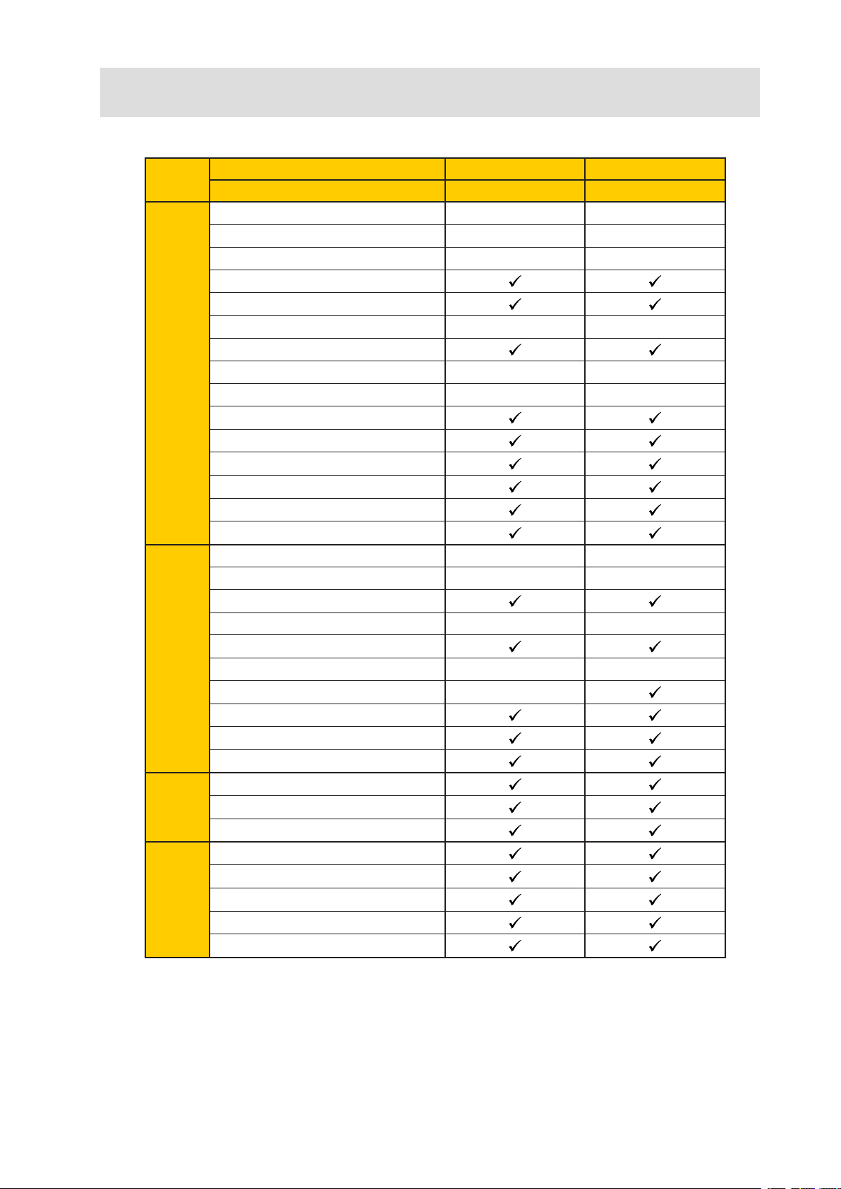
2 Supported Software Features
MAXDATA Model Name FALCON 200 L FALCON 300 L
Embedded Operating System
ICA Client Version 8.2 8.2
Citrix Program Neighborhood Full PN Full PN
RDP Client Version
PowerTerm Emulation Suite
Kerberos (within PowerTerm)
SAP Gui - -
X11R6
XDMCP (number of max. displays) 2 4
Extended Local Xfonts
Font Service (XC + NFS)
CONNECTIVITY
SMB / NFS Mounting
Devicemapping Daemon
ThinPrint Client
Printing via Line Printer (LP)
Printing via TCP/IP
Local Browser Firefox Mozilla
Java Runtime Environment (JRE)
Acrobat Reader
Media Player - -
Flash Player
Real Player - -
INTERNET
Messenger -
PPTP (VPN)
PPPOE (DSL)
Cisco VPN
Smartcard Application
USB Hotplug Automounting Feature
MISC
KVK Support
Full Remote Managability
Shadowing / VNC
Remote RSH / SSH Access
ADMIN
Setup via Bootp / DHCP
PXE Netboot
Flash Linux Flash Linux
5.1 5.1
- -
- -
Note: Hardware Configuration
In the appendix you will find a detailed overview of the hardware configurations and technical specifications of the different models.
MAXDATA FALCON 200 L / 300 L
9
Page 10

10
Page 11

3 Quick Installation
If you carry out the following steps, the terminal can be installed in your network environment
within a few minutes.
• Connect the terminal to a VGA monitor, an AT compatible keyboard with PS/2 or USB connector, a PS/2 or USB mouse, the LAN via RJ45 and AC power.
• Turn on the terminal and wait until the graphical desktop has started (around 30 seconds)
and the window of the application launcher appears on the screen. Highlight the setup entry
and start the Setup either by pressing the START button or double clicking on the setup
entry.
• Select your keyboard layout in the “Input/Keyboard” menu.
• Select your display settings in the “Display” menu.
• Complete the terminal setup program by entering a local IP address in the “Network” sec
tion or keep the default DHCP mode for automatic network configuration.
• Finally “save” the settings, press “OK” and confirm with “Yes”.
The unit will reboot now and will come up with the new settings.
Note:
For detailed session configuration refer to Chapter 6.4.
Virtually every setting is “equipped” with a meaningful Tool Tip. Simply move the pointer over the
setting/option you want to know more about and wait a second.
-
MAXDATA FALCON 200 L / 300 L
11
Page 12

12
Page 13

4 Boot Procedure
4.1 System BIOS
The BIOS looks for extensions in the appropriate memory area. If there is a DOC (Disk On Chip) in
use, the BIOS extension will be detected and executed. If there is a DOM (Disk On Module) or CF
(Compact Flash) in your unit, they are IDE devices and directly treated as hard disks. The next step is
the execution of the master boot record, which starts a secondary stage loader.
4.2 Secondary Stage Loader and Boot Menu
The secondary stage loader provides the user with a menu, which is reached by pressing the “ESC”key when the “Loading Kernel …” message appears on the screen.
You can then choose between 3 boot-options and the possibility to reset the Thin Client to its factory
defaults.
• Quiet Boot
• Verbose Boot
• Emergency Boot (setup only)
• Reset to factory defaults
4.2.1 Quiet Boot
“Quiet Boot” is the standard boot mode; it suppresses all messages from the kernel and starts up
the graphical desktop.
4.2.2 Verbose Boot
If the “Verbose Boot” is chosen, the boot messages are shown and you will have a diagnostic shell,
from which common debug commands (like “ifconfig” etc) can be executed. To leave this shell type
“init 3” and the boot process continues.
4.2.3 Emergency Boot
If you choose “Emergency Boot” (setup only with standard parameter values), the secondary stage
loader looks for a bootable system in the flash and continues the boot process as in the other boot
modes. Emergency Boot basically starts the X Server without the network driver at a resolution of
640 x 480 - 60 Hz and finally starts directly into the setup. This is very useful, if you selected a too
high screen resolution, or chose a wrong mouse type.
4.2.4 Reset to default factory settings
All your personal settings including your password and configured sessions will be lost if you choose
this option. Before the reset will be applied, a warning message is displayed on the screen where
you have to explicitely confirm your decision. If the terminal is protected by an administrator password, you will be prompted to enter it. In case this password is not known anymore, you will have
to contact us via our website www.maxdata.com. Provide the displayed “terminal key” and the
stated firmware version and of course your contact data. Our support will provide a so called “reset
to factory defaults key” for this specific unit. (Every key is valid for one single unit only, to keep this
process the most convenient, but still secure.)
4.3 Networking
After loading the kernel the network configuration follows. Three different ways can be chosen to
include the terminal into the network environment. According to the settings of the terminal DHCP,
BOOTP or manual configured IP address can be used.
4.4 X Server
The last step of the boot procedure is the start of the X-Server and the local window manager.
MAXDATA FALCON 200 L / 300 L
13
Page 14

14
Page 15
5 Setup (Global Settings)
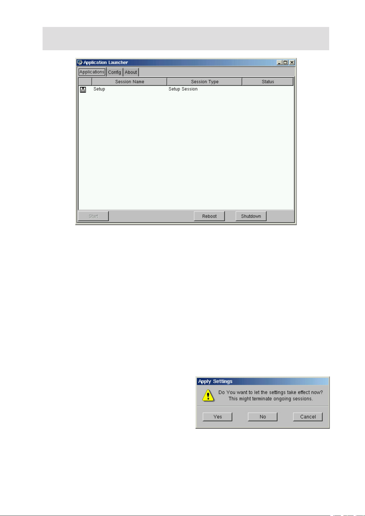
After the boot procedure has completed, such a desktop will be displayed on the screen.
The “Application Launcher” starts automatically because it‘s set to “autostart & restart” by default.
Because the “Setup” program is the central configuration tool for all global settings of the Thin Client,
a “Setup”-Session is also predefined.
5.1 Starting the Setup
You can reach the Setup in three different ways:
• Select the “Setup” entry in the “Application Launcher” and double click it or press the “Start”
button in the lower left corner of the window.
• Click on the “MAXDATA” icon in the very lower left corner and in the popup select “Setup”.
• Clicking on any free space on the desktop with the right mouse button will cause a dropdown
list to appear; again select the “Setup” entry to proceed.
These are the default settings to reach the Setup. You can configure it to be reachable in every com
bination of this three possibilities within the “Application Launcher” (see Chapter 6).
5.1.1 Leaving the setup
In general, every particular setup page provides an “OK”, “Cancel” and “Save” button.
After all configurations in a particular setup
section are made and you want to save your
settings without leaving the setup program,
click on the “Save” button.
If you did not change any settings and you want to exit the setup, click on the “Cancel” button.
In case you changed settings, leaving the setup with “OK” will prompt you with the above “Apply
Settings” Popup. Decide if you want to let the changes take effect immediately (“Yes”), save and let
it become effective on next reboot (“No”), or “Cancel” to stay within setup.
-
MAXDATA FALCON 200 L / 300 L
15
Page 16
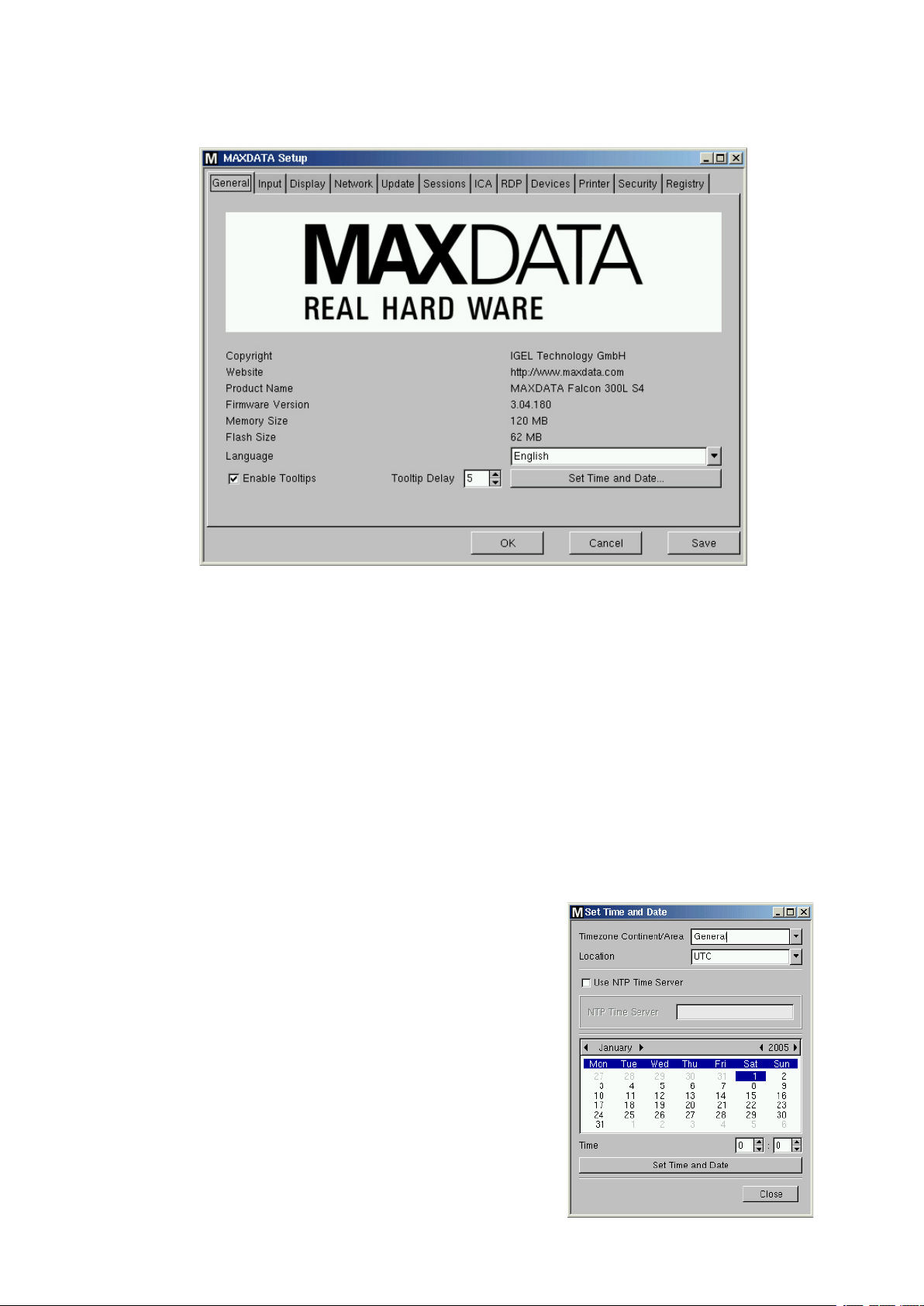
5.2 General
When the “MAXDATA Setup” has been started, first the “General” page appears on the screen.
Some system information additionally to the product name are provided on this page.
Some vital informations like the firmware version, the memory size (RAM) and the flash size.
• Language
Select the appropriate language from the list. (Currently “German” and “English” only.
Note:
The chosen language is the user interface language, so it‘s valid for all local applications.
• Tooltips
These are small dropdown windows with a short description of the pointed menu entry. This tooltips
open up if you stay on a menu entry with your mouse pointer for the entered amount of “Tooltip
Delay” time (in tenth of seconds).
• Set Time and Date …
Click on the “Set Time and Date” button to open up this
dialog-box.
Make your changes and confirm it by pressing the “Set time
and Date” button once, then close this page.
If such a Time Server is available in your network, you may
also use the “Network Time Protocol” (NTP) to request the
proper time and date automatically during each bootup
16
Setup (Global Settings)
Page 17
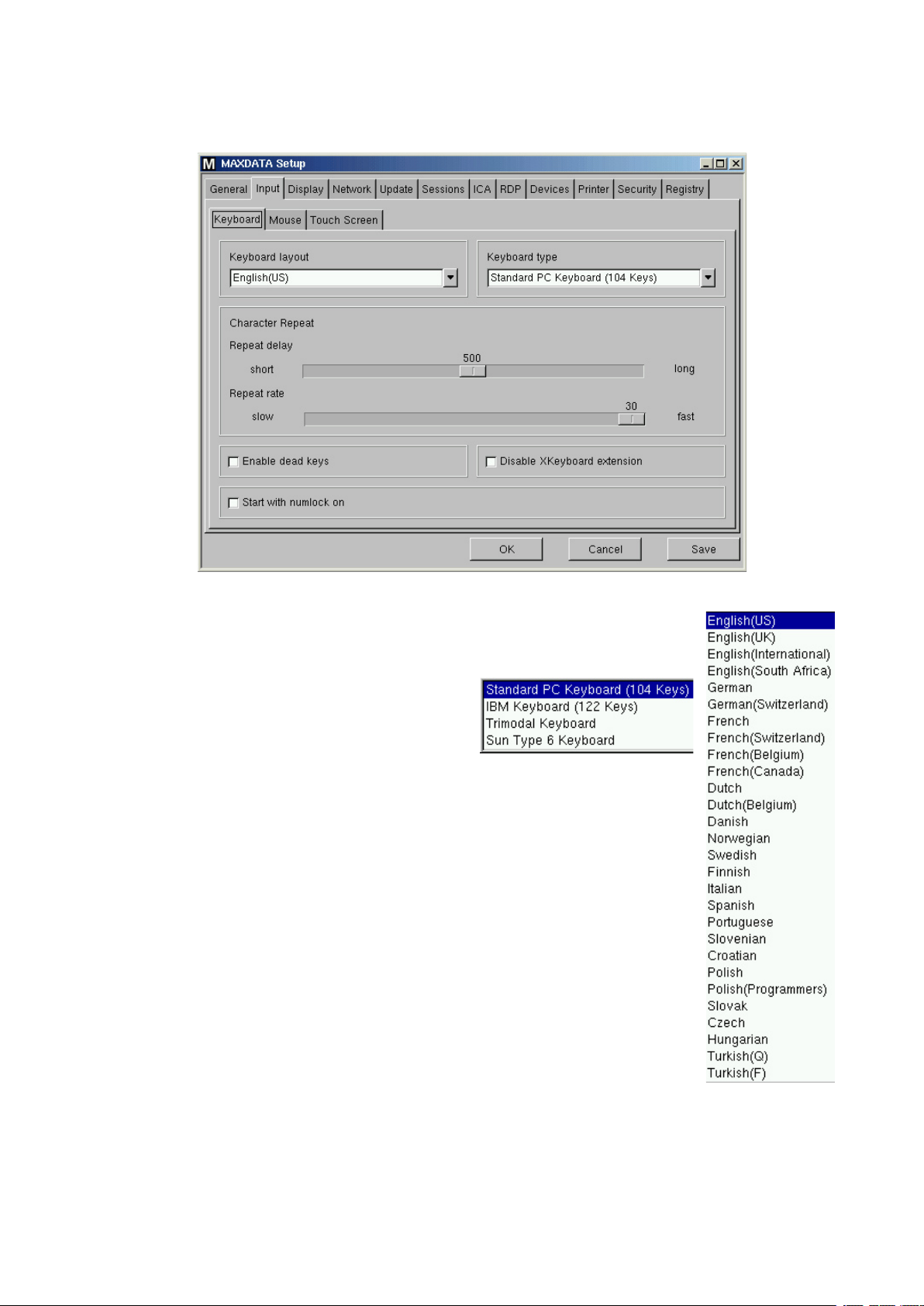
5.3 Input
5.3.1 Keyboard
• Keyboard Layout
Select your “keyboard layout” here. The layout will be valid for all parts of the
system including emulations, window sessions and X applications. (Table to the
right shows all currently supported layouts.)
• Keyboard Layout
Choose your keyboard type from the available
from this drop box:
• Character Repeat
In this section you can set the auto repeat behavior for the keyboard:
o Repeat Delay
Sets the delay time (in milliseconds) between pressing a key and the start
of the auto repeat mode.
o Repeat Rate
Sets the number of repeated characters per second.
• Enable Dead Keys
Enable this function if the chosen keyboard layout uses dead keys for special
characters.
• Disable Xkeyboard extension
Activating this button disables the language specific keymappings of the local
X-Server. (Thus you will in fact have US keyboard layout.)
Within an XDM connection, keys may though be mapped by the server.
• Start with Numlock on
Enable this checkbox, if you want Numlock to be activated during the boot process automatically.
MAXDATA FALCON 200 L / 300 L
17
Page 18
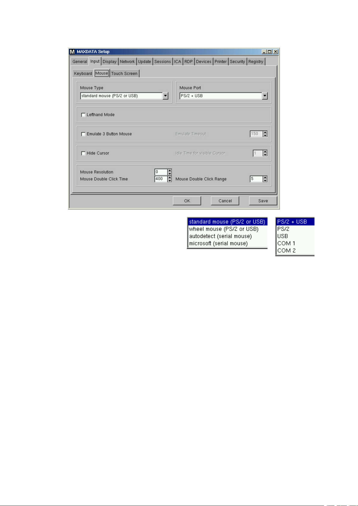
5.3.2 Mouse
• Mouse Type and Mouse Port
Set the type and port of the attached mouse
device from these two drop down boxes:
• Lefthand mode
Changes the orientation of the mouse to left handed by swapping the mouse buttons.
• Emulate 3 Button Mouse (not supported with serial mouse)
Enable/disable the emulation of the third (middle) mouse button for mice which only have two physi
cal buttons. The third button is emulated by pressing both buttons simultaneously.
• Emulate 3 Button Timeout
Sets the timeout (in milliseconds) the driver waits before deciding if two buttons where pressed
“simultaneously”, if 3 button emulation is enabled.
• Hide Cursor
In case you don‘t use a mouse or you want to show some self-running presentations, you may set a
mouse cursor idle timout. To completely disable the Mouse Cursor, set timeout to zero.
• Mouse Resolution
Here you set the resolution of your mouse in counts per inch.
• Mouse double click time
The maximum interval (in milliseconds) between two successive mouse clicks to recognize a double
click may be altered here.
-
• Mouse double click Range
The maximum distance (in pixels) between two successive mouse clicks to recognize a double click
may be altered here.
18
Setup (Global Settings)
Page 19

5.3.3 Touchscreen
Note:
To get into and navigate within the setup, it‘s recommended to do the initial
attached Mouse. You may also use the “Emergency Boot” and navigate through the setup with the
keyboard by using t
• Touch Screen Type
The supported types are currently “Elographics” and “MicroTouch”.
• Touch Screen already calibrated
After enabling the touchscreen functionality, you have to calibrate it minimal once. As long as you do
not activate this checkbox, the calibration will automatically start at every boot up.
• Swap X and Y Values
Activate this option in case you rotate the panel by 90 degrees (Portrait mode).
• Minimal and maximal X and Y Values.
These will be set by the calibration tool. (You may also manipulate them manually)
• Untouch Delay
The maximal time (in milliseconds) allowed between two touch events still beeing interpreted as
one. E.g. while moving Windows by drag&drop, unintentional untouch events may occur. Increasing
this value prevents the Thin Client from interpreting this as two separate touchs.
• Report Delay
Defines the time (in milliseconds), the Screen must be touched to recognize it as touch event.
• Baud Rate
Set the communication speed via the selected port. (In doubt, refer your panel‘s manual.)
he cursor arrows, t
ab and space bar.
configuration with an
• Touch Screen Interface Port
You can attach the Touch Screen to wether COM1 or COM2. Set the selected port here.
• Set driver specific defaults
Click here once after changing the Touch Screen Type or to reset the settings to it‘s defaults.
MAXDATA FALCON 200 L / 300 L
19
Page 20
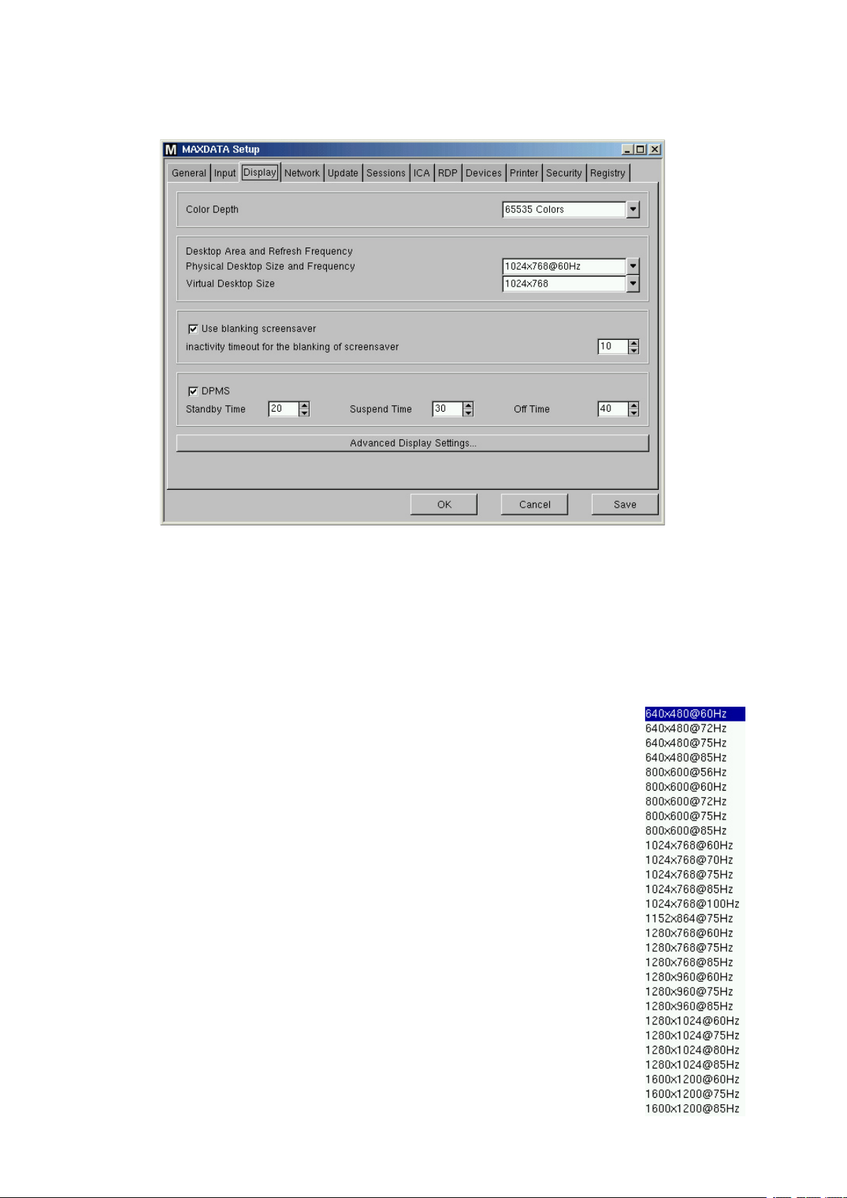
5.4 Display
5.4.1 Global Display Settings
• Set driver specific defaults
This menu allows you to specify the dekstop color depth from these available:
- 8 bits per pixel (256 colors)
- 16 bits per pixel (High color / 65k colors)
- 24 bits per pixel (True color / 16,7million colors).
Note:
Make sure that the display unit connected to the Thin Client supports
case you accidently set it too high, refer section 4.2.3 “Emergency Boot”.)
Desktop Area and Refresh Frequency
• Physical Desktop Size and Frequency
Select the needed resolution from this menu. The available resolutions depend on
the previously chosen color depth and the hardware model of your Thin Client.
• Virtual Desktop Size
The virtual resolution is used for panning. That means that the virtual screen is
bigger than the physical screen. So the “Virtual Desktop Size” can never be smaller
than the chosen entry of the “Physical Desktop Size”.
Note:
Both of the desktop size entries but also the value of the color
each other, as well as the used hardware (Thin
Client model).
depth depend on
the selected settings! (In
Screensaver and DPMS
• Blanking Screensaver
If the screensaver function is activated a blanking screensaver is used after the
period of time (in minutes) you have defined.
• DPMS
See 5.4.2.2.
20
Setup (Global Settings)
Page 21

5.4.2 Advanced Display Settings
Depending on on the Thin Client model, you may start up to four local X servers.
By default, the first X server is enabled and preconfigured. The settings in the dialog-box
are identical with the global display settings (see previous page).
Changes in display 1 will automatically be set in the global display page and vice versa.
“Display 2”, “Display 3” and “Display 4” are the corresponding pages of the three additional X
server, which are disabled by default. (Not all models do in fact have four but only one additional.)
The available dialog-boxes are all the same for the four displays (except the “enable Display” check-
box), so we used “Display 1” as reference for the descriptions.
Note:
Remember t
RAM, you must be careful here! In doubt, upgrade the installed RAM.
hat every display consumes a certain amount of memory! If
your unit is low on
“Display 1”
5.4.2.1 Resolution
• Access Control
If enabled (default) this option prevents other hosts to have access to your display (see also section
5.4.2.4 for details on how to grant access for specific hosts).
• Exit sequence
This option allows you to disable the sequence <Ctrl>+<Alt>+<Backspace> to exit the X server.
• Console Switching
Press this button to disable the console switching with <Ctrl>+<Alt>+<Fn>
• Alternate switching sequence
Here you can choose between <Alt>+<SysRq>+<Fn> and <Ctrl>+<Alt>+<Fn> to switch between
displays.
MAXDATA FALCON 200 L / 300 L
21
Page 22
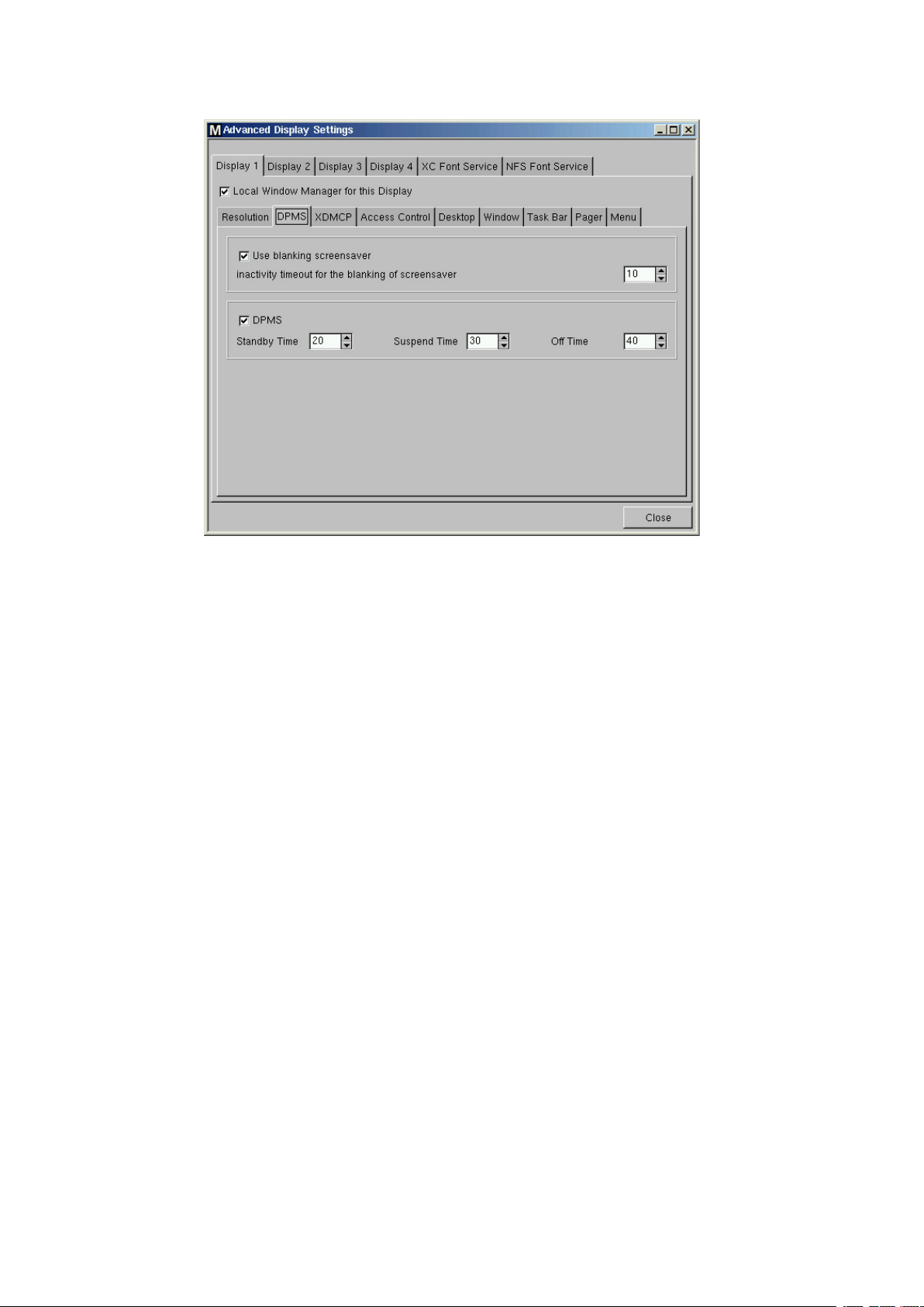
5.4.2.2 DPMS
If your monitor supports “Display Power Management Signaling” it allows more functions (energy
saving) than just a screensaver.
There are three different modes called
are activated after their adjustable time loops (in minutes) ran off.
Enabling DPMS with the default time settings activates the “power off mechanism” of the monitor
as follows:
After 10 minutes the display switches to “blank” (Standby mode), after further 10 minutes it sets the
first current savings level (Suspend mode: Switch off the high voltage), and after further 10 minutes
the monitor changes into the “Off” mode.
Note:
All levels are passed through naturally only if t
runtime.
“Standby mode”, “Suspend mode” and “Off mode”, which
he X server receives no ne
w inputs during this
22
Setup (Global Settings)
Page 23
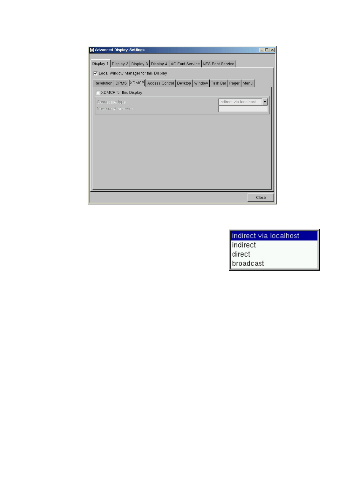
5.4.2.3 XDMCP
Click the corresponding button to enable the XDMCP functionality for the “Display 1”.
• Connection type
Select the appropriate “Connection Type” here.
If you select
vided from the first XDMCP server answering on the broadcast
request.
In the case you select
at boot-up time. From this list you must select the host which provides the “Graphical Logon”.
• Name or IP of Server
If you select
Specify the Name or the IP address of the XDMCP server you want to use.
In the “direct” mode you will get your “Graphical Logon” directly from the XDMCP server you have
specified in the entry field, in the case you have selected the “indirect” mode a list of available
XDMCP servers will be provided from the server you specified.
Note:
Make sure that your Display Manager Daemon (XDM, KDM, GDM, …) is running and the access
permission is given on the remote host.
“broadcast” the “Graphical Logon” will be pro-
“indirect via localhost” connection type a list of XDMCP hosts is displayed
“direct” or “indirect” connection type, the “Name or IP of Server” field is enabled.
MAXDATA FALCON 200 L / 300 L
23
Page 24
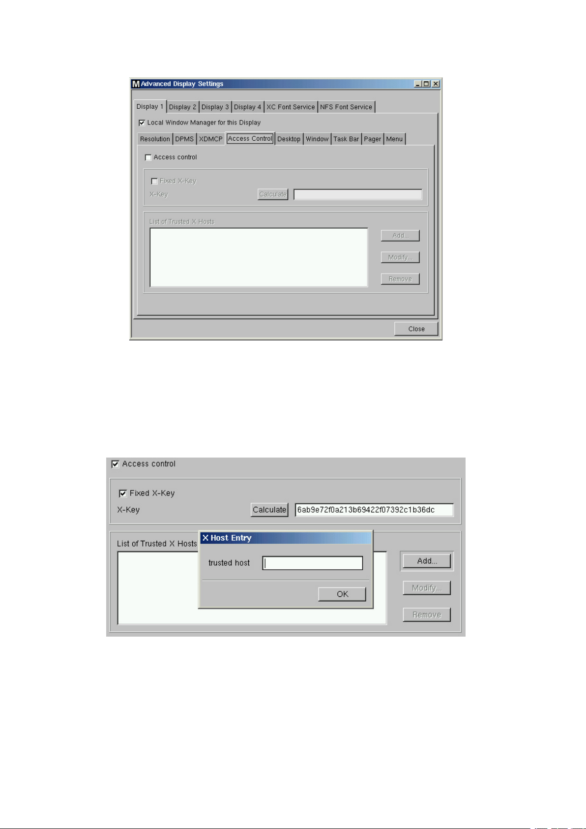
5.4.2.4 Access Control
The Thin Client provides an access control that is activated by default. If you disable this “Access
Control” it will be possible for everybody from any UNIX host to have access to your terminal‘s
display.
• Fixed X-key
You can allow specific users to get permanent remote access to the Thin Client. Therefore you need
to activate this option, press the “calculate” button and enter that 32 digit key into the Xauthority file
of the user‘s machine.
List of Trusted X Hosts
Click the “Add…” button to open the “X Host Entry” box. Enter the name of the remote host (not
the IP address) you want to add and confirm with “OK”.
24
Setup (Global Settings)
Page 25
5.4.2.5 Appearance
The following five dialog-boxes allow you to configure the appearance and the behavior of the “Desk-
top”, “Windows”, “Task Bar”, “Pager (Virtual Screens)” and the “Start Menu”.
Note:
Except the “Pager”, these masks are not described in detail, please refer t
o the tool tips.
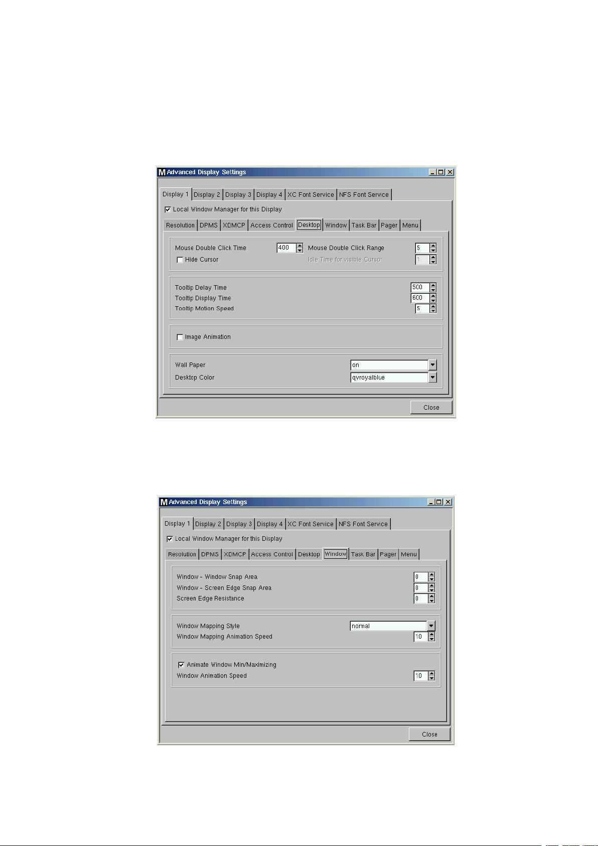
Desktop
The “Desktop” dialog-box contains two additional properties of the mouse behavior, allows you to
manipulate the tool tip timings and the appearance of the desktop.
Window
The “Window” dialog-box enables you to define the window snap behavior, the style how to map/
unmap windows and to enable/disable the animation of window minimizing and maximizing.
MAXDATA FALCON 200 L / 300 L
25
Page 26
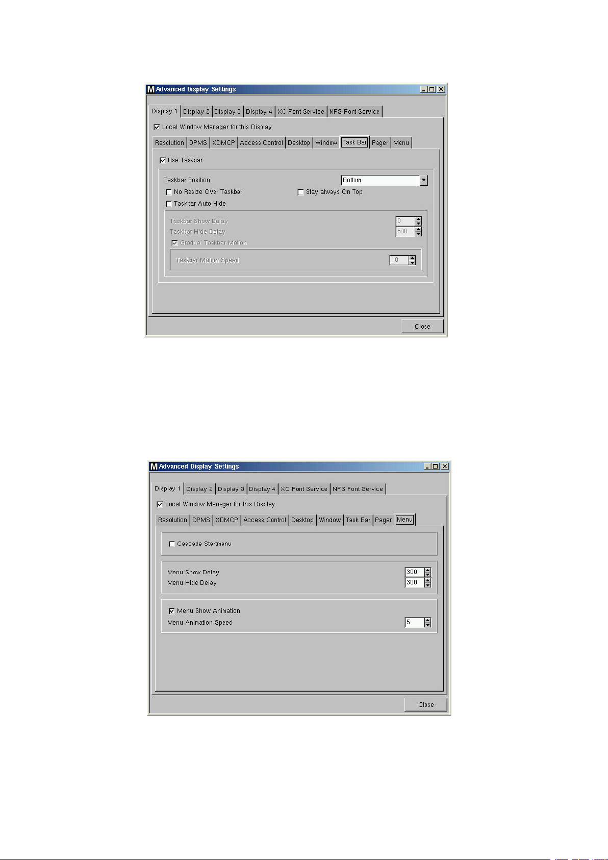
Task Bar
The “Task Bar” dialog-box allows you enable/disable the usage of the task bar and to define its
behavior.
Pager
(See next page, please)
Menu
The “Menu” dialog-box allows you to define the behavior of the start menu.
26
Setup (Global Settings)
Page 27
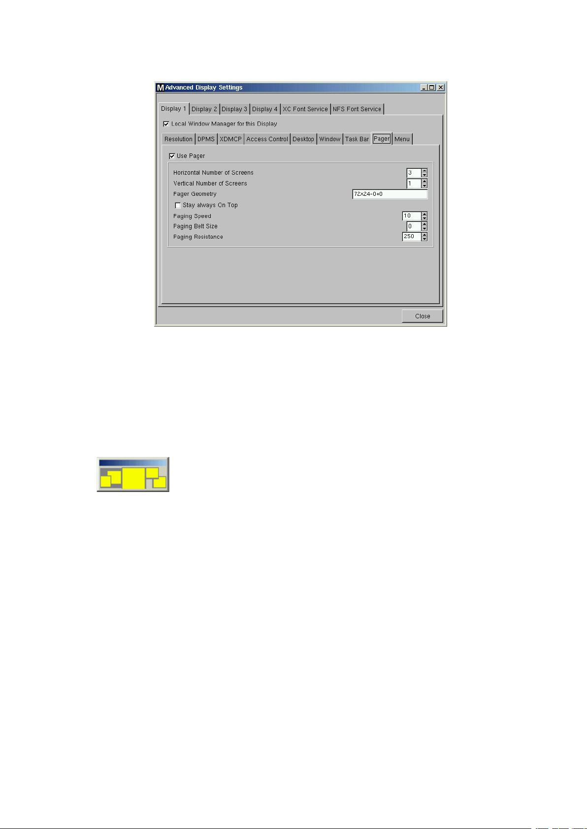
Pager
The “Pager” dialog-box allows you to enable/disable the usage of multiple “Virtual Desktops” like it
is common in Linux.
The “Pager” is a window with “Virtual Screens” that you can use to easily move from one open
application to another. This window is displayed in the upper right corner of the desktop screen.
It could contain a single “Virtual Screen”, or a higher number of “Virtual Screens”.
By using the Pager, you can for instance switch between full-screen Applications by one sole Mouse
click.
To give a little example:
-
This exemplary Pager contains three virtual desktops.
The first of them is active (dark grey) and shows the “Application Launcher” and the “Setup”. On
the second one is a full-screened Browser window.
Two different local shells are running on number three.
Now instead of minimizing and maximizing all that sessions or toggling them via keycombina
tions, you simply mouse-click on the desired Screen and get back to it exactly like you left it before
(except after Reboot).
Have a look at the tool tips in order to modify the pager to your needs.
Note:
Enable the option “Stay always on top” to always have it on top of every window.
Note:
All running sessions of all virtual screens will be accessable via the task bar in each of the
screens.
MAXDATA FALCON 200 L / 300 L
-
27
Page 28
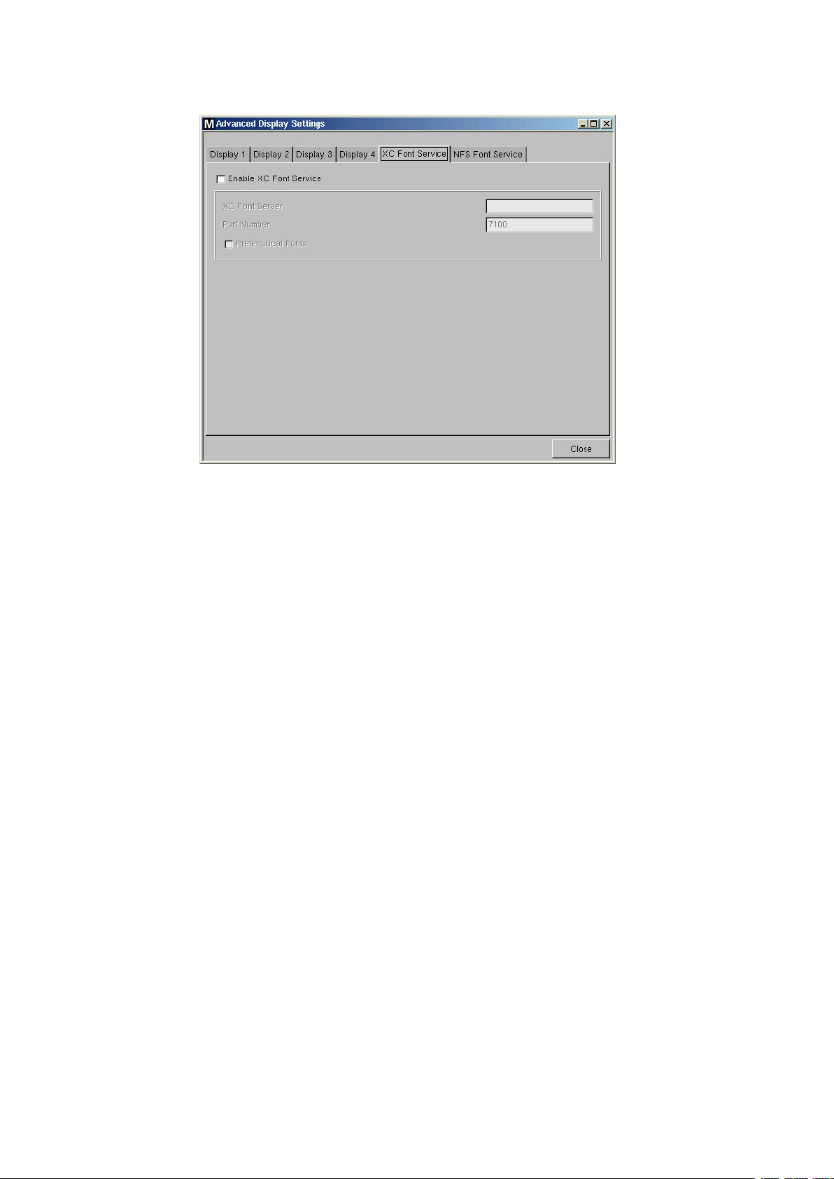
5.4.2.6 XC Font Service
If you require fonts in addition to those that the Thin Client provides, the XC Font Service can be
used.
Note:
This is a service that has to be installed and completely configured on the server.
The advantage of using the XC Font Service instead of NFS is the better performance of XC Font
Service.
Click the “Enable XC Font Service” button to enable the following entry fields.
• XC Font Server
Specify the server on which the XC Font Service is running.
• Port Number
Specify the port number where the font service is listening. (default is port number 7100)
• Prefer Local Fonts
Enable this option to use local fonts before asking the font server.
28
Setup (Global Settings)
Page 29
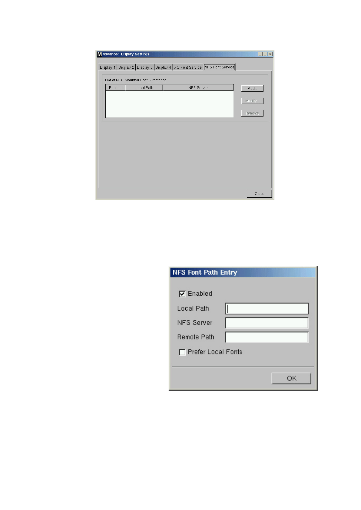
5.4.2.7 NFS Font Service
Another way of importing additional fonts is the usage of the NFS Font service. In addition, there
is the advantage that the mount point for the fonts is configurable, which is necessary for certain
remote applications that search for their fonts in a specific path.
If you want to use the “NFS Font Service”, you have to define and enable an “NFS Font Path Entry”,
which will be added into
To do so, click the
“Add…” button to open the following “NFS Font Path Entry” dialog-box:
“List of NFS Mount Font Directories”.
• Local Path
Specify the “Local Path” to the mount
point.
• NFS Server
Enter the name or the IP address of
the server which provides the font
directories via NFS.
• Remote Path
Specify the path on the server side
where the fonts are available.
• Prefer Local Fonts
Enable this option to use local fonts
before asking the font server.
Note:
Don‘t forget to click the “Enable” button to activate your entry.
Note:
On server side you have to export the font directory via NFS read only for the Thin Client.
MAXDATA FALCON 200 L / 300 L
29
Page 30
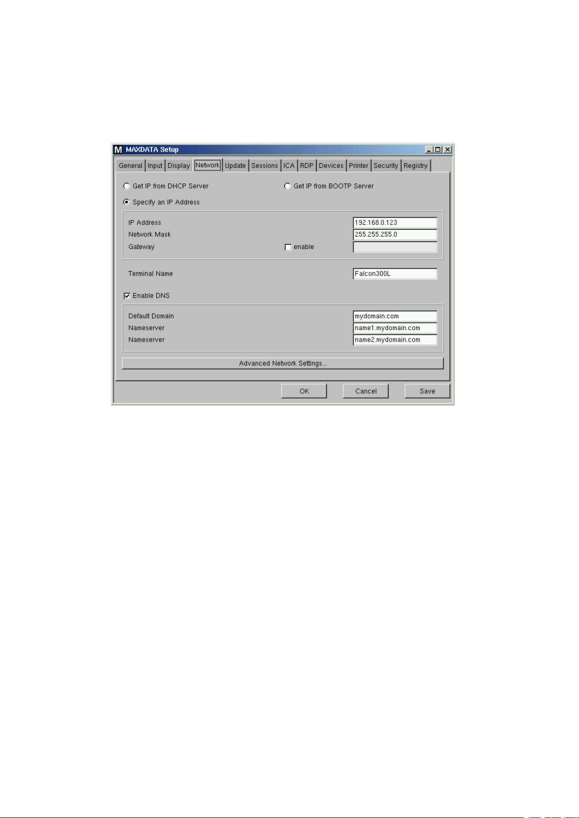
5.5 Network
5.5.1 Main Network Settings
The main “Network” page allows you to configure the network settings on the Thin Client side.
Automatic network set up by using DHCP and BOOTP protocols, but also manual network configu
ration can be chosen.
-
• DHCP
DHCP stands for “Dynamic Host Configuration Protocol” and enables the Thin Client to extract its
IP-address, network mask, DNS, gateway and other network configurations from a DHCP server.
• BOOTP
Using BOOTP allows the Thin Client to obtain the IP address, network mask, DNS, gateway and
other network configurations from a BOOTP server database.
Note:
The transfer of either a setup.ini or boot script is supported. BOOTP is
boot image from a server and to boot this image like the classical meaning of using BOOTP
suggests.
• Specify an IP Address
Click this button to set the network settings manually instead of looking for a DHCP server. Make
sure that the fixed IP you enter is not accupied by another machine in your network. If you have to
“Gateway” to route the data packets to and from the target network, so click the “enable”
use a
button and enter the gateway IP address.
• Terminal Name
Enter the local name of the Thin Client, otherwise the name “MAXDATA-<MAC-address>” will
begenerated.
not used to get a
• DNS
Click “Enable DNS” button to configure the Domain Name Service. Set the “Default Domain” the
unit should work in and the IP of up to two Name Servers, which will be queried after another.
30
Setup (Global Settings)
Page 31

5.5.2 Advanced Networks Settings
5.5.2.1 LAN Interfaces
By default the “onboard” network hardware is used and you have configured the basic network
settings in the “Network” page described before.
Now after you have entered the “Advanced Network Settings” section this settings are taken over to
the corresponding “eth0” dialog-box of the “LAN Interfaces” page.
There are three additional dialog-boxes to configure the optional “LAN Interfaces” as there are:
The configuration masks of eth1 and tr0 are exactly the same then eth0 (except the network
speed).
• th1
If you installed an optional ethernet card in the available
PCI/ISA slot (only available in MAXDATA FALCON 300 L),
use this dialog-box to configure the LAN interface called
“eth1”.
In case you encounter problems with the Auto Sense
function in your network, you can set a fixed network
speed.
See the box to the right for possible speeds for both,
eth0 and eth1.
• tr0
If you have installed an optional Token-Ring card in
the available PCI/ISA slots (only available in MAXDATA
FALCON 300 L) use this dialog-box to configure the LAN
interface called “tr0”.
Like described above (“eth1”), you may set a fixed speed
for Token Ring as well.
• wlan0
(see next page)
MAXDATA FALCON 200 L / 300 L
31
Page 32

Wireless LAN configuration
If you have installed an optional Wireless-LAN card in the available PCI/ISA slots (only available in
MAXDATA FALCON 300 L) use this dialog-box to configure the LAN interface called “wlan0”.
In case you want to use a Wireless-LAN PCMCIA card, you can use the onboard PCMCIA adapter
of the MAXDATA FALCON 300 L.
Note:
These dialog-boxes are not described closer, because they are w
tool tips. Please also refer the manual of your WLAN equip
ell explained by the available
ment.
32
Setup (Global Settings)
Page 33

5.5.2.2 Analog Modem
To set up a WAN connection with the Thin Client you can use an analog modem.
There are different modem types, that can not be used with our Thin Clients. Especially so called
WIN modems will not work. All external modems that are connected to the COM ports or internal
modems that can be configured to behave like an external modem will work. (if possible, prefer
modems with a “Rockwell” chip)
Note:
Internal Modems are only supported by MAXDATA FALCON 300 L.
The following dialog-box allows you to configure the basic modem settings and specific PPP con-
nections:
• Modem Port
Specify the serial port where the modem is connected . (use COM 1 + COM2 for external modems
and COM 3 + COM 4 for internal modems)
• Port Speed
Specify the speed of the port where the modem is connected.
Note:
This is not the speed of the modem, but the speed of the communication bet
Thin Client in baud. This means this speed should be set higher than the modem speed to guar-
antee that data transfer can run with full modem
• Dial Mode
Specify the dial mode of your phone line.
• Initstring
Specify a special initstring for your analog modem, if the standard initstring does not work.
• Set default route
This option can be used to set the default route to the PPP connections.
To create a new PPP connection, click the “Add…” button and the following dialog-box appears on
the screen (see next page):
speed.
ween m
odem and
MAXDATA FALCON 200 L / 300 L
33
Page 34

PPP Provider Settings
• Phone Number
Specify the phone number of your provider.
• PPP Login and Password
Select the authentication type for this modem connection
from this list:
(Only a few provider use the CHAP method although it is the
safer one because of the usage of encryption.)
• Automatic DNS
This option allows you to choose between automatic or manual DNS configuration.
If you choose manual configuration you have to enter the IP address of your provider‘s
server”.
• Automatic IP
This option allows to choose between automatic or manual IP address configuration. The default setting is set to automatic, which means that the Thin Client gets its IP address dynamically from the
provider‘s DHCP server. In case you have deactivated the automatic mode, you have to enter the
Thin Clients “Local IP” and your providers “Server IP” manually.
For details on the “
Title” Tab, see Chapter 6.4, please.
“Name-
34
Setup (Global Settings)
Page 35

5.5.2.3 ISDN
The second way to set up a WAN connection with the MAXDATA Thin Client is using an ISDN card.
Note:
The currently supported ISDN cards are the AVM Fritz (version 1.0 and 2.0 as
combi card) and the U.S. Robotics PCI card. This feature is avai
300 L which provides the additional
Note:
Because the ISDN configuration is nearly the same like the Modem configuration, we only describe
the differing resp. additional features / options below.
PCI slot.
lable only for the MAXDATA FALCON
well as the ISDN/DSL
• MSN (Multiple Subscriber Number)
In this field you have to provide the MSN of your ISDN installation. This number is regularly built by
the phone number being used for the device without predial.
• Connection Timeout
Specify the period of time (in seconds) of inactivity after which the ISDN connection will be discon
nected automatically by the Thin Client.
• Enable Autodial during Boot
Enable this checkbox to make the client connect to your host before the desktop boots up.
To create a new connection, click the “Add…” button and the following dialog-box appears on the
screen (see next page):
-
MAXDATA FALCON 200 L / 300 L
35
Page 36

ISDN Provider Settings
Enter your provider settings here.
Options (Callback)
The callback feature enables your Provider to call back the Thin Client (mainly used for home workers). Please refer the expressive tool tips for details and syntax.
36
Setup (Global Settings)
Page 37

5.5.2.4 ADSL
• Enable Autostart during Boot
In oder to to set up a fully autostart-configured client, you may need to dial in first. Enable this check
box to make the client connect to your host before the desktop boots up.
Via the
“Add…” button, you set up new connections:
-
First, enter your account‘s configuration. Next, select if you connect via a DSL modem connected to
the network interface or if you use an internal PCI device. Also, set if the DSL connection should be
network interface eth0 or eth1 and the protocol to be used.
MAXDATA FALCON 200 L / 300 L
37
Page 38

The options tab enables you to define name service and IP configuration for the DSL connection.
Usually, this will be handed over by the RAS server of the provider, so by default, both DNS and IP
are set to “automatic” by default.
The tuning tab lets you basically set two things; the connection‘s duration and network packet size
and error handling.
• Persistant Connection and On-Demand Connection
Select, if your connection should be kept or only be used on demand only if needed.
If on-demand is chosen, the connection will disconnect after the given timeout (in seconds).
• MTU and MRU
Set the maximum size of pakets (maximum transfer units and maximum receive units).
38
Setup (Global Settings)
Page 39

5.5.2.5 PPTP
PPTP (Point-to-Point Tunneling Protocol) is one of the most common virtual private networks (VPN)
protocol enableing remote users to access corporate networks securely.
• Enable Autostart during Boot
In oder to to set up a fully autostart-configured client, you may need to dial in first. Enable this check
box to make the client connect to your host before the desktop boots up.
Cklick the
“Add…” button to set up new connections:
-
Enter the necessary settings to dial in to the RAS server on the desired remote station. Further,
you select the network device and if a dialup connection should be used.
MAXDATA FALCON 200 L / 300 L
39
Page 40

In the options tab you define name service and IP settings for the PPTP connection.
As this will usually be handed over by the RAS server of the remote station, both DNS and IP are set
to “automatic” by default.
The following three setup pages let you set up additional network routes.
40
Setup (Global Settings)
Page 41

5.5.2.6 Cisco VPN
Please refer the third party documentation “Cisco_VPN_Client_User_Guide.pdf” for details on proper
configuration and syntax details.
We do only show the according setup pages and give a rough description here.
Initially, set the host to authenticate against.
You also set the desired connection to be used here.
MAXDATA FALCON 200 L / 300 L
41
Page 42

Enter the account‘s details here.
Certificate global settings like the URL and domain for them have to be set in this tab.
Click the
42
“Enroll” button for the certificate‘s details (see next page).
Setup (Global Settings)
Page 43

This tab is for the certificate‘s very details.
MAXDATA FALCON 200 L / 300 L
43
Page 44

5.5.2.7 Routing
Use this dialog-box to specify additional network routes, if necessary.
(The Interface field needs “eth0”, “eth1”, “tr0” or “wlan0”.)
Alltogether you can define up to additional 5 routes .
44
Setup (Global Settings)
Page 45

5.5.2.8 Hosts
If no DNS (Domain Name Service) is used you can provide a list of hosts to translate between
their “IP addresses”, “Full Qualified Hostname” and “Short Hostname”.
Use this dialog-box to create this
“Host List”.
Click “Add…” to open the following “
Host Entry” dialogbox:
Host entry
• IP Address
Enter the IP address of the host you
want to add.
• Full Qualified Hostname
Enter the “Full Qualified Hostname”
(e.g.mailserver.maxdata.de>).
• Short Hostname
Enter the “Short Hostname” (e.g.
<mailserver>).
After all entries are made please confirm this by clicking “OK”.
Now the specified host will be added to the “Host List”.
MAXDATA FALCON 200 L / 300 L
45
Page 46

5.5.2.9 NFS
NFS (Network File System) enables you to share files via the network. The NFS server exports a file
system and the NFS client (your Thin Client) associates this to a mount point of its own file system.
So afterwards the exported file system will be a logical part of the Thin Client‘s file system, while it
physically remains on serverside.
Note:
To set up NFS mount, the server has to be configured first. For detailed infor
refer to the corresponding “man pages” of your server operating system.
Use this dialog-box to define NFS mounts on the Thin Client side:
mation about “NFS”
Click “Add…” to open the following “
NFS Mount Entry” dialogbox:.
NFS Mount Entry
• Enabled
By default the “NFS Mount Entry” is ena
bled and mounted at every system start.
(Disable the entry if the shared file system
is not needed permanently.)
• Local Mount Point
Specify the “Local Mount Point” where the
share should be mounted in the local file
system of the Thin Client.
• Server
Enter the name or the IP address of the
NFS server that provides the share.
• Directory Name
Enter the directory name as it is exported
by the NFS server.
-
46
Setup (Global Settings)
Page 47

5.5.2.10 SMB
The SMB protocol is very useful because it is used by Microsoft Windows NT, Windows 95/98, Win-
dows 2000 and Window XP to share disks and printers. So as Unix (including Linux) can also handle
this protocol with the Samba suite tools, it is possible to share disks and printers with Windows
hosts.
So it is possible on the Thin Client to mount SMB shares from Windows or Unix Samba hosts.
Note:
The SMB (Server Message Block) protocol is only used for sharing files over the network (no print-
ers). It is necessary that the shares you want to mount are created on the Windows or Unix host
first!
Click “Add…” to open the following “SMB Mount Entry” dialog-box:
SMB Mount Entry
• Local Mount Point
Specify the “Local Mount Point” where the
share should be mounted in the local file
system of the Thin Client.
• Server
For a Windows host, the NetBIOS name
has to be entered here. In case of a Unix
samba host, the host name or IP address
is to be used.
• Share Name
Enter the directory name as it is exported
by the Windows or Unix samba host.
• User Name / Password
Enter the user name and the password
of your account on the Windows or Unix
samba host.
• Enabled
By default the “SMB Mount Entry” is enabled and mounted at every system start.
• User writeable
Activating this also enables the desktop user to write data (otherwise, only “root” is).
MAXDATA FALCON 200 L / 300 L
47
Page 48

5.5.2.11 Filetransfer
• Enable setup from remote Server
In case you use BOOTP+TFTP or DHCP+TFTP to spread the “setup.ini” or boot scripts, this option
enables the transfer from a remote server at boot time.
• Filetransfer timeout
Defines, how long the Thin Client should try to get it‘s configuration from the server (in seconds).
In case it does not succeed within the chosen time, the local configuration is used
• Disable on Update
This option is important for firmware updates.
Because a reboot takes place during the update process, there might be a heavy mixup of configura
tions, if the Thin Client would still get it‘s setup from remote. This could end up in a half updated unit
that has to be reconfigured completely or even worse.
Note:
Leave t
interactions of the update and the filetransfer processes.
he “Disable on Update” option untouched while you do not comple
tely understand the
-
48
Setup (Global Settings)
Page 49

5.6 Update
The “Update” page shows you a simple dialog for updating the Thin Client‘s firmware via FTP.
The common procedure to update your Thin Client(s) is as follows:
1) Download the wanted firmware image from our FTP-Server http://ftp.maxdata.de/t_index.
asp?info=/info/MAXDATA_Falcon_Thin_Clients (there are sub-directories named after the
models).
2) Unpack the *.zip file, as this is the usual way we provide updates.
3) Put all files into the designated directory on your local FTP server
4) Enter the necessary settings (see below for details) and press “Update now”. Now the update
process will advance completely automated.
Note:
The default values “update.maxdata.de” etc are exemplary only, you will not be able to update
directly from our FTP Server! The update procedure cannot be done via PPP /ISDN connections.
The following information must be provided in order to start the update process:
• Server Name
Enter the name or the IP address of the used FTP server.
• Server Path
Enter the name of the directory, you stored the update files in (relatively from the FTP root directory).
• User Name
Enter the User ID / FTP account name.
• Password
Enter the corresponding password of that user / account.
MAXDATA FALCON 200 L / 300 L
49
Page 50

5.7 Sessions
In circumstances when the “Application Launcher” itself is unaccessable, you may manipulate your
sessions directly via the setup here.
Refer Chapter 6 “Application Launcher” for details on how to configure your sessions.
50
Setup (Global Settings)
Page 51

5.8 ICA (Global ICA Settings)
This section describes how to configure the “Global ICA Settings”, that will be valid for all ICA sessions.
Note:
These are the default values for all ICA sessions. Most of this properties (especially color depth,
resolution and server-IP or name) can be altered for each session separately (see section 6.4.6)
5.8.1 Window
• Default Number of Colors
You are allowed to set the default number of window colors to 256 (default), Thousands (hi color)
or Millions (true color). The color depth your sessions can run in also depends on your Metaframe
server
• Approximate Color
Because of differences in the color palettes used between the ICA Client (and the application it displays) and the “Thin Client” desktop, an annoying flashing can occur when switching context on a
pseudo-color display. The ICA Clients color approximation scheme eliminates this flashing by using
colors from the local desktop palette to display the ICA window session.
Enable “Approximate Color” to eliminate color flashing when switching context.
Note:
This only applies if the X server is running in 8 bit color mode.
• Resolution
Set the default window size by adjusting the values for the
the “Default Vertical Resolution”.
“Default Horizontal Resolution” and
MAXDATA FALCON 200 L / 300 L
51
Page 52

5.8.2 Server Location
• Server Location
The “Server Location” (also called server browsing) provides a method for a network-connected
Citrix ICA Client to view a list of all Citrix servers and Published Applications that are accessable on
the network and using the chosen browsing protocol.
The default functionality for server location is “auto-locate” (broadcast). With the “Auto-Locate” func
tion the ICA Client broadcasts a “Get nearest Citrix server” packet. The address of the first Citrix
sever to respond then functions as the master ICA browser.
You can also specify a separate
which could be “TCP/IP”, “TCP/IP + HTTP” or “SSL/TLS + HTTPS”.
• TCP/IP
If your network configuration uses routers or gateways, or to eliminate additional network traffic by
the broadcasts, you can set specific server addresses for the Citrix servers from whom the list of
available servers and/or published applications should be requested.
Note:
You can place more than one address in the “Address List” to continue allo
and function even if one or several of the servers is/are not available.
• TCP/IP + HTTP
You can also retrieve the information of available Citrix Servers and Published Applications across a
firewall by using TCP/IP + HTTP server location.
“Address List” for each network protocol (Browser Protocol),
wing clients to connect
-
Note:
“TCP/IP + HTTP” server location does not support the “Auto-Locate” function.
• SSL/TLS + HTTPS
Secure Sockets Layer (SSL) and Transport Layer Security (TLS) encryption provide server authentica
tion, encryption of data stream and message integrity checks.
Note:
If you attempt to make a non-SSL/TLS connection to a SSL/TLS server, you
and a “connection failed” message will be displayed.
52
will not be connected
Setup (Global Settings)
-
Page 53

5.8.3 Hotkey
Use the “Hotkey” page to define alternative key combinations for the common hotkeys used
within ICA sessions.
For example in MS Windows, the key combination <Alt>+<F4> closes the current window. It is also
working within ICA sessions.
If you choose to disable the “Alternate switching sequence” (see 5.4.2.1), many of
this hotkey combinations will be occupied by the Xserver (esp. <Alt>+<Fx>).
Thereby you will have to use the alternate sequences or map the affected combina
tions to different ones here to keep them available.
Any <Alt> key combination not used by your X Window manager may still be used as
usual within the ICA session.
By default, the key alternatives are mapped to <Ctrl><Shift>+Key, but you can change
the definitions by klicking on the drop down box “Modifier on Client” and/or “Key on
Client” of the particular combination.
The two little pictures to the right show the possible keys.
Note:
If you want to use the PC key combination <Ctrl><Alt><Delete>
during the ICA session, use the key combination <Ctrl><Alt><Enter>
or <Ctrl><Alt><Return>.
-
MAXDATA FALCON 200 L / 300 L
53
Page 54

5.8.4 Drive Mapping
“Drive Mapping” makes any directory mounted on your Thin Client (including CDROMs and Floppy
Disk Drives) available to you during ICA sessions on Citrix servers.
Use this page to specify which folders or drives to map at logon. This applies for all ICA connection
sessions.
• Activate Drive Mapping
This option allows you to temporary enable/disable the drive mapping. This gives you the advantage
not to loose your stored settings, but beeing able to switch it on/off.
Note:
Local devices that should be used for drive mapping, first have to be configured as device! (see
5.9.2)
How to configure a “Drive Mapping”:
Enable one of the three mappings to activate the corresponding entry fields. Then click on the
corresponding button in the “Drive to map” column. Now select the drive letter, under which the
local device or folder should be mapped. In case the drive letter you selected is not available on
the Citrix server anymore, the specified directory or local drive will be mapped to the next free
drive letter at logon.
In the “Local Drive Path” field, set the path name of the local directory,
the mapping should point to. When mapping a locally attached device,
use the pre-defined path names as offered by the drop-down box. These
are the directories, the devices are mounted to by default at bootup (e.g.
/autofs/floppy for a build-in Floppy Disk Drive).
Finally specify the access rights for the mapping. You can choose to
grant “Read Access”, “Write access” or to “Ask User” for each map-
ping separately.
(“Ask User” will prompt for read/write access on first access per ICA session.)
Note:
The same drive mappings and access settings will apply to all ICA connections.
54
Setup (Global Settings)
Page 55

5.8.5 COM Ports
You can perform bi-directional mapping between serial devices that are attached to the Thin Client
(e.g. scanners, serial printers, …) and the Citrix Server‘s COM ports.
This enables programs running on the server to exchange data with the local devices.
• COM Port Devices
Select the COM port your device is attached to from this
drop-down box:
/dev/ttyS0 stands for the local COM1 and /dev/ttyS1 stands
for the local COM2. ttyS3 and ttyS4 are for potential addon cards plugged in the PCI/ISA slot, e.g. internal modem
(MAXDATA FALCON 300 L only).
Your selection will be mapped to the virtual COM1, a
second one will become virtual COM2 and so on.
Note:
The behaviour details of the local COM port has to be configured in “Devices” (see 5.10.1). The
configuration and its assignment on server side has to be done within Metaframe
MAXDATA FALCON 200 L / 300 L
55
Page 56

5.8.6 Printer
In this tab, you configure the printer for ICA sessions.
(For general printer configuration, see section 5.11)
• Enable Client Printer Mapping
This feature makes the locally attached printer of the Thin Client available within your ICA sessions
(assuming that it‘s not disabled from server side).
Because the Thin Client will only spool the incoming print jobs, you have to install the printer on the
server. This is done in the familiar way (“Start” -> “Settings” -> “Printer” and so on…).
The only thing you have to care of is that you have to be logged in from the terminal the printer is
connected to as Administrator.
• Enable Printer Autocreation
Metaframe XP on Windows Servers provides the feature to automatically createthe
printers when connecting to the server. To use this function, the Thin Client has to pro
vide information about the chosen local printer (see 5.10.1) and the Microsoft Windows
printer driver name for it.
The default value for the driver name here is “Citrix PCL4
Universal Driver
printers and is usually installed on the Metaframe Server
anyway.
Note:
Verify the configuration of the attached printer itself first (see 5.11.1)!
”, because that is working fine for most
-
56
Setup (Global Settings)
Page 57

5.8.7 Firewall
This “Firewall” page allows you to configure ICA connections through a firewall or a SOCKS proxy
server. (Firewalls and SOCKS proxy servers are used on networks to improve security.)
• Use Alternate Address
If you are using ICA sessions to connect to a specific Citrix server behind a firewall, you have to
activate this option. The Citrix server (usually) has a different IP in the local network than from the
outside world.
(For details on server configuration, look up the
manual.)
Note:
After enabling the alternate Adress, add the server in the “Address List” in the “Server Location” box of the “Global ICA Settings” (see 5.8.2).
• Connect via SOCKS or Secure Proxy Server
You can configure the ICA sessions to connect to a
Citrix server through a SOCKS proxy server or a Citrix
Secure Gateway (in relay mode).
Note:
To make the “Secure Gateway” field accessable, the “Browser Protocol” in the “Server Loca-
tion” tab (see 5.8.2) has to be set to “SSL/TLS + HTTPS”.
“altaddr” command in your Metaframe admin
MAXDATA FALCON 200 L / 300 L
57
Page 58

5.8.8 Logon
In some environments you may encounter problems with load balancing.
Use this local login module in order to avoid such.
(User credentials will already be transmitted when connecting the Metaframe master browser.)
• Set clientname to user name
Take over the client‘s name as ICA user name.
• Remember username and domain
After you logged in successfully once, you only have to re-enter the password to log in if this box is
enabled.
• Show Domain
Check this box.
• Relaunch mode
As long as this feature is enabled, the login module will automatically restart after it was exited.
Domains
Add the domain(s) to be available. Multiple domains
entered here will be available in the login module‘s
domain drop box.
58
Setup (Global Settings)
Page 59

5.8.9 Options
This page allows you to set additional options to tweak the general behaviour and performance.
• Use Server Redraw
This option enables the Citrix server to control the screen redraws.
• Allow Backing Store
Press this button to use the X server backing store functionality for hidden desktop windows.
• Disable Window Alert Sounds
Use this option to disable Windows Alert Sounds.
• Caching
Here you can manipulate the settings for the Bitmap Cache.
This may considerably improve the performance of your ICA session(s) in case you are working with
pictures that are displayed over and over again.
Set the maximum size of local system memory (in kilobytes) to be used for caching, the minimum
size of bitmaps to be cached and the directory the files should be stored locally.
Note:
A too high setting might leave the Thin Client with too low memory for it‘s system and other applications! In doubt, you have the possibility to add RAM to your Thin Client.
• Scrolling control
Depending on the speed of your network or answering time of your server, you may encounter the
effect (e.g. in EXCEL) that there is a delay between releasing the mouse button from a scroll bar and
stopping scrolling locally.
Setting a value of 100 or above here will probably eliminate this.
MAXDATA FALCON 200 L / 300 L
59
Page 60

5.9 RDP (Global RDP Settings)
5.9.1 Window
• Number of Colors
This default applies to all your RDP sessions as long as you do not any or a differing color depth. Set
the default number of colors to 256 (default), Thousands (hi color) or Millions (true color).
• Window Size
You can choose between a fullscreened session, a specific static
resolution or a percentage between 40 % and 95 %.
• Disable Backing Store
This option allows you to choose the Backing Store mechanism
for hidden session-windows.
60
Setup (Global Settings)
Page 61

5.9.2 Server
• RDP Protocol Level
Set the Protocol Level according to the server you are going to con
nect to.
-
5.9.3 Drive Mapping
If you have mass storage devices attached, make them available to the user
by mapping them here.
Check the “Enable” box, select the drive letter to be used and finally choose
the device to map (see picture to the right).
Note:
Refer Chapter 5.10 on how to set up the device(s) to map.
MAXDATA FALCON 200 L / 300 L
61
Page 62

5.9.4 COM Ports
As well as locally attached mass storage devices, you may also map
the local COM ports of the Thin Client into the RDP session.
Enable COM port mapping and add the wanted port. /dev/ttyS0
stands for COM1 and /dev/ttyS1 for COM2. In case your units has
an addon multiport PCI card, you may have more than 2 ports.
5.9.5 Printer
Set up the printer to be used within RDP session here (see next page for details, please).
62
Setup (Global Settings)
Page 63

Choose the printer queue (lp+lp_lp, lp_com1, lp_com2 or lp_usb) and set the printer‘s name.
List of Printers
Here you can select your printer‘s brand and model. This sets the proper windows driver name for
the printer to be mapped. (The most common printers are available.)
Alternatively or in the rare case your printer is not in the list, define the printer driver manually.
5.9.6 Sound/Keyboard
Set the sound quality level you want to use (the higher the quality, the higher network traffic will be
caused!)
Also, you decide here, how to deal with keyboard strokes.
MAXDATA FALCON 200 L / 300 L
63
Page 64

5.9.7 Performance
In case of performance problems, disable some not necessarily needed graphical features.
5.9.8 Options
• Compress
In low banwith environments, it‘s recommended to use compression in order to lower network traffic. (Be aware that this consumes CPU power.)
• Disable Mouse Motion Events and Disable Mouse Drag Events
Tell the client not to send “unnecessary” mouse moves to save performance.
• Client Name
Specify a client name for TS identification (by default is the machine‘s hostname is set).
• Reset License
In case you need to remove the MS license from the unit, activate this checkbox and reboot.
64
Setup (Global Settings)
Page 65

5.10 Devices
5.10.1 Serial Ports
This page allows you to define the parameters of the serial ports COM 1 and COM 2. Additionally
you can also enable portmapping for them and LPT1.
• Speed
Select your input and output communication speed from the list. (Depends on the attached device
and the program communicating with this port.)
• Parity
If a parity bit is used, select the type of parity bit from the list.
• Stop Bits
Decide whether one or two “Stop Bits” are used.
• Word Width
Select how many bits are used per byte.
• Use RTS/CTS Flow Control
Enable this flow control type if you have to use hardware handshake.
• Use XON/XOFF Flow Control
Enable this type of flow control if you want to use software flow control by using start/stop charac
ters.
-
• Map Device
You can map the four interfaces directly to a TCP/IP port. This feature is useful to access the Thin Cli
ent‘s interfaces directly from remote. (The default values here are: 3001 for COM1, 3002 for COM2,
3003 for LPT1 and 3004 for the USBLP1.)
MAXDATA FALCON 200 L / 300 L
-
65
Page 66

5.10.2 USB Info
Attached USB devices will be shown here. In very rare cases, you need to press “Refresh” once.
5.10.3 USB Storage Hotplug
Specify the details on how to set USB devices. Most important is the number of potential devices,
the drive letter assignment and what access (read and/or write) should be available to users within
ICA sessions.
By default, new attached devices will be autodetected, the terminal will beep once and a popup
stasting that a new device was found will come up.
66
Setup (Global Settings)
Page 67

5.10.4 Automount Devices
This page allows you to define and configure devices which will be mounted automatically when
accessed.
• List of Automount Devices
This list gives you an overview of the “Automount Devices”.
The most common devices (like Floppy, CD-ROM etc) are already pre-configured here for you.
• Modify…
To activate one of the pre-defined devices, click here
and simply set a hook in the “Enabled” checkbox.
• Add…
In case your device is not already predefined in the
“List of Automount Devices”, use the “Add…” button
to open up this window and configure it manually:
• Name
Type in a meaningful name for your device (this will also be the name of the sub
directory that will be created in /autofs/).
• Device
Select the proper device synonym from the drop down box (you may also type
it in manually).
Note:
Make sure that this fits to the rules of the “List of possible Automount
Devices” (see page below)!
-
MAXDATA FALCON 200 L / 300 L
67
Page 68

• Filesystem Type
Set the filesystem that will be used here.
In general, you should choose “auto”, but if you use “ext2” or
encounter any other trouble, set the filesystem you are using
explicitely.
• Automount timeout
Set the time (in seconds) the system should wait after
an access to your devices, before unmounting it. The
range of this timeout reaches from 0 to 600 (10 minutes).
Note:
It is strongly recommended not to set the timeout to zero, because this can cause data loss!
• List of possible Automount Devices
Note:
The Linux device synonyms or their sequentials have to be used as stated in this table!
68
Setup (Global Settings)
Page 69

5.10.5 Automount Devices
• Activate PC/SC Daemon
In order to use the PC/SC interface of the Thin Client, check the “Activate PC/SC Daemon” box.
By default, the internal card reader is set. Some models do already have such built-in as well as the
reader is available separately.
You may also use an external Cardman reader attached to the USB port.
MAXDATA FALCON 200 L / 300 L
69
Page 70

5.11 Printer
This tab is the central tool to configure the properties of your LPD- and/or “ThinPrint” printers.
5.11.1 LPD Printer
LPD (Line Printer Daemon) printers are used by the BSD print system which is the standard printing
method in UNIX environments and is also supported by Windows NT and Windows 2000.
• List of LPD Printers
There are four pre-configured LPD Printers by default, named
usb. These queues belong to the corresponding interfaces of the Thin Client and are “ready-to-use”.
Usually, there is no further configuration needed here, especially if your Printer is attached to the
LPT1 interface (default printer).
• Add…
You can add a Network Printer here. Provide the Print Server‘s name or IP and the name of the
remote printer / print queue (for details on all printer settings, see next page).
• Modify…
Click here to manipulate the pre-configured printers or potential added ones (see next page).
• set default
Mark the printer that‘s supposed to be your default output device within the
and click on “set default”. The selected printer will automatically be assiciated to the queue “lp”
within /etc/printcab. You may use “lp” when printing to your default printer.
Note:
In Linux you normally have to do these changes within the file /etc/printcab manually.
This is not necessary with your Thin Client; all changes can be made in the setup masks here and will
be transferred into the /etc/printcab almost immediatly.
Do not edit the /etc/printcab manually anymore! Your changes will be overwritten by further changes
made via the setup or getting lost at the latest during the next reboot of the Thin Client.
lp+lp_lp, lp_com1, lp_com2 and lp_
“List of LPD Printers”
70
Setup (Global Settings)
Page 71

Printer Properties
• Local Printer Name
Enter the name of the printer that can be used
with the lpr command.
• Aliases
If needed, enter the alias names of the printer
here. Separate by | if you enter more than
one.
• Use Local Device
Use this setting, if the printer uses a local
device and enter the name of the “Device”
which handles the printing.
• Use Network Printer
If you are using a network printer, click this
button and enter the name of the
Server” and the name of the “Remote
Printer” queue in the corresponding entry
fields.
• Spool Directory
Enter the path of the local spool directory.
“Print
• Max File Length
Define the maximal size allowed for a print job in blocks of 1KB (0=no size restriction).
Note:
Files bigger than the set size will be truncated.
• Filter Application
This option allows to define the name of a filter script which is used over e.g. an NFS mount.
Note:
There are no local filter scripts available on the Thin Client.
• Page length in lines, Page length in pixels, Page width in characters and Page width in pixels
These options allow you to adjust the page size. You can either assess it in lines by characters (like
the defaults do) or in pixels by pixels.
• Form Feed
Enables / disables the print of a form feed when the device is opened.
• Suppress Form Feeds
This button switches form feed suppression on / off.
• Print Short Banner
Click this button to print a short banner, one line only.
• Suppress Header
The suppression of printing a burst page header can be toggled here.
• Windows Driver (ICA)
Enter the (very exact) windows driver name of a printer to be used for ICA connections.
Alternatively, use one of the Metaframe universal printer drivers via the drop box.
MAXDATA FALCON 200 L / 300 L
71
Page 72

5.11.2 LPD Hosts
The permissions to print on the Thin Client can be configured in this page.
As long as you have not granted print permissions here, no LPD host will be able to print to the
Thin Client but get a “permission denied” error.
• List of Hosts allowed to use LPD Printers
All hosts that are allowed to print on the Thin Client will be displayed in this list.
• Add…
To define print permissions, click “Add…”
and provide the host‘s IP or name in this mask:
Note:
If you want to grant access for every LPD host, enter + (plus sign) and click “OK”. This disables the
access control for LPD.
72
Setup (Global Settings)
Page 73

5.11.3 ThinPrint Client
ThinPrint offers resourceoriented reduction of bandwidth allocated for printjob transfers.
The ThinPrint Client does not use preexisting queues on the Thin Client. Instead, it sends the decompressed printjobs directly to the printer.
• Port Number
Enter the port number the ThinPrint daemon should communicate over. Ensure that the port number
is the same on both, ThinPrint Client and ThinPrint Server (otherwise communication will fail).
• Bandwidth
Enter a bandwidth value (in Bits per second) which is the same or smaller than set on the ThinPrint
server. A larger value, disabled Client Control or no entry here means that ThinPrint Sever values will
apply.
• Packet Size
Like bandwidth, here packet size is given in Byte. (No entry means that ThinPrint Server value
apply).
• Timeout
Maximum waiting period in case of blocked printer (in seconds).
• List of ThinPrint Printers
This list gives you an overview of the pre configured ThinPrint printers.
Except minor differences, this menu is built and working like the LPD Printer menu (see 5.11.1):
• Class
Enter the printer class name (optional).
• Active
Enable / disable network visibility for this printer.
Note:
For more detailed information about setting up your “ThinPrint”
components, please refer to your “ThinPrint” manual.
MAXDATA FALCON 200 L / 300 L
73
Page 74

5.12 Security
To prevent any unauthorized “trespassing” into the Thin Client‘s setup (what could enable to intrude
deeper into your network), it is highly recommended to set an administrator password after the initial
configuration.
To allow limited configurations by the user, you can use an additional user password that offers most
variable options (explained in detail in 5.11.2 on next page).
5.12.1 Password
The “Password” page allows you to set an administrator
password and a user password.
• Administrator Password
By clicking on “Use Password”, this dialog box will pop up
promping to enter the administrator password.
Note:
Enabling this password will restrict the “Config” tab of the
“Application Launcher”, the shell access in an “Xterm”
and on the console to the administrator at once!
• User Password
The same procedure like for the administrator password
applies here.
See the dailog-box to the right; it comes up when entering
the setup after both passwords were set.
Note:
To enable the user password option, an administrator password has to be set first.
Attention:
Make sure that the right keymapping is enabled when typing in any password!
Because the typed characters in the password fields are masked by asterisks, you will not see if for
instance “x” and “y” are mixed up. After changing the keymapping later on, you will wonder why
your password is not accepted anymore…
74
Setup (Global Settings)
Page 75

5.12.2 User Permissions
• Areas of Setup visible to the User
The administrator can completely define, which areas of the setup are visible and configurable by the
user. The “Input Page” and the “Display Page” are enabled by default, “Advanced Display Settings”
and “Advanced Network Settings” are sub-menus of these but have to be enabled separately.
Without further configuration, the user‘s default setup will look like this:
Enabling all options giving the user the most possible influence will look like this:
“Security” and “Registry” will always be restricted to the administrator only!
MAXDATA FALCON 200 L / 300 L
75
Page 76

5.12.3 Commands
You have further configuration / limitation options here concerning the menu items shown in the
main window.
They can be associated to any combination of the three main access areas as there are the “Start
Menu”, the “Desktop” and the “Pulldown” menu.
Additionally, it is possible to assign a hotkey sequence to those
commands for better and quicker access.
As soon as you activate the
box will be accessable (every common modifier is available):
76
“Use Hotkey” option, this Drop down
Setup (Global Settings)
Page 77

5.12.4 RSH Remote Access
For a centralized administration, the Thin Client can be configured to be accessed through your
WAN.
By default, the remote access to the local setup
is allowed, as soon as you disabled (or prop
erly configured) the “Access Control” (Chapter
5.4.2.1 and in detail 5.4.2.4).
But you can restrict the remote access to a spe
cific user from a specific host here. Therefore
enable the restriction and enter the host‘s full
qualified name (e.g. xterm.maxdata.de) and the
admitted user.
-
-
MAXDATA FALCON 200 L / 300 L
77
Page 78

5.12.5 Shadow
For helpdesk purposes, you can shadow the client via the MAXDATA Remote Manager.
• Prompt User to allow Remote Session
Legal rights in some countries forbid an unannounced shadowing.
(Do not disable this if you are located in such country!)
• Allow Input from Remote
As long as this feature is enabled, the remote user is allowed to input keyboard and mouse events
as if beeing the local user.
• Use Password
Check this box in order to set up a password that the remote user has to enter before beeing able
to shadow.
78
Setup (Global Settings)
Page 79

5.12.6 Smartcard
Enable/disable the Smartcard feature or rather choose between User mode and Administrator mode
(only in administrator mode, you are able to create/manipulate smart card).
Note:
For a very detailed description on setting up Smartcard functionality, please refer to the “Smartcard
Quick Setup Guide.pdf”
MAXDATA FALCON 200 L / 300 L
79
Page 80

5.12.7 Hotkeys
There are certain hotkeys recognizable by the kernel to call the setup.
In some circumstances, this might be the only way to get into setup without using emergency
boot.
As you see aside, the hotkey is by default only activated for the XDMCP
mode. If you want to have it always on or always off, you can set this here.
<CTRL> + <ALT> is the fixed modifier for the setup hotkey. The default
associated key is <S> what means that pressing <CTRL>+<ALT>+<S>
calls the setup in XDMCP mode, if you do not manipulate the default
settings.
To change the associated key, simply klick the “Learn Hotkey” button
and press the wanted key when prompted.
Another Hotkey is available for free configuration. You may for example assign an ICA session to it.
80
Setup (Global Settings)
Page 81

5.12.8 Kerberos
• Default Realm
Identifies the default Kerberos realm for the client. Set its value to your Kerberos realm.
• NS Lookup KDC
Indicate whether DNS SRV records should be used to locate the Key Distribution Centers (KDCs)
and other servers for a realm, if they are not listed in the information for the realm.
• DNS Lookup Realm
Indicate whether DNS TXT records should be used to determine the Kerberos realm of a host.
• No Adresses
Setting this flag causes the initial Kerberos ticket to be addressless. This can be necessary if the
client resides behind a Network Address Translation (NAT) device.
MAXDATA FALCON 200 L / 300 L
81
Page 82

Realm 1 to Realm 4
• Realm
The name of the realm you want to authenticate to.
• KDC List
IP or FQDN list of Key Distribution Centers for this realm. An optional port number (preceded by a
colon) may be appended to the hostname.
• Domain Realm Mapping
Entries in the Domain Realm Mapping List provide a translation from a hostname to the Kerberos
realm name for the services provided by that host.
• DNS Host or Domain Name
The entry can be a hostname, or a domain name, where domain names are Indicated by a prefix of
a period (“.”) character. Host names and domain names should be in lower case.
• Realm
The value is the Kerberos realm name for that particular host or domain.
82
Setup (Global Settings)
Page 83

5.13 Registry
You can manipulate nearly every parameter of the firmware within the registry.
Refer to the tool tips for details on the single items
CAUTION
Only very experienced administrators should do modifications of the Thin Client‘s configuration via
the registry!
By setting wrong parameters, you can easily ruin the configuration ending up with a stalled system.
With such a misconfiguration, the only way to recover your Thin Client is to restore the default factory settings (refer to 4.2.4 ).
:
MAXDATA FALCON 200 L / 300 L
83
Page 84

84
Page 85

6 Application Launcher
The “Application Launcher” is the central administration tool for all kind of available session types
(which depend on your Thin Client model; refer to the Feature Comparison Table on page 2).
The “Application Launcher” consists of two main pages named
the information page “About”.
6.1 About
“Applications” and “Config”, and
Most of the vital system information is shown on this page.
Before you want to execute a firmware update, you should consult this page to ensure that you
download the appropriate update package (updates are normally stored in http://ftp.maxdata.de/
t_index.asp?info=/info/MAXDATA_Falcon_Thin_Clients).
In case of a support issue, also the firmware version is most important. The graphics chipset may
also be quite helpful.
Note:
The value of the display “Memory Size” is the total RAM minus the amount reserved for the VGA.
MAXDATA FALCON 200 L / 300 L
85
Page 86

6.2 “Applications” Page (Starting Sessions)
The “Applications” page gives you an overview of the configured sessions. From here, you can
launch your sessions by marking the connection to launch and either double klick it or hit the “Start”
button in the low left corner. You may also use desktop icons or the start menu to launch your sessions. The “Application Launcher” has the advantage that in the “Status” tab, you also see which
sessions are currently running.
6.2.1 “Reboot” or “Shutdown” the Thin Client
In the lower right corner, you find a “Reboot” and a “Shutdown” button. (You may reconfigure / eleminate them; see
Chapter 5.12.2.) Use them to execute the according function.
Before doing so, the system will ask for your confirmation or
cancellation.
Note:
When rebooting or shutting down, your currently running sessions will be disconnected or resetted.
This may cause data loss and / or truncated idle sessions on your server.
86
Application Launcher
Page 87

6.3 “Config” Page (Creating Sessions)
The “Config” page allows you to create (and reconfigure) sessions and specify their start methods.
It also gives you a total overview of all configured and configurable sessions and their attributes.
6.3.1 Add, edit or delete Sessions
• Add (a new session)
Pressing the
Select the session type you want to add and confirm with “OK”. Now
the new session will be added to the “Config” page and the appropriate setup program of the selected session type is started.
Note:
The available session types in this menu depend on the Thin Client model! (Refer the “Software
Feature Comparison Table”)
• Edit (an already configured session)
Select the session you want to change and press the “Edit” button. The appropriate session setup
appears on the screen and you can start modifying.
• Delete
Select the session you want to delete and hit the “Delete” button. The session entry will be removed
right away and the “Application Launcher” will be refreshed.
• Configure Startup
With the additional “Configure Startup” button you have the possibility to change
the startup type of any configured session without entering it‘s configuration itself.
Mark the session from the list, press the “Configure Startup” button and select
the wanted startup type in this dialog box:
“Add” button opens up this “Session Type” dialog-box:
• The autostart function enables the session to be started automatically at boot time.
• The restart function causes a session to reconnected immediately to the server after logout.
Useful if multiple users use the same Thin Client and each logs on with its own user and password.
MAXDATA FALCON 200 L / 300 L
87
Page 88

6.4 Session Configuration
This section describes the individual setups of the available session types. The most common place
for all session configuration is the “Application Launcher”. As mentioned earlier, you may also do
this in the “Sessions” tab (Chapter 5.7) within the setup.
• Title
Every session has a “Title” tab like this to set name, reachability and startup. Because this is quite
important for the overall handling, it‘s explained first.
• Session Name
Enter the name you want the session to be called. By default, every session will be named after it‘s
type.
It‘s not necessary to rename it but if you have more than one session of the same kind, it will be
quite helpful.
• Enable in startmenu
The session will appear in the startmenu that opens up if you
press the “MAXDATA” start button in the lower left corner of the
desktop.
• Enable in Pulldown menu
If you click anywhere on a free space of the desktop with the
right mouse button, such menu will come up. By enabling this
option, your session will appear here as well.
• Enable on Desktop
The session will appear on the desktop as an icon.
• Enable in Application Launcher
The session will be available in the “Applications” tab of the “Application Launcher”.
• Use Hotkey
Here you may define a hotkey to start the session.
88
Application Launcher
Page 89

6.4.1 Application Launcher
The “Application Launcher” session is predefined by default. You may only edit it‘s settings but
not delete it. In case you don‘t want it at all, simply disable all starting methods in the “title”
tab (see above).
Note:
To disable the user to change any session settings, refer chapter 5.12.2 “Hide Config Page”.
6.4.2 Setup
The “Setup” session is predefined by default as well.
As for the “Application Launcher”, it‘s not possible to delete this session but to manipulate.
Note:
It may be useful to hide this session in order to prevent misconfiguration by the user.
Instead of hiding it, you may also cut down the user setup as shown in 5.12.2 “User Permissions”.
6.4.3 Lock Screen
With this session, you can set up a
password protected screensaver. Activating “Autolock” that will switch from
the desktop to the locked screen after
the time set in “Timeout”. You may also
start this session from desktop or start
menu (if enabled there; see “Title”) to
be launched immediately.
6.4.4 Sound Control
Here you can influence the audio volume and the left-right balance.
MAXDATA FALCON 200 L / 300 L
89
Page 90

6.4.5 ICA
Most of the settings were already explained in chapter 5.8 “ICA (Global ICA Settings)” across
several pages, so we stay a bit more brief here. Many of the settings adjusted in the “ICA
(Global ICA Settings)” are the defaults for new sessions (called “global defaults” below).
Note:
The very first source of further details regarding ICA and Metaframe should always be the corresponding documentation from Citrix. This manual only gives some general configuration hints.
6.4.5.1 Server
• Browser Protocol
Select the needed protocol for broadcast or use the global default set in
5.8.2 (“Server Location”).
By activating the “Don‘t use default
server location” checkbox, you can
override the default server for each
protocol separately.
• Server
By pressing the “Browse” button, you
release a broadcast signal asking for all
available servers and Published Applications.
In the example above you see one server and two Published Applications:
• Selecting the server will connect the user to the full desktop as if logging in in front of the
server itself, providing all applications, rights and settings specified in his user profile (local server
profile).
• Chosing one of the Published Applications means that the session will end up in a window
containing that one application only and the session will disconnect if you close that application.
You may also enter the IP or the hostname of the server manually into the
“Server” field.
6.4.5.2 Application
• Application
If you specified the server manually,
you can enter a Published Application
here. In case you selected a Published
Application from the detected ones,
these fields will be filled out automatically.
• Working Directory
In this field you can specify the
pathname of the working directory to
be used with the application.
90
Application Launcher
Page 91

6.4.5.3 Logon
• User Name, Password and Domain
may be entered here to be used for the ICA session. They will automatically be handed over to the
server so that you don‘t have to type them into the logon screen.
• Don‘t show Password Protection Window (Ctr-Alt-Delete) before Logon
Toggles the “Welcome to Windows” screen on/off.
Note:
Please also note the local login module (chapter 5.8.8) for load balancing!
6.4.5.4 Window
(Compare chapter 5.8.1)
• Number of Colors
Use the color depth set as global default
or alter it for this session.
• Use Default Setting for Colormap
Keep the global default or decide separately, if you want to “Approximate
Colors” for this session.
• Window Size
By deactivating “Use Full Screen”, you
may choose between global default or a
session-specific one.
• No Window Manager
Press this button to use your configured session without a “Window Manager”. As long as you leave
the “Window Manager” enabled, a minimal part of the local desktop will be still visible, while when
disabled, the session will complete overlay the desktop
MAXDATA FALCON 200 L / 300 L
91
Page 92

6.4.5.5 Firewall
• Use default Alternate Address setting
Choose between using the global default or set it for this session separately (Compare 5.8.7)
Note:
The alternate adress itself has to be defined in the “Address List” of the “Server Location” page
of the “Global ICA Settings” (refer to 5.8.2).
• SOCKS/Proxy Server
Same as above; use global defaults or alter for this session. In doubt, the tooltips are quite helpful.
6.4.5.6 Options
This is the page to tweak the performance and behaviour (see next page for descriptions).
92
Application Launcher
Page 93

• Compress
Use data compression to reduce the amount of data transferred across the ICA session. This lowers
the network traffic at the expense of CPU performance. If you connect your server(s) through WAN,
it‘s recommended to use the compression, if your server is a bit weak and you‘re in a LAN only,
diable this option.
• Persistant Cache Enabled
You have the option to enable the cache (configured in the global ICA settings; see chapter 5.8.8) for
any session. This is useful when using several ICA sessions but only one or two are critical regarding
network bandwith or are heavily used during the day. In that case, you should reserve the cache for
those sessions.
• Encryption Level
Encryption increases the security of your ICA connection. By default,
basic encryption is enabled, so ensure that the Citrix server supports
RC5 encryption before you choose any higher encryption level.
• Client Audio
If enabled, the system sounds and audio from your applications will be transmitted to the Thin Client
and emitted out of attached speakers.
The higher the audio quality you choose, the more bandwidth is required to transfer the audio data.
Speedscreen Latency Reduction
“Speedscreen Latency Reduction” improves performance over high latency connections by providing instant feedback to the client in response to keystrokes or mouse clicks.
Both improve the user‘s feeling to sit in front of a normal PC.
• Mouse Click Feedback
This provides visual feedback of a mouse click by immediately changing the mouse pointer into an
hourglass indicator.
• Local Text Echo
Accelerates display of the input text, effectively shielding you from experiencing latency on the network.
Select a mode from the drop-down list:
• Set the mode to “ON” for slower connections (connection over a WAN) to decrease the
delay between user input and screen display.
• Set the mode to “OFF” for faster connections (connection over a LAN).
• Set the mode to “AUTO” if you are not certain of the connection speed.
Note:
Speedscreen has to be enabled and configured on the Citrix server first in order to work.
MAXDATA FALCON 200 L / 300 L
93
Page 94

6.4.6 ICA - Program Neighborhood
Most of the settings were already dealt with in “Global ICA Settings” (chapter 5.8) as well as
the ICA Session setup (previous chapter 6.4.5).
Define the Master Browsers to be browsed for
published applications.
You can set up to 5 Master Browsers per domain
(see right). In case the first one is not reachable,
the second one will be consulted and so forth.
Please note that multi-Farm browsing is sup
ported! So you can define Master Browsers for
several server farms.
-
94
Application Launcher
Page 95

6.4.7 RDP
RDP (Remote Desktop Protocol) is used to connect to Microsoft servers without using Citrix
Metaframe. It is already built-in in most of the Microsoft server products.
6.4.7.1 Server
Enter the IP or the hostname of the server you want to connect to.
In case you want to use the name, ensure that the terminal has a nameserver reachable for the
name resolution.
6.4.7.2 Application
• Application
Specify the application you want to be launched on connect.
Enter the application name (e.g. iexplore.exe).
• Working Directory
In this field you then have to specify the working directory (e.g. C:\Program Files\Internet Explorer).
If the requested application is not launchable from the “Run…” dialog on the server start menu,
this is also the directory the requested file has to be located.
MAXDATA FALCON 200 L / 300 L
95
Page 96

6.4.7.3 Logon
In this mask, you can enter static User Name, Password and the Domain for the session.
This is useful if you don‘t want to enter this over and over again.
If no login information is provided here, the normal login prompt will come up.
6.4.7.4 Window
• Window Size
Leave the fullscreen mode active or choose one of the available resolutions to define the window
size for this RDP session manually.
• Private Color Map
If the color depth of the X-Server is set to 256 Colors, possibly too few colors are left available for the
RDP session causing graphics malfunction. Having the “Private Color Map” enabled eleminates
this behaviour by forcing RDP to use an own separate color map.
• Enable Window Manager Key Bindings
If enabled, the local X-Server hotkeys (like CTRL+ESC or CTRL+ALT+TAB) are valid. In case you want
to use the Windows server hotkeys instead, disable this option.
96
Application Launcher
Page 97

6.4.7.5 Options
The options “Use Bitmap Cache”, “Use Bitmap Compression”, “Use desktop cache” and “Use
Data Compression” are currently not supported by the new Rdesktop client 1.2.
• Compress
Enable compression to lower the amount of data, if you are connected to your host through a slow
network connection like modem or single-line ISDN.
• Disable Mouse Motion Events and Disable Mouse Drag Events
does help improve overall performance in very rare environments. (It‘s not recommended to activate
this option)
• Use default Update Interval
In case you need a screen update interval differing from the global RDP settings, you may disable
using it and set an other here.
• Use default Client Name
It may be necessary to set different Client Names for different RDP sessions (e.g. connecting to different servers). You can set a Client Name other than defined in global RDP settings. (By default, the
global RDP Client Name equals the terminal‘s hostname.)
MAXDATA FALCON 200 L / 300 L
97
Page 98

6.4.8 Browser
Depending on the model of your MAXDATA Thin Client the version and or kind of the implemented
browser differs. By default, Mozilla or Firefox are installed. We made both most configurable via the
session setup, so that you can virtually manipulate everything you are accustomed to on a PC.
If you use the mail function of the browser, remember that locally stored data will vanish when
rebooting! So you have to leave the mails stored on the mailserver or mount a directory to the cli
ent‘s system, where you put the emails.
6.4.8.1 Mozilla
Mozilla is currently the first choice in Linux browsers when it comes to performance and compatibility.
It already comes along with the most needed Plug-ins pre-installed:
• Acrobat PDF-Reader
• Macromedia Shockwave Flash Player
To get further information about the installed plug-ins and
their exact versions, click on the “Help” tab and then “About
Plug-ins”.
Note:
Most of the options are self-explaining, already well known or explained in the tool tips. If not, please
refer to the very good online manual, reachable via “Help Contents”. (To explain every single option
here would go beyond the scope of this manual.)
-
6.4.8.1.1 Kiosk Mode
You can strip down the browser
like shown in this picture. You can
also disable every configurabily
(like the URL bar), so that users
may only surf by clicking links on
the displayed webpages.
Thereby you can limit internet
access to specific sites, as long
as they have no links to outside
pages.
There is another setting, telling
the system not to keep any setting changes. This means during
the next reboot, your defined
settings will be loaded again.
98
Application Launcher
Page 99

6.4.9 Powerterm (Terminal Emulation)
The PowerTerm Interconnect/32 software we use in Flash Linux is the official Linux version
from ERICOM Software Ltd.
• PowerTerm Emulation Setup
After you have chosen the “PowerTerm” session type in the “Add a New Session” procedure
described in earlier section 6.3.1 the following “PowerTerm Emulation Setup” appears on the
screen:
(This is also a good overview, what emulation types are supported.)
We have tried to bring the appearance of the setup pages used here as similar as possible to the
appearance of the setup pages described in the original “PowerTerm Manual” of ERICOM Software
Ltd.
MAXDATA FALCON 200 L / 300 L
99
Page 100

6.4.10 XTERM (Local Application)
With an XTERM session, you can execute local commands via shell (it is kind of DOS-prompt,
if you have to compare it to Windows).
6.4.11 Application via RSH
This section describes how to configure a “RSH Session” that can be used to start a remote
application via RSH (Remote Shell) on a host and displaying it on the terminal.
After you have chosen the “Application via RSH” session type in the “Add a New Session” procedure
described in earlier section 6.3.1 the following “Application via RSH Setup” appears on the screen.
Command
Use this “Command” page to provide all necessary entries to create an executable command to
start an application remote via RSH.
• Remote Username
In this field you have to enter the name of the remote user. Be sure the chosen user has an user
account on your remote host.
• Remote Host
In this field you have to enter the name or the IP address of the remote host from which the remote
application will be started.
• Commandline
In this field you can specify the name of the application program you want to start.
• Display
This drop-down list allows you to choose between different forms of syntax for the “display” option
that depends on the application type you want to start.
The display number (in this example 192.168.0.179:0.0) will be added to the command line automati
cally.
Important note:
Because of the strict access restrictions on all UNIX systems, you have to make sure that all the
necessary configurations ( e.g. editing the files /etc/hosts.equiv and/or .rhosts) on the Unix host are
made to allow rsh access from the terminal.
Also the terminal display has an access control that is activated by default. If you disable this “Access
Control” it would be possible for everybody from any UNIX host to have access to your terminals
display.
To allow a host to have access to the terminals display its name (not the IP address) must be added
into a “List of Trusted X Hosts” (please refer to section 5.4.2.4 ).
Note:
For detailed information about RSH and its authentication methods, please refer to the corresponding “man-pages” of your server operating system.
-
100
Application Launcher
 Loading...