


Master Controller 2.0v26
Reverse Cycle Defrost System
Installation & Operations Manual
An Electronic Microprocessor-Based
Electric/Mechanical Expansion Valve Refrigeration Control System
With TCP/IP Internet Monitoring Feature
©2016 Master-Bilt Products, an unincorporated division of Standex International Corporation. All rights reserved.
Printed in U.S.A.
5/16 Rev. B 57-02492

IMPORTANT NOTICES |
•Read this manual before installing your Master Controller 2.0 system. Keep the manual and refer to it before doing any service on the equipment. Failure to do so may result in personal injury or waive warranty of damaged equipment.
•Modifications to existing equipment are subject to approval by Master-Bilt and must be explicitly written. There are no implied flexibilities designed into this product.
•The following points apply unless overwritten and approved by the MasterBilt engineering department:
OMaximum distance of wires between the evaporator and the Master Controller 2.0 MUST not exceed 40 ft.
OThe Master Controller 2.0 MUST be mounted on the neighborhood of the vestibule entrance door for below -40oF extra low temp freezer
OAll sensor wires MUST be in separate metal conduit from power wiring and control wiring for below -40oF extra low temp freezer
•Due to continuous product enhancements, Master-Bilt reserves the right to make engineering changes and change specifications for product improvement without notice.
5/16 Rev.B 57-02492 |
2 |

TABLE OF CONTENTS |
|
INTRODUCTION .................................................................................................................. |
4 |
WARNING LABELS AND SAFETY INSTRUCTIONS .......................................................... |
5 |
APPLICATIONS.................................................................................................................... |
5 |
MASTER CONTROLLER LAYOUT ...................................................................................... |
6 |
Description ................................................................................................................. |
7 |
Factory-Mounted Parts............................................................................................... |
8 |
Features..................................................................................................................... |
9 |
Sequences of Operation .......................................................................................... |
10 |
START UP ......................................................................................................... |
10 |
OFF MODE ........................................................................................................ |
10 |
COOL MODE ...................................................................................................... |
10 |
DEFROST MODE................................................................................................. |
11 |
Scheduled Defrost ..................................................................................... |
11 |
Demand Defrost ........................................................................................ |
12 |
Manual Defrost ......................................................................................... |
12 |
COIL DRAIN MODE .............................................................................................. |
12 |
FAN DELAY MODE............................................................................................... |
12 |
SAFETY MODE ................................................................................................... |
12 |
Multiple Evaporator Configuration............................................................................ |
14 |
BOND CONTROLLERS FROM FRONT PANEL.............................................................. |
14 |
SYCHRONIZE MODE (peer to peer) ........................................................................... |
14 |
ALTERNATING MODE ........................................................................................... |
14 |
Definition of On-Board Symbols............................................................................... |
15 |
STATUS, DEFAULT AND READING DISPLAY............................................................... |
15 |
VARIABLES ....................................................................................................... |
15 |
MANUAL MODE................................................................................................... |
15 |
TYPICAL SETPOINTS PARAMETER .......................................................................... |
16 |
ALARM DISPLAY ................................................................................................. |
17 |
Setting Parameters by On-Board Pushbuttons ........................................................ |
17 |
Temperature Sensors .............................................................................................. |
19 |
SENSOR SERVICE INSTRUCTIONS.......................................................................... |
19 |
Pressure Transducer ............................................................................................... |
20 |
Charging the Master Controller 2.0 Refrigeration System....................................... |
21 |
Technical Notes ....................................................................................................... |
22 |
REVERSE CYCLE DEFROST ........................................................................................... |
23 |
General Information ................................................................................................. |
23 |
Advantages .............................................................................................................. |
23 |
Factory-Installed Parts ............................................................................................. |
23 |
Eliminated Parts....................................................................................................... |
24 |
Defrost Time ............................................................................................................ |
24 |
Charging a Master Controller 2.0 System Equipped with Reverse Cycle Defrost...24 |
|
ELECTRIC WIRING............................................................................................................ |
24 |
TYPICAL WIRING DIAGRAMS ....................................................................................... |
25-27 |
TROUBLESHOOTING GUIDE ........................................................................................... |
28 |
Troubleshooting Electric Expansion Valve .............................................................. |
29 |
MASTER-BILT PART NUMBERS....................................................................................... |
29 |
5/16 Rev.B 57-02492 |
3 |

INTRODUCTION
Thank you for purchasing a Master-Bilt® Master Controller 2.0 for Electric or Reverse Cycle Defrost system. This manual contains important instructions for installing, using and servicing the system as well as a parts list. Read this manual carefully before installing or servicing your equipment.
DANGER
Improper or faulty hook-up of electrical components of the refrigeration units can result in severe injury or death.
All electrical wiring hook-ups must be done in accordance with all applicable local, regional or national standards.
NOTICE
Installation and service of the refrigeration and electrical components must be performed by a refrigeration mechanic and/or a licensed electrician.
The portions of this manual covering refrigeration and electrical components contain technical instructions intended only for persons qualified to perform refrigeration and electrical work.
This manual cannot cover every installation, use or service situation. If you need additional information, call or write us:
Customer Service Department
Master-Bilt Products
Highway 15 North
New Albany, MS 38652
Phone: 800-684-8988
Fax: 866-882-7629
Email: service@master-bilt.com
5/16 Rev.B 57-02492 |
4 |
WARNING LABELS AND SAFETY INSTRUCTIONS
This is the safety-alert symbol. When you see this symbol, be alert to the potential for personal injury or damage to your equipment. Be sure you understand all safety messages and always follow recommended precautions and safe operating practices.
NOTICE TO EMPLOYERS
You must make sure that everyone who installs, uses or services your refrigeration is thoroughly familiar with all safety information and procedures.
Important safety information is presented in this section and throughout the manual. The following signal words are used in the warnings and safety messages:
DANGER: Severe injury or death will occur if you ignore the message.
WARNING: Severe injury or death can occur if you ignore the message.
CAUTION: Minor injury or damage to your refrigeration system can occur if you ignore the message.
NOTICE: This is important installation, operation or service information. If you ignore the message, you may damage your refrigeration system.
The warning and safety labels shown throughout this manual are placed on your Master-Bilt® refrigeration system at the factory. Follow all warning label instructions. If any warning or safety labels become lost or damaged, call our customer service department at 800-684-8988 for replacements.
This label is on the housing of the Master Controller 2.0 typically located on an evaporator coil.
APPLICATIONS
Master Controller 2.0 Electric/Reverse-Cycle Defrost systems are designed to control Master-Bilt® condensing units and evaporators for freezer and cooler applications. Each system contains a condensing unit, evaporator(s) with Master Controller 2.0 board(s), Mechanical/electric expansion valve(s), pressure transducers, temperature sensors, reverse cycle valve and operational controls.
5/16 Rev.B 57-02492 |
5 |

MASTER CONTROLLER
Description
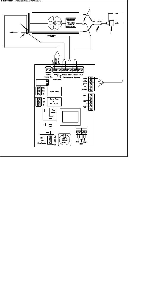
The Master Controller 2.0 is a custom-designed microprocessor-based electronic controller for Master-Bilt® refrigeration products. The controller caple to control an electric expansion valve in response to evaporator superheat and return air temperature. The hardware and input/output descriptions and connections of a Master Controller 2.0 are shown below.
Figure 1 . Master Controller 2.0 Board Layout.
5/16 Rev.B 57-02492 |
6 |

•SEI or SER Terminals. Sporlan SEI and SER type electric expansion valves are currently used for all applications. There are 1596 nominal steps for entire valve stroke.
•Pressure Transducer is mounted at the evaporator suction header to measure saturated suction pressure in absolute value but displayed in gauge pressure in PSIG. The suction pressure is converted to evaporating temperature. The difference between outlet temperature and evaporating temperature is the true superheat displayed as “SUPH”.
•Defrost Termination Temperature Sensor TS3 is mounted downstream of the distributor tube after the valve and close enough to the evaporator coil to measure defrost termination temperature during defrost cylce. Figure 2 on the previous page shows the sensor locations of the evaporator and the controller.
•Outlet/Fan Cut-In Temperature Sensor TS1 is mounted on the suction line about 6” to 10” away from the evaporator to measure outlet temperature during cooling cycle and to serve as evaporator fan cut-in temperature sensor. The
sensor is at a 2 or 10 o’clock position on the suction line. The default value of the fan cut-in temperature is pre-set at 20oF for commercial refrigeration application.
•Room Temperature Sensor TS2 is typically mounted with a plastic tie at the drain pan on the side of the evaporator return air. It is located around the middle of the evaporator to allow even air flow across it. If necessary, it can be relocated to a spot with better representation of the cold room temperature.
•Four Digit LED Display is used to show status of the controller, set point values and temperatures.
•Green Amber and Red LED Status Indicators. The green LED will be on when the compressor relay is energized. The green LED will blink when the air temperature is satisfied, but the compressor minimum run timer or minimum off timer has not yet timed out. The red LED indicates a critical alarm has occurred (Low Pressure alarm). The amber LED indicates all other alarms.
•Six Push Buttons are used to display set points and status as well as to reset operational parameters like room temperature, defrost mode, number of defrosts, etc. Their functions can be also performed by using the TCP/IP interface.
•Two 20 Amp, 240 VAC NC/NO Relays. One relay is used for the defrost heater when the heater load is less than 20 amp. It will be wired to defrost heater contactor when heater load is over 20 amp or three phase heaters. For a reverse cycle defrost system, it is wired to a 40VA transformer that provides 24VAC power to the reversing valve solenoid coil. The other relay is used to switch evaporator fans ON and OFF. A fan contactor will be used if the fan motor is lager than 10 amps or three phase or the voltage is different from control voltage.
•One 3 Amp, 240 VAC NC/NO Relay is used for the compressor contactor or liquid line solenoid.
•One 3 Amp, 240 VAC NC/NO Relay is an option for an external alarm system. The customer can decide what type of a physical alarm is used. This relay is energized when the controller is powered on. Whenever the controller gives an alarm, the relay will be de-energized. For example, a technician can connect a phone alarm system to this relay. When there is an alarm, the alarm system can dial in his pager or cellular phone.
•One RJ-45, TCP/IP Ehternet Port is used for Peer to Peer system or an alternating system communication requiring ethernet connection. It is also used to communicate with a Laptop, internal network, or the internet.
•Power Input 120 or 208/240 VAC. For 120 VAC input, jumper between pins 1 and 2 of ‘Voltage Jumper’ connector and jumper between pins 3 and 4 of ‘Voltage Jumper’ connector. For 208/240 VAC input, jumper between pins 2 and 3 of ‘Voltage Jumper’ connector.
5/16 Rev.B 57-02492 |
7 |
|
|
|
Evap Coil In/ |
|
Evaporator |
|
Defrost Temp. Sensor |
|
|
Liquid Line |
|
|
|
|
|
Pressure |
|
|
|
Transducer |
|
|
|
Suction Line |
|
|
|
|
|
|
Distributor |
|
Room Temp Sensor |
|
Electric |
Evap out / Fan Delay |
|
Expansion |
|
|
|
||
Temp Sensor |
|
|
Valve |
|
T1 |
T2 |
T3 |
ADVANCED MASTER CONTROLLER |
|||
Figure 2.
Factory-Mounted Parts
•A controller board, an Electric/Mechanical expansion valve, a pressure transducer, and three temperature sensors for single evaporator system (standalone or alternating) or peer (multiple evaporator system) evaporator are pre-mounted at the factory. . For a multiple evaporator system, only 1 evaporator is required to have an air temperatue sensor. For reverse cycle defrost, a 24 VAC 40VA transformer is mounted at standalone or master evaporator to provide power 24VAC to the four-way reversing valve mounted in the condensing unit. The control circuit and power supply are pre-wired to the terminal board of the evaporator. The board is molded in epoxy to avoid excessive moisture in cold room.
•A 4-way reversing valve, operating at 24 VAC, is installed in a reverse cycle defrost equipped unit. A transformer is also installed in one of the evaporators to supply 24VAC to the 4-way reversing valve.
•Peer to Peer controls can be connected directly to each other, using a CAT-5E cable, if there are only 2 controllers. The controllers must be connected through an Ethernet switch or router if 3 or more controllers are on the system. The controllers must be bonded together. A technician should install the CAT-5E cable from the controllers to the Ethernet switch or router and bond the controllers. All components are factory tested. A technician should check all the wiring and settings for proper operation after installation.
5/16 Rev.B 57-02492 |
8 |

Features
•One of the most energy-saving features of the Master Controller 2.0 Reverse Cycle Defrost system is free floating head pressure. A head pressure control is not installed on Master Controller 2.0 systems. Without this control, compressors work at the highest efficiency at the lowest possible condensing pressure rather than at the limited pressure level typically found in conventional systems using a head pressure control valve for low ambient environments. For more energy saving information, go to www.masterbilt.com/pdfs/master_controller_vs_standard_system.pdf.
•Option for Mechanical Expansion Valve, or Electronic Expansion Valve
•With the electric expansion valve; the refrigerant flow of the electric expansion valve is modulated by the true superheat, or the difference of evaporator outlet and evaporating temperatures.
•The room temperature sensor replaces the conventional temperature control. The temperature is set with the pushbuttons on the Master Controller 2.0 board or through the web page. The default temperature must be checked during the first startup of the machine against actual application temperature. Default must be re-set to actual application temperature if there is a discrepancy.
•Evaporator Fans cycle during compressor off mode, and options for electric defrost heaters to cycle on-and- off durring defrost for addition energy saving.
•The on-board timer is used for run time control and scheduling defrosts. No mechanical defrost timer is necessary for this system. Once the power is turned on, the timer starts counting.
•The Master Controller 2.0 has the capability to perform scheduled defrost or demand defrost for either Reverse Cycle hot gas defrost, or Electric defrost.
O When the scheduled defrost scheme is chosen, the on-board timer is used for scheduled defrosts. The system works in the same fashion as a regular conventional system with mechanical defrost timer.
O When the demand defrost is chosen, the controller will not initiate a defrost unless it is needed. The low temperature system is pre-set with demand defrost.
•The demand defrost scheme is a pioneer design by Master-Bilt for freezer applications. Extensive lab tests indicate that many unnecessary defrosts are eliminated and energy consumption reduced when using demand defrost compared to using a conventional refrigeration system equipped with a mechanical defrost timer.
•The operational status of modes, room temperature and alarms is displayed on the four-digit on-board display.
•Manual defrost is available on standalone and Peer to Peer systems.
•All components are factory-mounted, pre-wired and tested to save on-site installation labor and reduce chance of installation errors.
•The superheat set point has a wide adjustability range 5° to 20 oF. This range allows the controller to meet different customers’ needs, and require less refrigerant charge for winter operation than conventional refrigeration unit when no head pressure valve is installed in the condensing unit.
•The controller can be used in low, medium and high temperature applications. The internal programming will recognize the input of room temperature set point (RMSP) and automatically select appropriate segments of the program for the application.
•The patented reverse cycle defrost control (United States Patent 7,073,344) reduces defrost energy usage
by up to 80% and decreases defrost time from 20-45 minutes (freezer equipped with electric heaters) to 3-5 minutes in a freezer or 11/2 – 2 minutes in a cooler with a completely clean defrost.
•Maximum operating suction pressure can be controlled by the electric expansion valve eliminating the crankcase pressure regulator for some applications.
•Minimum operating suction pressure provides additional compressor protection.
5/16 Rev.B 57-02492 |
9 |
 Loading...