

Marmitek pro 8 User Manual
IR CONTROL PRO 8
™
ONTROL P
INFRARED EXTENDER SET
USER MANUAL 3
GEBRAUCHSANLEITUNG 9
GUIDE UTILISATEUR 15
MODO DE EMPLEO 21
MANUALE D’ISTRUZIONE 27
GEBRUIKSAANWIJZING 33
20177 / 20080901 • IR CONTROL PRO 8
© ALL RIGHTS RESERVED MARMITEK®2007
TM

2 © MARMITEK

SAFETY WARNINGS
• To prevent short circuits, this product should only be used inside and only in dry spaces.
Do not expose the components to rain or moisture. Do not use the product close to a
bath, swimming pool etc.
• Do not expose the components of your systems to extremely high temperatures or bright
light sources.
•
In case of improper usage or if you have altered and repaired the product yourself, all guarantees
expire. Marmitek does not accept responsibility in the case of improper usage of the product or
when the product is used for purposes other than specified. Marmitek does not accept
responsibility for additional damage other than covered by the legal product responsibility.
• Do not open the product: the device may contain live parts. The product should only be
repaired or serviced by a qualified repairman.
• Only connect the adapter to the mains after checking whether the mains voltage is the
same as the values on the identification tags. Never connect an adapter when it is
damaged. In that case, contact your supplier.
• This product is not a toy. Keep out of reach of children.
ENGLISH
TABLE OF CONTENTS
INTRODUCTION 3
1. OPERATION 3
2. CONTENTS OF THE PACKAGE 4
3. INSTALLATION 4
4. FREQUENTLY ASKED QUESTIONS 6
5. TECHNICAL DATA 7
6. OPTIONAL ACCESSORIES 8
INTRODUCTION
Congratulated on buying the Marmitek Ir Control Pro 8. With it you can extend the IR (infrared) signals of
remote controls. The IR Control Pro 8 makes it possible to control up to 8 A/V devices while these are in a
closed cupboard or when your A/V equipment is out of sight. The IR Control Pro 8 is a universal IR
extender set and is exchangeable with several other IR products of Marmitek and many other makes.
1. OPERATION
The IR receiver of the IR Control Pro 8 receives the signal of your remote control and converts it into an
electric signal which is relayed to the IR module. Up to 8 IR LEDs can be connected to this module. These
IR LEDs make an IR signal of the electrical signal which is received by the IR sensor of your a/V apparatus.
All signals of your remote control are relayed one to one to all connected IR LEDs. If the IR receiver
receives a signal of your remote control it will light up so that you can check the system if it works
properly.
TM
3IR CONTROL PRO 8
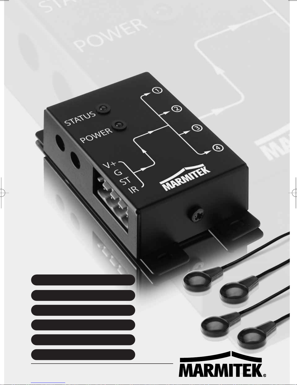
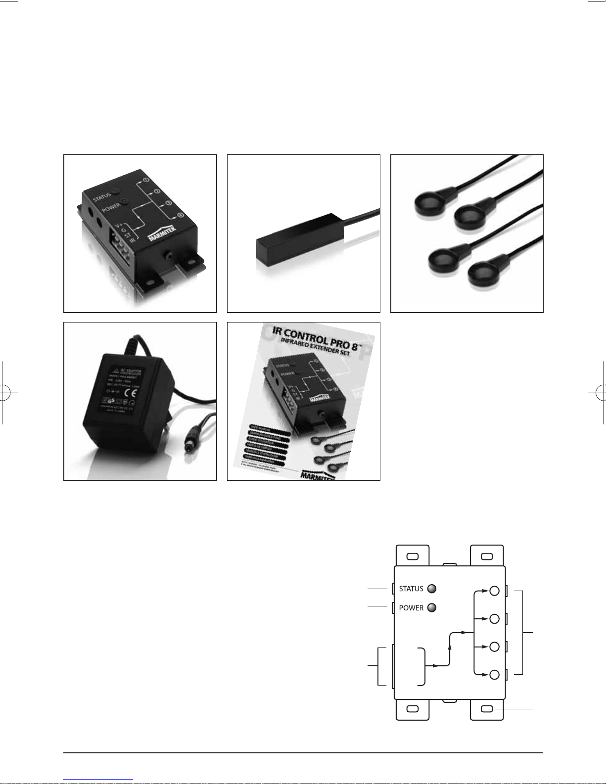
2. CONTENTS OF THE PACKAGE
ABC
DE
3. INSTALLATION
1
2
V+
3
G
ST
IR
1
2
3
4
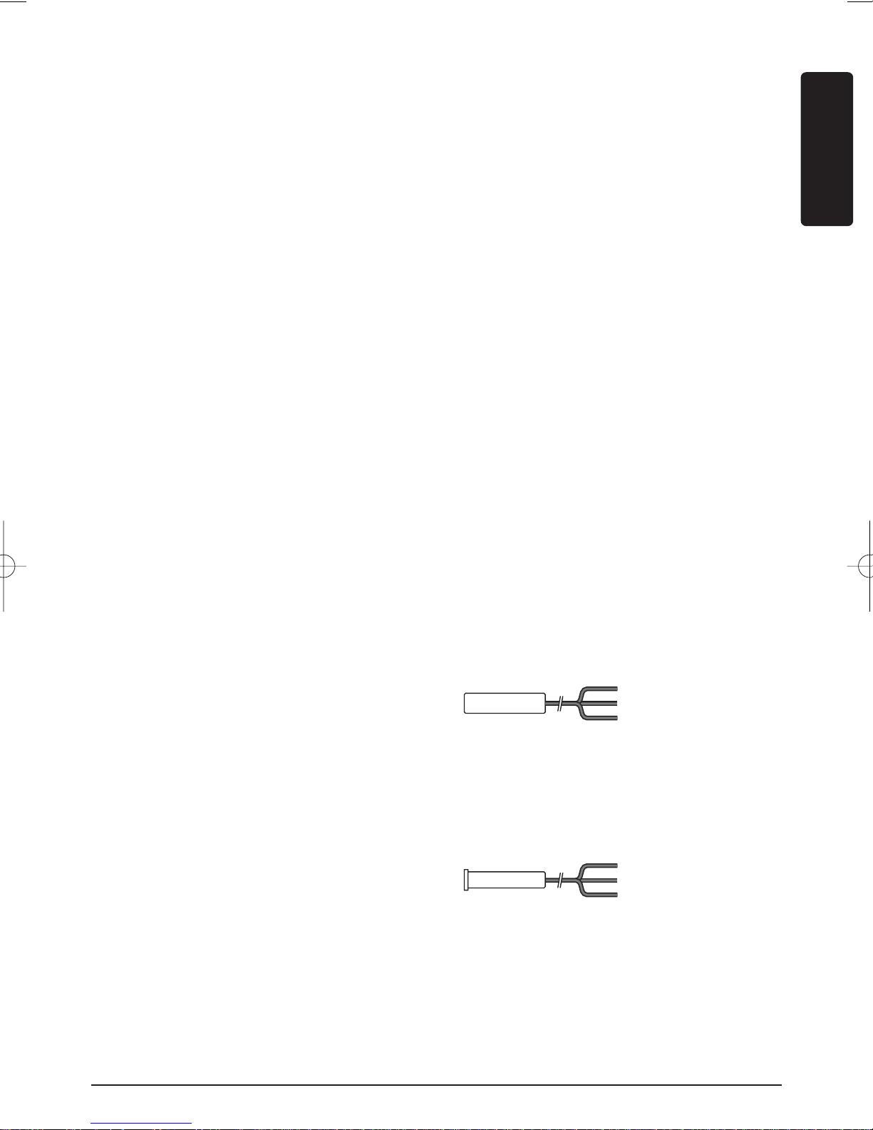
A. 1 x IR Module
B. 1 x IR Receiver
(with connector)
C. 2 x IR Extension cable
with 2 IR LEDs
D. 1 x Power adaptor
E. 1 x Manual
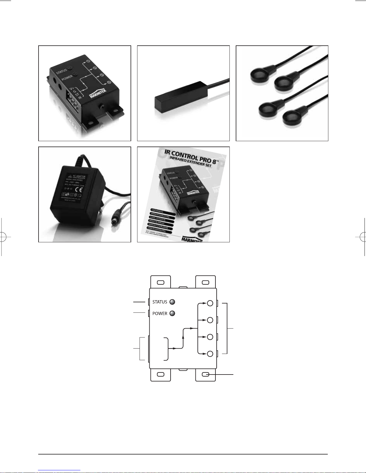
4
1. STATUS Connection for a STATUS power adapter (not supplied)
2. POWER Connection for the POWER power adapter (supplied)
3. (INPUT) Connection for max. 3 IR receiver(s) (1 x supplied)
4. (EMITTERS 1 till 4) Connection for max. 4 IR Extension cables with each 2 IR LEDs.
(2 x supplied)
5. Fastening holes for stable assembling of the IR Module on a smooth underground.
4 © MARMITEK
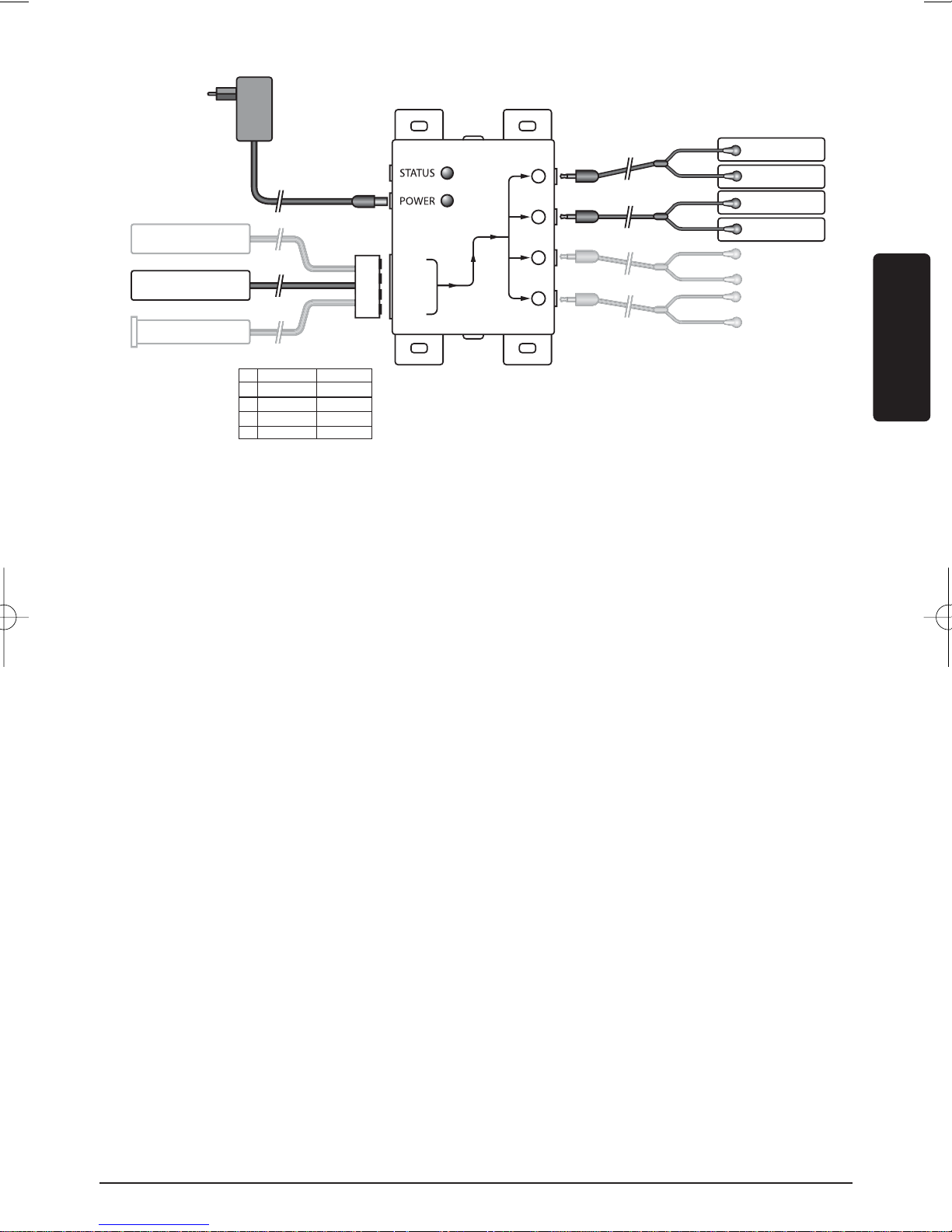
5
Picture 1
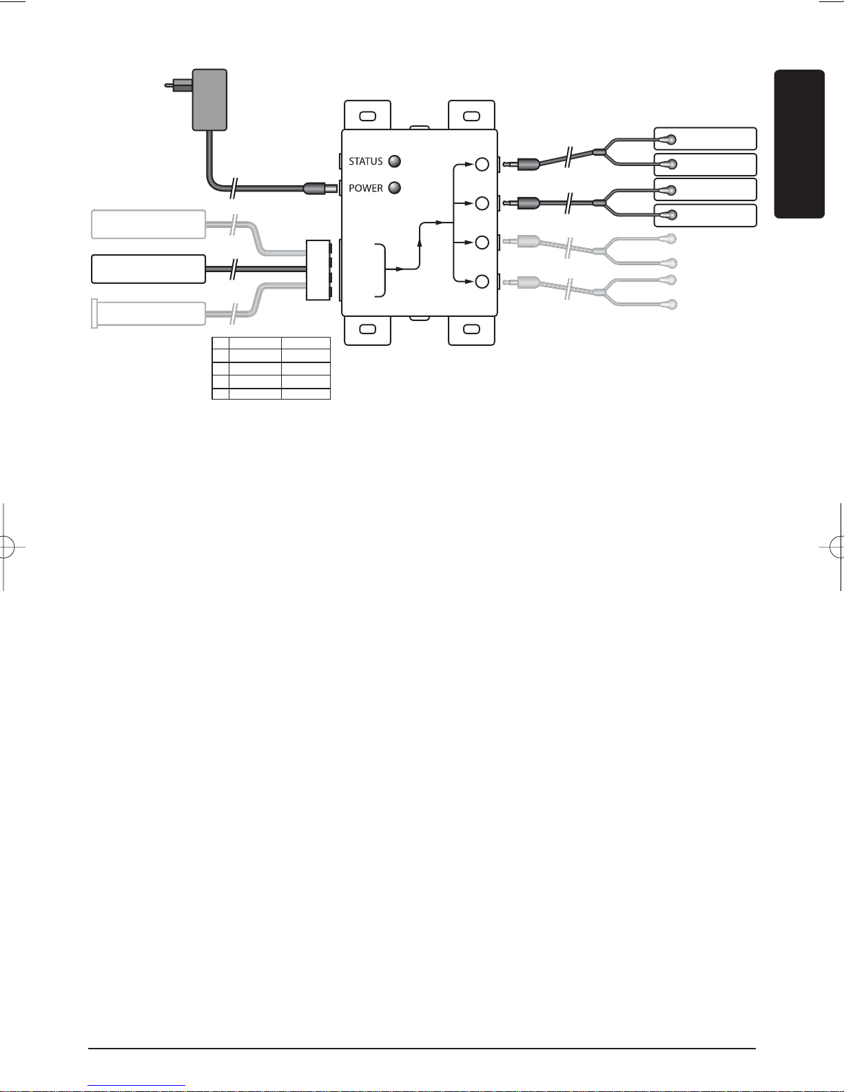
IR Module
IR LEDs
(Max. 4 IR extender cables)
1
ENGLISH
2
V+
3
G
ST
4
IR
IR Receiver
(Max. 3)
09734 09733
V+ Black Black
G Black Black
ST - IR White White
Picture 2
To check the proper working of the system it is advisable first to test the formation as
planned. For this reason connect everything as described as follows but don’t fix or screw the
components yet.
1. Install the IR Module at a place within reach behind or next to your A/V equipment and
near a 230V plug (230Volt/50Hz). Take into account the length of the cable of the IR
LEDs and make sure that the connections are kept accessible if possible.
2.
Plug the required IR Extension cables (with the 2 IR LEDs) into the IR Module (Picture 1 nr. 4).
A self-adhesive foil is supplied with the IR LEDs. With that you can fasten the IR LEDs to
the IR window of your A/V equipment. Note: it’s tricky work. First test the position and
working of the IR LEDs before fixing them permanently to the IR window of your A/V
equipment. Note: If you use only one of the 2 LEDs, then leave the second IR LED
unused. Never remove it from the IR extension cable!
3. Now connect the IR Receiver to the IR Module, for your convenience the connection clip
has been connected to the wiring of the IR Receiver, take care when plugging in of the
correct position (nuts up) and colours of the wiring. When you have to disconnect the
wiring for instance because a connecting clip won’t go through a hole in the furniture,
connect afterwards the wiring to the clip according to the connection scheme in Picture 2.
4. Place the supplied IR receiver in such a way that it is visible for your infrared remote
control and if possible not in the vicinity of potential sources of disturbance like direct sun
light, TL lighting, energy saving lamps etc. The infrared LED indicator on the IR receiver
lights up or flashes when it receives an infrared signal. Use the LED indicator to place the
IR receiver in the place with the least interference (LED indicator is not activated or only
faintly lights up). Because of the supplied self-adhesive strip installation is possible almost
everywhere. Experiment for the correct place before you fix the IR receiver definitively.
Note: The adhesive strip can cause discoloration on certain surfaces or leave glue
remnants by removal.
5. Connect the power adapter to the ‘POWER’ connection of the IR module and plug the
adapter to a wall plug. (230V/50Hz). Check if the ‘POWER’ LED is on.
TM
5IR CONTROL PRO 8
TIP:
• With the help of the supplied IR Extension cables 4 A/V devices can be controlled with
the IR Module, which is simply to be extended to maximal 8 A/V devices with the help of
one ore two optional obtainable IR LEDs. (Art. Nr. 09843).
• With the help of an extra IR Receiver you can also control your A/V equipment from
another place (if desired you can extend the connection cable of the IR receiver.)
- built-in IR receiver Art. nr. 09733
- built-on IR receiver Art. nr. 09734
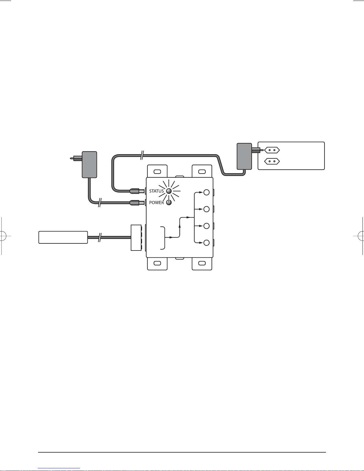
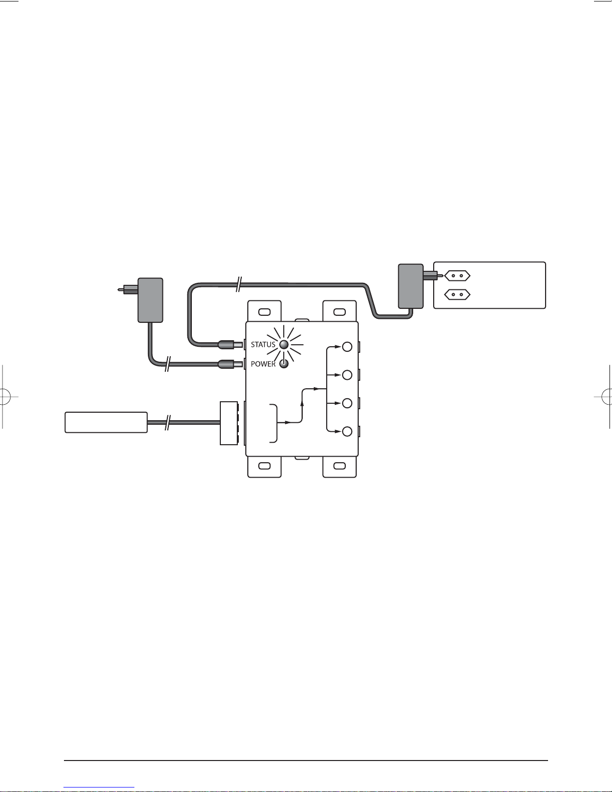
STATUS CONNECTION (Power adapter not supplied)
Power adapter 12V/200mA (optional)
Circuit power on back
of A/V equipment
1
230V/50Hz
2
V+
G
ST
IR
3
4
Picture 3
You can send a Power Status signal to the IR module by connecting a Power adapter to this
connection (not supplied; 12VDC/200mA), which is switched by the device to be controlled.
When the A/V device or contact is switched in a LED will light up in the IR Module so that
you can see that the A/V device is switched in. (see picture 3).
4. FREQUENTLY ASKED QUESTIONS
The IR Receiver does not respond to signals of my remote control.
Observe the following directions:
• Check the connections, is the power adapter connected to the correct connection? This
must be connected to the ‘POWER’ connection, the green lamp will burn when the
power adapter is plugged in the plug.
• Both the built-in and the built-on IR Receiver has a reception sensibility of about 10
metres at an opening Angle of 90 degrees. Range is also dependent on the remote
control used. The IR reception indication LED in the IR Receiver will light up at reception
of an IR signal.
6 © MARMITEK
• The IR Receiver does not work together with some A/V apparatus and models which use
a higher IR frequency like for instance Bang&Olufsen (B&O) .
• Sometimes it may be that the IR Receiver is troubled by so-called interference (direct
sunlight, TL lighting, energy saving lamps etc). In that case you ought to re-direct the IR
Receiver a bit for a better result.
Can I use the IR Receiver near a flat screen TV ?
Yes, sometimes it may happen that the IR receiver suffers some disturbance from the TV
screen. Then move the IR receiver in such a way that it is not in the direct radiation of the TV.
It is easy to test. The infrared LED indicator on the IR receiver lights up or flashes when it
receives an infrared signal. Use the LED indicator to place the IR receiver in the place with the
least interference (LED indicator is not activated or only faintly lights up).
Do you have questions that were not answered in the above mentioned ?
Then look at www.marmitek.com.
5. TECHNICAL DATA
IR Module
Feed POWER: 230VAC/50Hz, 12VC 500mA (supplied).
Feed STATUS: 12VDC 200mA. Plug, - 5.5 mm outside / + 2.1 mm
inside (not supplied).
IR LEDs connections: 4 x 3.5 mm jack plug (mono).
IR Receiver connection: 1 Connector for maximal 3 parallel connected receivers.
Dimensions: 85x49x24xmm (fastening points inclusive).
ENGLISH
IR receiver built-on
Frequency range: 30-100 KHz.
IR reception range: ± 10 metres.
G:
V+:
IR:
Black
Black
White
Length of cable: 2 metres, extendable to max 300 metres (UTP or equivalent).
IR receiver: Reception indication LED.
IR reception angle: 90° (+45°/-45° from centre).
Dimensions receiver bloc: 51x10x8mm.
IR receiver built-in (optional)
Frequency range: 30-100 KHz.
IR reception range: ± 10 metres
G:
V+:
IR:
Black
Black
White
Length of cable: 2 metres, extendable to max 300 metres (UTP or equivalent).
IR receiver: Reception indication LED.
IR reception angle: 90°(+45°/-45° from centre)
Dimensions receiver: Diameter 11.7 mm - Drilling size 12 mm - Length 50 mm
Built-in depth 55 mm - Maximal thickness of material 40 mm.
TM
7IR CONTROL PRO 8
IR Extension cable
Connection: 3.5mm jack plug
IR LEDs: 2x IR LED
Length of cable: 3 metres (from plug to division 2m, from division to LED 1m).
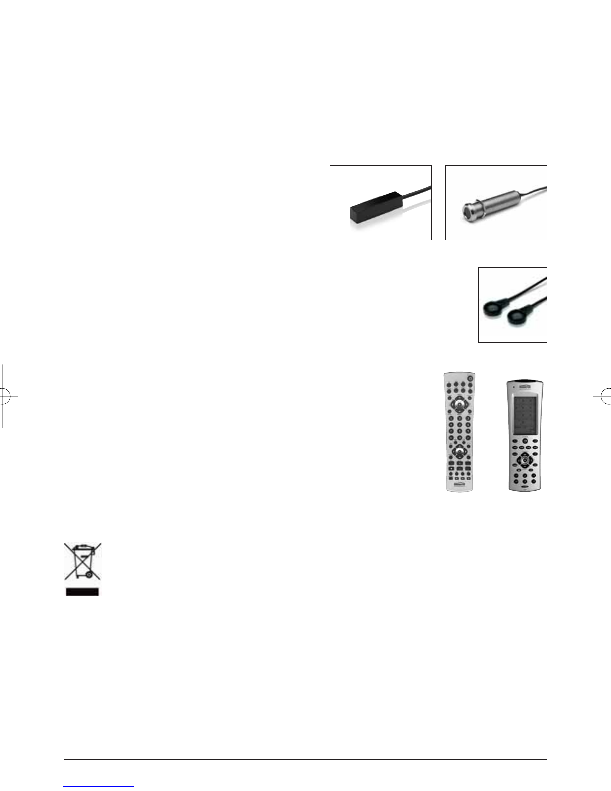
6. OPTIONAL ACCESSORIES
Extra IR receiver
Built-on Art.nr. : 09734
Panel Mount Art.nr.: 09733
With the help of an extra IR Receiver you can also
operate your A/V from another room. See for
more information www.marmitek.com.
09734
Extra IR Extension cable Art.nr.: 09843
With the help of an extra IR extension cable you can operate 2 extra A/V
devices. (Extendable to maximal 8 A/V apparatus). See for more information
www.marmitek.com.
09733
09843
Marmitek EasyControl8™ Art.nr.: 09662
Marmitek EasyTouch35™ Art.nr.: 09664
With both universal remote controls you can control 8 A/V devices:
TV, video, DVD, cable, satellite, audio, Marmitek X10 and digital
satellite. Through pre-programmed codes and learner function they
work always. The EasyTouch35™ is provided with a convenient
Touchscreen with pale blue screen lighting. See for more information
www.marmitek.com.
Environmental Information for Customers in the European Union
European Directive 2002/96/EC requires that the equipment bearing this symbol on the pr oduct and/or its packaging
must not be disposed of with unsorted municipal waste. The symbol indicates that this product should be disposed
of separately from regular household waste streams. It is your responsibility to dispose of this and other electric and
electronic equipment via designated collection facilities appointed by the government or local authorities. Correct
disposal and recycling will help prevent potential negative consequences to the environment and human health. For more
detailed information about the disposal of your old equipment, please contact your local authorities, waste disposal service, or
the shop where you purchased the product.
0966409662
8 © MARMITEK

SICHERHEITSHINWEISE
• Um Kurzschluss vorzubeugen, dieses Produkt bitte ausschließlich innerhalb des Hauses und nur in
trockenen Räumen nutzen. Setzen Sie die Komponenten nicht Regen oder Feuchtigkeit aus. Nicht
neben oder nahe eines Bades, Schwimmbades usw. verwenden.
• Setzen Sie die Komponente Ihres Systems nicht extrem hohen Temperaturen oder starken
Lichtquellen aus.
• Bei einer zweckwidrigen Verwendung, selbst angebrachten Veränderungen oder selbst
ausgeführten Reparaturen verfallen alle Garantiebestimmungen. Marmitek übernimmt bei einer
falschen Verwendung des Produkts oder bei einer anderen Verwendung des Produktes als für den
vorgesehenen Zweck keinerlei Produkthaftung. Marmitek übernimmt für Folgeschäden keine
andere Haftung als die gesetzliche Produkthaftung.
• Dieses Produkt ist kein Spielzeug. Außer Reichweite von Kindern halten.
• Das Produkt niemals öffnen (ausgen.des Batteriefachs): Das Gerät kann Teile enthalten, worauf
lebensgefährliche Stromspannung steht. Überlassen Sie Reparaturen oder Wartung nur Fachleuten.
• Schließen Sie den Netzadapter erst dann an das Stromnetz an, nachdem Sie überprüft haben, ob
die Netzspannung mit dem auf dem Typenschild angegeben Wert übereinstimmt. Schließen Sie
niemals einen Netzadapter an, wenn diese beschädigt sind. In diesem Fall nehmen Sie Kontakt mit
Ihrem Lieferanten auf.
DEUTSCH
INHALTSANGABE
EINFÜHRUNG 9
1. BETRIEB 9
2. VERPACKUNGSINHALT 10
3. INSTALLATION 10
4. HÄUFIG GESTELLTE FRAGEN 12
5. TECHNISCHE DATEN 13
6. OPTIONAL ERHÄLTLICH 14
EINFÜHRUNG
Herzlichen Glückwunsch zum Erwerb des Marmitek IR Control Pro 8™. Mit diesem Set können
Sie IR (Infrarot-) Signale von Fernbedienungen verlängern. Das IR Control Pro 8™ Set ermöglicht
es, bis zu 8 A/V Geräte zu bedienen, während diese sich in einem geschlossenen Schrank oder
außer Sichtweite befinden. Das IR Control Pro 8™ ist ein universelles IR Verlängerungsset und mit
verschiedenen anderen Marmitek® IR Produkten und vielen anderen Marken austauschbar.
1. BETRIEB
Der IR Empfänger des IR Control Pro 8™ Sets empfängt das Signal Ihrer Fernbedienung und setzt
dieses in ein elektrisches Signal um, das an das IR Modul weitergegeben wird. An dieses Modul
können bis zu 8 IR LED angeschlossen werden. Diese IR LED wandeln das elektrische Signal wieder in
ein IR Signal um, was von dem IR Sensor Ihres A/V Geräts empfangen wird. Alle Signale Ihrer
TM
9IR CONTROL PRO 8
Fernbedienung werden eins zu eins an alle angeschlossenen IR LED weitergegeben. Wenn der IR
Empfänger ein IR Signal Ihrer Fernbedienung empfängt, so wird diese aufleuchten sodass Sie das
System auf korrekten Betrieb kontrollieren können.
2. VERPACKUNGSINHALT
ABC
DE
3. INSTALLATION
1. STATUS
Anschluss für einen STATUS Speisungsadapter
(nicht mitgeliefert).
2. POWER
Anschluss für den POWER Speisungsadapter
(mitgeliefert).
3. (INPUT)
Anschluss für max. 3 IR Empfänger (1x
mitgeliefert).
4. (EMITTERS 1 t/m 4)
Anschluss für max. 4 IR Verlängerungskabel mit
je 2 IR LED, (2x mit enthalten).
5. Befestigungslöcher für eine stabile Montage
des IR Moduls auf einem flachen Untergrund.
1
2
3
A 1x IR Modul
B 1x IR Empfänger
(mit Connector)
C 2x IR Verlängerungskabel
mit 2 IR LED
D 1x Speisungsadapter
E 1x Gebrauchsanleitung
IR Modul
1
2
V+
G
ST
IR
3
4
Abbildung 1
4
5
10 © MARMITEK
IR Modul
IR LED
(Max. 4 IR-Verlängerungskabels)
1
2
3
4
Abbildung 2
IR Empfänger
(Max. 3)
V+
G
ST
IR
09734 09733
V+ Schwarz Schwarz
G Schwarz Schwarz
ST - IR Weiß Weiß
Zur Kontrolle des korrekten Systembetriebs empfehlen wir, die von Ihnen geplante Aufstellung
zunächst zu testen. Schließen Sie dazu alles an, wie im Nachfolgenden umschrieben, kleben oder
schrauben Sie die Komponenten jedoch noch nicht fest.
1. Montieren Sie das IR Modul an einen erreichbaren Ort hinter oder neben Ihren A/V Geräten und
nahe einer 230V Steckdose (230Volt/50Hz). Berücksichtigen Sie die Kabellänger der IR LED und
achten Sie darauf, dass die Anschlüsse möglichst erreichbar bleiben.
2. Stecken Sie die benötigten IR Verlängerungskabel (mit den 2 IR LED) in das IR Modul (Abbildung
1 Nr. 4). Zu den IR LED ist eine selbstklebende Folie mitgeliefert. Hiermit können Sie die IR LED an
das IR Fenster Ihres A/V Geräts befestigen. Achtung: dies erfordert große Genauigkeit. Testen Sie
zunächst die Position und den Betrieb der IR LED, bevor Sie diese definitiv an das IR Fenster Ihres
A/V Geräts festkleben.
ACHTUNG: Wenn Sie Sie nur einen der 2 LED verwenden, lassen Sie dann den zweiten IR LED
ungebraucht. Entfernen Sie diesen niemals vom IR Verlängerungskabel!
3.
Schließen Sie nun den IR Empfänger an das IR Modul an. Die Anschlussklemme ist, um Ihnen die
Arbeit zu erleichtern, bereits an die Drähte des IR Empfängers befestigt. Achten Sie beim Einstecken
auf die richtige Position (Schrauben oben) und auf die Farben der Drähte. Wenn Sie die Drähte lösen
müssen, weil z.B. die Anschlussklemme nicht durch die Öffnung des Möbelstücks passt, schließen
Sie dann die Drähte wieder gemäß dem Anschlussschema in Abbildung 2 an die Klemme an.
4. Bringen Sie den mitgelieferten IR Empfänger so an, dass dieser in Sichtkontakt zu Ihrer InfrarotFernbedienung steht und sich möglichst weit entfernt von eventuellen Störquellen wie direkt
einfallendes Sonnenlicht, TL Beleuchtung, Sparlampen, usw. befindet. Die Infrarot LED Anzeige
am IR Empfänger leuchtet auf oder blinkt, wenn diese Infrarotstrahlung empfängt. Verwenden Sie
diese LED Anzeige, um den IR Empfänger an einer störungsfreien Stelle anzubringen (LED wird
nicht oder kaum ansprechen). Durch den mitgelieferten, selbstklebenden Klebestreifen ist
Anbringung nahezu überall möglich. Experimentieren Sie zur Feststellung des richtigen Platzes,
bevor Sie den IR-Empfänger definitiv festkleben. Achtung! Der Klebestreifen kann auf bestimmten
Oberflächen zu Verfärbungen führen oder bei Entfernung Leimreste hinterlassen.
5.
Schließen Sie den Speisungsadapter an den “POWER” Anschluss Ihres IR Moduls an und stecken Sie
den Adapter in eine Steckdose (230V/50Hz). Überprüfen Sie, ob die “POWER” LED eingeschaltet ist.
DEUTSCH
DEUTSCH
TM
11IR CONTROL PRO 8
TIPP:
• Mit dem IR Modul können mithilfe des mitgelieferten IR Verlängerungskabels 4 A/V
Geräte bedient werden. Diese können mit 1 oder 2 optional erhältlichem IR LEDs
kinderlicht auf bis zu max. 8 A/V Geräte erweitert werden, (Art.-Nr. 09843).
• Mithilfe eines zusätzlichen IR Empfängers können Sie Ihre A/V Geräte auch von einem
anderen Ort aus bedienen (Sie können dazu den Anschlussdraht des IR Empfängers nach
Wunsch verlängern).
- Einbau IR Empfänger Art.-Nr. 09733
- Aufbau IR Empfänger Art.-Nr. 09734
STATUS ANSCHLUSS (Speisungsadapter nicht im Lieferumfang enthalten)
Speisungsadapter 12V 200mA (optional)
Geschaltete Speisung auf
Rückseite des A/V Geräts
1
230V/50Hz
2
V+
G
ST
IR
3
4
Abbildung 3
Sie können ein Power Status Signal zum IR Modul senden, indem Sie an diesen Anschluss
einen Speisungsadapter anschließen (nicht mitgeliefert; 12VDC/200mA), der vom zu
bedienenden Gerät geschaltet wird. Wenn das A/V Gerät oder der Kontakt eingeschaltet ist,
wird ein LED am IR Modul aufleuchten, sodass Sie sehen können, dass das A/V Gerät
eingeschaltet ist (siehe Abbildung 3).
4. HÄUFIG GESTELLTE FRAGEN
Der IR Empfänger reagiert nicht auf Signale meiner Fernbedienung.
Beachten Sie nachfolgende Hinweise:
• Überprüfen Sie die Anschlüsse. Ist der Speisungsadapter an den richtigen Eingang
angeschlossen? Dieser muss an den “POWER” Anschluss angeschlossen werden. Das
grüne Lämpchen wird aufleuchten, wenn der Speisungsadapter an die Steckdose
angeschlossen ist.
• Sowohl der Einbau- wie auch der Aufbau- IR Empfänger besitzt eine
Empfangsempfindlichkeit von ca. 10 Metern, bei einem Öffnungswinkel von 90 Grad.
12 © MARMITEK
 Loading...