

Marmitek PGI850 Installation Manual
The ProGuard Interphone provides the ProGuard control panel with an external
microphone and speaker for Two-Way Audio applications.
Installation
Pry-off
l
Speaker
Volume
Trimme
r
Power LED
To install the ProGuard Interphone:
1. Remove the two cover screws.
2. Lift the front cover away from the base.
3. a 2.5m cable with a 6-position RJ-11 connector is supplied
with the ProGuard Interphone. This cable can be spliced to a
24AWG solid four-core cable.
4. Thread the cable through the wiring hole on the back cover.
5. Mount the back cover to the wall using four mounting
screws.
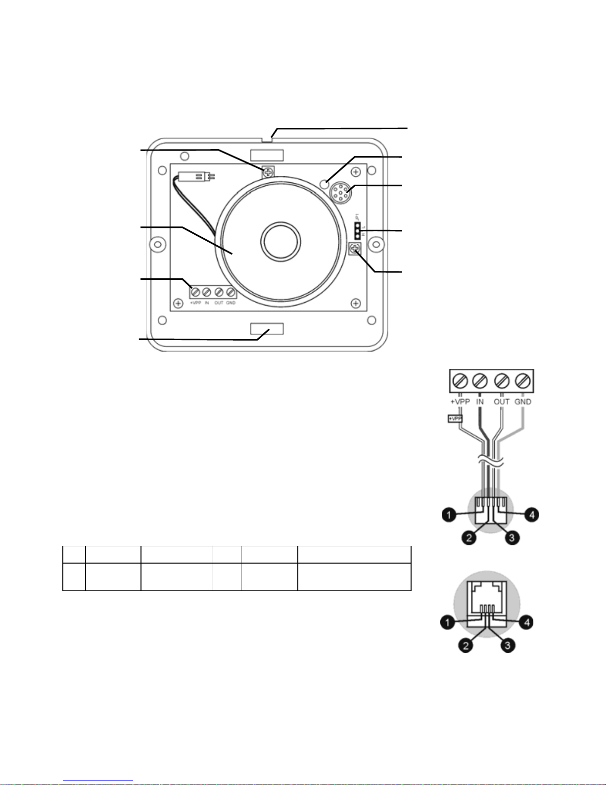
6. Connect the cable to the terminal block on the ProGuard
Interphone as follows:
¬
[White] +VPP
®
[White] OUT (microphone)
[Blue]
IN
(speaker)
¯
[Orange] GND
Note: The +VPP wire is labeled for convenience
7. Plug the cable into the RJ-11 jack on the ProGuard Main board.
8. Replace the front cover and secure using the two cover screws.
Terminal
Block
Microphone
Microphone
Sensitivity
Jum
p
er
Speake
r
Microphone
Sensitivity
Trimm
r
Wiring
Hole
ProGuard Interphone
ProGuard MAIN BOARD
6-Position
RJ-11
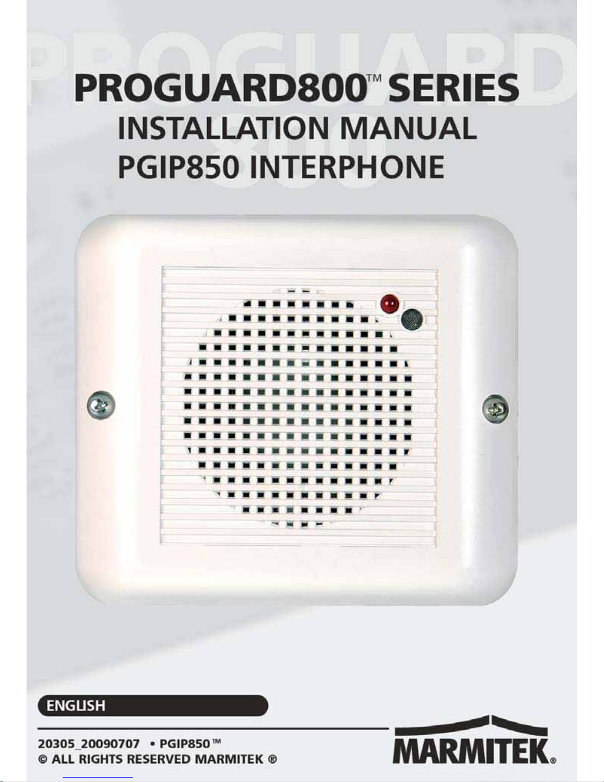
Figure 2: Wiring
Connections
Figure 1: ProGuard Interphone (cover off)
© MARMITEK 2
 Loading...