

Marmitek PC to TV SENDER Owner's Manual

C to TV SENDE
PC to TV SENDER
OWNER’S MANUAL 3
BETRIEBSANLEITUNG 7
MODE D’EMPLOI 11
GEBRUIKSAANWIJZING 15
20035 / 20060602 MARMITEK ALL RIGHTS RESERVED
PC to TV SENDER
J
H
J
K
A
B
A
I
IE FC DDE
K
B
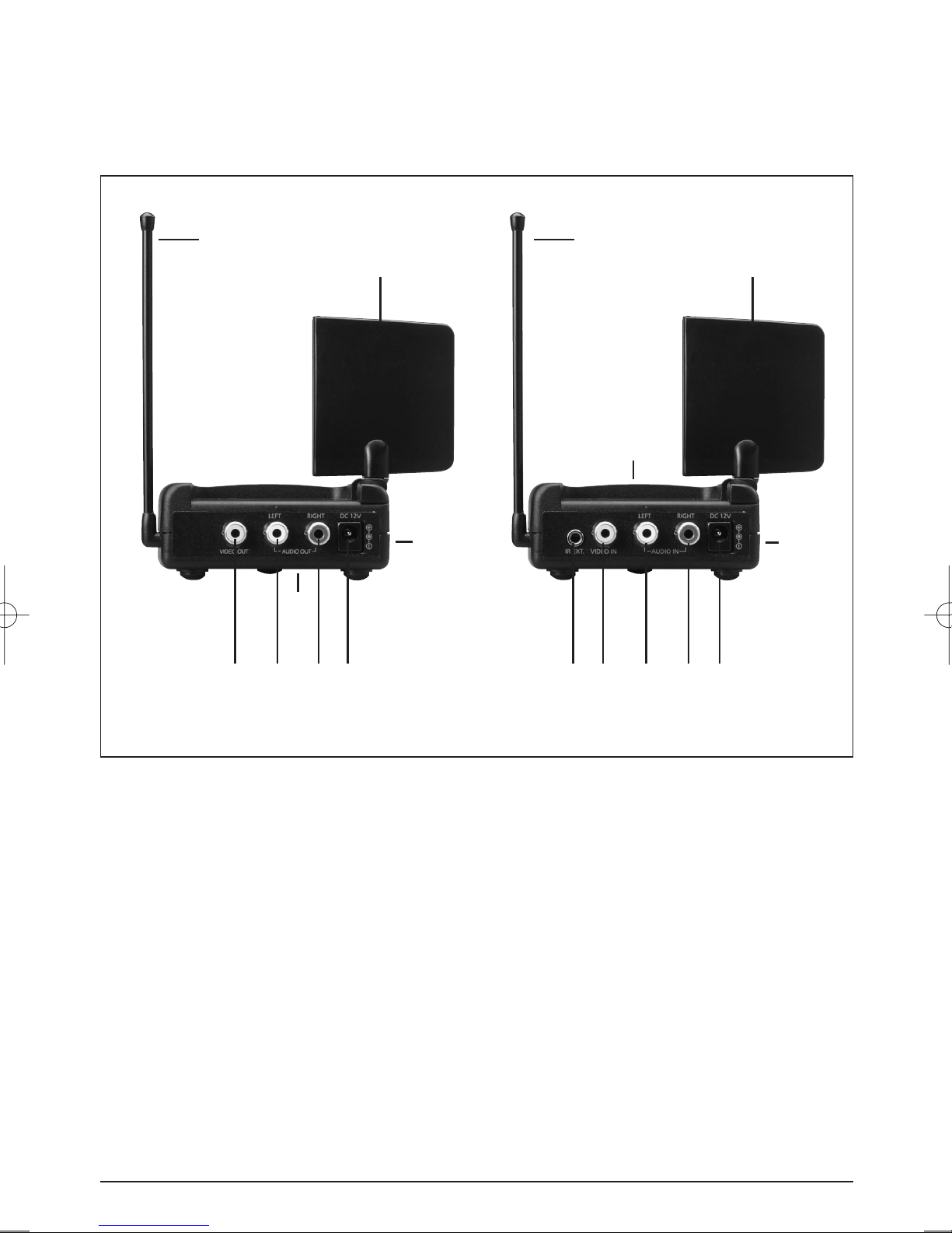
GV20 TransmitterGV20 Receiver
2 MARMITEK

MARMITEK GV20 PC to TV SENDER
OWNER’S MANUAL
READ THIS FIRST!
Caution: to reduce risk of electric shock, do not disassemble any part of the videosender
system. No user-serviceable parts are inside. If you spill liquid on it, disconnect the unit from
the AC outlet to prevent possible fire or shock hazard and consult authorized service
personnel.
Use only the supplied powersupplies. Defective parts must be replaced by original spareparts
only.
Powerline operated equipment or accessories connected to the unit should bear the CE
certification mark and should not be modified in any way that might defeat the safety
features.
Warning: to prevent electric shock hazard, do not expose any part of the video Sender to
rain or moisture. Do not use near a bath tub, swimmingpool, etc. Disconnect the unit during
thunderstorms from mains and other connected equipment to avoid damage.
No guarantee or liability will be accepted for any damage caused due to incorrect use of the
equipment supplied, other than indicated in this owner’s manual.
1. SETTING UP THE MARMITEK GV20 TRANSMITTER
1. Connect one set of Audio/Video cables to the VIDEO [C] and AUDIO [D] jacks of your
Marmitek GV20 Transmitter. Take care to match the colors of the plugs on the cable
with the jacks on the GV20 Transmitter.
2. Connect the other end of the cable to the Audio/Video OUT jacks of the video source you
want to transmit the signal from (e.g. your VCR, DVD, Satellite or TV). If your video source
is equipped with a SCART connector use the SCART Adapter labelled TRANSMITTER. If the
jacks are colored differently, connect the yellow plug on the jack VIDEO, the red plug on
the jack AUDIO RIGHT and the white plug to the jack AUDIO LEFT.
3. Switch the Power slide switch on the side into the "OFF" position
4. Plug the supplied mains adaptor, labelled Sender/Transmitter 12V, 200mA, into a 230Volt
50Hz wall outlet and connect the jack to the 12V jack at the rear side of the transmitter.
Only use the supplied mains adaptor!
5. Switch the Power switch to the ON position.
6. Set the Channel-switch [A] on A.
7. Position the transmitter in a convenient location and orient the antenna [K]
PC TO TV SENDER
3
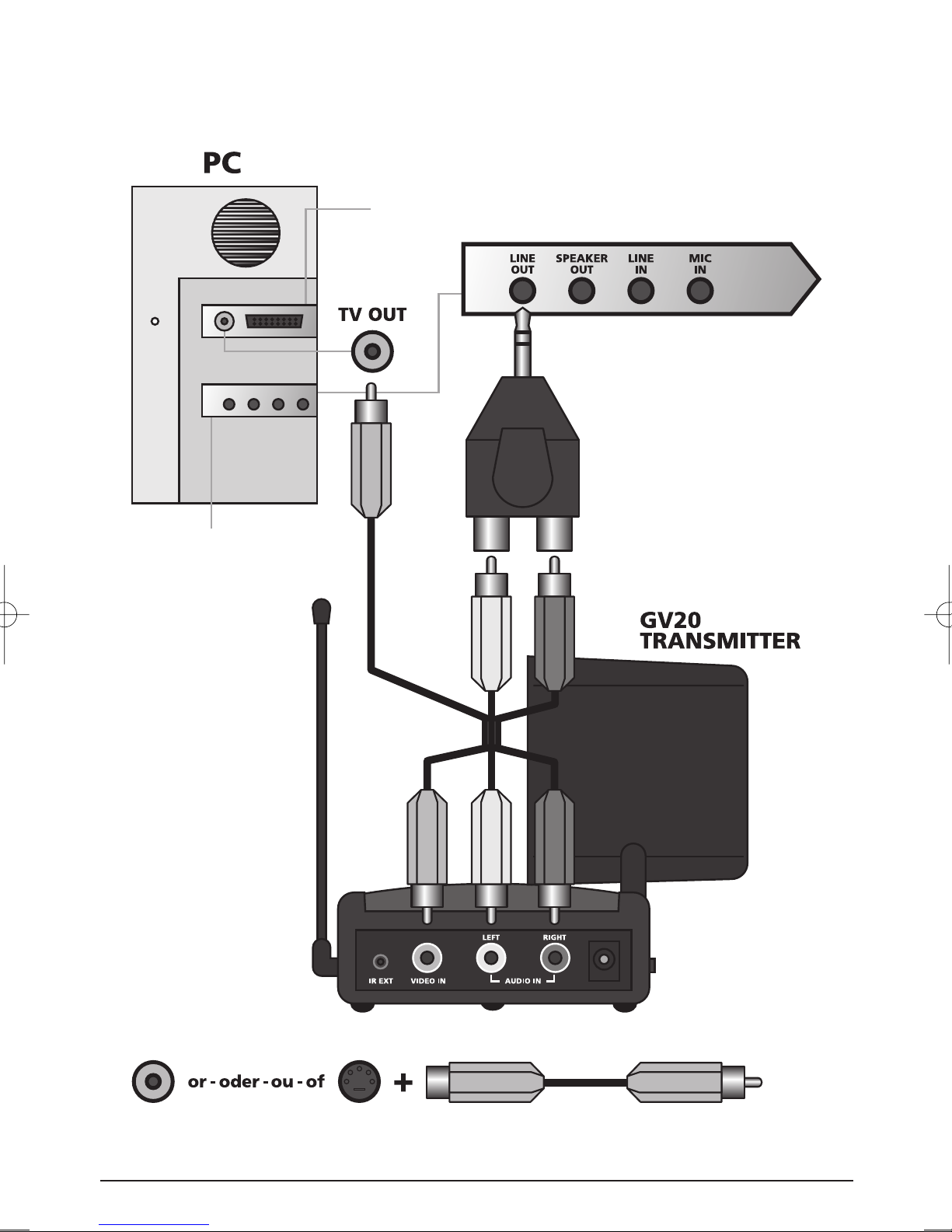
To connect the GV20 transmitter to your PC, please refer
to the schematic below.
Video card
Yellow
Sound card
RedWhite
RCA
Yellow
4 MARMITEK
SVIDEO
WhiteYellow
Red
RCA
Provided with your Video Card or use Marmitek
CVBS conversion cable, Art. No. 09388
If you have several A/V components:
If you have two or more A/V components (e.g. VCR, Cable box, Laserdisc or satellite receiver)
that you want to watch in another room, they will probably already been hooked up to the
local TV in series. To connect the GV20 Transmitter you just need to indentify the last
component in the chain and connect the Line OUT or scart to the GV20 Transmitter IN jacks.
2. SETTING UP THE MARMITEK GV20 RECEIVER
1. Connect a set of Audio/Video cables to the LINE OUT jacks [H+I] of your GV20 Receiver.
Connect the other end to your TV. If your TV has a Scart connector, you may use the
Scart adaptor provided; labelled: "Receiver".
2. Switch the Power slide switch on the side into the "OFF" position
3. Plug the supplied mains adaptor, labelled Receiver 9V, 400mA, into a 230Volt -50Hz wall
outlet and connect the jack [E] to the 9V jack at the backside of the receiver. Only use the
supplied mains adaptor!
4. Switch the Power switch [B] to the ON position.
5. Set the Channel-switch [A] on A.
6. Put the side antenna [J] of the remote control extender in an upright position.
3. FINE TUNING YOUR MARMITEK GV20 SET
Make sure your A/V equipment is switched on. Switch the receiving TV on and select the A/V
channel (normally found on the "0" or "AV" button). The picture should now automatically
be there, no tuning is required.
The wireless GV20 usually works best with the indented faces of the antennas [K] on the
Transmitter and Receiver unit look at one another. Sometimes however distance, reflections
and other effects in the home may affect the signal so that some adjustment of either
Transmitter or Receiver antenna may be necessary to get the best signal.
If still experiencing difficulty, try changing the "ABCD" channel selector and change channels.
Remember though both the receiver and transmitter must be on the same channel.
If you are not getting any signal at all:
Check that the units are connected to mains and that the Power-switch is in the ON position.
Check that the Channel slide switch (labelled A-D) on both GV20 units is set at the same
number. Check if the receiving TV is on the correct A/V channel. Raise the small black side
antenna [J] to an upright position.
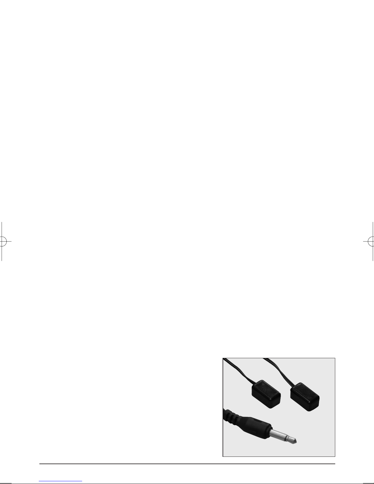
4. THE REMOTE EXTENDER
FEATURE
To use this feature, you need the
Marmitek IR Eye, separately available
(Art. No. 09682)
Your Marmitek VideoSender has the ability to transmit
infrared signals from your own remote control from
your receiving TV back to the equipment connected to
videosender. For example, you can change channels on
PC TO TV SENDER
Marmitek
art.no. 09682
5

your satellite receiver while viewing in another room. Simply point your original remote
control to the IR window on the front of your GV20 Receiver. The IR signal is now transmitted
by radio to the GV20 transmitter.
Set up is simple, ideally with 2 people. Use the “IR Eye” IR LED (optional) and connect the
small jack plug on the back of the Transmitter (IR)
You have to place the IR LED (emitter) in front of the IR sensor of the equipment you want to
control. For the best result you can experiment which position of the IR LED (emitter) works
best.
If you have problems with the range, try to move the receiver and/or transmitter away from
your connected equipment. This can greatly increase performance of the radio transmission.
Copyright © Marmitek. The right is reserved to make technical modifications
6 MARMITEK
 Loading...