

Marantz ST-17-2 Sevice Bulletin
SERVICE BULLETIN
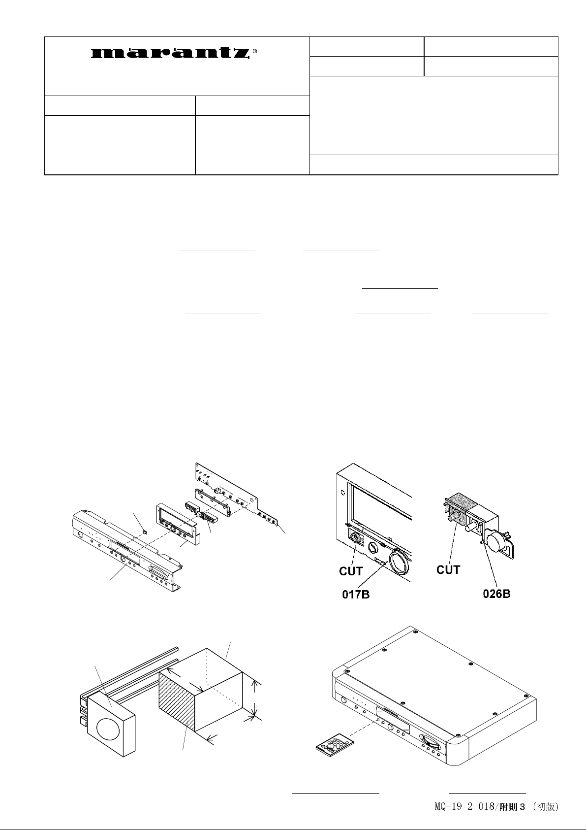
Fig. 2
Fig. 1
Fig. 4
Fig. 3
Date: 6-Nov-98 Model: 74ST17/02B/02G
Page: 1/1 REF.NB MZ98-030
Subject:
Circulation: Application:
Remote control modification.
x for information
customer complaint
in case of service
mandatory
...................
[
SOLUTION
]
Only required case from a
customer.
Int.ref:
Modify the front panel assembly as following procedure.
1.
Disassemble the front panel assembly from the p rodu ct and re move 017B, 026B and PCB PS02 fr om the
front panel (002B). (Fig .1)
2.
Add the IR lens (013B:
to the hole of PTY button on the front panel. (Fig.1)
3.
Cut the PTY button and the bu tto n g uid e . (Fig . 2 : Gr ay p art)
4.
Remove the tact switch (SS24). And add the IR sensor (QS03:
(13x10x10). (Fig. 3)
5.
Add diodes DS03, DS04 (
resistors RS63 (
7 and page 9)
6.
Reassemble the front p ane l. (Fig . 1 & 4)
7.
Press POWER switch while depressing
then modification had succeed.
•
Every MARANTZ remote control units which including TUNER mode are available for command
transmit.
180 ohm
4822 381 12024
4822 130 32362
1/6W), RS65 (
[/02B] or
), transistors QS04 (
10K ohm
DISPLAY
4822 381 12025
1/6W). (refer the serv ice manu al 4822 725 51167 page
button and
(Add IR sensor for remote operation.)
[/02G]) with dual side adhesive tape
4822 130 11494
4822 130 61227
BAND
, if FL display shows <
) with the formed rubbe r
), QS05 (
4822 130 42594
RC INT
),
>
[
REMARK
This information is applied to Europe, Africa and Middle East only.
available after this modification.
]
002B
013B
026B
017B
Dual side adhesive tape
PS02
QS03
10
Rubber
10
“
” function is not
PTY
13mm
Dual side adhesive tape
Approved by C. Miyayama
Written by H. Tamura
 Loading...