

Page 1

ENGLISHFRANÇAISDEUTSCHNEDERLANDSITALIANO
8 Channel Power Amplifier
MM8003
Page 2

ENGLISH
DEUTSCH
ITALIANO
WARRANTY
For warranty information, contact your local Marantz
distributor.
RETAIN YOUR PURCHASE RECEIPT
Your purchase receipt is your permanent record of a
valuable purchase. It should be kept in a safe place
to be referred to as necessary for insurance purposes
or when corresponding with Marantz.
IMPORTANT
When seeking warranty service, it is the responsibility of
the consumer to establish proof and date of purchase.
Your purchase receipt or invoice is adequate for such
proof.
FOR U.K. ONLY
This undertaking is in addition to a consumer's
statutory rights and does not affect those rights in
any way.
FRANÇAIS
GARANTIE
Pour des informations sur la garantie, contacter le
distributeur local Marantz.
CONSERVER L'ATTESTATION D'ACHAT
L'attestation d'achat est la preuve permanente
d'un achat de valeur. La conserver en lieu sur pour
s'y reporter aux fi ns d'obtention d'une couverture
d'assurance ou dans le cadre de correspondances
avec Marantz.
IMPORTANT
Pour l'obtention d'un service couvert par la garantie,
il incombe au client d'établir la preuve de l'achat
et d'en corroborer la date. Le reçu ou la facture
constituent des preuves suffi santes.
GARANTIE
Bei Garantiefragen wenden Sie sich bitte an Ihren
Marantz-Händler.
HEBEN SIE IHRE QUITTING GUT AUF
Die Quittung dient Ihnen als bleibende Unterlage
für Ihren wertvollen Einkauf Das Aufbewahren der
Quittung ist wichtig, da die darin enthaltenen Angaben
für Versicherungswecke oder bei Korrespondenz mit
Marantz angeführt werden müssen.
WICHTIG!
Bei Garantiefragen muß der Kunde eine Kaufunterlage
mit Kaufdatum vorlegen. Ihren Quittung oder
Rechnung ist als Unterlage ausreichend.
NEDERLANDS
GARANTIE
Voor inlichtingen omtrent garantie dient u zich tot uw
plaatselijke Marantz.
UW KWITANTIE, KASSABON E.D. BEWAREN
Uw kwitantie, kassabon e.d. vormen uw bewijs van
aankoop van een waardevol artikel en dienen op een
veilige plaats bewaard te worden voor evt, verwijzing
bijv, in verbend met verzekering of bij correspondentie
met Marantz.
BELANGRIJK
Bij een evt, beroep op de garantie is het de
verantwoordelijkheid van de consument een
gedateerd bewijs van aankoop te tonen. Uw
kassabon of factuurzijn voldoende bewijs.
GARANZIA
L’apparecchio è coperto da una garanzia di buon
funzionamento della durata di un anno, o del periodo
previsto dalla legge, a partire dalla data di acquisto
comprovata da un documento attestante il nominativo
del Rivenditore e la data di vendita. La garanzia sarà
prestata con la sostituzione o la riparazione gratuita
delle parti difettose.
Non sono coperti da garanzia difetti derivanti da
uso improprio, errata installazione, manutenzione
effettuata da personale non autorizzato o, comunque,
da circostanze che non possano riferirsi a difetti di
funzionamento dell’apparecchio. Sono inoltre esclusi
dalla garanzia gli interventi inerenti l’installazione e
l’allacciamento agli impianti di alimentazione.
Gli apparecchi verranno riparati presso i nostri Centri
di Assistenza Autorizzati. Le spese ed i rischi di
trasporto sono a carico del cliente.
La casa costruttrice declina ogni responsabilità per
danni diretti o indiretti provocati dalla inosservanza
delle prescrizioni di installazione, uso e manutenzione
dettagliate nel presente manuale o per guasti dovuti ad
uso continuato a fi ni professionali.
Page 3

English
The MM8003 is in conformity with the EMC directive and low-voltage directive.
Français
Le MM8003 est conforme à la directive EMC et à la directive sur les basses tensions.
Deutsch
Das Modell MM8003 entspricht den EMC-Richtlinien und den Richtlinien für
Niederspannungsgeräte.
Nederlands
De MM8003 voldoet aan de EMC eisen en de vereisten voor laag-voltage.
Italiano
Il MM8003 è conforme alle direttive CEE ed a quelle per i bassi voltaggi.
CE MARKING
English
WARNINGS
- Do not expose the equipment to rain, moisture,
dripping or splashing.
- Do not remove the cover from the equipment.
- Do not insert anything into the equipment through
the ventilation holes.
- Do not handle the mains cord with wet hands.
- Do not cover the ventilation with any items such as
tablecloths, newspapers, curtains, etc.
- No naked fl ame sources, such as lighted candles,
should be placed on the equipment.
- When disposing of used batteries, please comply
with governmental regulations or environmental
public instruction’s rules that apply in your country
or area.
- Make a space of about 0.2 meter around the unit.
- No objects fi lled with liquids, such as vases, shall
be placed on the equipment.
- When the switch is in the OFF position, the
equipment is not completely switched off from
MAINS.
- The equipment shall be installed near the
power supply so that the power supply is easily
accessible.
- Do not touch hot spots during and immediately
after use.
- During and immediately after use, this product is
hot in areas other than the controls and rear panel
connection jacks. Do not touch hot spots and
especially the top panel. Contact with hot areas
can cause burns.
- Do not expose the unit to excessive heat such as
direct sunlight, fi re or the like.
Français
-
Ne pas exposer l’appareil à la pluie, à l’humidité, à
l’égouttement ou aux éclaboussures.
- Ne pas essayer de retirer le boîtier de l’appareil.
- Ne rien insérer dans l’appareil par les orifi ces de
ventilation.
- Ne pas manipuler le cordon d’alimentation avec
les mains mouillées.
- Ne pas recouvrir les ouïes de ventilation avec un
objet quelconque comme une nappe, un journal,
un rideau, etc.
- Ne placer aucune source de fl amme nue, comme
une bougie allumée, sur l'appareil.
- Pour mettre au rebut les piles usées, respecter les
lois gouvernementales ou les règlements offi ciels
concernant l’environnement qui s'appliquent à
votre pays ou région.
- Veiller à ce qu’aucun objet ne soit à moins de 0,2
mètre des côtés de l'appareil.
- Aucun objet rempli de liquide, un vase par exemple,
ne doit être placé sur l'appareil.
- Lorsque l'interrupteur est sur la position OFF,
l'appareil n'est pas complètement déconnecté du
SECTEUR (MAINS).
- L'appareil sera installé près de la source
d'alimentation, de sorte que cette dernière soit
facilement accessible.
- Ne pas toucher aux zones chaudes pendant et
immédiatement après l’utilisation.
- Pendant l’utilisation et immediatement apres, cet
appareil est chaud en dehors des commandes
et des prises de raccordement arriere. Ne pas
toucher aux zones chaudes, et particulièrement
au panneau supérieur, pour éviter tout risque de
brûlure.
- Ne pas exposer l’appareil à une chaleur excessive,
comme celle des rayons directs du soleil, d’un feu,
etc.
AVERTISSEMENTS
Page 4

Deutsch
WARNHINWEISE
- Das Gerät nicht Regen, Feuchtigkeit, Tropf- oder
Spritzwasser aussetzen.
- Die Abdeckung nicht vom Gerät abnehmen.
- Keine Gegenstände durch die Belüftungsschlitze
stecken.
- Das Netzkabel nicht mit feuchten oder nassen
Händen anfassen.
- Decken Sie die Lüftungsöffnungen nicht mit einem
Tischtuch, einer Zeitung, einem Vorhang usw. ab.
- Es dürfen keine Gegenstände mit offener Flamme,
wie etwa brennende Kerzen, auf dem Gerät
aufgestellt werden.
- Beachten Sie bei der Entsorgung der verbrauchten
Batterien alle geltenden lokalen und überregionalen
Regelungen.
- Auf allen Geräteseiten muß ein Zwischenraum
von ungefähr 0,2 meter vorhanden sein.
- Auf das Gerät dürfen keine mit Flüssigkeiten
gefüllte Behälter, wie etwa eine Vase, gestellt
werden.
- Wenn der Schalter ausgeschaltet ist (OFFPosition), ist das Gerät nicht vollständig vom
Stromnetz (MAINS) abgetrennt.
- Das Gerät sollte in der Nähe einer Netzsteckdose
aufgestellt werden, damit es leicht an das
Stromnetz angeschlossen werden kann.
- Berühren Sie während oder unmittelbar nach dem
Gebrauch keine heißen Stellen des Gerätes.
- Während oder unmittelbar nach dem Gebrauch ist
dieses Produkt mit Ausnahme der Bedienelemente
und der Anschlussbuchsen auf der Rückseite heiß.
Berühren Sie die heißen Stellen und insbesondere
die Oberseite nicht. Der Kontakt mit heißen
Flächen kann zu Verbrennungen führen.
- Setzen Sie das Gerät keiner übermäßigen
Wärme aus, z.B. durch Aufstellung in direkter
Sonneneinstrahlung, in der Nähe eines offenen
Feuers usw.
Nederlands
WAARSCHUWINGEN
- Stel het apparaat niet bloot aan regen, vocht,
druppels of spetters.
- Verwijder de afdekplaat van het apparaat niet.
- Duw niets door de ventilatieopeningen in het
apparaat.
- Raak het netsnoer niet met natte handen aan.
- Bedek de ventilatieopeningen niet met enige
voorwerpen, zoals tafelkleden, kranten, gordijnen,
enz.
- Plaats geen brandende voorwerpen, zoals
kaarsen, op het apparaat.
- Volg bij het weggooien van verbruikte batterijen de
overheidswetgeving of milieuvoorschriften op die
van kracht zijn in het land of de regio waarin u zich
bevindt.
- Zorg dat er 0,2 meter vrije ruimte rond het toestel
is.
- Plaats geen voorwerpen met een vloeistof erin,
zoals een bloemenvaas, op het apparaat.
- Als de schakelaar op OFF staat, is het apparaat
niet volledig losgekoppeld van de netspanning
(MAINS).
- De apparatuur wordt in de buurt van het stopcontact
geïnstalleerd, zodat dit altijd gemakkelijk
toegankelijk is.
- Raak hete gedeelten van het apparaat niet aan
tijdens en onmiddellijk na het gebruik.
- Tijdens en onmiddellijk na het gebruik is dit
product heet, behalve in de omgeving van de
bedieningstoetsen en de aansluitingen op het
achterpaneel. Raak geen hete plekken aan, vooral
niet het bovenpaneel. Contact met hete plekken
kan brandwonden veroorzaken.
- Stel het apparaat niet bloot aan grote warmte,
zoals direct zonlicht, vuur en dergelijke.
Italiano
AVVERTENZE
- Non esporre l’apparecchio alla pioggia, all’umidità,
al gocciolamento o agli spruzzi.
- Non rimuovere il coperchio dell’apparecchio.
- Non introdurre oggetti all’interno dell’apparecchio
attraverso i fori di ventilazione.
- Non toccare il cavo di alimentazione con le mani
bagnate.
- Non coprire le fessure di ventilazione con tovaglie,
giornali, tende od oggetti analoghi.
- Non posare sull'apparecchio sorgenti di fi amme
scoperte quali candele accese.
- Smaltire le pile usate in conformità alle norme
governative o disposizioni ambientali vigenti nel
proprio paese o zona.
- Lasciare 0,2 metro liberi tutto intorno l'unità.
- Non mettere sull'apparecchiatura alcun contenitore
di liquido, come ad esempio dei vasi.
- Quando l'interruttore è nella posizione OFF,
l'apparecchiatura non è completamente scollegata
da MAINS.
- L’apparecchio va installato in prossimità della fonte
di alimentazione, in modo che quest’ultima sia
facilmente accessibile.
- Non toccare i punti caldi né durante, né
immediatamente dopo l’uso.
- Durante, e subito dopo l’utilizzo, questo prodotto
risulta essere molto caldo in alcune sue parti come
ad esempio i connettori del pannello posteriore.
Non toccare i punti caldi e specialmente la
superfi cie del pannello. Il contatto con parti calde
può provocare ustioni.
- Non esporre l’unità ad eccessivo calore come la
luce diretta del sole, il fuoco o simili.
AMP_070719N1
Page 5
ENGLISH
INTRODUCTION
Thank you very much for purchasing this model MM8003 8-Channel Power Amplifi er from Marantz.
This remarkable component has been engineered to provide you with many years of home theater enjoyment.
Please take a few minutes to read this manual thoroughly before you connect and operate the MM8003.
As there are a number of connection and confi guration options, you are encouraged to discuss your own
particular home theater setup with your Marantz A/V specialist dealer.
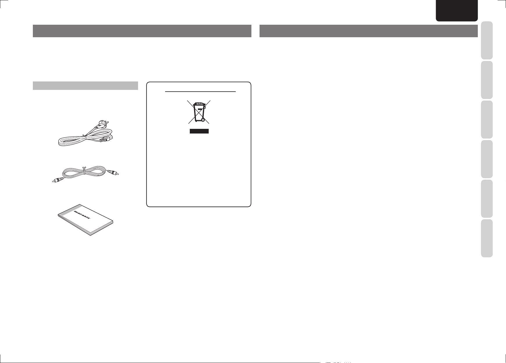
ACCESSORIES CHECK
Before use, check the below accessories were
included in the package.
AC power cable
Remote control cable
User Guide
A NOTE ABOUT RECYCLING
This product’s packaging materials are recyclable
and can be reused. This product and the
accessories packed together are the applicable
product to the WEEE directive except batteries.
Please dispose of any materials in accordance
with your local recycling regulations.
When discarding the unit, comply with your local
rules or regulations.
Batteries should never be thrown away or
incinerated but disposed of in accordance with
your local regulations concerning chemical
wastes.
CONTENTS
INTRODUCTION ....................................1
ACCESSORIES CHECK ....................................................1
CONTENTS ............................................1
FEATURES ............................................. 2
BEFORE USE .........................................2
NAMES AND FUNCTION ......................3
FRONT PANEL ...................................................................3
REAR PANEL .....................................................................3
BASIC CONNECTIONS .........................4
PREPARING THE CONNECTION CABLES ....................4
INPUT CONNECTOR SWITCHING...................................4
AV8003 CONNECTIONS ................................................... 5
SPEAKER CONNECTIONS ...............................................6
POWER CABLE CONNECTION........................................7
OPERATION ........................................... 8
TURNING ON THE POWER ..............................................8
TURNING THE POWER OFF ............................................8
ADVANCED CONNECTIONS ................9
BI-AMPLIFIER CONNECTIONS ........................................ 9
MULTI ZONE SPEAKER CONNECTIONS ......................10
MULTI ZONE CONNECTIONS ........................................ 11
REMOTE CONTROL CONNECTIONS ...........................12
CONNECTIONS WITH EXTERNAL CONTROL
COMPONENTS ................................................................12
TROUBLESHOOTING .........................13
RESETTING THE AMPLIFIER .........................................13
OTHERS ...............................................14
SPECIFICATIONS ............................................................14
FUNCTION
NAMES AND
BASIC
CONNECTIONS
OPERATION
ADVANCED
CONNECTIONS
TROUBLESHOOTING
OTHERS
1
Page 6
ENGLISH
8CH POWER AMPLIFIER MM8003
POWER ON/OFF
STANDBY
FEATURES
This 8-channel power amplifi er comes with upgraded
functions and supports the latest format of surround
sound without compromising the design technology
of Marantz's fl agship models.
Current feedback type of discrete power amplifi er
with high sound quality
The MM8003 features in all 8 channels the current
feedback type of power amplifi er, which uses the
complementary push-pull circuitry incorporated
in Marantz's SM-11S1 Hi-Fi Power Amplifier.
This improves the model's operating stability and
enables it to achieve high-density, high-speed sound
reproduction across a wide sound range.
In the rear section the power amplifi er is a current/
voltage conversion amplifier unit that employs a
Wilson current mirror circuit for amplifying sound up
to the treble range at low distortion levels.
Improved instantaneous current supply
capability
In the rear section of the power amplifier is the
LAPT (high-performance power transistor), which is
featured in Marantz's model SM-11S1 Hi-Fi Power
Amplifi er. This device improves the instantaneous
current supply capability.
Copper bus bars are featured in the unit that supplies
the power to each channel.
The power supply unit has a large toroidal transformer
that delivers low levels of noise and leakage fl ux
thanks to its internal structural features such as its
laminated core, silicon steel-plated core ring,etc.,
and the use of its shielded casing.
Original Marantz parts with a combined capacitance
of 100,000 µF (50,000µF/71V × 2), which have been
specially crafted to achieve the maximum in terms of
sound quality, are employed in the block capacitor, a
key component of the power supply unit.
Thanks to the improvements in the current supply
capability of these parts, you can enjoy high-powered
sound brimming with ambiance.
High-sound-quality design based on the pure
surround concept
A chimney-type heat sink and extremely quiet
cooling fan deal with the heat that is discharged
from the 8-channel amplifi er to a high degree of
effi ciency. A high-precision temperature sensor IC
is used to adjust the rotational speed of the cooling
fan in response to the changes in the amount of heat
generated by the amplifi er.
These features together make for lavish specifi cations
well suited to the amplifi er's use in high-end theater
systems, which are engineered to ensure virtually
noiseless operation.
The amplifi er's chassis is copper-plated to protect
the analog audio circuitry from high-frequency
noise. This is an important technological aspect
for reproducing sound without compromising the
delicately nuanced sound fi elds of Super Audio.
In addition, top-of-the-line audio capacitors, film
capacitors and other high-quality components are
used to achieve a high-sound-quality design.
BALANCED/UNBALANCED switching function
This function makes it possible to select BALANCED
or UNBALANCED input each channel depending on
the application.
Remote power control
By connecting the amplifier to Marantz's model
AV8003 AV pre-tuner, the amplifi er's power can be
switched on or off in tandem with the power on/off
operation of the AV8003 using the remote power
control function.
A fl oating ground connection that doesn’t form a
ground loop is used for the connection with the
AV8003 so the sound quality is not adversely
affected.
Other functions
Also provided are an IR fl asher input connector to
support customized installation, and DC trigger input
connector and output connectors.
BEFORE USE
This section must be read before any connection is
made to the mains supply.
EQUIPMENT MAINS WORKING SETTING
Your Marantz product has been prepared to comply
with the household power and safety requirements
that exist in your area.
MM8003 can be powered by 230V AC only.
COPYRIGHT
Recording and playback of any material may
require consent. For further information refer to the
following:
— Copyright Act 1956
— Dramatic and Musical Performers Act 1958
— Performers Protection Acts 1963 and 1972
— Any subsequent statutory enactments and
orders
DO NOT LOCATE IN THE FOLLOWING PLACES
To ensure long-lasting use, do not locate the unit
where:
• Exposed to direct sunlight.
• Near to sources of heat such as heaters.
• Highly humid or poorly ventilated.
• Dusty.
• Subjected to mechanical vibrations.
• On wobbly, inclined or otherwise unstable
surfaces
• Radiated heat is blocked such as in cramped
audio racks.
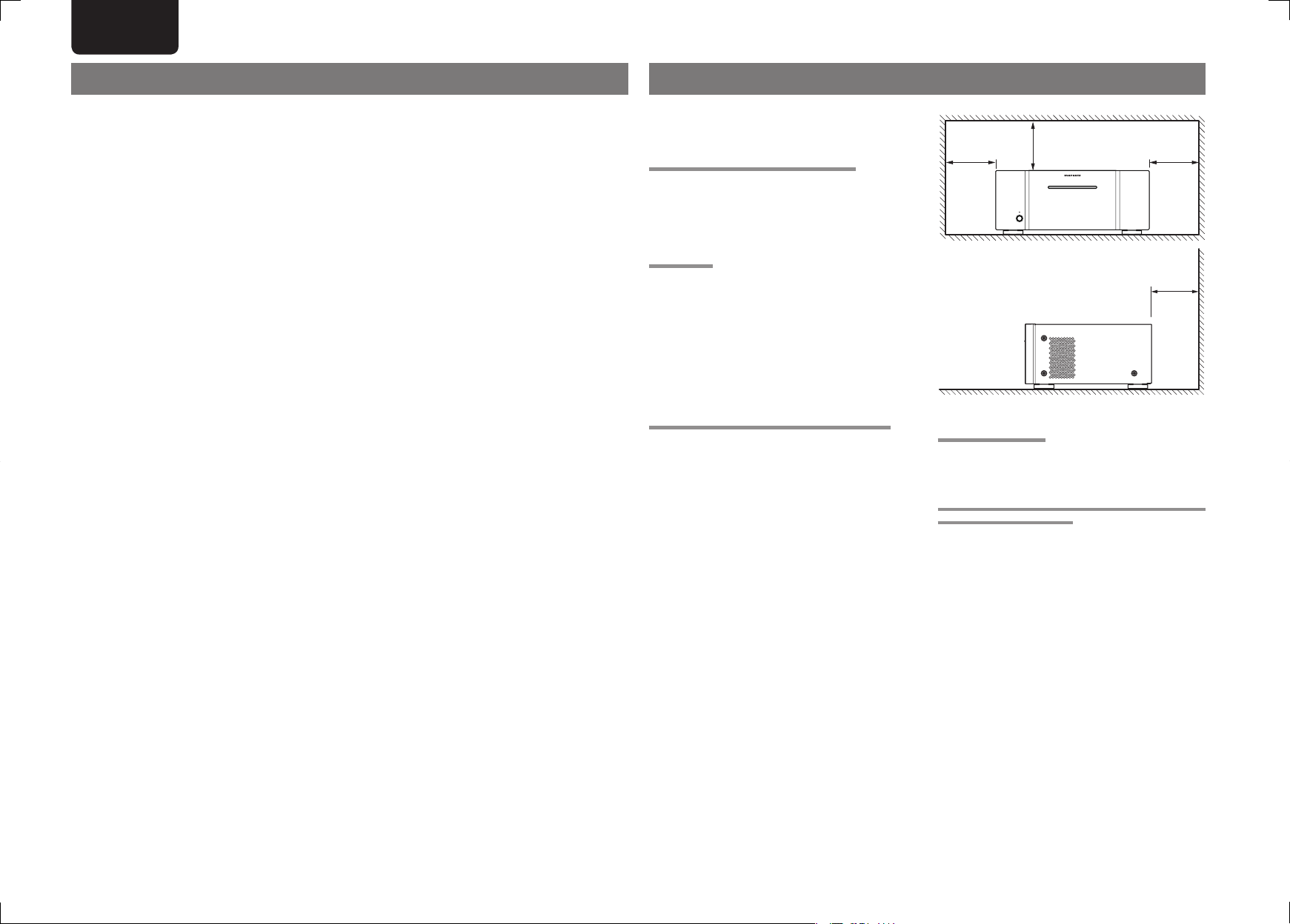
To ensure proper heat radiation, ensure the below
clearance from walls and other equipment.
Left
0.2 m (8 inchs)
or more
Above
0.2 m (8 inchs)
or more
STANDBY
POWER ON/OFF
0.2 m (8 inchs) or
8CH POWER AMPLIFIER MM8003
0.2 m (8 inchs) or
Right
more
Rear
more
KEEP OBJECTS OFF
Keep objects off the unit. Blocking the vent can result
in accident and damage.
DO NOT TOUCH HOT SPOTS DURING AND
IMMEDIATELY AFTER USE
During and immediately after use, the unit is hot
in areas other than the controls and rear panel
connection jacks. Do not touch hot spots and
especially the top panel. Contact with hot areas can
cause burns.
2
Page 7

NAMES AND FUNCTION
8CH POWER AMPLIFI ER MM80 03
POWER ON/ OFF
STANDBY
DC CONTROL
IN
FLASHER
REMOTE CONTROL
SPEAKER SYSTEMS
6-8 OHMS
AC IN
BALANCED
UNBALANCED
BALANCED
UNBALANCED
BALANCED
UNBALANCED
BALANCED
UNBALANCED
BALANCED
UNBALANCED
BALANCED
UNBALANCED
BALANCED
UNBALANCED
BALANCED
UNBALANCED
BALANCED
UNBALANCED
MODEL NO. MM8003
OUT
OUTININ
CHANNEL 1
CHANNEL 2
CHANNEL 3
CHANNEL 4
CHANNEL 5
CHANNEL 6
CHANNEL 7
CHANNEL 8
CHANNEL 1
CHANNEL 2
CHANNEL 3
CHANNEL 4
CHANNEL 5
CHANNEL 6
CHANNEL 7
CHANNEL 8
IN
(
L
)
(
R
)
(
SL
)
(
SR
)
(
SBL
)
(
SBR
)
(
C
)
(
OPTION
)
(
L
)
(
R
)
(
SL
)
(
SR
)
(
SBL
)
(
SBR
)
(
C
)
(
OPTION
)
ENGLISH
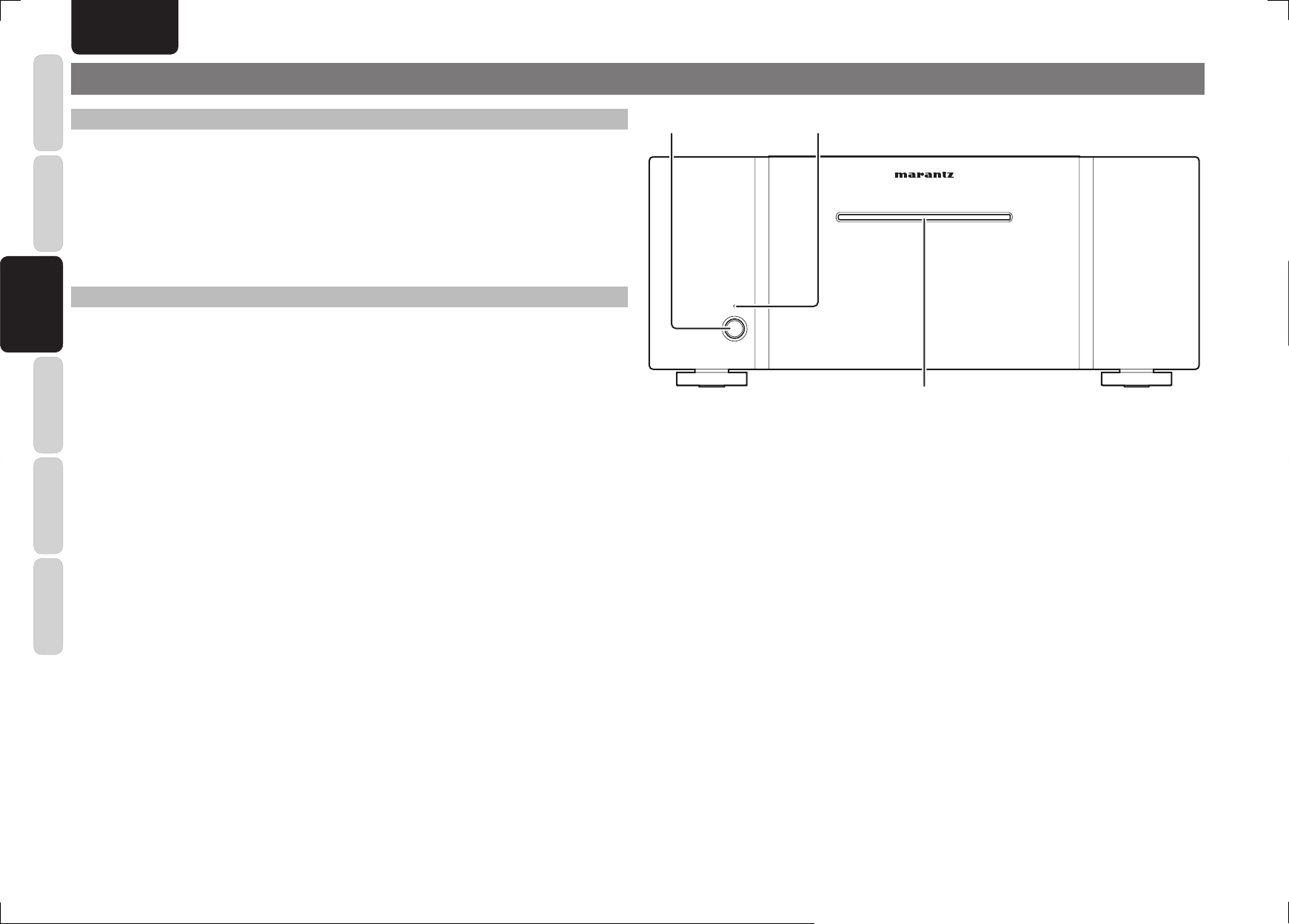
For a more detailed description of the functions of each part, refer to the pages given in ( ).
FRONT PANEL
q w
REAR PANEL
c bnv ,
m
FUNCTION
FUNCTION
NAMES AND
NAMES AND
BASIC
STANDBY
POWER ON/OFF
q POWER ON/OFF button (page 8)
w STANDBY indicator (page 8)
e Illumination lamp (page 8)
8CH POWER AMPLIFIER MM8003
e
CHANNEL 8
(
)
)
C
UNBALANCED
BALANCED
BALANCED
PUSH PUSH PUSH PUSH PUSH PUSH PUSH PUSH
CHANNEL 7
(
)
)
C
z
(
OPTION
UNBALANCED
CHANNEL 8
(
OPTION
x
(
SBR
UNBALANCED
BALANCED
CHANNEL 6
(
SBR
(
)
)
SBL
UNBALANCED
BALANCED
CHANNEL 4
CHANNEL 5
(
)
)
SBL
UNBALANCED
(
SR
BALANCED
(
SR
(
)
)
SL
UNBALANCED
BALANCED
CHANNEL 3
(
)
)
SL
CHANNEL 3
CHANNEL 4
CHANNEL 5
CHANNEL 6
CHANNEL 7
z UNBALANCED (RCA) input connectors (page 5)
x BALANCED (XLR) input connectors (page 5)
CHANNEL 2
(
R
UNBALANCED
BALANCED
CHANNEL 2
(
R
CHANNEL 1
UNBALANCED
(
)
)
L
OUT
OUT
UNBALANCED
BALANCED
BALANCED
2
1
3
(+)
2
1
HOT
GND
)
(
-
3
COLD
CONNECTION
CHANNEL 1
SPEAKER SYSTEMS
6-8 OHMS
(
)
)
L
FLASHER
IN
DC CONTROL
REMOTE CONTROL
IN
AC IN
MODEL NO. MM8003
CONNECTIONS
OPERATION
ADVANCED
CONNECTIONS
TROUBLESHOOTING
c Input selector switches (page 4)
v SPEAKER SYSTEMS output connectors (page 6)
b Flasher input connector (page 12)
OTHERS
n DC CONTROL IN/OUT connectors (page 12)
m REMOTE CONTROL IN, OUT connectors (page 12)
, AC IN socket (page 7)
3
Page 8

ENGLISH
BALANCED
UNBALANCED
BBALANCED
UUNBALANCED
BALANCED
UNBALANCED
BALANCED
UNBALANCED
BALANCED
UNBALANCED
BALANCED
UNBALANCED
BALANCED
UNBALANCED
BALANCED
UNBALANCED
BALANCED
UNBALANCED
CHANNEL 1
CHANNEL 2
CHANNEL 3
CHANNEL 4
CHANNEL 5
CHANNEL 6
CHANNEL 7
CHANNEL 8
(
L
)
(
R
)
(
SL
)
(
SR
)
(
SBL
)
(
SBR
)
(
C
)
(
OPTION
)
NAMES AND
FUNCTION
BASIC CONNECTIONS
PREPARING THE CONNECTION CABLES
Provide the cables required by the component to
be used.
CONNECTIONS
CONNECTIONS
BASIC
BASIC
BALANCED CONNECTIONS
XLR audio cable
Male Female
PUSH
3
1
12
OPERATION
q This amplifi er uses XLR connectors, which are
widely used in professional audio applications, for
the BALANCED connectors. Their features are
described below.
• Due to their 3-pin construction, the music signals
can be transmitted as balanced signals, and the
CONNECTIONS
effects of extraneous noise are minimal.
ADVANCED
• Their connect/disconnect locking mechanism
minimizes any shakiness in the connector area
and performs high reliability.
w For professional audio applications, the XLR
connectors can be connected in the following two
TROUBLESHOOTING
ways.
1. European system (pin w = hot, pin e = cold)
HOT
2 1
GND
3
COLD
OTHERS
2. U.S. system (pin w = cold, pin e = hot)
UNBALANCED CONNECTIONS
RCA audio cable
REMOTE CONTROL CONNECTIONS
RCA cable (accessory)
(This cable is required to connect the AV8003 or
3
12
other Marantz component to this amplifi er.)
SPEAKER CONNECTIONS
Speaker cable
INPUT CONNECTOR SWITCHING
A BALANCED or UNBALANCED input for the input connectors can be selected for each channel.
Input selector switches
CHANNEL 8
(
)
OPTION
UNBALANCED
BALANCED
PUSH PUSH PUSH PUSH PUSH PUSH PUSH PUSH
CHANNEL 7
(
)
C
UNBALANCED
BALANCED
CHANNEL 6
(
)
SBR
UNBALANCED
BALANCED
CHANNEL 5
(
)
SBL
UNBALANCED
BALANCED
CHANNEL 4
(
SR
UNBALANCED
BALANCED
CHANNEL 3
)
(
SL
UNBALANCED
BALANCED
CHANNEL 2
(
)
R
UNBALANCED
BALANCED
)
BALANCED:
The XLR audio cable is used for connection with the control amplifi er.
UNBALANCED:
The RCA audio cable is used for connection with the control amplifi er.
Notes:
• Select the input, whether balanced or unbalanced, before turning on the power. Failure may occur if it is
selected after the power has already been turned on.
• If the amplifi er input and input selector switch settings are incorrectly matched, no sound will be output from
the amplifi er.
CHANNEL 1
(
)
L
UNBALANCED
BALANCED
GND
3
COLD
2 1
HOT
e The XLR connectors on this amplifier use the
European system in 1. above. If a pre-amplifi er
or control amplifi er with connectors using the U.S.
system is connected to this amplifi er using balanced
cables, the signal phase will be reversed.
To correct the signal phase, reverse the connections
of pins w and e of the XLR connector at one end
of the cable.
4
Page 9

ENGLISH
DC CONTROL
IN
FLASHER
REMOTE CONTROL
SPEAKER SYSTEMS
6-8 OHMS
AC IN
BALANCED
UNBALANCED
BALANCED
UNBALANCED
BALANCED
UNBALANCED
BALANCED
UNBALANCED
BALANCED
UNBALANCED
BALANCED
UNBALANCED
BALANCED
UNBALANCED
BALANCED
UNBALANCED
BALANCED
UNBALANCED
MODEL NO. MM8003
OUT
OUTININ
CHANNEL 1
CHANNEL 2
CHANNEL 3
CHANNEL 4
CHANNEL 5
CHANNEL 6
CHANNEL 7
CHANNEL 8
CHANNEL 1
CHANNEL 2
CHANNEL 3
CHANNEL 4
CHANNEL 5
CHANNEL 6
CHANNEL 7
CHANNEL 8
IN
(
L
)
(
R
)
(
SL
)
(
SR
)
(
SBL
)
(
SBR
)
(
C
)
(
OPTION
)
(
L
)
(
R
)
(
SL
)
(
SR
)
(
SBL
)
(
SBR
)
(
C
)
(
OPTION
)
BALANCED
UNBALANCED
BALANCED
UNBALANCED
BALANCED
UNBALANCED
BALANCED
UNBALANCED
BALANCED
UNBALANCED
BALANCED
UNBALANCED
CHANNEL 2
CHANNEL 3
CHANNEL 4
CHANNEL 5
CHANNEL 6
CHANNEL 7
(
R
)
(
SL
)
(
SR
)
(
SBL
)
(
SBR
)
(
C
)
CHANNEL 1
(
L
)
BALANCED
UNBALANCED
SL
R
R
SL
C
SBR
SBL
L
SBLSWSWCC
SBR
FM
(
Ω
)
GNDAMAM
ANTENNA
OUT
PUT
1
OUT
PUT
2
INPUT 3
(
VCR1
)
OUTPUT 1
OUTPUT 2
INPUT 1
(
TV
)
INPUT 4
(
DSS/VCR2
)
INPUT 2
(
DVD
)
COMPONENT
VIDEO
C
B
/
P
B
C
R
/
P
R
C
R
/
P
R
C
R
/
P
R
C
B
/
P
B
C
B
/
P
B
Y
Y
Y
INPUT 1
(
TV
)
INPUT 4
(
DSS //
VCR2
)
INPUT 3
(
VCR1
)
INPUT 2
(
DVD
)
RS-232C
NETWORK
AC IN
OUT
OUT
OUT
OUT
MONITOR
OUT
DVD
(
2
)
DSS/VCR2
(
4
)
TV
(
1
)
ZONE
OUT
VCR1
(
3
)
DVD
(
2
)
DSS/VCR2
(
4
)
VCR1
(
3
)
TV
(
1
)
MONI. OUT
2
1
FLASHER
IN
IR
RECEIVER
IN
COAX.
4
OUT
IN
1
2
EMITTER
OUT
DC OUT
DIGITAL IN
DIGITAL OUT
MAIN
ZONE
L
REMOTE
CD/CDR BALANCED IN
OUT
R
OUT
L
TAPE
CD/CDR
OUTININININ
R
OUT
L
DSS/VCR2
AUDIO
BALANCED
UNBALANCED
TV
IN
SR
VCR1
IN
DVD
SL
SBR
SBL
SW
C
B
7.1CH
IN
(
AUX
)
1
OPT.
SPEAKER C
OFF
PRE OUT
BALANCED
UNBALANCED
VIDEO
S-VIDEO
ZONE OUT
MODEL NO. AV8003
SELECTOR
L
SR
SL
R
C
L
SBL
SW
C
SBR
NETWORK
BALANCEDE
SPEAKER C
PRE OUT
BALANCEDBALANCED
UNBALANCEDUNBALANCED
DC CONTROL
IN
FLASHER
REMOTE CONTROL
SPEAKER SYSTEMS
6-8 OHMS
AC IN
BALANCED
UNBALANCED
BALANCED
UNBALANCED
BALANCED
UNBALANCED
BALANCED
UNBALANCED
BALANCED
UNBALANCED
BALANCED
UNBALANCED
BALANCED
UNBALANCED
BALANCED
UNBALANCED
BALANCED
UNBALANCED
MODEL NO. MM8003
OUT
OUTININ
CHANNEL 1
CHANNEL 2
CHANNEL 3
CHANNEL 4
CHANNEL 5
CHANNEL 6
CHANNEL 7
CHANNEL 8
CHANNEL 1
CHANNEL 2
CHANNEL 3
CHANNEL 4
CHANNEL 5
CHANNEL 6
CHANNEL 7
CHANNEL 8
IN
(
L
)
(
R
)
(
SL
)
(
SR
)
(
SBL
)
(
SBR
)
(
C
)
(
OPTION
)
(
L
)
(
R
)
(
SL
)
(
SR
)
(
SBL
)
(
SBR
)
(
C
)
(
OPTION
)
BALANCED
UNBALANCED
BALANCED
UNBALANCED
BALANCED
UNBALANCED
BALANCED
UNBALANCED
BALANCED
UNBALANCED
BALANCED
UNBALANCED
BALANCED
UNBALANCED
CHANNEL 1
CHANNEL 2
CHANNEL 3
CHANNEL 4
CHANNEL 5
CHANNEL 6
CHANNEL 7
(
L
)
(
R
)
(
SL
)
(
SR
)
(
SBL
)
(
SBR
)
(
C
)
SL
R
R
SL
C
SBR
SBL
L
SBLSWSWCC
SBR
FM
(
Ω
)
GNDAMAM
ANTENNA
OUT
PUT
1
OUT
PUT
2
INPUT 3
(
VCR1
)
OUTPUT 1
OUTPUT 2
INPUT 1
(
TV
)
INPUT 4
(
DSS/VCR2
)
INPUT 2
(
DVD
)
COMPONENT
VIDEO
C
B
/
P
B
C
R
/
P
R
C
R
/
P
R
C
R
/
P
R
C
B
/
P
B
C
B
/
P
B
Y
Y
Y
INPUT 1
(
TV
)
INPUT 4
(
DSS //
VCR2
)
INPUT 3
(
VCR1
)
INPUT 2
(
DVD
)
RS-232C
NETWORK
AC IN
OUT
OUT
OUT
OUT
MONITOR
OUT
DVD
(
2
)
DSS/VCR2
(
4
)
TV
(
1
)
ZONE
OUT
VCR1
(
3
)
DVD
(
2
)
DSS/VCR2
(
4
)
VCR1
(
3
)
TV
(
1
)
MONI. OUT
2
1
FLASHER
IN
IR
RECEIVER
IN
COAX.
4
OUT
IN
1
2
EMITTER
OUT
DC OUT
DIGITAL IN
DIGITAL OUT
MAIN
ZONE
L
REMOTE
CD/CDR BALANCED IN
OUT
R
OUT
L
TAPE
CD/CDR
OUTININININ
R
OUT
L
DSS/VCR2
AUDIO
BALANCED
UNBALANCED
TV
IN
SR
VCR1
IN
DVD
SL
SBR
SBL
SW
C
B
7.1CH
IN
(
AUX
)
1
OPT.
SPEAKER C
OFF
PRE OUT
BALANCED
UNBALANCED
VIDEO
S-VIDEO
ZONE OUT
MODEL NO. AV8003
SELECTOR
LL SRSR SLSLRR
RR
SRSR SLSL
SWSW CC
SBRSBR SBLSBL
LL
SBLSBL SWSW CCSBRSBR
RS-232CRS-232C
NETWORKNETWORK
1
3
CONNECTION
GND
HOT
(+)
COLD
(
-
)
3
2
1
2
BALANCEDBALANCEDUNBALANCEDUNBALANCED
SPEAKER CSPEAKER C
PRE OUTPRE OUT
3
12312312
3
12
3
12
3
12
BALANCEDBALANCED
UNBALANCEDUNBALANCED
AV8003 CONNECTIONS
The connection example given below shows the connections between the amplifi er and AV8003 AV pre-tuner for basic sound reproduction through 7 channels.
When using the BALANCED inputs, use the XLR audio cables; when using the UNBALANCED inputs, use the RCA audio cables. Connect the PRE OUT connectors on the control amplifi er to the input connectors on this
amplifi er. Use this connection example as a reference when a control amplifi er other than the AV8003 is to be used.
Notes:
• Do not connect the power cables of this amplifi er and other components to the AC outlet until all the connections have been completed.
• Insert the plugs on the connecting cables fi rmly into the connectors. Noise may be caused by improper connections.
• For details on the components connected to this amplifi er, refer to the operating instructions of each component.
BALANCED CONNECTIONS
L
L
L
R
L
C
SBL
SBR
D
2C
PRE OUT
BALANCED
SPEAKER C
SR
SW
XLR audio cables
AV PRE TUNER AV8003
(
FM
7575Ω
INPUT 1
(
)
TV
1
VIDEO
554
DIGITAL IN
TV
L
R
SL
CONNECTION
1
GND
2
HOT
3
COLD
NETWORK
C
)
ANTENNA
(
DVD
2
DVD
(+)
GND
(
)
TV
INPUT 2
)
VCR1
ININININOUT
66COAX.
33221
VCR1
IN
(
)
-
(
)
3
DIGITAL OUT
OUT
1
(
DVD
3
COMPONENT
VIDEO
)
INPUT 3
(
DSS/VCR2
OUT
OPT.
MAIN
DSS/VCR2
OUT
IN
2
(
)
(
)
INPUT 1
TV
INPUT 2
DVD
C
B
C
R
C
R
C
R
C
B
C
B
Y
/
P
B
(
INPUT 3
VCR1
(
)
(
VCR1
INPUT 4
DSS/VCR2
)
MONITOR
4
ZONE
TV
OUT
OUT
DC OUT
REMOTE
1
IN
2
OUT
ZONE
TAPE
OUT
AUDIO
S-VIDEO
/
P
)
(
CD/CDR
R
)
)
1
Y
INPUT 4
OUTPUT 1
(
)
DVD
2
FLASHER
IN
OUT
RECEIVER
(
ININOUT
ZONE OUT
Y
/
/
/
/
P
R
P
R
P
B
P
B
)
DSS
VCR2
OUTPUT 2
(
)
(
)
DSS/VCR2
4
VCR1
3
MONI. OUT
ININOUT
CD/CDR BALANCED IN
PUSH PUSH
1
IR
IN
12
2
EMITTER
RRL
OUT
L
SL
SBL
AAB
R
SR
SBR
(
)
AUX
L
R
OUT
PUT
1
SRSRSL
OUT
PUT
2
SBR
SBL
SWSWC
UNBALANCED
RS-232C
CONNECTION
1
GND
(+)
2
HOT
2
1
3
)
(
-
3
COLD
3123
AC IN
UNBALANCED
BALANCED
SELECTOR
C
7.1CH
IN
SW
3
3123
12
12312
LLSRSRSL
R
3123123123
SBL
SBR
BALANCED
PRE OUT
SPEAKER C
ONONOFF
MODEL NO. AV8003
Subwoofer inside
the amplifi er
Set the switch to
BALANCED.
12
CONNECTION
1
2
3
GND
(+)
HOT
(
)
-
COLD
NETWORK
UNBALANCED CONNECTIONS
2
1
3
AV PRE TUNER AV8003
(
)
FM
7575Ω
GND
ANTENNA
(
)
INPUT 1
TV
INPUT 2
(
)
(
)
(
DVD
2
TV
1
VCR1
3
VIDEO
ININININOUT
66COAX.
554
33221
DIGITAL IN
TV
VCR1
DVD
L
R
OUT
IN
(
)
INPUT 1
TV
C
B
C
R
Y
/
/
COMPONENT
P
B
P
VIDEO
(
)
INPUT 3
VCR1
(
)
(
(
)
INPUT 3
VCR1
INPUT 4
DSS/VCR2
DVD
(
)
)
MONITOR
DSS/VCR2
4
ZONE
(
TV
1
OUT
OUT
S-VIDEO
OUT
DC OUT
REMOTE
1
IN
OPT.
2
OUT
DIGITAL OUT
MAIN
ZONE
TAPE
CD/CDR
DSS/VCR2
OUT
OUT
IN
AUDIO
RCA audio cables
(
)
INPUT 2
DVD
C
R
C
R
C
B
C
B
Y
Y
/
/
/
/
R
P
R
P
R
P
B
P
B
(
)
INPUT 4
DSS
VCR2
)
OUTPUT 1
OUTPUT 2
(
)
(
)
DSS/VCR2
4
VCR1
3
(
)
DVD
2
)
FLASHER
IN
OUT
MONI. OUT
ININOUT
ININOUT
CD/CDR BALANCED IN
PUSH PUSH
1
IR
RECEIVER
IN
12
2
EMITTER
RRL
OUT
L
SL
SBL
ZONE OUT
AAB
R
SR
SBR
(
)
AUX
L
R
OUT
PUT
1
SRSRSL
OUT
PUT
2
2
3
3123
SELECTOR
C
SW
Subwoofer inside
SBR
SBL
SWSWC
UNBALANCED
RS-232C
CONNECTION
1
GND
(+)
2
HOT
1
(
)
-
3
COLD
AC IN
UNBALANCED
BALANCED
7.1CH
IN
the amplifi er
R
SBR
PRE OUT
Set the switch to
UNBALANCED.
LLSRSRSL
SBL
BALANCED
SPEAKER C
ONONOFF
MODEL NO. AV8003
CONNECTION
1
2
3
GND
(+)
HOT
2
1
3
(
)
-
COLD
NETWORK
FUNCTION
NAMES AND
BASIC
BASIC
CONNECTIONS
CONNECTIONS
OPERATION
ADVANCED
CONNECTIONS
CHANNEL 8
(
)
OPTION
UNBALANCED
BALANCED
PUSH PUSH PUSH PUSH PUSH PUSH PUSH PUSH
CHANNEL 8
(
)
OPTION
CHANNEL 6
CHANNEL 7
(
)
(
)
(
)
(
)
SBR
C
SBR
C
UNBALANCED
UNBALANCED
UNBALANCED
UNBALANCED
BALANCED
BALANCED
BALANCED
BALANCED
PUSH PUSH PUSH PUSH PUSH PUSH
CHANNEL 6
CHANNEL 7
(
(
)
)
SBR
C
CHANNEL 5
(
(
SBL
SBL
UNBALANCED
UNBALANCED
BALANCED
BALANCED
CHANNEL 5
(
SBL
)
)
)
CHANNEL 4
CHANNEL 4
(
(
SR
SR
UNBALANCED
UNBALANCED
BALANCED
BALANCED
(
SR
)
)
)
CHANNEL 4
CHANNEL 5
CHANNEL 6
CHANNEL 7
CHANNEL 3
CHANNEL 3
UNBALANCED
UNBALANCED
CHANNEL 3
(
)
(
)
SL
SL
BALANCED
BALANCED
(
)
SL
CHANNEL 2
CHANNEL 2
CHANNEL 2
(
(
R
R
UNBALANCED
UNBALANCED
BALANCED
BALANCED
(
R
TROUBLESHOOTING
UNBALANCED
CHANNEL 1
CHANNEL 1
(
)
)
)
(
)
L
L
OUT
OUT
UNBALANCED
UNBALANCED
BALANCED
BALANCED
PUSH
BALANCED
2
1
GND HOT
3
COLD
CONNECTION
1
3
(+)
2
)
(
-
FLASHER
IN
DC CONTROL
REMOTE CONTROL
IN
CHANNEL 8
(
)
OPTION
UNBALANCED
BALANCED
PUSH PUSH PUSH PUSH PUSH PUSH PUSH PUSH
CHANNEL 7
CHANNEL 7
(
)
(
)
C
C
UNBALANCED
UNBALANCED
BALANCED
BALANCED
CHANNEL 6
CHANNEL 6
(
(
SBR
SBR
UNBALANCED
UNBALANCED
BALANCED
BALANCED
)
)
CHANNEL 5
CHANNEL 5
(
(
SBL
SBL
UNBALANCED
UNBALANCED
BALANCED
BALANCED
CHANNEL 4
CHANNEL 4
(
)
)
(
)
)
SR
SR
UNBALANCED
UNBALANCED
BALANCED
BALANCED
CHANNEL 3
CHANNEL 3
(
(
SL
SL
UNBALANCED
UNBALANCED
BALANCED
BALANCED
CHANNEL 2
CHANNEL 2
(
)
)
(
)
)
R
R
UNBALANCED
UNBALANCED
BALANCED
BALANCED
AC IN
CHANNEL 1
SPEAKER SYSTEMS
6-8 OHMS
(
)
)
L
MODEL NO. MM8003
CHANNEL 8
(
OPTION
)
CHANNEL 7
(
C
CHANNEL 6
(
)
)
SBR
CHANNEL 5
(
SBL
CHANNEL 4
(
)
)
SR
CHANNEL 3
(
SL
CHANNEL 2
(
)
)
R
CHANNEL 1
CHANNEL 1
(
(
L
L
UNBALANCED
UNBALANCED
BALANCED
BALANCED
CHANNEL 1
(
L
UNBALANCED
)
)
OUT
OUT
IN
FLASHER
DC CONTROL
REMOTE CONTROL
BALANCED
2
1
GND HOT
3
COLD
CONNECTION
IN
1
3
(+)
2
(
)
-
OTHERS
AC IN
SPEAKER SYSTEMS
6-8 OHMS
)
MODEL NO. MM8003
5
Page 10

ENGLISH
DC CONTROL
IN
FLASHER
REMOTE CONTROL
SPEAKER SYSTEMS
6-8 OHMS
AC IN
BALANCED
UNBALANCED
BALANCED
UNBALANCED
BALANCED
UNBALANCED
BALANCED
UNBALANCED
BALANCED
UNBALANCED
BALANCED
UNBALANCED
BALANCED
UNBALANCED
BALANCED
UNBALANCED
BALANCED
UNBALANCED
MODEL NO. MM8003
OUT
OUTININ
CHANNEL 1
CHANNEL 2
CHANNEL 3
CHANNEL 4
CHANNEL 5
CHANNEL 6
CHANNEL 7
CHANNEL 8
CHANNEL 1
CHANNEL 2
CHANNEL 3
CHANNEL 4
CHANNEL 5
CHANNEL 6
CHANNEL 7
CHANNEL 8
IN
(
L
)
(
R
)
(
SL
)
(
SR
)
(
SBL
)
(
SBR
)
(
C
)
(
OPTION
)
(
L
)
(
R
)
(
SL
)
(
SR
)
(
SBL
)
(
SBR
)
(
C
)
(
OPTION
)
CHANNEL 1
CHANNEL 2
CHANNEL 3
CHANNEL 4
CHANNEL 5
CHANNEL 6
CHANNEL 7
(
L
)
(
R
)
(
SL
)
(
SR
)
(
SBL
)
(
SBR
)
(
C
)
NAMES AND
FUNCTION
SPEAKER CONNECTIONS
SPEAKER CONNECTIONS
Refer to the fi gure below, and connect the speakers to the amplifi er.
CONNECTIONS
CONNECTIONS
CHANNEL 3
CHANNEL 4
CHANNEL 5
CHANNEL 6
CHANNEL 7
BASIC
BASIC
OPERATION
CONNECTIONS
ADVANCED
TROUBLESHOOTING
CHANNEL 8
(
(
OPTION
UNBALANCED
CHANNEL 8
(
OPTION
)
)
C
UNBALANCED
BALANCED
BALANCED
PUSH PUSH PUSH PUSH PUSH PUSH PUSH PUSH
CHANNEL 7
CHANNEL 7
(
)
)
(
)
C
C
(
SBR
UNBALANCED
BALANCED
CHANNEL 6
CHANNEL 6
(
(
SBR
SBR
(
)
)
SBL
UNBALANCED
BALANCED
CHANNEL 4
CHANNEL 5
CHANNEL 4
CHANNEL 5
(
)
)
(
)
)
SBL
SBL
(
UNBALANCED
BALANCED
(
(
(
)
)
SL
SR
UNBALANCED
BALANCED
CHANNEL 3
CHANNEL 3
(
)
)
(
)
)
SL
SR
SL
SR
CHANNEL 2
(
UNBALANCED
BALANCED
CHANNEL 2
CHANNEL 2
(
(
SPEAKER CABLES
1. Remove about 10 mm of the covering from the
end of the speaker cable.
Twist the bare part of the cable tightly to prevent
2.
CHANNEL 1
UNBALANCED
(
)
)
L
R
OUT
OUT
UNBALANCED
BALANCED
BALANCED
2
1
3
(+)
2
1
HOT
GND
(
)
-
3
COLD
CONNECTION
CHANNEL 1
CHANNEL 1
SPEAKER SYSTEMS
6-8 OHMS
(
)
)
(
)
)
L
R
L
R
FLASHER
IN
DC CONTROL
REMOTE CONTROL
IN
AC IN
MODEL NO. MM8003
short-circuiting.
Turn the speaker connector counterclockwise
3.
to loosen it.
Insert the bare part of the speaker cable into
4.
the hole at the side of the speaker connector.
Turn the speaker connector clockwise to
5.
tighten it up.
1. 2.
Notes:
• To protect the circuitry from damage, do not connect
two bare speaker cables together or allow them to
touch any metal parts of the amplifi er.
• Due to the risk of electric shock, do not touch the
speaker connectors while the power is supplied.
3. 4. 5.
OTHERS
Center speaker
(C)
Surround
speaker
back
right
(SBR)
Surround
back left
speaker
(SBL)
Surround
right
speaker
(SR)
Surround
left
speaker
(SL)
Front
right
speaker
(R)
Front
left
speaker
(L)
Notes:
• Speakers come with "+" and "-" terminals. When connecting the speakers to the amplifi er, connect their "+"
terminals to the "+" connectors on the amplifi er and, similarly, connect their "-" terminals to the "-" connectors.
If a "+" terminal is connected to a "-" connector, the signal phase will be reversed, and the music played through
the speakers will sound unnatural. Refer to the operating instructions of the speakers, and properly reconnect the
speakers.
• Connect speaker systems with an impedance of at least 6 Ω to the amplifi er. If speakers with an impedance of under
6 Ω are used and sound is played at high volume levels for prolonged periods, the amplifi er may experience an
extreme rise in temperature, tripping the protection circuit.
• If the AV8003 AV pre-tuner is connected to the amplifi er and one surround back speaker is to be used, connect the
speaker to the surround back left channel (SBL).
If this is the case, the setting must be performed on the AV8003. (For details, refer to the operating instructions of the
AV8003.) When using a control amplifi er other than the AV8003, follow the operating instructions of the amplifi er
used, and connect the speaker properly.
6
Page 11

ENGLISH
TIPS ON SPEAKER PLACEMENT
How the speakers should be placed depends on the room size and other factors. An example of how the
speakers are normally placed and some placement tips are given here.
Surround R
Front R
Front
Center
Front L
• Front left and right speakers
It is recommended that the front left and right
speakers be positioned at an angle of 45 to 60
degrees from each other as viewed from the listening
position.
• Center speaker
This speaker is placed so that its front panel is in
line with the front panels of the front left and right
speakers or slightly behind them.
Height at which to place the front left and right
speakers and center speaker
Place the three front speakers (left, right and center)
so that their mid-range and high-range units will be
positioned at more or less the same height from the
fl oor as much as possible.
Surround L
Surround
Back R
Surround
Back L
• Surround left and right speakers
These speakers are needed to play surround sound.
Place them against the walls in line with the listening
position or slightly behind it. Position them so that
the center of the speaker front panels point toward
the center the room.
• Surround back left and right speakers
Place these speakers behind the listening position as
shown in the fi gure.
Height at which to place the surround left and
right speakers and surround back left and right
speakers
Place these speakers at a height of 70 cm to 1 meter
above the listener.
By placing the speakers at this height, the sound
source will not be localized at any specifi c position,
and the listener will feel more surrounded and
enveloped by the sound.
POWER CABLE CONNECTION
Connect the power cable after all the connections
have been completed.
Plug the accessory power cable into the AC IN
1.
socket on the rear panel of the amplifi er.
2. Connect the plug on the power cable to the wall
socket (AC 230 V, 50 Hz).
* Ensure that the total power consumption of the
amplifi er and other components connected to
the socket does not exceed the capacity of
the socket.
Notes:
• Insert the power plug fi rmly. Noise may be caused
by an incomplete connection.
• Do not connect the amplifi er to the AC outlet of
another product. Product malfunctioning may occur
if the capacity of the AC outlet is exceeded.
FUNCTION
NAMES AND
BASIC
BASIC
CONNECTIONS
CONNECTIONS
OPERATION
ADVANCED
CONNECTIONS
TROUBLESHOOTING
OTHERS
Note:
When placing speakers close to a TV set, use
magnetically shielded speakers for the front left and
right speakers and center speaker.
70cm 1m
7
Page 12
ENGLISH
8CH POWER AMPLIFI ER MM80 03
POWER ON/ OFF
STANDBY
NAMES AND
FUNCTION
OPERATION
TURNING THE POWER ON
1. Press the POWER ON/OFF switch.
CONNECTIONS
Sound is output after the illumination lamp has blinked for about 7 seconds.
2.
The sound output is delayed because of the activation of the muting circuit, which prevents noise from being output
BASIC
until the amplifi er's circuitry operates stably after the power has been turned on.
(The illumination lamp is lit while the amplifi er is operating.)
Note:
Before turning the power on, turn down the volume controls on the connected components.
OPERATION
OPERATION
TURNING THE POWER OFF
1. Press the POWER ON/OFF switch.
The illumination lamp goes off and turns the power off.
2.
CONNECTIONS
Note:
ADVANCED
• The Standby indicator does not light even when the unit is off.
• By connecting the remote control connectors on the AV8003 and this amplifi er, the amplifi er can be set to
STANDBY ON/OFF synchronized with the STANDBY ON/OFF operations of the AV8003.
For details, refer to REMOTE CONTROL CONNECTIONS (page 12) and the AV8003 user guide.
TROUBLESHOOTING
POWER ON/OFF switch
STANDBY
POWER ON/OFF
Standby indicator
8CH POWER AMPLIFIER MM8003
Illumination lamp
OTHERS
8
Page 13

ADVANCED CONNECTIONS
DC CONTROL
IN
FLASHER
REMOTE CONTROL
SPEAKER SYSTEMS
6-8 OHMS
AC IN
BALANCED
UNBALANCED
BALANCED
UNBALANCED
BALANCED
UNBALANCED
BALANCED
UNBALANCED
BALANCED
UNBALANCED
BALANCED
UNBALANCED
BALANCED
UNBALANCED
BALANCED
UNBALANCED
BALANCED
UNBALANCED
MODEL NO. MM8003
OUT
OUTININ
CHANNEL 1
CHANNEL 2
CHANNEL 3
CHANNEL 4
CHANNEL 5
CHANNEL 6
CHANNEL 7
CHANNEL 8
CHANNEL 1
CHANNEL 2
CHANNEL 3
CHANNEL 4
CHANNEL 5
CHANNEL 6
CHANNEL 7
CHANNEL 8
IN
(
L
)
(
R
)
(
SL
)
(
SR
)
(
SBL
)
(
SBR
)
(
C
)
(
OPTION
)
(
L
)
(
R
)
(
SL
)
(
SR
)
(
SBL
)
(
SBR
)
(
C
)
(
OPTION
)
CHANNEL 1
CHANNEL 2
CHANNEL 3
CHANNEL 4
CHANNEL 5
CHANNEL 6
CHANNEL 7
(
L
)
(
R
)
(
SL
)
(
SR
)
(
SBL
)
(
SBR
)
(
C
)
SPEAKER SYSTEMS
6-8 OHMS
CHANNEL 1
CHANNEL 2
CHANNEL 3
CHANNEL 4
CHANNEL 5
CHANNEL 6
CHANNEL 7
(
L
)
(
R
)
(
SL
)
(
SR
)
(
SBL
)
(
SBR
)
(
C
)
SL
R
R
SL
C
SBR
SBL
L
SBLSWSWCC
SBR
FM
(
Ω
)
GNDAMAM
ANTENNA
OUT
PUT
1
OUT
PUT
2
INPUT 3
(
VCR1
)
OUTPUT 1
OUTPUT 2
INPUT 1
(
TV
)
INPUT 4
(
DSS/VCR2
)
INPUT 2
(
DVD
)
COMPONENT
VIDEO
C
B
/
P
B
C
R
/
P
R
C
R
/
P
R
C
R
/
P
R
C
B
/
P
B
C
B
/
P
B
Y
Y
Y
INPUT 1
(
TV
)
INPUT 4
(
DSS //
VCR2
)
INPUT 3
(
VCR1
)
INPUT 2
(
DVD
)
RS-232C
NETWORK
AC IN
OUT
OUT
OUT
OUT
MONITOR
OUT
DVD
(
2
)
DSS/VCR2
(
4
)
TV
(
1
)
ZONE
OUT
VCR1
(
3
)
DVD
(
2
)
DSS/VCR2
(
4
)
VCR1
(
3
)
TV
(
1
)
MONI. OUT
2
1
FLASHER
IN
IR
RECEIVER
IN
6
COAX.
4
OUT
IN
1
2
EMITTER
OUT
DC OUT
DIGITAL IN
DIGITAL OUT
MAIN
ZONE
L
REMOTE
CD/CDR BALANCED IN
OUT
R
OUT
L
TAPE
CD/CDR
OUTININININ
R
OUT
L
DSS/VCR2
AUDIO
BALANCED
UNBALANCED
TV
IN
SR
VCR1
IN
DVD
SL
SBR
SBL
SW
C
B
7.1CH
IN
(
AUX
)
1
OPT.
SPEAKER C
OFF
PRE OUT
BALANCED
UNBALANCED
VIDEO
S-VIDEO
ZONE OUT
MODEL NO. AV8003
SELECTOR
ONON OFFOFF
LL SRSR SLSLRR
SLSL
CC
SBLSBL
LL
SBLSBL SWSW CCSBRSBR
RS-232CRS-232C
NNETWORK
CONN
GN
HO
CO
3
2
1
BALANCEDBALANCEDANCEDUNBALANCED
SPEAKER CSPEAKER C
ONON OFFOFF
PRE OUTPRE OUT
ENGLISH
BI-AMPLIFIER CONNECTIONS
Four channels of this unit's power amplifi ers are used to achieve bi-amplifi er connections to the front speaker
systems.
Before connecting the speaker systems, check that they support bi-amplifi er connections.
What are "bi-amplifi er connections"?
This is a technique for enhancing sound quality, and it involves connecting separate power amplifi ers to the
bass and mid-range/treble speakers.
By adopting this technique, interference in the mid-range and treble sound caused by the back electromotive
force generated by the bass speaker unit can be minimized, improving the sound that can be delivered through
Notes:
• Balanced cables are used in the connection example shown. (Unbalanced cables can also be used for bi-amplifi er
connections.)
• If the front speaker systems are used in combination with the AV8003 in a bi-amplifi er connection, sound will no
longer be heard from the surround back channels.
FUNCTION
NAMES AND
BASIC
CONNECTIONS
the front speakers.
OPERATION
CHANNEL 8
CHANNEL 7
(
(
OPTION
UNBALANCED
CHANNEL 8
(
OPTION
)
)
(
)
C
C
UNBALANCED
BALANCED
BALANCED
PUSH PUSH PUSH PUSH PUSH PUSH
PUSH PUSH PUSH PUSH PUSH PUSH PUSH PUSH
CHANNEL 7
CHANNEL 7
(
)
)
(
)
C
C
CHANNEL 6
(
(
SBR
SBR
UNBALANCED
CHANNEL 6
CHANNEL 6
(
(
SBR
SBR
BALANCED
CHANNEL 5
(
)
)
(
)
)
SBL
SBL
UNBALANCED
BALANCED
CHANNEL 5
CHANNEL 5
(
)
)
(
)
)
SBL
SBL
CHANNEL 4
(
(
SR
SR
UNBALANCED
BALANCED
CHANNEL 4
CHANNEL 4
(
(
SR
SR
CHANNEL 3
(
)
)
(
)
)
SL
SL
UNBALANCED
BALANCED
CHANNEL 3
CHANNEL 3
(
)
)
(
)
)
SL
SL
CHANNEL 2
(
(
R
R
UNBALANCED
BALANCED
CHANNEL 2
CHANNEL 2
(
(
R
R
CHANNEL 1
UNBALANCED
(
)
)
(
)
)
L
UNBALANCED
BALANCED
L
OUT
OUT
IN
FLASHER
DC CONTROL
REMOTE CONTROL
BALANCED
2
1
GND
3
COLD
CONNECTION
IN
1
3
(+)
2
HOT
)
(
-
PUSH
ADVANCED
ADVANCED
CONNECTIONS
CONNECTIONS
AC IN
CHANNEL 1
CHANNEL 1
SPEAKER SYSTEMS
SPEAKER SYSTEMS
6-8 OHMS
6-8 OHMS
(
)
)
(
)
)
L
L
TROUBLESHOOTING
CHANNEL 1
CHANNEL 2
CHANNEL 3
CHANNEL 4
CHANNEL 5
CHANNEL 6
CHANNEL 7
MODEL NO. MM8003
AV8003
(
)
(
Center speaker
(C)
Surround
right
speaker
(SR)
Surround
left speaker
(SL)
(
)
FM
7575Ω
GND
ANTENNA
(
)
INPUT 1
TV
INPUT 2
(
)
(
)
(
)
DVD
2
TV
1
VCR1
3
VIDEO
ININININOUT
6
554
33221
DIGITAL IN
DIGITAL OUT
TV
VCR1
DVD
L
R
OUT
IN
Front left speakerFront right speaker
INPUT 1
Y
COMPONENT
VIDEO
INPUT 3
(
)
(
)
INPUT 3
VCR1
INPUT 4
DVD
(
)
MONITOR
DSS/VCR2
4
OUT
OUT
REMOTE
COAX.
IN
OPT.
OUT
MAIN
ZONE
TAPE
DSS/VCR2
OUT
IN
AUDIO
)
TV
INPUT 2
DVD
C
B
C
R
C
R
C
B
C
B
Y
Y
/
/
/
/
/
P
B
P
R
P
R
P
B
P
B
(
(
VCR1
(
DSS/VCR2
ZONE
TV
OUT
S-VIDEO
DC OUT
1
2
OUT
Set the SPEAKER C switch to
ON.
For further details, refer to the
operating instructions of the
AV8003.
)
)
INPUT 4
DSS
VCR2
)
OUTPUT 1
OUTPUT 2
(
)
(
)
DSS/VCR2
4
VCR1
3
(
)
DVD
2
(
)
1
CD/CDR
ININOUT
ININOUT
CD/CDR BALANCED IN
PUSH PUSH
1
IR
RECEIVER
FLASHER
IN
IN
OUT
ZONE OUT
AAB
2
EMITTER
OUT
(
AUX
L
R
12
RRL
)
SL
SR
OUT
PUT
OUT
PUT
C
R
/
P
R
MONI. OUT
3123
SBL
SBR
R
1
SRSRSL
2
SBR
SWSWC
CONNECTION
1
GND
(+)
2
HOT
2
1
3
(
-
3
COLD
UNBALANCED
BALANCED
SELECTOR
C
7.1CH
IN
SW
UNBALANCED
)
L
LLSRSRSL
R
SBL
SBL
SBR
BALANCED
PRE OUT
RS-232C
SPEAKER C
ONONOFF
AC IN
MODEL NO. AV8003
CONNECTION
1
GND
2
HOT
3
COLD
NETWORK
(+)
2
1
3
)
(
-
OTHERS
9
Page 14

NAMES AND
DC CONTROL
IN
FLASHER
REMOTE CONTROL
SPEAKER SYSTEMS
6-8 OHMS
AC IN
BALANCED
UNBALANCED
BALANCED
UNBALANCED
BALANCED
UNBALANCED
BALANCED
UNBALANCED
BALANCED
UNBALANCED
BALANCED
UNBALANCED
BALANCED
UNBALANCED
BALANCED
UNBALANCED
BALANCED
UNBALANCED
MODEL NO. MM8003
OUT
OUTININ
CHANNEL 1
CHANNEL 2
CHANNEL 3
CHANNEL 4
CHANNEL 5
CHANNEL 6
CHANNEL 7
CHANNEL 8
CHANNEL 1
CHANNEL 2
CHANNEL 3
CHANNEL 4
CHANNEL 5
CHANNEL 6
CHANNEL 7
CHANNEL 8
IN
(
L
)
(
R
)
(
SL
)
(
SR
)
(
SBL
)
(
SBR
)
(
C
)
(
OPTION
)
(
L
)
(
R
)
(
SL
)
(
SR
)
(
SBL
)
(
SBR
)
(
C
)
(
OPTION
)
BALANCED
UNBALANCED
BALANCED
UNBALANCED
BALANCED
UNBALANCED
BALANCED
UNBALANCED
BALANCED
UNBALANCED
BALANCED
UNBALANCED
CHANNEL 1
CHANNEL 2
CHANNEL 3
CHANNEL 4
CHANNEL 5
CHANNEL 6
CHANNEL 7
(
L
)
(
R
)
(
SL
)
(
SR
)
(
SBL
)
(
SBR
)
(
C
)
CHANNEL 1
(
L
)
BALANCED
UNBALANCED
CHANNEL 2
CHANNEL 3
CHANNEL 4
CHANNEL 5
CHANNEL 6
CHANNEL 7
(
R
)
(
SL
)
(
SR
)
(
SBL
)
(
SBR
)
(
C
)
SPEAKER SYSTEMS
6-8 OHMS
SL
R
R
SL
C
SBR
SBL
L
SBLSWSWCC
SBR
FM
(
Ω
)
GNDAMAM
ANTENNA
OUT
PUT
1
OUT
PUT
2
INPUT 3
(
VCR1
)
OUTPUT 1
OUTPUT 2
INPUT 1
(
TV
)
INPUT 4
(
DSS/VCR2
)
INPUT 2
(
DVD
)
COMPONENT
VIDEO
C
B
/
P
B
C
R
/
P
R
C
R
/
P
R
C
R
/
P
R
C
B
/
P
B
C
B
/
P
B
Y
Y
Y
INPUT 1
(
TV
)
INPUT 4
(
DSS //
VCR2
)
INPUT 3
(
VCR1
)
INPUT 2
(
DVD
)
RS-232C
NETWORK
AC IN
OUT
OUT
OUT
OUT
MONITOR
OUT
DVD
(
2
)
DSS/VCR2
(
4
)
TV
(
1
)
ZONE
OUT
VCR1
(
3
)
DVD
(
2
)
DSS/VCR2
(
4
)
VCR1
(
3
)
TV
(
1
)
MONI. OUT
2
1
FLASHER
IN
IR
RECEIVER
IN
6
COAX.
4
OUT
IN
1
2
EMITTER
OUT
DC OUT
DIGITAL IN
DIGITAL OUT
MAIN
ZONE
L
REMOTE
CD/CDR BALANCED IN
OUT
R
OUT
L
TAPE
CD/CDR
OUTININININ
R
OUT
L
DSS/VCR2
AUDIO
BALANCED
UNBALANCED
TV
IN
SR
VCR1
IN
DVD
SL
SBR
SBL
SW
C
B
7.1CH
IN
(
AUX
)
1
OPT.
SPEAKER C
OFF
PRE OUT
BALANCED
UNBALANCED
VIDEO
S-VIDEO
ZONE OUT
MODEL NO. AV8003
SELECTOR
ONON OFFOFF
LL SRSR SLSLRR
SLSL
CC
SBLSBL
LL
SBLSBL SWSW CCSBRSBR
RS-232CRS-232C
NNETWORK
CONN
GN
HO
CO
3
2
1
BALANCEDBALANCEDANCEDUNBALANCED
SPEAKER CSPEAKER C
ONON OFFOFF
PRE OUTPRE OUT
OUT
PUT
1
OUT
PUT
2
)
OUTPUT 1 OUTPUT 2
INPUT 4(DSS/VCR2
)
HDMI
C
B
/
P
B
C
R
/
P
R
C
R
/
P
R
C
R
/
P
R
C
B
/
P
B
C
B
/
P
B
YYY
INPUT 1(TV
)
INPUT 4(DSS / VCR2
)
INPUT 3(VCR1
)
INPUT 2(DVD
)
IN OUT
S-VIDEO
IN OUT
ONITORMONITOR
OUTOUT
ZONEZONE
OUTOUT
DVD
(2)
DSS/VCR2
(4)
VCR1
(3)
TVTV((11
))
MONI. OUT
DC OUDC OUT
ULTI RCMULTI RC
CD/CDR IN
FUNCTION
The example given here shows the connections performed when two pairs of this unit's power amplifi ers are used for multi zone speakers in combination with the AV8003.
For details on the multi zone speaker function, refer to the operating instructions of the AV8003.
CONNECTIONS
BASIC
OPERATION
CONNECTIONS
CONNECTIONS
ADVANCED
ADVANCED
TROUBLESHOOTING
OTHERS
10
ENGLISH
MULTI ZONE SPEAKER CONNECTIONS
CHANNEL 3
CHANNEL 4
CHANNEL 5
CHANNEL 6
CHANNEL 7
CHANNEL 8
CHANNEL 7
(
(
OPTION
UNBALANCED
CHANNEL 8
(
OPTION
Center speaker
)
)
(
)
C
C
UNBALANCED
UNBALANCED
BALANCED
BALANCED
BALANCED
PUSH PUSH PUSH PUSH PUSH PUSH
PUSH PUSH PUSH PUSH PUSH PUSH PUSH PUSH
CHANNEL 7
CHANNEL 7
(
)
)
(
)
C
C
(C)
CHANNEL 6
(
(
SBR
SBR
UNBALANCED
UNBALANCED
BALANCED
BALANCED
CHANNEL 6
CHANNEL 6
(
(
SBR
SBR
)
)
CHANNEL 5
CHANNEL 5
)
)
Surround
speaker
CHANNEL 5
(
)
(
)
SBL
SBL
UNBALANCED
UNBALANCED
BALANCED
BALANCED
(
)
(
)
SBL
SBL
right
(SR)
Main zone
CHANNEL 4
(
)
(
)
SR
SR
UNBALANCED
UNBALANCED
BALANCED
BALANCED
CHANNEL 4
CHANNEL 4
(
)
(
)
SR
SR
Surround
left speaker
CHANNEL 3
UNBALANCED
UNBALANCED
CHANNEL 3
CHANNEL 3
(SL)
(
)
(
)
SL
SL
BALANCED
BALANCED
(
)
(
)
SL
SL
CHANNEL 2
CHANNEL 2
UNBALANCED
UNBALANCED
CHANNEL 2
CHANNEL 2
(
)
(
)
R
R
BALANCED
BALANCED
(
)
(
)
R
R
Front
right
speaker
(R)
CHANNEL 1
CHANNEL 1
(
(
L
L
UNBALANCED
UNBALANCED
BALANCED
BALANCED
PUSH
CHANNEL 1
CHANNEL 1
(
(
L
L
)
)
)
)
UNBALANCED
BALANCED
2
1
3
(+)
2
1
HOT
GND
)
(
-
3
COLD
CONNECTION
SPEAKER SYSTEMS
SPEAKER SYSTEMS
6-8 OHMS
6-8 OHMS
Front left
speaker
(L)
OUT
FLASHER
DC CONTROL
IN
OUT
IN
REMOTE CONTROL
AC IN
MODEL NO. MM8003
Monitor
Speaker (L) Speaker (R)
VIDEO IN
Zone A
(
AV8003
)
(
TV
C
B
C
R
/
/
P
B
P
R
(
)
VCR1
(
)
DSS/VCR2
ZONE
(
)
TV
1
OUT
S-VIDEO
DC OUT
1
2
CD/CDR
OUT
INPUT 2
OUTPUT 1
DVD
FLASHER
OUT
)
DVD
C
R
C
B
Y
/
/
P
R
P
B
(
)
INPUT 4
DSS
VCR2
OUTPUT 2
(
)
VCR1
3
(
)
2
ININOUT
1
IR
RECEIVER
IN
IN
2
EMITTER
OUT
ZONE OUT
AAB
Y
DSS/VCR2
ININOUT
CD/CDR BALANCED IN
PUSH PUSH
L
R
(
)
AUX
C
B
/
P
B
(
)
4
12
RRL
SL
SR
OUT
PUT
1
OUT
PUT
2
C
R
/
P
R
MONI. OUT
2
3
3123
SELECTOR
SBL
C
SBR
SW
R
SRSRSL
SBR
SWSWC
UNBALANCED
RS-232C
CONNECTION
1
GND
(+)
2
HOT
1
)
(
-
3
COLD
UNBALANCED
BALANCED
7.1CH
IN
L
LLSRSRSL
R
SBL
2
SBL
SBR
BALANCED
PRE OUT
SPEAKER C
ONONOFF
AC IN
MODEL NO. AV8003
CONNECTION
1
GND
2
HOT
3
COLD
NETWORK
(+)
2
1
3
)
(
-
INPUT 1
(
)
FM
7575Ω
GND
ANTENNA
(
)
INPUT 1
TV
INPUT 2
(
)
(
)
(
DVD
2
TV
1
VCR1
VIDEO
ININININOUT
6
554
33221
DIGITAL IN
TV
VCR1
DVD
L
R
IN
)
3
DIGITAL OUT
OUT
(
DVD
Y
COMPONENT
VIDEO
INPUT 3
(
)
)
INPUT 3
VCR1
INPUT 4
(
)
MONITOR
DSS/VCR2
4
OUT
OUT
REMOTE
COAX.
IN
OPT.
OUT
MAIN
ZONE
TAPE
DSS/VCR2
OUT
IN
AUDIO
Page 15

MULTI ZONE CONNECTIONS
DC CONTROL
IN
FLASHER
REMOTE CONTROL
SPEAKER SYSTEMS
6-8 OHMS
AC IN
BALANCED
UNBALANCED
BALANCED
UNBALANCED
BALANCED
UNBALANCED
BALANCED
UNBALANCED
BALANCED
UNBALANCED
BALANCED
UNBALANCED
BALANCED
UNBALANCED
BALANCED
UNBALANCED
BALANCED
UNBALANCED
MODEL NO. MM8003
OUT
OUTININ
CHANNEL 1
CHANNEL 2
CHANNEL 3
CHANNEL 4
CHANNEL 5
CHANNEL 6
CHANNEL 7
CHANNEL 8
CHANNEL 1
CHANNEL 2
CHANNEL 3
CHANNEL 4
CHANNEL 5
CHANNEL 6
CHANNEL 7
CHANNEL 8
IN
(
L
)
(
R
)
(
SL
)
(
SR
)
(
SBL
)
(
SBR
)
(
C
)
(
OPTION
)
(
L
)
(
R
)
(
SL
)
(
SR
)
(
SBL
)
(
SBR
)
(
C
)
(
OPTION
)
CHANNEL 1
CHANNEL 2
CHANNEL 3
CHANNEL 4
CHANNEL 5
CHANNEL 6
CHANNEL 7
CHANNEL 8
(
L
)
(
R
)
(
SL
)
(
SR
)
(
SBL
)
(
SBR
)
(
C
)
(
OPTION
)
CHANNEL 1
CHANNEL 2
CHANNEL 3
CHANNEL 4
CHANNEL 5
CHANNEL 6
CHANNEL 7
CHANNEL 8
(
L
)
(
R
)
(
SL
)
(
SR
)
(
SBL
)
(
SBR
)
(
C
)
(
OPTION
)
SL
R
R
SL
C
SBR
SBL
L
SBLSWSWCC
SBR
FM
(
Ω
)
GNDAMAM
ANTENNA
OUT
PUT
1
OUT
PUT
2
INPUT 3
(
VCR1
)
OUTPUT 1
OUTPUT 2
INPUT 1
(
TV
)
INPUT 4
(
DSS/VCR2
)
INPUT 2
(
DVD
)
COMPONENT
VIDEO
C
B
/
P
B
C
R
/
P
R
C
R
/
P
R
C
R
/
P
R
C
B
/
P
B
C
B
/
P
B
Y
Y
Y
INPUT 1
(
TV
)
INPUT 4
(
DSS //
VCR2
)
INPUT 3
(
VCR1
)
INPUT 2
(
DVD
)
RS-232C
NETWORK
AC IN
OUT
OUT
OUT
INININ
OUT
MONITOR
OUT
DVD
(
2
)
DSS/VCR2
(
4
)
TV
(
1
)
ZONE
OUT
VCR1
(
3
)
DVD
(
2
)
DSS/VCR2
(
4
)
VCR1
(
3
)
TV
(
1
)
MONI. OUT
2
1
FLASHER
IN
IR
RECEIVER
IN
6
COAX.
4
OUT
IN
1
2
EMITTER
OUT
DC OUT
DIGITAL IN
DIGITAL OUT
MAIN
ZONE
L
REMOTE
CD/CDR BALANCED IN
OUT
R
OUT
L
TAPE
CD/CDR
OUTININININ
R
OUT
L
DSS/VCR2
AUDIO
BALANCED
UNBALANCED
TV
IN
SR
VCR1
IN
DVD
SL
SBR
SBL
SW
C
B
7.1CH
IN
(
AUX
)
1
OPT.
SPEAKER C
OFF
PRE OUT
BALANCED
UNBALANCED
VIDEO
S-VIDEO
ZONE OUT
MODEL NO. AV8003
SELECTOR
ONON OFFOFF
The example given here shows the connections performed where six pairs of this unit's power amplifi ers are connected in combination with the AV8003 for multi zone use.
These connections allow the sound to be played in stereo in up to four rooms, including the main room.
For details on the multi zone function, refer to the operating instructions of the AV8003.
ENGLISH
FUNCTION
NAMES AND
BASIC
CONNECTIONS
R LR LR LLR
L R R L
AV8003
(
)
(
TV
INPUT 2
DVD
C
R
Y
/
P
R
)
INPUT 4
VCR1
)
OUTPUT 1
(
)
DVD
2
(
)
TV
1
S-VIDEO
DC OUT
1
RECEIVER
FLASHER
IN
2
CD/CDR
OUT
LR LR
C
B
(
DSS
ININOUT
IR
IN
ZONE OUT
AAB
)
/
P
VCR1
B
OUTPUT 2
C
VCR2
(
3
1
2
EMITTER
OUT
R
/
P
)
R
)
Y
DSS/VCR2
ININOUT
CD/CDR BALANCED IN
PUSH PUSH
RRL
L
R
(
)
AUX
L
R
OUT
PUT
1
SRSRSL
OUT
PUT
2
C
R
C
B
/
P
B
SBR
/
P
R
SBL
SWSWC
(
)
4
MONI. OUT
SL
SBL
SR
SBR
UNBALANCED
RS-232C
CONNECTION
1
GND
(+)
2
HOT
2
1
3
)
(
-
3
COLD
3
12312
SELECTOR
C
7.1CH
IN
SW
UNBALANCED
BALANCED
AC IN
R
2
SBR
LLSRSRSL
SBL
BALANCED
PRE OUT
SPEAKER C
ONONOFF
MODEL NO. AV8003
CONNECTION
1
GND
(+)
2
HOT
3
COLD
NETWORK
2
1
3
)
(
-
OPERATION
ADVANCED
ADVANCED
CONNECTIONS
CONNECTIONS
TROUBLESHOOTING
OTHERS
)
DSS/VCR2
COAX.
OPT.
DSS/VCR2
IN
COMPONENT
INPUT 3
VIDEO
OUT
MAIN
OUT
INPUT 1
C
B
Y
/
P
B
(
INPUT 3
(
)
(
VCR1
INPUT 4
DSS/VCR2
(
)
MONITOR
4
ZONE
OUT
OUT
REMOTE
IN
OUT
ZONE
TAPE
OUT
AUDIO
CHANNEL 8
CHANNEL 7
CHANNEL 8
(
(
(
OPTION
OPTION
UNBALANCED
CHANNEL 8
CHANNEL 8
(
(
OPTION
OPTION
)
)
(
)
)
C
C
UNBALANCED
BALANCED
BALANCED
PUSH PUSH PUSH PUSH PUSH PUSH PUSH PUSH
CHANNEL 7
CHANNEL 7
(
)
)
(
)
)
C
C
CHANNEL 6
(
(
SBR
SBR
UNBALANCED
BALANCED
CHANNEL 6
CHANNEL 6
(
(
SBR
SBR
)
)
)
)
CHANNEL 5
(
(
SBL
SBL
UNBALANCED
BALANCED
CHANNEL 5
CHANNEL 5
(
(
SBL
SBL
)
)
)
)
CHANNEL 4
UNBALANCED
CHANNEL 4
CHANNEL 4
(
(
BALANCED
(
(
SR
SR
SR
SR
)
)
)
)
CHANNEL 3
CHANNEL 3
CHANNEL 3
(
)
(
)
SL
SL
UNBALANCED
BALANCED
(
)
(
)
SL
SL
CHANNEL 2
(
(
UNBALANCED
BALANCED
CHANNEL 2
CHANNEL 2
(
(
CHANNEL 1
(
)
)
(
)
)
L
R
L
R
OUT
OUT
UNBALANCED
BALANCED
BALANCED
1
GND
3
COLD
CONNECTION
2
1
3
(+)
2
HOT
(
)
-
IN
FLASHER
DC CONTROL
REMOTE CONTROL
IN
AC IN
CHANNEL 1
CHANNEL 1
SPEAKER SYSTEMS
6-8 OHMS
(
)
)
(
)
)
L
R
L
R
MODEL NO. MM8003
VIDEO
L
R
(
)
FM
7575Ω
GND
ANTENNA
(
)
INPUT 1
(
)
DVD
TV
1
554
DIGITAL IN
TV
(
TV
INPUT 2
DVD
(
)
(
)
2
VCR1
3
IN
OUT
6
33221
DIGITAL OUT
VCR1
DVD
OUT
IN
UNBALANCED
CHANNEL 1
CHANNEL 2
CHANNEL 3
CHANNEL 4
CHANNEL 5
CHANNEL 6
CHANNEL 7
RLRLRLRL
Main zoneZone AZone BZone C
(MULTI ZONE SPEAKER)
11
Page 16

NAMES AND
DC CONTROL
IN
FLASHER
REMOTE CONTROL
SPEAKER SYSTEMS
6-8 OHMS
AC IN
BALANCED
UNBALANCED
BALANCED
UNBALANCED
BALANCED
UNBALANCED
BALANCED
UNBALANCED
BALANCED
UNBALANCED
BALANCED
UNBALANCED
BALANCED
UNBALANCED
BALANCED
UNBALANCED
BALANCED
UNBALANCED
MODEL NO. MM8003
OUT
OUTININ
CHANNEL 1
CHANNEL 2
CHANNEL 3
CHANNEL 4
CHANNEL 5
CHANNEL 6
CHANNEL 7
CHANNEL 8
CHANNEL 1
CHANNEL 2
CHANNEL 3
CHANNEL 4
CHANNEL 5
CHANNEL 6
CHANNEL 7
CHANNEL 8
IN
(
L
)
(
R
)
(
SL
)
(
SR
)
(
SBL
)
(
SBR
)
(
C
)
(
OPTION
)
(
L
)
(
R
)
(
SL
)
(
SR
)
(
SBL
)
(
SBR
)
(
C
)
(
OPTION
)
REMOTE CONTROL
IN
SL
R
R
SRSLSL
SW
C
SBR
SBL
L
SBLSWSWCC
SBR
FM
(
Ω
)
GNDAMAM
ANTENNA
OUT
PUT
1
OUT
PUT
2
INPUT 3
(
VCR1
)
OUTPUT 1
OUTPUT 2
INPUT 1
(
TV
)
INPUT 4
(
DSS/VCR2
)
INPUT 2
(
DVD
)
COMPONENT
VIDEO
C
B
/
P
B
C
R
/
P
R
C
R
/
P
R
C
R
/
P
R
C
B
/
P
B
C
B
/
P
B
Y
Y
Y
INPUT 1
(
TV
)
INPUT 4
(
DSS //
VCR2
)
INPUT 3
(
VCR1
)
INPUT 2
(
DVD
)
RS-232C
NETWORK
AC IN
OUT
OUT
OUT
IN
OUT
MONITOR
OUT
DVD
(
2
)
DSS/VCR2
(
4
)
TV
(
1
)
ZONE
OUT
VCR1
(
3
)
DVD
(
2
)
DSS/VCR2
(
4
)
VCR1
(
3
)
TV
(
1
)
MONI. OUT
2
1
FLASHER
IN
IR
RECEIVER
IN
6
COAX.
4
OUT
IN
1
2
EMITTER
OUT
DC OUT
DIGITAL IN
DIGITAL OUT
MAIN
ZONE
R
L
REMOTE
CD/CDR BALANCED IN
OUT
R
OUT
L
TAPE
CD/CDR
OUTININ
IN
R
OUT
L
DSS/VCR2
AUDIO
BALANCED
UNBALANCED
TV
IN
SR
VCR1
IN
DVD
SL
SBR
SBL
SW
C
B
7.1CH
IN
(
AUX
)
1
OPT.
SPEAKER C
OFF
PRE OUT
BALANCED
UNBALANCED
VIDEO
S-VIDEO
ZONE OUT
MODEL NO. AV8003
SELECTOR
DC CONTROL
IN
FLASHER
REMOTE CONTROL
OUT
OUTININ
IN
FUNCTION
REMOTE CONTROL CONNECTIONS
By connecting the remote control connectors on the AV8003 and this amplifi er, the amplifi er can be set to
STANDBY ON/OFF synchronized with the STANDBY ON/OFF operations of the AV8003.
For the connection, use the accessory RCA cable to connect the REMOTE CONTROL OUT connector on the
AV8003 and the REMOTE CONTROL IN connector on this amplifi er.
For details on operation, refer to the operating instructions of the AV8003.
CONNECTIONS
AV PRE TUNER AV8003
BASIC
OPERATION
CONNECTIONS
CONNECTIONS
ADVANCED
ADVANCED
TROUBLESHOOTING
OTHERS
12
ENGLISH
(
)
(
INPUT 2
C
R
Y
/
P
R
)
INPUT 4
)
OUTPUT 1
(
DVD
(
)
TV
1
S-VIDEO
DC OUT
1
FLASHER
IN
2
CD/CDR
OUT
IN
CHANNEL 4
(
)
SR
UNBALANCED
BALANCED
CHANNEL 4
(
)
SR
2
DVD
)
)
C
B
/
P
(
DSS
VCR1
ININOUT
IR
RECEIVER
IN
ZONE OUT
AAB
CHANNEL 3
B
VCR2
OUTPUT 2
(
1
2
EMITTER
CHANNEL 3
(
SL
UNBALANCED
BALANCED
(
SL
C
3
OUT
R
)
)
)
/
P
R
)
Y
DSS/VCR2
ININOUT
CD/CDR BALANCED IN
PUSH PUSH
R
L
R
(
)
AUX
CHANNEL 2
UNBALANCED
BALANCED
CHANNEL 2
INPUT 1
TV
(
)
FM
7575Ω
GND
ANTENNA
(
INPUT 1
(
)
(
)
DVD
2
TV
1
VIDEO
554
DIGITAL IN
TV
DVD
L
R
CHANNEL 8
(
)
OPTION
UNBALANCED
BALANCED
PUSH PUSH PUSH PUSH PUSH PUSH PUSH PUSH
CHANNEL 8
(
)
OPTION
)
TV
VCR1
IN
6
33221
IN
CHANNEL 7
UNBALANCED
BALANCED
CHANNEL 7
INPUT 2
VCR1
(
C
(
C
COMPONENT
(
)
DVD
(
)
DSS/VCR2
3
ININOUT
COAX.
OPT.
DIGITAL OUT
DSS/VCR2
OUT
IN
CHANNEL 6
(
)
SBR
UNBALANCED
BALANCED
CHANNEL 6
(
)
SBR
C
B
Y
/
P
MAIN
)
(
OUT
OUT
4
(
)
REMOTE
VCR1
MONITOR
INPUT 3
)
INPUT 4
OUT
ZONE
TAPE
AUDIO
CHANNEL 5
(
SBL
UNBALANCED
BALANCED
CHANNEL 5
(
SBL
ZONE
OUT
IN
OUT
OUT
)
)
B
(
VCR1
(
DSS/VCR2
VIDEO
INPUT 3
)
C
C
B
/
P
B
(
)
4
MONI. OUT
SL
SBL
SR
SBR
(
)
R
(
)
R
R
/
P
R
3
L
CHANNEL 1
UNBALANCED
BALANCED
CHANNEL 1
OUT
PUT
1
OUT
PUT
2
12312
SW
(
)
L
(
)
L
2
3
SELECTOR
C
CONNECTION
1
2
1
3
7.1CH
IN
SPEAKER SYSTEMS
SR
SBR
SW
GND
(+)
HOT
COLD
UNBALANCED
BALANCED
UNBALANCED
BALANCED
1
GND HOT
3
COLD
CONNECTION
6-8 OHMS
R
UNBALANCED
)
(
-
2
3
2
(
L
R
SBL
C
SBR
RS-232C
AC IN
OUT
FLASHER
DC CONTROL
IN
1
(+)
)
-
LLSRSRSL
2
SBL
BALANCED
PRE OUT
OUT
IN
REMOTE CONTROL
REMOTE CONTROL
AC IN
SPEAKER C
ONONOFF
MODEL NO. AV8003
IN
MODEL NO. MM8003
CONNECTION
1
GND
(+)
2
HOT
3
COLD
NETWORK
CONNECTIONS WITH EXTERNAL CONTROL COMPONENTS
q w e r
BALANCED
2
1
3
)
(
-
FLASHER
IN
OUT
DC CONTROL
LANCED
q Flasher input connector
This is used to control the amplifi er from the rooms
using a key pad or other device.
GND
Signal
w DC CONTROL OUT connector
This is used to control external components in
tandem with the power on/off operation of this
amplifi er.
When the amplifi er power is OFF, a voltage of 0 V
is output from the DC CONTROL OUT connector;
when it is ON, a DC 12 V voltage is output.
GND
Signal
Notes:
• The maximum output current of the DC CONTROL
OUT connector is 44 mA. Check the operating
instructions of the components to be connected
before performing the connections.
• Do not use the DC CONTROL OUT connector as
the power supply for external components.
OUT
IN
REMOTE CONTROL
e DC CONTROL IN connector
This is connected to an external component equipped
with a DC CONTROL OUT connector.
The amplifi er's power on or standby mode can be
selected in tandem with the power on/off operation
of the component that has been connected to this
connector.
For details, refer to the operating instructions of the
connected component.
GND
Signal
Note:
The amplifi er's power is turned on when a voltage in
the range of DC 5-15 V is input to the DC CONTROL
IN connector. (Standby mode is established with a 0
V input.)
Bear in mind that malfunctioning may result when a
voltage higher than 15 V is input.
r Remote control connector
This is used when confi guring a system with another
Marantz product and using it to control this amplifi er.
Connect the REMOTE CONTROL OUT connector
of the other Marantz product to the REMOTE
CONTROL IN connector of the amplifi er and the
REMOTE CONTROL IN connector of the Marantz
product to the REMOTE CONTROL OUT connector
of the amplifi er.
Note:
By connecting the amplifier to the AV8003, the
amplifi er's power can be set to on or standby in tandem
with the power on/standby operations of the AV8003.
For details, refer to the operating instructions of the
Page 17

ENGLISH
REMOTE CONTROL
OUTININ
IN
TROUBLESHOOTING
If you believe something is wrong with your amplifi er, check the following points. Unintentional errors in
operation or mistakes made in the connections are sometimes misinterpreted as failure.
If the failure persists even after checking the below points, contact your dealer, your nearest Marantz Consumer
Marketing offi ce or customer center, or a Marantz service center.
Symptom Cause Remedy
The amplifier's power fails to
come on.
No sound can be heard from the
speakers.
The power suddenly goes
off, and the standby indicator
blinks slowly (about two times
a second).
The power plug is not connected. Insert the power plug into the wall
The connecting cables (input) or speaker
cables have been incorrectly connected.
The setting of one or more of the input
selector switches does not correspond
to the input connector (BALANCED or
UNBALANCED) to which the cable has
been connected.
The temperature inside the amplifi er has
risen, tripping the protection circuit.
outlet.
Check the cable connections.
Set the input switch to the position that
corresponds to the input connected to
the amplifi er. 4
• Turn off the power, and wait until
• Check whether the amplifi er has
The power suddenly goes off,
and the standby indicator blinks
rapidly (about eight times a
second).
The protection circuit has been tripped
because two conductors ("+" and "-") of
a speaker cable are touching each other
or because the conductors have made
contact with the rear panel or another
metal part.
Sound is being played at a volume higher
than the performance of the amplifi er can
deliver.
Speakers with an impedance below the
specifi ed rating (6 Ω) are being used.
The amplifier's protection circuit has
been tripped.
• Turn the power off, and check the
• Re-process the ends of the
Turn the power off, turn down the
volume control on the control amplifi er
connected to this amplifi er, then turn
the power back on.
Use speakers with the specified
impedance.
Disconnect the power plug from the
power outlet, and ask your nearest
service center to repair the amplifi er.
the amplifier's temperature has
fallen to a low enough level before
turning the power back on.
been installed in a position that
interferes with the dissipation of its
heat.
speaker cable connections.
conductors of the speaker cables.
Related
page
7
5, 6
2
6
–
6
14
RESETTING THE AMPLIFIER
This amplifi er features a microcontroller.
The microcontroller can be reset by following the steps below.
OUT
IN
NTROL
REMOTE CONTROL
1. Set the amplifi er to standby or turn its power on.
Use the tip of a needle or other sharp-pointed object to press the reset switch in the hole indicated by the
2.
arrow for at least 1 second.
When the amplifi er power is already on, the amplifi er is fi rst set to standby mode, after which the
3.
microcontroller is initialized, and the power is turned back on.
When the microcontroller is reset with the amplifi er in standby mode, it is initialized, then the power is
turned back on.
FUNCTION
NAMES AND
BASIC
CONNECTIONS
OPERATION
ADVANCED
CONNECTIONS
TROUBLESHOOTING
TROUBLESHOOTING
OTHERS
13
Page 18

ENGLISH
NAMES AND
FUNCTION
OTHERS
SPECIFICATIONS
Rated power output (from 20 Hz to 20 kHz/THD = 0.08 % two
CONNECTIONS
channels driven)
......................................................... 140 W / ch 8 Ω
BASIC
......................................................... 170 W / ch 6 Ω
Output bandwidth (8-Ω load, 0.09%)
........................................................... 5 Hz – 40 kHz
Frequency response (1 W, 8 Ω)
........................................... 8 Hz – 100 kHz (± 3 dB)
Damping factor .................................................................. 100
Input sensitivity/impedance
OPERATION
................................ 1.2 V/ 22 k Ω (UNBALANCED)
...................................... 2.4 V/30 k Ω (BALANCED)
Signal-to-noise ratio (IHF-A) ......................................... 105 dB
Voltage amplifi cation level .............................................. 29 dB
Supply voltage .............................................AC230V 50/60 Hz
Power consumption ....................................................... 880 W
Standby power ................................................................ 0.4 W
CONNECTIONS
Weight ......................................................................17.9 kg
ADVANCED
Accessories
Power cable ................................................................... 1
Remote control cable ..................................................... 1
Operating instructions (this document) .......................... 1
TROUBLESHOOTING
OUTSIDE DIMENSIONS
440 mm
22 mm
384 mm
360 mm
2 mm
The section describes the care and maintenance
tasks that must be performed to optimize the
operation of your Marantz equipment.
CLEANING OF EQUIPMENT EXTERNAL SURFACES
The exterior fi nish of your unit will last indefi nitely with
proper care and cleaning, Never use scouring pads,
steel wool, scourging powders or harsh chemical
agents (e.g., lye solution), alcohol, thinner, benzine,
insecticide or other volatile substances as these wil
mar the fi nish of the equipment. Likewise, never
use cloths containing chemical substances. If the
equipment get dirty, wipe the external surfaces with
a soft, lint-free cloth.
If the equipment becomes heavily soiled:
• dilute some washing up liquid in water, in a ratio of
one part detergent to six parts water.
• dip a soft, lint free in the solution and wring the it is
damp.
• wipe the equipment with the damp cloth.
• dry the equipment by wiping it with a dry cloth.
OTHERS
OTHERS
14
170.5 mm
184.5 mm
14 mm
REPAIRS
Only the most competent and qualified service
technicians should be allowed to service the
factory-trained warranty station personnel have
the knowledge and special facilities needed for
repair and calibration of this precision equipment.
After the warranty period has expired, repairs will
be performed for a charge if the equipment can be
returned to normal operation.
In the event of diffi culty, refer to your dealer or write
directly to the nearest location to you that is listed on
the Marantz Authorized Service Station list. If writing,
please include the model and serial number of the
equipment together with a full description of what you
think is abnormal about the equipment’s behaviour.
Page 19

www.marantz.com
You can find your nearest authorized distributor or dealer on our website.
is a registered trademark.
Printed in China 04/2008 541110076030M mzh-d
 Loading...