

Page 1

Model MA-9S1 User Guide
Monaural Power Amplifier
R
Page 2
CAUTION
RISK OF ELECTRIC SHOCK
DO NOT OPEN
CAUTION: TO REDUCE THE RISK OF ELECTRIC SHOCK,
DO NOT REMOVE COVER (OR BACK)
NO USER-SERVICEABLE PARTS INSIDE
REFER SERVICING TO QUALIFIED SERVICE PERSONNEL
The lightning flash with arrowhead symbol
within an equilateral triangle is intended to
alert the user to the presence of
uninsulated “dangerous voltage” within the
product’s enclosure that may be of
sufficient magnitude to constitute a risk of
electric shock to persons.
The exclamation point within an equilateral
triangle is intended to alert the user to the
presence of important operating and
maintenance (servicing) instructions in the
literature accompanying the product.
WARNING
TO REDUCE THE RISK OF FIRE OR ELECTRIC SHOCK,
DO NOT EXPOSE THIS PRODUCT TO RAIN OR MOISTURE.
CAUTION:
BLADE OF PLUG TO WIDE SLOT, FULLY INSERT.
ATTENTION:
INTRODUIRE LA LAME LA PLUS LARGE DE LA FICHE DANS
LA
BORNE CORRESPONDANTE DE LA PRISE ET POUSSER
JUSQU’AU FOND.
TO PREVENT ELECTRIC SHOCK, MATCH WIDE
POUR ÉVITER LES CHOC ÉLECTRIQUES,
Page 3
IMPORTANT SAFETY
INSTRUCTIONS
READ BEFORE OPERATING EQUIPMENT
This product was designed and manufactured to meet strict quality
and safety standards. There are, however, some installation and
operation precautions which you should be particularly aware of.
1. Read Instructions – All the safety and operating instructions
should be read before the product is operated.
2. Retain Instructions – The safety and operating instructions
should be retained for future reference.
3. Heed Warnings – All warnings on the product and in the
operating instructions should be adhered to.
4. Follow Instructions – All operating and use instructions should
be followed.
5. Cleaning – Unplug this product from the wall outlet before
cleaning. Do not use liquid cleaners or aerosol cleaners. Use a
damp cloth for cleaning.
6. Attachments – Do not use attachments not recommended by the
product manufacturer as they may cause hazards.
7. Water and Moisture – Do not use this product near water-for
example, near a bath tub, wash bowl, kitchen sink, or laundry
tub, in a wet basement, or near a swimming pool, and the like.
8. Accessories – Do not place this product on an unstable cart,
stand, tripod, bracket, or table. The product may fall, causing
serious injury to a child or adult, and serious damage to the
product. Use only with a cart, stand, tripod, bracket, or table
recommended by the manufacturer, or sold with the product.
Any mounting of the product should follow the manufacturer’s
instructions, and should use a mounting accessory
recommended by the manufacturer.
9. A product and cart combination should be moved with care.
Quick stops, excessive force, and uneven surfaces may cause
the product and cart combination to overturn.
10. Ventilation – Slots and openings in the cabinet are provided for
ventilation and to ensure reliable operation of the product and to
protect it from overheating, and these openings must not be
blocked or covered. The openings should never be blocked by
placing the product on a bed, sofa, rug, or other similar surface.
This product should not be placed in a built-in installation such
as a bookcase or rack unless proper ventilation is provided or
the manufacturer’s instructions have been adhered to.
11. Power Sources – This product should be operated only from the
type of power source indicated on the marking label. If you are
not sure of the type of power supply to your home, consult your
product dealer or local power company. For products intended
to operate from battery power, or other sources, refer to the
operating instructions.
12. Do not defeat the safety purpose of the polarized or groundingtype plug. A polarized plug has two blades with one wider than
the other. A grounding type plug has two blades and a third
grounding prong. The wide blade of the third prong are provided
for your safety. If the provided plug does not fit into your outlet,
consult an electrician for replacement of the obsolete outlet.
AC POLARIZED PLUG
13. Power-Cord Protection – Power-supply cords should be routed
so that they are not likely to be walked on or pinched by items
placed upon or against them, paying particular attention to cords
at plugs, convenience receptacles, and the point where they exit
from the product.
14. Protective Attachment Plug – The product is equipped with an
attachment plug having overload protection. This is a safety
feature. See Instruction Manual for replacement or resetting of
protective device. If replacement of the plug is required, be sure
the service technician has used a replacement plug specified by
the manufacturer that has the same overload protection as the
original plug.
15. Outdoor Antenna Grounding – If an outside antenna or cable
system is connected to the product, be sure the antenna or cable
system is grounded so as to provide some protection against
voltage surges and built-up static charges. Article 810 of the
National Electrical Code, ANSI/NFPA 70, provides information
with regard to proper grounding of the mast and supporting
structure, grounding of the lead-in wire to an antenna discharge
unit, size of grounding conductors, location of antennadischarge unit, connection to grounding electrodes, and
requirements for the grounding electrode. See Figure 1.
16. Lightning – For added protection for this product during a
lightning storm, or when it is left unattended and unused for long
periods of time, unplug it from the wall outlet and disconnect the
antenna or cable system. This will prevent damage to the
product due to lightning and power-line surges.
17. Power Lines – An outside antenna system should not be located
in the vicinity of overhead power lines or other electric light or
power circuits, or where it can fall into such power lines or
circuits. When installing an outside antenna system, extreme
care should be taken to keep from touching such power lines or
circuits as contact with them might be fatal.
18. Overloading – Do not overload wall outlets, extension cords, or
integral convenience receptacles as this can result in a risk of
fire or electric shock.
19. Object and Liquid Entry – Never push objects of any kind into
this product through openings as they may touch dangerous
voltage points or short-out parts that could result in a fire or
electric shock. Never spill liquid of any kind on the product.
20. Servicing – Do not attempt to service this product yourself as
opening or removing covers may expose you to dangerous
voltage or other hazards. Refer all servicing to qualified service
personnel.
21. Damage Requiring Service – Unplug this product from the wall
outlet and refer servicing to qualified service personnel under
the following conditions:
a. When the power-supply cord or plug is damaged.
b. If liquid has been spilled, or objects have fallen into the product.
c. If the product has been exposed to rain or water.
d. If the product does not operate normally by following the
operating instructions. Adjust only those controls that are
covered by the operating instructions as an improper adjustment
of other controls may result in damage and will often require
extensive work by a qualified technician to restore the product to
its normal operation.
e. If the product has been dropped or damaged in any way, and
f. When the product exhibits a distinct change in performance –
this indicates a need for service.
22. Replacement Parts – When replacement parts are required, be
sure the service technician has used replacement parts
specified by the manufacturer or have the same characteristics
as the original part. Unauthorized substitutions may result in fire,
electric shock, or other hazards.
23. Safety Check – Upon completion of any service or repairs to this
product, ask the service technician to perform safety checks to
determine that the product is in proper operating condition.
24. Wall or Ceiling Mounting – The product should be mounted to a
wall or ceiling only as recommended by the manufacturer.
25. Heat – The product should be situated away from heat sources
such as radiators, heat registers, stoves, or other products
(including amplifiers) that produce heat.
Page 4

ENGLISH
WARRANTY
For warranty information, contact your local Marantz distributor.
RETAIN YOUR PURCHASE RECEIPT
Your purchase receipt is your permanent record of a valuable
purchase. It should be kept in a safe place to be referred to as
necessary for insurance purposes or when corresponding with
Marantz.
IMPORTANT
When seeking warranty service, it is the responsibility of the
consumer to establish proof and date of purchase. Your purchase
receipt or invoice is adequate for such proof.
FOR U.K. ONLY
This undertaking is in addition to a consumer's statutory rights and
does not affect those rights in any way.
FRANÇAIS
GARANTIE
Pour des informations sur la garantie, contacter le distributeur local
Marantz.
CONSERVER L'ATTESTATION D'ACHAT
L'attestation d'achat est la preuve permanente d'un achat de valeur.
La conserver en lieu sur pour s'y reporter aux fins d'obtention d'une
couverture d'assurance ou dans le cadre de correspondances avec
Marantz.
IMPORTANT
Pour l'obtention d'un service couvert par la garantie, il incombe au
client d'établir la preuve de l'achat et d'en corroborer la date. Le reçu
ou la facture constituent des preuves suffisantes.
DEUTSCH
GARANTIE
Bei Garantiefragen wenden Sie sich bitte an Ihren Marantz-Händler.
HEBEN SIE IHRE QUITTING GUT AUF
Die Quittung dient Ihnen als bleibende Unterlage für Ihren wertvollen
Einkauf Das Aufbewahren der Quittung ist wichtig, da die darin
enthaltenen Angaben für Versicherungswecke oder bei
Korrespondenz mit Marantz angeführt werden müssen.
WICHTIG!
Bei Garantiefragen muß der Kunde eine Kaufunterlage mit
Kaufdatum vorlegen. Ihren Quittung oder Rechnung ist als
Unterlage ausreichend.
CE MARKING
English
The MA9S1/N1G is in conformity with the EMC directive and low-voltage directive.
Français
Le MA9S1/N1G est conforme à la directive EMC et à la directive sur les basses tensions.
Deutsch
Das Modell MA9S1/N1G entspricht den EMC-Richtlinien und den Richtlinien für Niederspannungsgeräte.
English
WARNINGS
– Do not touch the top of the enclosure during operation.
– Do not expose the equipment to rain or moisture.
– Do not remove the cover from the equipment.
– Do not insert anything into the equipment through the ventilation holes.
– Do not handle the mains lead with wet hands.
– Do not cover the ventilation with any items such as tablecloths, newspapers,
curtains, etc.
– No naked flame sources, such as lighted candles, should be placed on the
equipment.
– When disposing of used batteries, please comply with governmental regulations
or environmental public instruction’s rules that apply in your country or area.
– Do not place anything about 1 meter above the top panel.
– Make a space of about 0.2 meter around the unit.
Français
AVERTISSEMENTS
– Ne pas toucher le dessus du coffret.
– Ne pas exposer l’appareil à la pluie ni à l’humidité.
– Ne pas essayer de retirer le boîtier de l’appareil.
– Ne rien insérer dans l’appareil par les orifices de ventilation.
– Ne pas manipuler le cordon d’alimentation avec les mains mouillées.
– Ne pas recouvrir les ouïes de ventilation avec un objet quelconque comme une
nappe, un journal, un rideau, etc.
– Ne placer aucune source de flamme nue, comme une bougie allumée, sur
l'appareil.
– Pour mettre au rebut les piles usées, respecter les lois gouvernementales ou les
règlements officiels concernant l’environnement qui s'appliquent à votre pays ou
région.
– Ne placer aucun objet à moins d'un mètre environ du panneau supérieur.
– Veiller à ce qu’aucun objet ne soit à moins de 0,2 mètre des côtés de l'appareil.
Deutsch
– Während des Betriebs das Oberteil des Gehäuses nicht berühren.
– Das Gerät nicht Regen oder Feuchtigkeit aussetzen.
– Die Abdeckung nicht vom Gerät abnehmen.
– Keine Gegenstände durch die Belüftungsschlitze stecken.
– Das Netzkabel nicht mit feuchten oder nassen Händen anfassen.
– Decken Sie die Lüftungsöffnungen nicht mit einem Tischtuch, einer Zeitung,
einem Vorhang usw. ab.
– Es dürfen keine Gegenstände mit offener Flamme, wie etwa brennende Kerzen,
auf dem Gerät aufgestellt werden.
– Beachten Sie bei der Entsorgung der verbrauchten Batterien alle geltenden
lokalen und überregionalen Regelungen.
– Darauf achten, daß über dem Gerät ein Freiraum von mindestens 1 meter
vorhanden ist.
– Auf allen Geräteseiten muß ein Zwischenraum von ungefähr 0,2 meter
vorhanden sein.
WARNHINWEISE
Page 5

Table of Contents
1. Instruction for use................................................................................................................. 2
Foreword .................................................................................................................................................................................. 2
Equipment mains working setting ............................................................................................................................................ 2
Copyright.................................................................................................................................................................................. 2
Precautions............................................................................................................................................................................... 2
2. Accessaries ........................................................................................................................... 2
3. Main feature of product ........................................................................................................ 3
4. Connections .......................................................................................................................... 4
Connection 1 Stereo Bi-wiring Connection ..................................................................................................................... 4
Bi-Wiring ............................................................................................................................................................................... 5
Wiring the speaker system ................................................................................................................................................... 5
Wiring speaker cable ............................................................................................................................................................ 5
Connection 2 Stereo Bi-Amp Connection ........................................................................................................................ 6
Bi-Amp (wiring) ..................................................................................................................................................................... 7
Wiring the speaker system ................................................................................................................................................... 7
Connection 3 Stereo complete Bi-Amp Connection ....................................................................................................... 8
Complete Bi-Amp Connection .............................................................................................................................................. 9
Balanced terminal ................................................................................................................................................................. 9
Installing the SACD multi-channel audio speakers .......................................................................................................... 10
ITU(International Telecommunication Union) ...................................................................................................................... 10
Connection 4 5.1ch multi channel Connection .............................................................................................................. 11
Wiring speaker system ....................................................................................................................................................... 11
ENGLISH
5. Name and function .............................................................................................................. 12
6. Specification ........................................................................................................................ 13
7. Block diagram ..................................................................................................................... 13
8. Trouble shooting ................................................................................................................. 14
About the Protective Circuit ................................................................................................................................................ 14
9. Maintenance ........................................................................................................................ 14
1
Page 6

1. Instruction for use 2. Accessaries
■ Foreword
ENGLISH
This section must be read before any connection is made to
the mains supply.
■
Equipment mains working setting
Your Marantz product has been prepared to comply with the
household power and safety requirements that exist in your
area.
MA 9S1/N1G can be powered by 230 V AC only.
MA 9S1/U1G can be powered by 120 V AC only.
■ Copyright
Recording and playback of any material may require consent. For further information refer to the following:
— Copyright Act 1956
— Dramatic and Musical Performers Act 1958
— Performers Protection Acts 1963 and 1972
— any subsequent statutory enactments and orders
■ Precautions
The following precautions should be taken when operating
the equipment.
After opening the cover of the packing box, check that the
following accessories are included.
●
AC Power Cable
(MA 9S1/N1G) (MA 9S1/U1G)
●
Instruction Manual (this Copy)
●
General Precautions
When siting the equipment ensure that:
— the ventilation holes are not covered;
— air is allowed to circulate freely around the equipment
— it is on a vibration free-surface;
— it will not be exposed to interference from an external
source;
— it will not be exposed to excessive heat, cold, mois
ture or dust;
— it will not be exposed to direct sunlight;
— it will not be exposed to electrostatic discharges
Never place heavy objects on the equipment.
If a foreign body or water does enter the equipment, contact
your nearest dealer or service centre.
Do not pull out the plug by pulling on the mains lead, hold the plug.
It is advisable when leaving the house, or during a thunderstorm, to disconnect the equipment from the mains supply.
2
Page 7

3. Main feature of product
●
The concept : Instantaneous current
delivery capability
Even if amplifier have the same power specifications, their
performance may not be the same due to a difference in
current delivery capability.
The delivery capability of power amplifier depends on how
instantaneous the current supply is.
That’s why the power supply for the MA-9S1 was completely
revamped to give it a truly instantaneous current supply capability that has been increased three times as much compared to any Marantz product designed before.
●
Fully balanced monaural power amp
To minimize the influence of strong “return current” occurring
from the loudspeaker system, the circuit for the power amp
consists of two amplifiers giving a voltage gain amp of 23dB,
in a push-pull balanced construction, for the final buffer amp
of 6dB.
●
HDAM SA
The feedback impedance of the Current Feedback circuit was
reduced to its minimum to make it faster.
We developed a new High Definition Amplifier Modules
(HDAM), a separated module operating as a buffer for the
amplifier.
●
Choke input system
The power supply of the voltage gain amplifier’s adopted
choke input system has few ripples and is durable with load
changes.
This can prevent noise from the amplifier as well as reduce
noise from the primary winding, resulting in a clean power
supply.
ENGLISH
●
Ultra low impedance amplifier
The buffer amplifier’s power supply block, which supports the
high current delivery capability, uses a capacitance input
system to realize very low impedance.
The Super Ring Power transformer, the low impedance electrolytic capacitors, the very large gauge internal wiring, and
the thick pattern PCB all contribute in supplying the required
power.
3
Page 8
4. Connections
INPUT
SPEAKERS
INPUT
SPEAKERS
BALANCED
LINE
SACD/CD
BALANCED
UNBALANCED
OUT
BI-AMP
STEREO
-
6
3
9
12
0
-
6
3
9
12
0
ID NO.
-
6
3
9
12
0
-
6
3
9
12
0
ID NO.
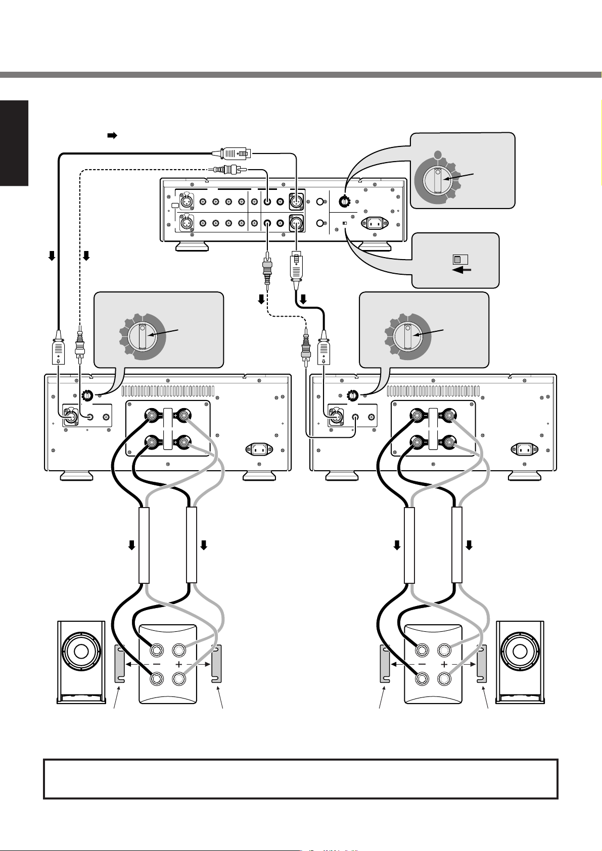
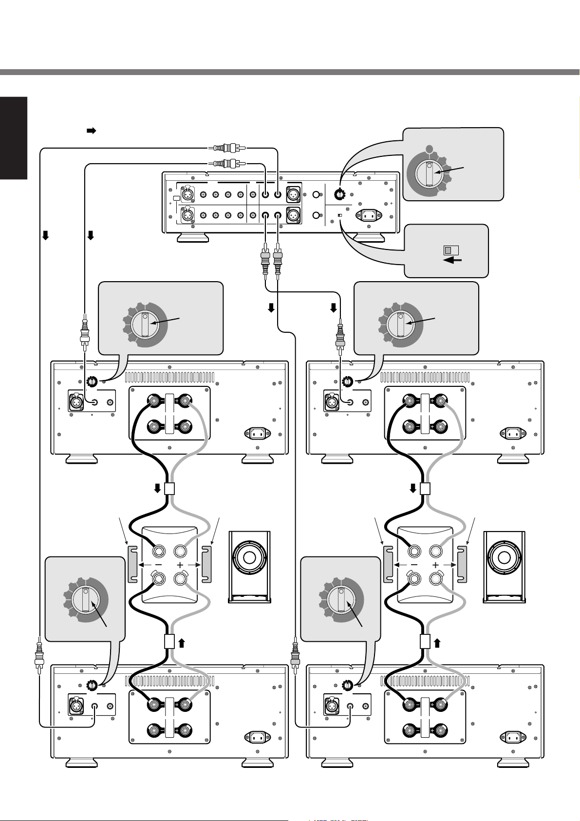
Connection 1 Stereo Bi-wiring Connection
ENGLISH
:Audio signal
REC
SC-7S1
BALANCED
SACD/CD
PUSH
PUSH
A
CH
BIAMP
PUSH
PUSH
B
CH
1 LINE
2
TAPE
PRE OUTINPUT
OUT
UNBALANCED
21
BALANCED
REMOTE
CONTROL
IN
OUT
or
(
)
ATTENUATOR
--3
--6
-
dB
0
Set to "0".
--9
--12
-
∞∞
(
)
-
ATTENUATOR
dB
0
--3
--6
--9
--12
-
∞∞
INPUT
BALANCED
UNBALANCED
PUSH PUSH
1 2
1
SPEAKERS
2
or
MA-9S1
for Lch
STEREO
BALANCED
ID NO.
1
2
Set to "1".
3
4
ID NO.
1
2
3
4
5
6
MODE
BI-AMP
5
6
MODE
BI-AMPSTEREO
Set to "STEREO".
(
)
ATTENUATOR
--3
--6
--9
--12
-
∞∞
(
)
-
ATTENUATOR
dB
0
--3
--6
--9
--12
-
∞∞
INPUT
UNBALANCED
1 2
-
dB
0
Setto"0".
MA-9S1
for Rch
1
SPEAKERS
2
Remove the short bar.
MF / HF
LF
Speaker
L ch
Remove the short bar.
MF / HF
LF
Remove the short bar. Remove the short bar.
Speaker
R ch
This connection can have options i,e, In-between 2 Un-balanced terminals or balanced terminals are
possible to wire SC-7S1 with MA-9S1.
4
Page 9
Connection 1 - 4 are recommended by Marantz for SC-7S1 with Marantz MA-9S1.
約
All Connection are based on speaker system complying with Bi-Wiring.
Please read instruction manual for SC-7S1for use. Name and Function ➔ P12
4. Connections
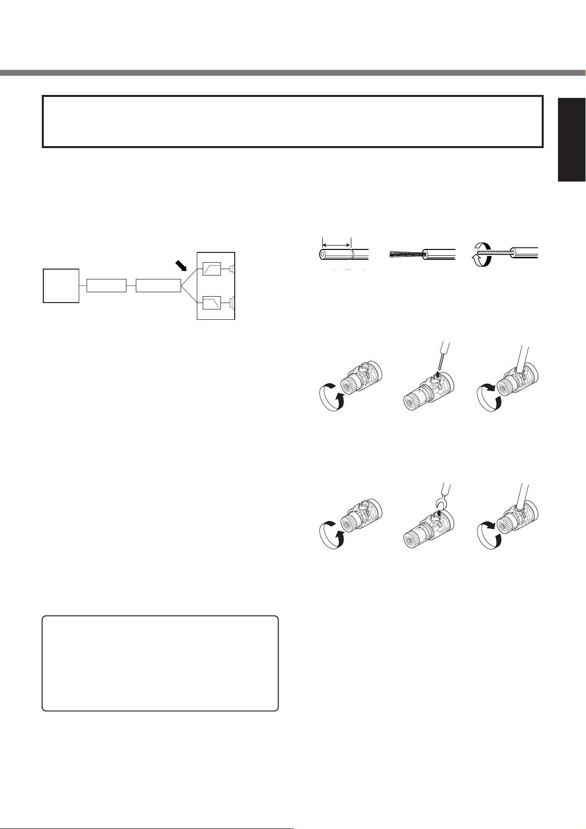
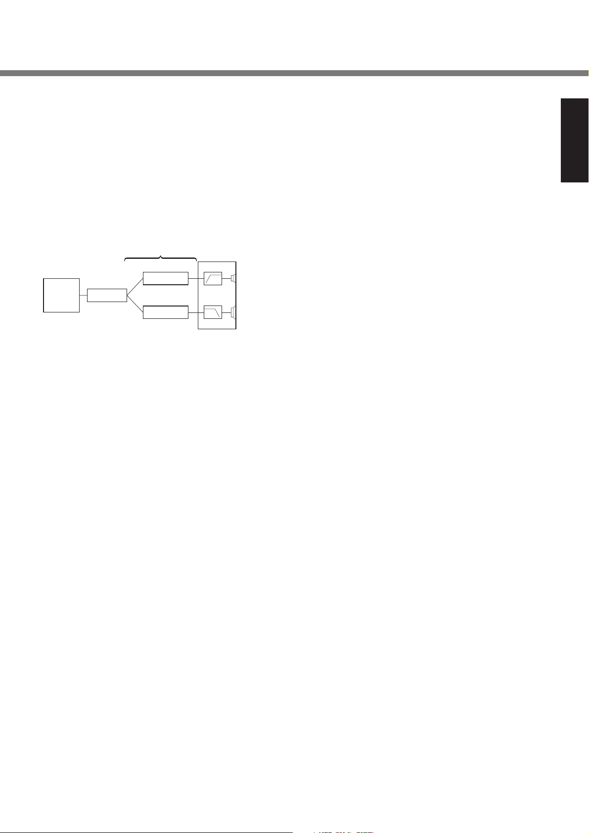
■ Bi-Wiring
The method to improve sound quality, by connecting speaker
code respectively to each terminal for Low and Mid/High
speakers. This method will reduce interference caused by
Low speaker unit to Mid/High speaker unit.
Speaker system
CD Player
Pre-Amp
Bi-Wiring
Power-Amp
Mid / High
speaker unit
Low speaker
unit
■ Wiring the speaker system
●
Speaker system doesn’t comply with the Bi-Wiring
Please connect either of speaker terminal 1 or 2. And please
use speaker system whose impedance is for 4 - 16Ω. If impedance is lower than 4Ω, protection circuit will work during
play.
●
Speaker system comply with the Bi-Wiring
Please connect both of speaker terminal 1 and 2. And please
use speaker system whose impedance is for 4 - 16Ω. If impedance is lower than 4Ω, protection circuit will work during
play.
■ Wiring speaker cable
●
Be careful not to short circuit in wiring speaker cables.
●
Peel off the corting of speaker cable as shown below.
Approx. 1 cm
1cm
コードの端から
Cut the corting
約1cmくらいの所
of cable.
にカッターで切り
込みをいれます
●
Wiring with speaker cable.
反時計方向に回
Turn counter-clock-
し、ゆるめます
wise to loosen.
●
Wiring with “Y” style terminal
Peel off the edge
コードの端の被ふく
of cable.
をむきとります
芯線を差し
Insert conductor
込みます
of cable.
Twist conductors.
芯線をよじります
時計方向に回
Turn clockwise
tighten.
してしめます
ENGLISH
to
●
Polarity of Speaker output terminal
Speaker terminals have positive (+ : Red) and negative (– :
White) polarity and speakers also have (+ & –) polarity.
In wiring, be sure to connect the terminals with the same polarity (+ and +, – and –).
CAUTION:
When connecting two pairs of speaker systems simultaneously, the impedance of each speaker system should
be no less than 8 ohm .
Connecting a speaker system with a lower impedance than
8 ohm may activate the protection circuitry and make normal stereo reproduction impossible.
反時計方向に回
Turn counter-clockwise to loosen.
し、ゆるめます
Yラグ端子を
Insert
conduc-
tor
.
差し込みます
時計方向に回
Turn clockwise
tighten.
してしめます
to
5
Page 10
UNBALANCED
BALANCED
SPEAKERS
UNBALANCED
BALANCED
SPEAKERS
REMOTE
PRE OUT
BIAMP
-
6
3
9
12
0
-
6
3
9
12
0
ID NO.
UNBALANCED
BALANCED
SPEAKERS
UNBALANCED
BALANCED
SPEAKERS
-
6
3
9
12
0
-
6
3
9
12
0
-
6
3
9
12
0
-
6
3
9
12
0
-
6
3
9
12
0
-
6
3
9
12
0
ID NO.
4. Connections
Connection 2 Stereo Bi-Amp connection.
ENGLISH
(Speaker system needs to comply with Bi-Amp connection)
:Audio signal
REC
INPUT
SC-7S1
ATTENUATOR
0
--3
--6
BALANCED
A
CH
BIAMP
B
CH
(
)
-
dB
Set to "0".
1 LINE 2
SACD/CD
PUSH
PUSH
PUSH
PUSH
TAPE
--9
--12
-
∞∞
for Lch MF/HF
(
)
-
ATTENUATOR
dB
0
--3
--6
--9
--12
-
∞∞
INPUT
BALANCED
UNBALANCED
PUSH PUSH
1 2
1
SPEAKERS
2
OUT
UNBALANCED
MA-9S1
PRE OUT
21
BALANCED
ID NO.
1
2
Set to "1".
3
4
REMOTE
ID NO.
CONTROL
1
2
IN
OUT
3
4
5
6
MODE
BI-AMPSTEREO
5
6
MODE
BI-AMPSTEREO
Set to "STEREO".
(
)
ATTENUATOR
--3
--6
--9
--12
-
∞∞
(
)
-
ATTENUATOR
dB
0
--3
--6
--9
--12
-
∞∞
INPUT
BALANCED
UNBALANCED
1 2
-
dB
0
Set to "0".
MA-9S1
for Rch MF/HF
1
SPEAKERS
2
ATTENUATOR
Remove the short bar.
Remove the short bar.
MF / HF
(
)
-
dB
0
--3
--6
LF
--9
--12
-
∞∞
Speaker
L ch
Set to "0".
MA-9S1
for Lch LF
(
)
-
ATTENUATOR
dB
0
--3
--6
--9
--12
-
∞∞
INPUT
BALANCED
UNBALANCED
PUSH PUSH
1 2
1
SPEAKERS
2
ATTENUATOR
Remove the short bar.
0
--3
--6
--9
--12
-
∞∞
Set to "0".
ATTENUATOR
0
--3
--6
--9
--12
-
∞∞
INPUT
BALANCED
UNBALANCED
1 2
Remove the short bar.
MF / HF
(
)
-
dB
LF
Speaker
R ch
MA-9S1
for Rch LF
(
)
-
dB
1
SPEAKERS
2
6
Page 11
Enhance the connection 1 to Bi-Amp connection, and drive
Low Frequency speaker unit and Mid / High Frequency
speaker unit by respective power Amplifiers.
■ Bi-Amp (connection)
The wiring method enhanced from Bi-Wiring, drive Low
speaker unit and Mid / High speaker unit by respective power
Amplifiers. Bi-Amp will lessen the burden on Power Amp impedance, so that back electromotive force between Low and
Mid/High signal can be lessen, we can expect drastic improvement on sound quality.
4. Connections
ENGLISH
CD Player
Bi-Amp Connection
Power-Amp
Pre-Amp
Power-Amp
Speaker system
Mid / High
speaker unit
Low speaker
unit
Caution :
In the event of this connection (Control Amp SC-7S1 is
<Stereo>mode), SC-7S1 and MA-9S1 can be wired by
Unbalanced only.
■ Wiring the speaker system
●
Please remove short bar of speaker terminal.
If short bar has not been remove, it will damage the power
amplifier.
●
Please use speaker system whose impedance is for 4 16Ω.
If impedance is lower than 4Ω, protection circuit will work
during play.
●
Speaker system has to comply with Bi-Amp connection.
If it didn’t, protection circuit will work and no sound signal
will come out. Or it will even damage the power amplifier.
7
Page 12
ATTENUATOR
UNBALANCED
BALANCED
∞
6
3
9
12
0
ATTENUATOR
UNBALANCED
BALANCED
∞
6
3
9
12
0
REMOTE
CONTROL
PRE OUT
INPUT
BALANCED
REC
OUT
TAPE
LINE
SACD/CD
BALANCED
BIAMP
UNBALANCED
OUT
ID NO.
ATTENUATOR
UNBALANCED
BALANCED
∞
6
3
9
12
0
ATTENUATOR
UNBALANCED
BALANCED
∞
6
3
9
12
0
REMOTE
CONTROL
PRE OUT
INPUT
BALANCED
REC
OUT
TAPE
SACD/CD
BALANCED
BIAMP
UNBALANCED
OUT
ID NO.
-
∞
6
3
9
12
0
ID NO.
-
∞
6
3
9
12
0
-
∞
6
3
9
12
0
ID NO.
-
∞
6
3
9
12
0
4. Connections
Connection 3 Stereo complete Bi-Amp connection.
ENGLISH
(Speaker system needs to comply with Bi-Amp connection)
ID NO.
1
2
3
Set to "1".
: Audio signal
or
REC
PRE OUT
OUT
UNBALANCED
21
BALANCED
REMOTE
CONTROL
OUT
INPUT
BALANCED
A
CH
BIAMP
B
CH
SC-7S1
for Lch
1 LINE
2
SACD/CD
PUSH
PUSH
PUSH
PUSH
TAPE
Bch can't be used.
or
(
)
-
dB
0
Set to "0". Set to "0".
1
SPEAKERS
2
ATTENUATOR
--3
--6
--9
--12
-
∞
(
)
-
ATTENUATOR
dB
0
--3
--6
--9
--12
--∞
INPUT
BALANCED
UNBALANCED
PUSH
1 2
4
5
6
ID NO.
1
2
IN
3
4
5
6
MODE
BI-AMPSTEREO
MODE
Set to "BI-AMP".
for Lch MF/HF
BI-AMPSTEREO
MA-9S1
As shown by connection 3 or 4,
Control Amp SC-7S1 can be controlled
through several sets in wiring by equipped
remote cable.
or
INPUT
BALANCED
A
CH
BIAMP
B
CH
SC-7S1
for Rch
BALANCED
1 LINE 2
SACD/CD
PUSH
PUSH
PUSH
PUSH
Bch can't be used.
ATTENUATOR
--6
--9
--12
(
)
-
ATTENUATOR
dB
0
--3
--6
--9
--12
--∞
INPUT
UNBALANCED
PUSH
1 2
TAPE
--3
-
∞
REC
PRE OUT
OUT
UNBALANCED
21
BALANCED
REMOTE
CONTROL
OUT
or
(
)
-
dB
0
1
SPEAKERS
2
ID NO.
1
Set to "2".
ID NO.
1
2
IN
3
4
5
6
MODE
BI-AMPSTEREO
MODE
BI-AMPSTEREO
Set to "BI-AMP".
MA-9S1
for Rch MF/HF
2
3
4
5
6
Remove the short bar. Remove the short bar. Remove the short bar. Remove the short bar.
MF
/
MF / HF
(
)
ATTENUATOR
--3
--6
--9
--12
-
∞
BALANCED
-
dB
0
LF
ATTENUATOR
--3
--6
--9
--12
-
∞
BALANCED
Speaker
L ch
Set to "0". Set to "0".
MA-9S1
for Lch LF
)
(
-
ATTENUATOR
dB
0
--3
--6
--9
--12
--∞
INPUT
UNBALANCED
PUSH
1 2
1
SPEAKERS
2
(
)
-
dB
0
)
(
-
ATTENUATOR
dB
0
--3
--6
--9
--12
--∞
INPUT
UNBALANCED
PUSH
1 2
HF
LF
Speaker
R ch
MA-9S1
for Rch LF
1
SPEAKERS
2
8
Page 13
4. Connections
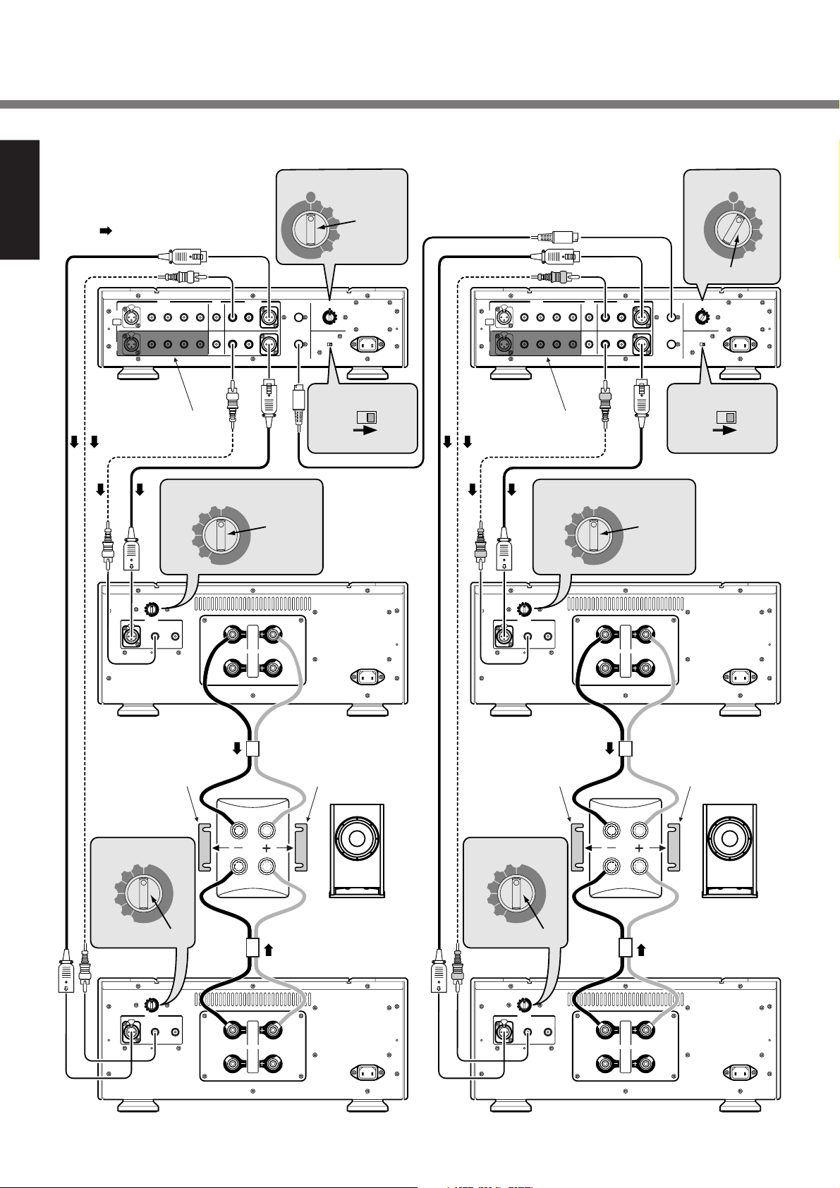
This connection can have options i,e, In-between 2 Un-balanced terminals or balanced terminals are
possible to wire SC-7S1 with MA-9S1.
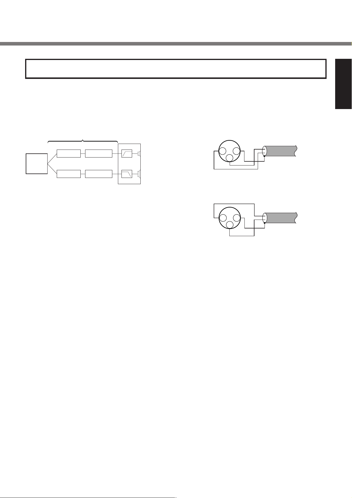
■ Complete Bi-Amp Connection
Enhance the connection 2, by having one more control Amp.
SC-7S1, this is a wiring <Complete Bi-Amp connection> which
separates Mid / High (MF/HF) signal and Low (LF) signal from
Pre-Amp section.
Complete Bi-Amp connection
Pre-Amp
CD Player
Pre-Amp
Power-Amp
Power-Amp
In this event, SC-7S1 is used as Monaural Amps. And separate Left/Right channels from output terminal of CD players.
As a result, influences between L channel and R channel Mid
/ High signal and Low signal will be eliminated.
By connection with remote cabel, maiximamly 6 pcs can be
interlock operated.
Caution
In the event of setting mode switch as <Bi-Amp>, B channel input terminals can’t be used.
Speaker system
Mid / High
speaker unit
Low speaker
unit
■ Balanced terminal
q The balanced output connector uses a XLR connector.
w The XLR connector for professional use is internally
wired in either of the following two systems.
1. USA system (Pin 2 = COLD, Pin 3 = HOT)
COLD
21
HOT
2. European system (Pin 2 = HOT, Pin 3 = COLD)
21
HOT
COLD
e The MA-9S1 uses the USA system of 1.
When a preamp or main amplifier adopting the European
system is connected using a cable with XLR balanced
connectors, the reproduced signal may be inverted of
phase.
In this case, correct the wiring of the one of the XLR connectors on the extremities of the cable to the USA system
by exchanging the connections of pins 2 and 3. This will
make it possible to play the signal with the correct phase.
GND
3
GND
3
ENGLISH
9
Page 14
4. Connections
■ Installing the SACD multi-channel
ENGLISH
audio speakers
In order to enjoy SACD multi-channel sound with the best
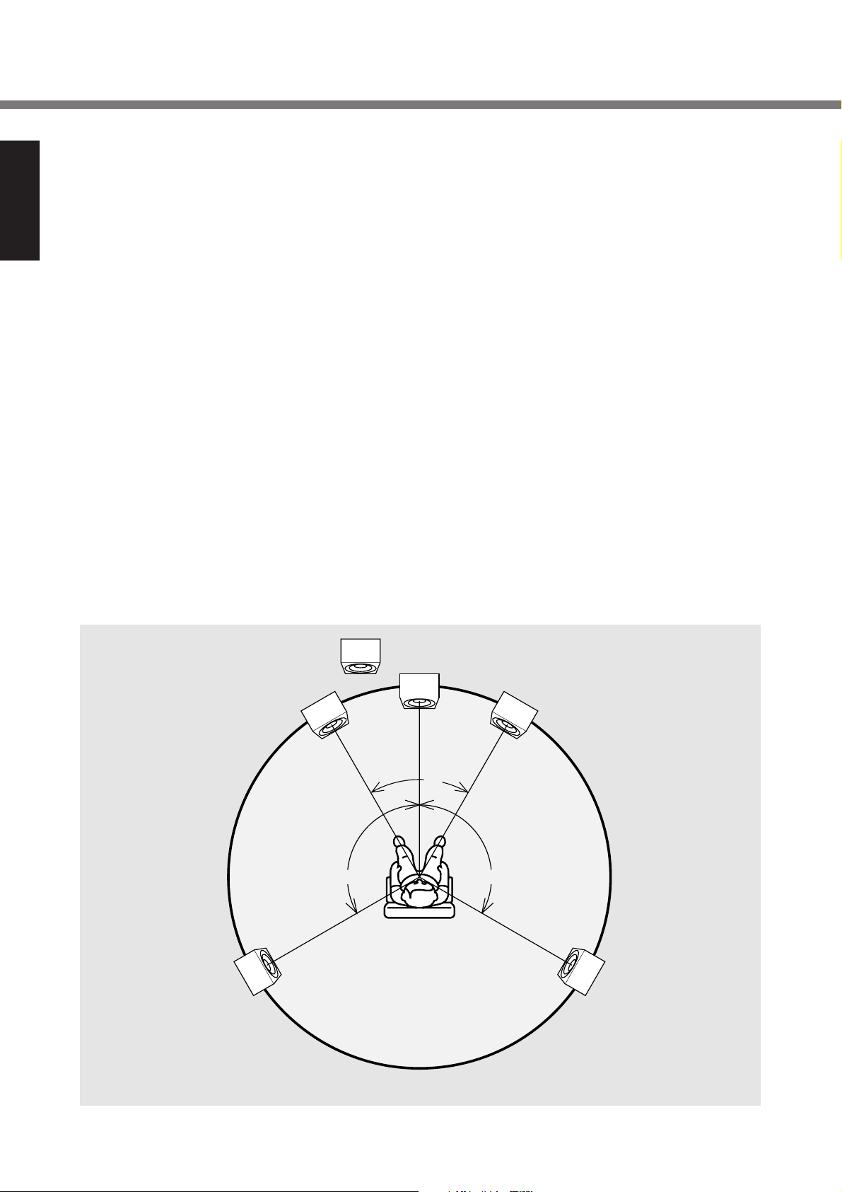
possible acoustics, it is recommended that the speaker systems be laid out in compliance with the ITU-R BS.775-1 recommendation which is a standard formulated by the International Telecommunication Union (ITU).
SACD multi-channel discs are recorded and mixed in such a
way that they will achieve the optimum effects when the
speaker systems are laid out as per the ITU-R BS.775-1 recommendation.
●
On SACD multi-channel discs, the music signals are basically recorded using 5 channels (or 3, 4 or 6 channels
in some cases). In some instances, however, LFE (for
the sub woofer) is recorded as a sixth channel.
Each disc indicates how many channels have been recorded on it.
●
The basic settings are 3 speakers for front and 2 for back
since multi-channel discs have basically 5 channels
The 2-front, 1-center, and 2-surround speakers should
be set on the circle from the listening point as shown
below.
When you use different sizes of speakers, please adjust
the volume balances.
●
The location of the sub-woofer in the picture is just to you
a patter of settings. Sub-woofer can be located any place
in your room. (See the users manual of your sub-woofer.)
■ ITU (International Telecommunication Union)
The ITU is a special organization of the United Nations. It
consists of a number of organs, one of which is the Radio
Broadcasting Section.
ITU-R BS in the recommendation which consists of standards
relating to broadcasting (audio) operations, one of which is
the ITU-R BS.775-1 which governs “multi-channel stereo
sound systems.”
Front speaker
Rear speaker
(Left Surround)
Sub-woofer
(Left)
approx. 110° approx. 110°
Center
speaker
60°
Reference listening
position
Front speaker
(Right)
Rear speaker
(Right Surround)
10
Page 15
ATTENUATOR ATTENUATOR
(
-
dBdB
)
UNBALANCEDUNBALANCED
BALANCEDBALANCED
INPUT
1 2
SPEAKERSSPEAKERS
2
1
REMOTE
CONTROL
PRE OUTINPUT
BALANCED
REC
OUT
TAPE
1 LINE 2
SACD/CD
BALANCED
A
BI-BI-
AMPAMP
21
UNBALANCED
IN
OUT
MODE
BI-AMPSTEREO
6
5
4
3
2
CH
B
CH
PUSH
PUSH
--
∞∞
--
66
--
33
--
99
--
1212
00
ID NO.ID NO.
PUSH
PUSH
PUSH
1
ATTENUATOR ATTENUATOR
(
-
dB
)
UNBALANCEDUNBALANCED
BALANCEDBALANCED
INPUTINPUT
1 2
SPEAKERSSPEAKERS
2
1
ATTENUATOR ATTENUATOR
(
-
dB
)
UNBALANCEDUNBALANCED
BALANCEDBALANCED
INPUTINPUT
1 2
SPEAKERSSPEAKERS
2
1
REMOTE
CONTROL
PRE OUTINPUTINPUT
BALANCEDBALANCED
RECREC
OUTOUT
TAPETAPE
1 LINE 2
SACD/CDSACD/CD
BALANCEDBALANCED
A
BIAMPAMP
21
UNBALANCEDUNBALANCED
IN
OUTOUT
MODE
BI-AMPSTEREO
6
5
4
3
2
CH
B
CH
PUSH
PUSH
--
∞∞
--
66
--
33
--
99
--
1212
00
--
∞∞
--
66
--
33
--
99
--
1212
00
ID NO.ID NO.
PUSH PUSH
PUSH
PUSH
1
ATTENUATOR
(
-
dB
)
UNBALANCEDUNBALANCED
BALANCEDBALANCED
INPUT
1 2
SPEAKERSSPEAKERS
2
1
ATTENUATOR ATTENUATOR
(
-
dB
)
UNBALANCEDUNBALANCED
BALANCEDBALANCED
INPUT
1 2
SPEAKERSSPEAKERS
2
1
REMOTE
CONTROL
PRE OUTINPUT
BALANCED
REC
OUT
TAPE
1 LINE 2
SACD/CD
BALANCED
A
BI-BI-
AMPAMP
21
UNBALANCED
IN
OUT
MODE
BI-AMPSTEREO
6
5
4
3
2
CH
B
CH
PUSH
PUSH
--
∞∞
--
66
--
33
--
99
--
1212
00
--
∞∞
--
66
--
33
--
99
--
1212
00
ID NO.ID NO.
PUSH PUSH
PUSH
PUSH
1
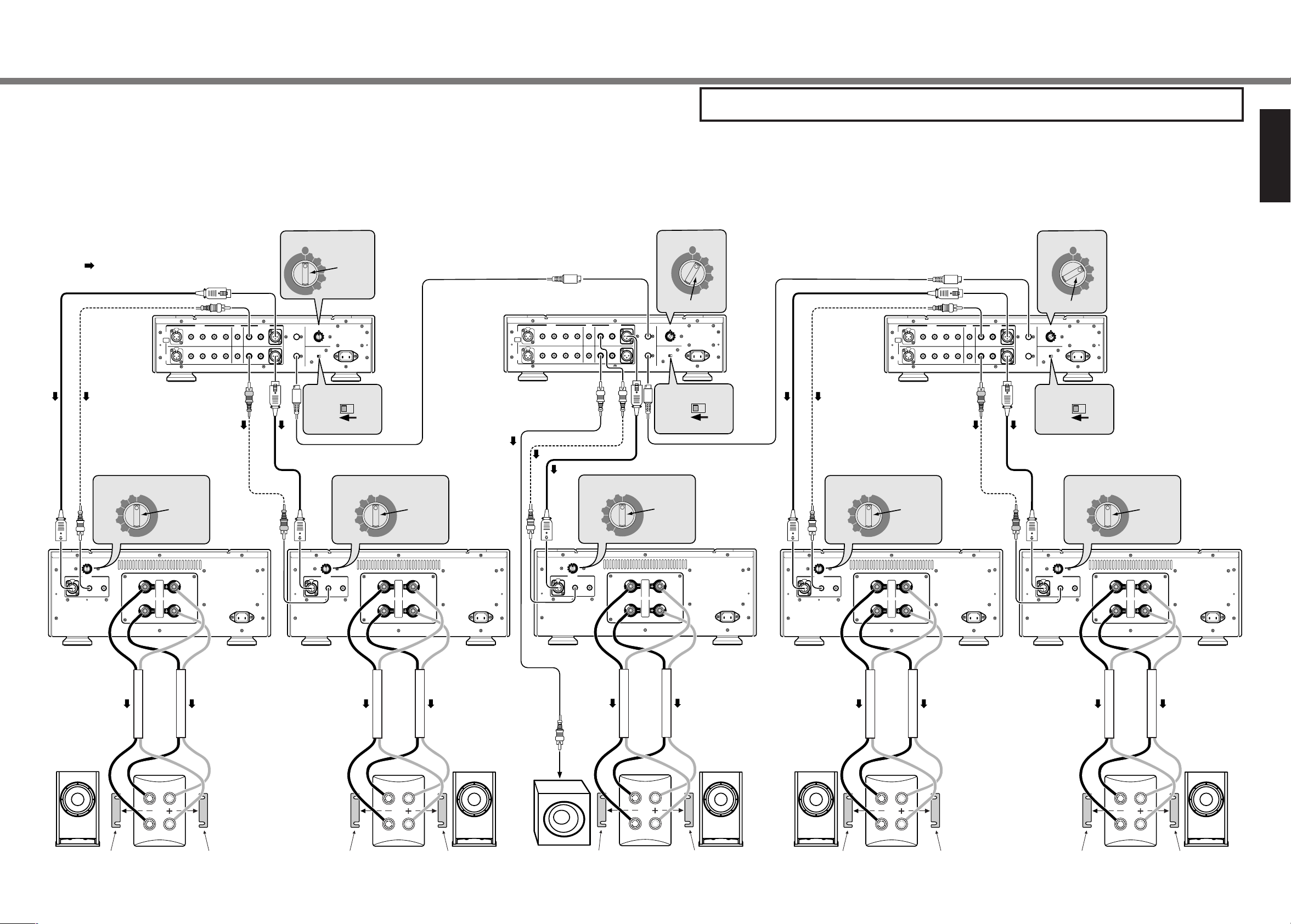
Front L/Rch
Front center/
Subwoofer
Surround
L/Rch
SC-7S1 SC-7S1 SC-7S1
MA-9S1
for Surround Lch
MA-9S1
for Surround Rch
Speaker
Surround R ch
Speaker
Surround L ch
Speaker
Front center
Speaker
Front Rch
Speaker
Front Lch
Active (Powered)
Subwoofer
MA-9S1
for Front center
MA-9S1
for Front Rch
MA-9S1
for Front Lch
Remove the short bar. Remove the short bar. Remove the short bar. Remove the short bar.
Remove the short bar.Remove the short bar.Remove the short bar.Remove the short bar. Remove the short bar.
Remove
the short bar.
MF / HF
LF
MF / HF
LF
MF / HF
LF
MF / HF
LF
MF / HF
LF
:Audio signal
or
or
or
or
or
ATTENUATOR
(
-
dB
)
--
∞∞
--
66
--
33
--
99
--
1212
00
ATTENUATOR
(
-
dB
)
--
∞∞
--
66
--
33
--
99
--
1212
00
ATTENUATOR
(
-
dB
)
--
∞∞
--
66
--
33
--
99
--
1212
00
ATTENUATOR
(
-
dB
)
--
∞∞
--
66
--
33
--
99
--
1212
00
ATTENUATOR
(
-
dB
)
--
∞∞
--
66
--
33
--
99
--
1212
00
MODE
6
5
4
3
2
ID NO.ID NO.
1
BI-AMPSTEREO
MODE
BI-AMPSTEREO
MODE
BI-AMPSTEREO
6
5
4
3
2
ID NO.ID NO.
1
6
5
4
3
2
ID NO.ID NO.
1
Set to "1".
Set to "STEREO". Set to "STEREO". Set to "STEREO".
Set to "2".
Set to "3".
Set to "0".Set to "0".Set to "0".Set to "0". Usually
set to "0".
4. Connections
Connection 4 5.1ch multi-channel connection
This connection can have options i,e, In-between 2 Un-balanced terminals or balanced terminals are
possible to wire SC-7S1 with MA-9S1.
This connection is standard for Multi-channel sound source. Realize the high quality sound acoustic for the professional Home
theatre and pure multi channel SACD. The whole system 5.1 ch is controlled by 3 unit of SC-7S1 connected operation.
The system can be enhanced to
●
<3 unit of SC-7S1 + 10 unit of MA-9S1 + Active sub-woofer>
●
<6 unit of SC-7S1 + 10 unit of MA-9S1 + Active sub-woofer>
■ Wiring speaker system
Please refer to <Wiring speaker system> p.5 of connection 1.
Caution
●
In case Active (powered) sub-woofer is used for LFE, please set-up wiring after perusal of Instruction manual.
LFE (Low Frequency Effect) is the channel for Low Frequency only.
●
In case Passive sub-woofer is used for LFE, Monaural power Amp such as MA-9S1 is required to drive it.
ENGLISH
11
Page 16

5. Name and function
METER OFF
OFF
ON
powerpower
monauralmonaural
power amplifier ma-9s1
BALANCEDUNBALANCED-2
INPUT
SELECTOR
1
wqt
re
ATTENUATOR
(
-
dB
)
UNBALANCED
BALANCED
INPUT
1
2
SPEAKERS
2
1
AC IN
11 COLDCOLD
33 HOTHOT
((
++
))
22 COLDCOLD
((--))
BALANCED CONNECTIONBALANCED CONNECTION
--
66
--
33
--
99
--
1212
00
PUSHPUSH
ui o !0
y
Front panel
ENGLISH
Rear panel
q Power switch
Press the power switch to turn the power on/off. When the
power is on, the power indicator e will illuminated.
w Input selector
This knob to select input source from Pre-Amp.
e Power indicator
The power indicator lights while the power switch is on.
r Level meter
The meter is used to check output power.
Meter indication vs Output power
Indicated level (dB) 8ΩLoad(W) 4ΩLoad(W)
0 300 600
–10 30 60
–20 3 6
–30 0.3 0.6
–40 0.03 0.06
t Meter off switch
This switch is used to turn on/off the level meter and internal
light of level meter.
y ATT (Attenuator)
The knob is to attenuate input level.
Initial set up is 0dB.
u Balanced input terminal
Connect to the Balanced output terminal of Pre-Amp.
i Unbalanced input terminal 1, 2
Connect to the Unbalanced output terminal of Pre-Amp.
o Speaker output terminal
Connect your speaker system to these terminals.
Speaker cable wiring → p.5
!0 AC IN socket
Connect to a household power outlet.
12
Page 17

6. Specification
■ Specification
Power Output (20Hz - 20kHz) ................................. 300W (8Ω Load)
600W (4Ω Load)
T.H.D. (20Hz - 20kHz, 8Ω Load) ............................................. 0.01%
Frequency response (1W, 8Ω Load) .......................... 3 Hz - 120 kHz
(+0, –3dB)
Dumping factor ........................................................................... 200
(20Hz - 20kHz, 8Ω Load)
Input sensitibity/ Input impedance .............. 1.7V / 20kΩ (Balanced)
1.7V / 20kΩ (Unbalanced)
S/N (IHF-A) .......................................................... 120 dB (Balanced)
120 dB (Unbalanced)
Attenuation ................................................ 0, –3, –6, –9, –12, – ∞ dB
Power requirement (MA 9 S1/N1G) ........................ AC 230V 50Hz
(MA 9S1/U1G) ......................... AC 120V 60Hz
Power Consumption (MA 9S1/N1G) .......................... 500 W (3.2 A)
(MA 9S1/U1G) .......................... 500 W (5.8 A)
1200 W (Output: 4Ω, 600W)
Dimensions ................................................................ Width 459 mm
Height 198 mm
Depth 451 mm
Weight ................................................................................... 35.8 kg
■ Dimensions Unit : mm
8
ENGLISH
20
459
198 451
7. Block diagram
UNBALANCED
12
3
INPUT
1
BALANCED
2
INPUT
SELECTOR
ATT
ATT
18
I/V
I/V
SPEAKER
OUTPUT
I/V
I/V
PROTECT
SOFT
START
REGULATOR
FINAL STAGE
INPUT / DRIVE STAGE
METER / PROTECT
13
Page 18

8. Trouble shooting
9. Maintenance
Should faults occur, in many cases it is not necessary to con-
ENGLISH
sult your dealer or a Marantz technical service department.
On the basis of the following checks you will be able to rectify
a number of faults yourself without difficulty.
If the fault cannot be remedied after the following checks,
please consult your dealer or nearest Marantz service agent.
The unit does not turn ON
1. Is the power cable securely plugged into an AC outlet?
Sound is not coming from the speakers
1. Has the wrong input source been selected with the INPUT SELECTOR on the front panel?
2. Is the ATTENUATOR switch set to
3. Are speaker cables properly connected to the speaker
system?
4. Is the connection cable properly connected to the control (pre) amplifier?
5. Is the control (pre) amplifier or input source wrongly set?
6. Are you using the player in the wrong way?
7. The protective circuit of this unit may have worked. Shut
power OFF, wait 1 minute or more, then reactivate the
power.
-∞ on the rear panel?
The section describes the care and maintenance tasks that
must be performed to optimize the operation of your Marantz
equipment.
●
Cleaning of equipment external surfaces
The exterior finish of your unit will last indefinitely with proper
care and cleaning, Never use scouring pads, steel wool,
scourging powders or harsh chemical agents (e.g., lye solution), alcohol, thinner, benzine, insecticide or other volatile
substances as these wil mar the finish of the equipment. Likewise, never use cloths containing chemical substances. If the
equipment get dirty, wipe the external surfaces with a soft,
lint-free cloth.
If the equipment becomes heavily soiled:
• dilute some washing up liquid in water, in a ratio of one
part detergent to six parts water.
• dip a soft, lint free in the solution and wring the it is damp.
• wipe the equipment with the damp cloth.
• dry the equipment by wiping it with a dry cloth.
■ About the Protective Circuit
This unit incorporates a protective circuit that protects the
amplifier circuit and speaker system against damage. If the
protective circuit works, the meter lights go out and the sound
is muted. (Pressing the METER OFF switch also douses the
meter lights.) This protective circuit works in the following cases.
●
At power ON
When power is activated, the protective circuit works and
mutes the sound for about 8 seconds until the amplifier circuit stabilizes. Once the amplifier circuit stabilizes, the protective circuit releases and muting is canceled. At the same
time, the meter lights turn ON.
●
If overcurrent flows to the amplifier circuit
(Overcurrent protection)
If overcurrent flows to the amplifier circuit because of excessive signal input or if the unit is used with speakers of less
than 4 Ω impedance connected to it, overcurrent is detected
and the protective circuit works. The protective circuit also
works if the speaker cables are accidentally shorted.
If the protective circuit works, the meter lights go out, therefore you can know whether or not that is the problem by checking the meter lights.
If it has worked, shut power OFF, wait 1 minute or more, then
reactivate the power.
●
Repairs
Only the most competent and qualified service technicians
should be allowed to service the factory-trained warranty station personnel have the knowledge and special facilities
needed for repair and calibration of this precision equipment.
After the warranty period has expired, repairs will be performed for a charge if the equipment can be returned to normal operation.
In the event of difficulty, refer to your dealer or write directly to
the nearest location to you that is listed on the Marantz Authorized Service Station list. If writing, please include the model
and serial number of the equipment together with a full description of what you think is abnormal about the equipment's
behaviour.
●
If the amplifier overheats
In the following cases, the amplifier will overheat and the protective circuit will work .
• If the unit is used with the ventilation blocked or obstructed
• If speakers of less than 4 Ω impedance are used
• If the unit is used for an extended period of time under
excessive signal input.
14
Page 19

Table des matiéres
1. Instructions pour l’utilisation............................................................................................... 2
Avant-propos............................................................................................................................................................................ 2
Réglage pour le fonctionnement de l’appareil sur secteur ...................................................................................................... 2
Druits d' auteur .........................................................................................................................................................................2
Précautions .............................................................................................................................................................................. 2
2. Accessoires ........................................................................................................................... 2
3. Principales caractéristiques de l’appareil .......................................................................... 3
4. Connections .......................................................................................................................... 4
Raccordement 1 Double raccordement stéréo ................................................................................................................ 4
Double raccordement ........................................................................................................................................................... 5
Raccordement des enceintes ............................................................................................................................................... 5
Raccordement du câble d’enceinte ..................................................................................................................................... 5
Raccordement 2 Raccordement Bi-Amp stéréo .............................................................................................................. 6
(Les enceintes doivent prendre en charge le raccordement Bi-Amp)
Bi-Amp (raccordement) ........................................................................................................................................................ 7
Raccordement des enceintes ............................................................................................................................................... 7
Raccordement 3 Raccordement Bi-Amp stéréo complet. .............................................................................................. 8
(Les enceintes doivent prendre en charge le raccordement Bi-Amp.)
Raccordement Bi-Amp complet ........................................................................................................................................... 9
A propos des bornes balanced (Equilibrees) ...................................................................................................................... 9
Installer les enceintes audio multicanales SACD ............................................................................................................. 10
ITU (International Telecommunication Union )(Union Internationale de Télécommunication) ........................................... 10
Raccordement 4 Raccordement à canaux multiples 5,1 canaux ................................................................................. 11
Raccordement des enceintes ............................................................................................................................................. 11
FRANÇAIS
5. Nomenclature et fonctions ................................................................................................. 12
6. Fiche technique ................................................................................................................... 13
7. Schéma fonctionnel ............................................................................................................ 13
8. Dépistage des pannes ........................................................................................................ 14
À propos du circuit de protection ....................................................................................................................................... 14
9. Entretien............................................................................................................................... 14
1
Page 20

1. Instructions pour l’utilisation
2. Accessoires
■
Avant-propos
Lire attentivement ce chapitre avant de procéder au
branchement de l’appareil sur le secteur.
■ Réglage pour le fonctionnement de
l’appareil sur secteur
FRANÇAIS
FRANÇAIS
Cet appareil Marantz été conçu pour respecter les exigences
de votre région en matière d’alimentation secteur et de
sécurité.
Le MA 9S1/N1G doit être alimenté sur secteur 230 V.
Le MA 9S1/U1G doit être alimenté sur secteur 120 V.
■
Druits d' auteur
L’enregistrement et la lecture de certaines informations
sonores nécessitent une autorisation. Pour de plus amples
renseignements, consultez:
— La loi de 1956 sur les Copyright.
— La loi de 1972 sur les interprétations dramatiques et
musicales.
— Les décrets et règlements ultérieurs qui s’y rapportent.
Veuillez vous assurer que les accessoires suivants sont tous
présents dans la boîte.
●
Cordon d’alimentation
(MA 9S1/N1G) (MA 9S1/U1G)
●
Mode d’emploi (le présent manuel)
■
Précautions
Les précautions suivantes doivent être prises pour utiliser
l’appareil.
●
Précautions Générales
Lors de l’installation de l’appareil, vérifiez que :
— les orifices d’aération ne sont pas couverts
— l’air peut circuler librement autour de l’appareil
— il est placé sur une surface sans vibration
— il ne sera pas exposé à des interférences provenant d’une
source extérieure
— il ne sera pas exposé à une chaleur, un froid, une humidité
ou une poussière excessive
— il ne sera pas exposé aux rayons directs du soleil
— il ne sera pas exposé à des décharges électrostatiques
Ne placez jamais un objet lourd sur l’appareil.
Si un corps étranger ou de l’eau pénètre dans l’appareil,
prenez contact avec le distributeur ou le centre de service le
plus proche.
Ne débranchez pas l’appareil en tirant sur le cordon secteur,
mais saisissez la prise.
Il est recommandé, lorsque vous sortez ou pendant un orage,
de débrancher l’appareil de l’alimentation secteur.
2
Page 21

3. Principales caractéristiques de l’appareil
●
Le concept : capacité de fourniture immédiate
du courant
La performance de deux amplificateurs de même puissance
peut varier suivant leur capacité respective de fournir le courant.
La capacité d’un amplificateur de puissance de fournir le
courant dépend du degré d’instantanéité de l’alimentation
électrique.
C’est pour cette raison que nous avons complètement
réorganisé l’alimentation électrique du MA-9S1, de façon à
lui donner une véritable capacité de fourniture immédiate du
courant trois fois supérieure à tout produit Marantz antérieur.
●
Amplificateur de puissance monaural
entièrement symétrique
Pour minimiser les effets du puissant «courant réfléchi» émis
par les haut-parleurs, le circuit de l’amplificateur de puissance
est composé de deux amplificateurs qui permettent une amplification du gain de tension de 23 dB dans un circuit à 3
composants parallèles symétriques, pour un amplificateurtampon final de 6 dB.
●
HDAM SA
L’impédance de réaction du circuit de réaction d’intensité a
été réduite le plus possible, afin de permettre une plus grande
rapidité.
Nous avons développé un nouveau module HDAM (Module
d’Amplificateur Haute Définition) séparé fonctionnant comme
tampon pour l’amplificateur.
●
Système inductif d’entrée
L’alimentation électrique du système inductif d’entrée adopté
pour l’amplificateur à gain de tension a peu d’ondulations et
est maintenue lors des changements de charge.
Cela peut prévenir la génération de bruit par l’amplificateur
et réduire le bruit émis par l’enroulement primaire, résultant
en une alimentation électrique très nette.
FRANÇAIS
●
Amplificateur à ultra-basse impédance
Le bloc d’alimentation de l’amplificateur-tampon, qui permet
une capacité élevée de fourniture du courant, atteint un très
bas niveau d’impédance grâce à l’utilisation d’un système
d’entrée capacitif.
Le transformateur de puissance à super bobine, les
condensateurs électrolytiques à basse impédance, le câblage
interne très gros et la carte de circuit imprimé épaisse
contribuent tous ensemble à fournir toute la puissance requise.
3
Page 22

SPEAKERS
INPUT
SPEAKERS
BALANCED
LINE
SACD/CD
BALANCED
UNBALANCED
OUT
BI-AMP
STEREO
-
6
3
9
12
0
-
6
3
9
12
0
ID NO.
-
6
3
9
12
0
-
6
3
9
12
0
ID NO.
4. Raccordements
Raccordement 1 Double raccordement stéréo
FRANÇAIS
: signal audio
REC
SC-7S1
BALANCED
SACD/CD
PUSH
PUSH
A
CH
BIAMP
PUSH
PUSH
B
CH
1 LINE
2
TAPE
PRE OUTINPUT
OUT
UNBALANCED
21
BALANCED
REMOTE
CONTROL
IN
OUT
ou
(
)
ATTENUATOR
--3
--6
--9
-
dB
0
Réglez
sur “0”
--12
-
∞∞
(
)
-
ATTENUATOR
dB
0
--3
--6
--9
--12
-
∞∞
INPUT
BALANCED
UNBALANCED
PUSH PUSH
1 2
1
SPEAKERS
2
MA-9S1
pour canal
gauche
ou
STEREO
BALANCED
ID NO.
1
2
3
Réglez
sur “1”
4
ID NO.
1
2
3
4
5
6
MODE
BI-AMP
5
6
MODE
BI-AMPSTEREO
Réglez sur “STEREO”
(
)
ATTENUATOR
--3
--6
--9
--12
-
∞∞
(
)
-
ATTENUATOR
dB
0
--3
--6
--9
--12
-
∞∞
INPUT
UNBALANCED
1 2
-
dB
0
Réglez
sur “0”
MA-9S1
pour canal
droit
1
SPEAKERS
2
Retirez la barre
de la masse
MF / HF
Enceinte
Canal gauche
LF
Retirez la barre
de la masse
Retirez la barre
de la masse
MF / HF
LF
Enceinte
Canal droit
Retirez la barre
de la masse
Ce raccordement comporte deux options possibles, à savoir : raccordement du SC-7S1 au MA-9S1 par
2 bornes asymétriques ou par 2 bornes symétriques.
4
Page 23

約
4. Raccordements
Les raccordements 1 à 4 sont recommandés par Marantz pour le raccordement d’un appareil SC-7S1 à
un appareil Marantz MA-9S1.
Tous ces raccordements nécessitent des enceintes prenant en charge le double raccordement.
Pour l’utilisation, veuillez lire le mode d’emploi du SC-7S1. Nomenclature et fonctions ➔ Page 12
■ Double raccordement
Cette méthode permet d’améliorer la qualité sonore, en
raccordant respectivement les deux fils du câble d’enceinte
aux bornes des enceintes de basse fréquence et de
fréquence moyenne/élevée. Cette méthode réduit
l’interférence causée par l’unité d’enceinte de basse
fréquence sur l’unité d’enceinte de fréquence moyenne/
élevée.
Enceinte
Lecteur CD
Double raccordement
Pré-ampli
Ampli de
puissance
Enceinte à fréquence
moyenne/élevé
Enceinte à fréquence
basse
■ Raccordement des enceintes
●
Les enceintes ne prennent pas en charge le
double raccordement
Raccordez la borne d’enceinte 1 ou 2. En utilisant des
enceintes d’une impédance de 4 à 16 Ω. Si l’impédance est
inférieure à 4 Ω, le circuit de protection s'activera pendant la
lecture.
●
Si des enceintes prenant en charge le double
raccordement sont utilisées
Raccordez les bornes d’enceinte 1 et 2. En utilisant des
enceintes d’une impédance de 4 à 16 Ω. Si l’impédance est
inférieure à 4 Ω, le circuit de protection s'activera pendant la
lecture.
■ Raccordement du câble d’enceinte
●
Prenez garde de court-circuiter les câbles d’enceinte en
les raccordant.
●
Retirez la gaine de vinyle du câble d’enceinte comme
indiqué ci-dessous.
Environ 1 cm
1cm
コードの端から
約1cmくらいの所
Coupez la gaine de
にカッターで切り
vinyle du câble.
込みをいれます
●
Raccordement avec un câble d’enceinte.
Tournez dans le sens
反時計方向に回
inverse des aiguilles
し、ゆるめます
d’une montre pour
desserrer.
●
Raccordement avec une fiche en “Y”
Retirez la gaine du
コードの端の被ふく
bout du câble.
をむきとります
Insérez le
芯線を差し
conducteur du
込みます
câble.
Torsadez les
芯線をよじります
conducteurs.
Tournez dans le
時計方向に回
sens des aigu-
してしめます
illes d’une montre
pour serrer.
FRANÇAIS
●
Caractéristique des bornes de sortie d’enceinte
Les bornes d’enceinte ont un pôle positif (+ : rouge) et un
pôle négatif (– : blanc) qui correspondent à la polarité des
enceintes (+ et –).
Lorsque vous effectuez les raccordements, assurez-vous de
raccorder ensemble les bornes de même polarité (+ avec +
et – avec –).
ATTENTION :
Lorsque vous raccordez simultanément deux paires
d’enceintes, l’impédance de chaque paire d’enceintes ne
doit pas être inférieure à 8 ohms.
Le raccordement d’une paire d’enceintes ayant une
impédance inférieure à 8 ohms peut activer le circuit de pro-
tection et rendre impossible une reproduction stéréo normale.
反時計方向に回
Tournez dans le sens
し、ゆるめます
inverse des aiguilles
d’une montre pour
desserrer.
Yラグ端子を
Insérez le
差し込みます
conducteur.
時計方向に回
Tournez dans le
してしめます
sens des aiguilles d’une montre
pour serrer.
5
Page 24

UNBALANCED
BALANCED
SPEAKERS
UNBALANCED
BALANCED
SPEAKERS
REMOTE
CONTROL
PRE OUT
BIAMP
-
6
3
9
12
0
-
6
3
9
12
0
ID NO.
UNBALANCED
BALANCED
SPEAKERS
UNBALANCED
BALANCED
SPEAKERS
-
6
3
9
12
0
-
6
3
9
12
0
-
6
3
9
12
0
-
6
3
9
12
0
-
6
3
9
12
0
-
6
3
9
12
0
ID NO.
4. Raccordements
Raccordement 2 Raccordement Bi-Amp stéréo.
(Les enceintes doivent prendre en charge le raccordement Bi-Amp.)
FRANÇAIS
: signal audio
REC
INPUT
SC-7S1
ATTENUATOR
0
--3
--6
--9
(
-
dB
BALANCED
A
CH
BIAMP
B
CH
)
Réglez
sur “0”
1 LINE 2
SACD/CD
PUSH
PUSH
PUSH
PUSH
TAPE
--12
-
∞∞
gauche Fréq. M/É
(
)
-
ATTENUATOR
dB
0
--3
--6
--9
--12
-
∞∞
INPUT
BALANCED
UNBALANCED
PUSH PUSH
1 2
1
SPEAKERS
2
PRE OUT
OUT
UNBALANCED
MA-9S1
pour canal
21
BALANCED
ID NO.
1
2
3
Réglez
sur “1”
REMOTE
ID NO.
CONTROL
1
2
IN
OUT
3
4
5
6
MODE
BI-AMPSTEREO
4
5
6
MODE
BI-AMPSTEREO
Réglez sur “STEREO”
(
)
ATTENUATOR
--3
--6
--9
--12
-
∞∞
(
)
-
ATTENUATOR
dB
0
--3
--6
--9
--12
-
∞∞
INPUT
BALANCED
UNBALANCED
1 2
-
dB
0
Réglez
sur “0”
MA-9S1
pour canal
droit Fréq. M/É
1
SPEAKERS
2
ATTENUATOR
Retirez la barre
de la masse
Retirez la barre
de la masse
Retirez la barre
de la masse
MF / HF
(
)
-
dB
0
--3
--6
LF
--9
--12
-
∞∞
Réglez sur “0” Réglez sur “0”
Enceinte
Canal gauche
MA-9S1
pour canal
gauche Fréq. B
(
)
-
ATTENUATOR
dB
0
--3
--6
--9
--12
-
∞∞
INPUT
BALANCED
UNBALANCED
PUSH PUSH
1 2
1
SPEAKERS
2
ATTENUATOR
0
--3
--6
--9
--12
-
∞∞
(
-
ATTENUATOR
dB
0
--3
--6
--9
--12
-
∞∞
INPUT
BALANCED
UNBALANCED
1 2
Retirez la barre
de la masse
MF / HF
(
)
-
dB
LF
Enceinte
Canal droit
MA-9S1
pour canal
droit Fréq. B
)
1
SPEAKERS
2
6
Page 25

Cela permet d’améliorer l’exemple 1 pour en faire un
raccordement Bi-Amp, de sorte que les amplificateurs de
puissance contrôlent respectivement les enceintes à basse
fréquence et les enceintes à fréquence moyenne/élevée.
■ Bi-Amp (raccordement)
Il s’agit d’une méthode améliorée de raccordement double,
avec laquelle les amplificateurs de puissance contrôlent
respectivement l’unité d’enceinte à basse fréquence et l’unité
d’enceinte à fréquence moyenne/élevée. Le raccordement
Bi-Amp réduit le fardeau imposé à l’impédance de
l’amplificateur de puissance, de sorte que la force
électromotrice de retour entre les signaux de basse fréquence
et les signaux de fréquence moyenne/élevée se trouve réduite,
d’où s’ensuit généralement une amélioration radicale de la
qualité sonore.
4. Raccordements
FRANÇAIS
Lecteur CD
Raccordement Bi-Amp
Ampli de
puissance
Pré-ampli
Ampli de
puissance
Enceinte
Enceinte à fréquence
moyenne/élevé
Enceinte à fréquence
basse
Attention
Dans cet exemple de raccordement (amplificateur de
commande SC-7S1 en mode <Stereo>), seul le
raccordement asymétrique est possible entre le SC-7S1
et le MA-9S1.
■ Raccordement des enceintes
●
Veuillez retirer la barre courte de la borne d’enceinte.
L’amplificateur de puissance sera endommagé si vous
ne retirez pas la barre de mise à la masse.
●
Veuillez utiliser des enceintes dont l’impédance est de 4
à 16 Ω.
Si l’impédance est inférieure à 4 Ω, le circuit de protec-
tion s’activera pendant la lecture.
●
Les enceintes doivent prendre en charge le raccordement
Bi-Amp. Sinon, le circuit de protection s’activera et aucun
signal sonore ne sera émis. Cela risque même
d’endommager l’amplificateur.
7
Page 26

ATTENUATOR
UNBALANCED
BALANCED
∞
6
3
9
12
0
ATTENUATOR
UNBALANCED
BALANCED
∞
6
3
9
12
0
REMOTE
CONTROL
PRE OUT
INPUT
BALANCED
REC
OUT
TAPE
LINE
SACD/CD
BALANCED
BIAMP
UNBALANCED
OUT
ID NO.
ATTENUATOR
UNBALANCED
BALANCED
∞
6
3
9
12
0
ATTENUATOR
UNBALANCED
BALANCED
∞
6
3
9
12
0
REMOTE
CONTROL
PRE OUT
INPUT
BALANCED
REC
OUT
TAPE
SACD/CD
BALANCED
BIAMP
UNBALANCED
OUT
ID NO.
-
∞
6
3
9
12
0
ID NO.
-
∞
6
3
9
12
0
-
∞
6
3
9
12
0
ID NO.
-
∞
6
3
9
12
0
4. Raccordements
Raccordement 3 Raccordement Bi-Amp stéréo complet.
(Les enceintes doivent prendre en charge le raccordement Bi-Amp.)
FRANÇAIS
ID NO.
1
2
3
Réglez
4
: signal audio
ou
REC
PRE OUT
OUT
UNBALANCED
21
ou
(
-
0
dB
BALANCED
REMOTE
CONTROL
IN
OUT
Réglez sur “BI-AMP” Réglez sur “BI-AMP”
)
Réglez
sur “0”
1
SPEAKERS
2
INPUT
BALANCED
A
CH
BIAMP
B
CH
SC-7S1
pour canal
gauche
SACD/CD
PUSH
PUSH
PUSH
PUSH
1 LINE
2
TAPE
Le côté canal
B n’est pas
disponible.
ATTENUATOR
--3
--6
--9
--12
-
∞
(
)
-
ATTENUATOR
dB
0
--3
--6
--9
--12
--∞
INPUT
BALANCED
UNBALANCED
PUSH
1 2
sur “1”
5
6
ID NO.
1
2
3
4
5
6
MODE
BI-AMPSTEREO
MODE
pour canal
gauche Fréq. M/É
BI-AMPSTEREO
MA-9S1
Tel qu’indiqué sur les raccordement 3 et 4,
l’amplificateur de commande SC-7S1 peut être
commandé via plusieurs appareils raccordés
avec les câbles de télécommande fournis.
ou
REC
PRE OUT
OUT
UNBALANCED
21
ou
(
-
0
1
SPEAKERS
2
INPUT
BALANCED
A
CH
BIAMP
B
CH
SC-7S1
pour canal
droit
SACD/CD
PUSH
PUSH
PUSH
PUSH
1 LINE 2
TAPE
Le côté canal
B n’est pas
disponible.
ATTENUATOR
--3
--6
--9
--12
-
∞
(
)
-
ATTENUATOR
dB
0
--3
--6
--9
--12
--∞
INPUT
BALANCED
UNBALANCED
PUSH
1 2
dB
BALANCED
)
REMOTE
CONTROL
Réglez
sur “0”
ID NO.
Réglez sur “2”
ID NO.
1
2
IN
3
4
5
6
OUT
MODE
BI-AMPSTEREO
MODE
1
2
3
4
5
6
BI-AMPSTEREO
MA-9S1
pour canal
droit Fréq. M/É
Retirez la barre
de la masse
MF / HF
(
)
ATTENUATOR
--3
--6
--9
--12
-
∞
Réglez sur “0” Réglez sur “0”
BALANCED
-
dB
0
LF
)
(
-
ATTENUATOR
dB
0
--3
--6
--9
--12
--∞
INPUT
UNBALANCED
PUSH
1 2
1
SPEAKERS
2
Retirez la barre
de la masse
Enceinte
Canal gauche
MA-9S1
pour canal
gauche Fréq. B
Retirez la barre
ATTENUATOR
--3
--6
--9
--12
-
∞
BALANCED
PUSH
de la masse
(
-
0
)
(
-
ATTENUATOR
dB
0
--3
--6
--9
--12
--∞
INPUT
UNBALANCED
1 2
dB
Retirez la barre
de la masse
MF
/
HF
)
LF
Enceinte
Canal droit
MA-9S1
pour canal
droit Fréq. B
1
SPEAKERS
2
8
Page 27

4. Raccordements
Ce raccordement comporte deux options possibles, à savoir : raccordement du SC-7S1 au MA-9S1 par
2 bornes asymétriques ou par 2 bornes symétriques.
■ Raccordement Bi-Amp complet
Cela permet d’améliorer l’exemple de raccordement 2, en
ajoutant un autre amplificateur de commande SC-7S1, formant
ainsi un <raccordement Bi-Amp complet> où les signaux de
fréquence moyenne/élevé (MF/HF) et les signaux de basse
fréquence sont séparés à partir de la section préamplificateur.
Raccordement Bi-Amp complet
Pré-ampli
Lecteur CD
Pré-ampli
Ampli de
puissance
Ampli de
puissance
Chacun des amplificateurs SC-7S1 est alors utilisé en tant
qu’amplificateur monaural. Ce raccordement sépare
également les canaux de droite et de gauche de la borne de
sortie des lecteurs CD. Il en résulte l’élimination des influences entre le canal gauche et le canal droit, ainsi qu’entre
les signaux de fréquence moyenne/élevée et les signaux de
basse fréquence.
Le raccordement au moyen de câbles de télécommande
permet d’utiliser jusqu’à six appareils en synchronisation.
Enceinte
Enceinte à fréquence
moyenne/élevé
Enceinte à fréquence
basse
■ A propos des bornes balanced
(Equilibrees)
q Le connecteur de sortie équilibré est de type XLR
w Le connecteur XLR à usage professionnel est câblé
de manière interne dans l'un des deux systèmes
suivants.
1. Système américain (Broche 2 = FROID, Broche 3 =
CHAUD)
COLD
21
HOT
2. Système européen (Broche 2 = CHAUD, Broche 3 =
FROID)
21
HOT
COLD
GND
3
GND
3
FRANÇAIS
Attention
Les bornes d’entrée du canal B ne peuvent pas être
utilisées lorsque le commutateur de mode est réglé sur
<Bi-Amp>.
e Le MA-9S1 utilise le système américain 1.
Lors du raccordement d'un préamplificateur ou d'un
amplificateur principal adoptant le système européen,
à l'aide d'un câble équipé de connecteurs XLR
équilibrés, la phase du signal reproduit risque d'être
inversée. Dans ce cas, corriger le câblage d'un des
connecteurs XLR aux extrémités du câble pour le
façonner selon le système américain, en échangeant
les connexions des broches 2 et 3. Cela permettra de
lire les signaux dans la phase correcte.
9
Page 28

4. Raccordements
■ Installer les enceintes audio
multicanales SACD
Pour profiter du son multicanal SACD avec la meilleure
acoustique possible, il est conseillé de configurer les
enceintes conformément à la recommandation ITU-R BS.7751 qui est une norme formulée par l’International Telecommunication Union (ITU).
FRANÇAIS
Les disques multicanaux SACD sont enregistrés et mixés de
sorte que pour obtenir les effets optimaux, il convient de
configurer les enceintes selon la recommandation ITU-R
BS.775-1.
• Sur les disques multicanaux SACD, les signaux musicaux
sont enregistrés avec 5 canaux (ou dans certains cas
avec 3, 4 ou 6 canaux). Cependant, dans certains cas,
LFE (pour le sub woofer) est enregistré comme un sixième
canal.
Chaque disque indique combien de canaux il comporte
• Le réglage de base est le suivant: 3 enceintes pour l’avant
et 2 pour l’arrière car en général les disques multicanaux
comporte 5 canaux.
Les 2 enceintes avant, celle du centre et les 2 surround
doivent être disposée en cercle par rapport au point
d’écoute comme le montre l’illustration ci-dessous.
Si vous utilisez des enceintes de tailles différentes, veuillez
ajuster les balances de volume.
• L’emplacement du subwoofer sur l’image est une question de réglages. Le subwoofer peut être placé à n’importe
quel endroit de la pièce. (Voir le manuel de l’utilisateur
du sub-woofer.)
■ ITU (International Telecommunication Union )
(Union Internationale de Télécommunication)
L’ITU est un organisme spécialisé faisant partie des Nations
Unies. Il se compose de différentes organisation dont la Radio Broadcasting Section (section de radio-diffusion).
ITU-R BS est une recommandation qui comporte des normes
en rapport avec les opérations de diffusion (audio), on trouve
par exemple l’ITU-R BS.775-1 qui régit les “systèmes sonores
multicanaux.”
Enceinte avant
Enceinte arrière
(surround gauche)
Subwoofer
(gauche)
Enceinte
centrale
60°
Environ 110° Environ 110°
Position d’écoute de
référence
Enceinte avant
(droite)
Enceinte arrière
(surround droite)
10
Page 29

ATTENUATOR ATTENUATOR
(
-
dBdB
)
UNBALANCEDUNBALANCED
BALANCEDBALANCED
INPUT
1 2
SPEAKERSSPEAKERS
2
1
REMOTE
CONTROL
PRE OUTINPUT
BALANCED
REC
OUT
TAPE
1 LINE 2
SACD/CD
BALANCED
A
BI-BI-
AMPAMP
21
UNBALANCED
IN
OUT
MODE
BI-AMPSTEREOSTEREO
6
5
4
3
2
CH
B
CH
PUSH
PUSH
--
∞∞
--
66
--
33
--
99
--
1212
00
ID NO.ID NO.
PUSH
PUSH
PUSH
1
ATTENUATOR ATTENUATOR
(
-
dB
)
UNBALANCEDUNBALANCED
BALANCEDBALANCED
INPUTINPUT
1 2
SPEAKERSSPEAKERS
2
1
ATTENUATOR ATTENUATOR
(
-
dB
)
UNBALANCEDUNBALANCED
BALANCEDBALANCED
INPUTINPUT
1 2
SPEAKERSSPEAKERS
2
1
REMOTE
CONTROL
PRE OUTINPUTINPUT
BALANCEDBALANCED
REC
OUT
TAPETAPE
1 LINELINE 2
SACD/CDSACD/CD
BALANCEDBALANCED
A
BIAMPAMP
21
UNBALANCED
IN
OUT
MODE
BI-AMPSTEREO
6
5
4
3
2
CH
B
CH
PUSH
PUSH
--
∞∞
--
66
--
33
--
99
--
1212
00
--
∞∞
--
66
--
33
--
99
--
1212
00
ID NO.ID NO.
PUSH PUSH
PUSH
PUSH
1
ATTENUATOR
(
-
dB
)
UNBALANCEDUNBALANCED
BALANCEDBALANCED
INPUT
1 2
SPEAKERSSPEAKERS
2
1
ATTENUATOR ATTENUATOR
(
-
dB
)
UNBALANCEDUNBALANCED
BALANCEDBALANCED
INPUT
1 2
SPEAKERSSPEAKERS
2
1
REMOTE
CONTROL
PRE OUTINPUT
BALANCED
REC
OUT
TAPE
1 LINE 2
SACD/CD
BALANCED
A
BI-BI-
AMPAMP
21
UNBALANCED
IN
OUT
MODE
BI-AMPSTEREO
6
5
4
3
2
CH
B
CH
PUSH
PUSH
--
∞∞
--
66
--
33
--
99
--
1212
00
--
∞∞
--
66
--
33
--
99
--
1212
00
ID NO.ID NO.
PUSH PUSH
PUSH
PUSH
1
Canalavant
gauche/droit
Avant central/
Subwoofer
Canalsurround
gauche/droit
SC-7S1 SC-7S1 SC-7S1
MA-9S1
pour canal
surround gauche
MA-9S1
pour canal
surround droit
Enceinte canal
surround droit
Enceinte canal
surround gauche
Enceinte avant
centrale
Enceinte canal
avant droit
Enceinte canal
avant gauche
Subwoofer actif
(alimenté)
MA-9S1
pour avant
central
MA-9S1
pour canal
avant droit
MA-9S1
pour canal
avant gauche
Retirez la barre
de la masse
Retirez la barre
de la masse
Retirez la barre
de la masse
Retirez la barre
de la masse
Retirez la barre
de la masse
Retirez la barre
de la masse
Retirez la barre
de la masse
Retirez la barre
de la masse
Retirez la barre
de la masse
Retirez la barre
de la masse
MF / HF
LF
MF / HF
LF
MF / HF
LF
MF / HF
LF
MF / HF
LF
: signal audio
ou
ou
ou
ou
ou
ATTENUATOR
(
-
dB
)
--
∞∞
--
66
--
33
--
99
--
1212
00
ATTENUATOR
(
-
dB
)
--
∞∞
--
66
--
33
--
99
--
1212
00
ATTENUATOR
(
-
dB
)
--
∞∞
--
66
--
33
--
99
--
1212
00
ATTENUATOR
(
-
dB
)
--
∞∞
--
66
--
33
--
99
--
1212
00
ATTENUATOR
(
-
dB
)
--
∞∞
--
66
--
33
--
99
--
1212
00
MODE
6
5
4
3
2
ID NO.ID NO.
1
BI-AMPSTEREO
MODE
BI-AMPSTEREO
MODE
BI-AMPSTEREO
6
5
4
3
2
ID NO.ID NO.
1
6
5
4
3
2
ID NO.ID NO.
1
Réglez
sur “0”
Réglez
sur “1”
Réglez sur “2”
Réglez sur “3”
Réglez sur “STEREO”
Réglez sur “STEREO”
Réglez sur “STEREO”
Réglez
sur “0”
Réglez
sur “0”
Réglez
sur “0”
Réglez
sur “0”
4. Raccordements
Raccordement 4 Raccordement à canaux multiples 5,1 canaux
Ce raccordement comporte deux options possibles, à savoir : raccordement du SC-7S1 au MA-9S1
par 2 bornes asymétriques ou par 2 bornes symétriques.
Il s’agit de l’exemple standard pour les sources sonores multicanal. Il procure une qualité sonore supérieure pour le Home
Theater professionnel et une grande pureté de son multicanal SACD. L’ensemble du système à 5.1 canaux est commandé en
liaison par les 3 appareils SC-7S1 raccordés.
Il est possible d’améliorer ce système comme suit :
●
<3 appareils SC-7S1 + 10 appareils MA-9S1 + 1 subwoofer actif>
●
<6 appareils SC-7S1 + 10 appareils MA-9S1 + 1 subwoofer actif>
■ Raccordement des enceintes
Veuillez consulter la section <Raccordement des enceintes>, page 5, Raccordement 1.
Attention
●
Si vous utilisez un subwoofer actif (alimenté) pour le canal LFE, veuillez lire le mode d’emploi avant de procéder au
raccordement.
Le canal LFE (effets de basse fréquence) est un canal réservé uniquement aux basses fréquences.
●
Si un subwoofer passif est utilisé pour le canal LFE, il doit être entraîné par un amplificateur de puissance monaural tel
que le MA-9S1.
FRANÇAIS
11
Page 30

METER OFF
OFF
ON
powerpower
monauralmonaural
power amplifier ma-9s1
BALANCEDUNBALANCED-2
INPUT
SELECTOR
1
wqt
re
ATTENUATOR
(
-
dB
)
UNBALANCED
BALANCED
INPUT
1
2
SPEAKERS
2
1
AC IN
11 COLDCOLD
33 HOTHOT
((
++
))
22 COLDCOLD
((--))
BALANCED CONNECTIONBALANCED CONNECTION
--
66
--
33
--
99
--
1212
00
PUSHPUSH
ui o !0
y
5. Nomenclature et fonctions
Panneau avant
FRANÇAIS
FRANÇAIS
Panneau arrière
q Interrupteur d’alimentation
Appuyez sur l’interrupteur d’alimentation pour mettre l’appareil
sous/hors tension. Lorsque l’appareil est sous tension, le
témoin d’alimentation e s’allume.
w Sélecteur d’entrée
Ce bouton sert à sélectionner la source d’entrée du
préamplificateur.
e Témoin d’alimentation
Le témoin d’alimentation s’allume lorsque l’interrupteur
d’alimentation est en position de marche.
r Indicateur de niveau
Cet indicateur sert à vérifier la puissance de sortie.
Valeur indiquée versus puissance de sortie
Niveau indiqué (dB)
0 300 600
–10 30 60
–20 3 6
–30 0.3 0.6
–40 0.03 0.06
Charge de 8 Ω (W) Charge de 4 Ω (W)
t Interrupteur de l’indicateur de niveau
Cet interrupteur sert à activer/désactiver l’indicateur de niveau
et à allumer/éteindre la lumière interne de ce dernier.
y Bouton ATT (atténuation)
Ce bouton sert à réduire le niveau d’entrée.
Le réglage par défaut est 0 dB.
u Borne d’entrée symétrique
Raccordez à la borne de sortie symétrique du préamplificateur.
i Bornes d’entrée asymétriques 1 et 2
Raccordez à la borne de sortie asymétrique du préamplificateur.
o Borne de sortie d’enceinte
Raccordez vos enceintes à ces bornes.
Raccordement des câbles d’enceinte → p.5
!0 Prise d’entrée du cordon d’alimentation
Branchez sur une prise secteur.
12
Page 31

6. Fiche technique
■ Fiche technique
Puissance de sortie (20 Hz- 20 kHz) ......... 300 W (Charge de 8 Ω )
600 W (charge de 4 Ω)
T.H.D. (20 Hz à 20 kHz, charge de 8 Ω) ................................. 0,01%
Réponse en fréquence (1 W, charge de 8 Ω) ........... 3 Hz- 120 kHz
(+0, -3dB)
Facteur d’amortissement ............................................................ 200
(20 Hz- 20 kHz, charge de 8 Ω)
Sensibilité d’entrée / Impédance d’entrée ..... 1,7 V / 20 kΩ (symétrique)
1,7 V / 20 kΩ (asymétrique)
Rapport signal/bruit (IHF-H) .............................120 dB (symétrique)
120 dB (asymétrique)
Atténuation .................................................... 0, -3, -6, -9, -12, -∞ dB
Alimentation (MA 9 S1G/N1G) .......................... CA 230 V, 50 Hz
(MA 9 S1G/U1G) .......................... CA 120 V, 60 Hz
Consommation (MA 9 S1G/N1G) .............................. 500 W (3.2 A)
(MA 9 S1G/N1G) .............................. 500 W (5.8 A)
1200 W (Sortie : 4Ω, 600 W)
Dimensions ............................................................. Largeur 459 mm
Hauteur 198 mm
Profondeur 451 mm
Poids ..................................................................................... 35,8 kg
■ Unité des dimensions Unité : mm
8
20
459
198 451
FRANÇAIS
FRANÇAIS
7. Schéma fonctionnel
UNBALANCED
12
3
INPUT
1
BALANCED
2
INPUT
SELECTOR
ATT
ATT
18
I/V
I/V
SPEAKER
OUTPUT
I/V
I/V
PROTECT
SOFT
START
REGULATOR
FINAL STAGE
INPUT / DRIVE STAGE
METER / PROTECT
13
Page 32

8. Dépistage des pannes
9. Entretien
Si des problèmes se produisent, dans de nombreux cas, il
n'est pas nécessaire de prendre contact avec votre
distributeur ou un service technique Marantz.
Effectuez les contrôles suivants et vous serez en mesure de résoudre
vous-même sans difficulté un certain nombre de problèmes.
Si vous ne pouvez pas résoudre le problème après avoir
effectué les contrôles suivants, prenez contact avec votre
distributeur ou le centre de service Marantz le plus proche.
L’appareil ne se met pas sous tension
FRANÇAIS
1. Le cordon d’alimentation est-il branché à fond dans la
prise secteur ?
Aucun son n’est émis par les enceintes
1. La mauvaise source d’entrée a-t-elle été sélectionnée
avec INPUT SELECTOR sur le panneau avant ?
2. Le commutateur ATTENUATOR est-il réglé sur panneau arrière ?
3. Les câbles d’enceinte sont-ils correctement raccordés
aux enceintes ?
4. Le câble de raccordement est-il correctement raccordé
à l’amplificateur (au préamplificateur) de commande ?
5. L’amplificateur (ou le préamplificateur) de commande ou
la source d’entrée est-il mal réglé ?
6. Utilisez-vous le lecteur d’une manière inadéquate ?
7. Le circuit de protection de l’appareil s’est peut-être
déclenché. Mettez l’appareil hors tension, attendez une
minute ou plus, puis remettez l’appareil sous tension.
∞ sur le
Cette section décrit les tâches de nettoyage et d'entretien
qui doivent être effectuées pour optimiser le fonctionnement
de votre appareil Marantz.
●
Nettoyage des surfaces externes de
l'appareil
La finition extérieure de votre appareil durera indéfiniment si
vous la nettoyez et entretenez correctement. N'utilisez jamais
de tampons abrasifs, de laine de verre, de poudres à récurer
ou produits chimiques durs (comme de la lessive, par
exemple), d'alcool, de diluant, de benzine, d'insecticide ou
autres substances volatiles, car ils endommageraient la finition
de l'appareil. N'utilisez non plus jamais de chiffons contenant
des substances chimiques. Si l'appareil est sale, nettoyez
les surfaces avec un chiffon doux non pelucheux.
Si l'appareil est très sale :
• diluez un peu de liquide pour vaisselle dans de l'eau,
dans la proportion une partie de détergent pour six parties d'eau.
• trempez un chiffon doux et non pelucheux dans la solution et tordez-le jusqu'à ce qu'il soit seulement humide.
• essuyez l'appareil avec le chiffon humide.
• séchez l'appareil en l'essuyant avec un chiffon sec.
■ À propos du circuit de protection
Cet appareil est équipé d’un circuit de protection qui protège
le circuit de l’amplificateur et les enceintes contre tout
dommage. Si le circuit de protection se déclenche, les témoins
s’éteignent et le son est coupé. (Les témoins s’éteignent
également si vous appuyez sur le commutateur METER OFF.)
Ce circuit de protection se déclenche dans les cas suivants.
●
À la mise sous tension
Lorsque l’appareil est mis sous tension, le circuit de protection se déclenche et coupe le son pendant environ 8
secondes, jusqu’à ce que le circuit de l’amplificateur se soit
stabilisé. Une fois le circuit de l’amplificateur stabilisé, le circuit de protection se désactive et le son est rétabli. En même
temps, les témoins s’allument.
●
Si une surintensité atteint le circuit de l’amplificateur
(protection contre la surintensité)
Si une surintensité atteint le circuit de l’amplificateur à cause
de l’entrée d’un signal trop puissant ou parce que l’appareil
est utilisé avec des enceintes dont l’impédance est inférieure
à 4Ω, la surintensité est détectée et le circuit de protection se
déclenche. Le circuit de protection se déclenche également
en cas de court-circuit accidentel sur les câbles d’enceinte.
Puisque les témoins s’éteignent lorsque le circuit de protection se déclenche, vous pouvez savoir s’il y a un problème en
vérifiant que les témoins s’allument ou non.
Si le circuit de protection s’est déclenché, mettez l’appareil
hors tension, attendez une minute ou plus, puis remettez
l’appareil sous tension.
●
En cas de surchauffe de l’amplificateur
Dans les cas suivants, l’amplificateur peut surchauffer et
entraîner le déclenchement du circuit de protection.
• Si l’appareil est utilisé alors que ses orifices de ventilation sont bloqués ou obstrués
• Si vous utilisez des enceintes dont l’impédance est
inférieure à 4Ω
• Si vous utilisez l’appareil sur une période prolongée avec
une entrée de signal trop puissante
14
●
Réparations
Ne confiez la réparation de l'appareil qu'à des techniciens
de service compétents et qualifiés. Le personnel d'intervention
sous garantie de Marantz possède les connaissances et les
installations spéciales nécessaires à la réparation et à
l'étalonnage de cet appareil de précision. Après expiration
de la période de garantie, les réparations seront effectuées
aux frais du client si l'appareil peut être ramené à un
fonctionnement normal.
En cas de difficulté, consultez votre distributeur ou écrivez
directement au service après-vente le plus proche figurant
sur la liste des centres de services agréés Marantz. Dans ce
cas, indiquez le modèle et le numéro de série de l'équipement
et donnez une description complète de ce que vous pensez
être anormal dans le fonctionnement de l'appareil.
Page 33

Inhalt
1. Hinweise zum Gebrauch....................................................................................................... 2
Vorwort ..................................................................................................................................................................................... 2
Netzspannungseinstellung am gerät ....................................................................................................................................... 2
Copyright.................................................................................................................................................................................. 2
Vorsichtsmassnahmen ............................................................................................................................................................. 2
2. Zubehörteile........................................................................................................................... 2
3. Hauptmerkmale des Produkts ............................................................................................. 3
4.Anschlüsse ............................................................................................................................. 4
Anschluss 1 Stereo-Doppelverdrahtungsanschluss ...................................................................................................... 4
Doppelverdrahtung............................................................................................................................................................... 5
Verdrahtung der Lautsprecheranlage................................................................................................................................... 5
Anschließen des Lautsprecherkabels .................................................................................................................................. 5
Anschluss 2 Stereo-Doppelverstärkeranschluss ............................................................................................................ 6
(Die Lautsprecher müssen für den Doppelverstärkeranschluss geeignet sein)
Doppelverstärker (Verdrahtung) ........................................................................................................................................... 7
Verdrahtung der Lautsprecheranlage................................................................................................................................... 7
Anschluss 3 Vollständiger Stereo-Doppelverstärkeranschluss .................................................................................... 8
(Die Lautsprecher müssen für den Doppelverstärkeranschluss geeignet sein)
Komplette Doppelverstärker-Verdrahtung ............................................................................................................................ 9
Symmetrische Klemme ......................................................................................................................................................... 9
Lautsprecheraufstellung für SACD-Multikanalton ............................................................................................................ 10
ITU (Internationale Fernmeldeunion)(International Telecommunication Union) ................................................................. 10
Anschluss 4 5.1-Mehrkanal-Anschluss .......................................................................................................................... 11
Verdrahtung der Lautsprecheranlage................................................................................................................................. 11
DEUTSCH
5. Bezeichnung und Funktion ................................................................................................ 12
6. Technische Daten................................................................................................................ 13
7. Blockdiagramm ................................................................................................................... 13
8. Fehlersuche ......................................................................................................................... 14
Über die Schutzschaltung .................................................................................................................................................. 14
9. Wartung................................................................................................................................ 14
1
Page 34

1. Hinweise zum Gebrauch
2. Zubehörteile
■ Vorwort
Bitte lesen Sie diesen Abschnitt vor dem Anschließen des
Geräts an das Stromnetz sorgfältig durch.
■
Netzspannungseinstellung am gerät
Ihr Marantz Produkt ist für die Netzspannung in Ihrer Region
geeignet und entspricht den Sicherheitsanforderungen.
MA 9S1/N1G kann nur mit einer Spannung von 230 V AC
betrieben werden.
MA 9S1/U1G kann nur mit einer Spannung von 120 V AC
betrieben werden.
DEUTSCH
■ Copyright
Das Überspielen und Wiedergeben urheberrechtlich
geschützter Werke ist nur erlaubt, wenn dabei die Rechte von
Dritten nicht verletzt werden. Weitere Informationen sind
folgenden Unterlagen zu entnehmen:
— Copyright-Gesetz 1956
— Gesetz für dramatische und musikalische Aufführungen
1958
— Aufführerschutzgesetze 1963 und 1972
— Jegliche nachfolgenden Gesetze und Vorschriften
Überprüfen Sie bitte, ob die folgenden Zubehörteile im Karton
enthalten sind.
●
Netzkabel
S1
(MA 9
●
Bedienungsanleitung (diese Kopie)
/N1G) (MA 9S1/U1G)
■ Vorsichtsmassnahmen
Beachten Sie bei der Bedienung des Gerätes nachstehende
Vorsichtshinweise.
●
All gemeine vorsichtsmassnahmen
Beim Aufstellen des Gerätes sollten Sie folgende Dinge
beachten :
— Versperren Sie niemals die Belüftungsschlitze.
— Achten Sie darauf, daß die Luft rund um das Gerät
zirkulieren kann.
— Wählen Sie einen vibrationsfreien Aufstellungsort.
— Meiden Sie die Nähe von Gerä ten mit starker
Interferenzeinwirkung.
— Meiden Sie extrem heiße, kalte, feuchte und staubige Orte.
— Stellen Sie das Gerät niemals in die pralle Sonne.
— Meiden Sie die Nähe von Geräten mit starken
elektrostatischen Entladungen.
Stellen Sie niemals schwere Gegenstände auf das Gerät.
Wenn ein Fremdkörper bzw. Wasser in das Geräteinnere
gelangt, wenden Sie sich bitte sofort an Ihren Händler oder
eine anerkannte Kundendienststelle.
Ziehen Sie beim Lösen des Netzanschlusses niemals am
Kabel, sondern immer am Stecker.
Wenn Sie das Haus verlassen bzw. wenn ein Gewitter
heraufzieht, sollten Sie den Netzanschluß lösen.
2
Page 35

3. Hauptmerkmale des Produkts
●
Das Konzept: Sofortige
Stromlieferungsfähigkeit
Selbst wenn Verstärker dieselben Leistungsabgabe
aufweisen, kann ihre Leistung infolge einer unterschiedlichen
Stromlieferungsfähigkeit verschieden sein.
Die Stromlieferungsfähigkeit des Leistungsverstärkers hängt
davon ab, wie schnell die Stromversorgung ist.
Deshalb wurde die Stromversorgung des MA-9S1 vollständig
aufgepeppt, um dem Gerät sofortige Stromlieferungsfähigkeit
zu verleihen, wobei diese Fähigkeit dreimal höher ist als bei
allen bisher von Marantz hergestellten Produkten.
●
Vollsymmetrischer Mono-Leistungsverstärker
Um den Einfluss eines starken „Rückflussstroms“ von der
Lautsprecheranlage zu minimieren, besteht die Schaltung für
den Leistungsverstärker aus zwei Verstärkern, die eine
Spannungsverstärkung von 23 dB erzielen und die in dreifach
parallelen Gegentaktschaltung angeordnet sind, um einen
letzten Pufferverstärker von 6 dB zu bilden.
●
HDAM SA
Die Rückkopplungsimpedanz der Stromrückkopplungsschaltung
wurde auf ein Mindestmaß reduziert, um sie schneller zu machen.
Wir haben ein neues Hochauflösungs-Verstärkermodul
(HDAM) entwickelt, wobei es sich um ein getrenntes Modul
handelt, das als Puffer für den Verstärker fungiert.
●
Drosseleingangssystem
Das für die Stromversorgung des Spannungsverstärkers
verwendete Drosseleingangssystem weist wenige Wellen auf
und erträgt Belastungsänderungen gut.
Auf diese Weise wird das Rauschen vom Verstärker und von
der Primärwicklung reduziert, was zu einer sauberen
Stromversorgung führt.
DEUTSCH
●
Verstärker mit besonders niedriger Impedanz
Der Stromversorgungsblock des Pufferverstärkers, der die
hohe Stromlieferungsfähigkeit ermöglicht, verwendet ein
Kapazitätseingangssystem, um eine besonders niedrige
Impedanz zu erzielen.
Der Superring-Leistungstransformator, die Elektrolytkondensatoren
mit niedriger Impedanz, die große Messinnenverdrahtung und die
dicke Druckleiterplatte tragen alle dazu bei, dass die erforderliche
Leistung erzeugt wird.
3
Page 36

INPUT
SPEAKERS
INPUT
SPEAKERS
BALANCED
LINE
SACD/CD
BALANCED
UNBALANCED
OUT
BI-AMP
STEREO
-
6
3
9
12
0
-
6
3
9
12
0
ID NO.
-
6
3
9
12
0
-
6
3
9
12
0
ID NO.
4.Anschlüsse
Anschluss 1 Stereo-Doppelverdrahtungsanschluss
oder
DEUTSCH
BALANCED
PUSH PUSH
ATTENUATOR
--3
--6
--9
--12
-
∞∞
INPUT
(
-
0
UNBALANCED
1 2
)
dB
:Tonsignal
SC-7S1
ATTENUATOR
--9
--12
0
--3
--6
-
∞∞
(
-
1
SPEAKERS
BALANCED
PUSH
PUSH
A
CH
BIAMP
PUSH
PUSH
B
CH
)
dB
Auf "0"
einstellen.
2
ID NO.
1
2
3
Auf "1"
4
REC
PRE OUTINPUT
1 LINE
SACD/CD
OUT
2
UNBALANCED
TAPE
21
BALANCED
REMOTE
CONTROL
ID NO.
1
2
IN
OUT
3
4
5
6
MODE
BI-AMP
STEREO
5
6
einstellen.
MODE
BI-AMPSTEREO
Auf „STEREO“ einstellen.
für den linken
MA-9S1
oder
Kanal
ATTENUATOR
--3
--6
--9
--12
-
∞∞
(
)
-
ATTENUATOR
dB
0
--3
--6
--9
--12
-
∞∞
INPUT
BALANCED
UNBALANCED
1 2
(
)
-
dB
0
Auf "0"
einstellen.
MA-9S1
für den rechten
1
SPEAKERS
2
Kanal
Den kurzen Träger
entfernen.
Lautsprecher
Linker Kanal
MF / HF
LF
Den kurzen Träger
entfernen.
Den kurzen Träger
entfernen.
Lautsprecher
Rechter Kanal
MF / HF
LF
Den kurzen Träger
Bei diesem Anschluss haben Sie zwei Auswahlmöglichkeiten, nämlich zwischen den unsymmetrischen
Buchsen und den symmetrischen Buchsen, um den SC-7S1 mit dem MA-9S1 zu verbinden.
entfernen.
4
Page 37

約
4. Anschlüsse
Marantz empfiehlt die Anschlüsse 1 bis 4, um den SC-7S1 mit dem Marantz MA-9S1 zu verbinden.
Alle Anschlüsse gelten für eine Lautsprecheranlage mit Doppelverdrahtung.
Lesen Sie bitte auch die Bedienungsanleitung des SC-7S1. Bezeichnung und Funktion ➔ Seite 12
■ Doppelverdrahtung
Diese Methode verbessert die Tonqualität, indem die
Lautsprecherkabel für jede Klemme des Tieftöners und Mittel/Hochtöners getrennt angeschlossen werden. Dadurch wird
die vom Tieftöner auf den Mittel-/Hochtöner erzeugte
Interferenz reduziert.
Lautspre-
cheranlage
Mittel-/
Hochtöner
Tieftöner
CD-Spieler
Vorverstärker
Doppelverdrahtung
Leistungs-
verstärker
■ Verdrahtung der Lautsprecheranlage
●
Die Lautsprecheranlage kann nicht mit
Doppelverdrahtung verwendet werden.
Verwenden Sie die Lautsprecherbuchsen 1 oder 2.
Sie bitte eine Lautsprecheranlage
mit einer Impedanz von 4 bis
16 Ω. Falls die Impedanz unter 4 Ω liegt, spricht die
Schutzschaltung während der Wiedergabe an.
●
Die Lautsprecheranlage kann mit
Doppelverdrahtung verwendet werden.
Verwenden Sie die Lautsprecherbuchsen 1 oder 2.
Sie bitte eine Lautsprecheranlage
16 Ω. Falls die Impedanz unter 4 Ω liegt, spricht die
Schutzschaltung während der Wiedergabe an.
mit einer Impedanz von 4 bis
Verwenden
Verwenden
■ Anschließen des Lautsprecherkabels
●
Achten Sie bitte darauf, die Lautsprecherkabel nicht
kurzzuschalten.
●
Ziehen Sie den Mantel des Lautsprecherkabels wie unten
gezeigt ab.
Ca. 1 cm
1cm
コードの端から
Schneiden Sie ein
約1cmくらいの所
Stück des Man-
にカッターで切り
tels ab.
込みをいれます
●
Anschließen des Lautsprecherkabels.
Drehen Sie die
反時計方向に回
Schraube gegen
し、ゆるめます
den Uhrzeigersinn,
um sie zu lockern.
●
Anschließen einer Y-förmigen Klemme
Ziehen Sie den
コードの端の被ふく
abgeschnittenen
Teil des Mantels
をむきとります
ab.
Führen Sie das
芯線を差し
verdrehte
込みます
Drahtende ein.
Verdrehen Sie das
芯線をよじります
Drahtende.
Drehen Sie die
時計方向に回
Schraube im
してしめます
Uhrzeigersinn,
um sie
festzuziehen.
DEUTSCH
●
Polarität der Lautsprecherausgangsbuchse
Die Lautsprecherausgangsbuchsen weisen positive (+: rot)
und negative (-: weiß) Pole auf, und die Lautsprecher selbst
weisen ebenfalls Pole (+ und -) auf. Achten Sie beim
Anschließen der Lautsprecher darauf, die Pole mit der
gleichen Polarität (+ mit + und – mit –) zu verbinden.
VORSICHT:
Wenn gleichzeitig 2 Lautsprechersysteme angeschlossen werden,
sollte die Impedanz eines jeden Lautsprechersystems nicht
weniger als 8 Ohm betragen. Wenn ein Lautsprechersystem mit
einer Impedanz von weniger als 8 Ohm angeschlossen werden,
ist es möglich, daß die Schutzschaltung aktiviert wird, wodurch
die normale Stereo-Wiedergabe unmöglich gemacht wird.
Drehen Sie die
反時計方向に回
Schraube gegen
し、ゆるめます
den Uhrzeigersinn,
um sie zu lockern.
Yラグ端子を
Führen Sie das
差し込みます
Drahtende ein.
Drehen Sie die
時計方向に回
Schraube im
してしめます
Uhrzeigersinn, um
sie festzuziehen.
5
Page 38

UNBALANCED
BALANCED
SPEAKERS
UNBALANCED
BALANCED
SPEAKERS
REMOTE
PRE OUT
BIAMP
-
6
3
9
12
0
-
6
3
9
12
0
ID NO.
UNBALANCED
BALANCED
SPEAKERS
UNBALANCED
BALANCED
SPEAKERS
-
6
3
9
12
0
-
6
3
9
12
0
-
6
3
9
12
0
-
6
3
9
12
0
-
6
3
9
12
0
-
6
3
9
12
0
ID NO.
4. Anschlüsse
Anschluss 2 Stereo-Doppelverstärkeranschluss.
(Die Lautsprecher müssen für den Doppelverstärkeranschluss geeignet sein.)
DEUTSCH
BALANCED
:Tonsignal
REC
INPUT
SC-7S1
ATTENUATOR
0
--3
--6
--9
BALANCED
A
CH
BIAMP
B
CH
(
)
-
dB
Auf "1"
einstellen.
1 LINE 2
SACD/CD
PUSH
PUSH
PUSH
PUSH
TAPE
--12
-
∞∞
(
)
-
ATTENUATOR
dB
0
--3
--6
--9
--12
-
∞∞
INPUT
UNBALANCED
PUSH PUSH
1 2
1
SPEAKERS
für den linken
Kanal MF/HF
2
OUT
UNBALANCED
MA-9S1
PRE OUT
21
BALANCED
REMOTE
CONTROL
IN
OUT
BALANCED
ID NO.
1
MODE
ATTENUATOR
--9
--12
--6
2
6
BI-AMPSTEREO
--3
-
3
4
5
∞∞
INPUT
(
-
0
UNBALANCED
1 2
)
dB
Auf "STEREO“ einstellen.
ATTENUATOR
--9
--12
0
--3
--6
-
∞∞
ID NO.
1
(
-
dB
1
SPEAKERS
2
2
3
4
5
6
MODE
BI-AMPSTEREO
)
Auf "1"
einstellen.
Auf "1"
einstellen.
MA-9S1
für den rechten
Kanal MF/HF
Den kurzen Träger
entfernen.
Den kurzen Träger
entfernen.
MF / HF
(
)
ATTENUATOR
--3
--6
--9
--12
-
∞∞
Auf "1"einstellen. Auf "1"einstellen.
BALANCED
PUSH PUSH
0
ATTENUATOR
--3
--6
--9
--12
-
∞∞
INPUT
(
-
dB
0
UNBALANCED
1 2
-
dB
LF
ATTENUATOR
--6
--9
Lautsprecher
Linker Kanal
--12
für den linken Kanal LF
MA-9S1
)
1
SPEAKERS
2
Den kurzen Träger
entfernen.
(
-
dB
0
--3
-
∞∞
(
)
-
ATTENUATOR
dB
0
--3
--6
--9
--12
-
∞∞
INPUT
BALANCED
UNBALANCED
1 2
)
MF / HF
LF
1
SPEAKERS
2
Den kurzen Träger
entfernen.
Lautsprecher
Rechter Kanal
für den rechten Kanal LF
MA-9S1
6
Page 39

Um die Verdrahtungsmethode 1 bei Doppelverstärkeranschluss
zu verbessern, verbinden Sie den getriebenen Tieftöner und den
Mittel-/Hochtöner mit den entsprechenden Leistungsverstärkern.
■ Doppelverstärker (Verdrahtung)
Bei dieser verbesserten Doppelverdrahtungsmethode werden
der getriebene Tieftöner und den Mittel-/Hochtöner mit den
entsprechenden Leistungsverstärkern verbunden. Der
Doppelverstärker reduziert die Belastung der
Leistungsverstä rkerimpedanz, so dass die
gegenelektromotorische Kraft zwischen den Signalen mit
niederen Frequenzen und den Signalen mit mittleren/hohen
Frequenzen verringert wird, wodurch eine erhebliche
Verbesserung der Tonqualität erzielt werden kann.
4. Anschlüsse
CD-Spieler
Vorverstärker
Doppelverstärker-
Verdrahtung
Leistungs-
verstärker
Leistungs-
verstärker
Lautspre-
cheranlage
Mittel-/
Hochtöner
Tieftöner
Vorsicht
Falls Sie diese Verdrahtung verwenden (der Steuerverstärker
SC-7S1 ist auf <Stereo>-Modus geschaltet), muss der
Anschluss zwischen dem SC-7S1 und dem MA-9S1 über
die unsymmetrischen Buchsen erfolgen.
■ Verdrahtung der Lautsprecheranlage
●
Entfernen Sie bitte die kurze Lamelle der Lautsprecherklemme.
Falls die kurze Lamelle nicht entfernt wird, beschädigt
sie den Leistungsverstärker.
●
Verwenden Sie bitte eine Lautsprecheranlage mit einer
Impedanz von 4 bis 16 Ω.
Falls die Impedanz weniger als 4 Ω beträgt, spricht die
Schutzschaltung während der Tonwiedergabe an.
●
Die Lautsprecheranlage muss für die Doppelverdrahtung
ausgelegt sein. Falls dies nicht der Fall ist, spricht die
Schutzschaltung an und es wird kein Tonsignal
ausgegeben. Oder es kann sogar zu einer Beschädigung
des Verstärkers kommen.
DEUTSCH
7
Page 40

ATTENUATOR
UNBALANCED
BALANCED
∞
6
3
9
12
0
ATTENUATOR
UNBALANCED
BALANCED
∞
6
3
9
12
0
REMOTE
CONTROL
PRE OUT
INPUT
BALANCED
REC
OUT
TAPE
LINE
SACD/CD
BALANCED
BIAMP
UNBALANCED
OUT
ID NO.
ATTENUATOR
UNBALANCED
BALANCED
∞
6
3
9
12
0
ATTENUATOR
UNBALANCED
BALANCED
∞
6
3
9
12
0
REMOTE
CONTROL
PRE OUT
INPUT
BALANCED
REC
OUT
TAPE
SACD/CD
BALANCED
BIAMP
UNBALANCED
OUT
ID NO.
-
∞
6
3
9
12
0
ID NO.
-
∞
6
3
9
12
0
-
∞
6
3
9
12
0
ID NO.
-
∞
6
3
9
12
0
4. Anschlüsse
Anschluss 3 Vollständiger Stereo-Doppelverstärkeranschluss.
(Die Lautsprecher müssen für den Doppelverstärkeranschluss geeignet sein.)
DEUTSCH
SC-7S1 SC-7S1
für den
linken Kanal
:Tonsignal
oder
BALANCED
SACD/CD
PUSH
PUSH
A
CH
BIAMP
PUSH
PUSH
B
CH
ATTENUATOR
--3
--6
--9
--12
--∞
INPUT
BALANCED
PUSH
INPUT
1 LINE
2
TAPE
Die B-KanalSeite kann nicht
verwendet
werden.
ATTENUATOR
--3
--6
--9
--12
-
∞
(
)
-
dB
0
UNBALANCED
1 2
REC
OUT
0
PRE OUT
UNBALANCED
21
oder
(
-
dB
1
SPEAKERS
2
ID NO.
REMOTE
BALANCED
CONTROL
IN
OUT
)
Auf "0"
einstellen.
1
2
3
4
einstellen.
5
6
ID NO.
1
2
3
4
5
6
MODE
BI-AMPSTEREO
MODE
Auf „BI-AMP“
einstellen.
für den linken
Kanal MF/HF
Auf "1"
BI-AMPSTEREO
MA-9S1
Wie im anschluss 3 oder 4 gezeigt, kann der
Steuerverstärker SC-7S1 durch mehrere
Verdrahtungs-Sets mit der mitgelieferten
Fernbedienung gesteuert werden.
oder
BALANCED
A
CH
BIAMP
B
CH
für den
rechten Kanal
BALANCED
SACD/CD
PUSH
PUSH
PUSH
PUSH
(
ATTENUATOR
0
--3
--6
--9
--12
--∞
INPUT
UNBALANCED
PUSH
1 2
INPUT
1 LINE 2
Die B-KanalSeite kann nicht
verwendet
werden.
ATTENUATOR
)
-
dB
--9
--12
REC
OUT
UNBALANCED
TAPE
0
--3
--6
-
∞
PRE OUT
21
oder
(
-
SPEAKERS
dB
1
2
REMOTE
BALANCED
CONTROL
IN
OUT
)
Auf "0"
einstellen.
ID NO.
1
2
6
Auf "2"
einstellen.
ID NO.
1
2
3
4
5
6
MODE
BI-AMPSTEREO
MODE
BI-AMPSTEREO
Auf „BI-AMP“
einstellen.
MA-9S1
für den rechten
Kanal MF/HF
3
4
5
Den kurzen Träger
entfernen.
MF / HF
(
)
ATTENUATOR
--3
--6
--9
--12
-
∞
Auf "0" einstellen.
BALANCED
-
dB
0
LF
)
(
-
ATTENUATOR
dB
0
--3
--6
--9
--12
--∞
INPUT
UNBALANCED
PUSH
1 2
1
SPEAKERS
2
Den kurzen Träger
entfernen.
Lautsprecher
Linker Kanal
für den linken Kanal LF
MA-9S1
Den kurzen Träger
entfernen.
ATTENUATOR
0
--3
--6
--9
--12
-
∞
Auf "0" einstellen.
(
ATTENUATOR
0
--3
--6
--9
--12
--∞
INPUT
BALANCED
UNBALANCED
PUSH
1 2
Den kurzen Träger
entfernen.
MF
/
HF
(
)
-
dB
LF
Lautsprecher
Rechter Kanal
für den rechten Kanal LF
)
-
dB
1
SPEAKERS
2
MA-9S1
8
Page 41

4. Anschlüsse
Bei diesem Anschluss haben Sie zwei Auswahlmöglichkeiten, nämlich zwischen den unsymmetrischen
Buchsen und den symmetrischen Buchsen, um den SC-7S1 mit dem MA-9S1 zu verbinden.
■ Komplette Doppelverstärker-
Verdrahtung
Verbessern Sie das Verdrahtungsbeispiel 2, indem Sie einen
weiteren Steuerverstärker SC-7S1 verwendet. Dies ist die so
genannte <komplette Doppelverstärker-Verdrahtung>, bei der das
Mittel-/Hochfrequenzsignal (MF/HF) vom Niederfrequenzsignal
(NF) des Vorverstärkers getrennt wird. In diesem Fall wird die
SC-7S1 als Mono-Verstärker verwendet.
Komplette Doppelverstärker-Verdrahtung
Vorverstärker
CD-Player
Vorverstärker
Leistungs-
verstärker
Leistungs-
verstärker
Außerdem erfolgt der Signalausgang an der Ausgangsbuchse
des CD-Players getrennt für den linken/rechten Kanal.
Dadurch wird die Rückstrahlung zwischen dem Mittel-/
Hochfrequenzsignal und dem Niederfrequenzsignal
ausgeschaltet.
Durch den Anschluss mit dem Fernbedienungskabel können
höchstens 6 Geräte synchron bedient werden.
Lautspre-
cheranlage
Mittel-/
Hochtöner
Tieftöner
■ Symmetrische Klemme
q Als symmetrischer Ausgangsstecker dient ein XLR-
Stecker.
w Der für professionellen Einsatz geeignete XLR-Stecker
ist im Geräteinneren in Form eines der folgenden zwei
Systeme verdrahtet.
1. System USA (Stift 2 = TOT, Stift 3 = HEISS
(Spannungsführend))
COLD
21
HOT
2. Europäisches System (Stift 2 = HEISS
(Spannungsführend), Stift 3 = TOT)
21
HOT
COLD
GND
3
GND
3
DEUTSCH
Vorsicht
Wird der Einstellungsmodusschalter auf <Doppelverstärker>
(Bi-Amp) gestellt, können die Kanaleingangsbuchsen B nicht
verwendet werden.
e Der MA-9S1 benutzt das System USA wie 1 oben.
Wenn ein Vorverstärker oder ein Hauptverstärker, der
das europäische System übernimmt, mit einem Kabel
mit symmetrischen Steckern der Bauart XLR
angeschlossen ist, kann das reproduzierte Signal eine
Phasenumkehrung aufweisen. In diesem Falle muß die
Verdrahtung eines der XLR-Stecker an den Kabelenden
auf das System USA geändert werden. Dies geschieht
durch Vertauschen der Anschlüsse der Stifte 2 und 3.
Dadurch wird es möglich, die Signale mit der richtigen
Phase abzuspielen.
9
Page 42

4. Anschlüsse
■ Lautsprecheraufstellung für SACD-
Multikanalton
Aufstellen der SACD-Mehrkanal-Audiolautsprecher
Für SACD-Mehrkanalsound mit bestmöglicher Akustik sollten
die Lautsprechersysteme mit der ITU-R BS.775-1-Empfehlung,
einer Norm der Internationalen Fernmeldeunion (International
Telecommunication Union (ITU)), übereinstimmen.
SACD-Mehrkanaldiscs werden so aufgenommen und
gemischt, dass sie optimale Effekte erzielen, wenn die
Lautsprechersysteme mit der ITU-R BS.775-1-Empfehlung
übereinstimmen.
• Bei SACD-Mehrkanaldiscs werden Musiksignale
DEUTSCH
normalerweise mit 5 Kanälen (oder, wie in einigen Fällen,
mit 3, 4 oder 6 Kanälen) aufgenommen. In einigen Fällen
wird der LFE (für den Subwoofer) als sechster Kanal
aufgenommen.
Auf jeder Disc ist angegeben, wie viele Kanäle darauf
aufgenommen wurden.
• Die Grundeinstellung lautet auf 3 Lautsprecher für vorne
und 2 für hinten, da die Mehrkanaldiscs normalerweise
über 5 Kanäle verfügen.
Die 2-Front-, 1-Center und 2-Surround-Lautsprecher
sollten von der Hörposition aus wie unten gezeigt im Kreis
aufgestellt werden.
Falls Sie Lautsprecher verschiedener Größe verwenden,
müssen Sie die Lautstärkebalance einstellen.
• Der Aufstellungsort des Subwoofers in der Abbildung
dient nur als Beispiel. Der Subwoofer kann überall im
Raum aufgestellt werden. (Siehe das Benutzerhandbuch
Ihres Subwoofer.)
■
ITU (Internationale Fernmeldeunion)
(International Telecommunication Union)
Die ITU ist eine spezielle Organisation der Vereinten Nationen.
Sie besteht aus einer Reihe von Organen, darunter die
Rundfunkabteilung.
ITU-R BS ist eine Empfehlung, die aus Normen hinsichtlich
Rundfunkoperationen (Audio) besteht, darunter die ITU-R
BS.775-1, die das “Mehrkanal-Stereosoundsystem” regelt.
Außerdem erfolgt der Signalausgang an der Ausgangsbuchse
des CD-Players getrennt für den linken/rechten Kanal.
Dadurch wird die Rückstrahlung zwischen dem Mittel-/
Hochfrequenzsignal und dem Niederfrequenzsignal
ausgeschaltet.
Wenn die verdrahtete Kabelfernbedienung angeschlossen
wird, können bis zu 6 angeschlossene Verstärker gesteuert
werden.
Frontlautsprecher
Hinterer Lautsprecher
(linker Surround-Lautsprecher)
Subwoofer
(links)
Mittellaut-
sprecher
Frontlautsprecher
(rechts)
60°
ca. 110° ca. 110°
Hörposition
Hinterer Lautsprecher
(rechter Surround-Lautsprecher)
10
Page 43

ATTENUATOR ATTENUATOR
(
-
dBdB
)
UNBALANCEDUNBALANCED
BALANCEDBALANCED
INPUTINPUT
1 2
SPEAKERSSPEAKERS
2
1
REMOTE
CONTROL
PRE OUTINPUT
BALANCED
REC
OUT
TAPE
1 LINE 2
SACD/CD
BALANCED
A
BI-BI-
AMPAMP
21
UNBALANCED
IN
OUT
MODE
BI-AMPSTEREO
6
5
4
3
2
CH
B
CH
PUSH
PUSH
--
∞∞
--
66
--
33
--
99
--
1212
00
ID NO.ID NO.
PUSH
PUSH
PUSH
1
ATTENUATOR ATTENUATOR
(
-
dB
)
UNBALANCEDUNBALANCED
BALANCEDBALANCED
INPUTINPUT
1 2
SPEAKERSSPEAKERS
2
1
ATTENUATOR ATTENUATOR
(
-
dB
)
UNBALANCEDUNBALANCED
BALANCEDBALANCED
INPUTINPUT
1 2
SPEAKERSSPEAKERS
2
1
REMOTE
CONTROL
PRE OUTINPUTINPUT
BALANCEDBALANCED
RECREC
OUTOUT
TAPETAPE
1 LINE 2
SACD/CDSACD/CD
BALANCEDBALANCED
A
BIAMPAMP
21
UNBALANCEDUNBALANCED
IN
OUTOUT
MODE
BI-AMPBI-AMPSTEREO
6
5
4
3
2
CH
B
CH
PUSH
PUSH
--
∞∞
--
66
--
33
--
99
--
1212
00
--
∞∞
--
66
--
33
--
99
--
1212
00
ID NO.ID NO.
PUSH PUSH
PUSH
PUSH
1
ATTENUATOR
(
-
dB
)
UNBALANCEDUNBALANCED
BALANCEDBALANCED
INPUT
1 2
SPEAKERSSPEAKERS
2
1
ATTENUATOR ATTENUATOR
(
-
dB
)
UNBALANCEDUNBALANCED
BALANCEDBALANCED
INPUT
1 2
SPEAKERSSPEAKERS
2
1
REMOTE
CONTROL
PRE OUTINPUT
BALANCED
REC
OUT
TAPE
1 LINE 2
SACD/CD
BALANCED
A
BI-BI-
AMPAMP
21
UNBALANCED
IN
OUT
MODE
BI-AMPSTEREO
6
5
4
3
2
CH
B
CH
PUSH
PUSH
--
∞∞
--
66
--
33
--
99
--
1212
00
--
∞∞
--
66
--
33
--
99
--
1212
00
ID NO.ID NO.
PUSH PUSH
PUSH
PUSH
1
für den linken/rechten
Frontlautsprecherkanal
SC-7S1 SC-7S1 SC-7S1
MA-9S1
für den linken
SurroundLautsprecherkanal
MA-9S1
für den rechten
SurroundLautsprecherkanal
MA-9S1
für den mittleren
Frontlautsprecherkanal
MA-9S1
für den rechten
Frontlautsprecherkanal
MA-9S1
für den linken
Frontlautsprecherkanal
für den vorderen Mittellaut-
sprecher-/Subwooferkanal
für den linken/
rechten
Surround-Lautsprecherkanal
Den kurzen Träger
entfernen.
Den kurzen Träger
entfernen.
Den kurzen Träger
entfernen.
Den kurzen Träger
entfernen.
Den kurzen Träger
entfernen.
Den kurzen Träger
entfernen.
Den kurzen Träger
entfernen.
Den kurzen Träger
entfernen.
Den kurzen Träger
entfernen.
Den kurzen Träger
entfernen.
MF / HF
LF
MF / HF
LF
MF / HF
LF
MF / HF
LF
MF / HF
LF
:Tonsignal
oder
oder
oder
oder
oder
ATTENUATOR
(
-
dB
)
--
∞∞
--
66
--
33
--
99
--
1212
00
ATTENUATOR
(
-
dB
)
--
∞∞
--
66
--
33
--
99
--
1212
00
ATTENUATOR
(
-
dB
)
--
∞∞
--
66
--
33
--
99
--
1212
00
ATTENUATOR
(
-
dB
)
--
∞∞
--
66
--
33
--
99
--
1212
00
ATTENUATOR
(
-
dB
)
--
∞∞
--
66
--
33
--
99
--
1212
00
MODE
6
5
4
3
2
ID NO.ID NO.
1
BI-AMPSTEREO
MODE
BI-AMPSTEREO
MODE
BI-AMPSTEREO
6
5
4
3
2
ID NO.ID NO.
1
6
5
4
3
2
ID NO.ID NO.
1
Auf "1"
einstellen.
Auf "STEREO"
einstellen.
Auf "2" einstellen. Auf "3" einstellen.
Auf "STEREO"
einstellen.
Auf "0"
einstellen.
Auf "0"
einstellen.
Auf "0"
einstellen.
Auf "0"
einstellen.
Auf "0"
einstellen.
Linker Frontlaut-
sprecherkanal
Rechter Frontlaut-
sprecherkanal
Aktiver
(getriebener)
Subwoofer
Mittlerer Frontlaut-
sprecherkanal
Linker Surround-
Lautsprecherkanal
Rechter SurroundLautsprecherkanal
Auf "STEREO"
einstellen.
4. Anschlüsse
Anschluss 4 5.1-Mehrkanal-Anschluss
Dies ist ein Standardbeispiel für eine Multikanal-Tonquelle. Dadurch erzielen Sie Hochqualitäts-Tonwiedergabe für die professionelle
Heimkinoanlage und reinen SACD-Multikanalton. Die Wiedergabe der gesamten 5.1-Kanalanlage wird durch den Betrieb der 3
angeschlossenen Steuerverstärker SC-7S1 gesteuert.
Diese Anlage kann wie folgt aufgebessert werden:
●
<3 Geräte vom Typ SC-7S1 + 10 Geräte vom Typ MA-9S1 + aktiver Subwoofer>
●
<6 Geräte vom Typ SC-7S1 + 10 Geräte vom Typ MA-9S1 + aktiver Subwoofer>
Bei diesem Anschluss haben Sie zwei Auswahlmöglichkeiten, nämlich zwischen den
unsymmetrischen Buchsen und den symmetrischen Buchsen, um den SC-7S1 mit dem MA-9S1 zu
verbinden.
■ Verdrahtung der Lautsprecheranlage
Beachten Sie bitte den Abschnitt <Verdrahtung der Lautsprecheranlage> im Anschluss 1, Seite 5.
Vorsicht
●
Falls ein aktiver (getriebener) Subwoofer für LFE (Niederfrequenzeffekte) verwendet wird, sehen Sie bitte in der
Bedienungsanleitung nach, wie die Verdrahtung durchzuführen ist.
LFE (Niederfrequenzeffekte) ist der Kanal, der nur zur Wiedergabe der niederer Frequenzen dient.
●
Falls ein passiver Subwoofer für LFE (Niederfrequenzeffekte) verwendet wird, ist ein Mono-Leistungsverstärker, wie etwa
der MA-9S1, erforderlich, um den Subwoofer zu treiben.
DEUTSCH
11
Page 44

METER OFF
OFF
ON
powerpower
monauralmonaural
power amplifier ma-9s1
BALANCEDUNBALANCED-2
INPUT
SELECTOR
1
wqt
re
ATTENUATOR
(
-
dB
)
UNBALANCED
BALANCED
INPUT
1
2
SPEAKERS
2
1
AC IN
11 COLDCOLD
33 HOTHOT
((
++
))
22 COLDCOLD
((--))
BALANCED CONNECTIONBALANCED CONNECTION
--
66
--
33
--
99
--
1212
00
PUSHPUSH
ui o !0
y
5. Bezeichnung und Funktion
Vorderseite
DEUTSCH
Rückseite
q Netzschalter
Drücken Sie den Leistungsschalter, um das Gerät ein- oder
auszuschalten. Wenn das Gerät eingeschaltet ist, leuchtet die
Leistungsanzeige e.
w Eingangswahlschalter
Dieser Regler dient zur Wahl der Eingangsquelle vom
Vorverstärker.
e Leistungsanzeige
Die Leistungsanzeige leuchtet, solange das Gerät
eingeschaltet ist.
r Pegelmessgerät
Der Pegelmesser dient zur Überprüfung der Ausgangsleistung.
Messgerätanzeige in Verhältnis zur elektrischen
Ausgangsleistung
Angezeigter
Pegel (dB)
0 300 600
–10 30 60
–20 3 6
–30 0.3 0.6
–40 0.03 0.06
Leistung bei einer Leistung bei einer
Last von 8 Ω (W) Last von 4 Ω (W)
t Schalter zum Ein-Ausschalten des
Messgeräts
Dieser Schalter dient zum Ein-/Ausschalten des Pegelmessers
und des Innenlichts des Pegelmessers.
y Dämpfungstaste (ATT)
Dieser Regler dient zum Dämpfen des Eingangspegels.
Der Ausgangswert ist 0 dB.
u Symmetrische Eingangsbuchse
Verbinden Sie diese Buchse mit der symmetrischen
Ausgangsbuchse des Vorverstärkers.
i Unsymmetrische Eingangsbuchse 1, 2
Verbinden Sie diese Buchse mit der unsymmetrischen
Ausgangsbuchse des Vorverstärkers.
o Lautsprecherausgangsklemmen
Verbinden Sie Ihre Lautsprecheranlage mit diesen Buchsen.
Lautsprecherkabelverbindung → Seite 5.
!0 Netzkabelanschlussbuchse
Verbinden Sie diese Buchse mit einer Netzsteckdose.
12
Page 45

6. Technische Daten
■ Technische Daten
Ausgangsleistung (20 Hz bis 20 kHz) ..... 300 W (bei einer Last von 8 Ω)
600 W (bei einer Last von 4 Ω)
T.H.D. ..................................................................................... 0,01 %
(20 Hz bis 20 kHz, bei einer Last von 8 Ω)
Frequenzgang (1 W, bei einer Last von 8 Ω) ......... 3 Hz bis 120 kHz
(+0, -3 dB)
Dämpfungsfaktor ........................................................................ 200
(20 Hz bis 20 kHz, bei einer Last von 8 Ω)
Eingangsempfindlichkeit/Eingangsimpedanz ................ 1,7 V/20 kΩ
(symmetrisch)
1,7 V/20 kΩ (unsymmetrisch)
Rauschabstand (IHF-A) ................................. 120 dB (symmetrisch)
120 dB (unsymmetrisch)
Dämpfung .................................................... 0, -3, -6, -9, -12, - ∞ dB
Leistungsanforderungen (MA 9S1G/N1G) .. Netzstrom 230 V, 50 Hz
(MA 9S1G/N1G) .. Netzstrom 120 V, 60 Hz
Leistungsaufnahme (MA 9S1G/N1G) ................. 500 W (3.2 A)
(MA 9S1G/N1G) ................. 500 W (5.8 A)
1200 W (Ausgang: 4 Ω, 600 W)
Abmessungen ........................................................... Breite: 459 mm
Höhe: 198 mm
Tiefe: 451 mm
Gewicht ................................................................................. 35,8 kg
■ Abmessungen Einheit: mm
8
20
459
DEUTSCH
198 451
7. Blockdiagramm
UNBALANCED
12
3
INPUT
1
BALANCED
2
INPUT
SELECTOR
ATT
ATT
18
I/V
I/V
SPEAKER
OUTPUT
I/V
I/V
PROTECT
SOFT
START
REGULATOR
FINAL STAGE
INPUT / DRIVE STAGE
METER / PROTECT
13
Page 46
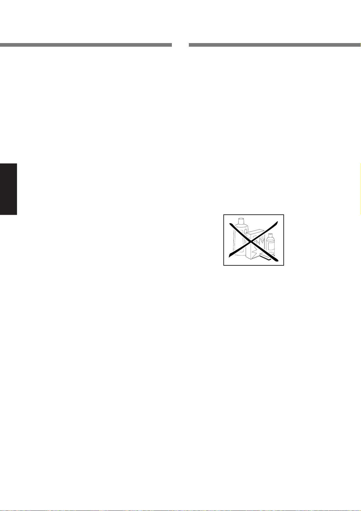
8. Fehlersuche
9. Wartung
Falls ein Fehler auftritt, ist es in vielen Fällen nicht erforderlich,
Ihren Fachhändler oder den technischen Kundendienst von
Marantz in Anspruch zu nehmen.
Überprüfen Sie die folgenden Punkte, um eine Reihe von
Problemen ohne Schwierigkeiten selbst zu beheben.
Falls sich der Fehler anhand der folgenden Überprüfung nicht
beheben lässt, wenden Sie sich bitte an Ihren Fachhändler
oder an die nächste Marantz-Kundendienststelle.
Das Gerät schaltet sich nicht ein
1. Ist das Netzkabel sicher an die Netzsteckdose
angeschlossen?
Kein Ton von den Lautsprechern
1. Wurde mit dem Eingangswahlschalter (INPUT SELECTOR) an der Gerätevorderseite die falsche
Eingangsquelle gewählt?
DEUTSCH
2. Ist der Dämpfungsschalter (ATTENUATOR) auf der
Rückseite des Gerätes auf -
3. Sind die Lautsprecherkabel richtig an die Lautsprecher
angeschlossen?
4. Ist das Anschlusskabel richtig an den Steuer-Verstärker
(Vorverstärker) angeschlossen?
5. Ist der Steuer-Verstärker (Vorverstärker) oder die
Eingangsquelle falsch eingestellt?
6. Verwenden Sie das Wiedergabegerät auf die falsche
Weise?
7. Möglicherweise hat die Schutzschaltung dieses Gerätes
angesprochen.Schalten Sie das Gerät aus, warten Sie eine
Minute oder länger, und schalten Sie das Gerät dann erneut ein.
∞ eingestellt?
■ Über die Schutzschaltung
Dieses Gerät ist mit einer Schutzschaltung ausgestattet, die die
Verstärkerschaltungen und die Lautsprecheranlage vor
Beschädigungen schützt. Falls die Schutzschaltung anspricht,
erlöschen die Messanzeigen und die Tonwiedergabe verstummt.
(Durch Drücken der Taste METER OFF erlöschen die Messanzeigen
ebenfalls.) Diese Schutzschaltung spricht in den folgenden Fällen an.
●
Beim Einschalten
Wenn das Gerät eingeschaltet wird, spricht die Schutzschaltung
an und schaltet die Tonwiedergabe etwa 8 Sekunden lang stumm,
bis sich die Verstärkerschaltung stabilisiert hat. Sobald sich die
Verstärkerschaltung stabilisiert hat, schaltet sich die
Schutzschaltung aus und die Stummschaltung der Wiedergabe
wird aufgehoben. Gleichzeitig schalten sich die Messanzeigen ein.
●
Falls ein Überstrom zur Verstärkerschaltung
fließt (Überstromschutz)
Falls ein Überstrom zur Verstärkerschaltung fließt, weil ein zu
starkes Signal eingegeben wird oder Lautsprecher mit einer
Impedanz von weniger als 4 Ω an das Gerät angeschlossen
sind, wird ein Überstrom erkannt und die Schutzschaltung
spricht an. Die Schutzschaltung spricht auch an, wenn die
Lautsprecherkabel versehentlich kurzgeschlossen sind.
Falls die Schutzschaltung anspricht, erlöschen die
Messanzeigen. Daher können Sie wissen, ob ein Problem
vorliegt oder nicht, indem Sie einfach nachsehen, ob die
Messanzeigen leuchten oder erloschen sind.
Falls die Schutzschaltung angesprochen hat, schalten Sie das
Gerät aus, warten Sie eine Minute oder länger, und schalten
Sie das Gerät dann erneut ein.
●
Falls sich der Verstärker überhitzt
In den folgenden Fällen kann sich der Verstärker überhitzen
und die Schutzschaltung spricht an.
• Falls die Entlüftungsöffnungen blockiert oder verdeckt
sind
• Falls Lautsprecher mit einer Impedanz von weniger als 4
Ω verwendet werden
• Falls das Gerät über lange Zeit bei hohem Signalausgang
verwendet wird
14
Dieser Abschnitt befasst sich mit den Pflege- und
Wartungsarbeiten, die notwendig sind, um die optimale
Leistung Ihres Marantz-Gerätes aufrechtzuerhalten.
●
Reinigen der aussenflächen des gerätes
Bei richtiger Pflege und Reinigung behält Ihr Gerät sein
Aussehen praktisch unbegrenzt. Verwenden Sie niemals
Scheuerlappen, Stahlwolle, Scheuermittel oder scharfe
Chemikalien (wie z.B. Laugen), Alkohol, Verdünner, Benzol,
Insektizide oder andere flüchtige Substanzen, weil diese die
Oberfläche des Gerätes beschädigen. Verwenden Sie auch
niemals chemisch behandelte Tücher. Falls das Gerät
schmutzig wird, wischen Sie die Außenflächen mit einem
weichen, flusenfreien Tuch ab.
Bei starker Verschmutzung:
• Etwas Spülmittel im Verhältnis 1:6 mit Wasser verdünnen.
• Ein weiches, flusenfreies Tuch in die Lösung tauchen und
gut auswringen.
• Das Gerät mit dem feuchten Tuch abwischen.
• Das Gerät mit einem trockenen Tuch trockenwischen.
●
Reparaturen
Die Wartung des Gerätes darf nur von sachkundigen und
qualifizierten Wartungstechnikern ausgeführt werden. Das von
Marantz ausgebildete Kundendienstpersonal besitzt die
Kenntnisse und die speziellen Einrichtungen, die für die
Reparatur und Kalibrierung dieses Präzisionsgerätes
erforderlich sind. Nach Ablauf der Garantiezeit werden
Reparaturen gegen eine Gebühr ausgeführt, wenn das Gerät
wieder in seinen normalen Betriebszustand zurückversetzt
werden kann.
Wenden Sie sich bei Problemen an Ihren Händler, oder
schreiben Sie direkt an die nächste Kundendienststelle, die
in der Liste der autorisierten Marantz-Vertretungen aufgeführt
ist. Bitte geben Sie bei schriftlichen Anfragen die Modell- und
Seriennummer des Gerätes zusammen mit einer möglichst
ausführlichen Beschreibung der Störung an.
Page 47

www.marantz.com
You can find your nearest authorized distributor or dealer on our website.
JAPAN Marantz Japan, Inc. 35-1 Sagami Ohno 7-Chome, Sagamihara-shi, Kanagawa 228-8505, Japan
U.S.A. Marantz America, Inc. 1100 Maplewood Drive, Itasca, IL 60143, U.S.A.
EUROPE Marantz Europe B.V. P.O. Box 8744, 5605 LS Eindhoven, The Netherlands
R
is a registered trademark.
Printed in Japan 2003/10 ECMh 339J851310
 Loading...