

Page 1
Service
MA9S1 /F1N/N1G/U1G
Manual
SECTION PAGE
1. TECHNICAL SPECIFICATIONS ................................................................................. 1
2. CAUTION ....................................................................................................................1
3. ALIGNMENTS............................................................................................................. 2
4. BLOCK DIAGRAM ...................................................................................................... 4
5. WIRING DIAGRAM ..................................................................................................... 5
6. SCHEMATIC DIAGRAM.............................................................................................. 7
7. PARTS LOCATION .................................................................................................... 11
8. EXPLODED VIEW AND PARTS LIST ....................................................................... 17
9. ELECTRICAL PARTS LIST....................................................................................... 20
Monaural Power Amplifi er
MA-9S1
TABLE OF CONTENTS
Please use this service manual with referring to the user guide ( D.F.U. ) without fail.
Printed on 100% Recycled Paper
Printed in Japan
MA-9S1
Part no. 339J855020
First Issue 2003.09
ecm
Page 2
MARANTZ DESIGN AND SERVICE
Using superior design and selected high grade components,
Only original
MARANTZ
parts can insure that your
MARANTZ
MARANTZ
product will continue to perform to the specifi cations for which
company has created the ultimate in stereo sound.
it is famous.
Parts for your
MARANTZ
ORDERING PARTS :
equipment are generally available to our National Marantz Subsidiary or Agent.
Parts can be ordered either by mail or by Fax.. In both cases, the correct part number has to be specifi ed.
The following information must be supplied to eliminate delays in processing your order :
1. Complete address
2. Complete part numbers and quantities required
3. Description of parts
4. Model number for which part is required
5. Way of shipment
6. Signature : any order form or Fax. must be signed, otherwise such part order will be considered as null and void.
USA
MARANTZ AMERICA, INC
1100 MAPLEWOOD DRIVE
ITASCA, IL. 60143
USA
PHONE : 630 - 741 - 0300
FAX : 630 - 741 - 0301
AMERICAS
SUPERSCOPE TECHNOLOGIES, INC.
MARANTZ PROFESSIONAL PRODUCTS
2640 WHITE OAK CIRCLE, SUITE A
AURORA, ILLINOIS 60504 USA
PHONE : 630 - 820 - 4800
FAX : 630 - 820 - 8103
EUROPE / TRADING
MARANTZ EUROPE B.V.
P. O. BOX 8744, BUILDING SILVERPOINT
BEEMDSTRAAT 11, 5653 MA EINDHOVEN
THE NETHERLANDS
PHONE : +31 - 40 - 2507844
FAX : +31 - 40 - 2507860
AUSTRALIA
TECHNICAL AUDIO GROUP PTY, LTD
43-53 Bridge Rd.,
STANMORE NSW 2048
AUSTRALIA
PHONE : +61 - (0)2 - 9519 - 0900
FAX : +61 - (0)2 - 9519 - 0600
CANADA
LENBROOK INDUSTRIES LIMITED
633 GRANITE COURT,
PICKERING, ONTARIO L1W 3K1
CANADA
PHONE : 905 - 831 - 6333
FAX : 905 - 831 - 6936
HONG KONG
Jolly ProAudio Broadcast Engineering Ltd.
UNIT 2, 10F, WAH HUNG CENTRE,
41 HUNG TO ROAD, KWUN TONG, KLN.,
HONG KONG
PHONE : 852 - 21913660
FAX : 852 - 21913990
AUSTRALIA
QualiFi Pty Ltd,
24 LIONEL ROAD,
MT. WAVERLEY VIC 3149
AUSTRALIA
PHONE : +61 - (0)3 - 9543 - 1522
FAX : +61 - (0)3 - 9543 - 3677
NEW ZEALAND
WILDASH AUDIO SYSTEMS NZ
14 MALVERN ROAD MT ALBERT
AUCKLAND NEW ZEALAND
PHONE : +64 - 9 - 8451958
FAX : +64 - 9 - 8463554
JAPAN
MARANTZ JAPAN, INC.
35- 1, 7- CHOME, SAGAMIONO
SAGAMIHARA - SHI, KANAGAWA
JAPAN 228-8505
PHONE : +81 42 748 1013
FAX : +81 42 741 9190
Technical
THAILAND
MRZ STANDARD CO., LTD
746 - 754 MAHACHAI ROAD.,
WANGBURAPAPIROM, PHRANAKORN,
BANGKOK, 10200 THAILAND
PHONE : +66 - 2 - 222 9181
FAX : +66 - 2 - 224 6795
TAIWAN
PAI- YUING CO., LTD.
6 TH FL NO, 148 SUNG KIANG ROAD,
TAIPEI, 10429, TAIWAN R.O.C.
PHONE : +886 - 2 - 25221304
FAX : +886 - 2 - 25630415
SHOCK, FIRE HAZARD SERVICE TEST :
SINGAPORE
WO KEE HONG DISTRIBUTION PTE LTD
130 JOO SENG ROAD
#03-02 OLIVINE BUILDING
SINGAPORE 368357
PHONE : +65 6858 5535 / +65 6381 8621
FAX : +65 6858 6078
MALAYSIA
WO KEE HONG ELECTRONICS SDN. BHD.
2ND FLOOR BANGUNAN INFINITE CENTRE
LOT 1, JALAN 13/6, 46200 PETALING JAYA
SELANGOR DARUL EHSAN, MALAYSIA
PHONE : +60 - 3 - 7954 8088
FAX : +60 - 3 - 7954 7088
KOREA
MK ENTERPRISES LTD.
ROOM 604/605, ELECTRO-OFFICETEL, 16-58,
3GA, HANGANG-RO, YONGSAN-KU, SEOUL
KOREA
PHONE : +822 - 3232 - 155
FAX : +822 - 3232 - 154
CAUTION : After servicing this appliance and prior to returning to customer, measure the resistance between either primary AC
cord connector pins ( with unit NOT connected to AC mains and its Power switch ON ), and the face or Front Panel of product and
controls and chassis bottom.
Any resistance measurement less than 1 Megohms should cause unit to be repaired or corrected before AC power is applied, and
verifi ed before it is return to the user/customer.
Ref. UL Standard No. 1492.
In case of diffi culties, do not hesitate to contact the Technical
Department at above mentioned address.
030307MIT
Page 3
1. TECHNICAL SPECIFICATIONS
Rated power output (20 Hz to 20 kHz) ................... 300 W (8 Ω load)
600 W (4 Ω load)
Total harmonic distortion ........................................................ 0.01 %
(20 Hz to 20 kHz, 8 Ω load)
Output bandwidth .......................................................5 Hz to 50 kHz
(8 Ω load, 0.05 %)
Frequency response................................................. 3 Hz to 120 kHz
(+0 / -3 dB)
Damping factor ............................................................................ 200
(20 Hz to 20 kHz, 8 Ω load)
Inout sensitivity / Inout impedance ........1.7 V / 20 kΩ (BALANCED)
1.7 V / 20 kΩ (UNBALANCED)
S/N (IHF A network, input shorted) ................. 120 dB (BALANCED)
120 dB (UNBALANCED)
Level of voltage amplifi cation............................. 29 dB (BALANCED)
29 dB (UNBALANCED)
Attenuation .....................................................0, -3, -6, -9, -12, ∞ dB
Supply voltage [/F]............................................ 100 V AC, 50 / 60 Hz
[/N] .................................................. 230 V AC, 50 Hz
[/U] .................................................. 120 V AC, 60 Hz
Power consumption [/F]........................................................... 450 W
1200 W (4 Ω, 600 W driven)
[/N]........................................................... 500 W
1200 W (4 Ω, 600 W driven)
[/U] ............................................................ 5.8 A
13 A (4 Ω, 600 W driven)
Dimensions
Width ................................................................................ 459 mm
Height ............................................................................... 198 mm
Depth................................................................................ 451 mm
Weight ................................................................................... 35.8 kg
Caution : (The layout of this amplifi er is well concerned for sound quality.)
1. When screws and washers are removed, those parts must be set to the same places.
2. When wires are removed, the wires must be installed in the same roots, same places.
3. Do not hold the side panel (001D, 002D) and the bracket (915G) to move the unit when the unit is disassembled.
1
Page 4
3. ALIGNMENTS
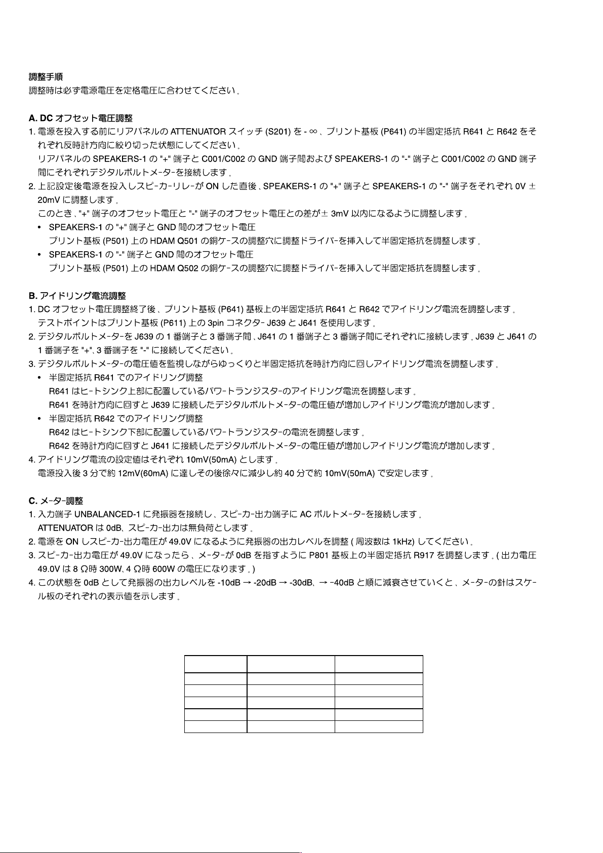
METER 8 OHM LOAD 4 OHM LOAD
0 dB 300 W 600 W
-10 dB 30 W 60 W
-20 dB 3 W 6 W
-30 dB 0.3 W 0.6 W
-40 dB 0.03 W 0.06 W
2
Page 5
Adjustment Procedure
Set the power voltage to rated voltage for this adjustment
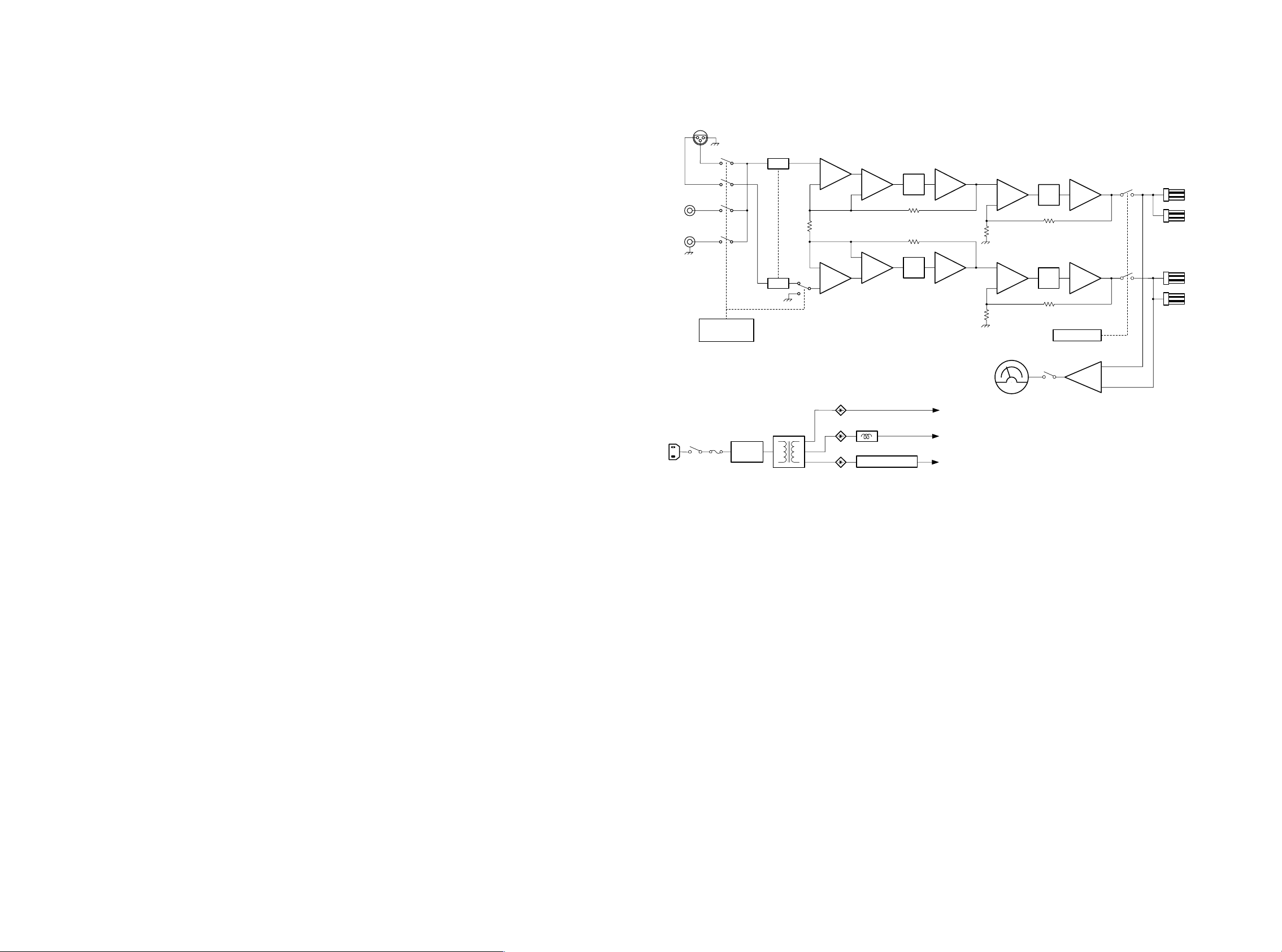
4. BLOCK DIAGRAM
DC Offset Voltage Adjustment
1. Before turning on power, set the attenuator switch(S201) at –∞, and turn the variable resisters R641
and R642 on the PCB(P641) counterclockwise to the end.
Insert digital voltage meters between the SPEAKERS–1 "+" terminal on the rear panel and the GND
terminal of C001/C002, and between the SPEAKERS–1 "–" terminal on the rear panel and the GND
terminal of C001/C002.
2. After the all preparation in Step 1 is done, turn on power. Just after the speaker relays turning on, make
the adjustment to set the offset voltages of the SPEAKERS–1 "+" terminal and the SPEAKERS–1 "–"
terminal to 0V ± 20mV.
Also, the difference between the offset voltages of the SPEAKERS–1 "+" terminal and the SPEAKERS
–1 "–" terminal must be within ±3mV.
• Offset voltage between the SPEAKERS–1 "+" terminal and GND
Insert an adjustment screw driver to the adjustment hole on the cupper cover of the HDAM Q501 on
the PCB P501 and adjust.
• Offset voltage between the SPEAKERS–1 "–" terminal and GND
Insert an adjustment screw driver to the adjustment hole on the cupper cover of the HDAM Q502 on
the PCB P501 and adjust.
Idling Current Adjustment
1. After DC Offset Voltage Adjustment is completed, adjust the idling current with the variable resisters
R641 and R642 on the PCB(P641).
2. Connect a digital voltage meter in between the 1 pin and the 3 pin of J639 and in between the 1 pin
and the 3 pin of J641 each. Connect the 1 pin terminals of J639 and J641 to "+" and the 3 pin to "–".
3. With seeing the digital voltage meter, turn the variable resisters clockwise slowly to adjust the idling
current.
• Idling current adjustment with R641
R641 is to adjust the idling current for the power transistor(s) on the upper side of the heat sink.
Turn R641 clockwise to increase the idling current. The voltage measured by the digital voltage
meter connected to J639 will increase.
• Idling current adjustment with R642
R642 is to adjust the idling current for the power transistor(s) on the lower side of the heat sink.
Turn R642 clockwise to increase the idling current. The voltage measured by the digital voltage
meter connected to J641 will increase.
4. The voltage of the idling current will be 10mV(50mA) for each.
The voltage reaches approx. 12mV(60mA) 3 minutes after turning on power then the voltage decreases
slowly to approx. 10mV(50mA) about 40 minutes after and becomes stable.
UNBALANCED
INPUT
1
BALANCED
2
12
3
INPUT
SELECTOR
SOFT
START
ATT
ATT
REGULATOR
I/V
I/V
SPEAKER
OUTPUT
I/V
I/V
PROTECT
FINAL STAGE
INPUT / DRIVE STAGE
METER / PROTECT
Meter Adjustment
1. Connect an oscillator to the input terminal UNBALANCED-1 and connect an AC voltage meter to the
speaker output terminals. ATTENUATOR is set to 0dB and no load is connected to the speaker output.
2. Turn on power and adjust output power (output frequency 1kHz) of the oscillator to set the speaker output
voltage to 49.0V.
3. When the speaker output voltage becomes 49.0V, adjust the variable resistor R917 on the PCB P801
to set the meter 0dB. (Output voltage 49.0V means 300W for 8Ω, 600W for 4Ω.)
4. Assuming this point as 0db, decrease the output power of the oscillator like –10dB ➔ –20dB ➔ –30dB
➔ –40dB, the meter will show the corresponding measurements.
3 4
Page 6
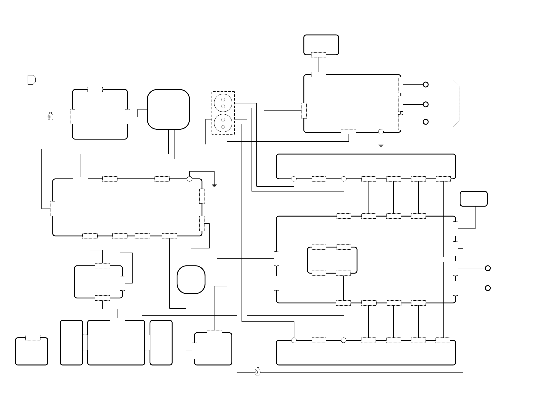
5. WIRING DIAGRAM
P201
INPUT ATT SW
J206(5P)
W014
AC IN
L004
J801(3P)
W003
J852(2P)
J803(4P)
J851(2P)
P851
AC INPUT
(SOFT START)
J804(3P)
POWER SUPPLY
(& METER DRIVE)
P801
J854(2P)
W033
L001
POWER
TRANS
J802(3P)
J822(1P)
J809(5P)
W032
W006
C001
C002
W015
W010
W029(RED)
J623(1P)
W031(BLU)
J204(5P)
J502(7P)
J609(3P)
INPUT AMP
(VOLTAGE AMP.)
J625(1P)
W019
J607(2P)
J201(3P)
P501
J202(2P)
J205(4P)
J208(1P)
J203(2P)
P611
H POWER TR (POWER DRIVER)
J613(4P) J615(3P)
W021 W023 W025
J611(4P)
J619(3P)
J007
W013
W012
W011
J617(3P) J643(3P)
J621(3P)
BALANCED
J006
UN BAL 1
J005
UN BAL 1
INPUT
P991
POSISTER
W002
J871(2P)
P871
POWER SW
J902(4P)
LEVEL ON/OFF SW
(METER SW)
P971
L LED
J971(5P)
J904(2P)
W008
J951(4P)
P951
J952(5P)
W009
J961(5P)
P961
LEVELE METER
(& LED)
W035
J953(2P)
J901(7P)
W007
P981
R LED
J981(5P)
J903(2P)
W004
L002
CHOKE
COIL
J402(2P)
J808(4P)
J401(4P)
P221
MODE SEL
(INPUT SEL)
W028(RED)
L003
J602(5P)
J601(7P)
W030(BLU)
J624(1P)
J605(3P)
IDLING ADJ
J606(3P)
W018
P641
W017
J603(2P)
P601
MAIN AMP
(POWER BUFFER AMP.)
J604(2P)
W016
J612(4P) J608(2P)
J614(4P) J616(3P) J618(3P) J610(3P)
J626(1P)
J620(3P)
P621
N POWER TR (POWER DRIVER)
J620(3P)
W024 W022 W020
W034
J640(3P)
W991
J906(2P)
J905(7P)
J635(3P)
J636(3P)
W007
W026
W027
J008
J009
SPK 1
J010
J011
SPK 2
65
Page 7

6. SCHEMATIC DIAGRAM
P501
INPUT AMP
J005
1
2
2
UNBALANCED
J006
1
1
2
BALANCED
J007
3
12.1K12.1K 10K8.25K 4.64K10K 4.64K8.25K10K 10K
R216R215
1
2
3
4
5
6
R208
7
8
9
10
R211 R213R207 R214R212R209 R210
11
12
(APA)
P201
INPUT
ATT SW
W011
W012
21
w013
J206
1
2
3
4
5
13
S201
-1
14
S201
-2
J203
1
1
2
2
(N.C.)
100k
R203
J202
1
1
2
2
100k
R202
C207
0.1
J208
J201
1
1
2
2
3
3
(N.C.)
100k
R201
W014
J204
1
1
1
2
2
2
3
3
3
4
4
4
5
5
5
C203
(N.C.)
C202
C201
(APA)
8
L204
5
8
L203
5
8
L202
5
8
L201
5
91012
-
+
1
43
91012
-
+
1
43
910 12
-
+
1
43
910 12
-
+
1
43
J205
W010
FROM J401
D201D202D203
1SS1761SS1761SS176
UNBAL-1
-24V
UNBAL-2
1234
1234
H POWER TR
P611 (AMA)
Q625
2SC2922 2SC2922 2SC2922
123123123
P641 (AMA)
-1.2
12 123
J604
W016 W018
J627
J601J502
1
1
+55V
2
2
-55V
3
3
H
4
4
GND
5
5
C
6
6
-55V
7
7
+55V
J642
J628
R603
(JUMPER)
R601
100K
R602
100K
R604
(JUMPER)
C601C602
C611
C612
C610
HLMF-K200
R541
220p
10
10
220p
R542
HLMF-K200
4
4
2
HDAM-SA
6
6
HDAM-SA
2
R535
54.5
470
Q517
1
R543
0.0
3
46.4
5
R537
-54.5
470
W015
1
1
+55V
2
2
-55V
3
3
H
4
4
GND
5
5
C
6
6
-55V
7
7
R538
470
5
3
0.0
1
Q518
R536
470
+55V
-54.5
R544
46.4
54.5
R521
20.0
2.2K 2W
C505
D501
220/25v
Q501
R503
0.0
226
0.1
220p220p
100k
R501
C501
C507
D503
220/50v
-20.0
C503
R512
(JUMPER)
R511
C504
-20.0
C508
220/25v
R206
4.7K
BAL
R204
6.8K
R205
6.8K
R502
C502
100k
0.1
R504
0.0
226
D502
C506
220/25v
20.0
C511
220/50v
HZ20-1L
Q503
3
1
4
HDAM
2
5
6
C509
220P
R523
2.2K 2W
R505
R507
3.3M
3.3M
0.1
1k
0.1
R508
R506
3.3M
3.3M
R524
2.2K 2w
D504
HZ20-1L
C510
220P
Q502
6
5
2
HDAM
1
4
0.1
3
HZ20-1L HZ20-1L
R522
2.2K 2W
2
R519
4
0.1
46.4
HDAM-SA
3
0.1
0.0
6
-40.8
C513
220/50v
-42.0
R509
3.3M
R510
3.3M
C514
R520
C512
R515
R513
3.32K
3.32K
R514
R516
3.32K
3.32K
-42.0
220/50v
-40.8
Q504
6
3
0.0
HDAM-SA
4
0.1
46.4
2
220/50v
43.3
681
R525
42.0
40.8
D505
MSS81
1
40.2
-40.2
5
D507
R527
R528
D508
5
-40.2
40.2
1
D506
40.8
42.0
R526
332
R529
Q505
2SA1349
5
42.0
27316
3
41.4
2
Q509
2SA970
Q513
2SA1145
D509
HSS81
D511
HSS81
Q515
2SC2705
MSS81
Q511
2SC2240
2
-41.4
1367
5
Q507
2SC3381
681
R517
1K
R545 R546 J503
100 1M
R518
1K
681
Q508
3
2SC3381
-41.4
Q512
2SC2240
2
Q516
HSS81
2SC2705
D512
HSS81
D510
HSS81
Q514
2SA1145
HSS81
Q510
2SA970
2
67512
Q506
2SA1349
681
D513
1
40.8
3
2
40.2
1
47k
R533
(JUMPER)
0.0
1
2
-40.2
C515
3
-40.8
1
R539
3
2
D515
-42.0
HLMF-K200
332
R531
-43.3
-43.3
332
R532
-42.0
D516
67521
HLMF-K200
3
R540
1
-40.8
3
2
-40.2
C516
1
0.0
(JUMPER)
1
47K
R534
40.2
2
3
40.8
1
3
41.3
D514
3
42.0
332
R530
43.3
IDLING ADJ
BIAS ADJ BIAS ADJ
R642 R641
2.2k 2.2k
D616
1.8 1.2
C609
470/63v
0.0
0.0
(N.C)(N.C)
470/63v
R607
R605 R609 R611
R608 R606
470/63v
R610
R612
470/63v
J606
Q601
220
220
220 220
220
220 220
220
0.0
0.0
TO J610 TO J608
4
3
Q602
3
4
R638
123
2
HDAM-SA
6
220220220
R613R615R617
220
R619
220 220 220220
R616 R618 R620R614
6
HDAM-SA
2
2.2K
R640
4.7K
-1.2
-0.6
12
J603
1212
J629
680
R621
Q603
2SA1349
53.0
67521
51.8
Q607
2SA970
Q611
2SA1360
D601
HSS81
D605
HSS81
1
51.2
-51.2
5
D607
HSS81
Q613
2SC3423
D603
HSS81
Q609
2SC2240
-51.8
Q605
5
-53.0
2SC3381
680
R623
680
R624
Q606
-53.0
2SC3381
3
2
1
-51.8
Q610
2SC2240
Q614
2SC3423
D604
HSS81
D608
HSS81
5
-51.2
51.2
1
D606
HSS81
Q612
2SA1360
D602
HSS81
Q608
2SA970
51.8
21
3
Q604
53.0
2SA1349
680
R622
2.2K
R639
D615
HSS81HSS81
4.7K
R637
1.8
1.2
-0.6
123
J605
123
W017
330
2
R629
2
-53.0
330
330
2
R630
22/25V
2
330
FROM J604
D609
68k
D611
D612
68k
D610
HLMF-K200
51.2
D613
-51.2
HLMF-K200
HLMF-K200
-51.2
D614
51.2
HLMF-K200
J607
R635
C605
(N.C)
(N.C)
C606
R636
J608
W016
54.6
R625
3
53.0
52.4
3
2
1
51.8
3
1
1.8
C603
22/25v
-1.8
1
3
-51.8
1
2
3
-52.4
21367
R627
-54.6
-54.6
R628
5
-53.0
67
-52.4
3
2
1
-51.8
3
1
-1.8
C604
1.8
1
3
51.8
1
2
3
52.4
6
7
5
53.0
R626
54.6
J630
2SD1508
132
1.2
J609
W019
12 1234
R681
22
1.8
R643
2
68
10
226K
226K
226K
226K
12
12
(N.C)(N.C) (N.C)(N.C)
D621 D617D622D618 D623D619D624 D620
(N.C)(N.C) (N.C)(N.C)
R645
2
68
-1.8
R683
22
R684
22
-1.8
R646
2
68
1.8
R644
2
68
R682
22
R631
680p
R633
R634
680p
R632
10
-1.8
-0.6
123
+48V
123
TO C001
J611
C613
0.01
D625
HSS81
1
Q617
3
2SC3421
1.2
0.0
R953
1k
R647
-1.2
3
Q619
2SA1358
1
D627
-49.0
HSS81
C615
0.01
C616
0.01
D628
-49.0
1
HSS81
Q620
2SA1358
3
-1.2
1k
R648
R954
0.0
1.2
3
Q618
2SC3421
1
D626
HSS81
C614
0.01
W020
49.0
Q615
FROM J605
W018
1.2
-1.8
-0.6
132
Q616
2SD1508
49.0
1
2SC2922
Q626
Q629
0.0 0.0 0.0
10
W029
C951
C952
J612
W028
10
2SC4883
123
W021
0.47/63V
49.0
2
HSS81
22k
22K
HSS81
2
0.47/63v
123
2SC4883
0.0
3
Q621
1.2
47
R649
4321
4321
J631
49.0
6.8K
R959
2
22k
R957
1
3
0.0
D955
HSS81
22k
R979
22K
R980
D956
HSS81
0.0
3
1
22k
R958
49.0
2
6.8k
R960
49.0
J632
47
R650
1.2
Q622
0.6 0.6
10
R659
0.6
3
Q953
2SA970
1
R975
22k
22K
R961
Q951
2SC2240
Q952
2SC2240
22k
R962
R976
22k
1
Q954
2SA970
3
J602
1234 5
W006
FROM J809
234123
0.6
10
R660
0.6
0.0
123
Q630
2SC2922
+55V
1234
J625J613J623
-48V
TO C002
2
-0.7
0V
-55V
TO C002 TO C001
-48V+48V
J626J614J624J610
-0.7
123
2SC2922
0.6
R655
4.7K
D951
R955
R956
D952
4.7K
1234 12345
1234
R656
0.6
2
Q633
R663
W031
R977
1
-0.7
-55V
W030
R664
Q634
10/3w
10/3w
2
Q627
2SA1216
0.0
1231
-0.6
10
J615
W023
100k
49.0
Q957
3
2SC2240
R679
C621
0.039
R680
C622
0.039
-0.7
3
Q958
1
49.0
100k
R978
+55V
W022
J616
10
0.6
0.0
1.5k
1.5k
R951
R987
1.5K
2SC2240
R952
123
123
123
123
123
123
1.5k1.5K
R989R988
1.5K
R990
J620
1231
R653
150 1w
C607
0.01
123
ADJ-1
BIAS TP
R675
0.1
5W
R671
0.1
5W
R667 R677
0.1 0.1
5W 5W
L951
45
R668 R678
0.1 0.1
5W 5W
R672
0.1
5W
R676
0.1
5W
123
123
C608
0.01
R654
150 1w
J639
W025
J621J619
R669
0.1
5W
R673
0.1
5W
1.5k
R995
-0.7
R985
22K
R964
68K
R963
68K
231
1.5K
R996
R674
0.1
5W
R670
0.1
5W
123
123
W034
123
J640
R657
123
J617
123
123123412
123123
1.5K
1.5K
R993
R981
Q955
TA7317P
0.0
0.0
0.0
R965
47k
R967
47k
C954
47/25V
R966
100K
C953
0.01
D953
6
1.5K
1.5K
R982
R994
J622
W024
123
J618
-0.6
R658
2
0.0
3
Q628
2SA1216
10
Q623
2SA1859
-0.6
R651
MAIN AMP
P601 (AMA)
56781234 9
0.0
1.2
0.0
0.1
C955
47/25V
R969 R968
3.3K 8.2K
HSS81
R652
Q624
2SA1859
10
-0.6
1
0.0
0.0
2SA1216
31
123
-1.2
47
J641
BIAS TP
(APM)
(APR)
1.3
3.0
R970
C956
R974
47
1W
Q635
Q631
2SA1216
3
2
R661
123 123
ADJ-2
220k
2
-0.6
J633
J634
-0.6
10
R972
10k
R971
C957
R973
10
R665
-49.0
123
100K
C958
R983
R984
(N.C)
COLD
0.47/50V 68k
-30V
RELAY
+24V
33k
GND
-24V
22K
R929
C623
R685
J643
W034
J906
2
1
0.1
J905
1
HOT
2
3
4
5
6
7
22K
R930
J635
3
2
1
0.03910
3W
3
2
1
J636
TO J643
P621 (AMA)
N POWER TR
47
-1.2
-49.0
123
10
R662
-0.6
0.0
Q632
2SA1216
10
R666
-0.6
2
0.0
3
123
Q636
2SA1216
1
FROM J640
POSISTER
P991
W991
2
1
R991
PTH487
1
2
3
4
5
6
7
W007
W026
J008
3
2
SPK-1
1
J009
J010
SPK-2
3
J011
2
1
W027
FROM J901
7 8
Page 8

AC
W001
J001
12
W003
12
J851
2
1
D857
(JUMPER)
D858
(JUMPER)
TO J623/J624
C871
P871
(APS)
0.01
S871
34
L002
12
POWER
SW
12
J871
12
W002
12
21
J852
F851
J858 J857
(N.C)
F851
250V 15A FUSE
JU06
JU08
314
1
L851
13 2
11
1
G851
R857
0.47 6.8
R853
JU04
JU02
24.1
D855
(N.C)
D856
(N.C)
D853
D854
J859
22
D851
11EQS10
D852
C853
220/35v
11EQS10
(N.C)
(N.C)
C852
0.01
1
23
D861
(N.C)
1W
C854
47/35v
R851
2.2 7w
5
L852
R854
14.6 0.7
23.0
3.3k
C855
S401
3
4
P211
R852
2.2
2
5
D859
R855
4.7K
220/35V
7W
1SS176
1
6
J856 J855
C851
0.01
5
1
L853
23
C856
10/50V
D860
(N.C)
2
Q851
2SD1862
3
1
1K
R856
S401
12
11
16
13
14
15
8
7
INPUT SELECTOR
(APA)
(APS)
P851
AC
INPUT
BALANCE
UNBAL1
10
UNBAL2
9
+24V
-24V
J854
J401
J402
212
1
2
3
4
1
2
2
1
1
L001
W010
1
TO J205
2
3
4
1
2
TO GND
C001/C002
36V
0V
36V
60V
0V
60V
26V
0V
26V
J801
3
3
2
2
1
1
J802
1
1
2
2
3
3
-55.5
J810
J803
1
1
R808
1/4W
2
3
4
GND
W004
1
2
1
2
3
4
J811
J903
1
2
+24V
-24V
1 1/4W
11EQS10
11EQS10
D808D807
21DQ1021DQ10
R807
11EQS10
G804
11EQS10
D820 D819
R817
1
1/2W
G803
11EQS10
6.8 0.47
11EQS10 11EQS10
D805 D806D803 D804
21DQ10 21DQ1021DQ10 21DQ10
6.8 0.47
D809 D810
21DQ10 21DQ10
D813D811 D812
D814
11EQS10
D817 D818D815 D816
R813
4.7
MODE SEL
1234
1234
J808
R804
1 1/2W
R803
1 1/2W
55.5
Q801
2SD1415
2
3
2
3
100100
220/25v
220/25v
R811
4.7
150150
R815R816
24.0
24V24V
C807C808
D821D822
-24.0
1
R812
2
3
4.7
Q802
2SB102011EQS10 11EQS10
33.5
Q803
D
2SK246
1
G
S
R809
C803
C805
1000/50V
C804
C806
1000/50V
Q804
D
2SK246
1
G
C809
S
1/50v
R810
-33.5
22.7
-22.7
220/25v220/25v
C801
4700/80v
C802
4700/80v
R926
22
R927
22
6.8 0.47
KCH30A15
KRH30A15
G802
C908
C909
220/25v
G801
2
31
D801
D802
13
2
2W
3.3K
R805
2W
3.3K
R806
220/25v
49.0
-49.0
2W
3.3K
R801R802
2W
3.3K
8
7
2/2
0.0
Q903
NJM2114D
2.2K
R916
1K
R931
8
5
0.0
2/2
6
Q904
0.0
NJM2114D
C904
100P
5
6
R915
1K
METER ADJ
7
0.2
R913
1K
J804
22.0
0.0
10K
R914
C903
R917
22K
67
10K
5
R922
D904
2
NJM2114D
0.0
1/2
3
4
0.0
W028/W029
W032
GND
C001
C002
22000
22000
71V 71V
W033
123
123
R912
10K
D901
1SS176
D902
7
1SS176
Q902
NJM2114D
10/16V
1K
R918
21
3
Q905
R919
2SC3381
2.2K
R923
22K 680 150
1SS176
Q903
D905
1
-0.3
W030/W031
8
2/2
+
1
-0.5
R924
1SS176
D906D907
-
-22.0
Q904
NJM2114D
0.0
1SS1761SS176
6
0.0
0.0
5
R911
4
1/2
C905
100P
TO J625/626
J807
R910
10K
1K
L901
89451210
D961
SELU1E50CM-S
-23.0
C992
10/25V
-24V
+24V
R992
3.9K
1W
J961
J952
-20.0
C961
0.1
R941
2.2K
C991
10/25V
R942
-24V
+24V
54321
54321
543
54321
-24V
+24V
1W
8.2K
ON
ON
(N.C)
R991
2.2K
C971
J822
TO J602
GND
J809
1
+55V
-55V
0.0
0.0
1
NJM2114D
R909
R920
100K
R925
2
GND
3
4
-55V
+55V
5
-22.0
4
3
0.0
1/2
0.0
Q902
2
R908
10K
1K
6.8K
10/25V
R921
C906
1.7
22.6
13
D908
1.2
U831
(N.C)
0.0
3
2
HLMF-K200
D903
R928
47
1SS176
W006
4
R901
3
0.0
0.0
R905
1
10K
Q901
NJM2114D
10K
R907
22.0
7
R906
10K
Q901
NJM2114D
C907
(N.C)
68K
1/2
0.0
2
10K10K
R904R903
R902
8
5
0.0
68K
2/2
0.0
6
COLD
RELAY
METER
HOT
-30V
+24V
GND
-24V
-24V
+24V
GND
SELU1E50CM-S
-20.0
P971
(APM)
L LED
1
1
2
2
3
3
4
4
5
5
6
6
7
7
J901
J902
1
2
3
4
0.1
D971
5
4
-23.0
3
2
1
J971
TO J905
W007
J951
W008
1
1
2
3
4
1
2
2
3
METER
3
4
GND
4
(APM)
P961
LEVELE
METER
R982
3.9K6.8 0.47
C993
1W
10/25V
M902
+-
12
C994
1/50V
METER
GND
W009
2
1
P951
GND
METER
ON/OFF
METER OFF SW
S951
4
5
63
R983
1
2
J953
1
2
P981
R LED
J981
1
2
SELU1E50CM-S
3
4
-23.0
5
(APM)
LEVEL
SW
ON
1
2
OFF
(APM)
D981
-20.0
C981
0.1
R981
2.2K
(APS)
P801
(APM)
POWER SUPPLY
J904
121
2
W035
109
Page 9

7. PARTS LOCATION
HDAM (PM01)
HDAM
PM01
JM01
+
1
JM01
2
-
QM01
2SK369
BL
RM07
147
3
G
RM09
2.2K
187
1
D
2
S
QM03
2SC2240
1
23
QM02
2SK369
BL
1
3
RM03
100
P201
P871
HDAM-SA (PH01)
+B
3
JM01
DM01
RM08
147
DM05
1SS176
RM04
560
3
1
1SS176
DM02
1SS176
QM04
2SA970
2
DM03
1SS176
DM04
1SS176
QM05
2SA970
2
RM06
33K
QM06
2SC2240
2
3
1
1
3
RM05
560
+OUT
-OUT
-B
4
5
6
JM01
JM01
JM01
RM02RM01
187
1
D
3
G
2
S
2
HDAM-SA PH01
1SS176
1SS176
+
4
JH02
1SS176
1SS176
DH01
DH03
DH04
DH02
RH05
68K
QH03
2SA970
2
QH01
2SA970
2
QH02
2SC2240
2
QH04
2SC2240
2
RH01
470
3
1
3
1
1
3
1
3
RH02
470
1
2
3
3
2
1
QH05
2SC2240
RH03
22
RH04
22
QH06
2SA970
+B
+OUT
-OUT
-B
JH02
2
P211
JH02
1
JH02
3
JH02
5
P971
P981
6
JH02
P951
11 12
P641
Page 10

P501
Q517
Q815
Q505 - Q515(Odd number)
Q506 - Q516(Even number)
Q503
Q504
Q501
Q502
P851
Q851
P801
Q801 Q802
Q803 Q804
P961
Q901 Q902
Q903 Q904 Q905
P971
1413
Page 11

P601
Q955
Q957 Q951 Q953
Q958 Q952 Q954
Q617
Q618
Q619
Q620
Q603 - Q613(Odd number)
Q604 - Q614(Even number)
Q601
Q602
P611
P621
Q625 Q629 Q663 Q621 Q615 Q623 Q627 Q631
Q636 Q632 Q628 Q624 Q616 Q622 Q634 Q630 Q626
Q635
15 16
Page 12

8. EXPLODED VIEW AND PARTS LIST
001D
5128
3X6( U)
x6
017D
5128
3X4( U)
3X8( M)
( 007B)
x6
010D
5128
3X4( U)
x2
5128
3X8( M)
037B
019B
046Bx2
( 008B)
x2
5128
3X4( U)
x2
011B
5110
3X10( U)
x4
052Bx2
928Gx4
053Bx2
041Bx2
(003B)
043B
021B
003D
008D
5128
3X8( M)
5128
3X8( M)
x2
5150
3X6( M)
x6
x4
( 5128)
x6
(006B)
013D
007D
005D
020Dx2
5128
3X6( U)
x6
5126
3X10( M)
x6
019Dx2
P211
5128
3X6( M)
x2
009B
( 002B)
003D
915Gx2
5104
3X6( M)
x2
017B
050Bx2
033Bx2
5128
3X4( U)
x2
013B
( 004B)
015B
P871
5128
3X4( U)
x2
029B
049B
028B
5128
3X6( M)
5129
3X8( M)
5405
3( M)
x7
005D
002D
026B
5110
3X6( M)
x2
024B
5104
3X6( M)
x2
5128
3X4( U)
x7
5204
4X8( M)
x5
5126
3X8( M)
x2
005G
027Gx 5
P971
5128
3X4( U)
x4
030Bx2
P961
032Bx2
5311
3( M)
x2
051Bx2
5128
3X4( U)
x2
P951
022B
5129
3X8( B)
x4
5128
3X8( M)
x2
039B
001B
FRONT PANEL ASSY.
5129
3X6( M)
047B
048B
L001
x2
5110
3X6( M)
P981
5405
4( M)
x4
011G
x2
5150
3X10( U)
x2
5204
4X8( M)
x4
001G
5150
3X10( U)
x7
026G
009Gx2
5128
3X6( M)
x3
015G
5110
4X6( M)
x4
5129
3X8( M)
x2
5405
4( M)
008Gx2
5405
4( M)
x4
927Gx2
902Gx4
P851
034G
923G
5405
4( M)
x4
5405
4( M)
x4
5204
4X8( M)
X1
007Gx6
921G
5110
3X6( M)
x4
5204
4X8( M)
x4
5128
4X10( M)
x4
L002
5128
4X20( M)
x4
5128
3X8( M)
x2
5110
3X6( M)
x4
P201
012G
5128
3X8( M)
x2
5204
4X8( M)
x4
P501
5405
4( M)
x4
907Gx4
5150
3X10( U)
x6
914G
912G
002L
922G
917Gx4
5110
3X6( M)
925Gx2
901G
001Lx2
H01Kx4
002Gx4
x2
5405
3( M)
5110
3X6( M)
x4
SYMBOL ST YLE
5104
5110
5126
5128
5129
5150
5204
5405
W001
013Lx4
1817
5150
3X10( M)
x4
918G
920Gx2
5110
3X6( M)
x2
5126
3X8( M)
x2
J008, J009, J010, J011
5110
3X6( M)
x4
5150
3X8( M)
x2
5129
3X8( M)
x5
010K
x2
5110
3X8( M)
x4
007L
P61 1
5104
3X12( M)
x12
5204
4X8( M)
x4
5405
4( M)
x4
016Lx2
5128
4X10( M)
x4
3( M)
803K
5110
3X8( M)
x4
802K
5405
906G
PARTS NAME
+F.H.M.SCREW
+B.H.M.SCREW
+ B. H. T AP T I TE SCRE W W/WAS HER
+ B. H. T AP T I TE SCRE W ( BTYPE)
+ B. H. T AP T ITE SCREW (W/ T. L. WASH ER)
+ F . H. T AP TI TE S CREW ( BTY PE)
+ H. H. T APT . BOLT S WITH F LA NGE (STITE)
TOOTHED L OCK WASH ERS
5148
3X6( M)
032G
031G
801K
809K
5405
3( M)
807K
810K
MARK MAT ERIAL / F INISH
( M ) STEEL / COPPER
( U ) STEEL/ BL ACK
(A)(B)
ST EE L / CHRO MATE
P64 1
x4
P621
5110
3X6( M)
x8
5110
3X8( M)
x2
5405
3( M)
x4
P60 1
5110
3X6( M)
5110
3X18( M)
011Lx12
806K
P801
x4
5110
3X6( M)
x4
004L
x8
P60 1
x24
5110
3X6( M)
x5
Page 13

POS.
NO
VERS.
COLOR
PART NO.
(FOR EUR)
DESCRIPTION
PART NO.
(MJI)
POS.
NO
VERS.
COLOR
PART NO.
(FOR EUR)
DESCRIPTION
PART NO.
(MJI)
001B 339J248510 FRONT PANEL ASSY 339J248510
002B 339J248110 FRONT PANEL 339J248110
003B 339J063110 ESCUTCHEON LEFT 339J063110
004B 339J063120 ESCUTCHEON RIGHT 339J063120
006B 339J353110 RING FOR METER 339J353110
007B 339J158010 WINDOW FOR METER 339J158010
008B 339J353120 RING FOR POWER SWITCH 339J353120
009B 339J265010 INDICATOR FOR METER FRONT 339J265010
011B 339J259010 BUSH FOR POWER SWITCH 339J259010
013B 339J259020 BUSH FOR METER SWITCH 339J259020
017B 339J270110 BUTTON FOR POWER SWITCH 339J270110
021B 339J154110 KNOB FOR SELECTOR SWITCH 339J154110
024B 339J270120 BUTTON FOR METER SWITCH 339J270120
027B 53110303M0 HEXAGON NUT FOR METER 53110303M0
028B 339J265020 INDICATOR FOR METER 339J265020
029B 339J355020 LENS FOR STAR MARK 339J355020
033B 339J355010 LENS FOR SIDE LIGHTING 339J355010
043B 313J251110 BADGE MARANTZ BADGE (GOLD) 313J251110
048B 340J152010 TUBE FOR LED(STAR MARK) 340J152010
049B 339J251010 BADGE FOR STAR MARK 339J251010
001D 339J249110 SIDE PANEL SIDE PANEL LEFT 339J249110
002D 339J249120 SIDE PANEL SIDE PANEL RIGHT 339J249120
007D 339J257110 LID TOP LID 339J257110
008D 339J063130 ESCUTCHEON FOR TOP LID 339J063130
010D 339J202010 NET FOR ESCUTCHEON 339J202010
002G 163J057220 LEG CUPPER 163J057220
026G 339J123010 CONTACTOR FOR CHEMICON 339J123010
914G 426T154010 KNOB FOR ATT SWITCH 426T154010
918G 339J053010 COVER FOR SPEAKER TERMINAL 339J053010
920G 339J259030 BUSHING FOR CINCH TERMINAL 339J259030
C001 OB22907110 ELECT. 22000µF 71V KG(M) OB22907110
C002 OB22907110 ELECT. 22000µF 71V KG(M) OB22907110
J001 YJ04002550 JACK AC INLET TYPE HF-301 YJ04002550
J005 YT02011300 TERMINAL EW-2560T-LH-B YT02011300
J006 YT02011300 TERMINAL EW-2560T-LH-B YT02011300
J007 YJ01004760 JACK NC3FDL-B-1 YJ01004760
J008 YT01010360 TERMINAL WBT-0765 POLE RED YT01010360
J009 YT01010370 TERMINAL WBT-0765 POLE WHT YT01010370
J010 YT01010360 TERMINAL WBT-0765 POLE RED YT01010360
J011 YT01010370 TERMINAL WBT-0765 POLE WHT YT01010370
L001 /F nsp MAINS TRANSF. SUPER LING TS45001010
L001 /N TS45001020 MAINS TRANSF. TS45001020
L001 /U nsp MAINS TRANSF. TS45001030
L002 FN21010030 CHOKE COIL 0.18H FN21010030
L003 FC50160030 FERRITE CORE TFCK-16-8-13 FC50160030
L004 FC50160030 FERRITE CORE TFCK-16-8-13 FC50160030
L005 FC50160030 FERRITE CORE TFCK-16-8-13 FC50160030
PACKING
001T /F nsp USER GUIDE MA-9S1 Japan 339J851110
001T /N/U 339J851310 USER GUIDE MA-9S1 339J851310
W001 /F nsp MAINS CORD FOR F OFC 2P ZC01803130
W001 /N ZC01803080 MAINS CORD 10A 250V
ZC01803080
2P CLASS2
W001 /U nsp MAINS CORD 13A 125V UL/CSA ZC01802100
NOT STANDARD
SPEAR PARTS
001S nsp PACKING CASE 339J801010
002S /N/U nsp PACKING CASE
339J805010
MASTER CARTON
003S nsp CUSHION F 339J809070
004S nsp CUSHION R 339J809080
NOTE : "nsp" PART IS LISTED FOR REFERENCE ONLY, MARANTZ WILL NOT SUPPLY THESE PARTS.
19
Page 14

9. ELECTRICAL PARTS LIST
ASSIGNMENT OF COMMON PARTS CODES.
RESISTORS
R : 1) GD05 × × × 140, Carbon film fixed resistor, ±5% 1/4W
R : 2) GD05 × × × 160, Carbon film fixed resistor, ±5% 1/6W
Examples ;
Resistance value
➀
0.1 Ω.... 001 10 Ω .... 100 1 kΩ .... 102 100 kΩ .... 104
0.5 Ω.... 005 18 Ω .... 180 2.7 kΩ ....272 680 kΩ .... 684
1 Ω .... 010 100 Ω .... 101 10 kΩ .... 103 1 MΩ.... 105
6.8 Ω.... 068 390 Ω .... 391 22 kΩ .... 223 4.7 MΩ.... 475
Note : Please distinguish 1/4W from 1/6W by the shape of par ts
used actually.
CAPACITORS
C : CERAMIC CAP.
3) DD1 × × × × 370, Ceramic capacitor
Examples ;
Tolerance (Capacity deviation)
➁
±0.25 pF .... 0
Tolerance of COMMON PARTS handled here are as follows :
C : CERAMIC CAP.
Examples ;
C : 5) ELECTROLY CAP. ( ), 6) FILM CAP. ( )
Examples ;
0.5 pF 5 pF .... ±0.25 pF
12 pF 560 pF .... ±5%
Capacity value
➂
0.5 pF .... 005 3 pF .... 030 100 pF .... 101
1.5 pF .... 015 47 pF .... 470 560 pF .... 561
4) DK16 × × × 300, High dielectric constant ceramic
Capacity value
➃
100 pF .... 101 1000 pF .... 102 10000 pF ....103
470 pF .... 471 2200 pF .... 222
5) EA × × × × × × 10, Electrolytic capacitor
Capacity value
➄
0.1 µF .... 104 4.7 µF .... 475 100 µF ....107
0.33 µF .... 334 10 µF .... 106 330 µF ....337
Working voltage
➅
{
➂
{
{
➅
Resistance value
Disc type
Temp.coeff.P350 N1000, 50V
Capacity value
Tolerance
capacitor
Disc type
Temp.chara. 2B4, 50V
Capacity value
One-way lead type, Tolerance ±20%
Working voltage
Capacity value
2200 µF ....228
➀
{
➁
±0.5 pF .... 1
±5% .... 5
6 pF 10 pF .... ±0.5 pF
1 pF .... 010 10 pF .... 100 220 pF .... 221
➃
{
➄
1 µF.... 105 22 µF ....226 1100 µF ....118
6.3V .... 006 25V .... 025
10V .... 010 35V .... 035
16V .... 016 50V .... 050
NOTE ON SAFETY FOR FUSIBLE RESISTOR :
The suppliers and their type numbers of fusible resistors
are as follows;
1. KOA Corporation
Part No. (MJI) Type No. (KOA) Description
NH05 × × × 140 RF25S × × × × ΩJ(±5% 1/4W)
NH05 × × × 120 RF50S × × × × ΩJ(±5% 1/2W)
NH85 × × × 110 RF73B2A × × × × ΩJ(±5% 1/10W)
NH95 × × × 140 RF73B2E × × × × ΩJ(±5% 1/4W)
2. Matsushita Electronic Components Co., Ltd
Part No. (MJI) Type No. (MEC) Description
NF05 × × × 140 ERD-2FCJ × × × (±5% 1/4W)
RF05 × × × 140
NF02 × × × 140
RF02 × × × 140
Examples ;
{
Resistance value
ERD-2FCG
{
Resistance value
Resistance value
0.1 Ω.... 001 10 Ω .... 100 1 kΩ .... 102 100 kΩ.... 104
0.5 Ω.... 005 18 Ω .... 180 2.7 kΩ ....272 680 kΩ .... 684
1 Ω .... 010 100 Ω .... 101 10 kΩ .... 103 1 MΩ.... 105
6.8 Ω.... 068 390 Ω .... 391 22 kΩ .... 223 4.7 MΩ.... 475
{
Resistance value
(0.1 Ω − 10 kΩ)
× × × (±2% 1/4W)
{
Resistance value
ABBREVIATION AND MARKS
ANT. : ANTENNA BATT. : BATTERY
CAP. : CAPACITOR CER. : CERAMIC
CONN. : CONNECTING DIG. : DIGITAL
HP : HEADPHONE MIC. : MICROPHONE
µ-PRO : MICROPROCESSOR REC. : RECORDING
RES. : RESISTOR SPK : SPEAKER
SW : SWITCH TRANSF. : TRANSFORMER
TRIM. : TRIMMING TRS. : TRANSISTOR
VAR. : VARIABLE X’TAL : CRYSTAL
NOTE ON FUSE :
Regarding to all parts of parts code FS20xxx2xx, replace
only with Wickmann-Werke GmbH, Type 372 non glass type
fuse.
6) DF15 × × × 350 Plastic film capacitor
DF15 × × × 310 One-way type, Mylar ±5% 50V
DF16 × × × 310 Plastic film capacitor
Examples ;
Capacity value
➆
0.001 µF (1000 pF) ....... 102 0.1 µF.... 104
0.0018 µF ........................ 182 0.56 µF .... 564
0.01 µF ........................ 103 1 µF .... 105
0.015 µF ........................ 153
: 1) The above CODES ( R , R , C , C and
NOTE
C ) are omitted on the schematic diagram in some
case.
2) On the occasion, be confirmed the common parts on
the parts list.
3) Refer to “Common Parts List” for the other common
parts (RI05, DD4, DK4).
➆
{
One-way type, Mylar ±10% 50V
Capacity value
NOTE ON SAFETY :
Symbol Fire or electrical shock hazard. Only original
parts should be used to replaced any part marked with
symbol . Any other component substitution (other
than original type), may increase risk of fire or electrical
shock hazard.
010728MIT
20
Page 15

POS.
NO
VERS.
COLOR
PART NO.
(FOR EUR)
DESCRIPTION
PART NO.
(MJI)
POS.
NO
VERS.
COLOR
PART NO.
(FOR EUR)
DESCRIPTION
PART NO.
(MJI)
P201-INPUT ATT
CIRCUIT BOARD
P201-RESISTORS
R207
nsp 10kΩ ±1% 1/4W GM11410020
R210
R211 nsp 8.25kΩ ±5% 1/4W GM11482510
R212 nsp 8.25kΩ ±5% 1/4W GM11482510
R213 nsp 4.64kΩ ±1% 1/4W GM11446410
R214 nsp 4.64kΩ ±1% 1/4W GM11446410
R215 nsp 12.1kΩ ±1% 1/4W GM11412120
R216 nsp 12.1kΩ ±1% 1/4W GM11412120
S201 SR02060190 ROTARY SWITCH
SR02060190
SRRM264300
P211-MODE SEL
CIRCUIT BOARD
S401 SR04030460 ROTARY SWITCH
SR04030460
SRRM435800
P501-INPUT AMP
CIRCUIT BOARD
P501-CAPACITORS
C207 nsp CER. 0.1µF +80%-20% 50V DC DD38104010
C501 OF55221590 FILM 220pF 200V OF55221590
C502 OF55221590 FILM 220pF 200V OF55221590
C503 OF55104580 FILM 0.1µF 100V OF55104580
C504 OF55104580 FILM 0.1µF 100V OF55104580
C505
nsp ELECT. 220µF M 25V ARS OA22702540
C508
C509 OF55221590 FILM 220pF ±5% 200V FAS OF55221590
C510 OF55221590 FILM 220pF ±5% 200V FAS OF55221590
C511
nsp ELECT. 220µF 50V ARS O A22705040
C514
C515 OF55221590 FILM 220pF ±5% 200V FAS OF55221590
C516 OF55221590 FILM 220pF ±5% 200V FAS OF55221590
P501-RESISTORS
R201 nsp 100kΩ ±1% 1/4W GM11410030
R202 nsp 100kΩ ±1% 1/4W GM11410030
R203 nsp 100kΩ ±1% 1/4W GM11410030
R204 nsp 6.8kΩ ±5% 1/6W GG05682160
R205 nsp 6.8kΩ ±5% 1/6W GG05682160
R206 nsp 4.7kΩ ±5% 1/6W GG05472160
R501 nsp 100kΩ ±1% 1/4W GM11410030
R502 nsp 100kΩ ±1% 1/4W GM11410030
R503 nsp 220Ω ±1% 1/4W GM11422000
R504 nsp 220Ω ±1% 1/4W GM11422000
R505
nsp 3.3MΩ ±5% 1/6W GD05335160
R510
R511 nsp 1kΩ ±1% 1/4W GM11410010
R512 nsp JUMPER nsp
R513
nsp 3.32kΩ ±1% 1/4W GM11433210
R516
R517 nsp 1kΩ ±1% 1/4W GM11410010
R518 nsp 1kΩ ±1% 1/4W GM11410010
R519 nsp 46.4Ω ±1% 1/4W GM114464G0
R520 nsp 46.4Ω ±1% 1/4W GM114464G0
R521
nsp 2.2kΩ ±5% 1W GA05222010
R524
R525
nsp 681Ω ±1% 1/4W GM11468100
R528
R529
nsp 332Ω ±1% 1/4W GM11433200
R532
R535
NF02471140 FUSE 470Ω G 1/4W NF02471140
R538
R539 nsp 10Ω ±1% 1/4W GM114100G0
R540 nsp 10Ω ±1% 1/4W GM114100G0
R541 nsp JUMPER nsp
R542 nsp JUMPER nsp
R543 nsp 46.4Ω ±1% 1/4W GM114464G0
R544 nsp 46.4Ω ±1% 1/4W GM114464G0
R545 nsp 100Ω ±1% 1/4W GM11410000
P501-RESISTORS (COMMON)
CARBON FILM FIXED RES.
±5% 1/6W : R533 R534 R546
P501-SEMICONDUCTORS
D201
nsp DIODE 1SS176 MA165 1SS254 HD 2000 2000
D203 30V 0.1A
D501
HD30020010 ZENER DIODE HZ20-1L (19V) HD3 0020010
D504
D505
nsp DIODE HSS81TD 150V 150MA HD20027010
D512
D513
HI10005340 L.E.D. HLMF-K200 #2UL RED HI10005340
D516
Q501 KH269J1010 UNIT HDAM (PM01-PCB ASSY) K H26 9J1010
Q502 KH269J1010 UNIT HDAM (PM01-PCB ASSY) K H26 9J1010
Q503 KH339J1010 UNIT HDAM-SA (PH01-PCB ASSY) KH339 J10 10
Q504 KH339J1010 UNIT HDAM-SA (PH01-PCB ASSY) KH339 J10 10
Q505 HT113492A0 TRS. 2SA1349 GR BL DUAL HT113492A0
Q506 HT113492A0 TRS. 2SA1349 GR BL DUAL HT113492A0
Q507 HT333812A0 TRS. 2SC3381 GR OR BL HT333 812A0
Q508 HT333812A0 TRS. 2SC3381 GR OR BL HT333 812A0
Q509 HT109702A0 TRS. 2SA970 GR OR BL HT109 702A 0
Q510 HT109702A0 TRS. 2SA970 GR OR BL HT109 702A 0
Q511 HT322402A0 TRS. 2SC2240 GR OR BL HT32 2402A0
Q512 HT322402A0 TRS. 2SC2240 GR OR BL HT32 2402A0
Q513 HT111452A0 TRS. 2SA1145 O OR Y HT1114 52A0
Q514 HT111452A0 TRS. 2SA1145 O OR Y HT1114 52A0
Q515 HT327052A0 TRS. 2SC2705 O OR Y H T32 7052A0
Q516 HT327052A0 TRS. 2SC2705 O OR Y H T32 7052A0
Q517 KH339J1010 UNIT HDAM-SA (PH01-PCB ASSY) KH339 J10 10
Q518 KH339J1010 UNIT HDAM-SA (PH01-PCB ASSY) KH339 J10 10
P501-MISCELLANEOUS
L201
LY20240470 RELAY ED2-24 LY 20240470
L204
P601-MAIN AMP
CIRCUIT BOARD
P601-CAPACITORS
C603 nsp ELECT. 22µF 25V ARA O A22602550
C604 nsp ELECT. 22µF 25V ARA O A22602550
C605 nsp FILM 680pF ±5% 100V FNS OF55681580
C606 nsp FILM 680pF ±5% 100V FNS OF55681580
C609
nsp ELECT.470µF 80V GOLD TUNE OA47708010
C612
C613
OF55103580 FILM 0.01µF 100V OF55103580
C616
NOTE : "nsp" PART IS LISTED FOR REFERENCE ONLY, MARANTZ WILL NOT SUPPLY THESE PARTS.
21
Page 16

POS.
NO
VERS.
COLOR
PART NO.
(FOR EUR)
DESCRIPTION
PART NO.
(MJI)
POS.
NO
VERS.
COLOR
PART NO.
(FOR EUR)
DESCRIPTION
PART NO.
(MJI)
C621 OF55393580 FILM 0.039µF 100V OF55393580
C622 OF55393580 FILM 0.039µF 100V OF55393580
C623 OF55393580 FILM 0.039µF 100V OF55393580
C951 nsp ELECT. 0.47µF M 50V RA-2 OA47 405020
C952 nsp ELECT. 0.47µF M 50V RA-2 OA47 405020
C953 nsp CER. 0.01µF +80%-20% 50V DD38103010
C954 nsp ELECT. 47µF M 25V RA-2 OA47602520
C955 nsp CER. 0.1µF +80%-20% 50V DC DD38104010
C956 nsp ELECT. 47µF M 25V RA-2 OA47602520
C957 nsp ELECT. 0.47µF M 50V RA-2 OA 4740 5020
C958 nsp CER. 0.1µF +80%-20% 50V DC DD38104010
P601-RESISTORS
R601 nsp 100kΩ ±1% 1/4W GM11410030
R602 nsp 100kΩ ±1% 1/4W GM11410030
R603 nsp JUMPER nsp
R604 nsp JUMPER nsp
R605
nsp 220Ω ±1% 1/4W GM11422000
R620
R621
nsp 680Ω ±5% 1/6W GG05681160
R624
R625
nsp 330Ω ±5% 1/6W GG05331160
R628
R631
nsp 226kΩ ±1% 1/4W GM11422630
R634
R635 nsp 10Ω ±1% 1/4W GM114100G0
R636 nsp 10Ω ±1% 1/4W GM114100G0
R643 nsp 68Ω ±5% 1/6W GG05680160
R644 nsp 68Ω ±5% 1/6W GG05680160
R645 nsp 68Ω ±5% 1/6W GG05680160
R646 nsp 68Ω ±5% 1/6W GG05680160
R647 nsp 1kΩ ±5% 1/6W GG05102160
R648 nsp 1kΩ ±5% 1/6W GG05102160
R667
GW05001050 0.1Ω J 5W BWR5 GW05001050
R678
R679 nsp 10Ω ±5% 3W GA05100030
R680 nsp 10Ω ±5% 3W GA05100030
R681 nsp 22Ω ±5% 1/6W GG05220160
R682 nsp 22Ω ±5% 1/6W GG05220160
R683 nsp 22Ω ±5% 1/6W GG05220160
R684 nsp 22Ω ±5% 1/6W GG05220160
R685 nsp 10Ω ±5% 3W GA05100030
R951 nsp 1.5kΩ ±5% 1/6W GG05152160
R952 nsp 1.5kΩ ±5% 1/6W GG05152160
R953 nsp 4.7kΩ ±5% 1/6W GG05472160
R954 nsp 4.7kΩ ±5% 1/6W GG05472160
R974 NK05470010 METAL 47Ω ±5% 1W NK05470010
R981 nsp 1.5kΩ ±5% 1/6W GG05152160
R982 nsp 1.5kΩ ±5% 1/6W GG05152160
R987
nsp 1.5kΩ ±5% 1/6W GG05152160
R990
R993
nsp 1.5kΩ ±5% 1/6W GG05152160
R996
P601-RESISTORS (COMMON)
CARBON FILM FIXED RES.
±5% 1/6W : R629 R630 R637 R637
R638-R640 R809 R810 R815 R816
R854-R856 R901-R916 R918 R919
P601-SEMICONDUCTORS
D601
nsp DIODE HSS81TD 150V 150MA HD20027010
D608
D609 HI10005340 L.E.D. HLMF-K200 RED HI 10005340
D610 HI10005340 L.E.D. HLMF-K200 RED HI 10005340
D611 HI10005340 L.E.D. HLMF-K200 RED HI 10005340
D612 HI10005340 L.E.D. HLMF-K200 RED HI 10005340
D625
nsp DIODE HSS81TD 150V 150MA HD20027010
D628
D951 nsp DIODE HSS81TD 150V 150MA HD20027010
D952 nsp DIODE HSS81TD 150V 150MA HD20027010
D953 nsp DIODE HSS81TD 150V 150MA HD20027010
D955 nsp DIODE HSS81TD 150V 150MA HD20027010
D956 nsp DIODE HSS81TD 150V 150MA HD20027010
Q601 KH339J1010 UNIT HDAM-SA (PH01-PCB ASSY) KH339 J10 10
Q602 KH339J1010 UNIT HDAM-SA (PH01-PCB ASSY) KH339 J10 10
Q603 HT113492A0 TRS. 2SA1349 GR BL DUAL H T113 492A0
Q604 HT113492A0 TRS. 2SA1349 GR BL DUAL H T113 492A0
Q605 HT333812A0 TRS. 2SC3381 GR OR BL HT333 812A0
Q606 HT333812A0 TRS. 2SC3381 GR OR BL HT333 812A0
Q607 HT109702A0 TRS. 2SA970 GR OR BL HT109 702A 0
Q608 HT109702A0 TRS. 2SA970 GR OR BL HT109 702A 0
Q609 HT322402A0 TRS. 2SC2240 GR OR BL HT32 2402A0
Q610 HT322402A0 TRS. 2SC2240 GR OR BL HT32 2402A0
Q611 HT113602A0 TRS. 2SA1360 O OR Y HT1136 02A0
Q612 HT113602A0 TRS. 2SA1360 O OR Y HT1136 02A0
Q613 HT334232A0 TRS. 2SC3423 O OR Y H T33 4232A0
Q614 HT334232A0 TRS. 2SC3423 O OR Y H T33 4232A0
Q617 HT334212A0 TRS. 2SC3421 O Y
HT334212A0
120V 1A PC=1.5W(10W)
Q618 HT334212A0 TRS. 2SC3421 O Y
HT334212A0
120V 1A PC=1.5W(10W)
Q619 HT113582A0 TRS. 2SA1358 O Y
HT113582A0
120V 1A PC=1.5W(10W)
Q620 HT113582A0 TRS. 2SA1358 O Y
HT113582A0
120V 1A PC=1.5W(10W)
Q951 HT322402A0 TRS. 2SC2240 GR OR BL HT3 22402A0
Q952 HT322402A0 TRS. 2SC2240 GR OR BL HT3 22402A0
Q953 HT109702A0 TRS. 2SA970 GR OR BL HT109 702A 0
Q954 HT109702A0 TRS. 2SA970 GR OR BL HT109 702A 0
Q955 HC10042050 IC TA7317P HC1004 2050
Q957 HT322402A0 TRS. 2SC2240 GR OR BL HT32 2402A0
Q958 HT322402A0 TRS. 2SC2240 GR OR BL HT32 2402A0
P601-MISCELLANEOU
L951 LY20240430 RELAY JC2AD-DC24V
LY20240430
(AR3422 M02)
P611-H POWER TR
CIRCUIT BOARD
P611-CAPACITOR
C607 OF55103580 FILM 0.01µF 100V O
F55103580
P611-RESISTORS
R649 nsp 47Ω ±5% 1/6W GG05470160
R651 nsp 47Ω ±5% 1/6W GG05470160
R653 nsp 150Ω ±5% 1W GA05151010
R655 nsp 10Ω ±5% 1/4W GG05100140
R657 nsp 10Ω ±5% 1/4W GG05100140
R659 nsp 10Ω ±5% 1/4W GG05100140
R661 nsp 10Ω ±5% 1/4W GG05100140
R663 nsp 10Ω ±5% 1/4W GG05100140
R665 nsp 10Ω ±5% 1/4W GG05100140
NOTE : "nsp" PART IS LISTED FOR REFERENCE ONLY, MARANTZ WILL NOT SUPPLY THESE PARTS.
22
Page 17

POS.
NO
VERS.
COLOR
PART NO.
(FOR EUR)
DESCRIPTION
PART NO.
(MJI)
POS.
NO
VERS.
COLOR
PART NO.
(FOR EUR)
DESCRIPTION
PART NO.
(MJI)
P611-SEMICONDUCTORS
Q615 HT415080A0 TRS. 2SD1508
HT415080A0
DARLINGTON HFE>4000
Q621 HT348832A0 TRS. 2SC4883 O OR Y HT348832A0
Q623 HT118592A0 TRS. 2SA1859 O OR Y HT11859 2A0
Q625/
HK121619F0 TRS. PAIR KIT
Q627
Q629/
HK121619F0 TRS. PAIR KIT
Q631
Q633/
HK121619F0 TRS. PAIR KIT
Q635
2SA1216/2SC2922 O.OR Y PAIR
2SA1216/2SC2922 O.OR Y PAIR
2SA1216/2SC2922 O.OR Y PAIR
HK121619F0
HK121619F0
HK121619F0
P621-N POWER TR
CIRCUIT BOARD
P621-CAPACITOR
C608 OF55103580 FILM 0.01µF 100V OF55103580
P621-RESISTORS
R650 nsp 47Ω ±5% 1/6W GG05470160
R652 nsp 47Ω ±5% 1/6W GG05470160
R654 nsp 150Ω ±5% 1W GA05151010
R656 nsp 10Ω ±5% 1/4W GG05100140
R658 nsp 10Ω ±5% 1/4W GG05100140
R660 nsp 10Ω ±5% 1/4W GG05100140
R662 nsp 10Ω ±5% 1/4W GG05100140
R664 nsp 10Ω ±5% 1/4W GG05100140
R666 nsp 10Ω ±5% 1/4W GG05100140
P621-SEMICONDUCTORS
Q616 HT415080A0 TRS. 2SD1508
HT415080A0
DARLINGTON HFE>4000
Q622 HT348832A0 TRS. 2SC4883 O OR Y HT348832A0
Q624 HT118592A0 TRS. 2SA1859 O OR Y HT11859 2A0
Q626/
HK121619F0 TRS. PAIR KIT
Q628
Q630/
HK121619F0 TRS. PAIR KIT
Q632
Q634/
HK121619F0 TRS. PAIR KIT
Q636
2SA1216/2SC2922 O.OR Y PAIR
2SA1216/2SC2922 O.OR Y PAIR
2SA1216/2SC2922 O.OR Y PAIR
HK121619F0
HK121619F0
HK121619F0
P641-IYDLING ADJ
CIRCUIT BOARD
D615 nsp DIODE HSS81TD 150V 150MA HD 2002 7010
D616 nsp DIODE HSS81TD 150V 150MA HD 2002 7010
R641 RA02220760 TRIM. VARIABLE 2.2kΩ VERT RA02220760
R642 RA02220760 TRIM. VARIABLE 2.2kΩ VERT RA02220760
P641-RESISTORS (COMMON)
CARBON FILM FIXED RES.
±5% 1/6W : R920-R923
P801-POWER SUPPLY
CIRCUIT BOARD
P801-CAPACITORS
C801 nsp ELECT. 4700µF 80V GOLD TUNE OA47808010
C802 nsp ELECT. 4700µF 80V GOLD TUNE OA47808010
C803 nsp ELECT. ELNA RA2 16X25 OA10 805020
C804 nsp ELECT. ELNA RA2 16X25 OA10 805020
C805 nsp ELECT. 220µF M 25V RA-2 OA22702520
C806 nsp ELECT. 220µF M 25V RA-2 OA22702520
C807 nsp ELECT. 220µF M 25V RA-2 OA22702520
C808 nsp ELECT. 220µF M 25V RA-2 OA22702520
C809 nsp ELECT. 1µF M 50V RA-2 OA10505020
C903 nsp ELECT. 10µF M 25V RA-2 OA10602520
C904 OF15101540 FILM 100pF J 100V APSV OF15101540
C905 OF15101540 FILM 100pF J 100V APSV OF15101540
C906 nsp ELECT. 10µF M 25V RA-2 OA10602520
C908 nsp ELECT. 220µF M 25V RA-2 OA22702520
C909 nsp ELECT. 220µF M 25V RA-2 OA22702520
P801-RESISTORS
R801 nsp 3.3kΩ ±5% 2W GA05332020
R802 nsp 3.3kΩ ±5% 2W GA05332020
R803 nsp 1Ω ±5% 1/2W GG05010120
R804 nsp 1Ω ±5% 1/2W GG05010120
R805 nsp 3.3kΩ ±5% 2W GA05332020
R806 nsp 3.3kΩ ±5% 2W GA05332020
R807 nsp 1Ω ±5% 1/4W GG05010140
R808 nsp 1Ω ±5% 1/4W GG05010140
R811 nsp 4.7Ω
±5% 1/6W GG05047160
R812 nsp 4.7Ω ±5% 1/6W GG05047160
R813 nsp 4.7Ω ±5% 1/6W GG05047160
R817 nsp 1Ω ±5% 1/2W GG05010120
R917 RA02230780 TRIM. 22KΩRH0638CJ4R RA02230780
R926 nsp 22Ω ±5% 1/6W GG05220160
R927 nsp 22Ω ±5% 1/6W GG05220160
R928 nsp 47Ω ±5% 1/6W GG05470160
P801-RESISTORS (COMMON)
CARBON FILM FIXED RES.
±5% 1/6W : R924 R925 R930 R941
R955-R973 R975-R978
P801-SEMICONDUCTORS
D801 HE10007100 DIODE KCH30A15 HE10007100
D802 HE10008100 DIODE KRH30A15 HE10008100
D803
nsp DIODE 21DQ10 HD20059100
D810
D811
HD20055100 DIODE SHOTTKY H D20055100
D820 11EQS10 1A 100V
D821 HD32401000 ZENER DIODE 24V HD324 01000
D822 HD32401000 ZENER DIODE 24V HD324 01000
D901 nsp DIODE 1SS176 MA165 1SS254
HD20002000
30V 0.1A
D902 nsp DIODE 1SS176 MA165 1SS254
HD20002000
30V 0.1A
D903 HI10005340 L.E.D. HLMF-K200 #2UL RED H I 10005340
D904
nsp DIODE 1SS176 MA165 1SS254 HD 2000 2000
D908 30V 0.1A
Q801 HT41415100 TRS. 2SD1415 H T41415100
Q802 HT21020100 TRS. 2SB1020 HT21020100
Q803 HF202461C0 F.E.T. 2SK246 GR HF202461C0
Q804 HF202461C0 F.E.T. 2SK246 GR HF202461C0
Q901
HC10111090 IC NJM2114D HC10 111090
Q904 DUAL LOW NOISE OP-AMP
Q905 HT333812A0 TRS. 2SC3381 GR OR BL HT3338 12A0
P801-MISCELLANEOUS
G801
BF47400020 CAP.COMP. BF 47 40 0020
G804 0.47uF+6.8Ω RFD2B474K
L901 LY20240470 RELAY ED2-24 LY20240470
P851-AC INPUT
CIRCUIT BOARD
P851-CAPACITORS
C851 nsp FILM. 0.01µF M 250V AC DF77103500
C852 nsp FILM. 0.01µF M 250V AC DF77103500
C853 nsp ELECT. 220µF 35V M RA-2 OA22703520
C854 nsp ELECT. 47µF M 35V RA-2 OA47603520
C855 nsp ELECT. 220µF 35V M RA-2 OA22703520
C856 nsp ELECT. 10µF M 50V RA-2 OA10605020
P851-RESISTORS
R851 NQ15022070 ROTOR 2.2Ω 7W
NQ15022070
W/TEMP.FUSE
NOTE : "nsp" PART IS LISTED FOR REFERENCE ONLY, MARANTZ WILL NOT SUPPLY THESE PARTS.
23
Page 18

POS.
NO
VERS.
COLOR
PART NO.
(FOR EUR)
DESCRIPTION
PART NO.
(MJI)
POS.
NO
VERS.
COLOR
PART NO.
(FOR EUR)
DESCRIPTION
PART NO.
(MJI)
R852 NQ15022070 ROTOR 2.2Ω 7W
NQ15022070
W/TEMP.FUSE
R853 nsp 22Ω ±5% 1W GA05220010
R857 nsp 1Ω ±5% 1/6W GG05010160
P851-RESISTORS (COMMON)
CARBON FILM FIXED RES.
±5% 1/6W : R979-R981
P851-SEMICONDUCTORS
D851 HD20055100 DIODE SHOTTKY
HD20055100
11EQS10 1A 100V
D852 HD20055100 DIODE SHOTTKY
HD20055100
11EQS10 1A 100V
D857 nsp JUMPER nsp
D858 nsp JUMPER nsp
D859 nsp DIODE HSS81TD 150V 150MA HD20027010
Q851 HT418622A0 TRS. 2SD1862 TV-2 NPN Q R HT418 622A 0
P851-MISCELLANEOUS
F851 /F/U nsp FUSE 250V 15A NSF GAR FS1 1500560
F851 /N FS10630850 FUSE 250V 6.3A BS LISTED FS10630850
G851 BF47400020 CAP.COMP.
BF47400020
0.47uF+6.8Ω RFD2B474K
J855 nsp JACK nsp
J856 nsp JACK nsp
L851 /F nsp POWER TRANSF. AC100V T S13 521090
L851 /N TS13521080 POWER TRANSF. AC230V T S13 52 1080
L851 /U nsp POWER TRANSF. AC120V TS13 521070
L852 LY10240240 RELAY VS24MB-NR
LY10240240
TV-8 SEMKO LISTED
L853 LY10240240 RELAY VS24MB-NR
LY10240240
TV-8 SEMKO LISTED
P871-POWER SW
CIRCUIT BOARD
C871 nsp FILM. 0.01µF M 250V AC DF 77103500
S871 SP01010830 PUSH SWITCH POWER
SP01010830
TV-8 UL.CSA SEMKO
P951-LEVEL ON/OFF SW
CIRCUIT BOARD
S951 SP02010960 PUSH SWITCH ALPS SUL S P0201 096 0
P961-LEVELE METER
CIRCUIT BOARD
C961 nsp CER. 0.1µF +80%-20% 50V DC DD38104010
C991 nsp ELECT. 10µF M 25V RA-2 OA10602520
C992 nsp ELECT. 10µF M 25V RA-2 OA10602520
C993 nsp ELECT. 10µF M 25V RA-2 OA10602520
C994 nsp ELECT. 1µF M 50V RA-2 OA10505020
D961 HI10040080 L.E.D. SELU1E10CXM-S BLUE HI 10040080
M902 IM31050010 V.U METER KFM-8A LEVEL I M3 10 50 01 0
R942 nsp 8.2kΩ ±5% 1W GA05822010
R982 nsp 3.9kΩ ±5% 1W GA05392010
R983 nsp 2.2kΩ ±5% 1/6W GD05222160
R992 nsp 3.9kΩ ±5% 1W GA05392010
P971-L LED
CIRCUIT BOARD
C971 nsp CER. 0.1µF +80%-20% 50V DC DD38104010
D971 HI10040080 L.E.D. SELU1E10CXM-S BLUE HI 10040080
R985 nsp 2.2kΩ ±5% 1/6W GD05222160
P981-R LED
CIRCUIT BOARD
C981 nsp CER. 0.1µF +80%-20% 50V DC DD38104010
D981 HI10040080 L.E.D. SELU1E10CXM-S BLUE HI 10040080
R991 nsp 2.2kΩ ±5% 1/6W GD05222160
P991-POSISTOR
CIRCUIT BOARD
R991 HP00009230 POSISTOR PTH487 (01BB-120) HP00009230
PH01-HDAM-SA
CIRCUIT BOARD
PH01-RESISTORS (COMMON)
CARBON FILM FIXED RES.
±5% 1/6W : RH01-RH05
PH01-SEMICONDUCTORS
DH01
nsp DIODE 1SS176 MA165 1SS254 HD 2000 2000
DH04 30V 0.1A
QH01 HT109702A0 TRS. 2SA970 GR OR BL H T109 702A0
QH02 HT322402A0 TRS. 2SC2240 GR OR BL HT32 2402A0
QH03 HT109702A0 TRS. 2SA970 GR OR BL H T109 702A0
QH04 HT322402A0 TRS. 2SC2240 GR OR BL HT3 224 02A0
QH05 HT322402A0 TRS. 2SC2240 GR OR BL HT3 224 02A0
QH06 HT109702A0 TRS. 2SA970 GR OR BL H T109 702A0
PM01-HDAM
CIRCUIT BOARD
PM01-RESISTORS
RM01 nsp 187Ω ±1% 1/6W GM11618700
RM02 nsp 187Ω ±1% 1/6W GM11618700
RM07 nsp 147Ω ±1% 1/6W GM11614700
RM08 nsp 147Ω ±1% 1/6W GM11614700
RM09 RA02220780 TRIM. 2.2kΩ RH0638CJ3R RA02220780
PM01-RESISTORS (COMMON)
CARBON FILM FIXED RES.
±5% 1/6W : RM03-RM06
PM01-SEMICONDUCTORS
DM01
nsp DIODE 1SS176 MA165 1SS254 HD20002000
DM05 30V 0.1A
QM01 HF203691B0 F.E.T. 2SK369 BL
HF203691B0
VGDS-40V PD0.4W
QM02 HF203691B0 F.E.T. 2SK369 BL
HF203691B0
VGDS-40V PD0.4W
QM03 HT322402A0 TRS. 2SC2240 GR OR BL H T32 2402A0
QM04 HT109702A0 TRS. 2SA970 GR OR BL HT1 0970 2A0
QM05 HT109702A0 TRS. 2SA970 GR OR BL HT1 0970 2A0
QM06 HT322402A0 TRS. 2SC2240 GR OR BL H T32 2402A0
NOTE : "nsp" PART IS LISTED FOR REFERENCE ONLY, MARANTZ WILL NOT SUPPLY THESE PARTS.
24
 Loading...