

Page 1

ACCESS PLATFORM
120 AETJ L
150 AETJ C
150 AETJ L
170 AETJ L
547378 EN (01 / 06 / 2006)
BP 249 Z. I.
44158 ANCENIS CEDEX - FRANCE
TEL : 33 (0)2 40 09 10 11
YOUR DEALER
OPERATOR’S MANUAL
THIS INSTRUCTION LEAFLET MUST BE KEPT PERMANENTLY ON THE ACCESS PLATFORM AND BE READ AND
UNDERSTOOD BY THE OPERATORS.
Page 2

PREAMBLE
This instructions manual is designed to
explain how to operate the machine and the maintenance required periodically for the machine to continue to
operate in complete safety.
The platform has been designed and produced to enable you to work at high level in complete
safety.
Before its delivery, MANITOU and the
concessionaire have carefully inspected the platform so
that you receive it in perfect operating condition.
Page 3

THE TEXTS AND ILLUSTRATIONS IN THIS DOCUMENT MUST NOT BE REPRODUCED EITHER WHOLLY OR IN PART.
1 - OPERATING AND SAFETY INSTRUCTIONS
2 - DESCRIPTION
3 - MAINTENANCE
4 - MAINTENANCE HANDBOOK
06/02/2006
01/06/2006
1ST DATE OF ISSUE
UP DATING (2-6 ; 2-7 ; 2-9 ; 3-9)
Page 4
REAR
FRONT
Page 5

1 - OPERATING
AND SAFETY
INSTRUCTIONS
1 - OPERATING
AND SAFETY
INSTRUCTIONS
1 - 1
Page 6

1 - 2
Page 7

1 - 3
TABLE OF CONTENTS
INSTRUCTIONS TO THE COMPANY MANAGER
PREAMBLE
THE OPERATOR
THE PLATFORM
A - THE PLATFORM’S SUITABILITY FOR USE
B - ADAPTING THE PLATFORM TO THE USUAL ENVIRONMENTAL CONDITIONS
C - MODIFYING THE PLATFORM
THE INSTRUCTIONS
THE MAINTENANCE
INSTRUCTIONS FOR THE OPERATOR
PREAMBLE
GENERAL INSTRUCTIONS
A - OPERATOR'S MANUAL
B - AUTHORIZATION FOR USE IN FRANCE
(or see current legislation in other countries).
C - MAINTENANCE
D - MODIFYING THE PLATFORM
E - PLATFORMAXLES
DRIVING INSTRUCTIONS
A - BEFORE STARTING THE PLATFORM
B - DRIVER’S OPERATING INSTRUCTIONS
C - ENVIRONMENT
D - VISIBILITY
E - STARTING THE PLATFORM
F - DRIVING THE PLATFORM
G - STOPPING THE PLATFORM
INSTRUCTIONS FOR WELDING AND BLOW TORCH WORK ON THE EXTERNAL STRUCTURE
A - WITH ELECTRICAL WELDING EQUIPMENT
B - WITH A BLOW TORCH
PLATFORM MAINTENANCE INSTRUCTIONS
GENERAL INSTRUCTIONS
MAINTENANCE
LUBRICANT AND FUEL LEVELS
LEVEL OF ELECTROLYTE IN THE BATTERY
HYDRAULIC
ELECTRICITY
WELDING ON THE ACCESS PLATFORM
WASHING THE PLATFORM
IF THE PLATFORM IS NOT TO BE USED FOR A LONG TIME
INTRODUCTION
PREPARING THE PLATFORM
PROTECTING THE I.C. ENGINE
CHARGING THE BATTERIES
PROTECTING THE PLATFORM
BRINGING THE PLATFORM BACK INTO SERVICE
SAFETY DECALS
1 - 4
1 - 4
1 - 4
1 - 4
1 - 4
1 - 4
1 - 5
1 - 5
1 - 5
1 - 6
1 - 6
1 - 6
1 - 6
1 - 6
1 - 7
1 - 7
1 - 7
1 - 8
1 - 8
1 - 8
1 - 8
1 - 9
1 - 10
1 - 11
1 - 12
1 - 13
1 - 13
1 - 13
1 - 14
1 - 14
1 - 14
1 - 14
1 - 14
1 - 14
1 - 15
1 - 15
1 - 15
1 - 16
1 - 16
1 - 16
1 - 16
1 - 17
1 - 17
1 - 17
1 - 18
Page 8
1 - 4
INSTRUCTIONS TO THE COMPANY MANAGER
PREAMBLE
THE OPERATOR
- Only qualified, authorized personnel can use the platform. This authorization is given in writing by the appropriate person in the establishment with respect to the use of platform and must be carried permanently by the operator.
On the basis of experience, there are a number of possible situations in which operating the platform is contra-indicated. Such
foreseeable abnormal uses, the main ones being listed below, are strictly forbidden.
- The foreseeable abnormal behaviour resulting from ordinary neglect, but does not result from any wish to put the
machinery to any improper use.
- The reflex reactions of a person in the event of a malfunction, incident, fault, etc. during operation of the platform.
- Behaviour resulting from application of the "principle of least action" when performing a task.
- For certain machines, the foreseeable behaviour of such persons as : apprentices, teenagers, handicapped persons,
trainees tempted to drive a platform, operator tempted to operate a truck to win a bet, in competition or for their own
personal experience.
The person in charge of the equipment must take these criteria into account when assessing whether or not a person will make a
suitable driver.
OBTAIN INFORMATION ON :
- How to behave when there is a fire.
- The location of the nearest first aid kit and fire extinguisher.
- The emergency telephone numbers for calling (the doctors, ambulance, hospital and fire brigade).
THE PLATFORM
A - THE PLATFORM'S SUITABILITY FOR USE
- MANITOU has ensured that this platform is suitable for use under the standard operating conditions defined in this operator's manual, with an overload test coefficient of 1,25 and an operational test coefficient of 1,1, as stipulated in standardised norm EN 280 for MPLP (Mobile Personnel Lifting Platforms).
- Before commissioning, the company manager must make sure that the platform is appropriate for the work to be done,
and perform certain tests (in accordance with current legislation).
B - ADAPTATING THE PLATFORM TO THE USUAL ENVIRONMENTAL CONDITIONS
- In addition to series equipment mounted on your platform, many options are available, such as : flashing light, working
headlight, etc.
Contact your dealer.
- Take into account climatic and atmospheric conditions of the site of utilisation.
. Protection against frost (see : 3 - MAINTENANCE : LUBRICANTS AND FUEL).
. Adaptation of lubricants (ask your dealer for information).
. I.C. engine filtration (see : 3 - MAINTENANCE : FILTERS CARTRIDGES AND BELTS).
WHENEVER YOU SEE THIS SYMBOL IT MEANS :
WARNING ! BE CAREFUL ! YOUR SAFETY OR THE SAFETY OF THE
PLATFORM IS AT RISK.
Page 9

1 - 5
For operation under average climatic conditions, i.e. : between -15 °C and + 35 °C, correct levels of lubricants in all the circuits are checked
in production. For operation under more severe climatic conditions, before starting up, it is necessary to drain all the circuits, then ensure
correct levels of lubricants using lubricants properly suited to the relevant ambient temperatures. It is the same for the cooling liquid.
- A platform operating in an area without fire extinguishing equipment must be equipped with an individual extinguisher.
There are solutions, consult your dealer.
Your platform is designed for outdoor use under normal atmospheric conditions and indoor use in suitably aerated and ventilated
premises. It is prohibited to use the platform in areas where there is a risk of fire or which are potentially explosive (e.g. Refineries,
fuel or gas depots, stores of inflammable products…). For use in these areas, specific equipment is available (ask your dealer for
information).
C - MODIFYING THE PLATFORM
- For your safety and that of others, you must not change the structure and settings of the various components used in
your platform (hydraulic pressure, calibrating limiters, I.C. engine speed, addition of extra equipment, addition of counterweight, unapproved attachments, alarm systems, etc.) yourself. In this event, the manufacturer cannot be held responsible.
THE INSTRUCTIONS
- The operator's manual must always be in good condition and kept in the place provided on the platform and in the language used by the operator.
- You must necessarily replace the instructions manual, as well as any plates or stickers, if they are no longer legible or
are missing or damaged.
THE MAINTENANCE
- Maintenance or repairs other than those detailed in part : 3 - MAINTENANCE must be carried out by qualified personnel (consult your dealer) and under the necessary safety conditions to maintain the health of the operator and any third
party.
Your patform must be inspected periodically to ensure that it remains in compliance. The frequency of this inspection is
defined by current legislation in the country in which the platform is used.
Page 10
1 - 6
INSTRUCTIONS FOR THE OPERATOR
PREAMBLE
The risk of accident while using, servicing or repairing your platform can be restricted if you follow the safety instructions and safety
measures detailed in these instruction.
- Only the operations and manœuvres described in these operator's manual must be performed. The manufacturer cannot predict all possible risky situations. Consequently, the safety instructions given in the operator's manual and on the
platform itself are not exhaustive.
- At any time, as an operator, you must envisage, within reason, the possible risk to yourself, to others or to the platform
itself when you use it.
Failure to respect the safety and operating instructions, or the instructions for repairing or servicing your platform may lead to serious,
even fatal accident.
GENERAL INSTRUCTIONS
A - OPERATOR’S MANUAL
- Carefully read and understand the operator's manual.
- The operator’s manual must always be kept in the place provided for it on the platform and be written in the language
used by the operator.
- Any operations or manoeuvres not described in the operator’s manual must necessarily be forbidden right from the
start.
- Follow the safety advice and the instructions on the platform.
- Ypu must necessarily replace the operator’s manual, as well as any plates or stickers, if they are no longer legible or
are damaged.
- A second operator must necessaily be present on the ground as a safety measure when using the platform.
- Familiarise yourself with the platform on the terrain it has to travel over.
- The machine must also be used in accordance with good engineering practice.
- Do not use the platform if the wind speed is over 45 km/h. The platform’s arms must not be subjected to a lateral force
of more than 40 kg (platforms for indoor use must not be used outside the building).
B - AUTHORIZATION FOR USE IN FRANCE
(or see current legislation in other countries)
- Only qualified, authorized personnel may use the platform. This authorization is given in writing by the appropriate
person in the company, in charge of using the platform, and must be permanently carried by the operator.
- The operator is not competent to authorise the driving of the platform by another person.
WHENEVER YOU SEE THIS SYMBOL IT MEANS :
WARNING ! BE CAREFUL ! YOUR SAFETY OR THE SAFETY OF THE
PLATFORM IS AT RISK.
Page 11
1 - 7
C - MAINTENANCE
- The operator must immediately advise his superior if his platform is not in good working order or does not comply with
the safety notice.
- The operator is prohibited from carrying out any repairs or adjustments himself, unless he has been trained for this
purpose. He must keep the platform properly cleaned if this is among his responsibilities.
- The operator must carry out daily maintenance (see : 3 - MAINTENANCE : A - DAILY OR EVERY 10 HOURS
SERVICE).
- The operator must ensure tyres are adapted to the nature of the ground (see area of the contact surface of the tyres in
the chapter : 2 - DESCRIPTION : CHARACTERISTICS). There are optional solutions, consult your dealer.
Do not use the platform if the tyres are damaged or excessively worn, because this could put your own safety or that of
others at risk, or cause damage to the platformk itself.
- In the case of electric platforms, the operator must ensure that:
• The batteries are not replaced with lighter ones (compromising stability).
• Safety goggles are always worn when charging the batteries.
• The batteries are not charged in an explosive environment.
• There is no smoking and no naked flame directed towards the batteries whe they are being handled
(during removal, re-installation and checking the levels) .
D - MODIFYING THE PLATFORM
- For your safety and that of others, you must not change the structure and settings of the various components used in
your platform yourself:
• hydraulic pressure,
• calibrating limiters,
• I.C. engine speed,
• addition of extra equipment,
• addition of counterweight,,
• unapproved attachments,
• alarm systems, etc...
In this event, the manufacturer cannot be held responsible.
E - PLATFORM AXLES
- Standard axles:
The chassis is rigid, so the platform can have a ground reach on only three wheels.
- Oscillating axle (if the option is available):
An oscillating axle enables the platform, when in transport position, to have a ground reach on four wheels.
When moving in working position over uneven terrain, the oscillating axle is locked (the chassis is rigid) so the platform
can have a ground reach on only three wheels.
Page 12

1 - 8
DRIVING INSTRUCTIONS
A - BEFORE STARTING THE PLATFORM
- Ensure that the intermediate rail is fully in the locked position before operating the platform from the basket.
- If the platform is new, see the Chapter : BEFORE STARTING THE PLATFORM FOR THE FIRST TIME in Section :
1 - SAFETY ADVICE AND INSTRUCTIONS.
- Carry out daily maintenance (see : 3 - MAINTENANCE : A - DAILY OR EVERY 10 HOURS SERVICE).
- Before starting the platform, check the levels :
• IC PLATFORMS : I • ELECTRIC PLATFORMS :
• IC engine oil I • Hydraulic reservoir oil.
• Hydraulic reservoir oil. I • Battery charge level.
• Fuel. I
• Coolant. I
- Whatever his experience, the operator is advised to familiarize himself with the position and operation of all the controls
and instruments before operating the platform.
- The platform must be in transport position (arms fully folded or scissors in the low position) before you climb onto the
platform.
- Make sure the horn works.
B - DRIVER’S OPERATING INSTRUCTIONS
- Wear suitable clothing for driving the platform, do not wear baggy clothes.
- Make sure you have the appropriate protective equipment for the job to be done.
- Prolonged exposure to high noise levels may cause hearing problems. It is recommended to wear ear muffs to protect
against excessive noise.
- Always pay attention when using the platform. Do not listen to the radio or music using headphones or earphones
- For increased comfort, adopt the correct position in the driver’s cab.
- The operator must always be in his normal position in the driver’s seat : extending arms or legs (or, in general, any part
of the body), outside the basket is forbidden.
- Safety helmets must be worn.
- MANITOU recommends a safety harness in the operator’s size be provided when the platform is in use (for the harness
attachement in the basket , see 2 - DESCRIPTION : INSTRUMENTS AND CONTROLS).
- The control units must never in any event be used for any other than their intended purposes (e.g. climbing onto or
down from the platform, portmanteau, etc.).
- In the case of scissors-type platforms, it is forbidden to use the platform without the guardrails in place.
- Suspending a load under the basket or on any part of the lifting apparatus is strictly forbidden.
- The operator must not climb into or get down from the basket unless it is at ground level (with the lifting system folded).
- The platform must not be fitted with any accessory increasing the machine’s wind profile.
- Do not use a ladder or any improvised constructions in the basket to reach greater heights.
- Do not climb on the sides of the basket to reach greater heights.
C - ENVIRONMENT
- Comply with site safety regulations.
- The platform can be manoeuvred from the ground: ensure that you forbid access.
- If you have to use the platform in a dark area or at night, make sure it is equipped with working lights.
- The platforms may not be used as cranes or elevators for the permanent transport of people or materials, nor as jacks
or supports.
- When operating, ensure that there is no one or anything impeding the platform’s progress ans operation.
- When raising the platform, ensure that no one or anything inpedes the platform’s operation and do not perform any
inappropriate manœuvres.
Page 13

1 - 9
- Do not allow anybody to come near the working area of the platform or pass beneath an elevated load. To do this,
mark your operating area with warning signs.
- Travelling on a longitudinal slope :
• Ensure that you adapt the platform’s travelling speed by controlling the speed with the travelling manipulator.
- Take into account the platform’s dimensions and its load before trying to negotiate a narrow or low passageway.
- Never move onto a loading platform without having first checked :
• That it is suitably positioned and made fast.
• That the unit to which it is connected (wagon, lorry, etc.) will not shift.
• That this platform is prescribed for the size and the total weight of the platform.
• That the slope is not greater than the platform’s maximum authorised slope.
- Never move onto a foot bridge, floor or freight lift, without being certain that they are prescribed for the weight and size
of the platform to be loaded and without having checked that they are in sound working order.
- Be careful in the area of loading bays, trenches, scaffolding, soft land and manholes.
- Ensure that the ground or floor under the wheels and/or the stabilizers is stable and firm before raising the basket. If
necessary, add sufficient wedging under the stabilizers.
- Do not attempt any operations outside the plarform’s capabilities.
- Ensure that the materials on the platform (pipes, cables, containers, etc ...) cannot slip off and fall. Do not heap up
these materials to the pint where you have to step over them.
If the basket must remain stationary over a structure for a long period, there is a risk that the basket will rest on this
structure because of the oil cooling in the cylinders or a minor leak in the cylinder locking system.
To eliminate this risk :
- Regularly check the distance between the basket and the structure and re-adjust if necessary.
- If possible use the platform at an oil temperature as close as possible to ambient temperature.
- In the case of work near aerial lines, ensure that the safety distance is sufficient between the working area of the
platform and the aerial line.
You must consult your local electrical agency. You could be electrocuted or seriously injured if you operate or park the platform too
close to power cables.
If the platform comes into contact with electric wires, press the Emergency Stop button.
If you can, jump from the basket without simultaneously being in contact with the basket and the ground.
If not, call for help, wam people not to touch the basket and to switch off the power supply to the wires or have it
switched off.
If the wind is in excess of 45Km/h, do not make any movements putting the platform’s stability at risk.
D - VISIBILITY
- Maintain permanently good visibility throughout the route. To increase your visibility, you can move forwards with the
pendular arm slightly raised (pay attention to the risk of falls in the basket from knocking into a low doorway, overhead
electric wires, travelling cranes, highway bridges, tracks or any obstacle in the area in front of the platform). In reverse,
look directly behind you. In any case, avoid reversing over long distances.
- If visibility of your road is inadequate, ask someone to help, standing outside the area in which the platform will be
moving, and make sure you always have a good view of this person.
Page 14

1 - 10
E - STARTING THE PLATFORM
PLATFORMS WITH IC ENGINES
SAFETY NOTICE
- Never try to start the platform by pushing or towing it. Such operation may cause severe damage to the transmission.
In case of necessity, towing requires the platform to be set for free-wheeling (see : 3 - MAINTENANCE).
- If using an emergency battery for start-up, use a battery with the same characteristics and respect battery polarity
when connecting it. Connect at first the positive terminals before the negative terminals.
Failure to respect polarity between batteries can cause serious damage to the electrical circuit. The electrolyte in the battery may
produce an explosive gas. Avoid flames and generation of sparks close to the batteries.
Never disconnect a battery while it is charging.
INSTRUCTIONS
- Check the closing and locking of the hood(s).
- Turn the ignition key to notch I to switch on the electrical power, which automatically starts the pre-heating system (all
the bars must be displayed), the message “OK” is displayed.
- Check that everything is operating correctly by ensuring that no fault pages are displayed on the screen and no
warning about the fuel level (a pump icon is present on the screen) (see : 2 - DESCRIPTION : INSTRUMENTS AND
CONTROLS).
- Turn the ignition key to notch II to start.
- Release the ignition key and let the engine run at tick-over speed.
NB : In very cold weather (see: 2 - DESCRIPTION : INSTRUMENTS AND CONTROLS).
- Do not engage the starter motor for more than 15 seconds and carry out the preheating for 10 seconds between
unsuccessful attempts.
- Check all control instruments when the I.C. engine is warm and at regular intervals during use, so as to quickly detect
any faults and to be able to correct them without any delay.
- If any faults are displayed on the screen, stop the engine and immediately take the necessary measures.
ELECTRIC PLATFORMS
SAFETY NOTICE
- Do not use the platform if the battery is discharged to the point that movements are slowed down. In certain cases, the
platform may stop (see : 3 - MAINTENANCE : EVERY DAY OR EVERY 5 HOURS FOR OPERATION, for the
minimum permissible charge level).
INSTRUCTIONS
- Set the battery cut-out to the ON position.
- Check the closing and locking of the hood(s).
- Turn the ignition key to the basket position.
- Check that everything is operating correctly by ensuring that no error messages are displayed on the screen and that
the machine maintenance light is not flashing (see : 2 - DESCRIPTION : INSTRUMENTS AND CONTROLS).
NB: For machines not fitted with a display or a maintenance warning light, faults can be identified from the light directly
on the variable speed drive unit (to access: open the cowl on the control size, remove the casing from the variable
speed drive and see whether the light is flashing).
Page 15

1 - 11
- If any error messages are constantly displayed or the machine maintenance light is flashing, return the key to the
neutral position.
- Set the battery cut-off to the OFFposition.
- Immediately take the necessary measures.
F - DRIVING THE PLATFORM
SAFETY NOTICE
Operators should be aware of the risks connected with using the platform, notably:
- Risk of losing control.
- Risk of losing lateral and frontal stability of the platform.
The operator must remain in control of the platform.
- Do not carry out operations which exceed the capacities of your platform.
- Familiarise yourself with the platform on the terrain where it will be used.
- Ensure that the brakes work efficiently when stopping a travelling movement, taking into account the braking distances.
- Drive smoothly at an appropriate speed for the operating conditions (land configuration, load in the basket).
- take extreme care if manoeuvring the platform with the basket in the high position. Ensure you have adequate visibility.
- Take bends slowly.
- In all circumstances make sure you are in control of your speed.
- Travel slowly on damp, slippery or uneven terrain or on truck ramps.
- Always remember that the hydraulic form of steering is very sensitive to movements.
- Never leave the I.C. engine on when the platform is unattended.
- Look where you are going and always make sure you have good visibility along the route.
- Drive round obstacles.
- Never drive on the edge of a ditch or steep slope.
- Whatever your travelling speed, you must reduce the speed as much as possible before stopping.
INSTRUCTIONS
- When moving the platform a long distance, always travel with the arms folded or the scissors in the low position.
- Engage the appropriate gear (see : 2 - DESCRIPTION : INSTRUMENTS AND CONTROLS).
Page 16

1 - 12
G - STOPPING THE PLATFORM
SAFETY NOTICE
- Never leave the ignition key in the platform during the operator's absence.
- Make sure that the platform is not stopped in any position that will interfere with the traffic flow and at less than one
meter from the track of a railway.
- In the event of prolonged parking on a site, protect the platform from bad weather, particularly from frost (check the
level of antifreeze), close and lock all the platform accesses (cowls…).
INSTRUCTIONS
PLATFORMS WITH IC ENGINES
- Before stopping the platform after a long working period, leave the I.C. engine idling for a few moments, to allow the
coolant liquid and oil to lower the temperature of the I.C. engine and transmission
Do not forget this precaution, in the event of frequent stops or warm stalling of the I.C. engine,
or else the temperature of certain parts will rise significantly due to the stopping of the cooling system, with the risk of
badly damaging such parts.
- Stop the I.C. engine with the ignition switch.
- Remove the ignition key.
- Check that all the accesses on the platform are closed and locked (cowls…).
ELECTRIC PLATFORMS
- Remove the ground/platform control selection key.
- Check that all the accesses on the platform are closed and locked (cowls…).
- Set the battery cut-out to the OFF position (ELECTRIC PLATFORM).
Page 17

1 - 13
INSTRUCTIONS FOR WELDING AND BLOW TORCH WORK ON THE EXTERNAL STRUCTURE
Ensure that there are no hydraulic or electrolyte leaks on the platform.
When welding, work in the opposite direction
from the control console to avoid sparks damaging it .
Any welding and cutting (blow torch) work from the basket on a building’s metallic structures requires the following
precautions to be taken:
A - WITH ELECTRIC WELDING EQUIPMENT
- It is essential that the machine has a discharge braid connecting the platform’s chassis to the ground.
- It is also essential that the external structure to be welded is connected to the earth. If the above conditions are
observed, the platform can, in this case, be in contact with the structure or the elements to be welded without
damaging the electronic components.
- The power supply to the welding equipment must be via an earthed socked and any extension required just also be
earthed.
- In all cases, ensure that there are no electrical arcs in the basket or on the platform (contact between the brazing rod or
the torch and the welding equipment’s earth). To ensure this, at any time the welding equipment’s earth must not be
positioned on the platform’s basket but instead only as close as possible to the element to be welded.
- Switch off the welding equipment before disconnecting the earth clamp from the element or elements to be welded.
B - WITH A BLOW TORCH
- Attach the blow torch’s bottles to the basket’s handrails.
- instructions for welding and blow torch work on the external structure
- Do not set the blow torch down on the lip of the basket while it is still operating or point it towards the control console or
its power cables.
Page 18

1 - 141 - 14
GENERAL INSTRUCTIONS
- Ensure the area is sufficiently ventilated before starting the platform.
- Wear clothes suitable for the maintenance of the platform, avoid wearing jewellery and loose clothes. Tie and protect
your hair, if necessary.
- Stop the engine before conducting any work on the platform, remove the ignition key and disconnect the “Minus”
battery terminal.
- Set the battery cut-out to the OFF position (ELECTRIC PLATFORM).
- Read the operator's manual carefully.
- Carry out all repairs immediately, even if the repairs concerned are minor.
- Repair all leaks immediately, even if the leak concerned is minor.
- Make sure that the disposal of process materials and of spare parts is carried out in total safety and in a ecological
way.
- Be careful of the risk of burning and splashing (exhaust, radiator, I.C. engine, etc.).
MAINTENANCE
- Perform the periodic service (see : 3 - MAINTENANCE) to keep your platform in good working conditions. Failure to
perform the periodic service may cancel the contractual guarantee.
LUBRICANT AND FUEL LEVELS
- Use the recommended lubricants (never use contaminated lubricants).
- Do not fill the fuel tank when the I.C. engine is running.
- Only fill up the fuel tank in areas specified for this purpose.
- Do not fill the fuel tank to the maximum level.
- Do not smoke or approach the platform with a flame, when the fuel tank is open or is being filled.
LEVEL OF ELECTROLYTE IN THE BATTERY
- Check the level of the battery or batteries.
When doing this, ensure you take all the safety precautions (See: 3 - MAINTENANCE).
HYDRAULIC
- Make any repairs and fix any leaks, including minor ones, immediately.
- Do not attempt to loosen unions, hoses or any hydraulic component with the circuit under pressure.
BALANCING VALVE : It is dangerous to change the setting and remove the balancing valves or safety valves which
may be fitted to your platform cylinders. These operations must only be performed by
approved personnel (consult your dealer).
PLATFORM MAINTENANCE INSTRUCTIONS
Page 19

1 - 15
Ensure that all consumables and replacement parts are disposed of safety, in an
environmentally friendly manner.
ELECTRICITY
- Do not drop metallic items on the battery (between the “Plus” and “Minus terminals”).
- Disconnect the battery or batteries before working on the electrical circuit.
- The electrical box must only be opened by authorized personnel.
WELDING ON THE ACCESS PLATFORM
- Disconnect the battery or batteries before welding on the platform.
- When carrying out electric welding work on the platform, connect the negative cable from the equipment directly to the
part being welded, so as to avoid high tension current passing through the alternator or the live ring.
- If the platform is equipped with an electronic control unit, disconnect this before starting to weld, to avoid the risk of
causing irreparable damage to electronic components.
WASHING THE PLATFORM
- Clean the platform or at least the area concerned before any intervention.
- Remember to close and lock all accesses to the platform (cowls…).
- When cleaning with a pressure washer, avoid the articulation joints, and the electrical components and connections.
- If necessary, protect components likely to be damaged, and in particular the electrical components (variable speed
drive, charger) and connections and the injection pump from penetration by water, steam or cleaning products.
- Dry the electrical components.
- Clean the platform of any fuel, oil or grease trace.
- Grease the shafts.
FOR ANY INTERVENTION OTHER THAN REGULAR MAINTENANCE, CONSULT YOUR DEALER.
Page 20

1 - 16
INTRODUCTION
The following recommendations are intended to prevent the platform from being damaged when it is withdrawn from
service for an extended period.
For these operations, we recommend the use of a MANITOU protective product, reference 603726.
Instructions for using the product are given on the packaging.
Procedures to follow if the platform is not to be used for a long time and for starting it up again afterwards must be
performed by your dealership.
PREPARING THE PLATFORM
- Clean the platform thoroughly.
- Check and repair any leakage of fuel, oil, water or air.
- Replace or repair any worn or damaged parts.
- Wash the painted surfaces of the platform in clear and cold water and wipe them.
- Touch up the paintwork if necessary.
- Shut down the platform (see : OPERATING INSTRUCTIONS UNLADEN AND LADEN).
- Make sure the cylinder rods are all in retracted position.
- Release the pressure in the hydraulic circuits.
PROTECTING THE I.C. ENGINE
- Fill the tank with fuel (see : 3 - MAINTENANCE).
- Empty and replace the cooling liquid (see : 3 - MAINTENANCE).
- Leave the I.C. engine running at idling speed for a few minutes, then switch off.
- Replace the I.C. engine oil and oil filter (see : 3 - MAINTENANCE).
- Add the protective product to the engine oil.
- Run the I.C. engine for a short time so that the oil and cooling liquid circulate inside.
- Disconnect the battery and store it in a safe place away from the cold, after charging it to a maximum.
- Remove the injectors and spray the protective product into each cylinder for two seconds with the piston in low neutral
position.
- Turn the crankshaft once slowly and refit the injectors (see I.C. engine REPAIR MANUAL).
- Remove the intake hose from the manifold or turbocharger and spray the protective product into the manifold or
turbocharger.
- Cap the intake manifold hole with waterproof adhesive tape.
- Remove the exhaust pipe and spray the protective product into the exhaust manifold.
- Refit the exhaust pipe and block the outlet with waterproof adhesive tape..
NOTE : The spray time is noted on the product packaging.
- Open the filler plug, spray the protective product around the rocker arm shaft and refit the filler plug.
- Cap the fuel tank using waterproof adhesive tape.
- Remove the drive belts and store them in a safe place.
- Disconnect the engine cut-off solenoid on the injection pump and carefully insulate the connection.
IF THE PLATFORM IS NOT TO BE USED FOR A LONG TIME
Page 21

1 - 17
CHARGING THE BATTERIES
- In the case of electric platforms, in order to preserve the batteries’life and their capacity, check them periodically and
keep the charge level constant (see : 3 - MAINTENANCE).
PROTECTING THE PLATFORM
- Protect cylinder rods which will not be retracted, from corrosion.
- Wrap the tyres.
NOTE : If the platform is to be stored outdoors, cover it with a waterproof tarpaulin.
BRINGING THE PLATFORM BACK INTO SERVICE
- Remove the waterproof adhesive tape from all the holes.
- Refit the intake hose.
- Reconnect the engine cut-off solenoid.
- Refit and reconnect the battery.
- Remove the protection from the cylinder rods.
- Perform the daily service (see : 3 - MAINTENANCE
- Empty and replace the fuel and replace the fuel filter (see : 3 - MAINTENANCE).
- Refit and set the tension in the drive belts (see : 3 - MAINTENANCE).
- Turn the I.C. engine using the starter, to allow the oil pressure to rise.
- Lubricate the platform completely (see : 3 - MAINTENANCE : TABLEAU D'ENTRETIEN).
Make sure the area is adequately ventilated before starting up the platform.
- Start up the platform, following the safety instructions and regulations (see : OPERATING INSTRUCTIONS).
- Carry out all the lifting system’s hydraulic movements right up to the limit switches for each cilinder.
Page 22
1 - 18
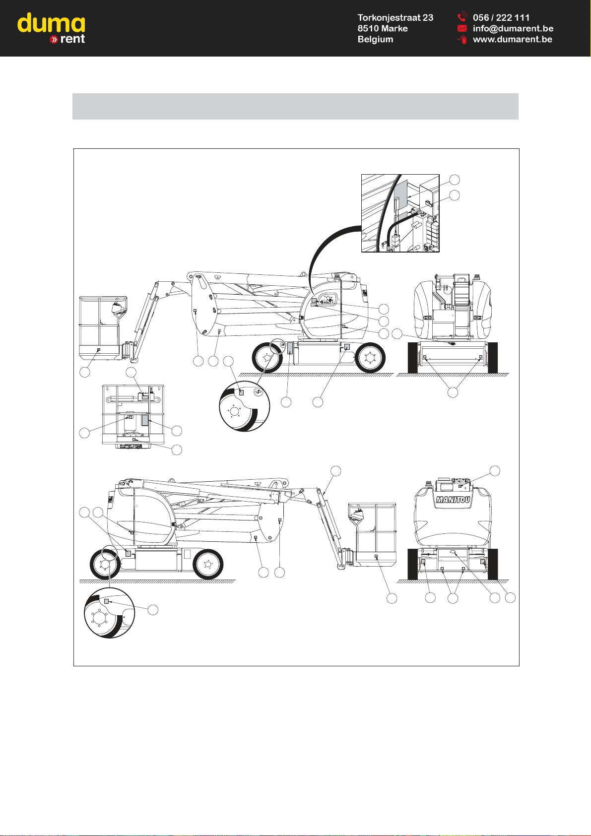
SAFETY DECALS
15
10
14
8
31214
1
13
7
814
12 14
4
5
9
12
714
1011
3
6
14
2
33
13
Page 23

1 - 19
DESCRIPTION
1 - WHITE ARROW
2 - BLACK ARROW
3 - LOAD PER WHEEL
4 - MANUAL CONTROL PROCEDURE
5 - MANUAL CONTROL PROCEDURE FOR ROTATING JIB
6 - BLADE SAFETY INSTRUCTIONS
7 - WASHING RECOMMENDATIONS
8 - ANCHORING HOOK
9 - BASKET INSTRUCTIONS / LOAD CAPACITY
10 - REPLACING THE BATTERIES
11 - BATTERY CUT-OFF / DANGER BATTERY CHARGE / 230 VOLT 16 A SOCKET
12 - DANGER KEEP AWAY
13 - RISK OF SHEARING
14 - RISK OF CRUSHING
15 - POSITION OF THE PLATFORM KEY
Page 24
1 - 20
679307
2
3
2
1
3
1
1
4
MEANING
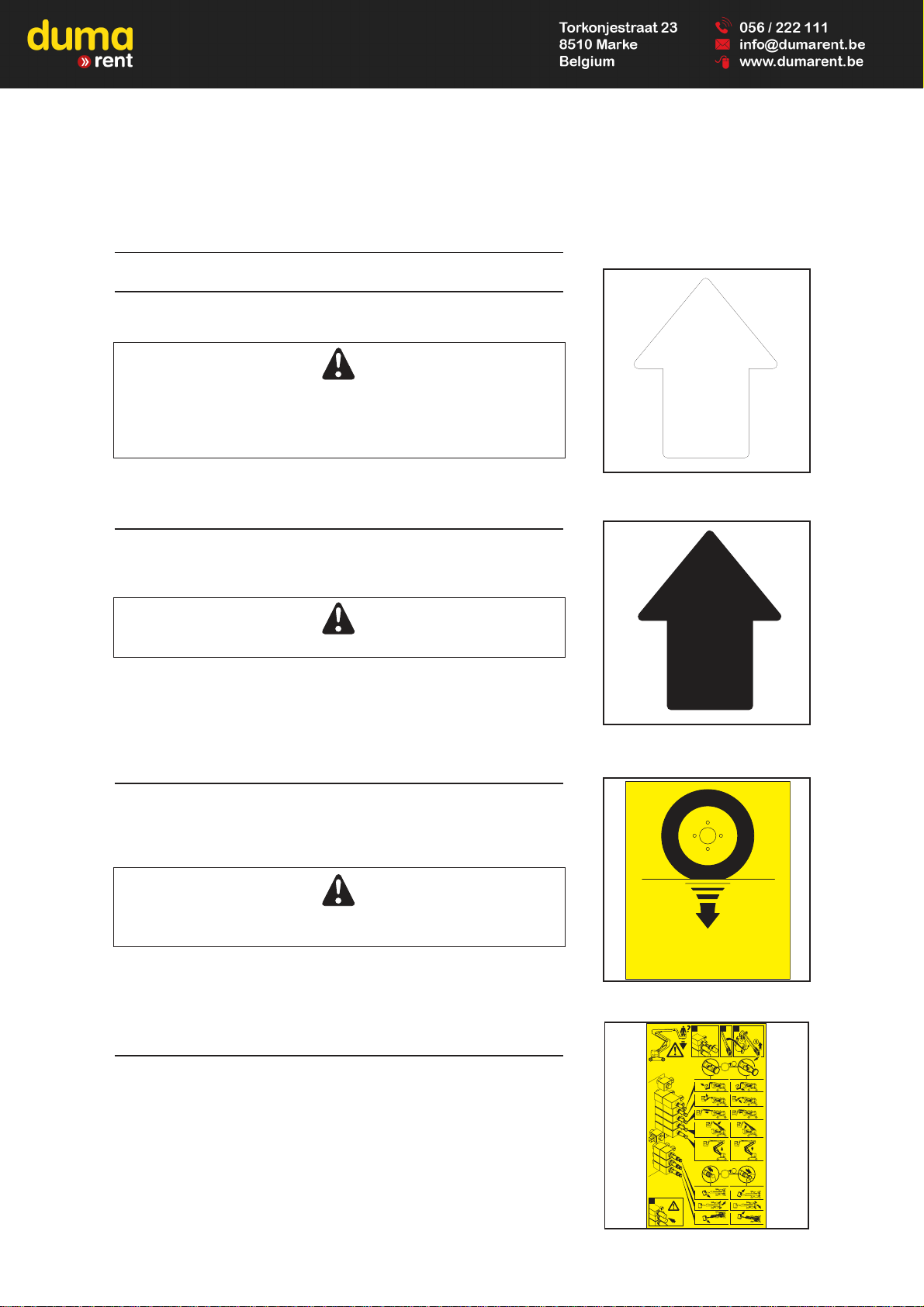
1. WHITE ARROW
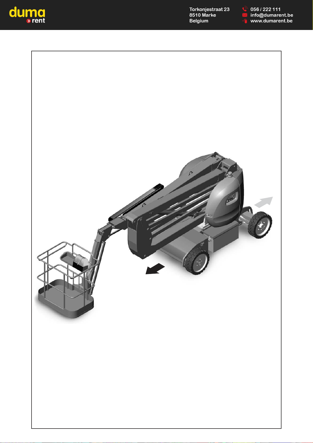
This indicates the direction of travelling when moving forwards.
When the turret assembly, the arms assembly and the basket make a 180°
rotation with respect to the chassis, the travelling controls are reversed.
Identify the forward direction by looking at the arrows on the chassis and on
the basket control console.
2. BLACK ARROW
This indicates the direction of travelling when reversing.
Same: white arrow
NB: As on the basket console and the chassis, the white arrows indicate
forward travelling and the black arrows reverse travelling.
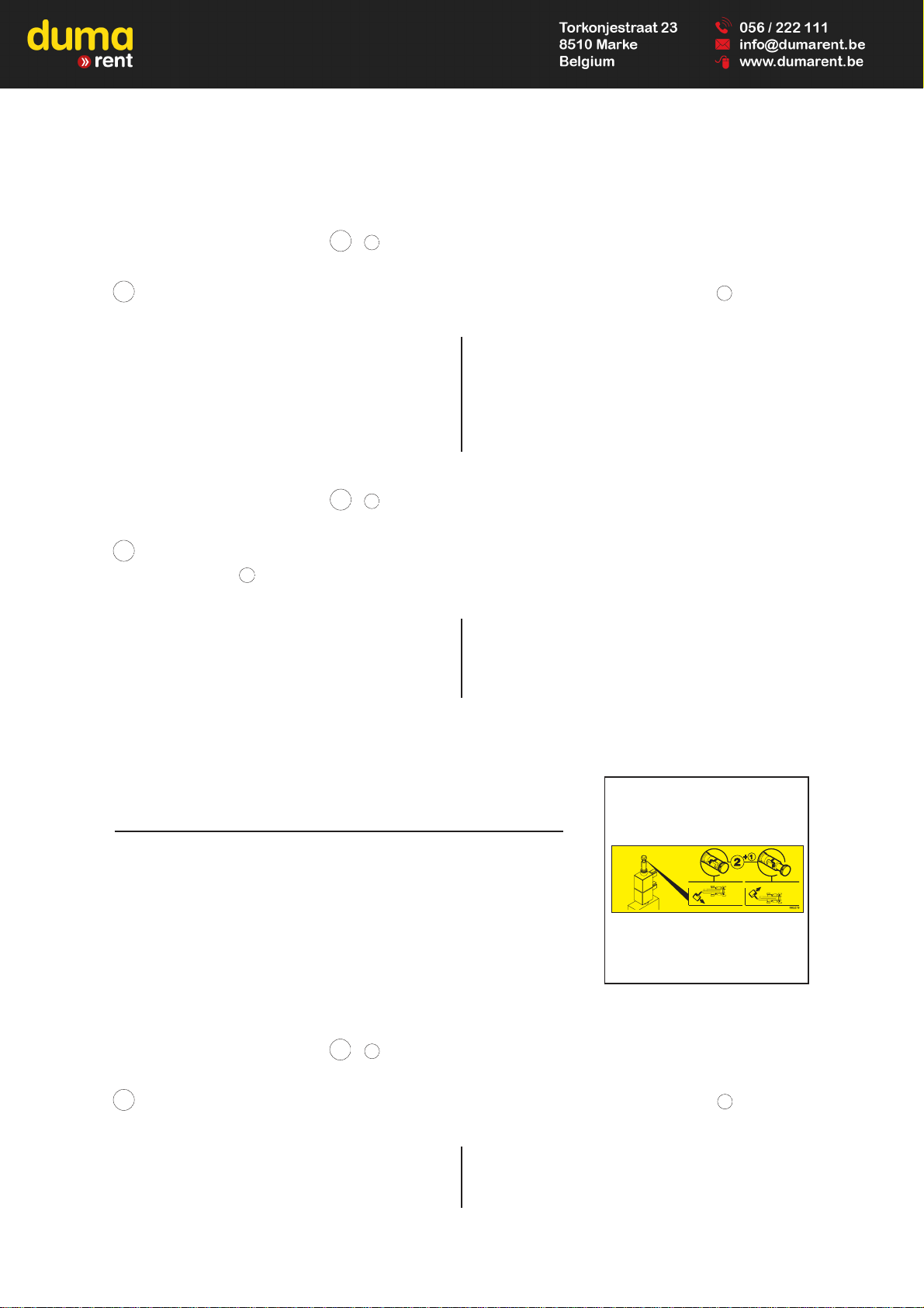
3. LOAD PER WHEEL
This indicates the maximum load on one wheel and the load the wheel will
exert on the ground (see 2 - DESCRIPTION: CHARACTERISTICS for the
piercing value).
Before using the platform, identify the type of ground and find out its ability to
resist being pierced.
NB: The weight must be visible on the platform.
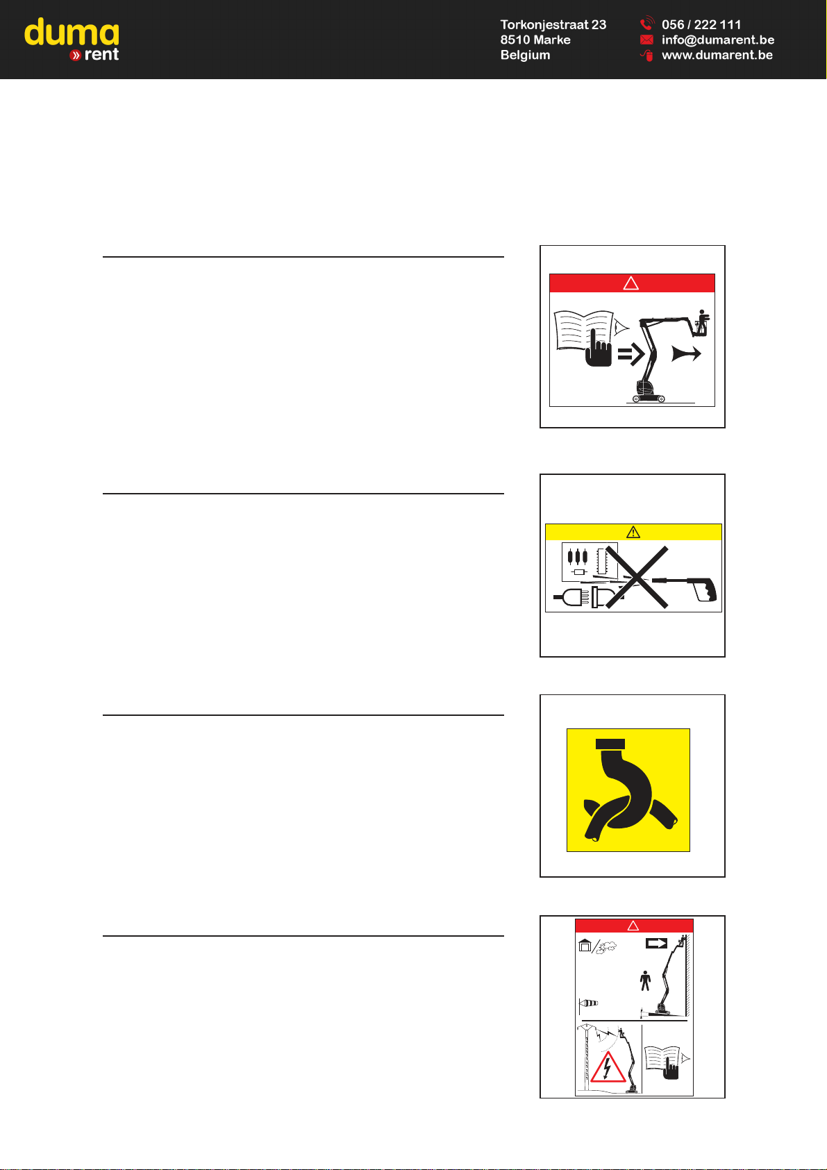
4. MANUAL CONTROL PROCEDURE
This describes the procedure for: lowering or turning the basket, turning the
turret and directing the wheels using the pump and the manual controls.
PROCEDURE :
Thumbnail 1 : Unscrew and remove the protective cover over the indexed
controls.
Thumbnail 2 : Pick up the lever.
Thumbnail 3 : Position the lever on the manual pump.
XXXXXX
XXXX Kg
XXXX Lbs
Page 25
1 - 21
Association of the two operations
2 + 1 :
Depending on the movements desired:
2 - Push in and lock the wheel (left-hand bubble) OR pull out and lock the wheel (right-hand bubble) + 1 - Pump.
This enables you to perform:
Top left column downwards, Top right column downwards,
The five movements below: The five movements below:
- Raise the basket and the pendular arm - Lower the basket and the pendular arm
- Raise the pendular arm (the basket stays horizontal) - Lower the pendular arm (the basket stays horizontal)
- Extend the telescope - Retract the telescope
- Raise the upper arm - Lower the upper arm
- Raise the intermediate arms - Lower the intermediate arms
Association of the two operations
3 + 1 :
Depending on the movements desired:
3 - Push the wheel in and hold it in this position (left-hand bubble) OR pull the wheel out and hold it in this position
(right-hand bubble) + 1 - Pump.
This enables you to perform:
Top left column downwards, Top right column downwards,
The three movements below: The three movements below:
- Basket rotation right - Basket rotation left
- Point wheels left - Point wheels right
- Turret rotation right - Turret rotation left
Thumbnail 4: Screw on the protective cover for the indexed controls.
5. MANUAL CONTROL PROCEDURE FOR ROTATING
JIB (3D PLATFORMS)
This describes the procedure for turning the pendular arm / basket assembly.
PROCEDURE (see sticker N° 4):
Thumbnail 1 : Unscrew and remove the protective cover over the indexed
controls.
Thumbnail 2 : Pick up the lever.
Thumbnail 3 : Position the lever on the manual pump.
Association of the two operations
2 + 1 :
Depending on the movements desired:
2 - Push in and lock the wheel (left-hand bubble) OR pull out and lock the wheel (right-hand bubble) + 1 - Pump.
This enables you to perform:
Left-hand column, Right-hand column,
The movements below: The movements below:
- Rotation of the basket assembly - Rotation of the basket assembly
and pendular arm to the right and pendular arm to the left
Page 26
1 - 22
230 Kg = 70 Kg +
508 Lbs = 155 Lbs +
2
!
12,5 m/s (45 km/h)
3°
400 N
(40 Kg - 90 Lbs)
679309
679311
!
6. BLADE SAFETY INSTRUCTIONS
Take note of the safety and operating instructions before you start the
platform.
7. WASHING RECOMMENDATIONS
It is strictly forbidden to direct a pressure washer’s nozzle over the control
buttons and electrical components.
8. ANCHORING HOOK
This sticker indicates the anchoring points for tying down the platform on the
flatbed of a truck.
9. BASKET INSTRUCTIONS / LOAD CAPACITY
This describes three points:
- The platform’s capabilities for use indoors and out of doors.
- The risk of electric shock.
- An invitation to read the instructions for more detailed information on the
safety instructions.
NB: Each platform has its own capabilities: please refer to this sticker for your
particular platform.
598892 A
598895
XXX
XXX
XXX
XX
Page 27
1 - 23
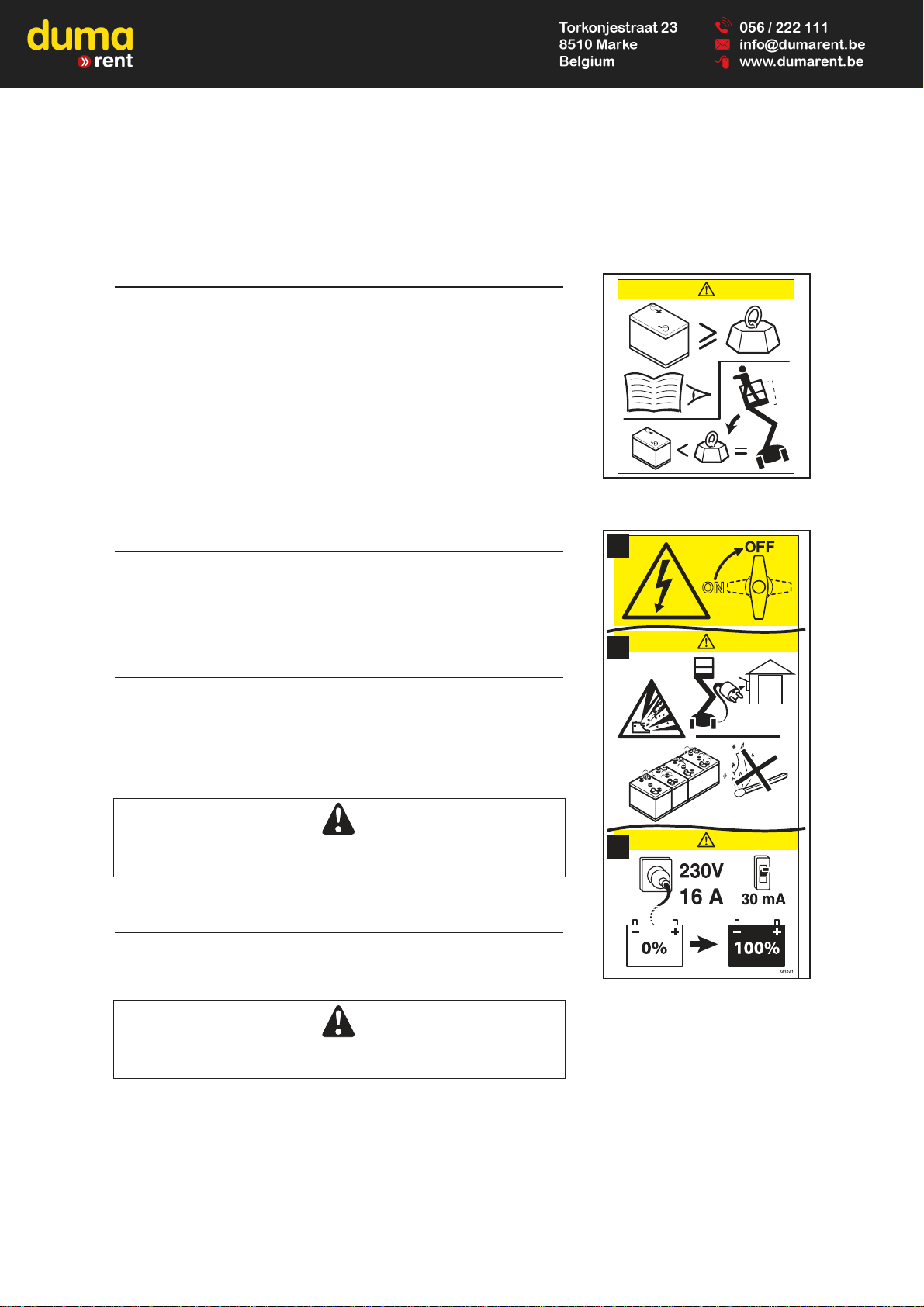
10. REPLACING THE BATTERIES
This indicates that the weight of the new batteries must be greater than or
equal to those you are replacing. If this instruction is not observed, the
platform’s stability will be compromised.
11 A. BATTERY CUT-OFF
This indicates the position of the battery cut-out and its effect:
Position OFF: le courant ne passe pas.
Position ON: le courant passe.
11 B. DANGER BATTERY CHARGE
This describes three points:
- The risk of explosion when batteries are charging.
- Batteries must be charged outside or in a well-ventilated area.
- The risk of explosion during charging, due to a spark, a flame or a schortcircuit.
Do not smoke near the access platform when the batteries are being
charged.
11 C. 230VOLT 16A SOCKET
This informs you that to charge the batteries you must connect the charger to
a socket supplying 230 Volts with an intensity of 16 Amps.
The socket must be protected by a differential circuit breaker
with 30mA protection.
677856
A
B
C
Page 28
1 - 24
12. DANGER : KEEP AWAY
It is strictly forbidden to cross under or park under the structure (arms,
scissors, pendular arm, basket, etc.) and in the area over which the platform
operates.
13. RISK OF SHEARING
It is strictly forbidden to place your fingers, or any other part of the body, in
the parts of the lifting system (arms, scissors, pendular arm, etc.): risk of
being cut or crushed.
14. RISK OF CRUSHING
It is strictly forbidden to park in this area when the platform is moving
(rotating, etc.). The elements on which the stickers are affixed could collide
with you, with the risk of crushing you.
15. POSITION OF THE PLATFORM KEY
The spare keys for the access platform (ignition key, control selector key, key
for locking casings...) are stored in the place provided for the purpose.
679452
679451
679450
Page 29

2 - 1
2 - DESCRIPTION
2 - DESCRIPTION
Page 30

2 - 2
Page 31

2 - 3
CONTENTS
PLATFORM IDENTIFICATION
CHARACTERISTICS
DIMENSIONS 120 AETJ L
DIMENSIONS 150 AETJ C
DIMENSIONS 150 AETJ L
DIMENSIONS 170 AETJ L
PLATFORM OPERATION
CONTROL INSTRUMENTATION
GROUND BACKUP AND MAINTENANCE STATION
BASKET COMMAND AND CONTROL STATION
USE OF THE PLATFORM
RESCUE PROCEDURE
2 - 4
2 - 5
2 - 10
2 - 12
2 - 14
2 - 16
2 - 19
2 - 22
2 - 26
2 - 33
2 - 37
2 - 41
Page 32

2 - 4
It is our policy to improve our products constantly. Certain modifications may
be made to our range of platforms without our being required to advise our
customers.
On any order for replacement parts or for any technical information, please
always specify:
NB: To be able to provide all these numbers more easily, we recommend that
you write them down in the locations provided for this on receipt of the
platform.
PLATFORM MANUFACTURER’S PLATE (FIG. A)
- Type
- Serial No.
- Year of manufacture
LOCATION OF THE MANUFACTURER’S PLATE (FIG. B)
The manufacturer’s plate is fastened to the rear of the chassis on the lefthand side.
PLATFORM IDENTIFICATION
A
B
Page 33

2 - 5
ELECTRIC PUMP
- Power supply 48 V
- Power 3,6 KW
- Cubic capacity 4,8 cm3
- Pressure 200 bar
ELECTRICAL WHEELS MOTORS
- Type T 17 - 2 KW
ELECTRICAL CIRCUIT
- Battery 48 V - 300 Ah(150AETJC - 150AETJL -
170AETJL)
48 V - 240 Ah (120AETJL)
- Charger 45 Ah (Mono)
FUSES
- Main card (Base control box ): 5 A (1 Fig A) and 15 A (2 Fig A)
- Power (Contactor plate): 325 A (3 Fig B)
- Electric pump (Variable speed drive plate): 100 A (4 Fig C)
CHARACTERISTICS
3
4
1
2
A
B
C
Page 34

2 - 6
TYRES
Wheel nut tightening torque ; front wheels 34 daNm
Wheel nut tightening torque ; rear wheels 22 daNm
120 AETJ L
SPECIFICATIONS
- Use Indoors and Outdoors
- Capacity 200 Kg including 2 people
- Maximum authorized wind speed 45 Km/h
- Control system Hydro-electric
- Turret rotation 355°
- Working speed 0,6 km/h
- Speed in transport 5 km/h
- Working height 11950 mm
- Height of floor 9950 mm
- Max. offset 6870 mm
- Weight of the access platform
• Unloaded 5050 kg
• In nominal load 5250 kg
- Number of speed 2
- Negotiable slope 30%
- Max. permissible tilt 5% or 3°
LOAD PER WITH MAX. LOAD
CONTACT SURFACE
DIMENSIONS TYPE
TYRE UNLADEN
+ D
OFF-CENTRING ON 1 WHEEL
OF 1 WHEEL WITH GROUND
STAMPING
FRONT REAR FRONT / REAR
600 X 190 TYRE
2370 KG 2680 KG 2800 KG - CM
2
- DAN/CM
2
Page 35

2 - 7
TYRES
Wheel nut tightening torque ; front wheels 34 daNm
Wheel nut tightening torque ; rear wheels 22 daNm
150 AETJ C
SPECIFICATIONS
- Use Indoors and Outdoors
- Capacity 200 Kg including 2 people
- Maximum authorized wind speed 45 Km/h
- Control system Hydro-electric
- Turret rotation 355°
- Working speed 0,6 km/h
- Speed in transport 5 km/h
- Working height 14990 mm
- Height of floor 12990 mm
- Max. offset 7600 mm
- Weight of the access platform
• Unloaded 6700 kg
• In nominal load 6900 kg
- Number of speed 2
- Negotiable slope 23%
- Max. permissible tilt 5% or 3°
LOAD PER WITH MAX. LOAD
CONTACT SURFACE
DIMENSIONS TYPE
TYRE UNLADEN+ OFF-CENTRING ON 1 WHEEL
OF 1 WHEEL WITH GROUND
STAMPING
FRONT REAR FRONT / REAR
600 X 190 TYRE
2930 KG 3770 KG 3600 KG - CM
2
- DAN/CM
2
Page 36

TYRES
Wheel nut tightening torque ; front wheels 34 daNm
Wheel nut tightening torque ; rear wheels 22 daNm
2 - 8
150 AETJ L
SPECIFICATIONS
- Use Indoors and Outdoors
- Capacity 230 Kg including 2 people
- Maximum authorized wind speed 45 Km/h
- Control system Hydro-electric
- Turret rotation 355°
- Working speed 0,6 km/h
- Speed in transport 5 km/h
- Working height 15280 mm
- Height of floor 13280 mm
- Max. offset 7810 mm
- Weight of the access platform
• Unloaded 5910 kg
• In nominal load 6140 kg
- Number of speed 2
- Negotiable slope 26%
- Max. permissible tilt 5% or 3°
LOAD PER WITH MAX. LOAD
CONTACT SURFACE
DIMENSIONS TYPE
TYRE UNLADEN
+ D
OFF-CENTRING ON 1 WHEEL
OF 1 WHEEL WITH GROUND
STAMPING
FRONT REAR FRONT / REAR
600 X 190 TYRE
1240 KG 1715 KG 3600 KG 283 CM
2
12,5 DAN/CM
2
Page 37

2 - 9
TYRES
Wheel nut tightening torque ; front wheels 34 daNm
Wheel nut tightening torque ; rear wheels 22 daNm
170 AETJ L
SPECIFICATIONS
- Use Indoors and Outdoors
- Capacity 200 Kg including 2 people
- Maximum authorized wind speed 45 Km/h
- Control system Hydro-electric
- Turret rotation 355°
- Working speed 0,6 km/h
- Speed in transport 5 km/h
- Working height 16910 mm
- Height of floor 14910 mm
- Max. offset 9430 mm
- Weight of the access platform
• Unloaded 6910 kg
• In nominal load 7110 kg
- Number of speed 2
- Negotiable slope 22%
- Max. permissible tilt 5% or 3°
LOAD PER WITH MAX. LOAD
CONTACT SURFACE
DIMENSIONS TYPE
TYRE UNLADEN+ OFF-CENTRING ON 1 WHEEL
OF 1 WHEEL WITH GROUND
STAMPING
FRONT REAR FRONT / REAR
600 X 190 TYRE
1520 KG 1935 KG 4200 KG - CM
2
- DAN/CM
2
Page 38

2 - 10
DIMENSIONS 120AETJ L
D
E
B
C
F
H
G
I
A1A1
C1
A
A 5520
A1 3930
B 2000
C 1995
C1 2210
D 1500
E 153
F 2640
G 1870
H 3960
I 4520
Page 39

2 - 11
G1
G2
H2 H1
G3
H3
G4
H4
12
11
10
9
8
7
6
5
4
3
2
1
4567
13
3210123
52332 674
G1 2350
G2 3105
G3 6370
G4 5640
H1 9950
H2 8795
H3 4775
H4 545
Page 40

2 - 12
DIMENSIONS 150AETJ C
D
E
F
H
G
I
B
C1
A1
C
A
A 6050
A1 4400
B 2000
C 1965
C1 2080
D 1500
E 143
F 2640
G 1870
H 3960
I 4820
Page 41

2 - 13
G1
G2
H2 H1
G3
H3
G4
H4
897
12
11
10
9
8
7
6
5
4
3
2
1
456789
16
15
14
13
3210123
2332
G1 2665
G2 3425
G3 7105
G4 6300
H1 12985
H2 11835
H3 7165
H4 235
Page 42

D
E
FH
G
I
B
A1
A
C
C1
2 - 14
DIMENSIONS 150AETJ L
A 5960
A1 4400
B 2000
C 1970
C1 2080
D 1750
E 143
F 2880
G 1970
H 4270
I 4890
Page 43

G1
G2
H2 H1
G3
H3
G4
H4
89
12
11
10
9
8
7
6
5
4
3
2
1
456789
16
15
14
13
3210123
52332
2 - 15
G1 2660
G2 3420
G3 7310
G4 6500
H1 13275
H2 12120
H3 7165
H4 205
Page 44

D
E
FH
G
I
B
A1
A
C
C1
2 - 16
DIMENSIONS 170AETJ L
A 6840
A1 5120
B 2000
C 1970
C1 2040
D 1750
E 143
F 2890
G 2005
H 4300
I 5600
Page 45

G1
G2
H2 H1
G4
910
10
12
11
10
9
8
7
6
5
4
3
2
1
456789
16
17
15
14
13
3210123
2332 64
H4
G3
H3
2 - 17
G1 2840
G2 3600
G3 8930
G4 8130
H1 14910
H2 13750
H3 7160
H4 270
Page 46

2 - 18
Page 47

2 - 19
PLATFORM OPERATION
DESCRIPTION
- This machine is a mobile platform for lifting people. It consists of a work platform fastened to the end of a pendular arm,
itself fastened to the end of a telescopic arm and the whole assembly is fastened to an articulated arm structure.
- MANITOU lifting platforms are solely for use for bringing people, and their tools and supplies (within the authorised
weight limit, please refer to the paragraph “SPECIFICATIONS”), to a desired working height, to reach hard-to-access
locations over installations and buildings.
- The lifting platform is equipped with a control station in the basket. From this, the operator can drive or move the
machine forwards or backwards. He can raise or lower all the arms, extend or retract the telescopic arm and turn the
turret or the basket right or left. The basket, arms and turret assembly can rotate within an angle of 355 degrees, noncontinuously, to the right and the left of its folded position.
- The lifting platform is also equipped with a ground backup and maintenance station which can control all lifting
functions except travelling The base controls are only to be used in an emergency to bring the operator back to ground
level if he is incapable of doing this himself.
- The ground backup and maintenance station and the basket control station must be checked by the operator every day
to ensure that they work properly.
The characteristics, safety instructions and rescue procedure stickers are affixed to the machine.
The operator must take note of these and understand their contents. To avoid any risk of misinterpreting
the pictograms, please refer to the Paragraph “SAFETY STICKERS” in Chapter 1 – SAFETY ADVICE AND
INSTRUCTIONS.
- The lifting platform’s movements are powered by a hydraulic pump, operated by a battery-powered electric motor. The
hydraulic components are controlled by electro-valves actuated by contactors and the manipulator.
- The base or basket console’s controls are via changeover contactors and are either in “Run” or “Stop” mode.
- The base console is equipped with a so-called “Dead Man’s” push button. This must be pressed in at the same
time a contactor is switched over. Releasing it stops the movement.
- The lifting platform is a two-wheel drive machine driven by an electric motor on each wheel. The drive wheels have
spring-operated, hydraulically released brakes. These brakes tighten automatically as soon as the travelling
manipulator is returned to the neutral position.
- The lifting platform can lift up to the limit of its capacities (seer “SPECIFICATIONS” in this Chapter). Having a maximum
capacity load or less in the basket will still enable you to move in any position, provided that the machine on ground
with a slope of no more than 3°.
GENERAL
- In the following pages, you will find all the information required for using the machine, including the platform’s
operating, driving, parking, loading and transport instructions.
Page 48

2 - 20
SAFETY
SLOPE
When the access platform has reached the maximum authorised
inclination (see chapter : CHARACTERISTICS), the LED 23* on the
basket console flashes regularly. Furthermore, the beeper 33* in the
basket also sounds intermittently.
All "AGGRAVATING" movements - raising the arms, extending the
telescope movements are prohibited for safety reasons .
To restore these functions, only perform "disaggravating" movements :
- Return to safe position by retracting the telescope and lowering the arms:
then position the platform on a more horizontal surface so that you can
raise the arms and extend the telescope.
OVERLOAD
When the access platform has reached the maximum authorised weight (see
chapter : CHARACTERISTICS) in the basket. The overload LED at the
ground backup and maintenance station 3* and the basket console 22* flash
regularly. The beeper 33* in the basket sounds constantly. All movements are
prohibited for safety reasons.
To restore these functions :
- Lighten the basket by removing the item(s) causing the overload,
OR,
- Ask someone at ground level to lower the basket under manual control
(see “RESCUE PROCEDURE” in this Chapter and “SAFETY STICKERS”
in Chapter 1 “SAFETY ADVICE AND INSTRUCTIONS”).
* : the above references are the same as those used in the description
of these components in the following pages.
22
23
33
3
Page 49

2 - 21
NB :
INCOHERENCE of OVERLOAD SENSORS,
LOW ARM position and TELESCOPE extension
/ retraction.
This memo is to inform you that the slope and overload LEDs
may, in certain situations, be activated intermittently and the
beeper may sound constantly, for reasons other than excessive slope position or overloaded basket.
For your safety, the access platform is equipped with two overload
sensors. If only one sensor is activated, the access platform is blocked, the display (see Ref. 7 on the following pages) displays fault
code "F02004". At the same time :
on the basket console : on the base console :
- Beeper 33* sounds constantly. - LED 3* flashes regularly.
- LED 22* flashes in sets of 5 flashes - LED 4* flashes in sets of 5 flashes
every 2 seconds. every 2 seconds.
For your safety, the access platform is equipped with two sensors for the low arm position and two for telesco-
pe extension / retraction. If only one sensor is activated in either of these functions, the display (see Ref. 7
on the next page) displays fault code "F02005". At the same time :
on the basket console : on the base console :
- Beeper 33* remains silent. - LED 4* flashes in sets of 5 flashes
- LED 22* flashes in sets of 5 flashes every 2 seconds.
every 2 seconds.
If the fault continues to be displayed, immobilise the platform and make the necessary repairs.
Consult your dealer.
* : the above references are the same as those used in the description of these components in the following
pages.
4
Page 50

2 - 22
CONTROL INSTRUMENTATION
A- GROUND BACKUP AND MAINTENANCE STATION
17
16
18
19
20
15
8
10
14
3
4
5
6
9
11
12
13
1
2
7
Page 51

2 - 23
A- GROUND BACKUP AND MAINTENANCE STATION
1 - EMERGENCY STOP
2 - KEY-OPERATED CONTROL SELECTOR SWITCH AT GROUND LEVEL OR IN THE
BASKET
3 - OVERLOAD LAMP
4 - "MAINTENANCE MACHINE" LAMP
5 - "STATE OF CHARGE OF THE BATTERY" LAMP
6 - "DEAD MAN" BUTTON
7 - BATTERY CHARGE INDICATOR AND THE HORAMETER
8 - PLATFORM ROTATION CONTACTOR
9 - RAISE AND LOWER CONTACTOR OF THE EXTENSION ARM
10 - ROTATION CONTACTOR FOR ROTATED JIB (OPTION 3D)
11 - TELESCOPE OUTPUTS AND INPUTS CONTACTOR
12 - RAISE AND LOWER CONTACTOR OF THE SUPERIOR ARM
13 - RAISE AND LOWER CONTACTOR OF THE INFERIOR ARM
14 - TURRET ROTATION CONTACTOR
15 - INCLINATION CONTACTOR OF THE PLATFORM
16 - BATTERY SWITCH
17 - FLASHING LIGHT (OPTION)
18 - SLOPE SENSOR
19 - SOUND ALARM HORN
20 - BLOCKAGE OF THE TURRET ROTATION
Page 52

2 - 24
CONTROL INSTRUMENTATION
B - BASKET COMMAND AND CONTROL STATION
25
27
28
26
24
34
34
29
30
22
23
33
31
21
32
35
Page 53

2 - 25
B - BASKET COMMAND AND CONTROL STATION
21 - EMERGENCY STOP
22 - OVERLOAD LAMP AND VARIATOR DEFECTS
23 - SLOPE LAMP
24 - SOUND ALARM HORN
25 - CONTROL SWITCH
26 - CONTACTOR OF SELECTION OF ROTATION
27 - PLATFORM INCLINATION CONTACTOR
28 - EXTENSION ARM LIFTING / LOWERING CONTACTOR
29 - TELESCOPE OUTPUTS / INPUTS CONTACTOR
30 - SUPERIOR ARM LIFTING / RAISING CONTACTOR
31 - INFERIOR ARM LIFTING / RAISING CONTACTOR
32 - TRAVELLING CONTACTOR
33 - ALARM BUZZER
34 - SAFETY HARNESS ATTACHMENT POINTS
35 - CONSOLE PROTECTIVE COVER
NB: The terms RIGHT-LEFT-FRONT-REAR apply to a user on the nacelle platform in the transportation position
and looking straight ahead.
Page 54

2 - 26
1 - EMERGENY STOP
This red mushroom-head switch cuts off all the machine’s movements in the
event of any anomalies or danger.
- Press the knob to stop the machine’s movements.
- Turn the knob a quarter of a turn to the right to restore the power (the switch
automatically returns to its initial position).
This command takes priority in all circumstances, even when control is swit-
ched to the access platform.
If the Emergency Stop is pressed,
movements may stop very abruptly.
2 - KEY-OPERATED CONTROL SELECTOR SWITCH AT
GROUND LEVEL OR IN THE BASKET
This 3-position BASKET / BASE control station, with the Stop position in the
centre, powers the basket control console when it is set in the PLATFORM
position. When the selector is in the BASE position, power to the console in
the BASKET is cut off and only the base controls can be used.
A : - Functions are controlled from the basket command and control sta-
tion.
B : - Neutral position : the platform controls are idle (remove the key in
this position)
C : - Functions are controlled from the ground backup and maintenance
station.
3 - O
VERLOAD LAMP
If the basket is overloaded, the LED flashes intermittently (See : ACCESS
PLATFORM OPERATION– SAFETY INSTRUCTIONS ).
GROUND BACKUP AND MAINTENANCE STATION
B
C
A
1
2
3
Page 55

2 - 27
4 - “MAINTENANCE MACHINE” LAMP
- THIS LAMP HAS TWO FUNCTIONS:
1 This lamp is controlled by a timer, which brings it on every 50 hours
worked (Counting of the number of hours the hydraulic pump has
operated).
When the lamp is on (fixed LED), this mean that the machine must be
serviced (see chapter "MAINTENANCE TABLE").
NB: To deactivate this light, see 7 “Battery charge and timer indicator
lights”.
2 In the event of a fault, the number of flashes indicates the type of fault
detected by the variator:
- 1 flash : Variator parameter defect
- 2 flashes : Command activated before the use
- 3 flashes : Variator in short-circuit
- 4 flashes : Defect contactors of power
- 5 flashes : Sensor synchronisation fault
- 6 flashes : Accelerator, control switch, potentiometer or wire of speed
sensor
- 7 flashes : Battery discharged
- 8 flashes : Variator temperature over high
- 9 flashes : Bobbin contactor in short-circuit
-12 flashes : Defect bus connection.
If the LED flashes permanently, stop the access platform.
Consult your dealer
5 - “STATE OF CHARGE OF THE BATTERY” LAMP
The lamp changes of colors according to the state of the battery charge:
The red led:
- The charger is on the initial phase of charge.
The yellow led:
- The battery is charged at 80% of charge.
The green led:
- The battery is charged.
BATTERY AUTONOMY
- The following functions will be switched off when you reach 20% of
load, in working or transport speed position, at the ground backup and
maintenance control station or basket command and control station :
• Raise intermediate arms
• Raise upper arm
• Extend telescope
6 - “DEAD MAN” BUTTON
As a safety measure, this button must be held down constantly to activate the
various lifting and rotation functions.
6
4
5
Page 56

2 - 28
7 - BATTERY CHARGE INDICATOR AND THE
HORAMETER
A - BATTERY CHARGE INDICATOR
· BATTERY CHARGED
- All the bars are displayed (dark).
· BBATTERY DISCHARGED
- Only two bars are still displayed, meaning that you must proceed to
recharge the batteries (See the Chapter "MAINTENANCE INTERVALS").
NB: You must not drop below a battery charge level of 20%; otherwise the
batteries can deteriorate rapidly.
The following 2 timers are displayed on startup, but only the counter
with the "T" symbol is on during normal operation :
B - DAILY HORAMETRE INDICATOR
It indicates the total number of hours for all the movements made and can be
reset to zero.
C - PUMP AND TRACTION HORAMETRE INDICATOR
It indicates the total number of hours for all the movements made
D - FAULT DISPLAY
If the machine breaks down, a fault number is displayed (it will be stored in
memory and can be analysed) and the “machine maintenance” light 4 comes
on (flashing after faults have occurred).
If the fault continues to be displayed, immobilise the platform and make the
necessary repairs.
NB: For the descriptions and frequencies of the faults detected, see this
machine’s REPAIRS MANUAL.
Consult your dealer.
D
B
C
A
Page 57

2 - 29
RESETTING THE DAILY HORAMETRE TIMER TO ZERO
Proceed as follows:
- The platform must be in transport position (arms and telescope
completely folded),
- The platform must not be sloping,
- The platform must be in "Ground backup and maintenance station"
position, using selector 2 "key-operated control selector at ground level
or in the basket " and wait for the initialisation "Beep".
- Press 6, the "dead man button" and at the same time the two contactors
: 9 "contactor for raising and lowing the pendular arm" and 15 "basket
tilt contactor", until the counter is reset to zero.
NB: This operation should be done during the few seconds following
restoration of power to the electrical circuit.
RESET THE TIMER TO ZERO EVERY 50 HOURS OF OPERATION
This must be done after performing the maintenance described in the
Chapter: MAINTENANCE “EVERY 50 HOURS OF OPERATION”.
Proceed as follows:
- The platform must be in transport position (arms and telescope
completely folded),
- The platform must not be sloping,
- The platform must be in "Ground backup and maintenance station"
position, using selector 2 "key-operated control selector at ground level
or in the basket " and wait for the initialisation "Beep".
- Simultaneously press the “Dead Man’s” button 6 and contactors No. 12
(“upper arm raising and lowering contactor”) and 13 (“lower arm raising
and lowering contactor” until the MACHINE MAINTENANCE light 4
goes out (the timer is reset to zero).
NB: This operation should be done during the few seconds following
restoration of power to the electrical circuit.
6
2
12
9
15
13
4
Page 58

2 - 30
8 - PLATFORM ROTATION CONTACTOR
- This contactor is used to rotate the platform.
RIGHT ROTATION
- Place the base/basket switch in the base position, keep the "dead man"
button pushed and push the switch 8 to the right.
LEFT ROTATION
- Place the base/basket switch in the base position, keep the "dead man"
button pushed and push the switch 8 to the left.
9 - RAISE AND LOWER CONTACTOR OF THE EXTENSION ARM
- This contactor is used to raise or lower the extension arm.
LIFTING OF THE EXTENSION ARM
- Place the base/basket switch in the base position, keep the "dead man" button pushed and push the switch 9 upwards.
LOWERING OF THE EXTENSION ARM
- Place the base/basket switch in the base position, keep the "dead man" button pushed and push the switch 9
downwards.
10 - ROTATION CONTACTOR FOR ROTATED JIB (OPTION 3D)
- This contactor enables you to rotate the pendular arm.
RIGHT ROTATION
- Place the base/basket switch in the base position, keep the "dead man"
button pushed and push the switch 10 to the right.
LEFT ROTATION
- Place the base/basket switch in the base position, keep the "dead man"
button pushed and push the switch 10 to the left.
11 - TELESCOPE OUTPUTS AND INPUTS CONTACTOR
- This contactor enables you to extend and retract the telescope.
TELESCOPE EXTENSION
-
Place the base/basket switch in the base position, keep the "dead man"
button pushed and push the switch 11 to the left.
TELESCOPE RETRACTION
-
Place the base/basket switch in the base position, keep the "dead man" button
pushed and push the switch 11 to the right.
12 - RAISE AND LOWER CONTACTOR OF THE SUPERIOR ARM
- This contactor is used to raise or lower the superior arm.
LIFTING OF THE SUPERIOR ARM
-
Place the base/basket switch in the base position, keep the "dead man" button pushed and push the switch 12 upwards.
LOWERING OF THE SUPERIOR ARM
-
Place the base/basket switch in the base position, keep the "dead man" button pushed and push the switch 12 downwards.
10
8
9
11
12
Page 59

2 - 31
13 - RAISE AND LOWER CONTACTOR OF THE
INFERIOR ARM
- This contactor is used to raise and lower the inferior arm.
LIFTING OF THE SUPERIOR ARM
- Place the base/basket switch in the base position, keep the "dead man"
button pushed and push the switch 13 upwards.
LOWERING OF THE INFERIOR ARM
- Place the base/basket switch in the base position, keep the "dead man"
button pushed and push the switch 13 downwards.
14 - TURRET ROTATION CONTACTOR
- This contactor is used to rotate the turret.
RIGHT ROTATION
- Place the base/basket switch in the base position, keep the "dead man"
button pushed and push the switch 14 to the right.
LEFT ROTATION
- Place the base/basket switch in the base position, keep the "dead man"
button pushed and push the switch 14 to the left.
15 - INCLINATION CONTACTOR OF THE PLATFORM
- This contactor is used for the correction of the horizontality of the platform or
the complete re-folding of the platform in the transportation position.
CORRECTION OF THE PLATFORM UPWARD
- Place the base/basket switch in the base position, keep the "dead man"
button pushed and push the switch 15 upwards.
CORRECTION OF THE PLATFORM DOWNWARD
- Place the base/basket switch in the base position, keep the "dead man"
button pushed and push the switch 15 downwards.
16 - BATTERY SWITCH
The battery cut-out switch is located on the chassis on the ground backup
and maintenance station side.
IN THE ON POSITION
Turn the handle a quarter of a turn: current flows.
IN THE OFF POSITION
Turn the handle a quarter of a turn: current stops flowing.
Always set the battery cut-out to the OFF position when you are not using the
platform.
The sound alarm (see 19 - SOUND ALARM HORN) will come on if the
battery cut-out is left ON when the batteries are being charged.
15
16
14
13
Page 60

2 - 32
17 - FLASHING LIGHT (OPTION)
- The flashing alarm lamp turns on automatically when the platform is
travelling, or if a movement is carried out (Lifting, rotation,...).
18 - SLOPE SENSOR
- This sensor checks the platform’s inclination. When the platform
reaches the maximum authorised inclination (See the Chapter:
CHARACTERISTICS), the buzzer (33) sounds intermittently and all the
“AGGRAVATING” movements – raising the arms, extending the
telescope – are blocked. The LED (23) on the platform is lit.
NB: SLOPE TEST; set the platform on a flat surface in base control
position (see 2 – KEY-OPERATED CONTACTOR). Press the sensor
“PRESS TO TEST”, the buzzer should sound and the LED light up.
If the buzzer does not sound and the LED does not light, immobilise the
platform and make the necessary repairs.
19 - SOUND ALARM HORN
This sound alarm horn (fixed to the turret above the ground backup and
maintenance station box) is activated by pressing button 24.
The alarm will be activated if the BATTERY CUT-OUT is left on the ON
position when charging the batteries (see 16 – BATTERY CUT-OUT).
20 - BLOCKAGE OF THE TURRET ROTATION
- Put the spindle in the space foreseen for this effect.
- This spindle is used to lock the turret rotation when she is in position.
- She must be used when the access platform is transported by truck or by
another transport (train ...).
Do not forget to remove its during the use of the access platform.
NB: Releasing the pin; you may have to rotate the turret right or left to
free the pin to extract it from its location.
17
18
19
20
Page 61

2 - 33
21 - EMERGENCY STOP
This red mushroom-head switch cuts off all the machine’s movements in the
event of any anomalies or danger.
- Press the knob to stop the machine’s movements.
- Turn the knob a quarter of a turn to the right to restore the power (the switch
automatically returns to its initial position).
In any case, this control has priority, unless movements are controlled by the
ground backup and maintenance station.
If the Emergency Stop is pressed, movements may stop very abruptly.
22 - OVERLOAD LAMP AND VARIATOR DEFECTS
- THIS LAMP HAS TWO FUNCTIONS :
1 If the basket is overloaded, the LED flashes intermittently (See :
ACCESS PLATFORM OPERATION – SAFETY INSTRUCTIONS).
2 In case of fault, the number of flashes indicates the type of fault detected
by the variator (See: 4 - Lamp“MAINTENANCE MACHINE” p 2-17).
23 - SLOPE LAMP
When the access platform has reached the maximum authorised slope
the LED flashes intermittently See : ACCESS PLATFORM OPERATION
– SAFETY INSTRUCTIONS).
24 - SOUND ALARM HORN
- When button 24 is pressed, it activates the sound alarm horn 19 located on
the turret.
BASKET COMMAND AND CONTROL STATION
22
23
24
21
Page 62

2 - 34
25 - CONTROL SWITCH
NB: This control switch is progressive control, and gives a very high approa-
ch accurancy. Its use should be smooth and free of jerkes.
SAFETY TRIGGER
- This trigger (item A) of control control switch 25 must be continually
pushed in to perform movements from the operating of the access
platform.
26 - CONTACTOR OF SELECTION OF ROTATION
This contactor (26) has three positions. Switch it over to the movements
you desire and then use the manipulator (25).
PLATFORM ROTATION
- Switch the contactor 26 to the left (position I).
- Incline to the right or to the left the control switch 25 to orientate on the right
or on the left respectively.
TURRET ROTATION
- Switch the contactor 26 to vertical (position II).
- Incline to the right or to teh left the control switch 25 to orientate on the right
or on the left respectively.
ROTATION OF ROTATED JIB (3D PLATFORMS)
- Switch the contactor 26 to the right (position III).
- Incline to the right or to the left the contactor 25 in order to rotate on the right
or on the left respectively.
Before you make any rotation manoeuvres, check that there is enough space
between the platform or the turret and the various walls and installations.
I
II
III
I
II
III
26
26
I
II
III
26
A
25
Page 63

2 - 35
27 - 28 - 29 - 30 - 31 - 32 - MOVEMENT SELECTION
CONTACTOR
27 PLATFORM INCLINATION CONTACTOR
- Select the movement by pressing button 27; the movement remains
selected while the LED is lit (8 seconds).
- Push (forward) or pull (backward) the switch control 25 to raise or lower.
NB : The basket can only be tilted when the machine is in transport position.
(see USING THE ACCESS PLATFORM).
28 EXTENSION ARM LIFTING / LOWERING CONTACTOR
- Select the movement by pressing button 28; the movement remains
selected while the LED is lit (8 seconds).
- Push (forward) or pull (backward) the switch control 25 to raise or lower.
29 TELESCOPE OUTPUTS / INPUTS CONTACTOR
- Select the movement by pressing button 29; the movement remains
selected while the LED is lit (8 seconds).
- Push (forward) or pull (backward) the switch control 25 to go out or go back.
30 SUPERIOR ARM LIFTING / RAISING CONTACTOR
- Select the movement by pressing button 30; the movement remains
selected while the LED is lit (8 seconds).
- Push (forward) or pull (backward) the switch control 25 to raise or lower.
31 INFERIOR ARM LIFTING / RAISING CONTACTOR
- Select the movement by pressing button 31; the movement remains
selected while the LED is lit (8 seconds).
- Push (forward) or pull (backward) the switch control 25 to raise or lower.
32 TRAVELLING CONTACTOR
- Select the movement by pressing button 32 briefly (See NB for button B) ;
the movement stays selected as long as the LED is on (8 seconds).
- Push (forward) or pull (backward) the switch control 25 to advance or
retract.
DIRECTION:
- TO STEER TO THE LEFT OR THE RIGHT WITHOUT MOVING IN
TRAVELLING:
- Select the direction by pressing button B on the manipulator 25
(constant pressure) to the right or the left of the button to go
respectively right or left.
- TO STEER TO THE LEFT OR THE RIGHT WITH TRAVELLING:
- Select the direction by pressing button B on the manipulator 25
(constant pressure) to the right or the left of the button to go
respectively right or left.
- Push the manipulator (25) forwards or pull it backwards
respectively to go forward or reverse while steering the wheels.
NB : Pressing button B on the manipulator briefly also selects the travelling
movement, the movement stays selected as long as the LED (same as
contactor 32) is on (8 seconds).
25
B
27
28
29
32
30
31
Page 64

2 - 36
33 - ALARM BUZZER
- This buzzer sounds when the machine is in either of the critical
situations below:
- Case 1 ; INTERMITTENCE : (See : ACCESS PLATFORM
OPERATION - SAFETY INSTRUCTIONS).
- Case 2 ; CONTINUOUS : (See : ACCESS PLATFORM
OPERATION - SAFETY INSTRUCTIONS).
34 - SAFETY HARNESS ATTACHMENT POINTS
- These attachment points should be used to fasten the harnesses when
operators are in the basket.
NB: See Chapter 1 - “SAFETY ADVICE AND INSTRUCTIONS”.
35 - CONSOLE PROTECTIVE COVER
Once opened, this retractable casing protects the control panel from bad
weather and flying particles from various types of work.
After each day of platform use or during work where there is a risk of flying
particles, close the protective casing.
33
34
34
35
Page 65

2 - 37
DISPLACEMENT TRANSPORT MODE / WORKING MODE
Before moving and using the machine, remove the turret blocking
system 1 (see Fig. A).
The contactor 2 (Fig. B) should be in the position A (transfer of commands on the
desk of the platform).
The access platform has two modes of displacements: the transport mode (Fig.
D) and the working mode (Fig.E) (Direction of advance (Fig. C).
- Transport mode: the access platform arms are in low position. This mode is
used to move at high speed and go beyond the slope of the machine (Fig. D)
(See chapter : CHARACTERISTICS).
- Working mode: One or many arms of the access platform are lifted or the
telescope is gone out. In this mode, the travelling are made with a small speed,
the safeties for the slope and the overload are activated. (Fig. E).
No movement over terrain with a slope greater than the authorised inclination
(see the Chapter: CHARACTERISTICS) or with deformations likely to make the
platform overturn or with the jib higher than horizontal when the machine
is on an unstable surface.
Before driving the platform, ensure that the basket control station is correctly
over the drive wheels; if it is over the steering wheels, the controls will be
reversed compared to the machine’s direction of travel.
USE OF THE PLATFORM
TRANSPORT POSITION
TRANSPORT MODE
REAR
TRAVELLING
FRONT
TRAVELLING
A
2
1
A
B
C
D
WORKING MODE
E
Page 66

2 - 38
TRANSPORT
/ WORK SPEED MODE LIMITATION
The pendular arm can raise and lower in transport
speed mode with the telescope retracted.
Details on changing from transport speed to
working speed:
Extend the telescope less than 2cm and the lower
arms to the stop (raised < 5cm); over either of
these values, the platform switches to working
speed mode.
INSTALLATION ON THE WORK SITE AND LIFTING
The platform has been designed to work on a flat, horizontal surface: it is important to clear the area where the platform
will operate.
Make sure you are familiar with the instrumentation at the ground backup and maintenance station and the
basket control station, described in the pages above, particularly the warnings indicating the risks linked to
performing certain movements.
- Move the access platform into its working area.
- If necessary, load the equipment and the supplies, distribute the load uniformly (arrange it in a way so as not to
inconvenience the user and avoid any items falling off).
- Climb into the access platform.
It is strongly recommended to wear a safety helmet and harness.
During maneuvres of the access platform (raise, rotate, etc, ...), keep looking above and about you. Watch out in parti-
cular for electric cables and any other objects that may be located in the volume in which the access platform moving.
LOWERING
When the work has been completed : lower the telescope and the arm, returning the machine to the transportation
position.
Watch out carefully for people on the ground when lowering the access platform
STOPPING OF THE ACCESS PLATFORM
When the platform is not being used, switch off the power supply by setting the key-operated contactor to the
Neutral position (see 2 – KEY-OPERATED CONTACTOR).
At the end of the day: recharge the batteries if necessary (see the Chapter "MAINTENANCE INTERVALS").
Always set the battery cut-out to the OFF position when you are not using the platform.
< 2cm
Raise to the maximum, up to 5cm
Page 67

2 - 39
LOADING AND UNLOADING OF THE ACCESS PLATFORM
Check that the safety instructions associated with the flatbed are being obser-
ved before loading the access platform, and make sure that the truck driver is
informed about the dimensional characteristics and the weight of the access
platform. (see chapter: CHARACTERISTICS).
During the loading on a flatbed, the access platform should be in transportation
position: - Counterweight opposite the ramp (counterweight above the access
platform's steerable wheels) (See 1 - INSTRUCTIONS AND SAFETY
measures ; chapter on SAFETY STICKERS, references 1 and 2).
- Upper arm on its end stop
- Lower and intermediate arm in the low position
- Telescope retracted
- The pendular arm can be raised so that it does not touch the ground
but we do not advise you to make any travelling movements with the basket
raised too high: keep this in the lowest possible position when manoeuvring
(risk of impacts or falls: see 1 – SAFETY ADVICE AND INSTRUCTIONS;
Chapter DRIVING INSTRUCTIONS).
- Lock the turret.
Make sure that the dimensions and load capacity of the flatbed are adequate
for transprorting the access platform. Also check the permissible ground
contact pressure of the flatbed in relation to the access platform.
LOADING
- Chock the wheels of the flatbed item 1 (Fig A).
- Secure the loading ramps to the flatbed so as to make the smallest possible
angle for loading the access platform.
NB : The machine is represented with a reduce space required (platform is
completely foldep up) (Fig A).
ACCESS PLATFORM RETRACTION PROCEDURE
- Rotate to the left until the basket reaches its stop.
- Raise the upper arm.
- Switch on the basket tilt movement to retract the basket under the upper
arm.
- Lower the upper arm, taking care not to bump the basket on the ground.
- Switch on the basket tilt movement again to retract the basket as far as
possible under the upper arm.
- Switch on turret rotation to the right so that the overall width does not
exceed the width of the chassis.
ANCHORING THE ACCESS PLATFORM
- Place wheel chocks on the flatbed in front and behind each tyre of the access
platform.Item 2 (Fig A).
- Also place chocks on the inside and outside of each tyre. Item 3 (Fig A).
- Anchor the access platform to the flatbed using ropes of suitable strength. Tie
the ropes at the front and the rear, passing them through the lifting eyes on
the access platform Item 4 (Fig A) Item 5 (Fig B).
A
B
1
3
5
3
2
4
Page 68

2 - 40
UNLOADING
Never drive down from a truck in forward gear (counterweight to the front
above the steerable wheels), the low adhesion of the rear wheels would
reduce braking power.
Ensure that you adapt the platform’s travelling speed by controlling
the speed with the travelling manipulator.
Page 69

2 - 41
This paragraph describes the procedures to be followed and the controls
to be used if a problem arises (the platform breaks down or someone is
trapped in the basket) while the platform is operating.
When taking charge of the machine and at regular intervals afterwards,
the operator (and anyone else whose duties are centred on activities in
contact with the machine) should read and fully understand this
procedure.
INDISPOSITION OF THE USER
If the user should be taken ill or become incapable of manoeuvring the
machine, the person on the ground can take over the access platform
controls using the ground backup and maintenance station.
Follow the instructions below:
- Switch the key-operated contactor 1 (Fig. A) on the ground backup and
maintenance console to position C, to take over control of the access
platform's movements.
- Lower the access platform.
Pay attention to any structure or obstacle located below the access
platform.
IN THE EVENT OF ACCIDENT OR BREAKDOWN
Evacuate anyone in the basket.
If an accident or a breakdown occurs, which renders the electrical boxes
unusable, the machine is provided with systems for performing all the
movements manually.
- Open the right cowling of the turret.
- To execute one of the platform’s movements, you must index the knob by
pulling or pushing it (Fig. B) OR push or pull on the pusher (Fig. C) for one
of the distributor’s elements (Diagram E Page 2 - 26) and pump
simultaneously (Fig. D).
RESCUE PROCEDURE
3
D
2
1
C
1
A
B
3
1
C
Page 70

2 - 42
Diagram of the functions of the distributor:
679307
2
1
3
1
4
E
Page 71

2 - 43
PROCEDURE OF FREE WHEELING
The platform may only be towed a short distance and only by a machine with
significant braking performance, in order to hold it: the two machines must be
connected by a tow bar.
- To set the platform to free wheel, it must not be subject to any
travelling stresses from slopes. The wheels must be able to turn
freely.
- If possible, raise the platform to free the drive wheels in order to
facilitate the operation.
- Loosen bolt 1 (Fig. F) on each wheel 22 mm from the edge, up to
the resistance point, without forcing it (2 daNm) : see (Fig. G).
- The machine can be towed as a trailer.
Warning : do not loosen screws more than 22 mm ; risk of rupture and major
damage to the reducer.
If in doubt, contact your dealer.
RE-INSTALLATION
-
Turn the wheel gently from left to right to reset the gear while
retightening the screws (1) (Fig. F). Pay attention to the torque
when tightening
(15 daNm).
15 daNm
2 daNm
22 mm
Locking
Unlocking
1
F
G
Page 72

2 - 44
Page 73

3 - MAINTENANCE
3 - 1
3 - MAINTENANCE
Page 74

3 - 2
Page 75

3 - 3
TABLE OF CONTENTS
MANITOU ORIGINAL SPARE PARTS AND EQUIPMENT
FILTER ELEMENT
LUBRICANTS
MAINTENANCE SCHEDULE
A- EVERY DAY OR EVERY 5 HOURS OF OPERATION
B - EVERY 50 HOURS OF OPERATION
C - EVERY 100 HOURS OF OPERATION
D - OCCASIONAL MAINTENANCE
3 - 5
3 - 7
3 - 7
3 - 9
3 - 10
3 - 13
3 - 15
3 - 20
Page 76

3 - 4
Page 77

3 - 5
OUR ACCESS PLATFORMS MUST BE MAINTAINED
WITH ORIGINAL MANITOU PARTS.
IF YOU USE PARTS WHICH ARE NOT ORIGINAL MANITOU PA RTS ,
YOU RISK
- legally - to be held responsible in the event of an accident.
- Causing technical functional failure or reducing the platform's life.
THE USE OF COUNTERFEIT PARTS OR COMPONENTS NOT APPROVED BY THE MANUFACTURER,
MEANS YOU LOSE THE BENEFIT OF THE CONTRACTUAL GUARANTEE.
BY USING ORIGINAL MANITOU PARTS FOR MAINTENANCE OPERATIONS,
YOU BENEFIT
THROUGH ITS NETWORK, MANITOU PROVIDES THE USER WITH,
EXPERTISE
- know-how and competence.
- the guarantee of high-quality work.
- original replacement components.
- help with preventive maintenance.
- efficient help with diagnosis.
- improvements due to experience feedback.
- operator training.
- Only the MANITOU network is familiar with the details of the platform design and is therefore
technically the best qualified to provide maintenance services.
ORIGINAL REPLACEMENT PARTS ARE DISTRIBUTED EXCLUSIVELY
BY MANITOU AND ITS DEALER NETWORK.
The dealer network list is available on manitou web site www.manitou.com
MANITOU ORIGINAL SPARE PARTS AND EQUIPMENT
Page 78

3 - 6
Page 79

3 - 7
FILTER ELEMENT
LUBRICANTS
DEVICES TO BE LUBRICATED CAPACITY RECOMMENDATION PACK REFERENCE
HYDRAULIC OIL TANK 12 Litres HYDRAULIC MANITOU 20 L. 582 297
ISO 46 oil 55 L. 546 108
209 L. 546 109
WHEEL REDUCING (EACH) 0.8 Litres SHELL SPIRAX 2 L. 499 237
A80W90 20 L 546 330
55 L 546 221
TURRET GEAR MOTOR 1.5 Litres
REDUCTION BRAKE
GENERAL GREASING
MANITOU grease 400 g
479 330
GREASING OF TURRET CROWN WHEEL High Performance cartridge
BEARING TRACKS
LUBRICATION OF THE TEETH CROWN SHELL MALLEUS Aerosol 545 834
TURRET GL 205 oil
DESCRIPTION REFERENCE REPLACE
1 - Oil filter cartridge hydraulic intake 599004 100 H
1
Page 80

3 - 8
Page 81

3 - 9
MAINTENANCE SCHEDULE
V/R
C
C**
RR
C
V/R
N
C
V/R
C
Ch
C
C
C
V
C
G
CC
G
G
C
C**
C**
C**
C**
PAGE
3-16
3-14
3-17
3-11
3-17
3-17
3-14
3-18
3-10
3-10
3-11
3-11
3-14
3-19
3-12
3-12
3-15
3-15
3-13
3-13
3-18
3-12
3-12
3-18
3-12
After
the first
50
hours
Day or
5 hours
50
hours or
6
months*
100
hours
or 1
year*
200
hours
or 2
years*
A = ADJUST
C = CHECK
Ch = LOAD
D = DESCALE
G = GREASE
N = CLEAN
P = PURGE
R = REPLACE
V = EMPTY
TRANSMISSION
Rear wheel reducer oil . . . . . . . . . . . . . . . . . . . . . . . . . . . .
TYRES
Tightening wheelnuts . . . . . . . . . . . . . . . . . . . . . . . . . . . . .
Condition of wheels and tyres . . . . . . . . . . . . . . . . . . . . . .
HYDRAULICS
Hydraulic return oil filter cartridge . . . . . . . . . . . . . . . . . . . .
Auxiliary hydraulic oil filter cartridge . . . . . . . . . . . . . . . . . .
Hydraulic oil level . . . . . . . . . . . . . . . . . . . . . . . . . . . . . . . .
Hydraulic oil . . . . . . . . . . . . . . . . . . . . . . . . . . . . . . . . . . . .
Hydraulic circuit strainer . . . . . . . . . . . . . . . . . . . . . . . . . . .
Backup pump . . . . . . . . . . . . . . . . . . . . . . . . . . . . . . . . . . .
Turret motor brake reducer . . . . . . . . . . . . . . . . . . . . . . . .
ELECTRICITY
Battery charge . . . . . . . . . . . . . . . . . . . . . . . . . . . . . . . . . .
Batteries . . . . . . . . . . . . . . . . . . . . . . . . . . . . . . . . . . . . . . .
Density of battery electrolyte . . . . . . . . . . . . . . . . . . . . . . .
Battery electrolyte level . . . . . . . . . . . . . . . . . . . . . . . . . . .
Tightening electric power cables . . . . . . . . . . . . . . . . . . . .
Replace the batteries . . . . . . . . . . . . . . . . . . . . . . . . . . . . .
Battery boxes . . . . . . . . . . . . . . . . . . . . . . . . . . . . . . . . . . .
State of manipulator boots . . . . . . . . . . . . . . . . . . . . .
FRAME
Access platform slew ring . . . . . . . . . . . . . . . . . . . . . . . . . .
Tightening screws on the turret slew ring . . . . . . . . . . . . . .
Shafts . . . . . . . . . . . . . . . . . . . . . . . . . . . . . . . . . . . . . . . . .
Steering pivots . . . . . . . . . . . . . . . . . . . . . . . . . . . . . . . . . .
Steering bearings . . . . . . . . . . . . . . . . . . . . . . . . . . . . . . . .
Scissor system slide rails . . . . . . . . . . . . . . . . . . . . . . . . . .
LIFTING FRAME
Arm . . . . . . . . . . . . . . . . . . . . . . . . . . . . . . . . . . . . . . . . . . .
Mast . . . . . . . . . . . . . . . . . . . . . . . . . . . . . . . . . . . . . . . . . .
Locking the telescope . . . . . . . . . . . . . . . . . . . . . . . . . . . . .
Basket overload and rotation . . . . . . . . . . . . . . . . . . . . . . .
Tightening turret rotation motor bolts . . . . . . . . . . . . . . . . .
SAFETY COMPONENTS
Arm position sensors . . . . . . . . . . . . . . . . . . . . . . . . . . . . .
Slope sensor . . . . . . . . . . . . . . . . . . . . . . . . . . . . . . . . . . .
Overload sensor . . . . . . . . . . . . . . . . . . . . . . . . . . . . . . . . .
Machine stickers . . . . . . . . . . . . . . . . . . . . . . . . . . . . . . . . .
*: At the first period reached
**: Consult your dealer
Page 82

3 - 10
A1 - BATTERY CHARGE
CHECK
The platform has 5 hours of effective autonomy, with batteries fully charged.
When all the sections of the dial 1 (Fig. A1/1) are black, this indicates that the
batteries are fully charged.
- When using the access platform, the number of sections shows the battery
charge status.
- Where there are two sections 2 (Fig. A1/1) still black, this means that the
batteries are 80 % discharged and it is time to recharge them.
NB: You must not drop below a battery charge level of 20%, otherwise the
batteries will rapidly deteriorate irreversibly.
A2 - BATTERIES
LOAD
- The access platform is fitted with an electric charger, located under the
cowling of the wheels motors.
USE THE CHARGER.
Re-charge the battery in a ventilated area, in which it is strictly forbidden to
smoke, in order to avoid the risk of explosion.
- Remove the batteries covers 1 (Fig. A2/1) and leave it open all the time while
loading.
- Switch off the power to the access platform using the battery switch 2 (Fig.
A2/2).
- Do not place any metal objects on the batteries (risk of short circuit).
- Do not remove the cell caps.
- Do not re-charge the batteries if the temperature of the electrolyte is over
40°C. Allow it to cool first.
- Connect extension 3 to the mains (Fig. A2/1).
The alarm will be activated if the BATTERY CUT-OUT is left on the ON
position when charging the batteries.
NB : 10 hours of charge are required for a battery which is 70% to 80%
discharged.
When the batteries are charged:
- Disconnect the power lead 3 (Fig. A2/1).
- Close the battery covers 1 (Fig. A2/1).
- Re-connect the power supply of the access platform with a battery switch 2
(Fig. A2/2).
NB : The charger was adjusted in the factory for the cable with which it was
supplied. If this cable is replaced, be sure to use the same cable section
and the same cable length.
A - EVERY DAY OR EVERY 5 HOURS OF OPERATION
1
2
3
A2/1
A2/2
1
2
A1/1
Page 83

3 - 11
A3
A4/2
A3 - HYDRAULIC OIL LEVEL
CHECK
- Open the left hand cowling.
- Set the platform in transport position
- The oil level should reach the middle of signal light 1 (Fig. A3).
- If necessary, add oil (see chapter “LUBRICANTS”) via the fill orifice A (Fig.
A3).
A4 - BATTERY ELECTROLYTE LEVEL
CHECK
Check the level of the electrolyte in each cell of the batteries.
- Remove the battery lids 1 (Fig. A4/1).
- Lift the cap 2 (Fig. A4/2) on each battery terminal.
- The level must be above the filter (see level in 3 (Fig. A4/2)).
- If necessary, top up with clean distilled water, stored in a glass carboy.
- Replace the caps 2 (Fig. A4/2).
A5 - DENSITY OF BATTERY ELECTROLYTE
CHECK
The specific gravity of the electrolyte with temperature, but a minimum of 1270
to 16° C must be maintained.
In the hatched part of figure (Fig. A5), the batteries are charged normally.
Above this area, the batteries need to be re-charged.
The specific gravity must not vary by 0,025 units from one battery cell any other.
- Check the electrolyte specific gravity in each element of the batteries with a
acetometer.
- Never check after filling with distilled water.
- Re-charge the batteries, and wait for 1 hour before checking the specific
gravity.
Handling and servicing a battery can be dangerous, take the
following precautions
- Wear protective goggles
- Handle batteries horizontally
- Never smoke or work near a naked flame
- Work in a well-ventilated area
- In the event of electrolyte being spilled onto the skin or splashed
in the eyes, rinse thoroughly with cold water for 15 minutes and
call a doctor.
A5
1.240
1.250
1.260
1.270
1.280
1.290
1.300
-10
14
-18
0°C°F
0321050206830
86
40
104
A
D-EL-439
1
1
A4/1
2
2
3
Page 84

3 - 12
A9 - SLOPE SENSOR
CHECK
Sensor test (See : 2 - DESCRIPTION : CONTROL SYSTEM INSTRUMENTS, item 19)
In the event of malfunction, prohibit use of the platform.
Consult your dealer.
A10 - M
ACHINE STICKERS
CHECK
(C
ONSULT YOUR DEALER)
A6 - BATTERY BOXES
EMPTY
- Stop the access platform.
- Remove the battery caps.
- Make sure there is water in the battery boxes by connecting the aspirator
bulb 1 (Fig. A6/1) to pipe 2 (Fig. A6/2)
- Drain the water from the boxes.
Water in the boxes will lead to deterioration of the batteries, causing a short-
circuit at positive and negative terminals.
Dispose of dirty water (electrolyte + water) by ecological means.
A7 - STATE OF MANIPULATOR BOOTS
CHECK
- Stop the access platform.
For this operation, climb into the basket.
- Check the condition of the rubber manipulator boots 1 (Fig. A7/1), by moving
them as if to perform a movement.
The boots must not be cracked or fissured, with the risk of infiltration of water
which would prevent the machine from working properly.
A8 - ARM POSITION SENSORS
CHECK
For this operation, fold the arms into transport position.
- Perform a travelling movement at transport speed.
- Raise the arms or extend the telescope.
- Move forwards.
- The platform must move into working speed.
In the event of a malfunction, prohibit use of the platform.
Consult your dealer.
1
A7/1
A6/2
1
A6/1
2
Page 85

3 - 13
B - EVERY 50 HOURS OF OPERATION
B1 - SHAFTS
GREASE
- Clean, then grease the following points with grease, (See chapter: “LUBRICANTS”) and remove the excess.
Legend: Axle stop Hub Penstock
2 points of
greasing
4 points of
greasing
1 point of
greasing
4 points of
greasing
2 points of
greasing
1 point of
greasing
1 point of
greasing
1 point of
greasing
1 point of
greasing
1 point of
greasing
1 point of
greasing
3 points of
greasing
2 points of
greasing
4 points of
greasing
2 points of
greasing
(1 per
wheel)
2 points of
greasing
(1 per
wheel)
3 points of
greasing
2 points of
greasing
1 point of
greasing
(steering cylinder)
3 - 13
Page 86

3 - 14
B2 - T
IGHTENING WHEELNUTS
CHECK
- Check the wheel nuts are tight (Fig. B2).
Not applying this recommendation can lead to the deterioration and breaking
of the wheel bolts, as well as the deformation of the wheels.
B3 - BACKUP PUMP
CHECK
- Stop the platform.
- Make sure the backup pump is working properly (See : 2 - DESCRIPTION : RESCUE PROCEDURE)
- Perform an arm lowering movement (e.g....)
You must not use the platform under any circumstances if the pump is not working.
B4- TIGHTENING ELECTRIC POWER CABLES
CHECK
Make sure that the circuit connectors and various components of the power bundle are tight (Fig. B4/1).
-
+
+
-
D1
S
B+
E2
A
B-
F1
F2
E1
A1
A2
A1
A2
E2E1
A1
B4/1
22 daN/m
± 10%
34 daN/m
± 15%
B2
TIGHTENING TORQUE OF THE
WHEEL NUTS
FRONT WHEELS
REAR WHEELS
Page 87

3 - 15
C1/1
C1/2
C1/3
C1 - ACCESS PLATFORM SLEW RING
GREASE
- The greasing of the bearing tracks and lubrication of the teeth shoul be
carried out every 100 hours of operation, and also before and after a long
period of non use.
- Grease to be required: (see chapter: LUBRICANTS)
- Remove the inner cowling of turret 1 (Fig. C1/1).
- Reach to the 2 grease points (Fig. C1/2) and grease with abundance the
crown by orienting the turret (access to the represented grease points Fig.
C1/2).
- Spray the lubricant on the crown wheels 3 and pinion 4 (Fig. C1/3).
- Lubricant to be required: (see chapter : LUBRICANTS)
C2 - T
IGHTENING SCREWS ON THE TURRET SLEW RING
CHECK
- Screw 5 (Fig. C1/2) tightness must be checked after 50 hours of operation at
the latest. It must then be checked every 100 hours of operation.
- The theorical tightening torque of the screws is 27,5 daNm ± 10%.
- 1 daN = 1 Kg.
C - EVERY 100 HOURS OF OPERATION
1
2
2
4
3
5
Page 88

3 - 16
C3 - REAR WHEEL REDUCER OIL
EMPTY - REPLACE
- Place the access platform on an horizontal ground in transportation position
and the warm oil of the reducings.
- Raise the back of the platform (using the two sling eyeholes (Fig. C3/1)
or any other means of lifting).
Slide a wooden wedge between the chassis and the ground to ensure
operational safety.
- Remove the rear wheels (Fig. C3/2)
A wheel weighs from 40 Kg to 53 Kg.
- Place the cap of drainage 2 (Fig. C3/3) lower.
- Place a tray under the cap of drainage and unscrew it.
- Remove the cap 3 (Fig. C3/3) in order to facilitate the drainage.
- Let the oil to drain completely.
Dispose of the waste oil ecologically.
- Put the orifice 2 in the position like in the (Fig. C3/4).
- Fill up with oil (see chapter : LUBRICANTS) by the orifice 3 (Fig. C3/4).
- The level is good when the oil reaches the orifice 2 (Fig. C3/4).
- Replace and screw the caps 2 and 3 (Fig. C3/4).
- Remount the wheels (See B2 for the tightening torque).
C3/1
1
1
3
3
2
2
C3/2
C3/3
C3/4
Page 89

3 - 17
C4 - HYDRAULIC OIL
EMPTY - REPLACE
C5 - HYDRAULIC CIRCUIT STRAINER
CLEAN
- Place the access platform on an horizontal ground in transportation position.
- Open the left hand cowling.
DRAIN OF THE OIL
- Place a tray underneath the drain orifice 1 (Fig. C4/1) and unscrew this.
- Remove the fill cap 3 (Fig. C4/3) in order to facilitate the drainage process..
CLEANING THE STRAINER
- Unscrew the strainer 2 (Fig. C4/2) into the tray, clean its with a compresse
air.
- Screw the strainer into position.
FILLING WITH OIL
- Replace and screw the drain plug 1 (Fig. C4/1).
- Fill up with hydraulic oil via the fill orifice (see chapter “LUBRICANTS”) by the
fill orifice 3 (Fig. C4/3).
- The oil level should reach the middle level of the indicator 4 (Fig.C4/3)..
Dispose of the waste oil ecologically. Use a very clean funnel and tray and
clean the underside of the oil can before filling.
C6 - HYDRAULIC RETURN OIL FILTER CARTRIDGE
REPLACE
- Unscrew the three screws of fixing of the cover 5 (Fig. C4/4).
- Remove the filter cartridge 6 (Fig. C4/4) and replce its by a new one (see
chapter “FILTER ELEMENT”).
NB : Attention to the assembling sense.
- Rechuck the cover 7 (Fig. C4/4) of filter support.
- Tighten the three fastening screws on lid 5 (Fig. C4/4).
C4/2
C4/3
C4/4
4
1
2
7
3
6
5
C4/1
Page 90

3 - 18
C7 - T
IGHTENING TURRET ROTATION MOTOR BOLTS
CHECK
Set the platform on a horizontal surface.
- Open the left hand cowling.
- Check the tightness of the nine bolts 1 (Fig. C7/1).
- The tightening torque for the bolts is 8 daN.m ± 10%.
- 1 daN = 1 Kg
C8 - TURRET MOTOR BRAKE REDUCER
EMPTY - REPLACE
Set the platform on a horizontal surface.
- Remove the turret's left cover.
- Remove the filling-breather cap 2 (Fig. C7/1) to ensure good drainage.
- Mark the drain plug 3 located on the bottom of the reducer unit
(Fig. C7/1).
- Place a small receptacle to catch the oil.
- Loosen the drain plug.
Dispose of the oil in an environmentally friendly manner
- Use a syringe to fill the reducer via the filling-breather cap 2 (Fig. C7/1). The
oil capacity is 1.3 litres and the level is correct when the breather is full of oil.
- Re-insert the filling-breather cap 2 (Fig. C7/1).
3
2
1
C7/1
C9 - OVERLOAD SENSOR
CHECK
For this operation, fold the arms into transport position.
- Place a heavier weight than that indicated in the basket (see : 2 - DESCRIPTION : SPECIFICATIONS).
- Telescope extension and arm raising movements must be blocked (the overload signal light is on in the basket, the
buzzer sounds constantly in the basket).
In the event of malfunction, prohibit use of the platform.
Consult your dealer.
Page 91

3 - 19
D1 - BATTERIES
REPLACE
When it is necessary to replace the battery, it is important to use the batteries with same capacity and weight to guarantee
the stability of the machine.
A traction battery is heavy (265 Kg), so a mechanical lifting system must be used.
PRECAUTION : - Maintain the battery in vertical position during the lifting.
- Watch over to remove the slings to avoid the short-circuit.
- Watch over the good positioning of the battery on the access platform.
In the event of the introduction of new batteries, re-charge after 3 to 4 hours of using and that 3 to 5 times.
D - OCCASIONAL MAINTENANCE
Page 92

3 - 20
Page 93

4 - 1
4 - MAINTENANCE
HANDBOOK
4 - MAINTENANCE
HANDBOOK
Page 94

Page 95

4 - 3
MAINTENANCE HANDBOOK
- The maintenance handbook is provided by MANITOU’s dealer when the machine is put into service.
- It accompanies the machine throughout the guarantee period and subsequently enables regular monitoring of the
maintenance conducted on the machine in accordance with MANITOU’s recommendations.
- Maintaining the equipment ensures that it is available for use and its profitability.
- The MANITOU dealer can also propose maintenance programmes specially adapted to a variety of needs,
ensuring (through his own expertise and the use of MANITOU original replacement parts the equipment’s
maximum efficiency.
- We recommend that the maintenance handbook be carefully kept throughout the machine operating life and, in
particular, that it be handed over to the future owner it the machine is sold.
DATE ACTUAL HOURS ENGINEER’S SIGNATURE
50 HOURS
DEALER’S STAMP
REMARKS:
DATE ACTUAL HOURS ENGINEER’S SIGNATURE
100 HOURS
DEALER’S STAMP
REMARKS:
DATE ACTUAL HOURS ENGINEER’S SIGNATURE
150 HOURS
DEALER’S STAMP
REMARKS:
DATE ACTUAL HOURS ENGINEER’S SIGNATURE
200 HOURS
DEALER’S STAMP
REMARKS:
Page 96

4 - 4
DATE ACTUAL HOURS ENGINEER’S SIGNATURE
250 HOURS
DEALER’S STAMP
REMARKS:
DATE
ACTUAL HOURS ENGINEER’S SIGNATURE
300
HOURS
DEALER’S STAMP
REMARKS:
DATE ACTUAL HOURS ENGINEER’S SIGNATURE
350 HOURS
DEALER’S STAMP
REMARKS:
DATE ACTUAL HOURS ENGINEER’S SIGNATURE
400 HOURS
DEALER’S STAMP
REMARKS:
DATE ACTUAL HOURS ENGINEER’S SIGNATURE
450 HOURS
DEALER’S STAMP
REMARKS:
DATE ACTUAL HOURS ENGINEER’S SIGNATURE
500 HOURS
DEALER’S STAMP
REMARKS:
Page 97

4 - 5
DATE
ACTUAL HOURS ENGINEER’S SIGNATURE
550 HOURS
DEALER’S STAMP
REMARKS:
DATE ACTUAL HOURS ENGINEER’S SIGNATURE
600 HOURS
DEALER’S STAMP
REMARKS:
DATE ACTUAL HOURS ENGINEER’S SIGNATURE
650 HOURS
DEALER’S STAMP
REMARKS:
DATE ACTUAL HOURS ENGINEER’S SIGNATURE
700 HOURS
DEALER’S STAMP
REMARKS:
DATE ACTUAL HOURS ENGINEER’S SIGNATURE
750 HOURS
DEALER’S STAMP
REMARKS:
DATE ACTUAL HOURS ENGINEER’S SIGNATURE
800 HOURS
DEALER’S STAMP
REMARKS:
Page 98

4 - 6
DATE ACTUAL HOURS ENGINEER’S SIGNATURE
850 HOURS
DEALER’S STAMP
REMARKS:
DATE
ACTUAL HOURS ENGINEER’S SIGNATURE
900
HOURS
DEALER’S STAMP
REMARKS:
DATE ACTUAL HOURS ENGINEER’S SIGNATURE
950 HOURS
DEALER’S STAMP
REMARKS:
DATE ACTUAL HOURS ENGINEER’S SIGNATURE
1000 HOURS
DEALER’S STAMP
REMARKS:
DATE ACTUAL HOURS ENGINEER’S SIGNATURE
1050 HOURS
DEALER’S STAMP
REMARKS:
DATE ACTUAL HOURS ENGINEER’S SIGNATURE
1100 HOURS
DEALER’S STAMP
REMARKS:
Page 99

4 - 7
DATE
ACTUAL HOURS ENGINEER’S SIGNATURE
HOURS
DEALER’S STAMP
REMARKS:
DATE ACTUAL HOURS ENGINEER’S SIGNATURE
HOURS
DEALER’S STAMP
REMARKS:
DATE ACTUAL HOURS ENGINEER’S SIGNATURE
HOURS
DEALER’S STAMP
REMARKS:
DATE ACTUAL HOURS ENGINEER’S SIGNATURE
HOURS
DEALER’S STAMP
REMARKS:
DATE ACTUAL HOURS ENGINEER’S SIGNATURE
HOURS
DEALER’S STAMP
REMARKS:
DATE ACTUAL HOURS ENGINEER’S SIGNATURE
HOURS
DEALER’S STAMP
REMARKS:
Page 100

4 - 8
DATE ACTUAL HOURS ENGINEER’S SIGNATURE
HOURS
DEALER’S STAMP
REMARKS:
DATE
ACTUAL HOURS ENGINEER’S SIGNATURE
HOURS
DEALER’S STAMP
REMARKS:
DATE ACTUAL HOURS ENGINEER’S SIGNATURE
HOURS
DEALER’S STAMP
REMARKS:
DATE ACTUAL HOURS ENGINEER’S SIGNATURE
HOURS
DEALER’S STAMP
REMARKS:
DATE ACTUAL HOURS ENGINEER’S SIGNATURE
HOURS
DEALER’S STAMP
REMARKS:
DATE ACTUAL HOURS ENGINEER’S SIGNATURE
HOURS
DEALER’S STAMP
REMARKS:
 Loading...