


144/440 MHz FM DUAL BANDER
TM-V7A
144/430 MHz FM DUAL BANDER
TM-V7A
144/430 MHz FM DUAL BANDER
TM-V7E
INSTRUCTION MANUAL
KENWOOD CORPORATION
© B62-0678-20 (K,E,M)
09 08 07 06 05 04 03 02

THANK YOU!
FEATURES
We are grateful you decided to purchase this KENWOOD
FM transceiver. This series of mobile transceivers were
developed to satisfy the requirement for a compact rig
that’s simple to operate yet contains numerous
sophisticated features. The dual band operation will be
appreciated by hams who want access to VHF and UHF
bands with a transceiver smaller than some single banders.
KENWOOD believes that the compact size coupled with
the reasonable cost will guarantee your satisfaction with
this product.
MODELS COVERED BY THIS MANUAL
The models listed below are covered by this manual.
TM-V7A: 144/440 MHz FM Dual Bander
(U.S.A./ Canada)
TM-V7A: 144/430 MHz FM Dual Bander
(General market)
TM-V7E: 144/430 MHz FM Dual Bander
(Europe)
• Enhanced Programmable Memory (PM) channels store
virtually entire current operating environments for your
quick recall.
• A maximum of 280 memory channels are available, 140
each for VHF and UHF. Up to 180 memory channels
can be assigned desired names.
• “Visual Scan” graphically and simultaneously shows the
conditions of up to 147 frequency channels.
• The Dual Band RX feature allows two frequencies to be
simultaneously received. Simultaneous RX
configurations include VHF/UHF , VHF/VHF, and
UHF/UHF.
• Transceiver Guide shows how to use the basic
functions.
• A large, dot matrix LCD with alpha-numeric display
capability is positive and negative reversible.
• Save space with the compact front panel which easily
detaches from the main unit and can be mounted in a
different place.
• The dedicated DATA connector is available for 1200 bps
or 9600 bps Packet operation.
• A data transfer band is selectable separately from a
voice communication band.

NOTICES TO THE USER
One or more of the following statements may be
applicable:
FCC WARNING
This equipment generates or uses radio frequency energy. Changes or
modifications to this equipment may cause harmful interference unless
the modifications are expressly approved in the instruction manual. The
user could lose the authority to operate this equipment if an unauthorized
change or modification is made.
INFORMATION TO THE DIGITAL DEVICE USER REQUIRED BY
THE FCC
This equipment has been tested and found to comply with the limits for a
Class B digital device, pursuant to Part 15 of the FCC Rules. These
limits are designed to provide reasonable protection against harmful
interference in a residential installation.
This equipment generates, uses and can generate radio frequency
energy and, if not installed and used in accordance with the instructions,
may cause harmful interference to radio communications. However,
there is no guarantee that the interference will not occur in a particular
installation. If this equipment does cause harmful interference to radio or
television reception, which can be determined by turning the equipment
off and on, the user is encouraged to try to correct the interference by
one or more of the following measures:
•
Reorient or relocate the receiving antenna.
•
Increase the separation between the equipment and receiver.
•
Connect the equipment to an outlet on a circuit different from that to
which the receiver is connected.
•
Consult the dealer for technical assistance.
When condensation occurs inside the transceiver:
Condensation possibly occurs inside the transceiver in such a case
where the room is warmed using a heater on cold days or where the
transceiver is quickly moved from a cold room to a warm room. When
condensation occurs, the microcomputer and/or the transmit/receive
circuits may become unstable, resulting in transceiver malfunction. If this
happens, turn OFF the transceiver and just wait for a while. When the
condensed droplets disappear, the transceiver will function normally.
PRECAUTIONS
Please observe the following precautions to prevent fire,
personal injury , and transceiver damage:
• When operating mobile, do not attempt to configure
your transceiver while driving because it is simply too
dangerous.
• Be aware of local laws pertaining to the use of
headphones/headsets while driving on public roads.
If in doubt, do not wear headphones while mobiling.
• Do not transmit with high output power for extended
periods. The transceiver may overheat.
• Do not modify this transceiver unless instructed by
this manual or by KENWOOD documentation.
• Do not expose the transceiver to long periods of
direct sunlight nor place the transceiver close to
heating appliances.
• Do not place the transceiver in excessively dusty
areas, humid areas, wet areas, nor on unstable
surfaces.
• If an abnormal odor or smoke is detected coming
from the transceiver, turn OFF the power
immediately . Contact a KENWOOD service station
or your dealer.
• The transceiver is designed for a 13.8 V power
source. Never use a 24 V battery to power the
transceiver .
i

CONTENTS
SUPPLIED ACCESSORIES ...................................... 1
CONVENTIONS FOLLOWED IN THIS MANUAL....... 1
1 PREPERATION FOR MOBILE AND FIXED STATION OPERATION
MOBILE INST ALLATION ........................................... 2
Installation Example..............................................2
Installation Steps .................................................. 2
DC POWER CABLE CONNECTION.......................... 3
Mobile Operation ..................................................3
Fixed Station Operation ........................................4
Replacing Fuses ................................................... 5
ANTENNA CONNECTION.........................................5
ACCESSORY CONNECTIONS................................. 6
External Speakers ................................................6
Microphone........................................................... 6
PACKET EQUIPMENT CONNECTIONS ................... 6
2 YOUR FIRST QSO
3 GETTING ACQUAINTED
BASIC TRANSCEIVER MODES ................................8
BUTTON FUNCTION DISPLAY .................................9
FRONT PANEL........................................................ 10
REAR P ANEL.......................................................... 12
MICROPHONE........................................................ 13
INDICATORS........................................................... 14
TRANSCEIVER GUIDE........................................... 15
4 OPERATING BASICS
SWITCHING POWER ON/OFF ............................... 16
ADJUSTING VOLUME ............................................ 16
ADJUSTING SQUELCH .......................................... 16
SELECTING A BAND .............................................. 16
ii
SELECTING FREQUENCIES.................................. 17
Tuning Control .................................................... 17
Microphone [UP]/[DWN] Buttons......................... 17
TRANSMITTING...................................................... 18
Selecting Output Power ...................................... 18
5 MENU SET-UP
WHAT IS A MENU? ................................................. 19
MENU ACCESS ...................................................... 19
MENU CONFIGURATION ....................................... 20
6 OPERATING THROUGH REPEATERS
REPEATER ACCESS .............................................. 22
Selecting Offset Direction.................................... 23
Selecting Offset Frequency ................................. 24
Activating Tone Function ..................................... 24
Selecting a Tone Frequency................................ 25
Automatic Repeater Offset
(U.S.A./ Canada/ Europe Only) ........................... 26
REVERSE FUNCTION ............................................ 27
Automatic Simplex Checker (ASC)...................... 27
7 MEMORY CHANNELS
SIMPLEX OR SPLIT MEMORY CHANNEL? ........... 28
VHF/UHF MEMORY CHANNEL RATIO ................... 29
STORING DATA IN SIMPLEX CHANNELS.............. 30
STORING DATA IN SPLIT CHANNELS ................... 30
RECALLING MEMORY CHANNELS ....................... 31
CLEARING MEMORY CHANNELS ......................... 31
NAMING MEMORY CHANNELS.............................32
CALL CHANNEL .....................................................33
Recalling the Call Channel.................................. 33

Changing Call Channel Contents (Simplex) ........ 33
Changing Call Channel Contents (Split) .............. 34
MEMORY ➡ VFO TRANSFER ................................ 34
CHANNEL DISPLAY FUNCTION............................. 34
INITIALIZING MEMORY .......................................... 35
Partial Reset (VFO)............................................. 35
Full Reset (Memory) ........................................... 35
8 PROGRAMMABLE MEMORY (PM)
PROGRAMMABLE INFORMATION......................... 36
APPLICA TION EXAMPLES ..................................... 37
STORING DATA IN PM CHANNELS ....................... 38
RECALLING PM CHANNELS.................................. 38
AUTO PM CHANNEL STORING ............................. 39
RESETTING PROGRAMMABLE MEMORY ............ 39
9 SCAN
VISUAL SCAN......................................................... 41
Selecting the Number of Channels...................... 41
Using Visual Scan............................................... 42
SCAN RESUME METHODS.................................... 43
Selecting Scan Resume Method ......................... 43
VFO SCAN .............................................................. 44
MEMORY SCAN ..................................................... 44
Locking Out Memory Channels ........................... 45
PROGRAM SCAN ................................................... 46
Setting Scan Limits ............................................. 46
Using Program Scan........................................... 47
MHz SCAN .............................................................. 47
CALL/VFO SCAN .................................................... 48
CALL/MEMORY SCAN............................................ 48
10 CONTINUOUS TONE CODED SQUELCH SYSTEM (CTCSS)
USING CTCSS ........................................................ 49
Automatic Tone Frequency ID............................. 49
11 DUAL TONE SQUELCH SYSTEM (DTSS)
STORING DTSS CODES ........................................ 50
USING DTSS........................................................... 51
DTSS and Repeaters.......................................... 52
12 PAGE
PAGE CODE MEMORY........................................... 53
STORING PAGE CODES ........................................ 54
CALLING ................................................................. 55
RECEIVING............................................................. 55
Page and Repeaters........................................... 56
LOCKING OUT PAGE CODES................................ 56
AUTO PAGE CANCEL............................................. 57
PAGE ANSWER BACK (U.S.A./ CANADA ONLY).... 57
13 DUAL TONE MULTI-FREQUENCY (DTMF) FUNCTIONS
MAKING DTMF CALLS ........................................... 58
Autopatch (U.S.A. and Canada) ..........................58
Mic Keypad Confirmation Tones.......................... 58
STORING DTMF NUMBERS FOR AUTOMATIC
DIALER ................................................................... 59
CONFIRMING STORED DTMF NUMBERS ............60
TRANSMITTING STORED DTMF NUMBERS......... 60
14 AUXILIARY FUNCTIONS
TIME-OUT TIMER (TOT)......................................... 61
AUTOMATIC POWER OFF (APO)........................... 61
AUTOMATIC BAND CHANGE (A.B.C.).................... 62
ADVANCED INTERCEPT POINT (AIP) ................... 62
DUAL BAND RX ...................................................... 63
BLANKING A BAND DISPLAY................................. 63
1
2
3
4
5
6
7
8
9
10
11
12
13
14
15
16
17
18
19
20
21
iii
PROGRAMMABLE VFO.......................................... 64
SWITCHING AM/FM MODE
(SOME VERSIONS ONLY)...................................... 64
CHANGING FREQUENCY STEP SIZE ................... 65
CHANGING MULTI-FUNCTION BUTTON LABELS . 66
CHANGING BEEP VOLUME ...................................66
LOCK ...................................................................... 67
Transceiver Lock ................................................67
All Lock............................................................... 67
S-METER SQUELCH .............................................. 68
Squelch Hang Time ............................................ 68
POWER-ON MESSAGE.......................................... 69
DISPLA Y DEMONSTRATION MODE ...................... 69
CHANGING DISPLAY CONDITIONS....................... 70
Display Dimmer .................................................. 70
Auto Dimmer Change ......................................... 70
Display Contrast ................................................. 71
Positive/Negative Reversal ................................. 71
CONFIGURING PROGRAM FUNCTION KEYS ...... 72
KEYPAD DIRECT ENTRY ....................................... 74
Operating Frequency Entry ................................. 74
Memory Channel Number Entry.......................... 75
Tone Frequency Number Entry ........................... 75
CHANGING SPEAKER CONFIGURA TIONS........... 76
15 MICROPHONE CONTROL
ACTIV ATING MICROPHONE CONTROL ................ 78
16 PACKET OPERATION
ACTIVATING DATA TX/RX BAND............................ 79
1200/ 9600 bps OPERA TION................................... 79
DATA Connector Pin Functions ........................... 80
17 REPEATER FUNCTION (U.S.A/ CANADA ONLY)
LOCKED-BAND REPEATER ................................... 81
CROSS-BAND REPEATER ..................................... 81
TX HOLD................................................................. 81
18 VS-3 VOICE SYNTHESIZER (OPTIONAL)
19 OPTIONAL ACCESSORIES
20 INSTALLING OPTIONS
INST ALLING THE VS-3 VOICE SYNTHESIZER
UNIT ........................................................................84
INSTALLING A DETACHABLE FRONT PANEL KIT
(DFK-3C/ DFK-4C/ DFK-7C) ....................................84
Installation Examples .......................................... 86
21 MAINTENANCE
GENERAL INFORMATION...................................... 87
SERVICE................................................................. 87
SERVICE NOTE ......................................................87
CLEANING .............................................................. 87
TROUBLESHOOTING............................................. 88
SPECIFICATIONS
INDEX
iv
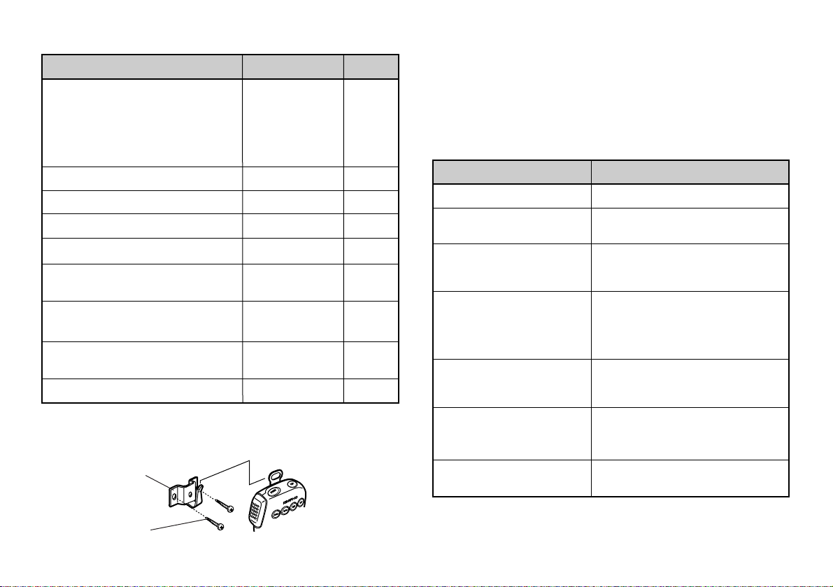
SUPPLIED ACCESSORIES
Accessory
Microphone
U.S.A./ Canada/
General (some): MC-53DM
Europe/
General (some): MC-45
1
DC power cable
Transceiver fuse (15 A)
Mounting bracket
Mounting bracket screws
Microphone hanger
2
(U.S.A./ Canada only)
Microphone hanger screws
(U.S.A./ Canada only)
Warranty card
(U.S.A./ Canada/ Europe only)
Instruction manual
1
The MC-53DM and MC-45 microphones are also sold as
optional accessories {page 83}.
2
Attach the microphone hanger at an appropriate position.
Microphone
hanger
Part Number
1
T91-0568-XX
T91-0396-XX
E30-2111-XX
F51-0017-XX
J29-0632-XX
N99-0331-XX
J19-1526-XX
2
N46-3010-XX
B62-0678-XX
—
Quantity
1
1
1
1
1
1 set
1
2
1
1
CONVENTIONS FOLLOWED IN THIS MANUAL
The writing conventions described below have been
followed to simplify instructions and avoid unnecessary
repetition.
A TTENTION: MOST PROCEDURES REQUIRE THAT YOU PRESS AN
APPROPRIATE KEY IN EACH STEP WITHIN APPROXIMATELY 10
SECONDS, OR THE PREVIOUS MODE WILL BE RESTORED.
What to doInstruction
Press [KEY].
Press
[KEY] (1 s).
Press
[KEY1], [KEY2].
Press
[KEY]+ POWER ON.
Press
[F] (1 s), [KEY].
Press
[F], [KEY] (1 s).
Press
[F] + [KEY].
Press and release KEY.
Press and hold KEY until the
function begins.
Press KEY1 momentarily,
release KEY1, then press
KEY2.
With transceiver power OFF,
press and hold KEY, then turn
ON the transceiver power by
pressing [PWR].
Press and hold [F] for 1
second or longer, then press
KEY.
Press [F] momentarily, release
[F], then press and hold KEY
for 1 second or longer.
Press and hold [F] down, then
press KEY.
Microphone
hanger screw
1
1
K
E
N
W
O
O
D
F
M
D
U
A
L
B
A
N
D
E
R
T
M
-
V
7
PREPARATION FOR MOBILE AND FIXED STATION OPERATION
MOBILE INSTALLATION
2
Install the transceiver in a safe, convenient position inside
3
your vehicle that minimizes danger to your passengers and
4
yourself while the vehicle is in motion. For example,
consider installing the transceiver under the dash in front of
5
the passenger seat so that knees or legs will not strike the
6
radio during sudden braking of your vehicle. Try to pick a
well-ventilated location that is shielded from direct sunlight.
7
■ Installation Example
8
9
10
11
12
13
14
15
16
17
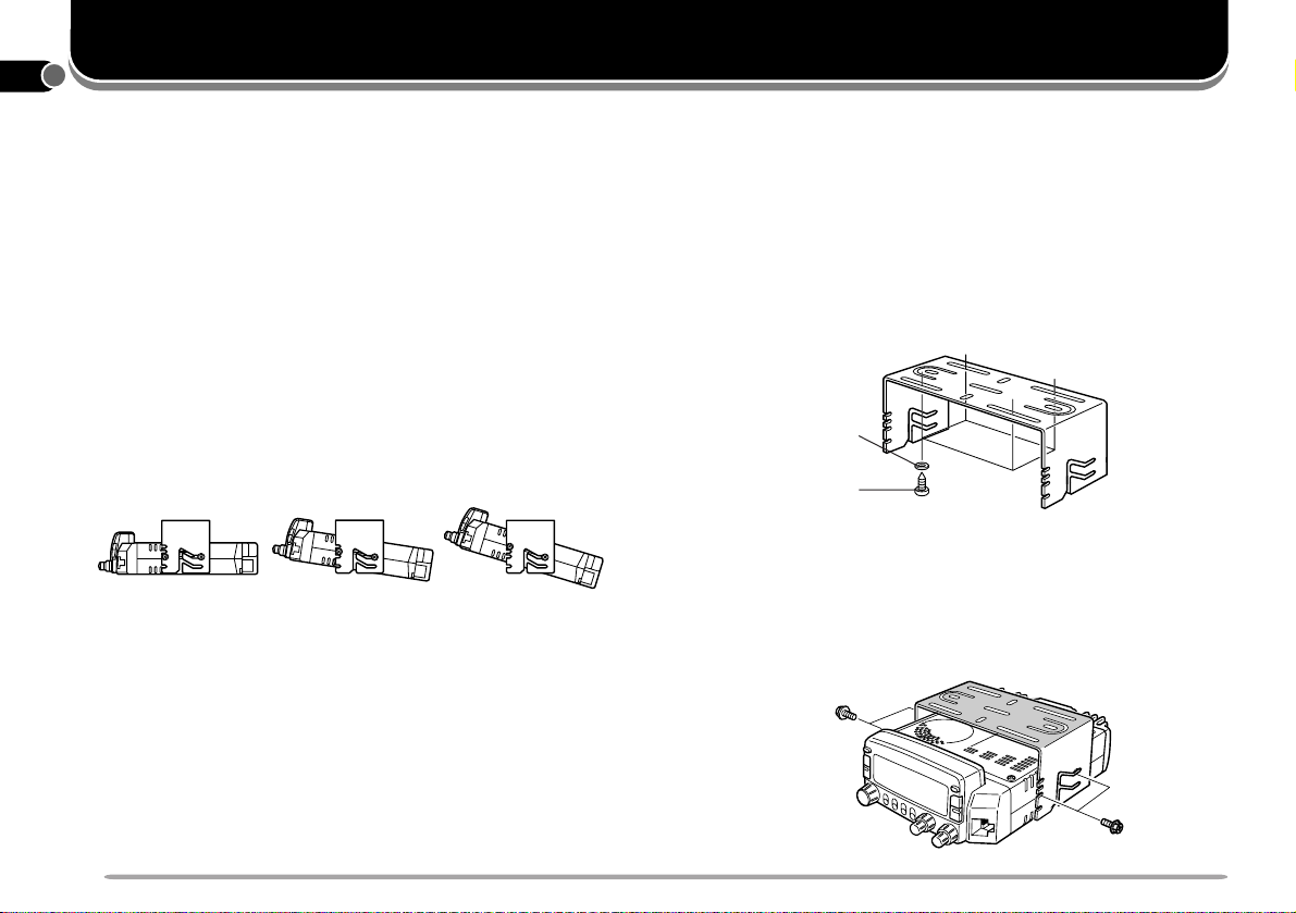
Use the supplied mounting bracket to install the
transceiver inside your vehicle. To enjoy the best
viewing angle, you can position the transceiver in the
bracket in a number of ways as shown below.
M
4
×
8
M
A
M4×8MAX
X
■ Installation Steps
1 Install the mounting bracket in the vehicle using the
supplied flat washers and self-tapping screws.
There are 4 washers and 4 screws supplied.
• The bracket can be mounted with the bracket opening
for the transceiver facing down for underdash
mounting, or with the opening facing up.
• The bracket must be installed so that the 4 screw
holes on the edge of each bracket side are facing
forward.
Flat washer
Self-tapping
screw
M
4
×
8
M
A
X
2 Position the transceiver, then insert and tighten the
supplied hexagon SEMS screws and washers.
There are 2 screws and 2 washers supplied for each
side of the bracket.
• Double check that all hardware is tightened to prevent
vehicle vibration from loosening the bracket or
transceiver .
18
19
20
21
SEMS screw
2
DC POWER CABLE CONNECTION
■ Mobile Operation
The vehicle battery must have a nominal rating of 12 V.
Never connect the transceiver to a 24 V battery. Be
sure to use a 12 V vehicle battery that has sufficient
current capacity . If the current to the transceiver is
insufficient, the display may darken during transmission,
or transmit output power may drop excessively.
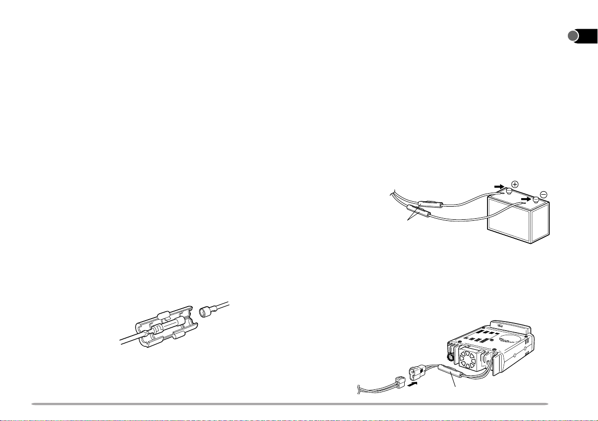
1 Route the DC power cable supplied with the
transceiver directly to the vehicle’s battery terminals
using the shortest path from the transceiver .
• If using a noise filter, it should be installed with an
insulator to prevent it from touching metal on the
vehicle.
• It is not recommended to use the cigarette lighter
socket since some cigarette lighter sockets introduce
an unacceptable voltage drop.
• If the power cable must be routed through a hole in the
vehicle chassis or body, for example in the firewall at
the front of the passenger compartment, use a rubber
grommet to protect the cable from abrasion.
Dismantle the fuse holder to pass the cable through
the firewall.
2 After the cable is in place, wind heat-resistant tape
around the fuse holder to protect it from moisture.
Tie down the full run of cable.
3 To prevent the risk of short circuits, disconnect other
wiring from the negative (–) battery terminal before
connecting the transceiver.
4 Confirm the correct polarity of the connections, and
attach the power cable to the battery terminals; red
connects to the positive (+) terminal, black connects
to the negative (–) terminal.
• Use the full length of the cable without cutting off
excess even if the cable is longer than required. In
particular, never remove the fuse holders from the
cable.
Red
Fuse holder
Black
5 Reconnect any wiring removed from the negative
terminal.
6 Connect the DC power cable to the transceiver’s
power supply connector.
• Press the connectors firmly together until the locking
tab clicks.
1
2
3
4
5
6
7
8
9
10
11
12
13
14
15
16
17
• The entire length of the cable must be dressed so it is
isolated from heat and moisture.
Press
firmly.
Fuse holder
18
19
20
21
3
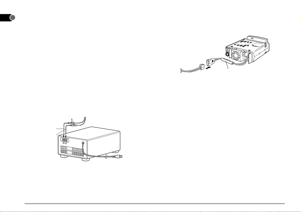
■ Fixed Station Operation
1
2
3
4
5
In order to use this transceiver for fixed station
operation, you will need a separate 13.8 V DC power
supply that must be purchased separately. The
recommended current capacity of your power supply is
12 A.
1 Connect the DC power cable to the regulated DC
power supply and check that polarities are correct
6
7
8
9
10
11
12
13
14
15
16
(Red: positive, Black: negative).
• DO NOT directly connect the transceiver to an
AC outlet!
• Use the supplied DC power cable to connect the
transceiver to a regulated power supply .
• Do not substitute a cable with smaller gauge
wires.
Red (+)
Black (–)
Fuse holder
Regulated DC power
supply
2 Connect the transceiver’s DC power connector to
the connector on the DC power cable.
• Press the connectors firmly together until the locking
tab clicks.
Press
firmly.
Fuse holder
Note:
◆
For your transceiver to fully exhibit its performance capabilities,
the following optional power supply is recommended:
PS-33 (20.5 A, 25% duty cycle).
◆
Before connecting the DC power supply to the transceiver, be
sure to switch the transceiver and the DC power supply OFF .
◆
Do not plug the DC power supply into an AC outlet until you
make all connections.
17
18
19
20
21
T o AC outlet
4
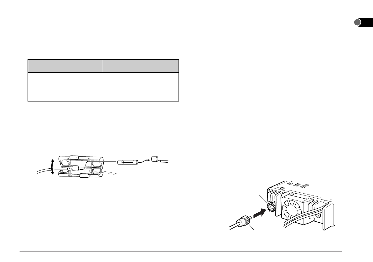
■ Replacing Fuses
If the fuse blows, determine the cause then correct the
problem. After the problem is resolved, then replace the
fuse. If newly installed fuses continue to blow,
disconnect the power cable and contact your dealer or
the nearest Service Center for assistance.
Fuse Location
Transceiver
Supplied Accessory
DC Power Cable
CAUTION: ONL Y USE FUSES OF THE SPECIFIED TYPE AND
RATING.
Note: If you use the transceiver for a long period when the vehicle
battery is not fully charged, or when the engine is OFF, the battery
may become discharged, and will not have sufficient reserves to start
the vehicle. Avoid using the transceiver under these conditions.
Fuse Current Rating
15 A
20 A
ANTENNA CONNECTION
Before operating, you must first install an efficient,
well-tuned antenna. The success of your installation will
depend largely on the type of antenna and its correct
installation. The transceiver can give excellent results if the
antenna system and its installation is given careful
attention.
Your choice of antenna should have a 50 Ω impedance to
match the transceiver input impedance. Use low-loss
coaxial feed line that also has a characteristic impedance of
50 Ω. Coupling the antenna to the transceiver via feed
lines having an impedance other than 50 Ω reduces the
efficiency of the antenna system, and can cause
interference to nearby broadcast television receivers, radio
receivers, and other electronic equipment.
CAUTION:
◆
TRANSMITTING WITHOUT FIRST CONNECTING AN ANTENNA
OR OTHER MATCHED LOAD MAY DAMAGE THE TRANSCEIVER.
ALWAYS CONNECT THE ANTENNA TO THE TRANSCEIVER
BEFORE TRANSMITTING.
◆
ALL FIXED STATIONS SHOULD BE EQUIPPED WITH A
LIGHTNING ARRESTER TO REDUCE THE RISK OF FIRE,
ELECTRIC SHOCK, AND TRANSCEIVER DAMAGE.
Antenna
connector
1
2
3
4
5
6
7
8
9
10
11
12
13
14
15
16
17
To antenna
Feed line connector
18
19
20
21
5
ACCESSORY CONNECTIONS
KENWOOD
FM DUAL BANDER TM-000
KENWOODKENWOOD
FM DUAL FM DUAL
1
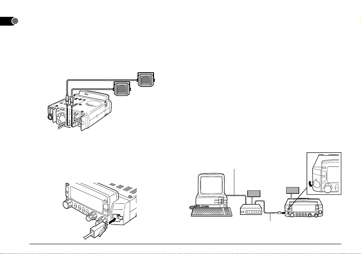
■ External Speakers
2
3
4
5
6
7
8
9
10
11
12
13
14
15
16
17
18
If you plan to use external speakers, choose speakers
with an impedance of 8 Ω. The external speaker jacks
accept a 3.5 mm (1/8") diameter mono (2-conductor)
plug. Recommended speakers include the SP-50B and
SP-41.
■ Microphone
To communicate in the voice modes, plug a 600 Ω
microphone equipped with an 8-pin modular connector
into the modular socket on the front panel of the
transceiver . Press firmly on the plug until the locking tab
clicks.
P ACKET EQUIPMENT CONNECTIONS
If you intend to use this transceiver for Packet operation,
you will need the following equipment.
• Personal computer with communications software
• T erminal Node Controller (TNC)
• TNC power supply
• RS-232C cable
• 6-pin mini DIN plug (optional PG-5A)
For the DATA connector pins, refer to “PACKET
OPERA TION” {page 79}.
Note:
◆
Do not share a single power supply between the transceiver and the
TNC.
◆
Keep as wide a separation between the transceiver and computer as
practical to reduce noise-pickup by the transceiver.
◆
One end of the optional PG-5A cable has not been connectorized.
Attach the appropriate connector that mates with the TNC connector.
RS-232C cable
K
E
N
W
O
O
D
F
M
D
U
A
L
B
A
N
D
E
R
T
M
-
V
7
TNC power
supply
Transceiver
power supply
19
20
21
TNC
TM-V7
PG-5A cable
6
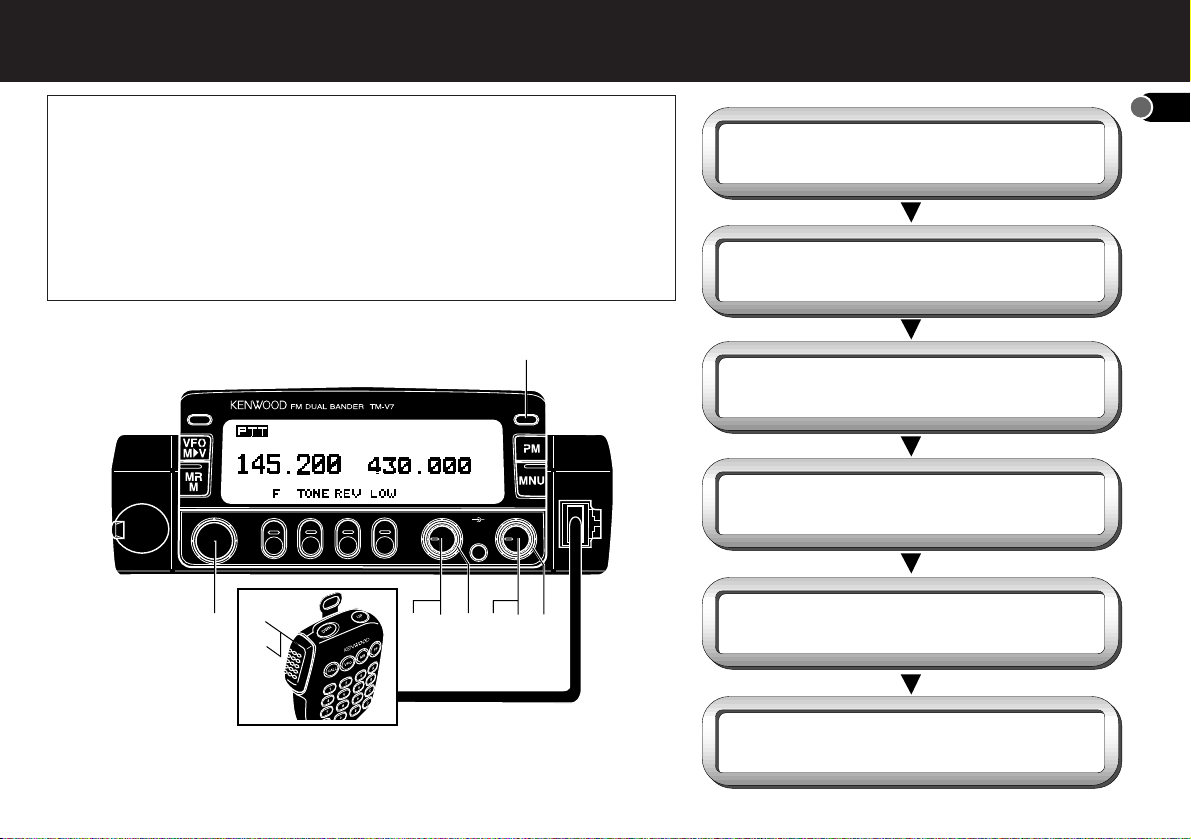
YOUR FIRST QSO
q Switch ON the DC power supply,
then press the PWR switch.
w Turn the VOL and SQL controls to
approximately 9 o'clock.
e Press [BAND SEL] to select the
VHF or UHF band.
r Turn the Tuning control to select
a frequency.
t Press and hold Mic [PTT], then
speak in a normal tone of voice.
y Release Mic [PTT] to receive.
1
If you tend to discard instruction manuals along with the packaging
material .....please don’t. The 6 steps given here will get you on the
air in your first QSO right away. So, you can enjoy the exhilaration
that comes with opening a brand new transceiver .
After trying the rig for a while, settle back in your most comfortable
operating chair with this manual and your favorite drink for an hour or
two. The time spent will be worthwhile.
q
CALL
r
t
y
e
VOL SQL
w
PWR
w
w
ew
2
3
4
5
6
7
8
9
10
11
12
13
14
15
16
17
18
19
MC-53DM
20
21
7
1
BASIC TRANSCEIVER MODES
2
This section introduces you to the basic modes you can
3
select, and differences between the TX band and the
4
Control band.
5
VFO mode
6
Press [VFO] to select. In this mode you can change the
7
operating frequency using the Tuning control or Mic
[UP]/[DWN].
8
9
10
11
CALLCALL
VOL SQL
GETTING ACQUAINTED
Programmable Memory (PM) mode
Press [PM] to select. In this mode you can select the
transceiver environment, by pressing
stored in PM channels {page 36}.
PWRPWR
Menu mode
Press [MNU] to select. In this mode you can change Menu
Nos. using the Tuning control or Mic [UP]/[DWN].
[1]
to
[4]
, that you
CALLCALL
PWRPWR
VOL SQL
12
Memory Recall mode
13
Press [MR] to select. In this mode you can change
14
memory channels, using the T uning control or Mic
15
[UP]/[DWN], where you stored frequencies and related
data. For further information, refer to "MEMORY
16
CHANNELS" {page 28}.
17
18
CALLCALL
19
20
VOL SQL
21
8
CALLCALL
2
PWRPWR
PWRPWR
VOL SQL
TX-Band
Press the left [BAND SEL] (VHF) or the right [BAND SEL]
(UHF) to select. "PTT" on the display shows which band
(VHF or UHF) is currently selected as the transmit (TX)
band. You can use the TX band to transmit signals or to
control the transceiver.
CALLCALL
PWRPWR
VOL SQL
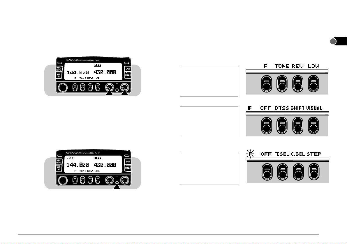
BUTTON FUNCTION DISPLA Y
The lower portion of the display has labels that indicate the
current function of each of the 4 front panel buttons. The
italic font is used to show these 4 buttons in the description
of each operation step. After pressing
pressing
[F]
again or waiting for 10 seconds restores the
basic state.
Basic State
Display Labels
s
[F]
or
[F] (1 s)
,
1
2
3
4
5
6
7
8
Control Band
Press [CONT SEL] to select. On the display "Ctrl" appears
to show which band (VHF or UHF) is currently selected as
the Control band. Use this function when you want to
control the band that is not currently used for TX. After
selecting the Control band, you cannot control the TX
band.
CALLCALL
PWRPWR
VOL SQL
Labels after
Pressing
[F]
s
Labels after
Pressing
Note:
◆
When selecting Program Memory mode, you will also see different
labels. See "Programmable Memory mode" {page 8}.
◆
You can also select different combinations of button labels. Refer to
"CHANGING MULTI-FUNCTION BUTTON LABELS" {page 66}.
◆
After pressing [F] or [F] (1 s), press the appropriate key within
approximately 10 seconds, or the Basic State display will be restored.
[F] (1 s)
s
9
10
11
12
13
14
15
16
17
18
19
20
21
9
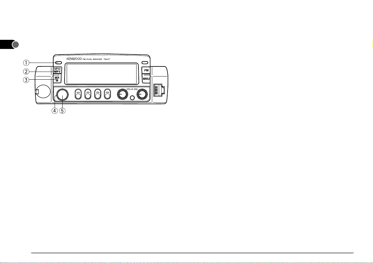
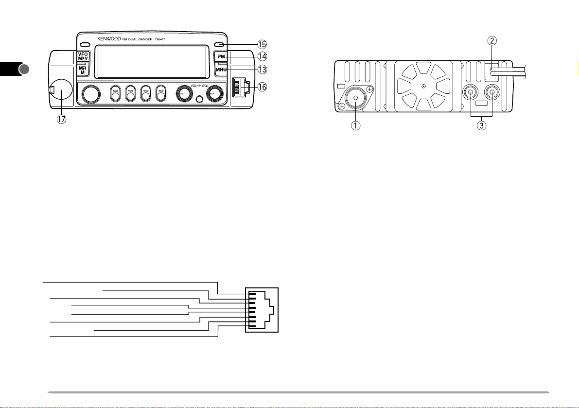
FRONT PANEL
1
Note: This section describes only the main functions of the front panel
2
controls and buttons. For the functions not described here, you will find
explanations in the appropriate sections of this manual.
3
4
5
6
7
8
9
10
qq
q CALL button
qq
11
Recalls the Call channel {page 33}. Also starts or stops
Call/VFO Scan {page 48} when in VFO mode, or
12
Call/Memory Scan {page 48} when in Memory Recall
mode.
13
ww
w VFO button
ww
14
Selects the VFO mode {page 8}. In this mode you can
15
change the operating frequency, using the Tuning control
16
or Mic [UP]/[DWN]. Also provides:
• VFO Scan start/stop to scan the entire VFO range {page 44}.
17
• Program Scan start/stop to scan a programmed range of
18
19
frequencies {page 46}.
CALLCALL
ee
e MR button
ee
Selects the Memory Recall mode {page 31}. In this mode
you can change memory channels, using the Tuning
control or Mic [UP]/[DWN]. Also starts or stops Memory
Scan {page 44}.
rr
r T uning control
rr
PWRPWR
Selects:
• Operating frequencies when in VFO mode.
• Memory channels when in Memory Recall mode {page 31}.
• Menu Nos. when in Menu mode {page 19}.
This control is used for various other selections.
tt
t MHz button
tt
Selects the MHz mode. In this mode you can change the
operating frequency in 1 MHz steps or 10 MHz steps
{page 17}, using the T uning control or Mic [UP]/[DWN].
Also starts or stops MHz Scan {page 47}.
20
21
10
CALLCALL
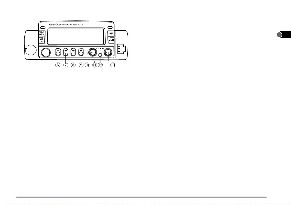
yy
y F (Function) button
yy
PWRPWR
Allows you to select the different functions that are
available using the multifunction buttons.
uu
u TONE button
uu
Switches the Tone function {page 24} or CTCSS function
{page 49} ON or OFF. Also activates or deactivates
Automatic Tone frequency ID {page 49}.
ii
i REV button
ii
Switches the transmit frequency and receive frequency
when operating with a transmit offset or a split memory
channel {page 27}.
oo
o LOW button
oo
Selects High, Mid, or Low transmit output power {page 18}.
!0!0
!0 SQL controls
!0!0
Adjusts the squelch threshold level {page 16}. This allows
you to mute speaker output while no stations are being
received. Turn the left control (VHF) or the right control
(UHF) depending on which band you want to operate.
!1!1
!1 VOL controls/ BAND SEL buttons
!1!1
When turned, these controls adjust the level of receive
audio from the speaker {page 16}. Turn the left control
(VHF) or the right control (UHF) depending on which band
you want to operate.
When pressed, these buttons select the desired TX band.
Press the left button (VHF) or the right button (UHF)
depending on which band you want to select.
!!
!2 CONT SEL button
!!
Selects the band that you can control using the front panel
buttons or the microphone keys.
1
2
3
4
5
6
7
8
9
10
11
12
13
14
15
16
17
18
19
11
20
21
1
2
3
4
5
6
7
!3!3
!3 MNU button
!3!3
8
Selects the Menu mode {page 19}.
9
!4!4
!4 PM button
!4!4
10
Selects the Programmable Memory mode {page 36}.
11
!5!5
!5 PWR switch
!5!5
12
Switches the transceiver ON or OFF {page 16}.
13
!!
!6 Microphone connector
!!
14
Insert the 8-pin modular connector plug until the locking tab
"clicks".
15
UP
DC 8 V, 200 mA max.
16
GND
STBY (PTT)
17
GND (MIC)
MIC
18
NC: No connection
DWN
19
!7!7
!7 DATA connector
!7!7
20
CALLCALL
Connect a Terminal Node Controller (TNC) for Packet
21
operation. Accepts a 6-pin mini DIN plug {page 6}.
12
REAR PANEL
PWRPWR
qq
q Antenna connector
qq
Connect an external antenna {page 5}. When making test
transmissions, connect a dummy load in place of the
antenna. The antenna system or load should have an
impedance of 50 Ω. The TM-V7E accepts a male N-type
connector and other versions accept a male PL-259
connector. This transceiver has only one antenna
connector because of a built-in duplexer .
ww
w Power Input 13.8 V DC cable
ww
Connect to a 13.8 V DC power source. Use the supplied
DC power cable {pages 3 and 4}.
ee
e Speaker jacks
ee
If you wish, connect an optional external speaker for clearer
audio. These jacks accept a 3.5 mm (1/8") diameter ,
2-conductor plug. See page 6 for more information.
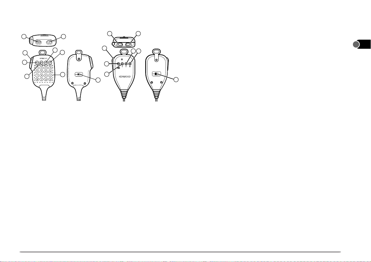
MICROPHONE
MC-53DM MC-45
12
7
3
5
6
qq
q UP button
qq
ww
w DWN button
ww
8
6
Raises or lowers the operating frequency , the memory
channel number, the menu number, etc. Holding either
button down causes the action to be repeated. Also,
switches between values for functions with multiple
choices.
ee
e PTT (Push-to-talk) switch
ee
Press to transmit; release to receive. Also used to cancel
various functions such as Scan {page 40} or Automatic
Band Change {page 62}.
rr
r LOCK switch
rr
Locks all microphone keys except [PTT] and the DTMF
keypad, if equipped.
2 1
3
5
6
4
DWN UP
MIC
VFO MR PFCALL
7
8
LOCK
ELECTRET CONDENSER MIC
MADE IN JAPAN
tt
t CALL key
tt
yy
y VFO key
yy
uu
u MR key
uu
Identical to the front panel CALL, VFO, and MR buttons.
These keys can be re-programmed, if desired {page 72}.
ii
i PF key
ii
Depending on which function you select by accessing
"PF1" in Menu No. 16 {page 21}, the function of this key
4
differs. Refer to "CONFIGURING PROGRAM FUNCTION
KEYS" {page 72}.
oo
o DTMF keypad (MC-53DM only)
oo
The 16-key keypad is used for DTMF functions, or to
directly enter a frequency or a memory channel number .
1
2
3
4
5
6
7
8
9
10
11
12
13
14
15
16
17
18
19
20
13
21
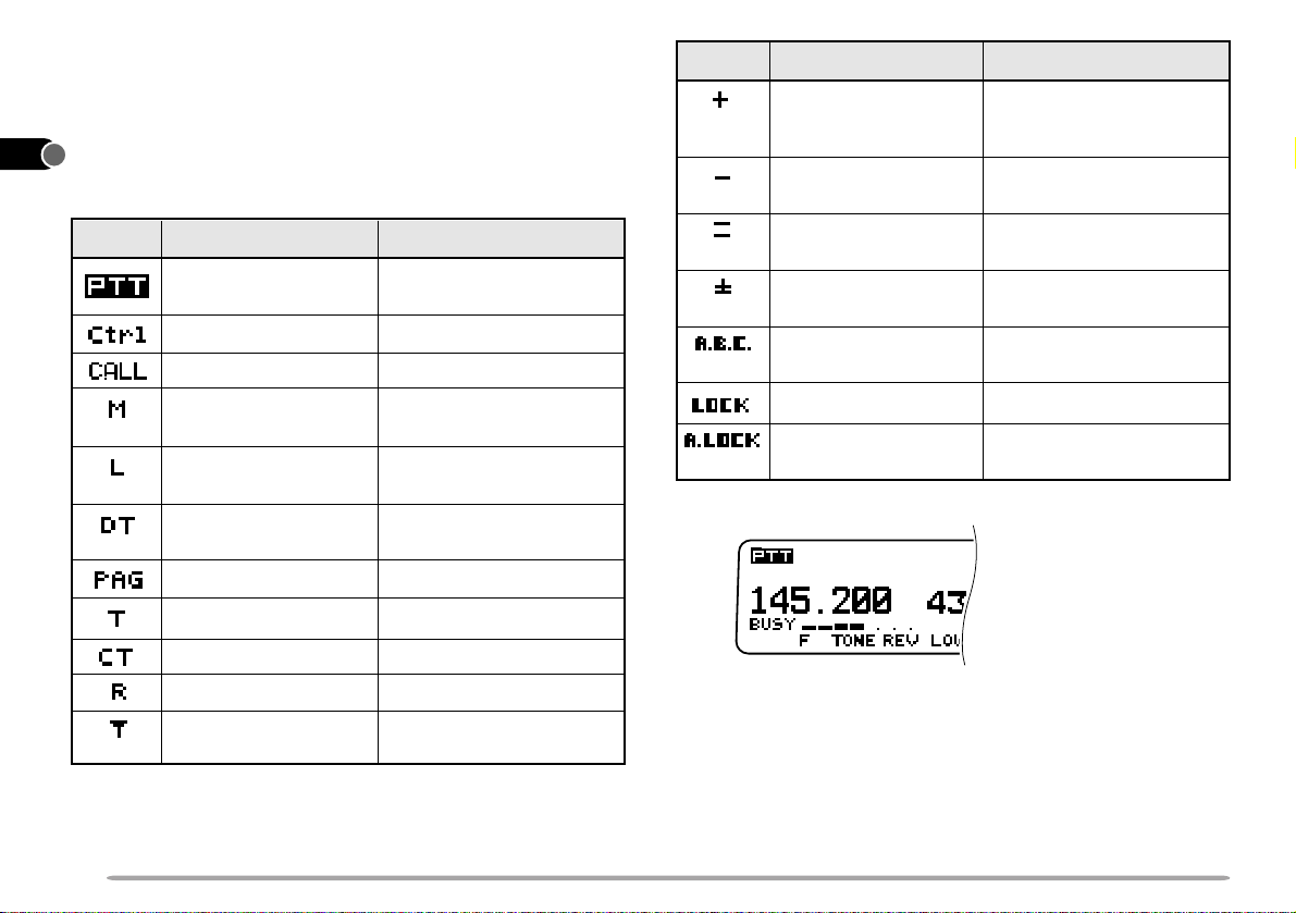
INDICATORS
1
On the display you will see various indicators that show
2
what you have selected. Sometimes you may not recall
what those indicators mean or how you can cancel the
3
current setting. In such a case, you will find this table very
useful.
4
10
11
12
13
14
15
16
17
18
19
5
Indicator
6
7
8
9
What You Selected
TX (Transmit) band
Control band
Call channel
Medium transmit
power
Low transmit power
DTSS
Page
Tone function
CTCSS
Reverse
Automatic Simplex
Checker (ASC)
What You Press to Cancel
Always visible on either
band
[CONT SEL]
[CALL]
[LOW], [LOW]
the default (High)
[LOW]
to select the
default (High)
[F], [DTSS], [F],
[DTSS]
[F], [DTSS]
[TONE], [TONE]
[TONE]
[REV]
[REV]
to select
What You Press to Cancel
[F], [SHIFT], [F]
[SHIFT]
more
[F], [SHIFT]
one more
( TM-V7E: one
[F], [SHIFT]
(TM-V7E:
[F], [SHIFT]
[F], [SHIFT]
[VFO]
(TM-V7E)
What You SelectedIndicator
Plus offset direction
Minus offset direction
Minus offset direction
(–7.6 MHz)
Split memory
channel
Automatic Band
[F]
, [MNU]
Change (A.B.C.)
[F],
[MHz]
[F]
, [MHz]
Transceiver Lock
All Lock
[MHz]+ POWER ON
then
When you receive a signal:
• "BUSY" appears when the squelch {page 16} is open.
• The S-meter shows the strength of received signals.
,
)
)
20
21
14
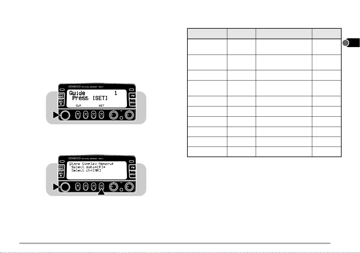
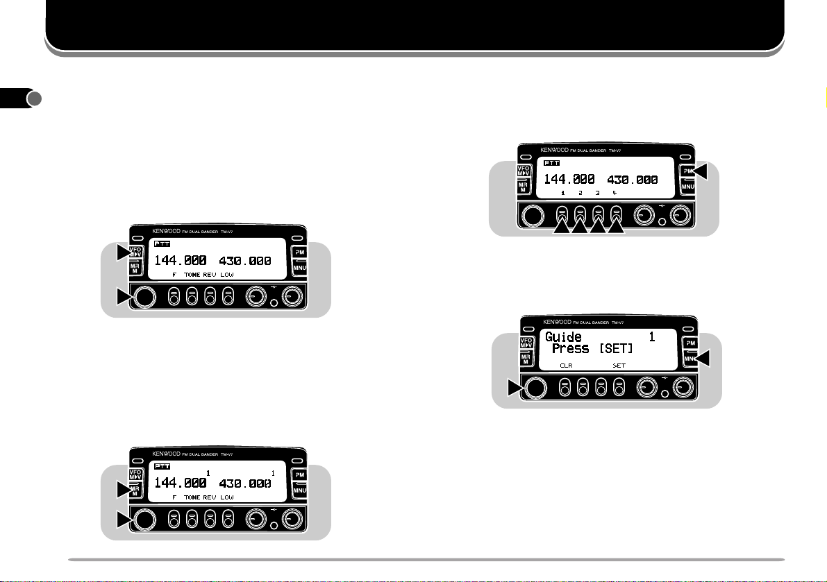
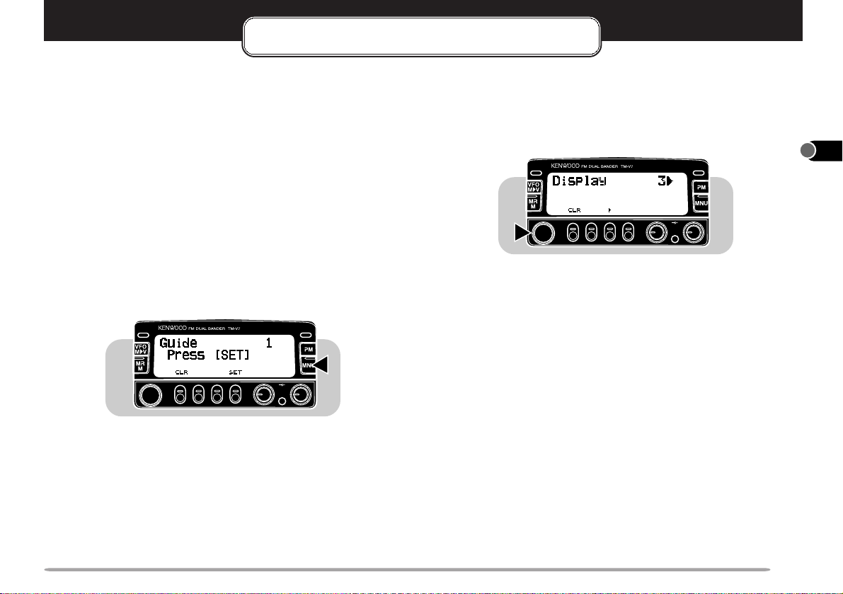
TRANSCEIVER GUIDE
When you cannot recall how to use a function and you do
not have this manual with you, you need not worry. This
transceiver shows you the steps for operating the functions
that you will often use.
Note: Not all functions are supported by Transceiver Guide.
1 Press [MNU] to enter Menu mode.
2 Select Menu No. 1 (Guide).
CALLCALL
3 Press
[SET]
, then turn the Tuning control to select the
desired function.
• Y ou can also press Mic [UP]/[DWN] to select a function.
CALLCALL
PWRPWR
VOL SQL
PWRPWR
The following table lists the function indexes that you will
see on the display.
Function Index
VFO Scan
Ref. Page
44
Function Index
Transmit Stored
Ref. Page
60
DTMF
MHz Scan
47
Store Simplex
30
Memory
Memory Scan
Call Scan
44
48
Store Split Memory
Store Simplex Call
30
33
Ch
MR Ch Clr
Ch Disp
All Reset
VFO Reset
PM Reset
Repeater
1
U.S.A./ Canada only
1
31
34
35
35
39
81
Store Split Call Ch
Assign PF1 key
Assign PF2 key
Assign PF3 key
Assign PF4 key
34
72
72
72
72
1
2
3
4
5
6
7
8
9
10
11
12
13
14
15
2
VOL SQL
1
4 To exit Guide mode, press [MNU] again.
16
17
18
19
20
21
15
1
SWITCHING POWER ON/OFF
2
1 Switch ON the DC power supply.
3
4
5
6
7
8
• If operating mobile, skip this step.
2 Press the PWR switch to switch ON the transceiver.
CALLCALL
VOL SQL
OPERATING BASICS
PWRPWR
ADJUSTING SQUELCH
The purpose of squelch is to silence audio output from the
speaker when no signals are present. When squelch is set
correctly, you will hear sound only while a station is actually
being received. The point at which ambient noise on a
frequency just disappears, called the squelch threshold,
depends on the frequency.
Turn the SQL control clockwise to just eliminate the
background noise when no signal is present.
9
3 To switch OFF the transceiver , press the PWR switch
10
11
12
again.
• In a fixed installation, after the transceiver has been
switched ON, it can then be switched OFF or ON by using
only the power switch on the DC power supply.
13
14
ADJUSTING VOLUME
15
Turn the VOL control clockwise to increase the audio level
and counterclockwise to decrease the audio level.
16
17
18
19
CALLCALL
PWRPWR
VOL SQL
20
21
16
CALLCALL
PWRPWR
VOL SQL
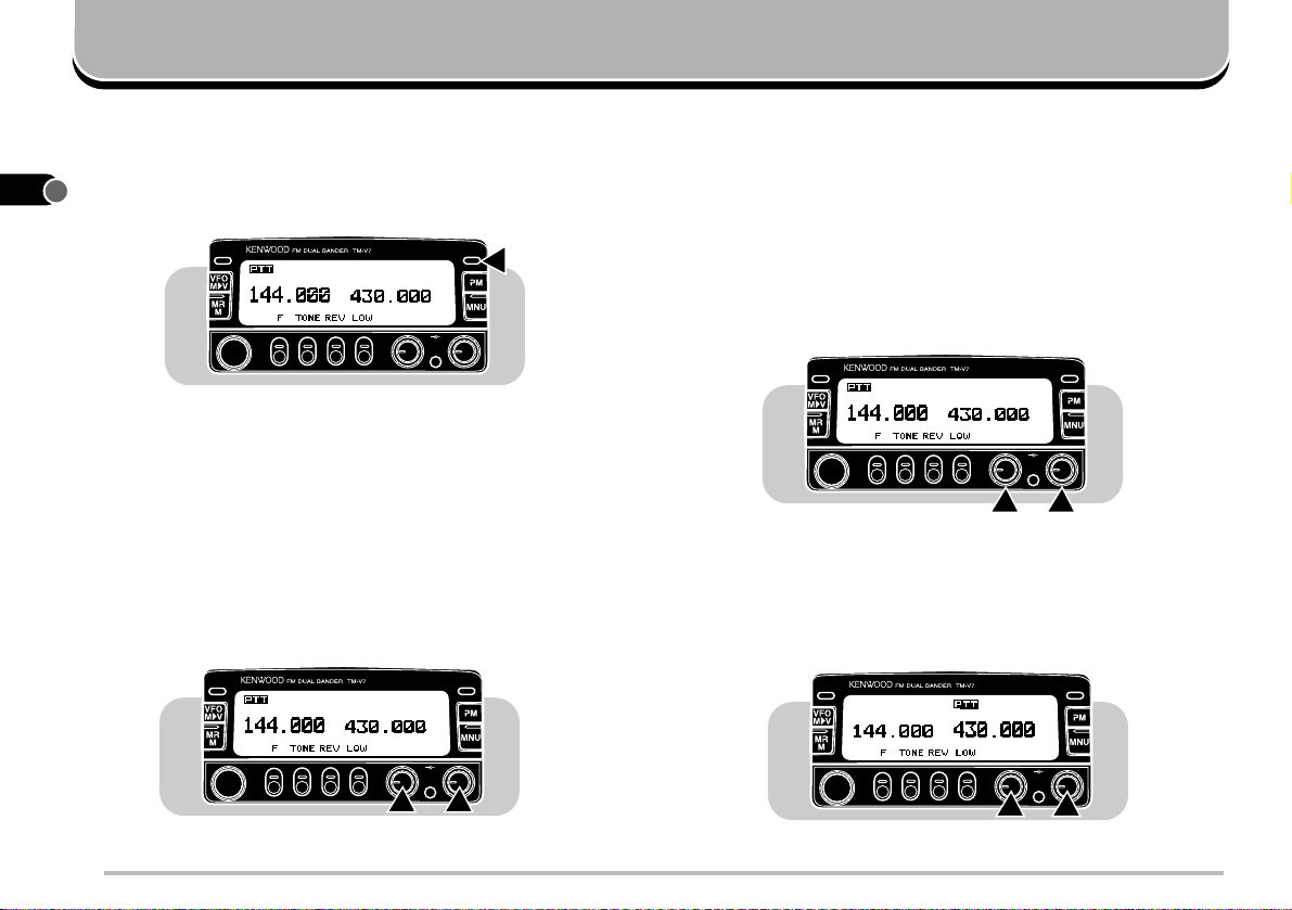
SELECTING A BAND
Press [BAND SEL] to select the VHF or UHF band.
• "PTT" appears above the VHF or UHF frequency to show
which band you selected.
CALLCALL
PWRPWR
VOL SQL
SELECTING FREQUENCIES
■ Tuning Control
Using the Tuning control is convenient when you are
within easy reach of the transceiver front panel, and the
frequencies to be selected lie near the current
frequency.
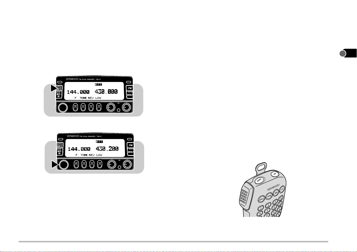
1 Press [VFO] to select VFO mode.
CALLCALL
2 Turn the Tuning control to select a receive
frequency.
CALLCALL
2
• Clockwise rotation increases the frequency one
frequency step at a time.
• Counterclockwise rotation decreases the frequency
one step at a time.
• To change frequencies in steps of 1 MHz, press [MHz]
first. Pressing [MHz] again cancels the 1 MHz
function. To change in steps of 10 MHz, press
[F]
+ [MHz] first. Pressing
function; pressing [MHz] starts the 1 MHz function.
[F]
PWRPWR
VOL SQL
PWRPWR
VOL SQL
cancels the 10 MHz
• If you cannot select a particular receive frequency, the
frequency step size needs to be changed. See
"CHANGING FREQUENCY STEP SIZE" {page 65} for
further information.
• Y ou can also select frequencies via the microphone
keypad (MC-53DM only). See "KEYPAD DIRECT
ENTRY" {page 74}.
■ Microphone [UP]/[DWN] Buttons
Using Mic [UP]/[DWN] for frequency selection is useful
when mobiling or any time you are not immediately in
front of the transceiver.
Press [UP] or [DWN] once to change the receive
frequency by one frequency step in the direction
indicated by the button.
• Pressing and holding either button causes the frequency
to step repeatedly in one direction until the button is
released.
• To change frequencies in steps of 1 MHz (or 10 MHz),
press [MHz] (or
[F]
+ [MHz]) first.
MC-53DM
1
2
3
4
5
6
7
8
9
10
11
12
13
14
15
16
17
18
19
20
21
17
(No Indicator)
Medium
Low
("M")
("L")
High
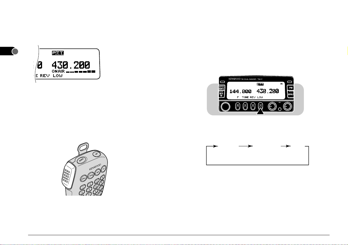
TRANSMITTING
1
1 When ready to begin transmitting, press and hold Mic
2
3
4
5
6
[PTT] and speak in a normal tone of voice.
• "ON AIR" and the RF power meter appear.
■ Selecting Output Power
It’s wise, and required by law, to select the lowest power
that allows reliable communication. If operating from
battery power, lower transmit power will give you more
operating time before a charge is necessary. Reducing
power lowers the risk of interfering with others on the
band.
Press
[LOW]
to select the transmit power you require.
7
8
9
10
11
• Speaking too close to the microphone, or too loudly, may
increase distortion and reduce intelligibility of your signal
at the receiving station.
• The RF power meter shows the relative transmit output
power.
2 When you finish speaking, release Mic [PTT].
12
13
14
15
16
17
18
MC-53DM
19
20
21
18
CALLCALL
• Each time you press
[LOW]
, the transmit power is
PWRPWR
VOL SQL
changed as shown below.
CAUTION:
◆
DO NOT TRANSMIT WITH HIGH OUTPUT POWER FOR
EXTENDED PERIODS. THE TRANSCEIVER MAY OVERHEAT
AND MALFUNCTION.
◆
CONTINUOUS TRANSMISSIONS CAUSE THE RADIA TOR T O
OVERHEAT. NEVER TOUCH THE RADIATOR IN SUCH A
SITUA TION.
Note: When the transceiver overheats because of ambient high
temperature or continuous transmissions, the protective circuit may
function to lower transmit output power.
MENU SET-UP
WHAT IS A MENU?
Many functions on this transceiver are selected or
configured via a software-controlled Menu instead of
physical controls on the transceiver. Once familiar with the
Menu system, you will appreciate the versatility it offers.
MENU ACCESS
1 Select the desired band.
• For some Menu Nos., you can select a different setting on
each band.
2 Press [MNU] to enter Menu mode.
• The last Menu No. used appears.
CALLCALL
PWRPWR
VOL SQL
3 Turn the Tuning control, or press Mic [UP]/[DWN], to
select the Menu No.
• "CLR" and either "s" or "SET" appear as button labels.
• To cancel the selection and restore the previous display,
[CLR]
press
.
CALLCALL
PWRPWR
VOL SQL
The subsequent steps differ depending on which Menu No.
you selected. See the appropriate sections in this manual.
Note:
◆
As required, operate keys or the Tuning control in each step within
approximately 10 seconds, or the previous mode will be restored.
◆
After selecting for an Item No. under a Menu No., pressing [
the setting and allows you to select for another Item No.
tt
t
] stores
tt
1
2
3
4
5
6
7
8
9
10
11
12
13
14
15
16
19
17
18
19
20
21

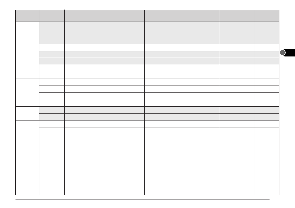
MENU CONFIGURATION
1
Note: For the shaded Menu functions, select the appropriate band (VHF or UHF) before entering Menu mode.
2
3
Menu No. Item No. Ref. Page
Description
Selections
Default
10
11
12
13
14
15
16
17
18
19
20
21
4
5
6
7
8
9
1
2
3
––
1
2
3
1
2
3
Transceiver Guide
Number of Channels for Visual
Scan
Power-ON Message
Multi-function Button Label
Display Reverse
Display Contrast
Display Dimmer
See reference page
25/ 49/ 73/ 147
See reference page
See reference page
Positive/ negative
Level 1 (min.) ~ level 16 (max.)
Level 1 (max.) ~ level 4 (min.)/
49
"KENWOOD"
F/TONE/REV/LOW
Negative
8
1
15
41
69
66
71
71
70
OFF
4
4
1
2
Auto Dimmer Change
Memory Channel Lockout
VHF/UHF Memory Channel Ratio
ON/ OFF
ON/ OFF
90:90/ 110:70/ 130:50/ 50:130/
OFF
OFF
90:90
70
45
29
70:110/ 140:140
3
4
5
1
Memory Channel Name
Auto PM Channel Storing
Automatic Repeater Offset
See reference page
ON/ OFF
ON/ OFF
OFF
ON
32
39
26
(U.S.A./ Canada/ Europe only)
2
3
Offset Frequency
1750 Hz Tone Transmit Hold
00.00 MHz ~ 29.95 MHz in
steps of 50 kHz
ON/ OFF
See reference
page
OFF
24
73
(TM-V7E only)
20
Menu No. Item No.
6
7
8
9
10
11
12
––
––
––
––
––
––
1
2
3
13
1
2
14
1
2
3
15
1
2
16
1
2 ~ 5
6
17
––
Description Selections
Programmable VFO (Upper/ lower
limits)
DTMF Number Storing
Scan Resume Methods
Advanced Intercept Point (AIP)
Automatic Power Off (APO)
Time-Out T imer (TOT)
DTSS/ Page Code Transmit Delay
Auto Page Cancel
Page Answer Back
Frequencies selectable on the
band
See reference page
Time-Operated/ Carrier-Operated
ON/ OFF
ON/ OFF
3/ 5/ 10 minutes
350 ms/ 550 ms
Auto (ON)/ manual (OFF)
ON/ OFF
(U.S.A./ Canada only)
S-meter Squelch
S-meter Squelch Hang T ime
Beep Volume
Speaker Configuration
Voice Synthesizer
ON/ OFF
125 ms/ 250 ms/ 500 ms/ OFF
Level 1 (min.) ~ 7 (max.) / OFF
Mode 1/ mode 2
English/ Japanese/ OFF
(Only when the optional VS-3 is installed.)
Data Transfer Rate
Data TX/RX Band
Microphone Control
Programmable Function Keys
DTMF Monitor
Repeater TX Hold
1200 bps/ 9600 bps
ON/ OFF
ON/ OFF
See reference page
ON/ OFF
ON/ OFF
(U.S.A./ Canada only)
Default Ref. Page
Upper/lower RX
frequency limits
on the band
Time-Operated
OFF
OFF
10 minutes
350 ms
Manual
OFF
OFF
OFF
Level 5
Mode 1
English
1200 bps
OFF
OFF
OFF
ON
64
59
43
62
61
61
52,56
57
57
68
68
66
76
82
79
79
77
73
58
81
1
2
3
4
5
6
7
8
9
10
11
12
13
14
15
16
17
18
19
20
21
21
1
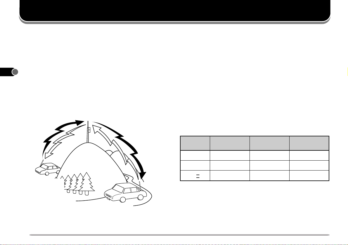
OPERATING THROUGH REPEATERS
Compared to simplex communication, you can usually
2
transmit over much greater distances by using a repeater.
3
Repeaters are typically located on a mountain top or other
elevated location. Often they operate at higher ERP
4
(Effective Radiated Power) than a typical station. This
combination of elevation and high ERP allows
5
communications over considerable distances.
6
Repeaters are often installed and maintained by radio
7
clubs, sometimes with the cooperation of local businesses
involved in the communications industry. During
8
emergencies, repeater networks can be a valuable aid to
officials responsible for coordinating communications in a
9
community.
10
11
12
13
14
15
16
17
18
TX: 144.73 MHz
TX tone: 88.5 Hz
RX: 145.33 MHz
REPEATER ACCESS
Most Amateur Radio voice repeaters use a separate
receive and transmit frequency . The transmit frequency
may be higher or lower than the receive frequency but the
difference in frequencies will be a standard amount, or
"standard split". You can set a separate receive and
transmit frequency by selecting the offset frequency and
offset direction with respect to the receive frequency.
In addition, some repeaters may require the transceiver to
transmit a tone before the repeater can be used. To
transmit this required tone, activate the Tone function and
select a tone frequency. The required tone frequency
depends on the repeater you are accessing.
Most repeater configurations fall into one of the following
categories:
Offset
TM-V7A/ E
Direction
+
–
+600 kHz
–600 kHz
– (" ")
N/A: Not applicable
VHF
N/A
TM-V7A
UHF
+5 MHz
–5 MHz
N/A
TM-V7E
UHF
+1.6 MHz
–1.6 MHz
–7.6 MHz
19
20
21
TX: 144.73 MHz
TX tone: 88.5 Hz
RX: 145.33 MHz
22
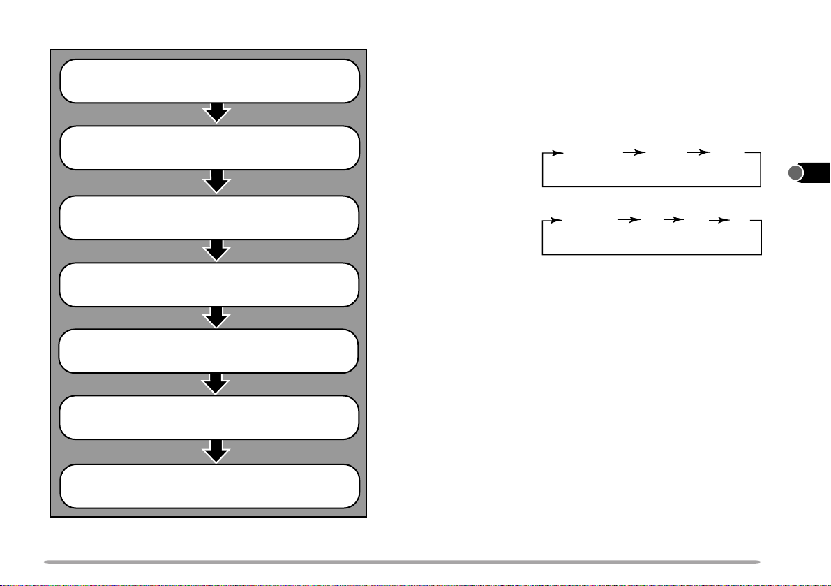
Flow Chart for Repeater Access
Simplex
+
−
−
−
Select a band.
Select a receive frequency.
Select an offset direction.
■ Selecting Offset Direction
Select whether the transmit frequency will be higher (+)
or lower (–) than the receive frequency.
Press
[F], [SHIFT]
• Each time you repeat this key operation, the offset direction
changes as shown below.
TM-V7A/E
(VHF)
TM-V7A
(UHF)
TM-V7E
(UHF)
.
Simplex
+
−
1
2
3
4
5
6
7
8
9
Select an offset frequency.
Activate the Tone function, if necessary.
Select a tone frequency, if necessary.
Press Mic [PTT].
If the offset transmit frequency falls outside the allowable
transmit frequency range, transmitting is inhibited until
the transmit frequency is brought within the band limits
by one of the following methods:
• Move the receive frequency further inside the band.
• Change the offset direction.
Note: While using a split memory channel or transmitting, you cannot
change the offset direction.
23
10
11
12
13
14
15
16
17
18
19
20
21
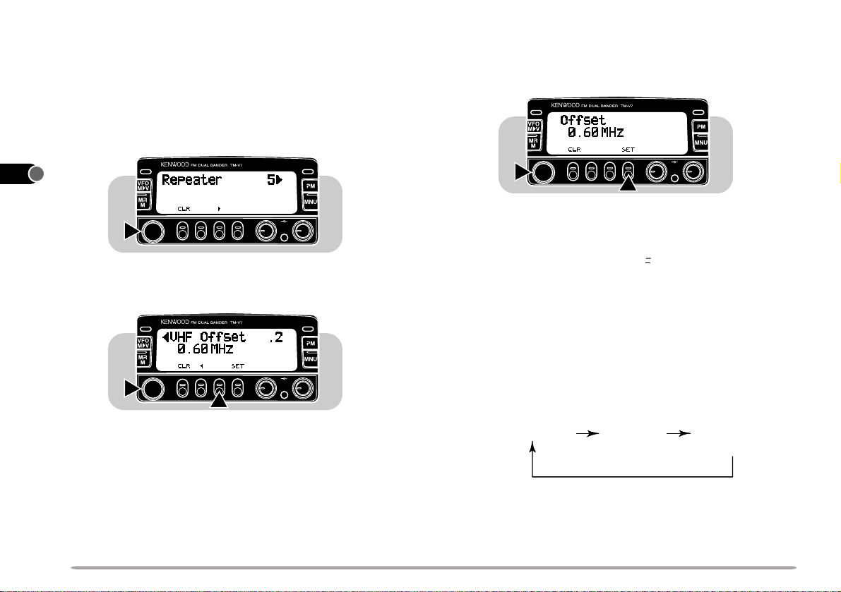
■ Selecting Offset Frequency
No Indicator
Tone
CTCSS
("T")
("CT")
1
2
3
4
5
6
7
8
9
10
11
12
13
14
15
16
Select how much the transmit frequency will be offset
from the receive frequency.
1 Select the desired band.
2 Press [MNU] to enter Menu mode.
3 Select Menu No. 5 (Repeater).
CALLCALL
2
4 Press
ss
[
s
]
, then select Item No. 2 (VHF Offset or
ss
UHF Offset).
• The current offset frequency appears.
CALLCALL
2
5 Press
[SET]
, then select the appropriate offset
frequency.
• The selectable range is from 00.00 MHz to 29.95 MHz
in steps of 50 kHz.
VOL SQL
CALLCALL
PWRPWR
6 Press
2
[SET]
again to complete the setting.
1
PWRPWR
VOL SQL
7 Press [MNU] again to exit Menu mode.
TM-7VE only: If you have selected " " for the offset direction, you
cannot change the default (7.6 MHz).
Note: After changing the offset frequency , the new offset frequency
will also be used by Automatic Repeater Offset.
PWRPWR
■ Activating Tone Function
Press
VOL SQL
1
[TONE]
• Each time you press
shown below.
to activate the Tone function.
[TONE]
, the selection changes as
17
18
19
20
21
24

■ Selecting a Tone Frequency
1 Press
2 Press
3 Turn the Tuning control, or Mic [UP]/[DWN] to select
4 Press
[TONE]
[F] (1 s), [T .SEL]
• The current tone frequency appears.
to activate the Tone function.
.
CALLCALL
VOL SQL
21
a tone frequency.
[OFF]
to complete the setting.
PWRPWR
Freq.
No.
(Hz)
01
67.0
02
71.9
03
74.4
04
77.0
05
79.7
06
82.5
07
85.4
08
88.5
09
91.5
10
94.8
Note: Use Nos. 01 to 38 shown in the table above when selecting
tone frequencies via Keypad Direct Entry {page 75}.
TM-V7E only: To transmit a 1750 Hz tone, assign the 1750 Hz
Tone function to one of the Programmable Function keys of the
microphone {page 72}.
No.
11
12
13
14
15
16
17
18
19
20
Freq.
(Hz)
97.4
100.0
103.5
107.2
110.9
114.8
118.8
123.0
127.3
131.8
No.
21
22
23
24
25
26
27
28
29
30
Freq.
(Hz)
136.5
141.3
146.2
151.4
156.7
162.2
167.9
173.8
179.9
186.2
No.
31
32
33
34
35
36
37
38
Freq.
(Hz)
192.8
203.5
210.7
218.1
225.7
233.6
241.8
250.3
1
2
3
4
5
6
7
8
9
10
11
12
13
14
15
16
25
17
18
19
20
21

■ Automatic Repeater Offset
1
2
3
4
5
6
7
8
9
10
11
12
13
14
15
16
17
18
(U.S.A./ Canada/ Europe Only)
This function automatically selects an appropriate offset
direction according to the frequency that you select on
the VHF band. The transceiver is programmed for
offset direction as shown below. To obtain an up-to-date
band plan for repeater offset direction, contact your
national Amateur Radio association.
U.S.A. and Canada versions
This complies with the standard ARRL band plan.
144.0 145.5 146.4 147.0 147.6
145.1 146.0 146.6 147.4 148.0 MHz
S: Simplex
European versions
144.0 145.6 145.8 146.0 MHz
S
S: Simplex
Note: Automatic Repeater Offset does not function when Reverse
or CTCSS is ON. However, pressing [REV] after Automatic Repeater
Offset has selected an offset (split) status, exchanges the receive
and transmit frequencies.
1 Select the VHF band.
2 Press [MNU] to enter Menu mode.
3 Select Menu No. 5 (Repeater).
CALLCALL
2
4 Press
−−
+
SS
S
+
−
S
5 Press
ss
[
s
]
, then select Item No. 1 (Auto Offset).
ss
CALLCALL
2
[SET]
to toggle the function ON (default) or
1
PWRPWR
VOL SQL
PWRPWR
VOL SQL
OFF.
–
S
6 Press [MNU] again to exit Menu mode.
19
20
21
26

REVERSE FUNCTION
When used while monitoring a repeater, the Reverse
function allows you to manually check the signal strength of
a station accessing the repeater. If the station’ s signal is
strong, it is best to move to a simplex frequency to continue
the contact and free up the repeater.
Press
[REV]
to toggle the Reverse function ON or OFF.
• The receive frequency and the transmit frequency are
exchanged.
• "R" appears when the function is ON.
■ Automatic Simplex Checker (ASC)
This function automatically monitors the strength of the
signal you are receiving from the repeater . If the signal
strength is high enough to allow direct contact without a
repeater, an indicator on the display begins blinking.
This alerts you to move off to a private frequency and
release the repeater for other users.
1 Press
[REV] (1 s)
to switch the function ON.
• The ASC indicator appears.
1
2
3
4
5
6
7
8
9
10
Note:
◆
If pressing [REV] places the transmit frequency outside the allowable
transmit frequency range, an error beep sounds when [PTT] is
pressed, and transmission is inhibited.
◆
If reversal would place the receive frequency outside the receive
frequency range, an error beep sounds when [REV] is pressed. No
reversal occurs.
◆
Automatic Repeater Offset does not function while Reverse is ON.
◆
You cannot switch Reverse ON or OFF while transmitting.
• While direct contact is possible, the ASC indicator
blinks.
2 To cancel ASC, press
Note:
◆
When direct contact becomes impossible, the ASC indicator
stops blinking.
◆
ASC does not function if your transmit and receive frequencies
are the same (simplex operation).
◆
ASC does not function while scanning.
◆
If you recall a memory channel or the Call channel that contains
Reverse ON status, ASC is switched OFF.
[REV]
.
11
12
13
14
15
16
17
18
19
20
21
27

1
In memory channels, you can store frequencies and related
2
data that you often use. A total of 280 memory channels
are available, 140 each for VHF and UHF.
3
You can also store a name for each memory channel.
4
Using this naming function restricts the total number of
5
memory channels to 180, but allows you to select the ratio
of channels between the VHF and UHF bands, from among
6
5 types. For more information, see "NAMING MEMORY
CHANNELS" {page 32}.
7
8
SIMPLEX OR SPLIT MEMORY CHANNEL?
9
There are 2 methods of storing transmit/receive
10
frequencies and related data in memory channels,
11
depending on the relationship of the transmit and receive
frequencies. You can use each memory channel either as a
12
simplex channel or split channel. Use as a split channel to
store a separate receive and transmit frequency .
13
• Simplex memory channels:
14
15
16
17
18
RX frequency = TX frequency
• Split memory channels:
RX frequency ≠ TX frequency
Note: Not only can you store data in memory channels, but you can also
overwrite existing data with new data.
MEMORY CHANNELS
The data listed below can be stored in each memory
channel:
RX frequency
TX frequency
Tone frequency
CTCSS frequency
Tone or CTCSS status
Frequency step
Offset direction
Reverse status
DTSS code, DTSS status
Memory channel lockout
Memory channel name
Yes: Can be stored in memory.
N/A: Not applicable
Parameter
Simplex
Channel
Yes
Yes
Yes
Yes
Yes
Yes
Yes
Yes
Yes
Yes
Split
Channel
Yes
Yes
Yes
Yes
Yes
Yes
N/A
N/A
Yes
Yes
Yes
19
20
21
28

VHF/UHF MEMORY CHANNEL RATIO
You can change the ratio of memory channels between the
VHF and UHF bands, from the factory default (90 channels
each). Changing the ratio requires all memory channels to
be cleared. So decide the appropriate ratio before storing
data in memory channels.
The selectable ratios are as shown below:
VHF Band
90
110
130
50
70
140
UHF Band
90
70
50
130
110
140
Yes: Memory channel name programmable
N/A: Not applicable
1 Press [MNU] to enter Menu mode.
2 Select Menu No. 4 (Memory).
Memory Channel
Name
Yes
Yes
Yes
Yes
Yes
N/A
3 Press
4 Press
5 Press
ss
[
s
]
, then select item No. 2 (Channel Ratio).
ss
CALLCALL
2
[SET]
, then select the desired ratio.
CALLCALL
2
[SET]
again.
1
1
PWRPWR
VOL SQL
PWRPWR
VOL SQL
• A confirmation message appears.
[CLR]
• To quit changing the ratio, press
6 Press
[SET]
once again.
.
• The memory channels are cleared and the ratio is changed.
• The previous mode is restored.
1
2
3
4
5
6
7
8
9
10
11
12
13
14
15
16
CALLCALL
PWRPWR
17
18
2
VOL SQL
19
20
21
29

STORING DATA IN SIMPLEX CHANNELS
1
1 Select the desired band.
2
2 Select the desired frequency and related data (T one,
3
4
5
6
7
8
CTCSS, DTSS, etc.) using VFO mode, Memory Recall
{page 31}, or the Call channel {page 33}.
3 Press
[F]
.
• A memory channel number and an arrow appear.
• The arrow shows whether the current memory channel
contains data ("
ss
s") or not ("
ss
uu
u").
uu
STORING DATA IN SPLIT CHANNELS
1 To select the desired receive frequency , related data
and memory channel, use steps 1 to 4 (not 5) given for
Simplex Memory Channels.
2 Press [MR] (1 s).
•" ± " appears.
9
10
11
4 Turn the Tuning control, or press Mic [UP]/[DWN], to
12
select the desired memory channel.
13
5 Press [MR].
14
15
16
17
18
19
20
21
• The selected frequency and related data are stored in the
memory channel. The transmit frequency from a split
memory channel or split Call channel is not stored.
• If the memory channel selected in the previous step
already contained data, the new data overwrites the
previous data.
30
3 Select the desired transmit frequency.
4 Press [MR].
• The selected transmit frequency is stored in the memory
channel.
Note:
◆
If you select an offset direction in step 1, you can also press [REV] in
step 3 to select a transmit frequency. The transmit frequency
separated by the current offset frequency will be stored in the
memory channel.
◆
In step 2 you cannot use Mic [MR], or Mic [PF] programmed with
Memory Recall.
◆
Transmit Offset status and Reverse status are not stored in a split
memory channel.

RECALLING MEMORY CHANNELS
1 Select the desired band.
2 Press [MR] to enter Memory Recall mode.
• The memory channel used last is recalled.
3 Turn the Tuning control, or press Mic [UP]/[DWN], to
select the desired memory channel.
• Clockwise or Mic [UP]:
Increases the channel number .
• Counterclockwise or Mic [DWN]:
Decreases the channel number .
• Empty memory channels cannot be recalled.
• T o restore the VFO mode, press [VFO].
Note:
u
Memory channels can also be recalled via the microphone keypad.
See "Memory Channel Number Entry" {page 75}.
u
When a split memory channel is recalled, "±" appears on the display.
Press [REV] to display the transmit frequency.
CLEARING MEMORY CHANNELS
1 Select the desired band.
2 Press [MR] to enter Memory Recall mode.
3 Turn the Tuning control, or press Mic [UP]/[DWN], to
select the desired memory channel.
4 Switch OFF the power to the transceiver.
5 Press [MHz]+ POWER ON.
• A confirmation message appears.
6 Press [MR] again.
• The contents of the selected memory channel are erased.
Note: Memory channel 1 cannot be cleared.
1
2
3
4
5
6
7
8
9
10
11
12
13
14
15
16
17
31
18
19
20
21

10
11
12
13
14
15
16
17
18
19
20
21
NAMING MEMORY CHANNELS
1
You can name memory channels using up to 7
alphanumeric characters. When you recall a named
2
memory channel, its name appears on the display with the
3
stored frequency. Names can be callsigns, repeater
names, cities, names of people, etc.
4
Note:
5
◆
You cannot use this function after having selected 140:140 memory
6
7
8
9
channel ratio.
◆
You cannot name the Call, L1 to L3, nor U1 to U3 channels.
1 Recall the desired memory channel.
2 Press [MNU] to enter Menu mode.
3 Select Menu No. 4 (Memory).
4 Press
CALLCALL
2
ss
[
s
]
, then select item No. 3 (Memory Name).
ss
CALLCALL
2
1
PWRPWR
VOL SQL
PWRPWR
VOL SQL
32
5 Press
[SET]
.
• The first digit blinks.
CALLCALL
1
PWRPWR
VOL SQL
6 Turn the Tuning control, or press Mic [UP]/[DWN], to
select the first digit.
• To skip by four characters when operating the above
control or keys, press [MHz]. Press [MHz] again to quit
this jump function.
7 Press
ss
[
s
]
.
ss
• The second digit blinks.
8 Repeat steps 6 and 7 to enter up to 7 digits.
• After entering the 7th digit, pressing
beep to sound.
• To re-enter the preceding digit, press
• To clear all digits and move back to the first digit, press
[VFO].
9 Press
[SET]
again to complete the setting.
ss
[
s
]
causes an error
ss
tt
[
t
]
.
tt
10 Press [MNU] to exit Menu mode.
Note:
◆
Names can be assigned only to memory channels in which you have
stored frequencies and related data.
◆
The stored names can be overwritten by repeating steps 1 to 10.
◆
The stored names also are erased by clearing memory channels.

CALL CHANNEL
The Call channel can be used to store any frequency and
related data that you will recall often. The Call channel can
be programmed with a simplex or split frequency as well as
related data that can be stored in the memory channels.
No matter what mode the transceiver is in, the Call channel
can always be selected quickly . You may want to dedicate
the Call channel as an emergency channel within your
group. In this case, the Call/VFO scan {page 48} will be
useful.
The default frequency stored in the Call channel is shown
below:
Version UHF
U.S.A/ Canada
Europe/ General
The contents of the Call channel cannot be deleted;
however , you can overwrite old data with new data as
described in the next section.
VHF
144 MHz
144 MHz
440 MHz
430 MHz
■ Recalling the Call Channel
1 Select the desired band.
2 Press [CALL] to recall the Call channel.
• "CALL" appears.
• T o restore the previous mode, press [CALL] again.
• The Tuning control and microphone [UP]/[DWN] do
not function while the Call channel is selected.
■ Changing Call Channel Contents (Simplex)
1 Select the desired band.
2 Select the desired frequency and related data
(Tone,CTCSS, DTSS, etc.) using VFO mode or
Memory Recall {page 31}.
3 Press
Note: Lockout status is not copied from a memory channel to the
Call channel.
[F]
, [CALL].
• The selected frequency and related data are stored in
the Call channel. The transmit frequency from a split
memory channel is not stored.
• The previous mode is restored.
1
2
3
4
5
6
7
8
9
10
11
12
13
14
15
16
17
18
19
33
20
21

■ Changing Call Channel Contents (Split)
1
2
3
1 Select the desired band.
2 Select the desired receive frequency and related
data (Tone, CTCSS, DTSS, etc.) using VFO mode or
Memory Recall {page 31}.
4
5
6
7
8
9
10
11
3 Press
[F]
, [CALL] (1 s).
•"±" appears.
• The channel number is visible if using Memory Recall
mode in step 1.
4 Turn the Tuning control, or press Mic [UP]/[DWN],
12
13
14
15
16
17
18
19
to select the desired transmit frequency.
5 Press [CALL] again.
• The selected transmit frequency is stored in the Call
channel, and the previous mode is restored.
Note:
◆
Transmit Offset status and Reverse status are not stored in a split
Call channel.
◆
Lockout status is not copied from a memory channel to the Call
channel.
MEMORY a VFO TRANSFER
Transferring the contents of a memory channel or the Call
channel to the VFO can be useful if you want to search for
other stations or a clear frequency, near the selected
memory channel or Call channel frequency.
1 Recall the desired memory channel or the Call channel.
2 Press
Note: A transmit frequency from a split memory channel or split Call
channel is not transferred to the VFO. To transfer a transmit frequency,
press [REV], then press [F], [VFO].
[F]
, [VFO].
• The complete contents of the memory channel or the Call
channel are copied to the VFO. VFO mode is selected
after the transfer is completed.
CHANNEL DISPLAY FUNCTION
When this function is switched ON, the transceiver displays
only memory channel numbers instead of frequencies.
Press
[LOW]
+ POWER ON to toggle this function ON or
OFF.
CALLCALL
VOL SQL
1
2
PWRPWR
20
21
34

INITIALIZING MEMORY
If your transceiver seems to be malfunctioning, initializing
the transceiver may resolve the problem.
Remember that initializing the memory channels requires
that you re-enter memory channel data again after the
initialization. On the other hand, initialization is a quick way
to erase all data from all channels.
Note: While using the Channel Display or All Lock function, you cannot
do Partial Reset nor Full Reset.
VHF Band Defaults
Version
U.S.A./
Canada
Europe/
General
Frequency
144 MHz
144 MHz
UHF Band Defaults
Version
U.S.A./
Canada
Europe/
General
Frequency
440 MHz
430 MHz
VFO
VFO
Frequency
Step
5 kHz
12.5 kHz
Frequency
Step
25 kHz
25 kHz
Tone
Frequency
88.5 Hz
88.5 Hz
Tone
Frequency
88.5 Hz
88.5 Hz
■ Partial Reset (VFO)
Use to initialize all settings except the memory
channels, the Call channel, the PM channels, and
Memory Channel Lockout.
1 Press [VFO]+ POWER ON.
• A confirmation message appears.
("VFO Reset? Press [VFO]")
• T o quit resetting, press any key other than [VFO].
2 Press [VFO] again.
■ Full Reset (Memory)
Use to initialize all settings.
1 Press [MR]+ POWER ON.
• A confirmation message appears.
("All Reset? Press [MR]")
• T o quit resetting, press any key other than [MR].
2 Press [MR] again.
Note: You can also do Partial Reset or Full Reset by pushing the RESET
switch on the transceiver {page 90}.
1
2
3
4
5
6
7
8
9
10
11
12
13
14
15
16
17
18
35
19
20
21

PROGRAMMABLE MEMORY (PM)
1
Programmable Memory (PM) allows you to store virtually
2
all settings currently set on the transceiver. So you can
quickly recall exactly the same environment later . This
3
transceiver provides 4 PM channels. If you are the type
4
who likes the many features offered by modern
transceivers, but dislikes remembering how to make all the
5
necessary settings, you will find Programmable Memory
6
particularly useful.
7
PROGRAMMABLE INFORMATION
8
The following programmable settings are shared by the
9
VHF and UHF bands:
10
11
12
13
14
15
16
17
18
TX band
Automatic Power Off
Time-Out T imer
Auto Dimmer Change
Positive/ Negative Reversal
Transfer rate
1750 Hz tone transmit hold
(TM-V7E only)
Control band
Automatic Band Change
Display Dimmer
Display contrast
Beep volume
DTSS/Page code transmit delay
Microphone keypad
confirmation tone
The following settings can be separately stored for the VHF
and UHF bands:
VFO frequency
Memory Recall mode
TX band
Frequency step
Tone frequency
Tone status
Offset direction
Automatic Repeater Offset
Upper frequency limit
(for Programmable VFO)
Scan resume method
Automatic Simplex Checker
DTSS/Page status
Page code memory
VFO mode
Call Channel mode
Control band
Transmit output power
CTCSS frequency
CTCSS status
Offset status
Reverse status
Lower frequency limit
(for Programmable VFO)
S-meter Squelch
Advanced Intercept Point
DTSS code
Dual Band RX
channels
19
20
21
36

APPLICATION EXAMPLES
The following are examples of how you might use
Programmable Memory. These examples may not
represent applications useful to you, but you will
understand the flexibility of this function.
Situation 1:
You share your transceiver with other members in your
family or club. However, each individual has personal
preferences for how they like to set various functions. You
have to keep changing many settings each time you use
the transceiver.
Solution:
Because 4 PM channels are available, up to 4 persons can
separately program the transceiver and store their
customized environment. Then each person can quickly
change to his or her favorite settings, simply by recalling a
PM channel.
It is too much trouble to change the settings after
somebody else has reconfigured them. So this application
may avoid having a feature-rich transceiver but never using
many useful features.
Situation 2:
While operating mobile on the way to work every morning,
you prefer a silent transceiver that does not interrupt the
morning calm. In addition, you feel that a bright display is
a waste of electricity in sunlight.
At night when driving home, you realize the Beep function
truly serves a purpose and you acknowledge it is nice to
see a bright display after dark.
Solution:
In two PM channels, store the same operating data such
as frequency, offset, DTSS code, etc., and store different
settings for the Display Dimmer and Beep functions. Then
you can quickly recall the best settings for day or night
operating.
Situation 3:
You cannot figure out how you can make the transceiver
exit the current mode.
Solution:
Simply recall PM channel 1 that contains an exact copy of
the transceiver default environment. You will not lose the
contents of any memory channels.
1
2
3
4
5
6
7
8
9
10
11
12
13
14
15
16
37
17
18
19
20
21

STORING DATA IN PM CHANNELS
PWRPWR
VOL SQL
CALLCALL
1
1 Confirm that the following conditions have been
2
3
4
5
6
7
8
9
10
11
12
13
14
15
16
17
18
satisfied:
• Both bands are in the receive mode.
• Scan is not being used on either band.
• Microphone Control is OFF.
2 Select the desired band.
3 Select the desired frequency and related data
(Tone,CTCSS, DTSS, etc.) using VFO mode.
4 If required, select another band, then select the desired
frequency and related data.
5 Press
6 Press
[F]
, [PM].
• The PM channel numbers appear and blink.
[1]
CALLCALL
1
to
[4]
corresponding to the desired PM
PWRPWR
VOL SQL
channel.
• The selected frequency and related data are stored in the
PM channel.
RECALLING PM CHANNELS
1 Press [PM].
• The PM channel numbers appear.
2 Press
2
Note: Y ou cannot recall a PM memory channel while transmitting.
[1]
to
[4]
corresponding to the desired PM
channel.
• The contents of the selected channel are recalled.
• The selected channel number appears at the left bottom
of the display.
• To exit PM Recall mode, press [PM], [VFO].
19
20
21
38

AUTO PM CHANNEL STORING
After you recalled a PM channel, this function automatically
overwrites the current PM channel with the present
operating environment when:
• You recall another PM channel.
• You press [PM], [VFO].
• You switch OFF the transceiver.
Use the following procedures to activate this function:
1 Press [MNU] to enter Menu mode.
2 Select Menu No. 4 (Memory).
RESETTING PROGRAMMABLE MEMORY
Use this procedure to reset the PM channels to the factory
defaults.
1 Press [CALL]+ POWER ON.
• A confirmation message appears.
("PM Reset? Press [CALL]")
• To quit resetting, press any key other than [CALL].
2 Press [CALL] again.
1
2
3
4
5
6
7
8
CALLCALL
VOL SQL
3 Press
4 Press
ss
[
s
]
, then select Item No. 4 (PM Auto Store).
ss
CALLCALL
2
[SET]
to toggle the function ON or OFF (default).
1
VOL SQL
5 Press [MNU] again to exit Menu mode.
PWRPWR
9
10
11
12
13
PWRPWR
14
15
16
17
18
19
20
21
39

1
Scan is a useful feature for hands-off monitoring of your
2
favorite frequencies. After becoming comfortable with how
to use all types of Scan, the monitoring flexibility gained will
3
increase your operating efficiency.
4
This transceiver provides the following conventional scans
5
in addition to “Visual Scan” {page 41} that may be new to
you.
6
Scan RangeScan Type
10
11
12
13
14
15
16
7
VFO Scan
8
9
Memory Scan
Program Scan
MHz Scan
Call/VFO Scan
Call/Memory Scan
All frequencies tunable on the
band
Frequencies stored in the memory
channels
All frequencies in the range
selected on the band
All frequencies within 1 MHz
range
Call channel plus the current VFO
frequency
Call channel plus the memory
channel last used
SCAN
When using with CTCSS and/or DTSS:
•
While using CTCSS, Scan stops and the squelch opens only
when received signals contain the matching CTCSS tone.
•
While using DTSS, Scan stops for any signals received.
However , if the signals do not contain the matching DTSS
code, the squelch does not open.
•
When both CTCSS and DTSS are ON, Scan stops for signals
that contain the matching CTCSS tone. However , if the
signals do not contain the matching DTSS code, the squelch
does not open.
Note:
◆
Remember to adjust the squelch threshold level before using Scan.
◆
Always turn OFF Monitor {page 73} and Page before using Scan.
◆
When using S-meter Squelch, Scan stops when the received signal
strength matches or exceeds the S-meter setting. Scan resumes 2
seconds after the signal level drops below the S-meter setting.
17
18
19
20
21
40

VISUAL SCAN
While you are on the air, V isual Scan allows you to monitor
frequencies near the current operating frequency. Visual
Scan graphically and simultaneously shows how all
frequencies in the selected range are busy. You will see up
to 14 segments, for each channel, that represent 7 S-meter
levels (2 segments per level).
You determine the scan range by selecting the center
frequency and the number of channels. The default
number of channels is 49.
S-meter
level
7
6
5
4
3
2
1
7
6
5
4
3
2
1
Cursor
Mode 2 (49 ch)
Frequency channel
Move the cursor to this
position to receive this signal.
Mode 4 (147 ch)
■ Selecting the Number of Channels
1 Press [MNU] to enter Menu mode.
2 Select Menu No. 2 (Front Panel).
CALLCALL
2
3 Press
4 Press
ss
[
s
]
, then select Item No. 1 (Visual Scan).
ss
CALLCALL
2
[SET]
to select 25, 49, 73, or 147.
1
• The default is 49.
5 Press [MNU] to exit Menu mode.
VOL SQL
VOL SQL
1
2
3
PWRPWR
4
5
6
7
PWRPWR
8
9
10
11
12
13
14
15
16
17
18
19
41
20
21

■ Using Visual Scan
1
2
3
4
5
6
7
8
9
10
11
12
13
14
15
16
17
18
1 Select the desired band.
2 Turn the Tuning control, or press Mic [UP]/[DWN],
to select the operating frequency.
• This frequency will also be used as the center
3 Press
• T o halt Scan, press
4 To change the operating frequency , turn the Tuning
control or press Mic [UP]/[DWN].
• The displayed frequency changes and the cursor
• Press
• Press
5 To quit Visual Scan, press
frequency.
[F], [VISUAL]
Press
[P AUSE]
to start Visual Scan.
again to resume.
moves.
[SET]
to use the changed operating frequency
as the center frequency.
[RESET]
to restore the previous operating
frequency.
[P AUSE]
[OFF]
. "P" appears.
.
Note:
◆
If you start Visual Scan in Memory Recall mode, the memory channel
frequencies will be scanned.
◆
If you start Visual Scan after recalling the Call channel, the call
channel frequency will be used as the center frequency.
◆
Visual Scan stops while transmitting.
◆
Starting Visual Scan switches Automatic Band Change OFF.
◆
If you start Visual Scan in one of the following conditions, you cannot
receive in the current operating frequency. T o use this frequency,
press [PAUSE] to halt Scan.
•
Memory Recall or Call Channel mode
•
The VHF band, VFO mode, and a frequency in the range
118 MHz to 136 MHz were selected.
◆
Depending on conditions, Visual Scan and the conventional S-meter
may indicate different signal strength levels.
19
20
21
42

SCAN RESUME METHODS
Before using Scans other than Visual Scan, it’s necessary
to decide under what condition you want your transceiver to
continue scanning after detecting and stopping for a signal.
You can choose Time-Operated mode or Carrier-Operated
mode. The default is T ime-Operated mode.
• Time-Operated mode
Your transceiver stops scanning after detecting a signal,
remains there for approximately 5 seconds, and then
continues to scan even if the signal is still present.
• Carrier-Operated mode
Your transceiver stops scanning after detecting a signal and
remains on the same frequency until the signal drops out.
There is a 2 second delay between signal drop-out and scan
resumption to allow time for any responding stations to begin
transmitting.
Note:
◆
Turning the Tuning control clockwise, or pressing Mic [UP] after a
signal that has stopped Scan drops out, causes scanning to resume
immediately upward.
◆
Turning the Tuning control counterclockwise, or pressing Mic [DWN]
after a signal that has stopped Scan drops out, causes scanning to
resume immediately downward.
■ Selecting Scan Resume Method
1 Select the desired band.
2 Press [MNU] to enter Menu mode.
3 Select Menu No. 8 (Scan Resume).
CALLCALL
VOL SQL
4 Press
[SET]
to toggle Time-Operated or
Carrier-Operated.
5 Press [MNU] again to exit Menu mode.
1
2
3
4
PWRPWR
5
6
7
8
9
10
11
12
13
14
15
16
43
17
18
19
20
21

VFO SCAN
1
VFO Scan allows you to scan all frequencies from the
lowest frequency to the highest frequency on the band.
2
The current frequency step size is used.
3
1 Select the desired band.
4
2 Press [VFO] (1 s).
5
6
7
8
9
10
11
12
13
14
15
16
17
18
• The 1 MHz decimal blinks while scanning is in progress.
• Scan starts at the frequency currently displayed.
3 To reverse the scan direction, turn the T uning control or
press Mic [UP]/[DWN].
• Upward scan:
Turn the Tuning control clockwise or press Mic [UP].
• Downward scan:
Turn the Tuning control counterclockwise or press Mic
[DWN].
4 To quit VFO Scan, press [BAND SEL] for the band
being scanned or [VFO].
• When scanning the TX band, you can also press Mic
[PTT] to quit Scan.
Note: The squelch must be closed for Scan to function.
MEMORY SCAN
Memory Scan allows all memory channels containing data
to be scanned.
1 Select the desired band.
2 Press [MR] (1 s).
• The 1 MHz decimal blinks while scanning is in progress.
• Scan starts with the channel last recalled.
3 To reverse the scan direction, turn the T uning control or
press microphone [UP]/[DWN].
• Upward scan:
Turn the Tuning control clockwise or press Mic [UP].
• Downward scan:
Turn the Tuning control counterclockwise or press Mic
[DWN].
4 To quit Memory Scan, press [BAND SEL] for the band
being scanned or [MR].
• When scanning the TX band, you can also press Mic
[PTT] to quit Scan.
Note:
◆
At least 2 or more memory channels must contain data and must not
be locked out.
◆
The squelch must be closed for Scan to function.
◆
The L1 to L3 and U1 to U3 memory channels are not scanned.
◆
You can also start Memory Scan when in Channel Display mode.
While Scan is being interrupted, the channel number blinks.
19
20
21
44

■ Locking Out Memory Channels
Memory channels that you prefer not to monitor while
scanning can be locked out. Lock out any memory
channel with the following procedure:
1 Select the desired band.
2 Press [MR] to enter Memory Recall mode.
3 Turn the Tuning control, or press Mic [UP]/[DWN] to
select the desired memory channel.
4 Press [MNU] to enter Menu mode.
5 Select Menu No. 4 (Memory).
6 Press
CALLCALL
2
ss
[
s
]
, then select item No. 1 (Lock Out).
ss
PWRPWR
VOL SQL
8 Press [MNU] again to exit Menu mode.
• "L" appears beside the memory channel number to
indicate that the channel has been locked out.
CALLCALL
PWRPWR
2
VOL SQL
Lockout for an individual channel can be canceled by
repeating the above procedure.
Note: The L1 to L3 and U1 to U3 memory channels cannot be
locked out.
1
2
3
4
5
6
7
8
9
10
11
12
13
7 Press
CALLCALL
2
[SET]
to toggle Lockout ON or OFF (default).
1
PWRPWR
VOL SQL
14
15
16
17
18
19
20
21
45

PROGRAM SCAN
1
Program Scan is similar to VFO Scan except that you
select the frequency range of the scan.
2
3
■ Setting Scan Limits
4
5
6
7
8
9
10
11
12
13
14
15
16
You can store up to three scan ranges on each band,
using memory channels L1/U1, L2/U2, and L3/U3.
1 Select the desired band.
2 Turn the Tuning control, or press Mic [UP]/[DWN],
to display the desired lower limit.
3 Press
[F]
.
4 Turn the Tuning control, or press Mic [UP]/[DWN],
to select channel L1, L2, or L3.
5 Press [MR].
• The lower limit is stored in the channel.
6 Turn the Tuning control, or press Mic [UP]/[DWN],
to display the desired upper limit.
7 Press
[F]
.
8 Turn the Tuning control, or press Mic [UP]/[DWN],
to select channel U1, U2, or U3.
• If you have selected for example L1 in step 4,
select U1.
9 Press [MR].
• The upper limit is stored in the channel.
10 T o confirm the stored scan limits, press [MR], then
select the L and U channels.
Note:
◆
The lower limit must be lower in frequency than the upper limit.
◆
The lower and upper frequency steps must be equal.
◆
The lower and upper limits must be selected on the same band.
17
18
19
20
21
46

■ Using Program Scan
1 Select a frequency equal to or between the
programmed scan limits.
2 Press [VFO] (1 s).
• The 1 MHz decimal blinks while scanning is in
progress.
• Scan starts at the frequency currently displayed.
3 To reverse the scan direction, turn the T uning
control or press Mic [UP]/[DWN].
• Upward scan:
Turn the Tuning control clockwise or press Mic [UP].
• Downward scan:
Turn the Tuning control counterclockwise or press Mic
[DWN].
4 To quit Program Scan, press [BAND SEL] for the
band being scanned or [VFO].
• When scanning the TX band, you can also press Mic
[PTT] to quit Scan.
Note:
◆
The squelch must be closed for Scan to function.
◆
If the frequency step of the current VFO frequency differs from
the frequency step of the programmed frequencies, you cannot
use Program Scan.
◆
If the frequency step of the lower limit and upper limit differ, you
cannot use Program Scan.
◆
If the current VFO frequency is within more than one scan range,
Scan starts with the range stored in smaller channel numbers.
MHz SCAN
MHz Scan allows you to scan a 1 MHz segment of the
band. The current 1 MHz digit determines the limits of the
scan. For example, if the current frequency is 438.400
MHz, then MHz Scan would scan from 438.000 MHz to
438.975 MHz. The exact upper limit depends on the step
size selected.
1 Select the desired band.
2 Start VFO Scan or Program Scan first.
3 Press [MHz] to start MHz Scan.
4 To quit MHz Scan, press [MHz] again.
• If the current frequency is within the program scan range
when stopping MHz Scan, Program Scan resumes.
Otherwise, VFO Scan resumes.
1
2
3
4
5
6
7
8
9
10
11
12
13
14
15
16
17
18
19
47
20
21

CALL/VFO SCAN
1
Use Call/VFO Scan to monitor both the Call channel and
the current VFO frequency on the selected band.
2
1 Select the desired band.
3
2 Press [VFO] to select VFO mode.
4
3 Press [CALL] (1 s) to start Call/VFO Scan.
5
6
7
8
9
10
• The 1 MHz decimal blinks while scanning is in progress.
4 To quit Call/VFO Scan, press [BAND SEL] for the band
being scanned or [CALL].
• When scanning the TX band, you can also press Mic
[PTT] to quit Scan.
CALL/MEMORY SCAN
11
Use Call/Memory Scan to monitor both the Call channel
12
and the memory channel last used.
13
1 Select the desired band.
2 Press [MR] to enter Memory Recall mode.
14
3 Press [CALL] (1 s) to start Call/Memory Scan.
15
16
17
18
19
• The 1 MHz decimal blinks while scanning is in progress.
4 To quit Call/Memory Scan, press [BAND SEL] for the
band being scanned or [CALL].
• When scanning the TX band, you can also press Mic
[PTT] to quit Scan.
20
21
48

CONTINUOUS TONE CODED SQUELCH SYSTEM (CTCSS)
CTCSS uses a subaudible tone to control the squelch of
transceivers, and by this system you can reject signals
from undesired stations. Suppose that only stations "A",
"B", and "C" are programmed with the same tone
frequency. The squelch in “A” opens only when called by
“B” or “C”.
USING CTCSS
1 Select the desired band.
2 Repeatedly press
• Each time you press
shown below .
No Indicator
3 Select the desired CTCSS frequency .
• T o select this, refer to "Selecting a Tone Frequency"
{page 25} and follow steps 2 to 4.
4 When you are called:
The squelch of your transceiver opens only when the
selected tone is received.
When you make a call:
Press and hold Mic [PTT].
[TONE]
[TONE]
Tone
("T")
until "CT" appears.
, the selection changes as
CTCSS
("CT")
Note:
◆
You can select a separate tone frequency for the CTCSS and Tone
functions.
◆
When using DTSS or Page with CTCSS, the squelch opens only if
the correct tone is received and the received DTSS code or Page
code matches the code stored in your transceiver.
◆
If you select a high tone frequency, receiving audio or noise that
contains the same frequency portions may cause CTCSS to function
incorrectly. To prevent noise from causing this problem, select an
appropriate noise squelch level using the SQL control.
■ Automatic Tone Frequency ID
This function automatically identifies the incoming tone
frequency on a received signal.
1 Press
[TONE] (1 s)
• A tone frequency display replaces the frequency
display and the 1 Hz decimal begins blinking.
• When a signal is received, the transceiver begins
scanning through all tone frequencies in order to
identify the incoming tone frequency. When the
frequency is identified, a beep sounds, and the
identified frequency appears and blinks. The identified
frequency is programmed in place of the currently set
CTCSS frequency .
to activate the function.
2 Press any key to cancel the function.
1
2
3
4
5
6
7
8
9
10
11
12
13
14
15
16
17
18
19
20
49
21

DUAL TONE SQUELCH SYSTEM (DTSS)
1
DTSS provides a more refined method than CTCSS to
2
selectively communicate with specific stations. The squelch
on the transceiver opens only when the same 3-digit DTMF
3
(Dual Tone Multi-Frequency) code is received that is
4
programmed in this transceiver . You can select a 3-digit
code from among 1000 combinations, 000 to 999.
5
Note:
6
◆
Be aware that audible DTMF tones from other transceivers near you
7
8
9
10
11
12
13
14
15
may be picked up by your MC-53DM or MC-45 microphone. If so,
this could prevent the functions described in this chapter from working
correctly.
◆
DTSS does not function while you are storing DTSS codes even if a
code is received that matches one already stored in memory.
STORING DTSS CODES
1 Select the desired band.
2 Press
[F], [DTSS]
• "DT" appears.
1
to switch the DTSS function ON.
3 Press
[F] (1 s), [C.SEL]
• The current DTSS code appears with the first digit
blinking. The default is 000.
1
.
4 Use the Tuning control or Mic [UP]/[DWN] to select the
first digit.
• When using the MC-53DM microphone, you can select
three digits by simply pressing numeric keys in sequence.
5 Press
• The second digit blinks.
ss
[
s
]
.
ss
6 Repeat Steps 4 and 5 to select the second and third
digits.
7 To switch the DTSS function OFF, repeat pressing
[DTSS]
twice.
[F]
,
16
17
18
19
20
21
Note: The selected DTSS code also can be stored in a memory channel
or the Call channel.
50

USING DTSS
1 Select the desired band.
2 Press
[F], [DTSS]
• "DT" appears.
to switch the DTSS function ON.
Note:
◆
DTSS may not function in the following situations:
•
The other station is using a battery saver function.
•
A repeater ID and the DTSS code are received simultaneously.
If difficulty is experienced in these cases, press [MR] while in the
transmit mode. The DTSS code is re-transmitted.
◆
DTSS cannot be used with some repeaters.
◆
DTSS also may not function if buttons are pressed or the VOL control
is turned while a valid DTSS code is received.
◆
Both the DTSS status and a DTSS code can be stored in a memory
channel or the Call channel. Further, when recalling either a memory
channel or the Call channel with DTSS status ON while using the
VFO with Page switched ON, page is given priority and the DTSS
status switches OFF.
1
2
3
4
5
6
7
3 Select the appropriate DTSS code {page 50}.
4 When you are called:
The squelch of your transceiver opens only when the
stored DTSS code is received.
• If, after DTSS has opened the squelch, no signal is
received for more than 2 seconds, the squelch will close.
When you make a call:
Press and hold Mic [PTT] to transmit your DTSS code.
• Each time you press [PTT], the DTSS code is transmitted
for about 0.5 seconds. After establishing a contact, you
can eliminate this by switching the DTSS function OFF.
5 To switch the DTSS function OFF, repeat pressing
[DTSS]
twice.
[F]
8
9
10
11
12
13
14
15
16
,
17
18
19
20
21
51

■ DTSS and Repeaters
1
2
Pressing Mic [PTT] transmits the DTSS signal after a
short delay. When using repeaters with long response
times, this delay helps the repeater avoid losing a
3
4
5
6
7
8
9
portion of the DTSS code. The delay time is 350 ms
during simplex operation.
When using a transmit offset or a split frequency, you
can select either 350 ms (default) or 550 ms.
1 Press [MNU] to enter Menu mode.
2 Select Menu No. 12 (Code Squelch).
CALLCALL
PWRPWR
10
11
12
13
14
15
16
17
18
19
20
21
2
3 Press
4 Press
ss
[
s
]
, then select Item No. 1 (CSQ Delay).
ss
CALLCALL
2
[SET]
to toggle 350 ms or 550 ms.
1
5 Press [MNU] again to exit Menu mode.
52
VOL SQL
PWRPWR
VOL SQL

Page also uses DTMF codes to address specific stations.
When your transceiver transmits a DTMF code, the
squelch of only the transceivers that have the same code
programmed, opens.
Unlike DTSS, Page allows you to choose whether you will
call a single station or a group of stations. In addition,
Page offers the added benefit of identifying who called you.
When you are called with your Station code, the calling
station’s code appears on the display. If called with a
Group code, the Group code appears.
Note: Be aware that audible DTMF tones from other transceivers near
you may be picked up by your MC-53DM or MC-45 microphone. If so,
this could prevent the functions described in this chapter from working
correctly.
Member 1
145.020 MHz
Ch. A: 222
Member 2
145.020 MHz
Ch. A: 333
Your TM-V7
F
D
O
O
W
N
E
K
145.020 MHz
TX code: 222
Received
7
-V
M
T
R
E
D
N
A
B
L
A
U
D
M
Not received
Member 3
Not received
145.020 MHz
Ch. A: 444
PAGE
PAGE CODE MEMORY
This transceiver has 7 Page code memory channels on
each band. You can select a 3-digit code from among 1000
combinations, 000 to 999 to store in each channel.
Ch. A
Ch. 0
Ch. 1~5
Communication Network Example:
Assume that your group members agreed to use 789 as
the Group code, and stored DTMF codes as shown:
Your memory Member 1 Member 2 Member 3
Ch. A: 111 222 333 444
Ch. 1: 222
Ch. 2: 333 789
Ch. 3: 444 789
Ch. 4: 789 789
To call member 1 for example, select channel 1 to
transmit 222.
To call members 1, 2, and 3, select channel 4 to
transmit 789.
Stores your Station code.
When called, the calling station's code or the
Group code is automatically stored.
Stores Group codes or Station codes that
you want to call.
1
2
3
4
5
6
7
8
9
10
11
12
13
14
15
16
17
18
19
20
53
21

STORING PAGE CODES
1
Note: Page does not function while you are storing Page codes even if a
code is received that matches one already stored in memory .
2
1 Select the desired band.
3
2 Press
4
5
6
7
8
9
10
3 Press
11
12
13
14
4 Use the Tuning control or Mic [UP]/[DWN] to select
15
16
17
18
[F], [DTSS]
twice to switch Page ON.
• "PAG" appears.
• If DTSS is already ON, press this key combination once.
[F] (1 s), [C.SEL]
CALLCALL
.
PWRPWR
VOL SQL
1 2
channel A.
• T o quit selection, press
CALLCALL
[OFF]
.
PWRPWR
5 Press
ss
[
s
]
.
ss
• The first digit blinks.
[OFF]
• To quit selection, press
.
6 Use the Tuning control or Mic [UP]/[DWN] to select the
first digit.
• When using the MC-53DM microphone, you can select
three digits by simply pressing numeric keys in sequence.
7 Press
ss
[
s
]
.
ss
• The second digit blinks.
8 Repeat steps 6 and 7 to select the second and third
digits.
9 Use steps 4 to 8 to store the desired Station codes or
Group codes in channels 1 to 5.
10 Press
11 To switch Page OFF, press
[OFF]
or Mic [PTT] to complete the setting.
• You can immediately make a call using the Station code or
Group code that you stored last.
[F], [DTSS]
.
19
20
21
VOL SQL
54

CALLING
Note: Before making a call, store your Station code in channel A, and
store the desired Station codes or Group codes in channels 1 to 5.
1 Select the desired band.
2 Tune to the prearranged frequency.
3 Press
4 Press
5 Turn the Tuning control, or press Mic [UP]/[DWN], to
6 Press
7 Press and hold Mic [PTT].
8 To switch Page OFF, press
Note:
◆
◆
[F], [DTSS]
• "PAG" appears.
• If DTSS is already ON, press this key combination once.
[F] (1 s), [C.SEL]
twice to switch Page ON.
.
select the channel that contains the desired Station
code or Group code.
[OFF]
or Mic [PTT] to restore the frequency
display.
• The selected Station code or Group code is transmitted
along with your Station code.
[F], [DTSS]
Each time you press [PTT], the microphone is inhibited and the Page
code is transmitted. After establishing a contact, you can eliminate
this pause by switching Page OFF.
When recalling either a memory channel or the Call channel with
DTSS status ON while using the VFO with Page switched ON, page
is given priority.
.
RECEIVING
1 Select the desired band, and tune to the prearranged
frequency.
2 Switch Page ON.
3 You are ready to receive a call.
• When your transceiver receives a signal encoded with
your Station code or a Group code, the squelch opens, an
alert sounds, and "PAG" blinks.
• If you are called with your Station code, the display shows
the calling station’s code.
• If called with the Group code, the display shows the group
code.
4 To respond to the calling station, press Mic [PTT] while
the Page code is visible on the display .
1
2
3
4
5
6
7
8
9
10
11
12
13
14
15
16
17
18
19
55
20
21

Note:
◆
1
2
3
4
5
6
7
8
If, after Page has opened the squelch, no signal is received for more
than 2 seconds, the squelch will close.
◆
"Err" appears on the display if your transceiver fails to receive the
Page code correctly.
◆
Page may not function in the following situations:
•
The other station is using a battery saver function.
•
A repeater ID and the Page code are received simultaneously.
If difficulty is experienced in these cases, press [MR] while in the
transmit mode. The Page code is re-transmitted.
◆
Page cannot be used with some repeaters.
◆
Page also may not function if buttons are pressed or the VOL control
is turned while a valid Page code is received.
◆
When Page is ON, scan cannot be used.
■ Page and Repeaters
9
Pressing Mic [PTT] transmits the Page codes after a
10
11
12
13
14
short delay. When using repeaters with long response
times, this delay helps the repeater avoid losing a
portion of the Page codes. The delay time is 350 ms
during simplex operation.
When using a transmit offset or a split frequency, you
can select either 350 ms (default) or 550 ms.
To select the delay time, use the procedures described
15
16
17
18
19
in "DTSS and Repeaters" {page 52}. This setting is
shared with DTSS.
LOCKING OUT PAGE CODES
This function is useful if you wish to inhibit the transceiver
from receiving specific Group codes. When called with
your Station code, Page Lockout does not inhibit the
transceiver from receiving. After locking out the desired
Group codes, you can still use those codes to transmit.
1 Select the desired band.
2 Switch Page ON.
3 Press
4 Turn the Tuning control, or press Mic [UP]/[DWN], to
5 Press
6 Press
Repeat the above procedures to unlock the channels.
Note: Y ou cannot lock out memory channel 0.
[F] (1 s), [C.SEL]
.
select the desired channel.
[L.OUT]
• "L" appears beside the Page code to indicate that the
Page code has been locked out.
[OFF]
to toggle Lockout ON or OFF.
or Mic [PTT] to restore the frequency
display.
20
21
56

AUTO PAGE CANCEL
After successfully paging another station, switching Page
OFF eliminates sending a Page code each time you
transmit. Auto Page Cancel automatically handles this
situation when a station you called responds using the
correct Page code.
1 Press [MNU] to enter Menu mode.
2 Select Menu No. 12 (Code Squelch).
CALLCALL
3 Press
4 Press
ss
[
s
],
then select Item No. 2 (PAG Cancel).
ss
CALLCALL
2
[SET]
to toggle Manual (default) or Auto.
1
5 Press [MNU] again to exit Menu mode.
PWRPWR
VOL SQL
PWRPWR
VOL SQL
PAGE ANSWER BACK (U.S.A./ CANADA ONLY)
Page Answer Back informs the other station that you
received the Page call. Your transceiver sends the answer
back signal only when receiving your station code or a
correct Group code.
1 Press [MNU] to enter Menu mode.
2 Select Menu No. 12 (Code Squelch).
CALLCALL
2
3 Press
4 Press
ss
[
s
]
, then select Item No. 3 (Answer Back).
ss
CALLCALL
2
[SET]
to toggle the function ON or OFF (default).
1
5 Press [MNU] again to exit Menu mode.
Note: Once the transceiver sends an answer back signal, it
automatically switches Answer Back OFF.
PWRPWR
VOL SQL
PWRPWR
VOL SQL
1
2
3
4
5
6
7
8
9
10
11
12
13
14
15
16
17
18
57
19
20
21

DUAL TONE MULTI-FREQUENCY (DTMF) FUNCTIONS
1
The following DTMF functions require the MC-53DM or
2
MC-45DM (option) microphone. The keypad on the
microphone includes the 12 keys found on a push-button
3
telephone plus an additional 4 keys (A, B, C, D). These
4
additional keys are required for various control operations
by some repeater systems.
5
6
MAKING DTMF CALLS
7
1 Press and hold Mic [PTT].
8
2 Press the keys in sequence on the keypad to send
9
10
11
12
13
14
15
16
17
18
19
DTMF tones.
• The corresponding DTMF tones are transmitted.
• Y our transceiver remains in the transmit mode for 2
seconds after you release each key. So you can release
[PTT] after beginning to press keys.
Freq. (Hz)
697
770
852
941
1209
1
4
7
1336
2
5
8
0
1477
3
6
9
#
1633
A
B
C
D
■ Autopatch (U.S.A. and Canada)
Some repeaters in the U.S.A. and Canada offer a
service called Autopatch. Autopatch allows you to
access the public telephone network by sending DTMF
tones. Some repeaters require a special key sequence
to activate Autopatch. Check with the repeater control
operator.
■ Mic Keypad Confirmation Tones
When pressing the desired keys on the Mic keypad, this
function produces feedback tones for your confirmation.
1 Press [MNU] to enter Menu mode.
2 Turn the Tuning control, or press Mic [UP]/[DWN],
to select Menu No. 16 (Microphone).
3 Press
4 Press
ss
[
s
],
then select Item No. 6 (DTMF Monitor).
ss
CALLCALL
2
[SET]
to toggle the function ON or OFF
1
PWRPWR
VOL SQL
(default).
5 Press [MNU] again to exit Menu mode.
20
21
58

STORING DTMF NUMBERS FOR AUTOMATIC DIALER
To store a DTMF number with a maximum of 16 digits in
any of 10 dedicated DTMF memory channels, follow the
procedure below.
Note:
◆
Audible DTMF tones from other transceivers near you may be picked
up by your MC-53DM or MC-45 microphone. If so, this could prevent
the function from working correctly.
◆
DTSS or Page does not function while you are storing a DTMF
number even if a DTSS or Page code is received that matches one
already stored in memory.
1 Press [MNU] to enter Menu mode.
2 Select Menu No. 7 (DTMF Memory).
CALLCALL
3 Press
ss
[
s
]
.
ss
• The memory channel operated last appears.
CALLCALL
PWRPWR
VOL SQL
PWRPWR
4 Press a numeric key 0 to 9 on the Mic keypad to select
the desired channel.
5 Press
[SET]
.
• The display for entering a DTMF number appears.
CALLCALL
PWRPWR
VOL SQL
6 Use the keypad to enter the digits of the number to be
stored.
• The corresponding DTMF tones are heard.
• If you enter an incorrect digit, press [VFO] to erase all
digits entered.
7 Press
[SET]
to complete setting.
• The entered DTMF number appears with the channel
number.
8 Press [MNU] to exit Menu mode.
1
2
3
4
5
6
7
8
9
10
11
12
13
14
15
16
VOL SQL
17
18
19
20
21
59

CONFIRMING STORED DTMF NUMBERS
1
1 Press [MNU] to enter Menu mode.
2
2 Select Menu No. 7 (DTMF Memory).
3
4
5
6
CALLCALL
VOL SQL
TRANSMITTING STORED DTMF NUMBERS
To transmit a stored DTMF number, follow the procedure
below.
1 Press Mic [PTT] + [PF].
PWRPWR
• The display for selecting a DTMF memory channel
appears.
7
8
3 Press
• The memory channel operated last appears.
ss
[
s
]
.
ss
9
10
CALLCALL
11
VOL SQL
12
13
4 Press Mic [0] to [9] to select the desired channel.
14
5 Press [MNU] to exit Menu mode.
15
16
17
18
19
20
21
60
PWRPWR
2 Press Mic [0] to [9] to select the desired channel.
• The number stored in the channel scrolls across the
display accompanied by DTMF tones from the speaker.
• After the transmission, the frequency display is restored.
• If a memory channel that does not contain DTMF numbers
is selected, an error beep sounds.
Note: If the control band differs from the TX band, you cannot transmit
stored DTMF numbers.

AUXILIARY FUNCTIONS
TIME-OUT TIMER (TOT)
It is sometimes necessary or desirable to restrict a single
transmission to a specific maximum time. This feature can
be useful when accessing repeaters to prevent repeater
time-outs, or when trying to conserve battery power.
When TOT times out, the transceiver generates beeps and
automatically returns to receive mode. To resume
transmitting, release and then press Mic [PTT] again.
You can change the default TOT time (10 minutes).
1 Press [MNU] to enter Menu mode.
2 Select Menu No. 1 1 (T OT).
AUTOMATIC POWER OFF (APO)
Automatic Power Off is a background function that monitors
whether any buttons or keys have been pressed, or whether
the Tuning control has been turned. After 3 hours pass
with no operations, APO turns OFF the power. However,
1 minute before the power turns OFF, "APO" appears and
blinks, and a series of warning tones sound.
Note: If the squelch opens or any settings are changed during the 3 hour
period while APO is ON, the timer resets. When the squelch closes or
you stop changing the settings, the timer begins counting again from 0.
1 Press [MNU] to enter Menu mode.
2 Select Menu No. 10 (APO).
1
2
3
4
5
6
7
8
9
10
CALLCALL
VOL SQL
3 Press
[SET]
to select the desired TOT time from 3, 5,
and 10 (default) minutes.
4 Press [MNU] again to exit Menu mode.
PWRPWR
CALLCALL
PWRPWR
11
12
VOL SQL
13
14
3 Press
[SET]
to toggle the function ON or OFF (default).
4 Press [MNU] again to exit Menu mode.
15
16
17
18
19
20
21
61

AUTOMATIC BAND CHANGE (A.B.C.)
1
A.B.C. will temporarily switch the RX only band to the TX
2
band immediately after a signal is received on the RX only
band. This function allows you to reply to a caller without
3
manually selecting the correct band.
4
Press
[F]
, [MNU] to toggle the function ON or OFF .
5
• "A.B.C." appears when the function is ON.
6
7
8
ADVANCED INTERCEPT POINT (AIP)
AIP helps eliminate interference and reduce audio
distortion caused by intermodulation. This problem is often
apparent in urban areas when the RX band is extremely
crowded.
1 Select the desired band.
2 Press [MNU] to enter Menu mode.
3 Select Menu No. 9 (AIP).
CALLCALL
PWRPWR
9
• Pressing [BAND SEL] or Mic [PTT] also cancels A.B.C.
10
• The original TX band is restored 2 seconds after the signal
11
12
13
14
15
drops out.
Note:
◆
You cannot use A.B.C. when in Single-band mode. After activating
A.B.C., changing from Dual-band mode to Single-band mode
deactivates A.B.C. Switching back to Dual-band mode re-activates
A.B.C.
◆
After activating A.B.C., starting Visual Scan deactivates A.B.C.
Canceling Visual Scan re-activates A.B.C.
1
16
17
18
19
20
21
62
VOL SQL
• "VHF AIP" or "UHF AIP" appears depending on which
band you selected.
4 Press
[SET]
to toggle the function ON or OFF (default).
5 Press [MNU] again to exit Menu mode.
Note: While using VHF/VHF RX or UHF/UHF RX, switching the AIP
function ON or OFF on the main band also activates or deactivates AIP
on the sub band.

DUAL BAND RX
You can select one of three configurations to
simultaneously receive two frequencies. Configuration 1
is the default.
Configuration
1
2
3
RX
VHF and UHF
VHF and VHF
UHF and UHF
1 Press the right [BAND SEL] to select VHF/VHF RX or
the left [BAND SEL] to select UHF/UHF RX.
2 Press
[F]
, [CONT SEL] to toggle the function ON or
OFF.
CALLCALL
VOL SQL
1
• The above display appears when you selected
VHF/VHF RX.
• Y ou can equally use the two bands to transmit (not
simultaneously).
• While transmitting on one band in VHF/VHF or UHF/UHF
mode, the RX function is OFF on the other band.
2
TX
VHF or UHF
VHF
UHF
PWRPWR
Note: Receiver performance, for example image rejection and
sensitivity, may be less when using either VHF/VHF or UHF/UHF mode.
If you select the same frequency on both bands, the S-meter reading may
be affected. Also, receive volume may be lower depending on the
position of the VOL control.
BLANKING A BAND DISPLAY
If you have no plans to use one of the bands, you may
want to quit frequency display on the unused band. This
function makes it simpler to read the information you need.
Press
[F]
, [BAND SEL] to toggle the function ON or OFF.
• Press the left [BAND SEL] to blank the VHF band or the right
[BAND SEL] to blank the UHF band.
CALLCALL
1 2 2
Note: You cannot operate the blanked band nor use this band to receive
or transmit.
PWRPWR
VOL SQL
1
2
3
4
5
6
7
8
9
10
11
12
13
14
15
16
17
18
19
63
20
21

PROGRAMMABLE VFO
1
If you want, you can set limits for the minimum and
2
maximum frequencies that are selectable using the Tuning
control or Mic [UP]/[DWN].
3
1 Select the desired band.
4
2 Press [MNU] to enter Menu mode.
5
3 Select Menu No. 6 (Program VFO).
6
7
8
9
10
4 Press
11
5 Press
12
13
14
15
16
limit.
6 Press
7 Press [MNU] to exit Menu mode.
CALLCALL
[SET]
, then select the lower frequency limit.
[SET]
again, then select the upper frequency
[SET]
once more to complete the setting.
PWRPWR
VOL SQL
SWITCHING AM/FM MODE (SOME VERSIONS ONLY)
Some versions of the transceiver can also receive in AM
mode. The AM mode is automatically selected when any
frequency in the range of 118.000 to 135.995 MHz (AIR
band) is chosen. Outside this range, the default is FM.
However, either mode can be selected manually on any
VHF frequency . Crossing the 135.995 MHz boundary
restores the default mode.
1 Select the VHF band.
2 Press [MHz] (1 s) to toggle FM or AM.
• When AM is selected, a bar replaces the 1 MHz decimal
on the display.
17
18
19
20
21
64

CHANGING FREQUENCY STEP SIZE
Choosing the correct step size is essential in order to select
your exact receive frequency using the Tuning control or
Mic [UP]/[DWN]. The default step size on the VHF band is
5 kHz (U.S.A./ Canada) or 12.5 kHz (Europe/ General).
The default on the UHF band is 25 kHz no matter which
market version.
1 Select the desired band.
2 Press
3 Turn the Tuning control, or press Mic [UP]/[DWN], to
4 Press
Changing between step sizes may result in a change of the
displayed frequency. For example, assume 144.995 MHz
is displayed with a 5 kHz step size selected. Changing to a
12.5 kHz step size alters the displayed frequency. See the
accompanying tables.
[F] (1 s), [STEP]
CALLCALL
.
1 2
select the desired step size.
[OFF]
to complete the setting.
PWRPWR
VOL SQL
5, 10, 15, 20 or 50 kHz
Step Size
Displayed Frequency
(10 kHz/ 1 kHz)
00, 05, 10, 15
20, 25, 30, 35
40, 45, 50, 55
60, 65, 70, 75,
80, 85, 90, 95
6.25, 12.5 or 25 kHz
Step Size
Displayed Frequency
(10 kHz/ 1 kHz)
00, 6.25
12.5, 18.75
25
31.25, 37.5
43.75
50, 56.25
62.5, 68.75
75
81.25, 87.5
93.75
6.25, 12.5 or 25 kHz
➡
Step Size
Displayed Frequency
(10 kHz/ 1 kHz)
00
25
50
75
5, 10, 15, 20 or 50 kHz
➡
Step Size
Displayed Frequency
(10 kHz/ 1 kHz)
00
10
20
30
40
50
60
70
80
90
1
2
3
4
5
6
7
8
9
10
11
12
13
14
15
16
17
18
19
20
65
21

CHANGING MULTI-FUNCTION BUTTON LABELS
1
This transceiver shows button labels on the lower portion of
2
the display. Y ou can also change the default configuration
to one of the following types. Select the configuration
3
depending on which functions you use most frequently.
4
Basic State Display Labels Labels after Pressing
[F] [TONE] [DTSS] [LOW] [OFF] [SHIFT] [REV] [VISUAL]
5
6
Basic State Display Labels Labels after Pressing
7
[F] [VISUAL] [REV] [LOW] [OFF] [TONE] [SHIFT] [DTSS]
8
Note:
◆
9
10
11
12
13
14
15
16
The labels that appear after pressing [F] (1 s) are identical no matter
which configuration you select.
◆
After selecting the F/TONE/DTSS/LOW configuration, press
[F], [REV] (1 s) to activate ASC {page 27} and press [F], [REV] to
cancel the function.
◆
After selecting the F/VISUAL/REV/LOW configuration, press
[F], [TONE] (1 s) to activate Automatic Tone Frequency ID {page 49}
and press any key to cancel the function.
1 Press [MNU] to enter Menu mode.
2 Select Menu No. 2 (Front Panel).
3 Press
ss
[
s
]
, then select Item No. 3.
ss
CALLCALL
17
18
2
19
4 Press
20
21
5 Press [MNU] again to exit Menu mode.
[SET]
appears.
repeatedly until the desired configuration
66
or
PWRPWR
VOL SQL
1
[F]
[F]
CHANGING BEEP VOLUME
The transceiver beeps each time you press a button or a
microphone key. You can change the beep volume or turn
it off.
1 Press [MNU] to enter Menu mode.
2 Select Menu No. 14 (Audio).
CALLCALL
2
3 Press
4 Press
ss
[
s
]
, then select Item No. 1 (Beep Volume).
ss
CALLCALL
2
[SET]
, then select the volume from level 1 (min.)
1
to 7 (max.) and OFF. The default is level 5.
CALLCALL
2
1
5 Press [MNU] again to exit Menu mode.
PWRPWR
VOL SQL
PWRPWR
VOL SQL
PWRPWR
VOL SQL

LOCK
Occasionally, you may want to lock the buttons, keys, or
controls to prevent yourself or others from accidentally
changing the transceiver settings.
■ Transceiver Lock
Transceiver Lock is suitable for a typical mobile
installation where you alter most functions with your
microphone. This Lock disables all functions excluding
the following:
• PWR switch •
•
[F],
[MHz] • SQL controls
• VOL controls • Microphone keys
Press
[F]
, [MHz] to toggle Transceiver Lock ON or OFF.
• "LOCK" appears when the function is ON.
[F]
■ All Lock
All Lock is ideal when you have no plans to transmit but
you want to monitor a specific channel. This Lock
disables all functions excluding the following two:
• PWR switch • [MHz]+ POWER ON
1 Switch Transceiver Lock ON.
2 Press [MHz]+ POWER ON to toggle All Lock ON or
OFF.
• "A.LOCK" appears when the function is ON.
1
2
3
4
5
6
7
8
9
10
11
12
13
14
15
16
67
17
18
19
20
21

S-METER SQUELCH
1
By activating S-meter Squelch, the squelch does not open
2
until a signal with the same or greater strength than the
S-meter setting is received. This function is useful to
3
eliminate constantly resetting the squelch when receiving
weak stations that you have no interest in. You can set a
4
different S-meter value on each band.
5
1 Select the desired band.
6
2 Press [MNU] to enter Menu mode.
7
3 Select Menu No. 13 (S-Meter).
8
9
10
11
12
13
14
4 Press
CALLCALL
ss
[
s
]
, then select Item No. 1 (S-Meter SQL).
ss
CALLCALL
PWRPWR
VOL SQL
PWRPWR
7 To select the desired S-meter setting, turn the left (VHF)
or right (UHF) SQL control depending on which band
you selected.
■ Squelch Hang Time
When using S-meter Squelch, you may want to adjust
the time interval between when the received signals
drop and when the squelch closes.
1 Press [MNU] to enter Menu mode.
2 Select Menu No. 13 (S-Meter).
3 Press
ss
[
s
]
, then select Item No. 2 (Hang Time).
ss
CALLCALL
PWRPWR
15
16
17
5 Press
18
6 Press [MNU] again to exit Menu mode.
19
• The S-meter setting scale appears.
2
[SET]
to toggle the function ON or OFF (default).
20
21
68
VOL SQL
1
4 Press
2
[SET]
to select from OFF, 125 ms, 250 ms
1
VOL SQL
and 500 ms. The default is OFF.
5 Press [MNU] again to exit Menu mode.
Note: You cannot select Item No. 2 (Hang Time) unless first you
switch S-meter Squelch ON.

POWER-ON MESSAGE
Each time you switch the transceiver ON, the factory-default
message appears and stays for approximately 2 seconds.
You can program your favorite message in place of
“KENWOOD”.
1 Press [MNU] to enter Menu mode.
2 Select Menu No. 2 (Front Panel).
CALLCALL
3 Press
4 Press
ss
[
s
]
, then select Item No. 2 (Power On Msg).
ss
CALLCALL
2
[SET]
.
1
• The last digit blinks.
5 Press [VFO].
• The cursor moves to the first digit.
6 Turn the Tuning control, or press Mic [UP]/[DWN], to
select the first digit.
PWRPWR
VOL SQL
PWRPWR
VOL SQL
• To skip by four characters when operating the above
control or keys, press [MHz]. Press [MHz] again to quit
this jump function.
7 Press
ss
[
s
]
.
ss
• The second digit blinks.
8 Repeat steps 6 and 7 to enter up to 7 digits.
• After entering the 7th digit, pressing
beep to sound.
• To re-enter the preceding digit, press
• To clear all digits and move back to the first digit, press
[VFO].
9 Press
[SET]
again to complete the setting.
ss
[
s
]
causes an error
ss
tt
[
t
]
.
tt
10 Press [MNU] to exit Menu mode.
DISPLAY DEMONSTRATION MODE
By initiating this mode, various pre-programmed displays
appear . You still can normally use the transceiver in this
mode. Pressing buttons or microphone keys, or turning the
Tuning control restores the operating display immediately .
If there is no button/key entry or Tuning control adjustment
for approximately 12 seconds, the transceiver reverts back
to Demonstration mode.
Press
[F]
+ POWER ON to toggle the mode ON or OFF.
1
2
3
4
5
6
7
8
9
10
11
12
13
14
15
16
17
18
19
20
69
21

CHANGING DISPLAY CONDITIONS
1
■ Display Dimmer
2
3
4
5
6
7
You can change the display illumination to suit the
lighting conditions where you are operating.
1 Press [MNU] to enter Menu mode.
2 Select Menu No. 3 (Display).
CALLCALL
■ Auto Dimmer Change
This function increases the display intensity one step
brighter for approximately 5 seconds when you press a
front panel button or Mic key , or turn the Tuning control.
No change occurs if you have selected the brightest
level.
1 Press [MNU] to enter Menu mode.
2 Select Menu No. 3 (Display).
PWRPWR
CALLCALL
PWRPWR
10
11
12
13
14
15
16
17
18
19
20
21
8
9
3 Press
4 Press
ss
[
s
]
, then select Item No. 3 (Dimmer).
ss
CALLCALL
2
[SET]
, then select from level 1 (brightest) to 4
1
(dimmest) and OFF. The default is level 1.
VOL SQL
VOL SQL
VOL SQL
3 Press
PWRPWR
4 Press
ss
[
s
]
, then select Item No. 4 (Auto Dimmer).
ss
CALLCALL
2
[SET]
to toggle the function ON or OFF
1
PWRPWR
VOL SQL
(default).
CALLCALL
2
1
VOL SQL
PWRPWR
5 Press [MNU] again to exit Menu mode.
5 Press [MNU] again to exit Menu mode.
70

■ Display Contrast
Select the display contrast that provides the best display
visibility. The display visibility changes depending on
the front panel mounting angle, display reversal status
(positive/ negative), and ambient temperature.
1 Press [MNU] to enter Menu mode.
2 Select Menu No. 3 (Display).
3 Press
CALLCALL
ss
[
s
]
, then select Item No. 2 (Contrast).
ss
PWRPWR
VOL SQL
■ Positive/Negative Reversal
You can also change the display status between
Positive and Negative.
1 Press [MNU] to enter Menu mode.
2 Select Menu No. 3 (Display).
3 Press
CALLCALL
ss
[
s
]
, then select Item No. 1 (Reverse Mode).
ss
CALLCALL
PWRPWR
VOL SQL
1
2
3
4
5
6
7
8
9
PWRPWR
10
4 Press
CALLCALL
2
[SET]
, then select the contrast level in the
1
PWRPWR
VOL SQL
range from level 1 to 16. The default is level 8.
CALLCALL
2
1
PWRPWR
VOL SQL
5 Press [MNU] again to exit Menu mode.
VOL SQL
4 Press
2
[SET]
to toggle Negative (default) or Positive.
1
5 Press [MNU] again to exit Menu mode.
11
12
13
14
15
16
17
18
19
20
21
71

CONFIGURING PROGRAM FUNCTION KEYS
1
The Programmable Function keys are [PF], [MR], [VFO],
2
and [CALL] located on the face of the microphone. If you
prefer , you can change the default functions assigned to
3
these keys.
4
Programmable Function Key
5
[PF]
6
7
8
9
To assign a front panel key function:
10
1 Press one of the following key combinations depending
11
12
13
14
15
16
on which key you want to re-program:
Mic [PF]+ POWER ON ("PF 1" appears)
Mic [MR]+ POWER ON ("PF 2" appears)
Mic [VFO]+ POWER ON ("PF 3" appears)
Mic [CALL]+ POWER ON ("PF 4" appears)
2 Press the key or key combination on the front panel that
you want to assign.
[MR]
[VFO]
[CALL]
Default Function
TX Band Select
Memory Recall
VFO Select
Call Channel Select
• The following types of front panel key functions can be
assigned:
[KEY]
• The following types of front panel key functions cannot be
[KEY] (1 s)
assigned:
[KEY]+ POWER ON
[F]
+ Mic [KEY]
VOL control
• The front panel key will still function normally after
"copying" its function to a Programmable Function key.
• To restore the default functions shown in the table above,
do a Full Reset {page 35}.
Note:
◆
If the LOCK switch located on the rear of the microphone is ON,
you cannot re-program the Programmable Function keys.
◆
Pressing the PTT switch in step 2 assigns the VFO/MR Switch
function.
[F],
[KEY]
[F]
PWR switch
SQL control
[F] (1 s)
[F] (1 s)
Tuning control
, [KEY]
17
18
19
20
21
72

To assign a function unavailable using the front panel keys:
1 Press [MNU] to enter Menu mode.
2 Select Menu No. 16 (Microphone).
CALLCALL
3 Press
4 Press
• Each time you press
ss
[
s
]
, then select Item No. 2 (PF 1) to No. 5 (PF 4).
ss
CALLCALL
2
[SET]
to select the desired function.
1
[SET]
, the selection changes as
shown below:
User Setting ➞ Monitor ➞ Enter ➞ Voice ➞ PWR switch
(PF 1 only) ➞ 1750 Hz Tone (TM-V7E only)
PWRPWR
VOL SQL
PWRPWR
VOL SQL
5 Press [MNU] again to exit Menu mode.
User Setting:
Selects the front panel key function you assigned
{page 72}.
Monitor:
Makes the squelch open and allows you to monitor activity
on the current frequency. This function is useful when
adjusting the volume or when receiving weak signals.
• Pressing the re-programmed Mic key toggles Monitor ON or
OFF.
• Scan will not function if Monitor is ON (squelch open).
Enter:
Allows you to enter digits from the MC-53DM microphone.
Refer to "KEYP AD DIRECT ENTR Y " {page 74}.
Voice:
Activates or deactivates the function that announces the
current Control band frequency using beeps of different
frequencies. Press any key to stop beeps.
PWR switch:
Turns the transceiver ON or OFF. This function can be
assigned only to PF 1.
1750 Hz Tone (TM-V7E only):
Activates the Tone function and transmits a 1750 Hz tone
while you are holding down the re-programmed Mic key.
You need not press Mic [PTT].
• Y ou can also use Transmit Hold to continuously send a
1750 Hz tone for 2 seconds after releasing the
re-programmed Mic key. To activate this function, access item
No. 3 (1750 Hz Timer) in Menu No. 5 (Repeater).
1
2
3
4
5
6
7
8
9
10
11
12
13
14
15
16
17
18
19
20
73
21

KEYPAD DIRECT ENTRY
1
You can select the desired operating frequency , memory
2
channel, or tone frequency by entering numbers directly
from the MC-53DM microphone. To use this function,
3
assign the Enter function to any Programmable Function
key first {page 72}.
4
5
■ Operating Frequency Entry
6
7
8
9
10
11
12
13
14
15
16
17
18
19
20
1 Select the desired band.
2 Press [VFO] to select VFO mode.
3 Press the Mic key re-programmed with Enter.
• The display for Direct Frequency Entry appears.
4 Use the Mic keypad to enter the desired frequency.
• Enter the digits in order from the most significant down
to the least significant.
• When the current step size is 5 kHz, 10 kHz, 15 kHz,
20 kHz, 25 kHz, or 50 kHz, enter numeric values down
to the 1 kHz digit. Enter either 0 or 5 for the 1 kHz
digit.
• On versions with receiver coverage wider than 10
MHz, enter from the 10 MHz digit. For other versions,
begin entering from the 1 MHz digit.
Note:
◆
If you press any key other than [0] ~ [9] or [Enter], or if you do
not make the next entry within 10 seconds, direct entry is
canceled and the VFO mode is restored.
◆
If you press Mic [Enter] while entering a frequency, the new data
is accepted for the digits entered and the previous data remains
unchanged for the digits not yet entered.
◆
Except for the 1 kHz digit, entering a digit that is outside the
allowable range causes the nearest digit within range to be
displayed. For the 1 kHz digit, pressing [0] ~ [4] selects "0" and
pressing [5] ~ [9] selects "5".
◆
When the current step size is 6.25 kHz, 12.5 kHz, or 25 kHz,
entering the 10 kHz digit completes frequency setting. The
10 kHz and subsequent digits are set according to which key is
pressed for the 10 kHz digit as shown in the table below.
10 kHz Key
0
1
2
3
4
Frequency
(kHz)
00
12.5
25
37.5
37.5
10 kHz Key
5
6
7
8
9
Frequency
(kHz)
50
62.5
75
87.5
87.5
21
74

■ Memory Channel Number Entry
1 Select the desired band.
2 Press [MR] to enter Memory Recall mode.
3 Press the Mic key re-programmed with Enter.
• "– –" or "– – –" appears depending on the number of
memory channels available on the current band.
■ Tone Frequency Number Entry
1 Select the desired band.
2 Press
3 Press
[TONE]
[F] (1 s), [T .SEL]
• The current tone frequency appears.
to activate the Tone function.
.
4 Press the Mic key re-programmed with Enter.
• "– –" appears.
1
2
3
4
5
6
7
8
4 Use the Mic keypad to enter 2 or 3 digits.
• To recall channel 3, for example, enter "03" or "003".
• If you press any key other than [0] ~ [9], or if you do
not make the next entry within 10 seconds, the
previous frequency display will be restored.
• If you enter a memory channel that does not contain
data, an error beep sounds.
5 Use the Mic keypad to enter the Tone No.
corresponding to the desired tone frequency.
• Consult the table given in "Selecting a Tone
Frequency" {page 25} to find out how the Tone Nos.
correspond to the tone frequencies.
• To select Tone No. 3 (74.4 Hz), for example, enter
"03".
• If you press any key other than [0] ~ [9], or if you do
not make the next entry within 10 seconds, the
previous frequency display will be restored.
9
10
11
12
13
14
15
16
17
18
19
20
21
75

CHANGING SPEAKER CONFIGURATIONS
1
You can enjoy a variety of speaker configurations by using
2
one or two external speakers. Select either mode 1 or
mode 2 depending on which band the internal speaker
3
and/or the external speakers should function.
4
When using one external speaker connected to speaker jack 1:
5
Mode 1: VHF band (external)/ UHF band (external)
Mode 2: VHF band (external)/ UHF band (external)
6
When using one external speaker connected to speaker jack 2:
7
Mode 1: VHF band (internal)/ UHF band (external)
8
Mode 2: VHF band (external)/ UHF band (internal)
9
When using two external speakers:
10
Mode 1: VHF band (external 1)/ UHF band (external 2)
Mode 2: VHF band (external 2)/ UHF band (external 1)
11
12
13
14
15
16
1 Press [MNU] to enter Menu mode.
2 Select Menu No. 14 (Audio).
3 Press
4 Press
ss
[
s
]
, then select Item No. 2 (Speaker).
ss
CALLCALL
2
[SET]
to toggle mode 1 (default) or mode 2.
1
PWRPWR
VOL SQL
5 Press [MNU] again to exit Menu mode.
17
18
19
20
21
76

MICROPHONE CONTROL
You can change numerous transceiver settings with the
MC-53DM or MC-45DM microphone without using the
transceiver buttons or controls. DTMF tones are used for
this remote control operation. First switch Microphone
Control ON using Menu Set-up {page 78}.
Note: Audible DTMF tones from other transceivers near you may be
picked up by your MC-53DM or MC-45DM microphone. If so, this could
prevent the functions from working correctly .
The following table shows what function is switched ON
and OFF or which setting is changed by pressing the
DTMF keys.
Key
Visual Scan
1
Tone/ CTCSS
2
Reverse
3
1 MHz Step Change
4
Monitor
5
6
Frequency Readout
by Beeps
Volume Change
7
Dual Band RX
8
1
Transceivers equipped with the optional VS-3 unit
Function
1
9
0
A
B
C
D
2
#
announce the displayed information {page 82}.
2
After pressing this key, press [ ] to lower or [#] to raise
the level.
FunctionKey
Squelch Adjustment
TX Power Change
Enter
Control Band Select
—
[F]
key
Frequency Down
Frequency Up
2
You can also make the following settings by pressing
first (ex.
Key
1
After activating the Tone function, press
[F]
, Mic [2]).
Function
2
Tone Select
3
Offset Direction Select
5
DTMF Keypad Lock
1
FunctionKey
6
DTMF Keypad Unlock
C
Repeater Function
[F]
, Mic [2], then
press [ ] or [#] to change the tone frequency.
2
U.S.A./ Canada only
Note:
◆
U.S.A. only: It is illegal to transmit control codes on the VHF band.
Transmit control codes only on the UHF band.
◆
You cannot activate both Volume Change and Squelch Adjustment at
the same time.
◆
When you recall a memory channel containing DTSS or Page ON
status after activating Microphone Control, DTSS or Page will not
function.
[F]
2
1
2
3
4
5
6
7
8
9
10
11
12
13
14
15
16
17
18
19
20
21
77

ACTIVATING MICROPHONE CONTROL
1
1 Press [MNU] to enter Menu mode.
2
2 Select Menu No. 16 (Microphone).
3
4
CALLCALL
PWRPWR
5
6
7
3 Press
2
ss
[
s
]
, then select Item No. 1 (Mic Control).
ss
8
9
CALLCALL
10
11
12
4 Press
13
5 Press [MNU] again to exit Menu mode.
2
[SET]
to toggle the function ON or OFF (default).
14
15
16
17
18
19
20
21
78
VOL SQL
PWRPWR
VOL SQL
1

PACKET OPERATION
Connect this transceiver to your personal computer via a
Terminal Node Controller (TNC) {page 6}. You can send
Email to far away stations or obtain a variety of information
via your local bulletin boards, or you may enjoy other
Packet applications. Reference material for starting Packet
operation should be available at any store that handles
Amateur Radio equipment.
ACTIVATING DATA TX/RX BAND
If you prefer, you can send or receive data using a RX-only
band where “PTT” is invisible. The band with “PTT” is used
for voice communications.
1 Press [MNU] to enter Menu mode.
2 Select Menu No. 15 (Data Transfer).
3 Press
ss
[
s
]
, then select Item No. 2 (Data Band).
ss
CALLCALL
PWRPWR
1200/ 9600 bps OPERATION
Select 1200 bps or 9600 bps for the data transfer rate,
depending on the type of your TNC.
1200 bps:
The T ransmit data input (PKD) sensitivity is 40 mV
the input impedance is 10 kΩ. This is suitable for a typical
1200 bps TNC.
9600 bps:
The T ransmit data input (PKD) sensitivity is 2 V
input impedance is 10 kΩ. This is suitable for most
9600 bps TNCs. Select 9600 bps if using a TNC with dual
speed capability that only has a 2 V
output.
P-P
1 Press [MNU] to enter Menu mode.
2 Select Menu No. 15 (Data Transfer).
3 Press
ss
[
s
]
, then select Item No. 1 (Data Speed).
ss
CALLCALL
PWRPWR
P-P
, and the
P-P
, and
1
2
3
4
5
6
7
8
9
10
11
12
13
14
VOL SQL
4 Press
2
[SET]
to toggle the function ON or OFF (default).
1
5 Press [MNU] again to exit Menu mode.
• “-Data-” appears for the Data TX/RX band.
VOL SQL
4 Press
2
[SET]
to toggle 1200 bps (default) or 9600 bps.
1
5 Press [MNU] again to exit Menu mode.
15
16
17
18
19
20
21
79

Note:
◆
1
2
3
4
5
6
7
8
9
10
11
12
13
14
15
16
17
18
19
20
21
If the TX delay of your TNC is not long enough, connection errors
may occur. If connection errors frequently occur, it is recommended
to set the TX delay parameter on the TNC to 300 ms by using your
computer.
◆
Using a modulator input level that is far different from the optimum
40 mV
ratio or signal distortion. This could result in increased errors or a
complete failure to connect with other stations.
◆
If the modulator input level exceeds approximately 3 V
circuit functions to maintain the same transmit bandwidth as that of
3V
◆
Packet operation, easily affected by transmit and receive conditions,
requires a full-scale S-meter reading for reliable communication.
When the S-meter reads less than maximum during 9600 bps
operation, communication errors are frequent.
◆
Inputting 9600 bps GMSK signals at too high a level or inputting
significantly distorted signals into the transceiver can cause errors
and a wide transmit bandwidth that may interfere with other stations.
P-P
.
P-P
or 2 V
specifications may result in deterioration of the S/N
P-P
■ DATA Connector Pin Functions
This section describes each pin of the DATA connector
equipped on this transceiver.
80
DATA connector
P-P
E (GND)
the limiter
No.
1
2
3
4
Pin
Name
PKD
DE
PKS
PR9
Function
Packet data input
TX data from TNC to transceiver
•
Ground for PKD
Packet standby
TNC can use this pin to inhibit the
•
transceiver microphone input while
transmitting packet signals.
Output of detected 9600 bps data
Pin
(500 mVP-P, 10 kΩ)
Also functions as a common pin for
•
1200 bps and 9600 bps data output.
PR1
5
SQC
6
Output of detected 1200 bps data
(500 mVP-P, 10 kΩ)
Squelch control output
Inhibits TNC data transmitting while
•
transceiver squelch is open.
Prevents interference to voice
•
communications on the same
frequency. Also prevents retries.
Output Level
•
Open squelch: +5 V (High)
Closed squelch: 0 V (Low)
Note:
◆
If your TNC has a common pin for 1200 bps and 9600 bps data input,
connect this pin to the DA TA connector PR9 pin. Shorting the PR9
and PR1 pins will cause the TNC to malfunction.
◆
When DC voltage is input to the PR1 pin, the TNC may not function.
If this problem happens, add a 10 µF capacitor between the PR1 pin
and the TNC. Be careful about the polarity of the capacitor.

REPEATER FUNCTION (U.S.A./ CANADA ONLY)
This transceiver is capable of repeating signals originating
from either the VHF or UHF band. For example, a signal
received on the VHF band is retransmitted on the UHF
band. Similarly, a signal received on the UHF band is
retransmitted on the VHF band. You can choose Lockedband Repeater mode or Cross-band Repeater mode.
Note:
◆
You cannot activate the Repeater function after switching ON the
DTSS or Page, after selecting VHF/VHF or UHF/UHF mode, or while
blanking a band display.
◆
Activating the Repeater function switches OFF Automatic Band
Change (A.B.C.) or Automatic Simplex Checker (ASC).
◆
The Time-Out Timer is locked at 3 minutes.
LOCKED-BAND REPEATER
The transceiver always uses the same band to receive or
transmit a signal as a repeater.
1 Press the right or left [BAND SEL] depending on which
band will be used for transmitting.
2 Press the left [BAND SEL]+ POWER ON to enter
Locked-band Repeater mode.
• “PTT” blinks.
• T o exit this mode, repeat the same key operation.
CROSS-BAND REPEATER
Unlike Locked-band Repeater mode, the transceiver can
also switch the current RX only band to the TX band when
receiving a signal on the TX band.
1 Press the right or left [BAND SEL].
2 Press [CONT SEL].
3 Press the left [BAND SEL]+ POWER ON to enter
Cross-band Repeater mode.
• “PTT” blinks.
• To exit this mode, repeat the same key operation.
TX HOLD
This function keeps the transceiver in transmit mode for
approximately 500 ms after signals drop.
1 Press [MNU] to enter Menu mode.
2 Select Menu No. 17 (Repeater).
CALLCALL
PWRPWR
VOL SQL
1
2
3
4
5
6
7
8
9
10
11
12
13
14
15
16
17
18
3 Press
[SET]
to toggle the function ON (default) or OFF.
4 Press [MNU] again to exit Menu mode.
19
20
21
81

1
VS-3 VOICE SYNTHESIZER (OPTIONAL)
Install the optional VS-3 unit to use this function {page 84}.
2
Each time you change the transceiver mode such as VFO
or Memory Recall, the transceiver automatically announces
3
the new mode.
4
The table below shows what the transceiver automatically
5
announces when it enters a new mode.
6
7
8
9
10
11
12
13
14
15
16
17
18
Key Pressed
[VFO]
[MR]
[CALL]
[PM]
[MNU]
[BAND SEL]
Mic PF key
programmed with
Enter {page 72}
1
When pressed in Memory Recall mode, the transceiver
announces the channel number, “channel”, and the
frequency.
2
When pressed in VFO or Memory Recall mode.
New Mode
VFO
Memory Recall
Call Channel
Programmable
Memory
Menu
New TX/
Control band
Keypad Direct
Entry
2
Announcement
“VFO”
“MR”
“Call”
“PM”
“Menu”
Current frequency
“Enter”
In addition, the transceiver announces the displayed
information as follows when pressing Mic [6] in Microphone
Control mode {page 77} or the PF key programmed with
Voice {page 72}.
• In VFO mode, announces the VFO frequency on the Control
band beginning with the 100 MHz digit. For the MHz decimal
point, announces “point”.
• In Memory Recall mode, announces the channel number,
“channel”, and the frequency. For the L or U channels,
announces “low” or “up”, the channel number, and the
frequency.
• In Channel Display mode, announces only the channel
number. For the L or U channels, announces “low” or “up”
and the channel number.
• In Call Channel mode, announces “call” and the frequency.
1
Note:
◆
To deactivate the Voice Synthesizer function after installing the
optional VS-3 unit, access Item No. 3 (Voice) under Menu No. 14
(Audio), and select OFF.
◆
While using Transceiver Lock or All Lock, the transceiver makes an
announcement only when pressing Mic [6] in Microphone Control
mode or the PF key programmed with Voice.
◆
The Voice Synthesizer function does not work while transmitting or
scanning.
19
20
21
82


1
INSTALLING THE VS-3 VOICE SYNTHESIZER UNIT
2
3
CAUTION: ALWAYS SWITCH OFF THE POWER AND UNPLUG THE
DC POWER CABLE FIRST .
4
1 Remove the five screws from the upper cover of the
5
transceiver.
6
7
8
FM DUAL BANDER TM-V7
D
O
O
W
N
E
9
K
10
11
2 Hold the VS-3 unit with the component side facing
12
13
14
inward, and insert the VS-3 connector into the
corresponding transceiver connector.
Component side
15
16
INSTALLING OPTIONS
INSTALLING A DETACHABLE FRONT PANEL KIT (DFK-3C/ DFK-4C/ DFK-7C)
CAUTION: ALWAYS SWITCH OFF THE POWER AND UNPLUG THE
DC POWER CABLE FIRST .
1 While sliding the spring-loaded release switch on the
rear of the front panel, remove the front panel from the
main unit.
• Be careful not to drop the front panel when releasing it.
7
V
M
T
R
E
D
N
A
B
L
A
U
D
M
KENWOOD
F
Release switch
2 Hang the connector of the connectorized front panel
cable onto the catch on the main unit, and secure the
connector using the supplied screw.
• If the screw is loose, the transceiver may not function
properly.
K
E
N
W
O
O
D
FM DUAL BANDER TM-V7
17
18
19
3 Replace the upper cover (5 screws).
20
21
84
Viewed with the front
panel removed

3 Connect the other end of the connectorized front panel
cable to the One Touch panel.
• The cut-away corners of the connector should be inserted
first into the space such that the corners mate with the
positioning tab.
Positioning tab
Cut-away corner
Bracket
Screw
4 Install the front panel onto the One Touch panel by first
positioning the left rear edge of the front panel, then
pressing the right side of the front panel firmly against
the One Touch panel.
• When the release switch clicks, the front panel is secured.
5 Assemble the mounting brackets, and install the front
panel on the appropriate place in the vehicle.
• When installing the front panel in the vehicle, use a
cushion under the bracket to protect the vehicle.
• Adjust the angle of the front panel before firmly tightening
the two Allen screws.
• Route the cable so neither the connections nor the cable
are under stress.
Self-tapping screw
(3 mm x 14 mm)
One Touch panel
Cushion
Allen
wrench
Allen screw
Cushion
14 mm
Flat washer
Allen screw
Flat washer
Self-tapping screw
(3 mm x 6 mm)
6 mm
1
2
3
4
5
6
7
8
9
10
11
12
13
14
15
16
Onto the
appropriate place
in the vehicle
Note: Consider the safety of driver and passengers when deciding
where to install the front panel. Tighten all screws firmly.
17
18
19
20
21
85

■ Installation Examples
1
2
3
4
5
6
7
8
9
10
Power
source
One Touch panel
KENWOOD
FM DUAL BANDER TM-V7
Main unit DC
power cable
Main unit
(3 m) Microphone
DFK-7CDFK-3C
(6 m)
One Touch panel
KENWOOD
FM DUAL BANDER TM-V7
Main unit DC
power cable
Power
source
(7 m)
Main unit
Microphone
(7 m)
11
12
13
14
15
16
17
18
19
20
21
DFK-4C
Power
source
One Touch panel
86
KENWOOD
FM DUAL BANDER TM-V7
(4 m)
Main unit DC
power cable
Main unit
(4 m)
To install the microphone cable included with DFK-4C
or DFK-7C, secure the microphone socket at the
appropriate position in your vehicle using the long
self-tapping screw (3 mm x 25 mm).
Self-tapping screw
Microphone cable
Microphone
Microphone socket

MAINTENANCE
GENERAL INFORMATION
Your transceiver has been factory aligned and tested to
specification before shipment. All adjustable trimmers, coils
and resistors in the transceiver were preset at the factory.
They should only be readjusted by a qualified technician
who is familiar with this transceiver and has the necessary
test equipment. Attempting service or alignment without
factory authorization can void the transceiver warranty .
SERVICE
When returning the equipment to your dealer or service
center for repair, pack the transceiver in its original box and
packing material. Include a full description of the problems
experienced. Include both your telephone number and fax
number (if available) along with your name and address in
case the service technician needs to call you. Don’t return
accessory items unless you feel they are directly related to
the service problem.
You may return your transceiver for service to the
authorized KENWOOD dealer from whom you purchased it
or any authorized KENWOOD service center . A copy of
the service report will be returned with the transceiver.
Please do not send subassemblies or printed circuit
boards. Send the complete transceiver .
Tag all returned items with your name and call sign for
identification. Please mention the model and serial number
of the transceiver in any communication regarding the
problem.
SERVICE NOTE
If you desire to correspond on a technical or operational
problem, please make your note short, complete, and to the
point. Help us help you by providing the following:
1 Model and serial number of equipment
2 Question or problem you are having
3 Other equipment in your station pertaining to the
problem
4 Meter readings
5 Other information (Menu setup, mode, frequency , button
sequence to induce malfunction, etc.)
CAUTION: DO NOT PACK THE EQUIPMENT IN CRUSHED
NEWSPAPERS FOR SHIPMENT! EXTENSIVE DAMAGE MAY RESULT
DURING ROUGH HANDLING OR SHIPPING.
Note:
◆
Record the date of purchase, serial number and dealer from whom
the transceiver was purchased.
◆
For your own information, retain a written record of any maintenance
performed on the transceiver.
◆
When claiming warranty service, please include a photocopy of the
bill of sale, or other proof-of-purchase showing the date of sale.
CLEANING
Remove the controls from the transceiver when they
become soiled and clean them with a neutral detergent and
warm water . Use a neutral detergent (no strong chemicals)
and a damp cloth to clean the case.
87
1
2
3
4
5
6
7
8
9
10
11
12
13
14
15
16
17
18
19
20
21

TROUBLESHOOTING
1
The problems described in this table are commonly encountered operational malfunctions. These types of difficulties are
2
usually caused by improper hook-up, accidental incorrect control settings, or operator error due to incomplete programming.
These problems are usually not caused by circuit failure. Please review this table, and the appropriate section(s) of this
3
instruction manual, before assuming your transceiver is defective.
4
Note: When 2 frequencies are received in the same band and these frequencies have relationships per the equation below or other similar relationships,
an internal heterodyne may be heard. This is not a defect.
5
VHF/UHF mode: (UHF receive frequency – 45.05 MHz) x 2 – (VHF receive frequency + 38.85 MHz) x 4 = 38.85 MHz or 45.05 MHz
6
VHF/VHF mode: (VHF receive frequency on the UHF band + 45.05 MHz) x 5 – (VHF receive frequency on the VHF band + 38.85 MHz) x 5 = 38.85 MHz or 45.05 MHz
7
8
UHF/UHF mode: (UHF receive frequency on the VHF band – 38.85 MHz) x 3 – (UHF receive frequency on the UHF band – 45.05 MHz) x 3 = 38.85 MHz or 45.05 MHz
9
10
11
12
13
14
15
16
17
18
19
20
21
The transceiver will not
power up after connecting
a 13.8 V DC power supply
and pressing the PWR
switch. Nothing appears
on the display.
88
(UHF receive frequency – 45.05 MHz) – (VHF receive frequency + 38.85 MHz) x 2 = 38.85 MHz
(VHF receive frequency on the UHF band + 45.05 MHz) x 4 – (VHF receive frequency on the VHF band + 38.85 MHz) x 4 = 38.85 MHz
(VHF receive frequency on the VHF band + 38.85 MHz) – (VHF receive frequency on the UHF band + 45.05 MHz) x 0.75 = 38.85 MHz
(UHF receive frequency on the VHF band – 38.85 MHz) x 4 – (UHF receive frequency on the UHF band – 45.05 MHz) x 4 = 38.85 MHz or 45.05 MHz
Problem
Probable Cause
1 The power cable was connected
backwards.
1 Connect the supplied DC power cable
correctly:
Corrective Action
Red ➞ ( + ); Black ➞ ( – ).
2 One or more of the power cable
fuses are open.
2 Look for the cause of the blown fuse(s).
After inspecting and correcting any
problems, install a new fuse(s) with the
same ratings.
3 The front panel was not connected
securely to the main unit of the
transceiver.
3 Separate the front panel from the main
unit by using the release switch on the
rear of the front panel, then lock the front
panel securely to the main unit by using
the same switch.
4 The connectorized cable was not
4 Connect the connectorized cable correctly.
correctly connected.
Page
Ref.
3, 4
5
84
3, 4
Continued

Problem Probable Cause
The way the transceiver
functions or displays
information is strange.
The display is too dim,
even though you selected
a high dimmer level.
The frequency cannot be
selected by turning the
Tuning control or by
pressing Mic [UP]/[DWN].
Most buttons/keys and the
Tuning control do not
function.
Memory channels cannot
be selected by turning the
Tuning control or by
pressing Mic [UP]/[DWN]
when using Memory
Recall.
The electrical contacts on the front
panel and main unit were soiled.
The supply voltage is too low.
Memory Recall or the Call channel
was selected.
1 One of the Lock functions is ON.
2 The front panel was not
connected securely to the main
unit of the transceiver.
1 No data has been stored in any
memory channels, or stored data
was erased by Full Reset.
2 The Call channel was selected.
Corrective Action
Clean the electrical contacts on both the front
panel and the main unit using a clean damp
cloth.
The supply voltage requirement is
13.8 V DC ± 15% (1 1.7 V to 15.8 V DC).
If the input voltage is outside this range,
recharge your battery, adjust your regulated
power supply, and/or check all power cable
connections.
Press [VFO].
1 Unlock all of the Lock functions.
2 Separate the front panel from the main unit
by using the release switch on the rear of
the front panel, then lock the front panel
securely to the main unit by using the same
switch.
1 Store data in some memory channels.
2 Press [MR] to switch to Memory Recall.
Page
Ref.
—
3, 4
8
67
84
30
31
1
2
3
4
5
6
7
8
9
10
11
12
13
14
15
16
17
18
19
Continued
89
20
21

1
2
You cannot transmit even
though you press Mic
3
[PTT].
4
5
Problem
Probable Cause
1 The microphone plug was not
inserted completely into the front
panel connector.
2 You selected a transmit offset that
places the transmit frequency
1 Switch OFF the power, then insert the
microphone plug until the locking tab
clicks in place.
2 Press
"+" nor "–" is visible.
Corrective Action
[F], [SHIFT]
repeatedly so neither
outside the allowable transmit
6
7
Packet operation results in
no connects with other
8
stations.
9
10
11
frequency range.
1 Your frequency differs from the
target station’s frequency.
2 The modulation level from the TNC
is incorrect.
3 There is multi-path distortion.
1 Adjust your frequency using the Tuning
control.
2 Adjust the TNC modulation level
according to the TNC instruction manual.
3 Reorient or relocate the antenna. The
strongest signal does not always provide
the best operation on packet.
12
13
14
Note: You can also use the RESET switch to initialize settings. Push the switch momentarily to do Partial Reset or press it for 1 second or longer to do
15
Full Reset {page 35}. No confirmation message appears. Use this switch when the microcomputer and/or the memory chip malfunction because of
ambient factors.
16
4 The TX delay of your TNC may not
be long enough.
4 It is recommended to set the TX delay
parameter on the TNC to 300 ms by using
your computer.
Page
Ref.
6
23
17
79
—
79
17
18
19
20
21
Viewed with the front
panel removed
RESET switch
90

SPECIFICATIONS
Specifications are subject to change without notice due to advancements in technology .
General
Frequency range U.S.A./ Canada
General
Europe
Mode
Antenna impedance
Usable temperature range
Power supply
Grounding method
Current Transmit (max.)
Receive (at 2 W output)
Frequency stability (–10°C ~ +50°C)
Dimensions (W x H x D projections included)
Weight
VHF Band UHF Band
144 ~ 148 MHz 438 ~ 450 MHz
144 ~ 148 MHz 430 ~ 440 MHz
144 ~ 146 MHz 430 ~ 440 MHz
F3E (FM)
50 Ω
–20°C ~ +60°C (–4°F ~ +140°F)
13.8 V DC ±15% (1 1.7 ~ 15.8 V)
Negative ground
11.0 A or less 10.0 A or less
1.0 A or less
Within ±3 ppm
140 x 54.5 x 205.5 mm / 5.51" x 2.15" x 8.09"
1.2 kg / 2.6 lb
91

Transmitter
Power output
Modulation
Spurious emissions
Maximum frequency deviation
Audio distortion (at 60% modulation)
Microphone impedance
High
Mid
Low
VHF Band UHF Band
50 W 35 W
Approx. 10 W
Approx. 5 W
Reactance
–60 dB or less
±5 kHz
3% or less
600 Ω
Receiver
Circuitry
Intermediate frequency (1st/ 2nd)
Sensitivity
(12 dB SINAD)
VHF or UHF band
Sub VHF or UHF band
VHF Band UHF Band
Double conversion
38.85 MHz/ 450 kHz 45.05 MHz/ 455 kHz
0.16 µV or less
0.25 µV or less
(in VHF/VHF or UHF/UHF mode)
Selectivity (–6 dB)
Selectivity (–60 dB)
Squelch sensitivity
Audio output (8 ohms, 5% distortion)
Audio output impedance
Note: Receiver specifications apply only when using the main VHF or UHF band. They do not apply to the sub VHF or UHF band in VHF/VHF or
UHF/UHF mode.
12 kHz or more
28 kHz or less
0.1 µV or less
2 W or higher
8 Ω
92

Advanced Intercept Point
(AIP) .................................... 62
Automatic Band Change
(A.B.C.)................................ 62
Automatic Power Off
(APO) .................................. 61
Automatic Simplex Checker
(ASC) .................................. 27
Autopatch ............................ 58
Channel Display Function .... 34
Continuous T one Coded
Squelch System (CTCSS) ... 49
Display
Changing Conditions ........ 70
Demonstration mode ........ 69
Dual Band RX...................... 63
Dual Tone Multi-Frequency
(DTMF) Functions
Confirming Stored
Numbers .......................... 60
Making Calls..................... 58
Storing Numbers .............. 59
Transmitting Stored
Numbers .......................... 60
Dual Tone Squelch System
(DTSS)
Storing Codes .................. 50
Using................................ 51
Frequencies, Selecting
Microphone [UP]/[DWN] ... 17
Tuning Control.................. 17
Frequency Step Size............ 65
Fuses, Replacing ................... 5
Installation
Antenna.............................. 5
DC Power Cable, Fixed
Station................................ 4
DC Power Cable, Mobile .... 3
DFK 3C/ 4C/ 7C ............... 84
External Speakers .............. 6
Microphone ........................ 6
Packet Equipment .............. 6
VS-3 ................................. 84
Keypad Direct Entry
Frequency ........................ 74
Memory Channel
Number ............................ 75
Tone Frequency
Number ............................ 75
Lock
All Lock ............................ 67
Transceiver Lock .............. 67
Memory Channels
Call Channel, Changing
Simplex ............................ 33
Call Channel, Changing
Split .................................. 34
Call Channel, Recalling .... 33
Clearing............................ 31
Direct Number Entry ......... 75
Initializing ......................... 35
Locking Out ...................... 45
Naming............................. 32
Recalling .......................... 31
Storing, Simplex ............... 30
Storing, Split ..................... 30
Transfer to VFO................ 34
VHF/UHF Ratio ................ 29
INDEX
Menu
Access ............................. 19
Configuration .................... 20
Microphone
Connection .........................6
Control ............................. 78
Offset
Automatic Repeater.......... 26
Direction ........................... 23
Frequency ........................ 24
Packet Operation ................. 79
Page
Answer Back .................... 57
Auto Cancel...................... 57
Calling ..............................55
Locking Out Codes ........... 56
Memory ............................53
Receiving ......................... 55
Storing.............................. 54
Power-ON Message ............ 69
Program Function
(PF) keys ............................. 72
Programmable Memory (PM)
Auto Storing ..................... 39
Recalling .......................... 38
Resetting .......................... 39
Storing.............................. 38
Programmable VFO............. 64
Repeater Access.................. 22
Repeater Function
Cross-band....................... 81
Locked-band .................... 81
Reset
Full (Memory) ................... 35
Partial (VFO) .................... 35
Reverse Function................. 27
Scan
Call/Memory ..................... 48
Call/VFO .......................... 48
Carrier-Operated
Resume............................ 43
Memory ............................ 44
MHz ................................. 47
Program ........................... 46
Time-Operated Resume ... 43
VFO ................................. 44
Visual ............................... 41
Squelch
Adjusting .......................... 16
S-meter ............................ 68
Switching AM/FM ................. 64
Time-Out T imer (T OT).......... 61
Tone
Activating.......................... 24
Automatic ID..................... 49
Direct Number Entry ......... 75
Selecting .......................... 25
Transmit Output Power ........ 18
Transceiver Guide................ 15
Voice Synthesizer (VS-3) ..... 82
Volume
Beep ................................ 66
Speaker............................ 16
93

 Loading...