

Page 1
Instructions
Page 2

Congratulations on your purchase of the Mamiya 645 PRO
Mamiya pioneered the 6x4.5 film format and introduced the world’s first 645
SLR in 1975. The 645 PRO is the latest masterpiece in this series and
incorporates all the latest mechanical, electronic and optical advances. Its
external appearance, too, has been modernized and its ergonomic design
further enhanced.
We are sure that you will enjoy the many advantages this camera and its
accessories offer and want to particularly mention:
The 645 PRO has a built-in self-timer (delayed shutter release) which will also
facilitate time exposures. Attaching special leaf shutter lenses will automatically set the focal plane shutter to
improved Power Drive Grip WG401. This grip also
shutter lenses and permits remote control.
The AE Prism Finder FE401, specially created for this camera, automates
exposure and shows LED safety signals. 35mm film holders now come with
panoramic adapters. A super fast 300mm f/2.8 APO lens was also designed
for this camera.
We are convinced that your camera will serve you well, because we have
designed it for heavy professional use. However, we ask you to please read
all operating instructions carefully before you put your equipment to work, in
order to ensure proper operation and maximum results.
1/8
sec. Heavy duty gears connect to the
automatically
cocks
the lea
f
This manual covers the
basic camera. Separate instructions are
supplied with all system accessories, including lenses,finders,
film holders, etc.
For additional information please feel free to
contact your authorized Mamiya dealer or
the Mamiya importer in
your country.
1
Page 3

Special
Names
Features
and
Function
of Mamiya 645
of Parts
Attaching and Removing Lenses
PRO
....................3
..................................7
.........................
Attaching and Removing Roll Film Holders
Attaching
and
Removing
Viewfinders.................12
Attaching and Removing the Film Advance
.........................................................................
Crank
Inserting
Shutter
Battery and
Release Selector
A Trial Familiarization Test
Film Loading
...........................................................
Advancing Film to the
Aperture
Focusing
Depth-of-field
Ring/Stop-downOperation
................................................................
.........................................................
BatteryCheck
........
.......................................
...................................
First Exposure
................
...................23
...............14
........
Transport and
Film
Film
Unloading
....................
Using the Self-timer/Delayed Shutter Release.
10
.11
Multiple Exposures
Exposures
Time
Lock-up
Mirror
...............................................
....................................................
Photography
...............................
Infrared Photography...........................................
13
16
17
18
.21
.24
.25
Using Flash
Using a Tripod
Holding the Camera Steady and Securely..
Attaching and
Specifications
Trouble Shooting
Basic Accessories
System Chart
Storing
............................................................
.......................................................
Removing the Neck Strap
........................................................
..................................................
................................................
.........................................................
and
Checking
the
Camera
......................
...........
Features and specifications subject to change without notice.
2
........
.26
.
..2 7
.27
.28
.29
.30
.31
.32
.33
.34
.35
.37
.39
.41
.42
Page 4

3 x More Negative Area Than the 35mm Format
Plus
Superior Image
Class Lenses
The
6x4.5cm
area than the 35mm
horizontal and rectangular.
Film Holders are rectangular and so are most pictures in
them. The
without a magnifier and its aspect ratio (horizontal
is ideal, requiring minimum cropping. Mamiya’s high
performance medium format lenses assure sharpness
and beautiful color fidelity.
Sturdy, Versatile, Safe and Highly Reliable Body
-
2
Introduced in 1975 to not only provide an alternative to
the 35mm format, but to afford the user with advanced
versatility given its much larger format, the Mamiya 645
Series is constantly being upgraded. Elements such as
speed and handling plus a host of other special features
have been enhanced to satisfy the needs of most de-
manding professionals.
format offers approx. 3 times more image
6x4.5 format
Tailored to Satisfy Pro Needs
Quality
(24x36mm)
is also large enough to be viewed
From Mamiya World-
format, Man’s vision is
/
vertical)
-
Two new convenient safety features have been added to
the 645 PRO in the form of state-of-the-art optoelectronics
which immediately identifies problems with the shutter
(i.e. when it will not release) when the AE Prism Finder
FE401 is used. Whether these malfunctions develop from
failure to draw out the Dark Slide, or if there are problems
in film take-up, the LED will indicate the source of the
trouble. With these new advancements, Mamiya believes
the most demanding pro will be more than satisfied with
the new edition 645.
Enhanced Interchangeable Roll Film Holder System
-
Enables Polaroid and Even 35mm Panoramic
3
Photography
The 645 PRO features an interchangeable film holder
system capable of using a far wider range of roll film
holders than before. Depending on the application, the
system can be quickly attached to or detached from the
camera, ensuring the ability to catch even fast changing
scenes. It also features fail-safe devices including, for
example, one that warns when you have failed to take out
the dark slide when the AE Prism Finder FE401 is being
used.
3
-
Page 5

Interchangeable Viewfinders
1. AE Prism Finder FE401
The AE (automatic exposure) Prism Finder FE401 features three modes of TTL metering, including automatic
switching from center-weighted averaging to spot me-
+/-3EV
tering. It also has a
justment.
2. Prism Finder
The Prism Finder
and designed for manual photography mode. Both Prism
Finders show an unreversed, upright image and are ideal
for eyelevel photography.
3. Waist Level Finder N
The Waist level Finder N is desirable for low angle
photography and particularly for horizontal composition.
A self erecting hood with built-in magnifier shields
groundglass from all ambient light. A built-in sportsfinder
permits eyelevel viewing and is ideal for action photography.
exposure compensation ad-
PF401
PF401
is without metering electronics
Bright, Dynamic Images Visible on the Focusing
Screen
-
5 Selectable Types Available
The 645
images on the focusing screen, enabling optimum composition to be obtained according to the photographic
purpose. In addition, the 645 PRO greatly enhances
focusing.
5 types of focusing screens are available to facilitate
photographing a wide variety of subjects.
6
There are an amazing variety of interchangeable lenses
in the PRO 6 x 4.5 format series. Mamiya has concentrated an all-out effort on the systematic production of
lenses in an effort to satisfy a multitude of needs. All
lenses are multi-coated to eliminate flare and ghosting
even under the most adverse light conditions. While the
series now also features three leaf shutter lenses, all
lenses exhibit the utmost in color balance, high
4
PRO can reproduce bright, dynamic and sharp
A Comprehensive Series of Interchangeable Lenses
- Sharp Images and Outstanding Color Balance -
-
resolu-
Page 6

tion and crystal clear definition. A feature lens is the new
300mm f/2.8 APO lens which eliminates chromatic aber-
ration and produces photos with the sharpest definition.
Given the wide variety of lenses in the 645 PRO Series,
they greatly expand the world of images that are possible.
Auto winding with the Power Drive Grip WG401
This Power Drive Grip WG401 has been specially designed for heavy duty, motorized operation with the 645
PRO. It also permits automatic shutter cocking of the leaf
shutter lenses and can be remote controlled. Another
feature, not available previously is the following:
When attaching a partially exposed film holder (in which
the film has not been advanced to a new frame), to the
645 PRO equipped with the Power Drive Grip WG401, a
built-in camera mechanism will automatically advance
the film to the next frame, when the shutter release is
activated, either on the camera body or on the Power
Drive Grip WG401.
New Automatic Leaf Shutter Lenses for added
versatility.
8
55mm (Wide Angle), 80mm (Standard) 150mm
(Telephoto) lenses
These
lenses are all in Seiko #0 shutter, offer the advantages of syncroflash photography at all shutter speeds
30,
1/60, 1/125,1/250 and 1/500sec.
Drive Grip WG401 will automatically cock the shutters as
it transports the film and moves the mirror.
The camera’s focal plane shutter must be set at 1/8 sec.
for leaf shutter mode operation. The leaf shutter lenses
can do it automatically.
5
The optional Power
1/
Page 7

A Broad Accessory System
For Specialized Applications
A useful accessory system to serve the specialized
needs of the photographer. It includes Auto Bellows and
Auto Extension Rings for close-up and copying work;
Infrared Remote Control for studio and nature photography; External Battery Case for operating in cold surroundings; Camera Grips for convenient holding and
more.
<Self-timer>
Self-timer for delayed shutter release. When activated it
will light a red pilot lamp in the front of the camera for eightlamamp in the front
seconds and will blink for two seconds before triggering
the shutter.
<Time Exposure>
Time exposures are made by utilizing the Self-timer and
the “B” shutter setting. A new power saving circuit design
switches the battery off and extends is life.
10
<Mirror Lock-up>
After focusing, the
an exposure. This is convenient when the camera is used
at slow shutter speeds and is mounted on a tripod for
telephotography, copy work, etc., since even
amount of vibrations should be eliminated.
Other Features
Mirror
can be locked up before making
a very
small
6
Page 8
Focusing Screen N
Aperture Ring Couping Pin
This pin
is fitted into the
posure
Meter Coupler of the
lens, to
transmit the aperture
data
to
the AE Prism Finder.
Battery Check Lamp
Focusing Screen Release Pin
When
you
the screen. slide this pin to
the left and
screen.
collar is turned to the
Mirror
*
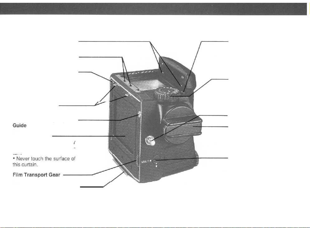
Never touch the surface of
the mirror.
want to change
remove
/
Ex-
the
red dot.
7
13 Gold Plated Contacts
These contacts interface the
AEPrism
dial on the film holder and
the shutter speeds.
Hot-shoe (X contact)
A
with
Lens Release Button
Auxiliary Release Contact
When the cover is moved to
the left. the contact appears.
This contact is used
nections of external
such as a special hand
and remote control unit.
Battery Check Button
LED displays the present
battery condition.
Finder with the ISO
cordless flash can be used
this
shoe.
for
con-
releases
grip
Page 9
Finder Coupling Panel (Front)
8
Finder
Coupling
Electric Contact for Film
Holder
This contact receives film
sensitivity data from the film
holder.
Film Holder Mount
Film Holder Coupling
Shutter Curtain
Exposures are controlled by
opening and closing the curtain
Film Holder Mounting
Bracket
Panel (Rear)
Pin
Shutter Speed Dial Lock
Release Button
This
button is used for unlocking the Shutter Speed
Dial from an AE position.
Shutter Speed Dial
This dial
selects the shutter
speed, and switches the
eration mode from AE
manual photography.
Neck Strap Lug
Film Advance Crank
A
Single complete turn cocks
the shutter and advances the
film for each exposure.
Multiple Exposure Lever
When this lever is set at
“MULTI”, film
even
when the Film Advance
/
Crank is turned.
ing multiple exposures on the
same film frame.
is not advanced
thus
op-
to
allow-
Page 10
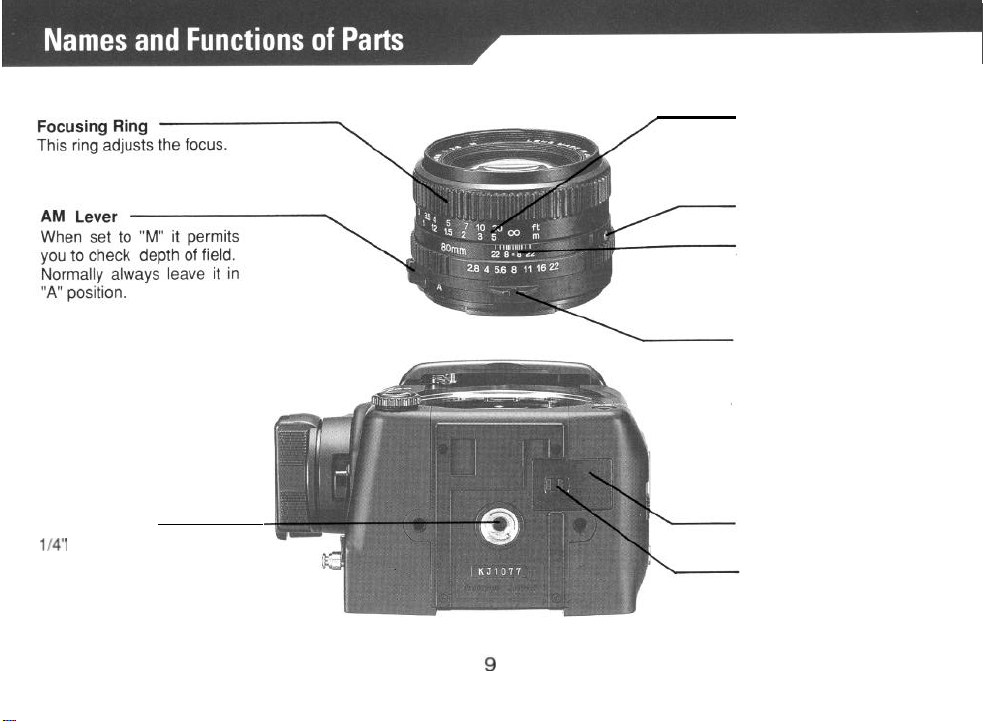
Distance Scale
The camera to subject distance can be set or confirmed
with this scale.
Lens Alignment Dot
Depth-of-field Scale
Provides a quick reading of
depth-of-field for various apertures and distances.
Exposure Meter Coupler
This coupler is engaged with
the Aperture Ring Coupling
Pin, transmitting diaphragm
information to the AE Prism
Finder.
Tripod Socket
1/4" tripod socket. To con-
vert to a
3/8" socket, remove
the small screw in the base of
the socket. Then remove the
bushing. See page 32.
Battery Chamber Cover
Battery Chamber Cover
Latch
Page 11
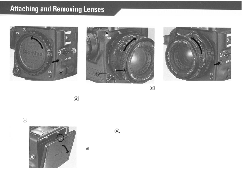
Removing the Front Body Cap and
Rear Cover
Attaching the Lens
Removing the Lens.
First remove the Front Body Cap in
the direction of the arrow, while
pushing the Lens Release Button
backwards as indicated by arrow.
Rear Body Protective Cover can be
readily removed by depressing the
part
of
@
as shown in the illustration.
8
Line up red Lens Alignment Dot
against red camera Alignment Dot
(C) and gently insert the lens into the
camera body. Then turn the lens
clock wise, as indicated by arrow,
until it clicks into place. Make sure
that the Aperture Ring Coupler Pin
is engaged with the Exposure Meter
Coupling Pin @, which sticks out
under the
camera.
*
When the Aperture Ring Coupler Pin is engaged
Mamiya name plate of the
@
While pushing lens release button backwards, turn lens counterclockwise.
(Same procedure as removing
cap).
by the exposure meter coupling pin lever, F/stop
data is conveyed to the AE Prism Finder.
10
body
Page 12
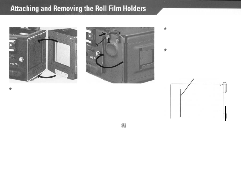
Attaching the Roll Film Holder
*
Remove the Roll Film Holder
Cover.
1. While spanning the Roll Film Holder
between your thumb and middle finger, holding it on the rubberized finger rests, carefully align its Film
Holder Mounting Bracket with the
corresponding center clip of the
camera body.
2. While keeping this alignment, press
the upper part of the Roll Film Holder
against the camera body, so that it
clicks into place by engaging the
spring loaded twin camera catch.
Removing the Roll Film Holder
1. Insert the Dark slide
marked by White Lines on the side
of the holder.
2. Push the lower one of the Film
Holder Detaching Lock Release
Button (A) downward, while simultaneously pushing the Film Holder
Detaching Button @I inward.
into
the slot
*
If the
Dark
Slide is not inserted,
the safety lock will prevent the
holder from being removed.
*
The Dark Slide can be inserted
in the Roll Film Holder up to the
Green Line, marked on the slide,
without affecting the image.
Green Line
11
Page 13
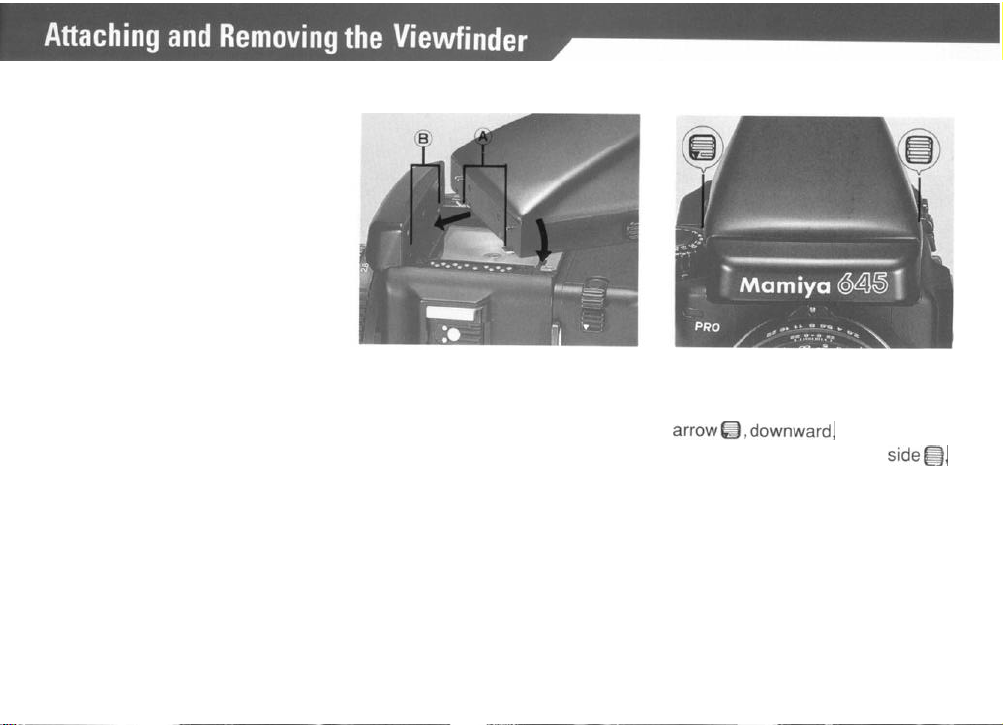
The same procedure applies to all
finders. The illustrations shows
the AE Prism Finder
FF401.
Attaching the Finder.
Removing the Finder
Lift the Upper Cover from the camera
body.
Insert the Attaching Latches (A) of the
finder into the Finder Coupling Panel
(B) in the front wall of the body. Press
the finder down until the rear latch
locks securely in place.
12
Spanning
gers, push the button on its right side
marked with a downward pointing
arrowQ,downward,
the other button, on the left
inward.
the finder with your fin-
while pushing
side@,
Page 14

Removing the Crank
Push
the
lock Lever (A) on its bottom
in a forward direction as far as
go (see illustration).
it
will
Attaching the Crank
With the flat part, having a White You may choose six different crank
Index Line, on top, line the Crank up
against its mounting plate on the side
of the body and push Film Advance
Crank Lock Lever backward.
starting positions to suit
The orientation of the crank
ence.
proper against its base, before it is
attached to the camera, will be
maintained when the entire assembly is locked into place.
your
prefer-
13
Page 15

Inserting the Battery
The camera will not function without a battery
Checking Battery
The camera will not function without a battery
With your fingernail, pull the Battery
Chamber Cover latch,
on the bottom
of the camera body, as indicated by
the arrow in the illustration. Lift the
cover off. The camera requires a 6V
alkaline, silver oxide or lithium battery. It is a good idea to wipe the
battery terminals before insertion to
assure proper contact. Observe po-
larity. + position is marked in battery
cavity.
InserttheOsidefirstatasteep
angle and then push entire battery
into place, making sure that the lift
ribbon wraps around battery. Close
cover by inserting twin-prong end first
and pushing it down.
*
Be particularly careful not to let
the lift ribbon cover
theOterminal.
14
Press Battery Check Button “B.C.”
(A) on lower front of the camera.
Battery Check Lamp (B) on top opposite side should light. Bright light
indicates good condition. Blinking
light means replace battery. No light
means battery is dead or improperly
inserted.
Page 16

Important:
1.
The sealed, new battery which is
supplied with this camera may have
been subject to storage conditions
which have reduced its service life.
Therefore it is desirable to replace it
with a fresh battery as soon
sible.
2. Carefully wipe the battery contacts before inserting into the chamber. Failure to do so may result in
poor electrical contact and consequent malfunctioning of the camera.
3. Always remove battery when
camera is not used for a while. Always carry spare batteries.
4. Battery life differs, depending on
type, age, storage condition, ambient
temperature, frequency of
use
as
pos-
etc.
Battery strength will be indicated
by whether the light:
Glows . . .
Blinks
Does not light
..Battery
. . . ..
strength is suf-
ficient.
Battery
capacity has
dropped below the allowable level. (Replace
the battery.)
. . . . ..
The
camera
will not work. (Replace
the battery.)
15
Page 17

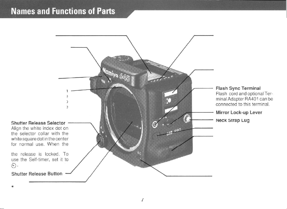
For normal operation set the White
Dot of the Shutter Release Selector
(A) against the White Square Dot
When set to the Red Dot 0, the
Release Button is locked.
*
Select this mode if the camera
will be idle for a period and to
prevent accidental shutter release. Also when the Power Drive
Grip is used.
Cl.
When set to the yellow clock symbol
0
the self-timer is operative. See
page 27 and 28 for further instruc-
tions.
Operating
the shutter
Release
Button
1. The Shutter Release Button
functions in two steps. Gentle pres-
sure will light the metering informa-
tion display if the AE Prism Finder is
used. Continued pressure will release the electromagnetic shutter.
16
@
2. If the film is not completely advanced, if the Dark Slide is not withdrawn or if the battery is dead, the
shutter will not function, even when
the Shutter Release Button is
pressed. This will also be the case if
the Shutter Speed Dial is set to “A”
or
“AEL”
when the AE Prism Finder
is not attached.
3. After releasing the shutter, the
Film Advance Crank will automati-
cally unlock and be ready to advance
the film.
Page 18

1. Attach the Roll Film
Holder to the camera body.
2. Pull out the Dark Slide
and place it into its Storage
Slot.
*
When only the body is tested, the familiarization
checkout can be made either in the “MULTI” or
3. Set the Shutter Speed
Dial to any other position
than ”A” or ”AEL”.
AE Prism Finder is not
mounted on the camera, the
shutter will not release if the
Shutter Speed Dial is in the
“A” or
“AEL”
When the
position.
0
(normal mode).
4. Set the Multiple Expo-
sure Lever on the body to
the “MULTI” position.
5. Set the Shutter Release
Selector to
mode), and press the Shut-
ter Release Button.
6. After the shutter has been
released, advance the Film
Advance Crank one com-
plete revolution and the next
frame will be ready.
“0”
(normal
____~~~
The empty film spool included with the film holder
supplied with a vinyl tube. When placed in the take-up
compartment it engages the film sensor and makes
the holder function as if it is loaded with film. Please
remove the tube after your test.
17
is
Page 19

1. While pushing the Back Cover
Lock Release Button (A) downward,
press the Back Cover Opening
ton, and the Back Cover will open.
But-
2. While squeezing in on both sides
of the Release Latch
Film Insert out of the camera body.
At that time,
in the upper part down to the lower
spood
move
compartment.
(A)
pull the Roll
the empty spool
Align
the right-hand side of this
3.
empty spool with the lower Spool
Stud (A) (convex). Slide the spool
into position making sure that the
left-side of the spool is properly held
by the Spool Clip.
When you load film
remove
and discard the protective
paper cover which is attached to the
in the
for
roll
film holder.
the first time,
18
Page 20

4. In the same manner, insert a roll
of film in the upper compartment. At
that time, check that the film leader
paper is set as shown in the photo
above. (The leader paper inside is
facing outward on the pressure plate.
Note that the film direction is wrong if
the leader paper is facing inward.)
5. Pull out some of the leader paper.
Insert the tip of the leader paper into
the slot of the lower Take-up Spool.
19
Gently rotate the take-up spool as
shown in the photo until the start
mark on the leader paper is aligned
with the start mark
clip.
*
Correctly align the start marks
(A)
on the spool
with each other, making sure that
the film feeds properly. When
proper
feeding occurs, the proper
im-
number of exposures may not be
taken.
*
Avoid exposing the film to direct sunlight when inserting or
removing film.
Page 21

Inserting the Roll Film Insert
Insert
the loaded Roll
into the holder, the
Film
film
roll on top,
Insert
while squeezing on both sides of the
Release Latch (A) as shown in illustration. Make sure that is been
properly seated and is locked in
place. Then close cover by firmly
pressing its top against the Roll Film
Holder.
*
To close the Back Cover, firmly
press the top of the
back cover on
both sides.
Film Speed
(ISO)
Dial
Each film holder has this important
feature. It electronically interfaces
the film holder with the AE Prism
Finder, the focal plane shutter and
the lens diaphragm, for exposure
automation.
This eliminates the need of having
to manually reset the meter, every
time you change film holders loaded
with different films. Therefore make
it a routine to always set this dial
with the speed of the loaded film.
The Memo Clip on the back of the
Roll Film Holder Cover accepts the
box top of the film carton and can
also be used for other reminders.
Page 22

Color Codes
Attach the loaded Roll Film Holder
to the camera. Remove Dark Slide
and store it. Turn the Multiple Exposure Lever (A) to its normal position,
White Dot against White Square.
Turn the Film Advance Crank until it
stops. The number “1” will now ap-
pear in the Film Counter Window.
The Focal Plane Shutter and Mirror
are now cocked and the camera is
ready for the first exposure.
Set the desired shutter speed against
the white index line (A) on the Shutter
Speed Dial.
1.
At the "A" and
"AEL"
settings, the
ShutterSpeed Dial is locked between
these two positions.
2. To release this lock, turn the Shutter Speed Dial while pushing the
Lock Release Button (B).
3. At all other settings the dial can be
rotated freely and each speed
number will click into place.
21
1. full seconds. All other numbers
(i.e.
are fractional seconds.
30 = 1/
30 sec.)
2. The yellow B indicates Bulb. At
thissettingtheshutterremainsopen
as long as the release is pressed.
3. The red 60 (1160 sec.) reminds
you that it is the fastest permissible
shutter speed setting when using
electronic flash.
1/
Page 23

4. “A and
“A
exposure lock) setting
used when the AE
“AEL”
explained
(auto exposure) and
Prism
“AEL”
must
Finder is
(auto
only be
attached to camera.
1.
If
it is not attached and the dial is
set to either of these positions, the
shutter release will not work.
2. If it is not attached and the
SelfTimer is activated, the Pilot Lamp
will
Iight for 10 seconds
but the shut-
ter will again not release.
If the Shutter Speed Dial is set
between click stops either the higher or
lower exposure speed may result.
22
Page 24

Set the desired f/stop on the Aperture Ring (A) by aligning the f/number
with the red reference dot
(B)
in the
center of the Scale Ring. The Aperture Ring has a click stop for each
f/
stop. In-between clicks can also be
used.
The effect the set f/stop will have
upon the picture area can be confirmed on the Finder Screen.
Move the AM Lever on the lens so
that “M” becomes visible - the lens
then can be stopped down to the
preselected aperture.
23
*At
position “A”, the lens is always stopped down only when
the shutter is being released with
the aperture being open.
*
During normal photography,
set the AM Lever so that “A” is
visible. At
“M”,
focusing will be a
little difficult.
* When using the AE Prism
Finder, be sure to set the AM Lever on “A”; otherwise, correct
exposure cannot be obtained.
*When aperture has been con-
firmed, be sure to reset the AM
Lever to “A”.
See “Depth-of-field” on page 25.
Page 25

Focusing with the Standard Focusing Screen N Type E
While looking through the viewfinder,
turn the lens Focusing Ring until the
most important subject part appears
sharp and clear.
1.
The camera comes equipped with
a bright, Type E, RangefinderlMicro-prism Focusing Screen. It features a center, split-image
rangefinder spot and the subject is in
sharp focus when the split images
combine into one.
2. The microprism ring around the
split-image center further facilitates
focusing. The microprisms disappear only when the subject is in
sharp focus.
24
3.
The rest of the ground glass area
can also be used for focusing.
*
Interchangeable Focusing
Screens
There are four additional focusing screens available for specialized applications. They are easy
to interchange and come with in-
structions.
Page 26

Depth of field is defined as the zone
of sharpness before and behind the
plane of focus. It depends on cam-
era subject/distance, focal length of
lens, aperture setting and distance
the lens is focused at.
Reading the Depth of Field Scale
In
addition
to visual observation, the
Depth of Field can be determined by
using the Depth of Field Scale on
each lens. f/stop numbers appear
on both the right and left side of the
red index mark in the center of the
scale ring. Simply read the figures
which appear above the f/stop num-
bers on the distance scale of the
Iens.
For example, with the
80mm
f/2.8N
lens focused at 3m and the aperture
set at f/22, the depth of field scale
indicates that the
cus will extend from
zone
of sharp
about 2m to 6m.
fo-
25
Page 27

1.
Giving the Film Advance Crank
one complete turn, will cock the
shutter and mirror and ready the
camera for the next exposure.
2. When the film is completely exposed (15 exposures on
120, 30
on
220 film), the crank stop will disengage. Continue turning until the paper trailer is completely wound onto
the take-up spool. (About five turns
after
the
last exposure.)
3. Open the Back Cover. and
move the
Roll
Film
Insert. The Expo-
re-
sure Counter will return to S (start)
automatically.
4. Pull the Spool Clip on the roll film
insert out to remove the film.
5. Remove the film from the roll film
insert;
make sure that the film on the
roll does not loosen, and seal immediately.
26
*
Move the empty spool from the
top to the lower (take-up) compartment, ready for loading the
next film roll.
*
Never load, unload or handle
film in direct sunlight.
Page 28

To use the Self-Timer, set the Shut-
0
ter Release Selector to
the Shutter Release Button. The
Battery Check Lamp will light for 8
seconds and blink for 2 seconds,
whereupon the shutter will go off.
and press
*
After using the self-timer mode,
be sure to return the Shutter
Release Selector to the White
Square. (Normal mode.)
+ To override the self-timer, after
having pressed the release, move
the selector back to the white
square.
*The Self-Timer can also be
overridden by inserting the Dark
Slide into the Film Holder or set-
ting the camera Shutter Speed
Dial to “B”.
27
Aligning the white dot of the Multiple
Exposure Lever with the yellow
“MULTI” square, disengages the
multiple exposure prevention
mechanism, and the film will not
advance after an exposure is made
and the Film Advance Crank is
turned. However, the shutter will be
recocked,
posures possible. In this mode the
Exposure Counter will not advance.
thus making multiple ex-
Page 29

*
To override the multiple exposure mode or to return to normal
operation, be sure to return the
lever’s
White Dot against the white
squareandthenadvancethefilm.
(If you forget you will continue to
make multiple exposures on the
same frame.)
For time exposures set the Shutter
0,
Release Selector to
timer mode, and set the Shutter
Speed Dial to
release and both mirror and shutter
“B”. Press the shutter
28
the self-
will stay open until the shutter re-
lease is pressed again. You may
also use a cable release together
with the cable release adapter. (The
battery circuit will automatically
switch off to save power.)
*
“B” can be terminated by shift-
ing the Shutter Release Selector
from $) or the Shutter Speed
Dial from
“B”.
Page 30

This is an important feature when
the tripod mounted camera is used
at slow or long exposure times and
particularly also with use of long
telephoto lenses. It eliminates the
possibility
ror
of
even
the slightest “mir-
bounce ”which may affect image
sharpness.
Move the Mirror-up Lever to the
yellow "M.UP" square, after you have
composed and focused your picture. This will raise the mirror and
the viewfinder image will be blacked
out.
After use,
return
lever to normal
(white square) position.
29
When using the AE Prism
*
Finder, set the Shutter Speed Dial
to “AEL”. Press the shutter release halfway and then lock the
mirror up. If set to “A” and the
mirror is locked up,
“LT” (long
time) will appear in the finder display and correct exposure cannot be obtained.
* When using a Leaf Shutter
Lens, be sure to read the instructions accompanying it.
Page 31

Infrared light rays - being of longer
wavelength - focus at a slightly different plane and require the follow-
ing adjustment:
1. Note
the Red Index Mark against
which you read your distance scale.
The red infrared index mark is slightly
to its right.
2. After focusing in the usual manner, read the distance scale and
move it to the right to line up with the
infrared index mark.
* For proper filter and exposure
information be sure to consult
the instructions enclosed with infrared film.
*
The A300mm f/2.8 APO lens for
645,
being also corrected for infrared light rays, does not need
an Index Mark for infrared.
30
Page 32

<Caution>
When using the Hot-shoe,
be sure to put an appropriate Safety Cover over the
Xsync terminal so that you
won’t
receive a
high voltage
electric shock if the terminal
is accidentally touched. (A
Safety Cover is put on the
Xsync terminal when the
camera leaves the factory.)
1. When using an electronic flash,
plug the synchronization cord into
the Sync Terminal and set the Shutter
Speed Dial to 1/60 sec.
*
The Mamiya 645 PRO has an X-
or slower.
sync terminal.
Attach a shoe-mount flash to the
hot-shoe of the camera or the Left
Hand Grip GL401 (optional).
Flash Synchronization Chart
~~~
31
*
Do not use a flash unit specifi-
cally
dedicated for another
era. It may
*
If you use a flash unit whose
damage
your 645 PRO.
cam-
flash duration is slower than 1/
1000 sec., set the shutter speed
dial to 1/30 sec. or slower.
Page 33

2. For MF and M bulbs, set the
Shutter Speed Dial to 1/30 sec.
slower for the MF type, and
or
1/15
sec. or slower for the M type.
* When using a flash, carefully
read the instructions that come
with the flash bulbs or flash unit
to check for appropriate shutter
speeds and to avoid malfunctions.
The Mamiya 645 PRO Tripod Socket
accepts a standard
mounting
screw. For use with tri-
pods having 3/8
1/4
"
tripod
"
mounting screws,
first unscrew the small black philips
head retaining screw in the
center
the tripod socket. Then remove the
1/4” bushing with a thin coin. To re
install the
1/4”
bushing, reverse the
process
32
of
-
Page 34

Eye-level Operation
Waist Level Operation
Hold the camera as shown in the
illustration, with its base resting
your left hand, the right hand supporting it from the side and top.
Press
both elbows against your body
and activate the shutter release with
a smooth, steady stroke.
on
For waist level operation,
able to have the Neck Strap attached
and adjusted for your size.
During exposure keep it taut and
press the camera firmly against your
body.
33
it
is desir-
* Handholding the camera is
even
easier
Grip WG401 or kept Hand Grip
GL401.
using
the Power Drive
Page 35

Attaching the Strap to the Camera
Removing the Strap from the Camera
1. While pushing down, pull out the
Neck Strap Fastener (A) of the at-
taching
clip.
2. Place the hole of the strap
tener
(A)
over the Neck Strap on the
fas-
camera body as illustrated, and pull
until it clicks and locks into place.
34
With your fingers, puII the Neck Strap
Fastener
ward and push
(A)
of the attaching clip up-
part (B)
in the direc-
tion of the arrow. The strap can now
be removed.
* When attaching the Strap to the
Neck Strap Lug on the side of the
camera with the Film Advance
Crank, insert the neck strap fas-
tener (A) into the lower part of the
double slot.
Page 36

6 x 4.5cm
electronic focal-plane shutter SLR
Film loading
Polaroid pack film (Polaroid
135 roll film in film cartridge
Daylight loading-interchangeable film holders with film speed dial available
100,
600 series)
Standard lenses
Lens
mount
Shutter
Shutter speed
Shutter release
M645 bayonet
Moving coil, electronic controlled focal-plane shutter
(Manual) 4 sec. - 1/1000 sec., B (T)
(Auto) 8 sec. Electromagnetic release.
Selectable release lock or self-timer mode.
mount
(applicable to all
1/1,000
sec. (when the AE Prism Finder FE401 is used)
M645
Mirror
Viewfinder
Focusing screen
Interchangeable (Waist Level Finder N, Prism Finder
(Viewfinders for the M645 Super can be used)
(Same as the M645 Super)
Field of view
..___
lenses)
lock~up
capability.
FP401
and AE Prism Finder FE401
Fresnel
Lens, accessory screens available
Page 37

Film transport
Exposure counter
Multiple
Depth-of-field
Self-timer
Battery check
Back cover
Power supply
exposure
Single turn winding by Film Advance Crank
Variable crank start
Interchangeable (Power
Progressive type: automatic reset.
The counter for 120 and 220 film will be automatic.
Activated by the Multiple Exposure Lever.
Depth-of-field Scale provided on lens
:
Electronic LED display Lights for 8 seconds, flashes for 2 seconds, before shutter release.
j
Has manual override.
The-Battery Check Button, indicates residual battery capacity in 3 stages.
Time (T) photography can be taken.
position@
(6 positions).
Grip WG401 and Power Drive Grip N
Drive
Control and Electronic Cable Releases.
shoe, Flash synchronization at
AC401.
).
..___
..___
..
1/60 sec.
or slower speeds
Others
Dimenslons & Weight
Body with 120 Roll Film Holder HA401 124mm (W) x102.5mm (H)
With Waist Level Finder N,
With Prism Finder FP401, 80mm f/2.8N
With AE Prism Finder FE401, 80mm f/2.8N
With Power Drive Grip
AE Prism Finder FE4
WG401,
1, 80mm f/2.8N
0
With Neck Strap.
80mm
f2.8N
124mm (W) x106 mm (H) x
124mm
(W) x128 mm (H) x
124mm
(W) x135 mm (H) x 170mm
172mm (W) x135 mm (H)
36
x
124mm (D)
158mm (D)
170mm
x
170mm
(D)
(D)
(D)
980g
1,345g
1,530g
1,545g
1,800g
(Without Battery)
Page 38

*
If the camera should fail to function properly,
please check the following:
1.
The Shutter Release Button does not move.
Push the Battery Check Button.
If the lamp does not light, check:
Is a Battery in the camera?
If yes, is it correctly inserted? (Polarity)
Is it dead?
If the lamp does light, check:
Has the Film Holder Dark Slide been pulled?
Is the Shutter Release Selector in the locked
(Red Dot) position?
If so, move it to the White Square and try again
Is the Shutter Speed Dial in the “A” or
position?
If so, turn to other setting and try again.
“AEL”
or
2. The finder is black
Has the Lens Cap been removed?
Is the Mirror-up Lever in the
If so, turn the lever to the White Square.
Is the “AM” setting on the lens at “M" (Depth of
Field Preview)?
If so, move it to “A”.
3. The Roll Film Holder cannot be removed from the
camera body.
Insert the Dark Slide.
4. The developed film has fewer exposures than
specified.
Most likely
properly when the film was loaded. (See load
ing instructions page 20
5.
The Film Advance Crank continues to turn and does
not stop.
Was the Roll Film Insert placed in the Roll Film
Holder?
Was the empty fim spool left in the upper
compartment?
37
very dark.
“M.UP”
the
Start Mark had not been aligned
)
position?
Page 39

*
Cold Temperature Photography
a. Use a fresh lithium battery
b. Utilize the External Battery Case accessory.
(Permits battery to be placed inside clothing).
Batteries that fail at low temperatures may still
be used at normal temperatures. However frequent temperature changes shortens
c. Avoid sudden temperature changes when going
indoors, to prevent moisture condensation on
camera and
protection).
lenses. (Also important for film
battery life.
Things to Watch
*
When using the AE Prism Finder FE401
When using this finder it is imperative that the
Film Speed Dial on the Roll Film Holder is prop-
erly set for the ISO number of the loaded film, as
it interfaces with this finder. If not done, wrong
exposures may result.
*When the mirror is locked in the up position.
* The Focal Plane Shutter Curtain may be dam-
aged if the camera faces strong light sources,
especially the sun. Return mirror to normal po-
sition or cap lens to prevent such damage.
38
Page 40

The AE Prism Finder FE401
The Mamiya AE (Automatic Exposure) Prism Finder
FE401 pentaprism guarantees a true, upright image
and features built-in electronic shutter control which,
ensures aperture-priority, TTL automatic exposure
metering while in the A or AEL mode.
< 3-Way
Metering System>
The FE401 comes with three metering modes: average
metering
(AV), spot metering (SP), and AV-SP metering
capable of automatically selecting AV or SP according
to subject conditions.
The LED display in the viewfinder indicates correct
exposure
If you forget to extract the Dark Slide when the finder is
being used with the 645 PRO, an LED will flash a
warning.
The Power Drive Grip WG401
The Power Drive Grip WG401 is integral with the
winder and hand grip, enabling quick and continuous
exposures to be taken: frames can be advanced (about
2
frames/sec.).
Usable with any of three recently developed leaf shutter lenses, it
with the Grip Connecter
can
be connected with the
PL401,
lens and
winder
thus automatically
interlocking it with the lens.
39
Page 41

Roll Film Holders
Interchangeable Lenses
:
120 Roll Film Holder HA401
220 Roll Film Holder HB401
135 Roll Film Holder
(with Panoramic Adapter)
Polaroid Land Pack Film Holder HP401
HC401
Wide-angle Lenses
Telephoto Lenses
Standard Lenses
Zoom Lenses
Special Effect Lenses:
Leaf Shutter Lenses
TeleConverter
40
:
35mm
:
150mm f/3.5N, A150mm
ULD300mm f/5.6N, A300mm
:
80mm f/1 .9N, 80mm f/2.8N,
110mm
: Zoom 55
2 x Tele-Converter
f/3.5N,
45mm
55mm
f/2.8N
210mm
f/2.8AP0,
Zoom ULD105 - 210mm f/4.5
Fish-eye ULD24mm f/4,
50mm
Soft
:
f/2.8N/L, A150mm
f/4N
W2.8N
f/4,
145mm
A55mm
500mm f/5.6
-
110mm f/4.5N,
Macro 80mm
f/4
f/2.8N/L,
f/2.8N,
f/2.8,
Shift
f/4N
A80mm
f/3.8N/L
Page 42

Page 43

When the camera is not used for a long period of time,
remove
the battery and any film from the camera.
Avoid storing the camera for prolonged periods of time
in a damp or salty atmosphere. (Color film should be
stored at the manufacturer’s recommended temperatures.)
Since cameras are precision instruments, avoid shocks
and rough handling.
When camera and lens are stored for a long time,
periodically exercise the shutter(s) at various speeds
and also turn the lens diaphragms.
Cleaning
Never touch the surface coated mirror. Clean dust
particles with a blower and optical surfaces with lens
cleaning tissue and lens cleaner.
Periodic Check
Periodically check the camera to make sure that it is in
good working order, especially before an important
assignment. Check the battery, flash synchronization,
mirror and shutter movement, film advance, diaphragm
operation, etc.
Should any malfunction occur or if the camera has
been dropped, jarred or become wet, do not attempt to
fix it yourself but send it to the Service Department of
your Mamiya distributor.
42
 Loading...