

Page 1
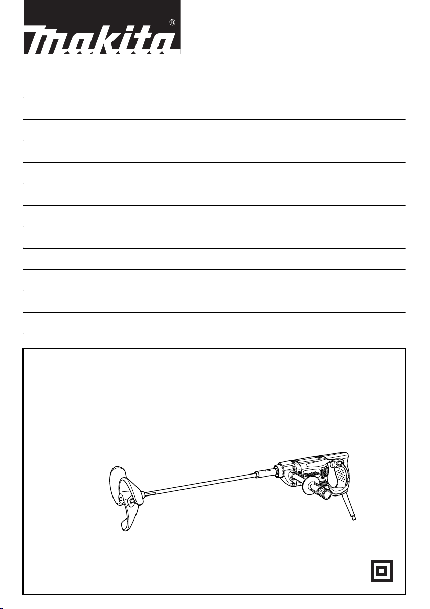
GB Power Mixer Instruction manual
F Mélangeur électrique Manuel d’instructions
D Rührgerät Betriebsanleitung
I Miscelatore elettrico Istruzioni per l’uso
NL Elektrische menger Gebruiksaanwijzing
E Mezcladora eléctrica Manual de instrucciones
P Misturadora eléctrica Manual de instruções
DK Motormixer Brugsanvisning
S Elektrisk omrörare Bruksanvisning
N Mørtelmikser Bruksanvisning
SF Sekoituskone Käyttöohje
GR Αναδευτήρας Οδηγίες χρήσης
UT2204
Page 2
1
2
3
12
7
4
5
6
8
7
34
9
10
5
11
56
9
5
10
5
11
78
2
Page 3
12
13
15
14
910
14
16
11
3
Page 4
ENGLISH
Explanation of general view
1. Lock button
2. Switch trigger
3. Indicator lamp
4. Hex nut
5. Shaft
6. Shaft holder
7. Wrench 19
8. Notch
9. Mixing blade
10. Hex bolt
11. Flat surface
12. Filter
13. Cover
14. Screwdriver
15. Limit mark
16. Brush holder cap
SPECIFICATIONS
Model UT2204
No load speed (min
Mixing blade diameter 220 mm
Overall length 929 mm
Net weight 3.7 kg
Safety class /II
• Due to our continuing program of research and development, the specifications herein are subject to change without
notice.
• Note: Specifications may differ from country to country.
Symbols
The following show the symbols used for the equipment.
Be sure that you understand their meaning before use.
................ Read instruction manual.
................ DOUBLE INSULATION
Intended use
The tool is intended for mixing wall materials, etc. (except
flammable materials)
Power supply
The tool should be connected only to a power supply of
the same voltage as indicated on the nameplate, and can
only be operated on single-phase AC supply. They are
double-insulated in accordance with European Standard
and can, therefore, also be used from sockets without
earth wire.
-1
) 550
END201-2
ENE056-1
ENF002-1
SPECIFIC SAFETY RULES GEB001-2
DO NOT let comfort or familiarity with product (gained
from repeated use) replace strict adherence to drill
safety rules. If you use this power tool unsafely or
incorrectly, you can suffer serious personal injury.
1. Use auxiliary handles supplied with the tool. Loss
of control can cause personal injury.
2. Hold power tools by insulated gripping surfaces
when performing an operation where the cutting
tool may contact hidden wiring or its own cord.
Contact with a “live” wire will make exposed metal
parts of the tool “live” and shock the operator.
3. Always be sure you have a firm footing.
Be sure no one is below when using the tool in
high locations.
4. Hold the tool firmly.
5. Keep hands away from rotating parts.
6. Do not leave the tool running. Operate the tool
only when hand-held.
7. Do not touch the drill bit or the workpiece immediately after operation; they may be extremely hot
and could burn your skin.
8. Some material contains chemicals which may be
toxic. Take caution to prevent dust inhalation and
skin contact. Follow material supplier safety data.
SAVE THESE INSTRUCTIONS
WARNING:
MISUSE or failure to follow the safety rules stated in
this instruction manual may cause serious personal
injury.
4
Page 5

FUNCTIONAL DESCRIPTION
CAUTION:
• Always be sure that the tool is switched off and
unplugged before adjusting or checking function on the
tool.
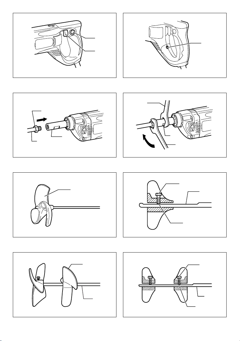
Switch action (Fig. 1)
CAUTION:
• Before plugging in the tool, always check to see that
the switch trigger actuates properly and returns to the
“OFF” position when released.
To start the tool, simply pull the switch trigger. Release the
switch trigger to stop.
For continuous operation, pull the switch trigger and then
push in the lock button.
To stop the tool from the locked position, pull the switch
trigger fully, then release it.
Indicator lamp (Fig. 2)
The green power-ON indicator lamp lights up when the
tool is plugged to the mains. If the indicator lamp is lit but
the tool does not start even if the tool is switched ON, the
carbon brushes may be worn out, or the motor or the
switch may be defective. If the indicator lamp does not
light up, the mains cord or the indicator lamp may be
defective. When the mains cord is defective, the tool neither starts nor lights the indicator lamp. When the indicator
lamp is defective, the tool starts without the indicator lamp
lighting up.
ASSEMBLY
CAUTION:
• Always be sure that the tool is switched off and
unplugged before carrying out any work on the tool.
Installing shaft (Fig. 3 & 4)
Tighten the shaft with hex. Nut into the shaft holder as far
as the hex nut comes into contact with the holder. Hold
the notch in the shaft holder with wrench 19 so that it cannot revolve. With the notch held so, tighten the hex nut
with another wrench 19 in the direction of arrow.
Installing mixing blades (Fig. 5 & 6)
Insert the mixing blade into the shaft and secure it with the
hex bolt.
At this time, position it so that the top end of the hex bolt
always fits to the flat surface on the shaft and tighten the
hex bolt with the provided wrench.
When installing the mixing blades at two different positions (which is applicable only to the mixing blades
allowed to do so), mount and secure the two mixing
blades on the flat part of the shaft with the hex bolts so
that the same surface of blades faces each other as
shown in the figure. (Fig. 7 & 8)
OPERATION
Mixing
CAUTION:
• Do not use to mix flammable material such as paint
with thinner used as solvent. Failure to do so may
cause injury.
1. Hold the rear handle of the tool with one hand and the
grip with the other hand firmly, place the mixing blade
under material fully and turn on the tool after making
sure work site safety.
2. Move the mixing blade up and down during the mixing
operation so that whole part of material can be mixed.
3. When finishing mixing, turn off the tool, make sure that
the mixing blade has come to a complete stop, and
then pull it out of the vessel.
MAINTENANCE
CAUTION:
• Always be sure that the tool is switched off and
unplugged before attempting to perform inspection or
maintenance.
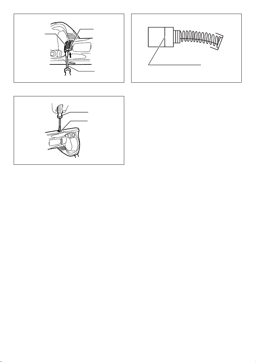
Replacing filter (Fig. 9)
Replace the filter regularly as the cooling efficiency of the
tool is reduced due to built-up dust or particles in the filter.
Insert the slotted bit screwdriver and the like between the
tool and the cover as shown in the figure. Lift it up just like
using a shovel and remove the cover.
Replace the filter in the cover with a new one.
Reinstall the cover on the tool.
Replacing carbon brushes (Fig. 10)
Remove and check the carbon brushes regularly. Replace
when they wear down to the limit mark. Keep the carbon
brushes clean and free to slip in the holders. Both carbon
brushes should be replaced at the same time. Use only
identical carbon brushes.
Use a screwdriver to remove the brush holder caps. Take
out the worn carbon brushes, insert the new ones and
secure the brush holder caps. (Fig. 11)
To maintain product SAFETY and RELIABILITY, repairs,
any other maintenance or adjustment should be performed by Makita Authorized Service Centers, always
using Makita replacement parts.
ACCESSORIES
CAUTION:
• These accessories or attachments are recommended
for use with your Makita tool specified in this manual.
The use of any other accessories or attachments might
present a risk of injury to persons. Only use accessory
or attachment for its stated purpose.
If you need any assistance for more details regarding
these accessories, ask your local Makita Service Center.
• Mixing blades
• Shaft
5
Page 6

NEDERLANDS
Verklaring van het onderdelenoverzicht
1. Vergrendelknop
2. Aan/uit-schakelaar
3. Bedrijfslampje
4. Zeskantmoer
5. As
6. Ashouder
7. Sleutel 19
8. Platte kant
9. Schoepenwiel
10. Zeskantbout
11. Platte kant
12. Filter
13. Afdekking
14. Schroevendraaier
15. Slijtgrensmarkering
16. Koolborsteldop
TECHNISCHE GEGEVENS
Model UT2204
Onbelaste snelheid (min
Diameter van schoepenwiel 220 mm
Totale lengte 929 mm
Netto gewicht 3,7 kg
Veiligheidsklasse /II
• Als gevolg van ons doorlopende onderzoeks- en ontwikkelingsprogramma, zijn de technische gegevens van dit
gereedschap onderhevig aan veranderingen zonder voorafgaande kennisgeving.
• Opmerking: De technische gegevens kunnen van land tot land verschillen.
Symbolen
Hieronder staan de symbolen die voor dit gereedschap
worden gebruikt.
Zorg ervoor dat u weet wat ze betekenen alvorens het
gereedschap te gebruiken.
................ Lees de gebruiksaanwijzing.
................ DUBBEL GEÏSOLEERD
Gebruiksdoeleinden
Het gereedschap is bedoeld voor het mengen van
stucmaterialen, enz. (behalve brandbare materialen).
Voe din g
Het gereedschap mag uitsluitend worden aangesloten op
een voeding met dezelfde spanning als aangegeven op
het identificatieplaatje en werkt alleen op enkele-fase
wisselstroom. Het gereedschap is dubbel geïsoleerd
volgens de Europese norm en mag derhalve ook op een
niet-geaard stopcontact worden aangesloten.
-1
) 550
END201-2
SPECIFIEKE
VEILIGHEIDSVOORSCHRIFTEN
Laat u NIET misleiden door een vals gevoel van
comfort en bekendheid met het gereedschap (na
veelvuldig gebruik) en neem alle
veiligheidsvoorschriften van de schroefboormachine
altijd strikt in acht. Bij onveilig of verkeerd gebruik
van het elektrisch gereedschap, bestaat de kans op
ernstig persoonlijk letsel.
1. Gebruik de hulphandgrepen die bij het
ENE056-1
ENF002-1
gereedschap werden geleverd. Als u de controle
over het gereedschap verliest, kan dit leiden tot
ernstig persoonlijk letsel.
2. Houd elektrisch gereedschap vast aan het
geïsoleerde oppervlak van de handgrepen
wanneer u werkt op plaatsen waar het
zaaggereedschap met verborgen bedrading of zijn
eigen snoer in aanraking kan komen. Door contact
met onder spanning staande draden, zullen de nietgeïsoleerde metalen delen van het gereedschap
onder spanning komen te staan zodat de gebruiker
een elektrische schok kan krijgen.
3. Zorg er altijd voor dat u stevig staat.
Zorg ervoor dat er niemand zich onder u bevindt
wanneer u het gereedschap op een hoge plaats
gebruikt.
4. Houd het gereedschap stevig vast.
5. Houd uw handen uit de buurt van draaiende delen.
6. Laat het gereedschap niet ingeschakeld liggen.
Bedien het gereedschap alleen wanneer u het
vasthoudt.
7. Raak het schroef- of boorbit en het werkstuk niet
onmiddellijk na gebruik aan. Zij kunnen bijzonder
heet zijn en brandwonden op uw huid
veroorzaken.
GEB001-2
15
Page 7

8. Sommige materialen bevatten chemische stoffen
die giftig kunnen zijn. Neem
voorzorgsmaatregelen tegen het inademen van
stof en contact met de huid. Volg de
veiligheidsinstructies van de leverancier van het
materiaal op.
BEWAAR DEZE
VOORSCHRIFTEN
WAARSCHUWING:
VERKEERD GEBRUIK of het niet volgen van de
veiligheidsinstructies in deze gebruiksaanwijzing kan
leiden tot ernstig persoonlijk letsel.
BESCHRIJVING VAN DE
FUNCTIES
LET OP:
• Controleer altijd of het gereedschap is uitgeschakeld
en de stekker uit het stopcontact is getrokken alvorens
de functies van het gereedschap te controleren of af te
stellen.
In- en uitschakelen (zie afb. 1)
LET OP:
• Controleer altijd, voordat u de stekker in het
stopcontact steekt, of de aan/uit-schakelaar op de
juiste manier schakelt en weer terugkeert naar de uitstand nadat deze is losgelaten.
Om het gereedschap in te schakelen, knijpt u gewoon de
aan/uit-schakelaar in. Laat de aan/uit-schakelaar los om
het gereedschap te stoppen
Om het gereedschap continu te laten werken, knijpt u de
aan/uit-schakelaar in en drukt u vervolgens op de
vergrendelknop.
Om vanuit de vergrendelde werking het gereedschap te
stoppen, knijpt u de aan/uit-schakelaar helemaal in en
laat u deze vervolgens weer los.
Bedrijfslampje (zie afb. 2)
Het bedrijfslampje brandt groen wanneer het
gereedschap op het lichtnet is aangesloten. Als het
bedrijfslampje brandt, maar het gereedschap niet start,
zelfs niet wanneer de schakelaar in de aan-stand wordt
gezet, kunnen de koolborstels versleten zijn, of kan de
motor of schakelaar defect zijn. Als het bedrijfslampje niet
brandt, kan het netsnoer beschadigd zijn of het lampje
zelf kapot zijn. Als het netsnoer defect is, zal het
gereedschap niet kunnen worden ingeschakeld en brandt
het bedrijfslampje niet. Als het lampje stuk is, start het
gereedschap zonder dat het bedrijfslampje brandt.
ONDERDELEN AANBRENGEN/
VERWIJDEREN
LET OP:
• Controleer altijd of het gereedschap is uitgeschakeld
en de stekker uit het stopcontact is getrokken alvorens
enige werk aan het gereedschap uit te voeren.
16
De as monteren (zie afb. 3 en 4)
Draai de as zo ver mogelijk in de ashouder en zet de as
vast met de zeskantmoer zodat deze tegen de ashouder
komt. Houd daarbij de platte kant in de ashouder op zijn
plaats met een sleutel 19 zodat de ashouder niet
meedraait. Terwijl u de platte kant stilhoudt, draait u de
zeskantmoer in de richting van de pijl vast met een
andere sleutel 19.
Het schoepenwiel monteren (zie afb. 5 en
6)
Plaats het schoepenwiel op het uiteinde van de as en zet
het vast met de zeskantbout.
Let er daarbij op dat de punt van de zeskantbout aangrijpt
op de platte kant van de as, en zet dan de zeskantbout
vast met de bijgeleverde sleutel.
Wanneer u twee schoepenwielen op de as monteert (wat
alleen acceptabel is voor schoepenwielen waarvoor dit
toegestaan is), monteert u de twee schoepenwielen ieder
met behulp van een zeskantbout op het platte deel van de
as, zodanig dat van ieder schoepenwiel dezelfde kant
tegenover elkaar ligt.(zie afb. 7 en 8)
BEDIENING
Mengen
LET OP:
• Gebruik het gereedschap niet om brandbare
materialen te mengen, zoals verf met verdunner dat
gebruikt wordt als oplosmiddel. Als u dat toch doet, kan
letsel worden veroorzaakt.
1. Houd de achterhandgreep van het gereedschap met
één hand en de zijhandgreep met de andere hand
stevig vast, houdt het schoepenwiel helemaal onder
het mengmateriaal en schakel het gereedschap in
nadat u zich van de veiligheid van de werkplek hebt
overtuigd.
2. Beweeg het schoepenwiel tijdens het mengen op en
neer zodat al het materiaal gelijkmatig wordt gemengd.
3. Nadat het mengen klaar is, schakelt u het
gereedschap uit, en nadat u zeker weet dat het
schoepenwiel stilstaat, trekt u het schoepenwiel uit het
gemengde materiaal.
ONDERHOUD
LET OP:
• Zorg er altijd voor dat de machine is uitgeschakeld en
de stekker uit het stopcontact is getrokken, voordat u
een inspectie of onderhoud uitvoert.
Het filter vervangen (zie afb. 9)
Vervang het filter regelmatig aangezien het koelvermogen
van het gereedschap afneemt naarmate zich stof en
deeltjes ophopen in het filter.
Steek een platkopschroevendraaier of iets dergelijks
tussen het gereedschap en de afdekking, zoals
aangegeven in de afbeelding. Wrik met de punt van de
schroevendraaier de afdekking omhoog en verwijder
deze.
Page 8

Vervang het filter in de afdekking door een nieuwe.
Plaats de afdekking terug op het gereedschap.
De koolborstels vervangen (zie afb. 10)
Verwijder en controleer de koolborstels regelmatig.
Vervang deze wanneer ze tot aan de slijtgrensmarkering
zijn afgesleten. Houd de koolborstels schoon en zorg
ervoor dat ze vrij kunnen bewegen in de houders. Beide
koolborstels dienen tegelijkertijd te worden vervangen.
Gebruik alleen identieke koolborstels.
Gebruik een schroevendraaier om de koolborsteldoppen
te verwijderen. Haal de versleten koolborstels eruit, plaats
de nieuwe erin, en zet de koolborsteldoppen goed vast
(Zie afb. 11).
Om de VEILIGHEID en BETROUWBAARHEID van het
gereedschap te handhaven, dienen alle reparaties,
onderhoud en afstellingen te worden uitgevoerd door een
erkend Makita-servicecentrum, en altijd met
gebruikmaking van originele Makitavervangingsonderdelen.
ACCESSOIRES
LET OP:
• Deze accessoires of hulpstukken worden aanbevolen
voor gebruik met het Makita-gereedschap dat in deze
gebruiksaanwijzing wordt beschreven. Het gebruik van
andere accessoires of hulpstukken kan gevaar voor
persoonlijk letsel opleveren. Gebruik de accessoires of
hulpstukken uitsluitend voor de aangegeven
gebruiksdoeleinden.
Mocht u meer informatie willen hebben over deze
accessoires, dan kunt u contact opnemen met uw
plaatselijke Makita-servicecentrum.
• Schoepenwiel
•As
17
Page 9

ENGLISH
For European countries only
Noise and Vibration
The typical A-weighted sound pressure level is 83 dB (A).
Uncertainty is 3 dB (A).
The noise level under working may exceed 85 dB (A).
– Wear ear protection. –
The typical weighted root mean square acceleration value is
not more than 2.5 m/s
These values have been obtained according to EN60745.
2
.
ITALIANO
Modello per l’Europa soltanto
Rumore e vibrazione
Il livello tipico di pressione sonora ponderato A è di 83 dB (A).
Eventuali variazioni sono comprese in 3 dB (A).
Il livello acustico in esercizio può superare 85 dB (A).
– Indossare una protezione acustica. –
In genere, il valore efficace ponderato dell'accelerazione non
supera i 2,5 m/s
Questi valori sono stati ottenuti in conformità con la norma
EN60745.
2
.
FRANÇAIS
Pour les pays d’Europe uniquement
Bruit et vibrations
Le niveau de pression sonore pondérée A typique est 83 dB
(A).
L'incertitude est de 3 dB (A).
Le niveau de bruit peut dépasser 85 dB (A) lors de l'utilisation.
– Portez des protections d’oreilles. –
La valeur d'accélération quadratique pondérée typique ne
dépasse pas 2,5 m/s
Ces valeurs ont été obtenues selon EN60745.
2
.
DEUTSCH
Nur für europäische Länder
Geräusch- und Vibrationsentwicklung
Der typische Schalldruck beträgt 83 dB (A).
Die Abweichung beträgt 3 dB (A).
Unter Arbeitsbedingungen kann der Schalldruck 85 dB (A)
überschreiten.
– Tragen Sie Gehörschutz. –
Der typische effektive Beschleunigungswert beträgt höchstens
2
.
2,5 m/s
Diese Werte wurden entsprechend der Norm EN60745
gewonnen.
Yasuhiko Kanzaki
NEDERLANDS
Alleen voor Europese landen
Geluidsniveau en trilling
Het typische, A-gewogen geluidsdrukniveau is 83 dB (A).
De afwijking is 3 dB (A).
Het geluidsniveau kan tijdens gebruik hoger worden dan
85 dB (A).
– Draag gehoorbescherming. –
De typisch, gewogen, kwadratisch-gemiddelde
versnellingswaarde is niet hoger dan 2,5 m/s
Deze waarden zijn verkregen volgens EN60745.
2
.
ESPAÑOL
Para países europeos solamente
Ruido y vibración
El nivel de presión acústica típico ponderado A es de 83 dB
(A).
La incertidumbre es de 3 dB (A).
El nivel de ruido durante el trabajo puede superar los 85 dB
(A).
– Utilice protección para los oídos. –
El valor ponderado de aceleración no es superior a 2,5 m/s
Estos valores se han obtenido conforme a EN60745.
CE 2005
2
.
Director Amministratore
Directeur Directeur
Direktor Director
MAKITA INTERNATIONAL EUROPE LTD.
Michigan Drive, Tongwell, Milton Keynes,
Bucks MK15 8JD, ENGLAND
Responsible manufacturer: Produttore responsabile:
Fabricant responsable : Verantwoordelijke fabrikant:
Verantwortlicher Hersteller: Fabricante responsable:
Makita Corporation Anjo Aichi Japan
37
Page 10

PORTUGUÊS
Só para países Europeus
Ruído e vibração
O nível acústico ponderado A é de 83 dB (A).
O coeficiente de imprecisão é de 3 dB (A).
O nível de ruído quando em funcionamento pode exceder os
85 dB (A).
– Use protecção para os ouvidos. –
A raiz quadrada do valor médio ponderado da variação da
aceleração não é superior a 2,5 m/s
Estes valores foram obtidos segundo a norma EN60745.
2
.
NORSK
Gjelder bare land i Europa
Støy og vibrasjon
Typisk A-vektet lydtrykknivå er 83 dB(A).
Usikkerheten er på 3 dB(A).
Støynivået under arbeid kan overskride 85 dB(A).
– Bruk hørselvern. –
Typisk vektet kvadratisk middelverdi av akselerasjonen er ikke
mer enn 2,5 m/s
Disse verdiene er fremkommet i samsvar med EN60745.
2
.
DANSK
Kun for lande i Europa
Lyd og vibration
Det typiske A-vægtede lydtryksniveau er 83 dB (A).
Usikkerheden er 3 dB (A).
Støjniveauet under arbejdet kan være højere end 85 dB (A).
– Bær høreværn. –
Den typiske vægtede effektive accelerationsværdi er ikke over
2
2,5 m/s
.
Disse værdier er målt i overensstemmelse med EN60745.
SVENSKA
Endast för Europa
Buller och vibration
Den typiska ljudtrycksnivån är 83 dB (A).
Mättoleransen är 3 dB (A).
Bullernivån under drift kan överstiga 85 dB (A).
- Använd hörselskydd. –
Kvadratiska medelvärdet för accelerationen överstiger inte
2
2,5 m/s
.
Dessa värden är framtagna i enlighet med EN60745.
Yasuhiko Kanzaki
SUOMI
Vain Euroopan maat
Melutaso ja tärinä
Tyypillinen A-painotettu äänenpainetaso on 83 dB (A).
Virhemarginaali on 3 dB (A).
Työskentelyn aikana melutaso voi ylittää 85 dB (A).
– Käytä kuulosuojaimia. –
Tyypillinen painotettu tehollisarvo on enintään 2,5 m/s
2
.
Nämä arvot on saatu standardin EN60745 mukaisesti.
ΕΛΛΗΝΙΚΑ
Μνο για χώρες της Ευρώπης
Θρυβος και κραδασFς
Το σύνηθες σταθµισµένο επίπεδο ηχητικής πίεσης είναι
83 dB (A).
Η αβεβαιτητα είναι 3 dB (A).
Το επίπεδο θορύβου σε λειτουργία ενδέχεται να υπερβεί
τα 85 dB (A).
– Να φοράτε ωτοασπίδες. –
Η συνήθης σταθµισµένη µέση τετραγωνική ρίζα της τιµής
επιτάχυνσης δεν υπερβαίνει τα 2,5 m/s
Οι τιµές αυτές έχουν ληφθεί σύµφωνα µε το EN60745.
CE 2005
2
.
Director Direktor
Direktør Johtaja
Direktör ∆ιευθυντής
MAKITA INTERNATIONAL EUROPE LTD.
Michigan Drive, Tongwell, Milton Keynes,
Bucks MK15 8JD, ENGLAND
Fabricante responsável: Ansvarlig produsent:
Ansvarlig fabrikant: Vastaava valmistaja:
Ansvarig tillverkare: Yπεύθυνος κατασκευαστής:
38
Makita Corporation Anjo Aichi Japan
Page 11

ENGLISH
EC-DECLARATION OF CONFORMITY
We declare under our sole responsibility that this product is in
compliance with the following standards of standardized
documents, EN60745, EN55014, EN61000 in accordance with
Council Directives, 89/336/EEC, 98/37/
EC.
ITALIANO
LE NORME DELLA COMUNITÀ EUROPEA
Dichiariamo sotto la nostra sola responsabilità che questo
prodotto è conforme agli standard di documenti standardizzati
seguenti: EN60745, EN55014, EN61000 secondo le direttive
del Consiglio 89/336/CEE e 98/37/CE.
FRANÇAIS
DÉCLARATION DE CONFORMITÉ CE
Nous déclarons sous notre entière responsabilité que ce
produit est conforme aux normes des documents standardisés
suivants, EN60745, EN55014, EN61000 conformément aux
Directives du Conseil, 89/336/CEE et 98/37/EG.
DEUTSCH
Hiermit erklärt wir unter unserer alleinigen Verantwortung, daß
dieses Produkt gemäß den Ratsdirektiven 89/336/EWG und
98/37/EG mit den folgenden Normen von Normendokumenten
übereinstimmen: EN60745, EN55014, EN61000
CE-KONFORMITÄTSERKLÄRUNG
NEDERLANDS
EG-VERKLARING VAN CONFORMITEIT
Wij verklaren hierbij uitsluitend op eigen verantwoordelijkheid
dat dit produkt voldoet aan de volgende normen van
genormaliseerde documenten, EN60745, EN55014, EN61000
in overeenstemming met de richtlijnen van de Raad
89/336/EEC en 98/37/EC.
ESPAÑOL
DECLARACIÓN DE CONFORMIDAD DE LA CE
Declaramos bajo nuestra sola responsabilidad que este
producto cumple con las siguientes normas de documentos
normalizados, EN60745, EN55014, EN61000 de acuerdo con
las directivas comunitarias, 89/336/EEC y 98/37/CE.
Yasuhiko Kanzaki
CE 2005
Director Amministratore
Directeur Directeur
Direktor Director
MAKITA INTERNATIONAL EUROPE LTD.
Michigan Drive, Tongwell, Milton Keynes,
Bucks MK15 8JD, ENGLAND
Responsible manufacturer: Produttore responsabile:
Fabricant responsable : Verantwoordelijke fabrikant:
Verantwortlicher Hersteller: Fabricante responsable:
Makita Corporation Anjo Aichi Japan
39
Page 12

PORTUGUÊS
DECLARAÇÃO DE CONFORMIDADE DA CE
Declaramos sob inteira responsabilidade que este produto
obedece às seguintes normas de documentos normalizados,
EN60745, EN55014, EN61000 de acordo com as directivas
89/336/CEE e 98/37/CE do Conselho.
NORSK
Vi erklærer på eget ansvar at dette produktet er i
overensstemmelse med følgende standard i de standardiserte
dokumenter: EN60745, EN55014, EN61000, i samsvar med
Råds-direktivene, 89/336/EEC og 98/37/EC.
EUs SAMSVARS-ERKLÆRING
DANSK
EU-DEKLARATION OM KONFORMITET
Vi erklærer hermed på eget ansvar, at dette produkt er i
overensstemmelse med de følgende standarder i de
normsættende dokumenter, EN60745, EN55014, EN61000 i
overensstemmelse med Rådets Direktiver, 89/336/EEC og
98/37/EC.
SVENSKA
EG-DEKLARATION OM ÖVERENSSTÄMMELSE
Under eget ansvar deklarerar vi härmed att denna produkt
överensstämmer med följande standardiseringar för
standardiserade dokument, EN60745, EN55014, EN61000 i
enlighet med EG-direktiven 89/336/EEC och 98/37/EC.
SUOMI
Yksinomaisesti vastuullisina ilmoitamme, että tämä tuote on
seuraavien standardoitujen dokumenttien standardien
mukainen, EN60745, EN55014, EN61000 neuvoston
direktiivien 89/336/EEC ja 98/37/EC mukaisesti.
VAKUUTUS EC-VASTAAVUUDESTA
ΕΛΛΗΝΙΚΑ
∆ηλώνουµε υπ την µοναδική µας ευθύνη τι αυτ το
προϊν βρίσκεται σε Συµφωνία µε τα ακλουθα πρτυπα
τυποποιηµένων εγγράφων, EN60745, EN55014, EN61000
σύµφωνα µε τις Οδηγίες του Συµβουλίου, 89/336/EEC και
98/37/EC.
∆ΗΛΩΣΗ ΣΥΜΜΟΡΦΩΣΗΣ ΕΚ
Yasuhiko Kanzaki
CE 2005
Director Direktor
Direktør Johtaja
Direktör ∆ιευθυντής
MAKITA INTERNATIONAL EUROPE LTD.
Michigan Drive, Tongwell, Milton Keynes,
Bucks MK15 8JD, ENGLAND
Fabricante responsável: Ansvarlig produsent:
Ansvarlig fabrikant: Vastaava valmistaja:
Ansvarig tillverkare: Yπεύθυνος κατασκευαστής:
40
Makita Corporation Anjo Aichi Japan
Page 13

414243
Page 14

Page 15

Page 16

Makita Corporation
Anjo, Aichi, Japan
884659-996
 Loading...