

Page 1
TECHNICAL INFORMATION
Models No.
UC3510A
New Tool
Description
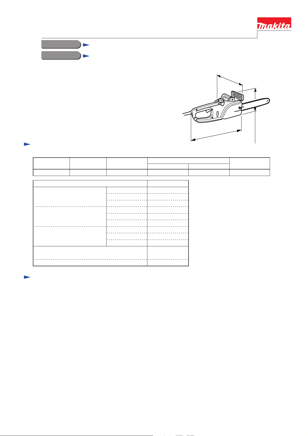
300mm, 350mm, 400mm chain saw
CONCEPTION AND MAIN APPLICATIONS
These models are home use chain saws that correspond to the functions
Specifications
Voltage (V) Current (A) Cycle (Hz)
220-240
Chain speed
7.0 50/60 1500 780 2000
Continuous Rating (W)
Input Output
800m/min.
221mm
(8-11/16")
410mm(16-1/8")
180mm(7-3/32")
Max.
Output(W)
Saw chain
Standard equipment
Chain cover
Universal wrench
--------------------------- 1 pc.
-------------------- 1 pc.
Type
Pitch
Gauge
90SG
3/8"
0.042"
Page 2
Repair
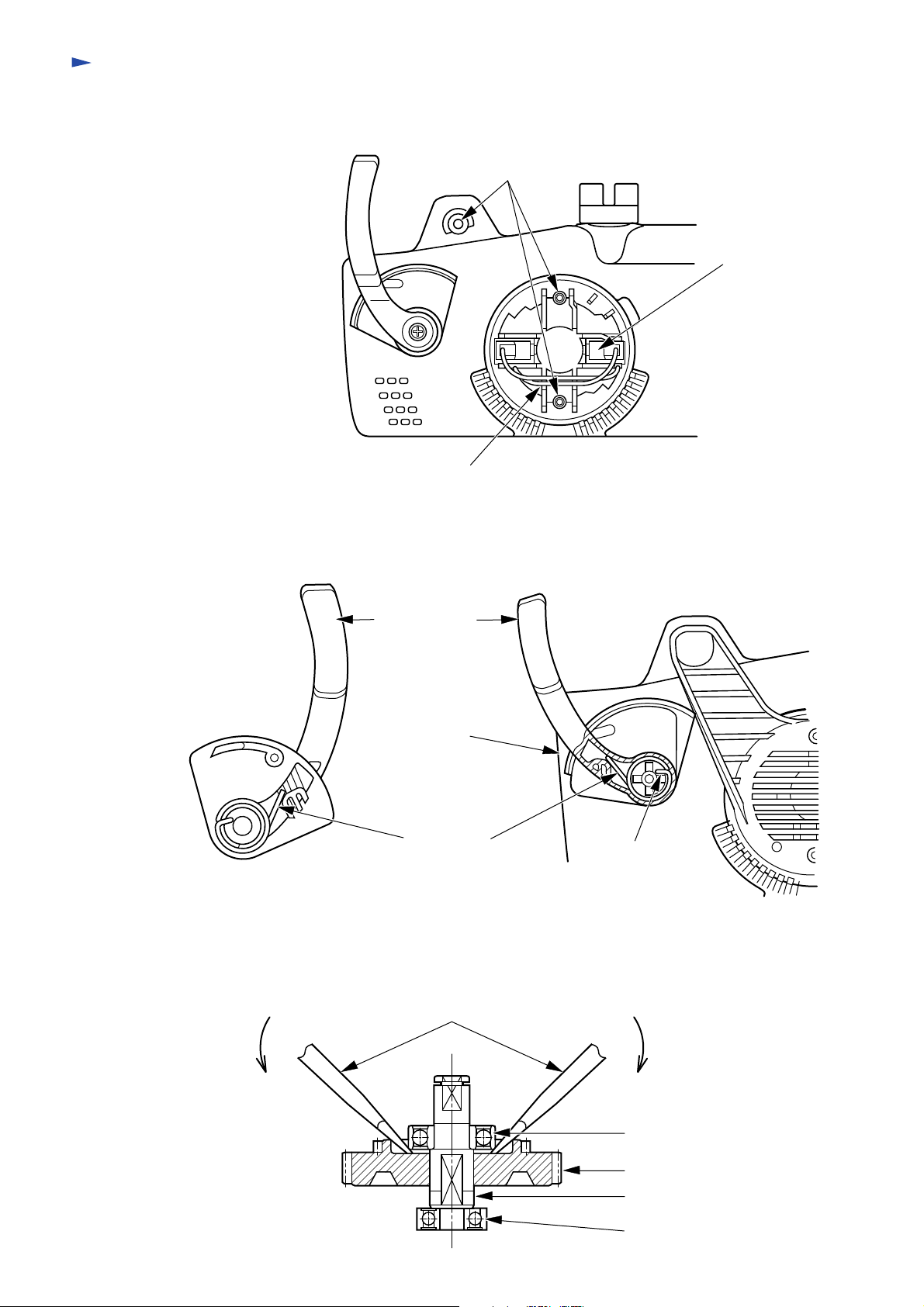
1. Replacement of carbon
1)
Loosen three tapping screws 4x18 that fix front handle and remove front handle to replace the carbon.
2)
Secure lead wires to the lead holder.
Tapping screw 4x18 (3 pcs.)
Carbon brush
Lead holders (4 locations)
2. Replacement of front hand guard
1)
Put down front hand guard forward and replace it while actuating a kick-back brake.
2)
Mount torsion spring 20 on the front hand guard as shown in the figure below.
3)
Mount the front hand guard to the housing L at an angle as shown below. At this time hook the torsion spring to the
boss of the housing L.
Front hand guard
Housing L
Torsion spring 20 Hook here
3. Replacement of bearing
Replace bearing #6001LLB by using two flat head screwdrivers as shown below.
Flat head screwdriver
Bearing #6001LLB
Spur gear 55
Spindle
Bearing #608ZZ
Page 3

4. Replacement of oil pump complete
1)
Loosen tapping screw 3.5x10 and remove holder.
2)
Remove oil pump complete together with oil bezel.
3)
Secure pipe 6 on the groove of the bearing holder and the pipe holder.
4)
Insert flat washer 5 between bearing holder and spur gear 39.
Tapping screw 3.5x10
Oil pump
complete
Oil bezel
Flat washer 5
Groove
Holder
Bearing holder
Pipe holder
Pipe 6
5. Replacement of armature
1)
Before replacement release kick-back brake by following the instruction manual.
2)
Remove carbon by following the procedures of "1. Replacement of carbon."
3)
When pulling out/putting on armature from/to bearing holder, hook a rod to the bearing holder and release the kickback brake.
4)
Use two flat head screwdrivers to replace the bearing #6000LLB.
Rod
Hook here
Bearing holder
Flat head screwdriver
#6000LLB
6. Replacement of brake band
1)
Release the brake as the same procedures as 5-1 above.
2)
Before replacing the brake band, insert rink plate complete to the brake band hole and mount it on the bearing holder.
3)
Confirm that the claws of the brake band and those of the brake ring are positioned as shown in the figure below.
Brake ring
Link plate complete
Brake band
Page 4

Wiring diagram
Orange
Power supply cord
P1
P2
Mains switch
Details of wiring
Sub-switch
1
4
Black
5
4
3
2
Noise
suppressor
Black
Brush holder
(Rear handle side)
Connect receptacle as shown in the figure.
Support complete
Black White
Brush holder
(Front handle side)
Receptacle
Receptacle
Fix lead wires by the lead holders.
Contain noise suppressor as shown in the figure.
Noise suppressor
 Loading...