

Page 1

GB
RT0700C
Trimmer Instruction Manual
F
Affleureuse Manuel d’instructions
D
Einhandfräse Betriebsanleitung
I
Rifilatore Istruzioni per l’uso
NL
Kantenfrees Gebruiksaanwijzing
E
Recortadora Manual de instrucciones
P
Tupia Manual de instruções
DK
Overfræser Brugsanvisning
GR Ρούτερ (κουρεπτικό) Οδηγίες χρήσεως
TR Şekil verme testeresi Kullanma kilavuzu
Page 2
7
1
2
3
4
5
6
11
12
14
89
12
11
10
13
12
34
5
2
Page 3
18
16
15
19
15
16
17
18
18
16
56
75
76
6
7
89
3
Page 4
10 11
31
30
19
33
29
32
19
31
24
23
24
25
26
15
27
10mm (3/8")
28
20
21
22
21
12 13
14 15
29
30
19
31
A
16 17
4
33
29
31
30
19
Page 5
18 19
41
35
36
37
38
34
33
19
20 21
22
39
40
15
42
43
23
5
Page 6
24 25
49
50
44
48
45
46
47
46
44
45
44
14
26 27
28 29
47
51
39
30 31
6
Page 7
43
60
58
59
43
57
52
54
55
52
56
21
52
53
33
32 34
35 36
37 38
54
7
Page 8
18
16
15
19
15
16
17
18
18
16
61
62
63
64
65
66
67
68
39
40
41
8
Page 9
A
70
29
69
31
29
30
19
42
43 44
71
31
72
19
45 46
9
Page 10

77
75
76
39
24
25
15
26
73
74
43
24
25
47 48
49
50 51
10
Page 11

52
22
78
11
Page 12

ENGLISH (Original instructions)
1 Bit protrusion
2Tool base
3Scale
4 Locking lever
5 Adjusting screw
6 Hex nut
7 Switch
8 OFF (O) side
9 ON ( I ) side
10 Speed adjusting dial
11 Tighten
12 Loosen
13 Hold
14 Shaft lock
15 Workpiece
16 Bit revolving direction
17 View from the top of the tool
18 Feed direction
19 Straight guide
20 Base protector
21 Screws
22 Screwdriver
23 Straight bit
24 Base
25 Templet
26 Distance (X)
27 Templet guide 10
28 Base protector
Explanation of general view
29 Bolt
30 Guide plate
31 Wing nut
32 Clamp screw (A)
33 Center hole
34 Nail
35 Clamp screw (A)
36 Adjusting screw
37 Clamp screw (B)
38 Trimmer guide
39 Bit
40 Guide roller
41 Clamping screws
42 Base protector
43 Screw
44 Pulley
45 Collet nut
46 Collet cone
47 Wrench
48 Belt
49 Locking lever
50 Offset base
51 Hex wrench
52 Offset base plate
53 Upper section of the offset base
54 Bar type grip (optional acces-
sory)
55 Grip attachment (optional
accessory)
56 Trimmer base
57 Knob type grip
58 Plunge base
59 Grip
60 Knob
61 Adjusting knob
62 Lock lever
63 Depth pointer
64 Stopper pole setting nut
65 Fast-feed button
66 Stopper pole
67 Stopper block
68 Adjusting bolt
69 Guide holder
70 Wing bolts
71 Guide bar
72 Wing bolt
73 Outside diameter of the templet
guide
74 Templet guide
75 Dust nozzle
76 Thumb screw
77 Limit mark
78 Brush holder cap
SPECIFICATIONS
Model RT0700C
Collet chuck capacity.................6 mm, 8 mm, 1/4” or 3/8”
No load speed (min
Overall length ...................................................... 200 mm
Net weight .............................................................. 1.8 kg
Safety class ............................................................. /II
• Due to the continuing program of research and development, the specifications herein are subject to change
without prior notice.
• Specifications may differ from country to country.
• Weight according to EPTA-Procedure 01/2003
Intended use
The tool is intended for flush trimming and profiling of
-1
) ............................ 10,000 – 30,000
ENE010-1
wood, plastic and similar materials.
ENF002-1
Power supply
The tool should be connected only to a power supply of
the same voltage as indicated on the nameplate, and can
only be operated on single-phase AC supply. They are
double-insulated in accordance with European Standard
and can, therefore, also be used from sockets without
earth wire.
12
GEA010-1
General Power Tool Safety Warnings
WARNING Read all safety warnings and all
instructions. Failure to follow the warnings and
instructions may result in electric shock, fire and/or
serious injury.
Save all warnings and instructions for future reference.
GEB019-4
TRIMMER SAFETY WARNINGS
1. Hold power tool by insulated gripping surfaces,
because the cutter may contact its own cord.
Cutting a “live” wire may make exposed metal parts
of the power tool “live” and shock the operator.
2. Use clamps or another practical way to secure
and support the workpiece to a stable platform.
Holding the work by hand or against your body
leaves it unstable and may lead to loss of control.
3. Wear hearing protection during extended period
of operation.
4. Handle the bits very carefully.
5. Check the bit carefully for cracks or damage
before operation.
Replace cracked or damaged bit immediately.
6. Avoid cutting nails. Inspect for and remove all
nails from the workpiece before operation.
7. Hold the tool firmly.
8. Keep hands away from rotating parts.
9. Make sure the bit is not contacting the workpiece before the switch is turned on.
Page 13

10. Before using the tool on an actual workpiece, let
it run for a while.
Watch for vibration or wobbling that could indicate improperly installed bit.
11. Be careful of the bit rotating direction and the
feed direction.
12. Do not leave the tool running. Operate the tool
only when hand-held.
13. Always switch off and wait for the bit to come to
a complete stop before removing the tool from
workpiece.
14. Do not touch the bit immediately after operation;
it may be extremely hot and could burn your
skin.
15. Do not smear the tool base carelessly with thinner, gasoline, oil or the like.
They may cause cracks in the tool base.
16. Use bits of the correct shank diameter suitable
for the speed of the tool.
17. Some material contains chemicals which may be
toxic. Take caution to prevent dust inhalation
and skin contact. Follow material supplier safety
data.
18. Always use the correct dust mask/respirator for
the material and application you are working
with.
SAVE THESE INSTRUCTIONS.
WARNING:
DO NOT let comfort or familiarity with product
(gained from repeated use) replace strict adherence
to safety rules for the subject product. MISUSE or
failure to follow the safety rules stated in this instruction manual may cause serious personal injury.
FUNCTIONAL DESCRIPTION
CAUTION:
• Always be sure that the tool is switched off and
unplugged before adjusting or checking function on the
tool.
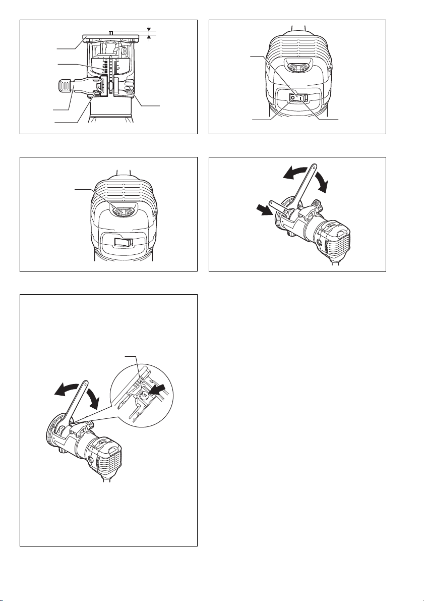
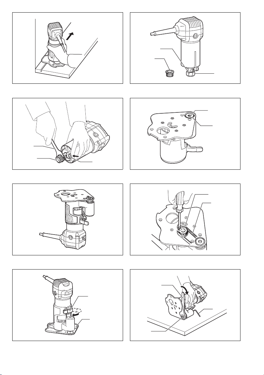
Adjusting bit protrusion (Fig. 1)
To adjust the bit protrusion, loosen the locking lever and
move the tool base up or down as desired by turning the
adjusting screw. After adjusting, tighten the locking lever
firmly to secure the tool base.
NOTE:
• When the tool is not secured even if the locking lever is
tightened, tighten the hex nut and then tighten the locking lever.
Switch action (Fig. 2)
CAUTION:
• Before plugging in the tool, always check to see that
the tool is switched off.
To start the tool, press the “ON ( I )” side of the switch. To
stop the tool, press the “OFF (O)” side of the switch.
Electronic function
The tool equipped with electronic function are easy to
operate because of the following features.
Constant speed control
Electronic speed control for obtaining constant speed.
Possible to get fine finish, because the rotating speed is
kept constant even under load condition.
Soft start
Soft-start feature minimizes start-up shock, and makes
the tool start smoothly.
Speed adjusting dial (Fig. 3)
The tool speed can be changed by turning the speed
adjusting dial to a given number setting from 1 to 6.
Higher speed is obtained when the dial is turned in the
direction of number 6. And lower speed is obtained when
it is turned in the direction of number 1.
This allows the ideal speed to be selected for optimum
material processing, i.e. the speed can be correctly
adjusted to suit the material and bit diameter.
Refer to the table for the relationship between the number settings on the dial and the approximate tool speed.
Number min
1 10,000
2 12,000
3 17,000
4 22,000
5 27,000
6 30,000
CAUTION:
• If the tool is operated continuously at low speeds for a
long time, the motor will get overloaded, resulting in
tool malfunction.
• The speed adjusting dial can be turned only as far as 6
and back to 1. Do not force it past 6 or 1, or the speed
adjusting function may no longer work.
-1
ASSEMBLY
CAUTION:
• Always be sure that the tool is switched off and
unplugged before carrying out any work on the tool.
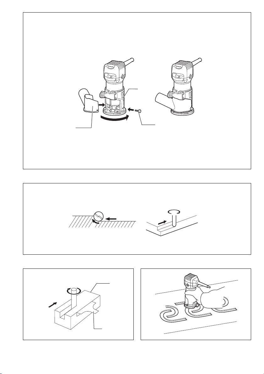
Installing or removing trimmer bit (Fig. 4 & 5)
CAUTION:
• Do not tighten the collet nut without inserting a bit, or
the collet cone will break.
• Use only the wrenches provided with the tool.
Insert the bit all the way into the collet cone and tighten
the collet nut securely with the two wrenches or by pressing the shaft lock and using the provided wrench.
To remove the bit, follow the installation procedure in
reverse.
13
Page 14

OPERATION
For the trimmer base (Fig. 6)
WARNING:
• Before using the tool with the trimmer base, always
install the dust nozzle on the trimmer base.
Set the tool base on the workpiece to be cut without the
bit making any contact. Then turn the tool on and wait
until the bit attains full speed. Move the tool forward over
the workpiece surface, keeping the tool base flush and
advancing smoothly until the cutting is complete.
When doing edge cutting, the workpiece surface should
be on the left side of the bit in the feed direction. (Fig. 7)
NOTE:
• Moving the tool forward too fast may cause a poor
quality of cut, or damage to the bit or motor. Moving the
tool forward too slowly may burn and mar the cut. The
proper feed rate will depend on the bit size, the kind of
workpiece and depth of cut. Before beginning the cut
on the actual workpiece, it is advisable to make a sample cut on a piece of scrap lumber. This will show
exactly how the cut will look as well as enable you to
check dimensions.
• When using the trimmer shoe, the straight guide or the
trimmer guide, be sure to keep it on the right side in the
feed direction. This will help to keep it flush with the
side of the workpiece. (Fig. 8)
CAUTION:
• Since excessive cutting may cause overload of the
motor or difficulty in controlling the tool, the depth of cut
should not be more than 3 mm at a pass when cutting
grooves. When you wish to cut grooves more than
3 mm deep, make several passes with progressively
deeper bit settings.
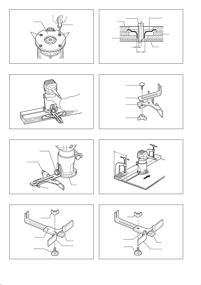
Templet guide
The templet guide provides a sleeve through which the
bit passes, allowing use of the trimmer with templet patterns. (Fig. 9)
Loosen the screws and remove the base protector. Place
the templet guide on the base and replace the base protector. Then secure the base protector by tightening the
screws. (Fig. 10)
Secure the templet to the workpiece. Place the tool on
the templet and move the tool with the templet guide sliding along the side of the templet. (Fig. 11)
NOTE:
• The workpiece will be cut a slightly different size from
the templet. Allow for the distance (X) between the
router bit and the outside of the templet guide. The distance (X) can be calculated by using the following
equation:
Distance (X) = (outside diameter of the templet guide –
router bit diameter) / 2
Straight guide (Accessory)
The straight guide is effectively used for straight cuts
when chamfering or grooving. (Fig. 12)
Attach the guide plate to the straight guide with the bolt
and the wing nut. (Fig. 13)
Attach the straight guide with the clamp screw (A).
Loosen the wing nut on the straight guide and adjust the
distance between the bit and the straight guide. At the
desired distance, tighten the wing nut securely.
When cutting, move the tool with the straight guide flush
with the side of the workpiece. (Fig. 14)
If the distance (A) between the side of the workpiece and
the cutting position is too wide for the straight guide, or if
the side of the workpiece is not straight, the straight
guide cannot be used. In this case, firmly clamp a
straight board to the workpiece and use it as a guide
against the trimmer base. Feed the tool in the direction of
the arrow. (Fig. 15)
Circular work
Circular work may be accomplished if you assemble the
straight guide and guide plate as shown in Fig. 16 or 17.
Min. and max. radius of circles to be cut (distance
between the centre of circle and the centre of bit) are as
follows:
Min.: 70 mm
Max.: 221 mm
Fig. 16 for cutting circles between 70 mm and 121 mm in
radius.
Fig. 17 for cutting circles between 121 mm and 221 mm
in radius.
NOTE:
• Circles between 172 mm and 186 mm in radius cannot
be cut using this guide.
Align the centre hole in the straight guide with the centre
of the circle to be cut. Drive a nail less than 6 mm in
diameter into the centre hole to secure the straight guide.
Pivot the tool around the nail in clockwise direction.
(Fig. 18)
Trimmer guide (optional accessory)
Trimming, curved cuts in veneers for furniture and the
like can be done easily with the trimmer guide. The guide
roller rides the curve and assures a fine cut. (Fig. 19)
Install the trimmer guide on the tool base with the clamp
screw (A). Loosen the clamp screw (B) and adjust the
distance between the bit and the trimmer guide by turning the adjusting screw (1 mm per turn). At the desired
distance, tighten the clamp screw (B) to secure the trimmer guide in place. (Fig. 20)
When cutting, move the tool with the guide roller riding
the side of the workpiece. (Fig. 21)
Tilt base (optional accessory)
Tilt base (optional accessory) is convenient for chamfering. (Fig. 22)
Place the tool onto the tilt base and close the locking
lever at the desired protrusion of the bit. For desired
angle, tighten the clamping screws on its sides.
Firmly clamp a straight board to the workpiece and use it
as a guide against the trimmer base. Feed the tool in the
direction of the arrow.
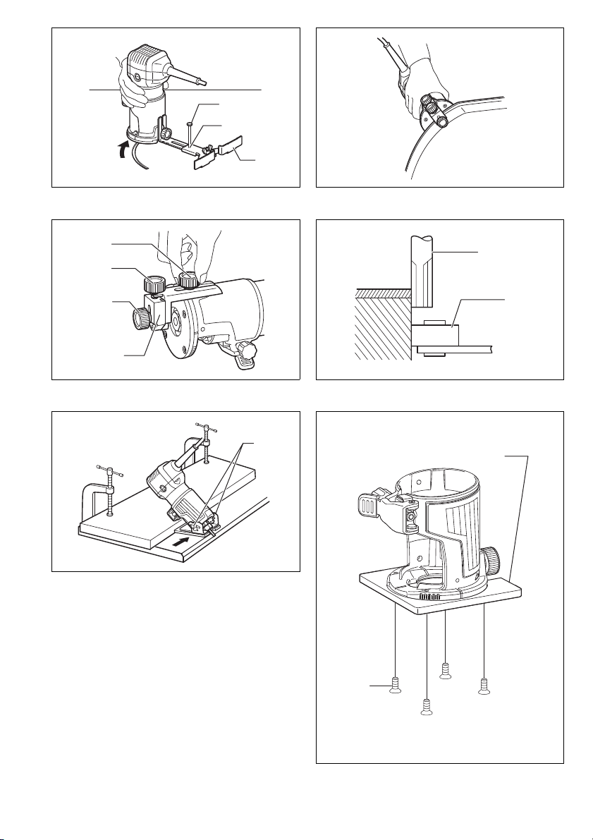
Base protector removed from the tilt base (optional
accessory)
Mounting the base protector which has been removed
from the tilt base on the trimmer base allows the change
of the trimmer base from the round base to a square
base.
For another application, remove the base protector from
the tilt base by loosening and removing four screws.
(Fig. 23)
And then mount the base protector on the trimmer base.
14
Page 15

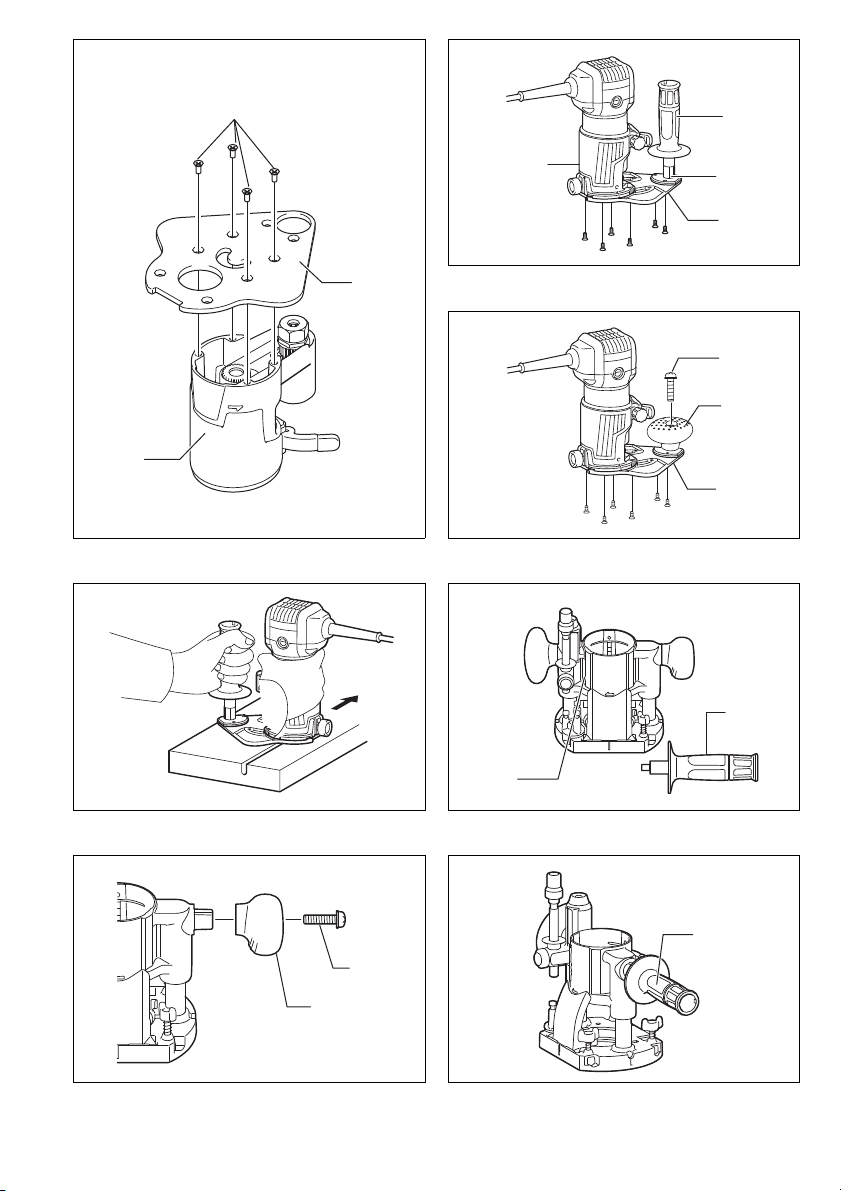
Offset base (optional accessory)
(1) Offset base (optional accessory) is convenient for
work in a tight area such as a corner. (Fig. 24 & 25)
Before installing the tool on the offset base, remove the
collet nut and collet cone by loosening the collet nut.
(Fig. 26)
Install the pulley on the tool by pressing the shaft lock
and firmly tightening the pulley with a wrench. (Fig. 27)
Place the collet cone and screw the collet nut on the offset base as shown in the figure. (Fig. 28)
Mount the tool on the offset base. (Fig. 29)
Put an end of the belt over the pulley using a screwdriver
and make sure that its entire belt width fits over the pulley
completely. (Fig. 30)
Secure it with a locking lever on the offset base. (Fig. 31)
To install the bit, fall the tool with the offset base on its
side. Insert the hex wrench into the hole in the offset
base.
With the hex wrench held in that position, insert the bit
into the collet cone on the shaft of the offset base from
the opposite side and tighten the collet nut firmly with a
wrench.
To remove the bit at replacement, follow the installation
procedure in reverse.
(2) Offset base (optional accessory) can also be used
with a trimmer base and a grip attachment (optional
accessory) for more stability. (Fig. 32)
Loosen the screws and remove the upper section from
the offset base. Put aside the upper section of the offset
base. (Fig. 33)
Mount the trimmer base with four screws and the grip
attachment (optional accessory) with two screws on the
offset base plate.
Screw a bar type grip (optional accessory) onto the grip
attachment. (Fig. 34)
In another way of use, the knob type grip which is
removed from a plunge base (optional accessory) can be
installed on the grip attachment. To install the knob type
grip, place it on the grip attachment and secure it with a
screw. (Fig. 35)
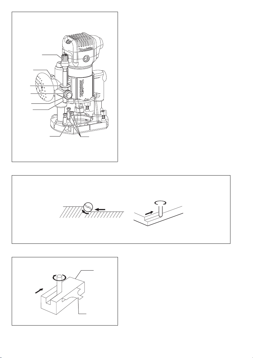
When using as a router only with a plunge base
(optional accessory)
CAUTION:
• When using as a router, hold the tool firmly with both
hands.
To use the tool as a router, install the tool on a plunge
base (optional accessory) by pressing it down fully.
(Fig. 36)
Either knob type grip or bar type grip (optional accessory) can be used according to your work. (Fig. 37)
To use the bar type grip (optional accessory), loosen the
screw and remove the knob type grip. (Fig. 38)
And then screw the bar type grip on the base.
Adjusting the depth of cut when using the plunge
base (optional accessory)
Place the tool on a flat surface. Loosen the lock lever and
lower the tool body until the bit just touches the flat surface. Tighten the lock lever to lock the tool body. (Fig. 39)
Turn the stopper pole setting nut counterclockwise.
Lower the stopper pole until it makes contact with the
adjusting bolt. Align the depth pointer with the “0” graduation. The depth of cut is indicated on the scale by the
depth pointer.
While pressing the fast-feed button, raise the stopper
pole until the desired depth of cut is obtained. Minute
depth adjustments can be obtained by turning the adjusting knob (1 mm per turn).
By turning the stopper pole setting nut clockwise, you
can fasten the stopper pole firmly.
Now, your predetermined depth of cut can be obtained by
loosening the lock lever and then lowering the tool body
until the stopper pole makes contact with the adjusting
hex bolt of the stopper block.
Always firmly hold the tool by both grip during operation.
Set the tool base on the workpiece to be cut without the
bit making any contact. Then turn the tool on and wait
until the bit attains full speed. Lower the tool body and
move the tool forward over the workpiece surface, keeping the tool base flush and advancing smoothly until the
cutting is complete.
When doing edge cutting, the workpiece surface should
be on the left side of the bit in the feed direction. (Fig. 40)
NOTE:
• Moving the tool forward too fast may cause a poor
quality of cut, or damage to the bit or motor. Moving the
tool forward too slowly may burn and mar the cut. The
proper feed rate will depend on the bit size, the kind of
workpiece and depth of cut. Before beginning the cut
on the actual workpiece, it is advisable to make a sample cut on a piece of scrap lumber. This will show
exactly how the cut will look as well as enable you to
check dimensions.
• When using the straight guide, be sure to install it on
the right side in the feed direction. This will help to keep
it flush with the side of the workpiece. (Fig. 41)
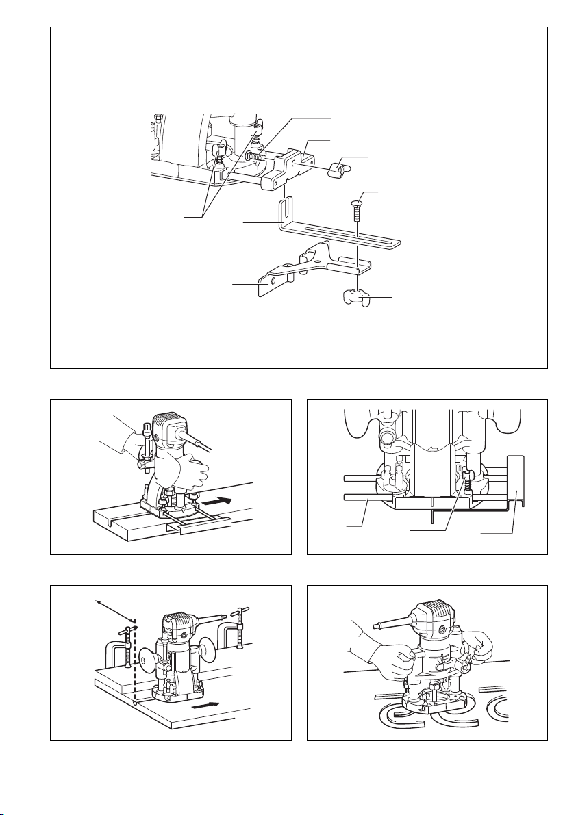
Straight guide when using as a router (needed to
use with guide holder (optional accessory))
The straight guide is effectively used for straight cuts
when chamfering or grooving. (Fig. 42)
Install the straight guide on the guide holder (optional
accessory) with the wing nut.
Insert the guide holder into the holes in the plunge base
and tighten the wing bolts. To adjust the distance
between the bit and the straight guide, loosen the wing
nut. At the desired distance, tighten the wing nut to
secure the straight guide in place.
Straight guide (optional accessory)
The straight guide is effectively used for straight cuts
when chamfering or grooving. (Fig. 43 & 44)
To install the straight guide, insert the guide bars into the
holes in the plunge base. Adjust the distance between
the bit and the straight guide. At the desired distance,
tighten the wing bolts to secure the straight guide in
place.
When cutting, move the tool with the straight guide flush
with the side of the workpiece. (Fig. 45)
15
Page 16

If the distance (A) between the side of the workpiece and
the cutting position is too wide for the straight guide, or if
the side of the workpiece is not straight, the straight
guide cannot be used. In this case, firmly clamp a
straight board to the workpiece and use it as a guide
against the router base. Feed the tool in the direction of
the arrow.
Templet guide (Accessory)
The templet guide provides a sleeve through which the
bit passes, allowing use of the tool with templet patterns.
(Fig. 46)
To install the templet guide, loosen the screws on the tool
base, insert the templet guide and then tighten the
screws. (Fig. 47)
Secure the templet to the workpiece. Place the tool on
the templet and move the tool with the templet guide sliding along the side of the templet. (Fig. 48)
NOTE:
• The workpiece will be cut a slightly different size from
the templet. Allow for the distance (X) between the bit
and the outside of the templet guide.
The distance (X) can be calculated by using the following equation:
Distance (X) = (outside diameter of the templet guide –
bit diameter) / 2
Dust nozzle sets
For the trimmer base (Fig. 6)
For the plunge base (optional accessory) (Fig. 49)
Use the dust nozzle for dust extraction. Install the dust
nozzle on the tool base using the thumb screw so that
protrusion on the dust nozzle fit to the notch in the tool
base.
Then connect a vacuum cleaner to the dust nozzle.
(Fig. 50)
MAINTENANCE
CAUTION:
• Always be sure that the tool is switched off and
unplugged before attempting to perform inspection or
maintenance.
• Never use gasoline, benzine, thinner, alcohol or the
like. Discoloration, deformation or cracks may result.
Replacing carbon brushes
Remove and check the carbon brushes regularly.
Replace when they wear down to the limit mark. Keep
the carbon brushes clean and free to slip in the holders.
Both carbon brushes should be replaced at the same
time. Use only identical carbon brushes. (Fig. 51)
Use a screwdriver to remove the brush holder caps. Take
out the worn carbon brushes, insert the new ones and
secure the brush holder caps. (Fig. 52)
To maintain product SAFETY and RELIABILITY, repairs,
any other maintenance or adjustment should be performed by Makita Authorized Service Centers, always
using Makita replacement parts.
OPTIONAL ACCESSORIES
CAUTION:
• These accessories or attachments are recommended
for use with your Makita tool specified in this manual.
The use of any other accessories or attachments might
present a risk of injury to persons. Only use accessory
or attachment for its stated purpose.
If you need any assistance for more details regarding
these accessories, ask your local Makita Service Center.
• Straight & groove forming bits
• Edge forming bits
• Laminate trimming bits
• Straight guide assembly
• Trimmer guide assembly
• Trimmer base assembly
• Tilt base assembly
• Plunge base assembly
• Offset base assembly
• Templet guide
• Collet cone 6 mm
• Collet cone 6.35 mm (1/4")
• Collet cone 8 mm
• Collet cone 9.53 mm (3/8")
• Wrench 13
• Wrench 22
NOTE:
• Some items in the list may be included in the tool package as standard accessories. They may differ from
country to country.
ENG905-1
Noise
The typical A-weighted noise level determined according
to EN60745:
Sound pressure level (L
Sound power level (L
Uncertainty (K): 3 dB (A)
Wear ear protection
Vibration
The vibration total value (tri-axial vector sum) determined
according to EN60745:
Work mode : rotation without load
Vibration emission (a
Uncertainty (K) : 1.5 m/s
Work mode : cutting grooves in MDF
Vibration emission (a
Uncertainty (K) : 1.5 m/s
• The declared vibration emission value has been measured in accordance with the standard test method and
may be used for comparing one tool with another.
• The declared vibration emission value may also be
used in a preliminary assessment of exposure.
WARNING:
• The vibration emission during actual use of the power
tool can differ from the declared emission value
depending on the ways in which the tool is used.
• Be sure to identify safety measures to protect the operator that are based on an estimation of exposure in the
actual conditions of use (taking account of all parts of
the operating cycle such as the times when the tool is
switched off and when it is running idle in addition to
the trigger time).
): 82 dB (A)
pA
): 93 dB (A)
WA
) : 2.5 m/s2 or less
h
2
) : 3.5 m/s
h
2
2
ENG900-1
ENG901-1
16
Page 17

ENH101-14
For European countries only
EC Declaration of Conformity
We Makita Corporation as the responsible manufacturer declare that the following Makita machine(s):
Designation of Machine: Trimmer
Model No./ Type: RT0700C
are of series production and
Conforms to the following European Directives:
2006/42/EC
And are manufactured in accordance with the following
standards or standardised documents:
EN60745
The technical documentation is kept by our authorized
representative in Europe who is:
Makita International Europe Ltd.
Michigan Drive, Tongwell,
Milton Keynes, MK15 8JD, England
14.10.2010
Tomoyasu Kato
Director
Makita Corporation
3-11-8, Sumiyoshi-cho,
Anjo, Aichi, JAPAN
17
Page 18

NEDERLANDS (Originele instructies)
1 Gewenste freesdiepte
2 Zoolplaat gereedschap
3 Schaal
4 Klemhendel
5 Afstelschroef
6 Zeskantmoer
7 Schakelaar
8 UIT (O) kant
9AAN ( I ) kant
10 Snelheidsregelknop
11 Losdraaien
12 Vastdraaien
13 Vasthouden
14 Schachtklem
15 Werkstuk
16 Rotatierichting van het frees
17 Van bovenaf gezien
18 Trimrichting
19 Rechte geleider
20 Zoolplaatbeschermer
21 Schroef
22 Schroevendraaier
23 Rechte frees
24 Zoolplaat
25 Sjabloon
26 Afstand (X)
27 Sjabloongeleider 10
28 Zoolplaatbeschermer
Verklaring van algemene gegevens
29 Bout
30 Geleideplaat
31 Vleugelmoer
32 Klampschroef (A)
33 Middengaatje
34 Spijker
35 Klampschroef (A)
36 Afstelschroef
37 Klampschroef (B)
38 Trimgeleider
39 Frees
40 Rol van geleider
41 Klemschroeven
42 Zoolplaatbeschermer
43 Schroef
44 Poelie
45 Klembusmoer
46 Klembus
47 Sleutel
48 Aandrijfriem
49 Klemhendel
50 Afstandsvoet
51 Inbussleutel
52 Afstandsvoetplaat
53 Bovenste deel van de
afstandsvoet
54 Staafvormige handgreep
(optionele accessoire)
55 Handgreepbevestigingsstuk
(optionele accessoire)
56 Trimvoet
57 Knopvormige handgreep
58 Verdiepvoet
59 Handgreep
60 Knop
61 Afstelknop
62 Klemhendel
63 Dieptewijzer
64 Stopstang-instelmoer
65 Sneldoorvoerknop
66 Stopstang
67 Stopblok
68 Afstelbout
69 Geleidehouder
70 Vleugelbouten
71 Geleidestaaf
72 Vleugelbout
73 Buitendiameter van de
sjabloongeleider
74 Sjabloongeleider
75 Stofmondstuk
76 Duimschroef
77 Limiet
78 Kap van koolborstelhouder
TECHNISCHE GEGEVENS
Model RT0700C
Capaciteit klembus ....................6 mm, 8 mm, 1/4” of 3/8”
Toerental onbelast (min
Totale lengte ........................................................ 200 mm
Netto gewicht ......................................................... 1,8 kg
Veiligheidsklasse..................................................... /II
• In verband met ononderbroken research en ontwikkeling behouden wij ons het recht voor bovenstaande
technische gegevens te wijzigen zonder voorafgaande
kennisgeving.
• De technische gegevens kunnen van land tot land verschillen.
• Gewicht volgens de EPTA-procedure 01/2003
Doeleinden van gebruik
Dit gereedschap is bedoeld voor het gelijk afwerken en
voor het aanbrengen van profielen in hout, kunststof en
-1
) ...................... 10 000 – 30 000
ENE010-1
soortgelijke materialen.
ENF002-1
Stroomvoorziening
Het gereedschap mag alleen worden aangesloten op
een stroombron van hetzelfde voltage als aangegeven
op de naamplaat, en kan alleen op enkel-fase wisselstroom worden gebruikt. Het gereedschap is dubbelgeïsoleerd volgens de Europese standaard en kan derhalve ook op een niet-geaard stopcontact worden aangesloten.
GEA010-1
Algemene veiligheidswaarschuwingen voor
elektrisch gereedschap
WAARSCHUWING! Lees alle veiligheidswaar-
schuwingen en alle instructies. Het niet volgen van de
waarschuwingen en instructies kan leiden tot elektrische
schokken, brand en/of ernstig letsel.
Bewaar alle waarschuwingen en instructies om in de
toekomst te kunnen raadplegen.
GEB019-4
VEILIGHEIDSWAARSCHUWINGEN SPECIFIEK
VOOR EEN KANTENFREES
1. Houd elektrisch gereedschap vast aan de geïsoleerde handgrepen, want het risico bestaat dat
het snijvlak het snoer raakt. Als een draad die
onder stroom staat wordt ingesneden, komen de
metalen delen van het gereedschap ook onder
stroom te staan en kunt u een gevaarlijke schok krijgen.
2. Gebruik klemmen of een andere praktische
methode om het werkstuk op een stabiele ondergrond te bevestigen en teondersteunen. Als u het
werkstuk in uw hand of tegen uw lichaam geklemd
houdt, is het onvoldoende stabiel en kunt u de controle erover verliezen.
3. Gebruik een oorbescherming, wanneer u lange
tijd met dit gereedschap denkt te werken.
4. Wees voorzichtig met de frees.
36
Page 19

5. Controleer de frees op barsten of beschadiging,
alvorens het gereedschap in te schakelen en
vervang onmiddellijk als de frees is gebarsten of
beschadigd.
6. Zorg dat de frees niet in contact komt met spijkers enz. Verwijder derhalve alvorens met trimmen te beginnen eventuele spijkers en
dergelijke van het werkstuk.
7. Houd het gereedschap stevig vast.
8. Houd uw handen uit de buurt van de roterende
delen.
9. Zorg dat de frees niet in contact is met het werkstuk wanneer u het gereedschap inschakelt.
10. Laat het gereedschap draaien, alvorens het
werkstuk te trimmen.
Controleer of er trillingen en/of schommelingen
zijn, die op een verkeerd geïnstalleerde frees
kunnen wijzen.
11. Zorg dat de rotatierichting overeenkomt met de
trimrichting.
12. Schakel het gereedschap onmiddellijk uit, als u
het niet meer gebruikt. Schakel het gereedschap
alleen in, als u het in handen houdt.
13. Schakel het gereedschap uit en wacht tot het
helemaal tot stilstand is gekomen, alvorens het
van het werkstuk te verwijderen.
14. Raak de frees onmiddellijk na het trimmen niet aan;
aangezien het nog gloeiend heet is en derhalve
brandwonden kan veroorzaken.
15. Wees voorzichtig en veeg het voetstuk van het
gereedschap niet af met verfverdunner, benzine,
olie of iets dergelijks, aangezien er anders barsten in kunnen komen.
16. Gebruik frezen van de juiste schachtdiameter,
geschikt voor de snelheid van dit gereedschap.
17. Sommige materialen bevatten chemische stoffen
die vergiftig kunnen zijn. Vermijd inademing van
stof en contact met de huid. Volg de veiligheidsinstructies van de leverancier van het materiaal.
18. Gebruik altijd het juiste stofmasker/ademhalingsapparaat voor het materiaal en de toepassing waarmee u werkt.
BEWAAR DEZE VOORSCHRIFTEN.
WAARSCHUWING:
Laat u NIET misleiden door een vals gevoel van comfort en bekendheid met het gereedschap (na veelvuldig gebruik) en neem alle veiligheidsvoorschriften
van het betreffende product altijd strikt in acht. VERKEERD GEBRUIK of het niet naleven van de veiligheidsvoorschriften in deze gebruiksaanwijzing kan
leiden tot ernstige verwondingen.
BESCHRIJVING VAN DE FUNCTIES
LET OP:
• Zorg altijd dat het gereedschap is uitgeschakeld en de
stekker uit het stopcontact is verwijderd alvorens de
functies op het gereedschap te controleren of af te stellen.
De snijdiepte instellen (Fig. 1)
Om de snijdiepte in te stellen, draait u de klemhendel los
en beweegt u de zoolplaat omhoog of omlaag, al naar
gelang gewenst, door de afstelschroef te draaien. Na het
instellen draait u de klemhendel stevig aan om de zoolplaat goed vast te zetten.
OPMERKING:
• Wanneer het gereedschap ook na aandraaien van de
klemhendel niet goed vast zit, draait u eerst de zeskantmoer aan en dan draait u de klemhendel vast.
In- en uitschakelen (Fig. 2)
LET OP:
• Let vooral op dat het gereedschap staat uitgeschakeld,
voordat u de stekker in het stopcontact steekt.
Om het gereedschap in te schakelen, drukt u op de “AAN
( I )” kant van de schakelaar. Om het gereedschap uit te
schakelen, drukt u op de “UIT (O)” kant van de
schakelaar.
Elektronische functies
Het gereedschap is voorzien van elektronische functies
die de bedeining vergemakkelijken, in de volgende
opzichten.
Constante snelheidsstabilisatie
Deze elektronische snelheidsregeling zorgt dat de
snelheid constant blijft. Dit maakt een preciese afwerking
mogelijk, omdat de snelheid constant blijft ongeacht de
belasting.
Soepele start
De soepele-startfunctie voorkomt een schokbeweging bij
het inschakelen, zodat u vanaf het begin nauwkeurig
kunt werken.
Snelheidsregelknop (Fig. 3)
U kunt de snelheid naar wens kiezen door de
snelheidsregelknop in te stellen op een numerieke
waarde van 1 tot 6.
U kiest een hogere snelheid door de knop in de richting
van de 6 te draaien. Voor een lagere snelheid draait u de
knop in de richting van de 1.
Zo kunt u precies de geschikte snelheid kiezen voor het
werk, m.a.w. u kiest de snelheid aan de hand van het
materiaal en de freesdiameter.
Zie de tabel voor de verhouding tussen de genummerde
stand van de knop en de snelheid van het gereedschap,
bij benadering.
Nummer min
1 10 000
2 12 000
3 17 000
4 22 000
5 27 000
6 30 000
LET OP:
• Als het gereedschap langdurig achtereen op een laag
toerental blijft draaien, kan de motor overbelast raken,
met kans op defecten.
• De snelheidsregelknop kan alleen maar tot 6 gedraaid
worden, en terug naar 1. Probeer niet de knop voorbij
de 6 of de 1 te draaien, want dan zal de
snelheidsregeling falen.
-1
37
Page 20

INEENZETTEN
LET OP:
• Zorg altijd dat het gereedschap is uitgeschakeld en de
stekker uit het stopcontact is verwijderd alvorens enig
werk aan het gereedschap uit te voeren.
Inzetten of verwijderen van de freeskop
(Fig. 4 en 5)
LET OP:
• Draai de klembusmoer niet aan zonder frees in de
klembus, want dan kan de klembus breken.
• Gebruik uitsluitend de steeksleutels die met het
gereedschap zijn bijgeleverd.
Steek de frees helemaal in de klembus en draai de klembus stevig aan met twee sleutels of door indrukken van
de schachtklem en gebruik van de bijgeleverde sleutel.
Voor het verwijderen van de frees, volgt u de procedure
voor het inzetten in omgekeerde volgorde.
BEDIENING
Voor de zoolplaat (Fig. 6)
WAARSCHUWING:
• Voordat u het gereedschap gaat gebruiken met de
zoolplaat, installeert u altijd eerst het stofmondstuk op
de zoolplaat.
Zet de zoolplaat op het te trimmen werkstuk. De frees
mag er echter nog niet mee in contact komen. Schakel
het gereedschap vervolgens in en wacht totdat het op
volle toeren is gekomen. Hierna beweegt u het gereedschap rustig over het werkstuk, ervoorzorgend dat de
zoolplaat altijd op het werkstuk blijft rusten, totdat het
trimmen voltooid is.
Wanneer u de rand van het werkstuk wilt bewerken,
plaatst u het werkstuk links, zoals in de onderstaande
illustratie. (Fig. 7)
OPMERKING:
• Wanneer u het gereedschap te snel voortbeweegt, kan
het resultaat onbevredigend zijn, of kan de frees of de
motor beschadiging oplopen. Wanneer u echter het
gereedschap te langzaam beweegt, krijgt u een lelijk
freesoppervlak of kan er op het freesoppervlakt een
brandvlek komen. Hoe snel u het best het gereedschap
kunt voortbewegen, hangt af van de freesafmetingen,
het materiaal en de snijdiepte. Het verdient derhalve
aanbeveling een proef te doen, alvorens u het werkstuk
bewerkt. U kunt dan zien hoe het freesoppervlakte eruit
zal zien en de afmetingen controleren.
• Wanneer U de trimschoen, de rechte geleider of de
trimgeleider gebruikt, dient U deze rechts van de snijrichting te houden, zodat deze volledig op het werkstuk
kan rusten. (Fig. 8)
LET OP:
• Aangezien door een overmatige trimdiepte de motor
overbelast kan raken en u moeite krijgt het gereedschap onder controle te houden, mag dus voor het snijden van groeven de trimdiepte per bewerking niet meer
dan 3 mm bedragen. Wilt u de groef dieper hebben dan
dient u de freeskop telkens verder uit te laten steken
(telkens niet meer dan 3 mm) en de bewerking zonodig
herhalen tot de groef de gewenste diepte heeft.
Sjabloongeleider
De sjabloongeleider is voorzien van een huls, waardoor
de freeskop steekt, zodat u met het gereedschap de
patronen van de sjabloon nauwkeurig kunt volgen.
(Fig. 9)
Draai de schroeven los en verwijder de zoolplaatbeschermer. Plaats de sjabloongeleider op de zoolplaat, en
plaats de zoolplaatbeschermer terug op z’n oorspronkelijke plaats. Zet vervolgens de zoolplaatbeschermer met
de schroeven vast. (Fig. 10)
Zet de sjabloon vast op het werkstuk. Plaats daarna het
gereedschap op de sjabloon en beweeg het zo voort dat
de sjabloongeleider de patronen van de sjabloon volgt.
(Fig. 11)
OPMERKING:
• De uitgesneden patronen in het werkstuk kunnen iets
andere afmetingen hebben dan die van de sjabloon.
Dit komt vanwege de afstand (X) tussen de freeskop
en de buitenkant van de sjabloongeleider.
Deze afstand (X) kunt u als volgt berekenen:
Afstand (X) = (buitendiameter van de sjabloongeleider
– freeskopdiameter) / 2
Rechte geleider (accessoire)
De rechte geleider zorgt voor een keurig rechte snede tijdens het profielfrezen/afkanten van het werkstuk of tijdens het snijden van groeven. (Fig. 12)
Bevestig de geleideplaat aan de rechte geleider met
behulp van de bout en vleugelmoer. (Fig. 13)
Bevestig de rechte geleider met de klempschroef (A).
Draai de vleugelmoer van de rechte geleider los en stel
de afstand in tussen de freeskop bit en de rechte geleider. Draai bij de gewenste afstand, de vleugelmoer stevig vast.
Tijdens het frezen dient u ervoor te zorgen dat de rechte
geleider steeds tegen de zijkant van het werkstuk aangedrukt blijft. (Fig. 14)
Wanneer de afstand (A) tussen de zijde van het werkstuk
en de snijlijn te groot is voor de rechte geleider, of wanneer de zijde van het werkstuk niet recht is, kunt u de
rechte geleider niet gebruiken. In dat geval klemt u een
recht stuk hout vast op het werkstuk, zodat dit als een
geleider kan dienen voor de zoolplaat. Beweeg het
gereedschap in de richting van de pijl voort. (Fig. 15)
Cirkelvormig trimmen
Cirkelvormig trimmen is mogelijk wanneer u de rechte
geleider en de geleideplaat in elkaar zet, zoals afgebeeld
in Fig. 16 of 17.
De minimale en maximale straal (afstand tussen het middelpunt van de cirkel en de punt van de frees) van de te
trimmen cirkels zijn als volgt:
Minimaal: 70 mm
Maximaal: 221 mm
Fig. 16 voor het trimmen van cirkels met een straal tussen 70 mm en 121 mm.
Fig. 17 voor het trimmen van cirkels met een straal tussen 121 mm en 221 mm.
OPMERKING:
• Met deze geleider kunt u geen cirkels trimmen met een
straal van 172 mm tot 186 mm.
Plaats het middengaatje van de rechte geleider op het
punt dat het middelpunt van de te trimmen cirkel moet
worden. Sla een spijker van minder dan 6 mm diameter
door het middengaatje om de rechte geleider vast te zetten. Beweeg vervolgens het gereedschap naar rechts in
een cirkel voort. (Fig. 18)
38
Page 21

Trimgeleider (optionele accessoire)
Voor het trimmen van afgeronde hoeken van het opleghout van meubelstukken en dergelijke, verkrijgt u met
behulp van de trimgeleider uitstekende resultaten. De rol
van de geleider rolt namelijk over de afronding, zodat u
een fijne afwerking verkrijgt. (Fig. 19)
Installeer met behulp van klemschroef (A) de trimgeleider
op de zoolplaat. Draai klemschroef (B) los en stel de
afstand in tussen de frees en de trimgeleider door de
afstelschroef te verdraaien (1 mm per slag). Vervolgens
draait u klemschroef (B) vast voor het vastzetten van de
trimgeleider. (Fig. 20)
Tijdens het trimmen beweegt u het gereedschap zodanig
dat de rol van de geleider continu over de zijkant van het
werkstuk blijft rollen. (Fig. 21)
Kantelvoet (optionele accessoire)
De kantelvoet (optionele accessoire) is handig voor
profielfrezen. (Fig. 22)
Plaats het gereedschap op de kantelvoet en zet de
klemhendel vast op de gewenste freesdiepte. Voor de
gewenste hoek draait u de klemschroeven aan de
zijkanten vast.
Klem nu stevig een vlakke rechte plaat aan uw werkstuk
vast en gebruik die als geleider voor de trimvoet.
Beweeg het gereedschap in de richting van de pijl voort.
Zoolplaatbeschermer verwijderd van de kantelvoet
(optionele accessoire)
Door de zoolplaatbeschermer die is verwijderd van de
kantelvoet te monteren aan de trimvoet, kunt u de
trimvoet van een ronde vorm omzetten naar een
vierkante vorm.
Voor andere toepassingen verwijdert u de
zoolplaatbeschermer van de kantelvoet door de vier
schroeven los te draaien en te verwijderen. (Fig. 23)
Bevestig vervolgens de trimvoetbeschermer op de
zoolplaat.
Afstandsvoet (optionele accessoire)
(1) De afstandsvoet (optionele accessoire) is handig
voor het werken in beperkte ruimtes, zoals in een
hoek. (Fig. 24 en 25)
Voordat u het gereedschap installeert op de
afstandsvoet, verwijdert u de klembusmoer en de
klembus, door de klembusmoer los te draaien. (Fig. 26)
Monteer de poelie op het gereedschap door de
schachtklem in te drukken en de poelie stevig vast te
draaien met een sleutel. (Fig. 27)
Plaats de klembus en schroef de klembusmoer op de
afstandsvoet, zoals getoond in de afbeelding. (Fig. 28)
Monteer het gereedschap op de afstandsvoet. (Fig. 29)
Haak het uiteinde van de aandrijfriem over de poelie met
een schroevendraaier en zorg dat de aandrijfriem in de
breedte volledig over de poelie past. (Fig. 30)
Zet het vast met de klemhendel aan de afstandsvoet.
(Fig. 31)
Om de freeskop te bevestigen, legt u het gereedschap
met de afstandsvoet op zijn kant. Steek de inbussleutel in
de opening in de afstandsvoet.
Houd de inbussleutel in die stand vast, steek de freeskop
van de andere kant in de klembus aan de schacht van de
afstandsvoet en draai de klembusmoer stevig vast met
een sleutel.
Om de freeskop te vervangen, verricht u de
installatieprocedure in omgekeerde volgorde.
(2) De afstandsvoet (optionele accessoire) kan ook wor-
den gebruikt met de zoolplaat en een handgreepbevestigingsstuk (optionele accessoire) voor een
betere stabiliteit. (Fig. 32)
Draai de schroeven los en verwijder het bovenste deel
van de afstandsvoet. Leg het bovenste deel van de
afstandsvoet terzijde. (Fig. 33)
Monteer de zoolplaat met vier schroeven en het
handgreepbevestigingsstuk (optionele accessoire) met
twee schroeven op de afstandvoetplaat.
Schroef een staafvormige handgreep (optionele
accessoire) op het handgreepbevestigingsstuk. (Fig. 34)
Voor andere toepassingen kunt u de knopvormige
handgreep die is verwijderd van een verdiepvoet
(optionele accessoire) installeren op het
handgreepbevestigingsstuk. Voor het monteren van de
knopvormige handgreep plaatst u die op het
handgreepbevestigingsstuk en zet u de handgreep vast
met een schroef. (Fig. 35)
Bij gebruik als alleen bovenfrees met een
verdiepvoet (optionele accessoire)
LET OP:
• Bij gebruik als bovenfrees houdt u het gereedschap
vooral met beide handen stevig vast.
Om het gereedschap te gebruiken als bovenfrees,
installeert u het op een verdiepvoet (optionele
accessoire) door het volledig omlaag te drukken.
(Fig. 36)
Voor dit soort werk kunt u naar keuze een knopvormige
handgreep of een staafvormige handgreep (optionele
accessoires) gebruiken. (Fig. 37)
Voor gebruik van de staafvormige handgreep (optionele
accessoire) draait u de schroef los en verwijdert u de
knopvormige handgreep. (Fig. 38)
Vervolgens schroeft u de staafvormige handgreep op de
zoolplaat.
Instellen van de freesdiepte bij gebruik van de
verdiepvoet (optionele accessoire)
Plaats het gereedschap op een vlakke ondergrond. Draai
de klemhendel los en laat het hoofddeel van het
gereedschap zakken totdat de frees net in aanraking
komt met de vlakke ondergrond. Draai dan de
klemhendel weer aan, om het gereedschap in die stand
vast te zetten. (Fig. 39)
Draai de stopstang-instelmoer naar links.
Schuif de stopstang omlaag totdat die de afstelbout
raakt. Stel de dieptewijzer in op de “0” van de
schaalverdeling. De dieptewijzer geeft de freesdiepte
aan op deze schaal.
Houd de sneldoorvoerknop ingedrukt en schuif de
stopstang omhoog totdat de gewenste freesdiepte wordt
aangegeven. Voor de meest nauwkeurige
diepteafstelling draait u aan de afstelknop (1 mm per
slag).
Door de stopstang-instelmoer naar rechts te draaien,
kunt u de stopstang stevig vastzetten.
Nu kunt u de gewenste freesdiepte voor uw werk
instellen door de klemhendel los te zetten en dan het
hoofddeel van het gereedschap te laten zakken totdat de
stopstang de afstel-inbusbout van het stopblok raakt.
Houd tijdens het werk het gereedschap altijd met beide
handen aan beide handgrepen vast.
39
Page 22

Plaats de zoolplaat op het te frezen werkstuk zonder dat
de freeskop het werkstuk raakt. Schakel vervolgens het
gereedschap in en wacht tot de freeskop op volle toeren
is gekomen. Laat het gereedschap zakken en beweeg
het voorwaarts over het oppervlak van uw werkstuk op
gelijkmatige wijze, met de zoolplaat precies vlak, totdat
de freessnede compleet is.
Bij zijwaarts frezen moet het oppervlak van het werkstuk
aan de linkerkant van de freeskop blijven, in de
trimrichting gezien. (Fig. 40)
OPMERKING:
• Als het gereedschap te snel voorwaarts wordt
bewogen, kan dit de kwaliteit van de freessnede
verminderen of kan er schade aan de freeskop of de
motor ontstaan. Bij een te trage beweging kan de
freessnede inbranden en onregelmatig worden. De
juiste doorvoersnelheid hangt af van het formaat
freeskop, het soort werkstuk en de diepte van de
freessnede. Daarom is het aanbevolen om vóór het
feitelijke werkstuk eerst een proefsnede te maken in
een vergelijkbaar stuk afvalhout. Aan de hand daarvan
kunt u bekijken hoe de freessnede er uiteindelijk uit
gaat zien en kunt u ook de afmetingen precies
instellen.
• Voor het gebruik van de rechte geleider monteert u die
altijd aan de rechterkant, in de trimrichting gezien. Dat
maakt het gemakkelijker om de geleider vlak tegen de
kant van het werkstuk aan te houden. (Fig. 41)
Rechte geleider bij gebruik als bovenfrees
(hiervoor is de geleidehouder vereist (optionele
accessoire))
De rechte geleider zorgt voor een keurig rechte
freessnede bij het profielfrezen of groeven snijden.
(Fig. 42)
Monteer de rechte geleider op de geleidehouder
(optionele accessoire) met de vleugelmoer.
Steek de geleidehouder in de openingen in de
verdiepvoet en draai de vleugelbouten vast. Om de
afstand tussen de freeskop en de rechte geleider bij te
stellen, draait u de vleugelmoer los. Kies de gewenste
afstand en draai dan de vleugelmoer weer vast om de
rechte geleider in die stand vast te zetten.
Rechte geleider (optionele accessoire)
De rechte geleider zorgt voor een keurig rechte
freessnede bij het profielfrezen of groeven snijden.
(Fig. 43 en 44)
Voor het monteren van de rechte geleider steekt u de
geleidestaven in de openingen in de verdiepvoet. Verstel
de afstand tussen de freeskop en de rechte geleider.
Kies de gewenste afstand en draai de vleugelbouten vast
om de rechte geleider in die stand vast te zetten.
Bij het frezen beweegt u het gereedschap met de rechte
geleider vlak tegen de zijkant van het werkstuk aan.
(Fig. 45)
Wanneer de afstand (A) tussen de zijde van het werkstuk
en de snijlijn te groot is voor de rechte geleider, of
wanneer de zijde van het werkstuk niet recht is, kunt u de
rechte geleider niet gebruiken. In dat geval klemt u een
recht stuk hout vast op het werkstuk, zodat dit als een
geleider kan dienen voor de zoolplaat. Beweeg het
gereedschap in de richting van de pijl voort.
Sjabloongeleider (accessoire)
De sjabloongeleider is voorzien van een huls waardoor
de freeskop steekt, zodat u met het gereedschap de
patronen van de sjabloon nauwkeurig kunt volgen.
(Fig. 46)
Voor het monteren van de sjabloongeleider draait u de
schroeven in de zoolplaat los, steekt u de
sjabloongeleider er in en draait u de schroeven weer
vast. (Fig. 47)
Zet de sjabloon vast op het werkstuk. Plaats daarna het
gereedschap op de sjabloon en beweeg het zo voort dat
de sjabloongeleider de patronen van de sjabloon volgt.
(Fig. 48)
OPMERKING:
• De uitgesneden patronen in het werkstuk kunnen iets
andere afmetingen hebben dan die van de sjabloon.
Dit komt vanwege de afstand (X) tussen de freeskop
en de buitenkant van de sjabloongeleider.
Deze afstand (X) kunt u als volgt berekenen:
Afstand (X) = (buitendiameter van de sjabloongeleider
– freeskopdiameter) / 2
Stofafzuigsets
Voor de trimvoet (Fig. 6)
Voor de verdiepvoet (optionele accessoire) (Fig. 49)
Gebruik een stofmondstuk om vrijkomend stof af te
zuigen. Monteer het stofmondstuk met de duimschroef
op de zoolplaat, zodat de uitstekende nok van het
stofmondstuk in de sleuf van de zoolplaat valt.
Sluit vervolgens een stofzuiger aan op het stofmondstuk.
(Fig. 50)
ONDERHOUD
LET OP:
• Zorg altijd dat het gereedschap is uitgeschakeld en de
stekker uit het stopcontact is verwijderd alvorens te
beginnen met inspectie of onderhoud.
• Gebruik nooit benzine, wasbenzine, thinner, alcohol en
dergelijke. Hierdoor het verkleuring, vervormingen en
barsten worden veroorzaakt.
Vervangen van koolborstels
Verwijder en controleer regelmatig de koolborstels. Vervang de koolborstels wanneer ze tot aan de limietmarkering versleten zijn. Houd de koolborstels schoon, zodat
ze gemakkelijk in de houders glijden. Beide koolborstels
dienen gelijktijdig te worden vervangen. Gebruik uitsluitend gelijksoortige koolborstels. (Fig. 51)
Gebruik een schroevendraaier om de kappen van de
koolborstelhouders te verwijderen. Haal de versleten
koolborstels eruit, schuif de nieuwe erin, en zet daarna
de kappen weer goed vast. (Fig. 52)
Om de VEILIGHEID en BETROUWBAARHEID van het
product te handhaven, dienen alle reparaties en alle
andere onderhoudswerkzaamheden of afstellingen te
worden uitgevoerd door een erkend Makita Servicecentrum, en dat uitsluitend met gebruik van Makita vervangingsonderdelen.
40
Page 23

OPTIONELE ACCESSOIRES
LET OP:
• Deze accessoires of hulpstukken worden aanbevolen
voor gebruik met het Makita gereedschap dat in deze
gebruiksaanwijzing is beschreven. Bij gebruik van
andere accessoires of hulpstukken bestaat er gevaar
voor persoonlijke verwonding. Gebruik de accessoires
of hulpstukken uitsluitend voor hun bestemde doel.
Raadpleeg het dichtstbijzijnde Makita Servicecentrum
voor verder advies of bijzonderheden omtrent deze
accessoires.
• Rechte en groefsnijdende freeskoppen
• Randvormende freeskoppen
• Plaatmateriaal-trimkoppen
• Complete rechte geleider
• Complete trimgeleider
• Complete trimvoet
• Complete kantelvoet
• Complete verdiepvoet
• Complete afstandsvoet
• Sjabloongeleider
• Klembus 6 mm
• Klembus 6,35 mm (1/4”)
• Klembus 8 mm
• Klembus 9,53 mm (3/8”)
• Sleutel nr. 13
• Sleutel nr. 22
OPMERKING:
• Sommige van de onderdelen in deze lijst kunnen bijgeleverd zijn als standaard-accessoires. Deze accessoires kunnen per land verschillend zijn.
ENG905-1
Geluidsniveau
De typisch, A-gewogen geluidsniveaus vastgesteld volgens EN60745:
Geluidsdrukniveau (L
Geluidsenergie-niveau (L
Onnauwkeurigheid (K): 3 dB (A)
Draag oorbeschermers
Trilling
De totaalwaarde van de trillingen (triaxiale vectorsom)
vastgesteld volgens EN60745:
Toepassing: rotatie zonder belasting
Trillingsemissie (a
Onnauwkeurigheid (K): 1,5 m/s
Toepassing: Groeven frezen in MDF
Trillingsemissie (a
Onnauwkeurigheid (K): 1,5 m/s
): 82 dB (A)
pA
): 93 dB (A)
WA
): 2,5 m/s2 of lager
h
): 3,5 m/s
h
2
2
2
ENG900-1
• De opgegeven trillingsemissiewaarde is gemeten volgens de standaardtestmethode en kan worden gebruikt
om dit gereedschap te vergelijken met andere gereedschappen.
• De opgegeven trillingsemissiewaarde kan ook worden
gebruikt voor een beoordeling vooraf van de blootstelling.
WAARSCHUWING:
• De trillingsemissie tijdens het gebruik van het elektrisch
gereedschap in de praktijk kan verschillen van de
opgegeven trillingsemissiewaarde afhankelijk van de
manier waarop het gereedschap wordt gebruikt.
• Zorg ervoor dat veiligheidsmaatregelen worden getroffen ter bescherming van de gebruiker die zijn gebaseerd op een schatting van de blootstelling onder
praktijkomstandigheden (rekening houdend met alle
fasen van de bedrijfscyclus, zoals de tijdsduur gedurende welke het gereedschap is uitgeschakeld en stationair draait, naast de ingeschakelde tijdsduur).
ENG901-1
ENH101-14
Alleen voor Europese landen
EU-Verklaring van Conformiteit
Wij, Makita Corporation, als de verantwoordelijke fabrikant, verklaren dat de volgende Makita-machine(s):
Aanduiding van de machine: Kantenfrees
Modelnr./Type: RT0700C
in serie zijn geproduceerd en
Voldoen aan de volgende Europese richtlijnen:
2006/42/EC
En zijn gefabriceerd in overeenstemming met de volgende normen of genormaliseerde documenten:
EN60745
De technische documentatie wordt bewaard door onze
erkende vertegenwoordiger in Europa, te weten:
Makita International Europe Ltd.
Michigan Drive, Tongwell,
Milton Keynes, MK15 8JD, Engeland
14. 10. 2010
Tomoyasu Kato
Directeur
Makita Corporation
3-11-8, Sumiyoshi-cho,
Anjo, Aichi, JAPAN
41
Page 24

Trimmer bits/Fraises d’affleurage/Fräsereinsätze/Punte rifilatore/Freeskoppen/Fresas de
rebordeadora/Fresas para recortes/Fræserbor/Μύτες του κουρευτικού περιθωρίων/Budama uçları
Straight bit Fraise à rainer Nutfräser Fresa a refilo
Rechte frezen Fresa recta Fresa direita Notfræser
Ισιο κοπτικό Düz uç
20 6
DA L1L
20E 1/4”
88
86
8E 1/4”
66
6E 1/4”
20 50 15
8
65018
60 25
50 18
2
mm
“U” Grooving bit Fraise à rainurer
U-groef frezen Fresa ranuradora
Κοπτικό για
αυλάκωμα “U”
66
6E 1/4”
en “U”
en “U”
“U” Oyma ucu
DA L1L
660 28 3
“V” Grooving bit Fraise à rainurer
en “V”
V-groef frezen Fresa ranuradora
en “V”
Κοπτικό για
“V” Oyma ucu
U-Nutfräser Fresa a incastro a
Fresa em forma
de “U”
“U”
U-notfræser
2
V-Nutfräser Fresa a incastro a
“V”
Fresa em forma
V-notfræser
de “V”
αυλάκωμα “V”
DAL1L
1/4” 20 50 15 90°
Drill point flush
trimming bit
Combinatie frezen
(enkel)
Κοπτικό κουρέματος με κεφαλή
τρυπανιού
8 8 8 60 20 35
66
6E 1/4”
Fraise à affleurer Bündigfräser Fresa doppio refilo
Fresa simple para
paneles
DAL1L
Fresa com ponta
piloto para recorte
Matkap başlı
havşa ucu
6601828
2
a punta
Kantfræser
2
mm
R
mm
θ
mm
L
3
73
Page 25

Drill point double
flush trimming bit
Combinatie frezen
(dubbel)
Κοπτικό διπλού
κουρέματος με
κεφαλή τρυπανιού
88880952025
66
6E 1/4”
Fraise à affleurer
combinaison double
Fresa doble para
peneles
Matkap başlı çifte
havşa ucu
DAL1L
670401214
Doppelbündigfräser Fresa a doppio
Fresa com ponta
piloto dupla para
recorte
refilo
Dobbelt kantfræser
2
L
3
L
4
mm
Corner rounding
bit
Frezen voor ronde
hoeken
Κοπτικό για
στρογγυλές γωνιές
8R 6
8RE 1/4”
4R 6
4RE 1/4”
Chamfering bit Fraise à chanfrein Winkelkantenfrä-
Profiel frezen Fresa biseladora Fresa para
Fraise 1/4 de rond Rundkantenfräser Fresa a raggio
Fresa para redondeado de cantos
Köşe yuvarlama
ucu
DA1A
25 9 48 13 5 8
20 8 45 10 4 4
Fresa para aresta
arredondadas
2
L
1
L
2
ser
chanfrar
Radiusfræser
L
3
Fresa per refilo a
smusso
Fasefræser
Κοπτικό για φάσο Yiv açma ucu
DAL1L
6 23 46 11 6 30°
6 20 50 13 5 45°
6 20 49 14 2 60°
Cove beading bit Fraise à profiler
Holle kraal frezen Fresa para
Κοπτικό
κοιλωμάτων
DAL1L
620438 4
6 254813 8
concave
moldurar
Çukur köşebent
ucu
2
Rundkantenfräser Fresa a raggio
Fresa para
rebordo côncavo
L
3
concavo
Hulkehl-fræser
2
mm
R
mm
θ
mm
R
74
Page 26

Ball bearing flush
trimming bit
Boorfrezen met
kogellager
Κοπτικό
κουρέματος με
ρουλεμάν
DAL1L
6
1/4”
Fraise à affleurer
avec roulement
Fresa simple para
paneles con
rodamiento
Bündigfräser mit
Anlaufkugellager
Fresa para recorte
com rolamento de
esferas
Rulmanlı havşa ucu
10 50 20
Fresa a doppio
refilo con cuscinetto
Kantfræser med
kugleleje
mm
2
Ball bearing corner
rounding bit
Frezen voor ronde
hoeken met
kogellager
Κοπτικό για
στρογγυλές γωνιές με
ρουλεμάν
DA1A
61583773.53
621840103.56
1/4” 21 8 40 10 3.5 6
Ball bearing chamfering bit
Profiel frezen met
kogellager
Κοπτικό για Φάσο
με ρουλεμάν
DA1A
6
1/4”
6208411160°
Ball bearing beading bit Fraise à profiler avec
Kraal frezen met kogellager
Κοπτικό τεταρτημαρίου
με ρουλεμάν
DA
62012840105.54
62612842124.57
Fraise à arrondir avec
roulement
Fresa para redondeado de cantos con
rodamiento
Rulmanlı köşe
yuvarlama ucu
2
Fraise à chanfreiner avec roulement
Fresa biseladora
con rodamiento
Rulmanlı yiv açma
ucu
26 8 42 12 45°
roulement
Fresa para moldurar
con rodamiento
Rulmanlı köşebent ucu
A
1
2
Rundkantenfräser mit
Anlaufkugellager
Fresa para arestas
arredondadas com
rolamento de esferas
L
1
Winkelkantenfräser
mit Anlaufkugellager
Fresa para chanfrar
com rolamento de
esferas
2
Rundkantenfräser mit
Anlaufkugellager
Fresa para rebordo
com rolamento de
esferas
A
3
Fresa a raggio
con cuscinetto
Radiusfræser
med kugleleje
L
2
L
1
L
1
L
L
2
L
3
Fresa per refilo
a smusso
con cuscinetto
Fasefræser med
kugleleje
2
Fresa a raggio
convesso
con cuscinetto
Radiusfræser med
kugleleje
L
3
mm
R
mm
θ
mm
R
75
Page 27

Ball bearing cove
beading bit
Holle kraal frezen met
kogellager
Κοπτικό κοιλωμάτων
με ρουλεμάν
DA1A
6201812840105.53
6262212842125 5
Fraise à profiler pour
cavet avec roulement
Fresa para moldurar
con rodamiento (concavo)
Rulmanlı çukur
köşebent ucu
A
2
3
Profilfräser mit
Anlaufkugellager
Fresa para rebordo
côncavo com
rolamento de esferas
A
L
4
1
Fresa a raggio concavo con cuscinetto
Profilfræser med
kugleleje
L
L
2
3
mm
R
Ball bearing roman
ogee bit
Romeinse kraal frezen
met kogellager
Κοπτικό ρωμαικού
“ogee” (προφίλ Β) με
ρουλεμάν
DA
620840104.52.54.5
626842124.53 6
Fraise à profiler pour
doucine avec roulement
Fresa para moldurar
con rodamiento
(convexo)
Rulmanlı Romen deveboynu uç
A
1
Profilfräser mit
Anlaufkugellager
Fresa com gola romana
com rolamento de
esferas
L
2
L
1
2
Fresa a raggio convesso con cuscinetto
Profilfræser med
kugleleje
L
3
R
R
1
mm
2
885025-990
IDE
Makita Corporation
Anjo, Aichi, Japan
www.makita.com
 Loading...