

Page 1
Electronic Router
Instruction Manual
Elektronische Oberfräse
Betriebsanleitung
Elektroniczna frezarka
pionowa
Instrukcja obsługi
Электрический фрезер
Инструкция по эксплуатации
RP0910
RP1110C
RP0910
RP1110C
Page 2
2
1
2
5
4
3
50
40
30
20
10
0
7
8
39
11
10
9
12
13
50
40
30
20
10
0
14
15
11
7
13
18
6
16
17
12
34
56
7
Page 3
3
25
24
26
21
20
19
22
23
21
20
27
28
29
33
30
31
32
8
910
11 12
13 14
Page 4
4
38
37
34
35
35
36
15 16
17
Page 5

5
Symbols
The followings show the symbols used for the tool. Be sure that you understand their meaning before use.
Symbole
Die folgenden Symbole werden für die Maschine verwendet. Machen Sie sich vor der Benutzung unbedingt mit ihrer
Bedeutung vertraut.
Symbole
Poniższe symbole używane są do opisu urządzenia. Przed użyciem należy upewnić się, że rozumie się ich znaczenie.
Символы
Следующие объяснения показывают символы, используемые для инструмента. Убедитесь перед
использованием, что Вы понимаете их значение.
❏ Read instruction manual.
❏ Bitte Betriebsanleitung lesen.
❏ Przeczytaj instrukcję obsługi.
❏ Прочитайте инструкцию по эксплуатации.
❏ DOUBLE INSULATION
❏ DOPPELT SCHUTZISOLIERT
❏ PODWÓJNA IZOLACJA
❏ ДВОЙНАЯ ИЗОЛЯЦИЯ
Page 6

6
ENGLISH
Explanation of general view
1 Collet nut
2 Wrench
3 Shaft lock
4 Tighten
5 Loosen
6 Correct size collet cone
7 Stopper pole
8 Depth pointer
9 Lock knob
10 Fast-feed button
11 Adjusting hex bolt
12 Adjusting knob
13 Stopper block
14 Nylon nut
15 Hex nut
16 Lock button
17 Switch trigger
18 Speed adjusting dial
19 Workpiece
20 Bit revolving direction
21 Feed direction
22 (View from the top of the
tool)
23 Correct bit feed direction
24 Lock screw
25 Guiding surface
26 Straight guide
27 Templet guide
28 Screw
29 Bit
30 Base
31 Templet
32 Workpiece
33 Templet guide
34 Nozzle assembly
35 Dust nozzle assembly
36 Limit mark
37 Brush holder cap
38 Screwdriver
39 Stopper pole setting nut
SPECIFICATIONS
Model RP0910 RP1110C
Max. collet capacity ..................................................................... ø8 mm ø8 mm
Plunge capacity ........................................................................... 0 – 57 mm 0 – 57 mm
No load speed (min–1) ................................................................. 27,000 8,000 – 24,000
Overall height .............................................................................. 260 mm 260 mm
Net weight ................................................................................... 3.3 kg 3.4 kg
• Due to our continuing program of research and development, the specifications herein are subject to change
without notice.
• Note: Specifications may differ from country to country.
Power supply
The tool should be connected only to a power supply of
the same voltage as indicated on the nameplate, and can
only be operated on single-phase AC supply. They are
double-insulated in accordance with European Standard
and can, therefore, also be used from sockets without
earth wire.
SAFETY INSTRUCTIONS
Warning! When using electric tools, basic safety precautions should always be followed to reduce the
risk of fire, electric shock and personal injury, including the following. Read all these instructions before
attempting to operate this product and save these
instructions.
For safe operation:
1. Keep work area clean
Cluttered areas and benches invite injuries.
2. Consider work area environment
Don’t expose power tools to rain. Don’t use power
tools in damp or wet locations. Keep work area well
lit. Don’t use power tools in presence of flammable
liquids or gases.
3. Guard against electric shock
Prevent body contact with grounded surfaces (e.g.
pipes, radiators, ranges, refrigerators).
4. Keep children away
Do not let visitors contact tool or extension cord. All
visitors should be kept away from work area.
5. Store idle tools
When not in use, tools should be stored in dry, high,
or locked-up place, out of the reach of children.
6. Don’t force tool
It will do the job better and safer at the rate for which
it was intended.
7. Use right tool
Don’t force small tools or attachments to do the job
of a heavy duty tool. Don’t use tools for purposes not
intended; for example, don’t use circular saw for cutting tree limbs or logs.
8. Dress properly
Do not wear loose clothing or jewelry. They can be
caught in moving parts. Rubber gloves and non-skid
footwear are recommended when working outdoors.
Wear protective hair covering to contain long hair.
9. Use safety glasses and hearing protection
Also use face or dust mask if cutting operation is
dusty.
10. Connect dust extraction equipment
If devices are provided for the connection of dust
extraction and collection facilities, ensure these are
connected and properly used.
11. Don’t abuse cord
Never carry tool by cord or yank it to disconnect it
from receptacle. Keep cord from heat, oil and sharp
edges.
12. Secure work
Use clamps or a vise to hold work. It’s safer than
using your hand and it frees both hands to operate
tool.
13. Don’t overreach
Keep proper footing and balance at all times.
14. Maintain tools with care
Keep tools sharp and clean for better and safer performance. Follow instructions for lubricating and
changing accessories. Inspect tool cords periodically and, if damaged, have repaired by authorized
service facility. Inspect extension cords periodically
and replace if damaged. Keep handles dry, clean
and free from oil and grease.
Page 7

7
15. Disconnect tools
When not in use, before servicing, and when changing accessories such as blades, bits and cutters.
16. Remove adjusting keys and wrenches
Form the habit of checking to see that keys and
adjusting wrenches are removed from tool before
turning it on.
17. Avoid unintentional starting
Don’t carry plugged-in tool with finger on switch. Be
sure switch is off when plugging in.
18. Outdoor use extension cords
When tool is used outdoors, use only extension
cords intended for use outdoors and so marked.
19. Stay alert
Watch what you are doing. Use common sense. Do
not operate tool when you are tired.
20. Check damaged parts
Before further use of the tool, a guard or other part
that is damaged should be carefully checked to
determine that it will operate properly and perform
its intended function. Check for alignment of moving
parts, binding of moving parts, breakage of parts,
mounting, and any other conditions that may affect
its operation. A guard or other part that is damaged
should be properly repaired or replaced by an authorized service center unless otherwise indicated elsewhere in this instruction manual. Have defective
switches replaced by an authorized service center.
Do not use tool if switch does not turn it on and off.
21. Warning
The use of any other accessory or attachment other
than recommended in this operating instruction or
the catalog may present a risk of personal injury.
22. Have your tool repaired by an expert
This electric appliance is in accordance with the relevant safety rules. Repairing of electric appliances
may be carried out only by experts otherwise it may
cause considerable danger for the user.
ADDITIONAL SAFETY RULES
ENB033-1
1. Hold tool by insulated gripping surfaces when
performing an operation where the cutting tool
may contact hidden wiring or its own cord. Contact with a “live” wire will make exposed metal
parts of the tool “live” and shock the operator.
2. Wear hearing protection during extended period
of operation.
3. Handle the bits very carefully.
4. Check the bit carefully for cracks or damage
before operation. Replace cracked or damaged
bit immediately.
5. Avoid cutting nails. Inspect for and remove all
nails from the workpiece before operation.
6. Hold the tool firmly with both hands.
7. Keep hands away from rotating parts.
8. Make sure the bit is not contacting the workpiece before the switch is turned on.
9. Before using the tool on an actual workpiece, let
it run for a while. Watch for vibration or wobbling
that could indicate improperly installed bit.
10. Be careful of the bit rotating direction and the
feed direction.
11. Do not leave the tool running. Operate the tool
only when hand-held.
12. Always switch off and wait for the bit to come to
a complete stop before removing the tool from
workpiece.
13. Do not touch the bit immediately after operation;
it may be extremely hot and could burn your
skin.
14. Always lead the power supply cord away from
the tool towards the rear.
SAVE THESE INSTRUCTIONS.
OPERATING INSTRUCTIONS
Installing or removing router bit
Important:
Always be sure that the tool is switched off and
unplugged before installing or removing the bit.
Loosen the collet nut. Insert the bit all the way into the
collet cone. Press the shaft lock to keep the shaft stationary and use the wrench to tighten the collet nut securely.
(Fig. 1)
A 8 mm or 1/4” collet cone is factory installed on the tool.
When using router bits with other shank diameter, use
the correct size collet cone for the bit which you intended
to use. (Fig.2)
Optional accessories include 6 mm, 8 mm and 1/4" collet
cones.
To remove the bit, follow the installation procedure in
reverse.
CAUTION:
Do not tighten the collet nut without inserting a bit, or the
collet cone will break.
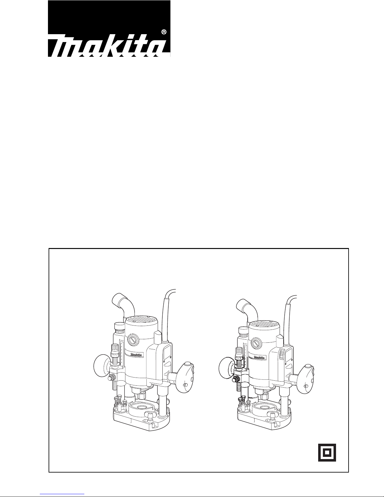
Adjusting the depth of cut (Fig.3)
Place the tool on a flat surface.
Loosen the lock knob and lower the tool body until the bit
just touches the flat surface. Tighten the lock knob to lock
the tool body.
Turn the stopper pole setting nut counterclockwise.
Lower the stopper pole until it makes contact with the
adjusting bolt. Align the depth pointer with the “0” graduation. The depth of cut is indicated on the scale by the
depth pointer.
While pressing the fast-feed button, raise the stopper
pole until the desired depth of cut is obtained. Minute
depth adjustments can be obtained by turning the adjusting knob (1 mm per turn.)
By turning the stopper pole setting nut clockwise, you
can fasten the stopper pole firmly.
Now, your predetermined depth of cut can be obtained by
loosening the lock knob and then lowering the tool body
until the stopper pole makes contact with the adjusting
bolt of the stopper block.
Nylon nut (Fig.4)
CAUTION:
• Do not lower the nylon nut too low or the bit will pro-
trude dangerously.
By turning the nylon nut, the upper limit of the tool body
can be adjusted. When the tip of the bit is retracted more
than required in relation to the base plate surface, turn
the nylon nut to lower the upper limit.
Page 8

8
CAUTION:
• Since excessive cutting may cause overload of the
motor or difficulty in controlling the tool, the depth of cut
should not be more than 15 mm at a pass when cutting
grooves with an 8 mm diameter bit.
• When cutting grooves with a 20 mm diameter bit, the
depth of cut should not be more than 5mm at a pass.
• For extra-deep grooving operations, make two or three
passes with progressively deeper bit settings.
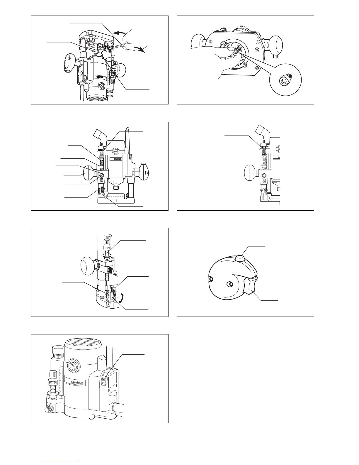
Stopper block (Fig. 5)
The stopper block has three adjusting hex bolts which
raise or lower 0.8 mm per turn. You can easily obtain
three different depths of cut using these adjusting hex
bolts without readjusting the stopper pole.
Adjust the lowest hex bolt to obtain the deepest depth of
cut. Adjust the two remaining hex bolts to obtain shallower depths of cut. The differences in height of these
hex bolts are equal to the differences in depths of cut. To
adjust the hex bolts, first loosen the hex nuts on the hex
bolts with the wrench and then turn the hex bolts. After
obtaining the desired position, tighten the hex nuts while
holding the hex bolts in that desired position. The stopper
block is also convenient for making three passes with
progressively deeper bit settings when cutting deep
grooves.
Switch action (Fig.6)
CAUTION:
• Before plugging in the tool, always check to see that
the switch trigger actuates properly and returns to the
“OFF” position when released.
• Make sure that the shaft lock is released before the
switch is turned on.
To start the tool, depress the lock button and pull the
switch trigger. Release the switch trigger to stop. For continuous operation, pull the trigger and then depress the
lock button further.
To stop the tool, pull the trigger so that the lock-off button
returns automatically. Then release the trigger. After
releasing the trigger, the lock-off function works to prevent the switch trigger from being pulled.
Speed adjusting dial (Fig.7)
For RP1110C
The tool speed can be infinitely adjusted between 8,000
and 24,000 min
-1
by turning the speed adjusting dial.
This allows the ideal speed to be selected for optimum
material processing, i.e. the speed can be correctly
adjusted to suit the material and bit diameter.
Refer to the table below for the relationship between the
number settings on the dial and the approximate rotating
speed.
CAUTION:
The speed adjusting dial can be turned only as far as 5
and back to 1. Do not force it past 5 or 1, or the speed
adjusting function may no longer work.
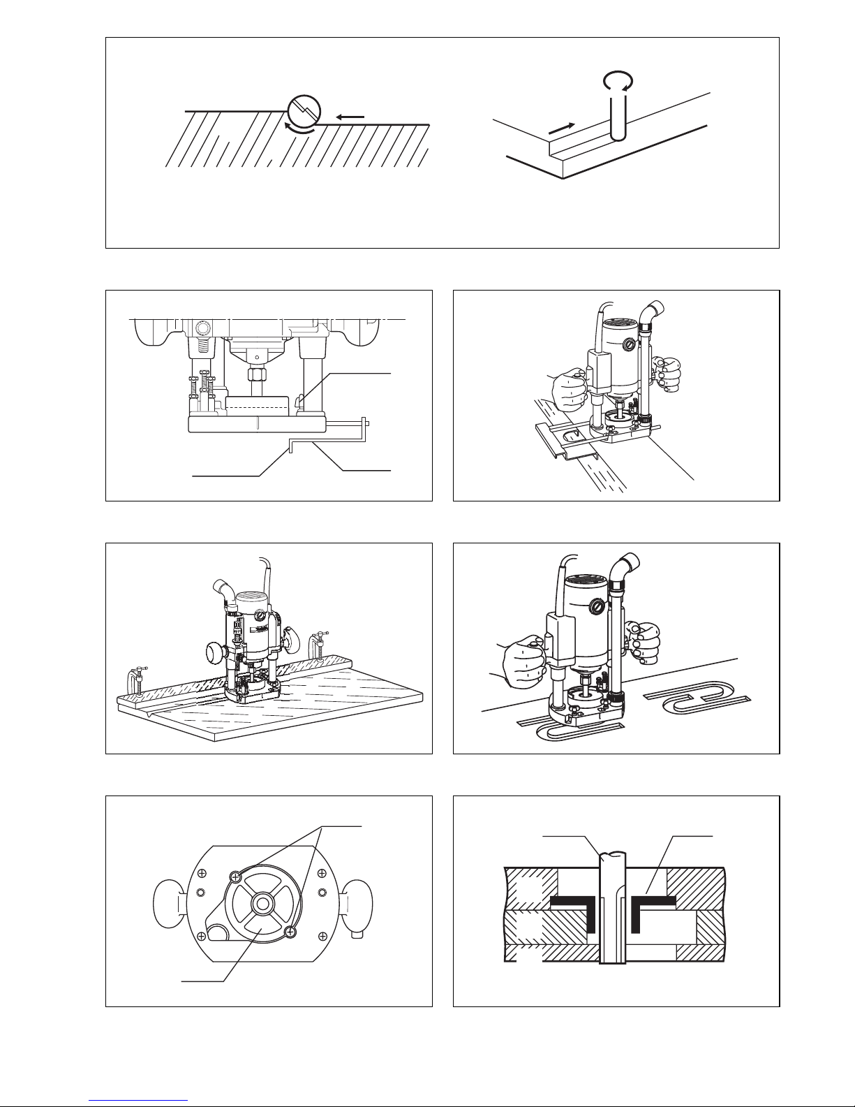
Operation (Fig. 8)
• Set the tool base on the workpiece to be cut without the
bit making any contact. Then turn the tool on and wait
until the bit attains full speed. Lower the tool body and
move the tool forward over the workpiece surface,
keeping the tool base flush and advancing smoothly
until the cutting is complete.
• When doing edge cutting, the workpiece surface
should be on the left side of the bit in the feed direction.
NOTE:
• Make sure that the tool raises automatically when the
lock knob is loosened. The position of the bit must be
higher than the tool base.
• Also, make sure that the dust guide is installed properly.
• Moving the tool forward too fast may cause a poor quality of cut, or damage to the bit or motor. Moving the tool
forward too slowly may burn and mar the cut. The
proper feed rate will depend on the bit size, the kind of
workpiece and depth of cut. Before beginning the cut
on the actual workpiece, it is advisable to make a sample cut on a piece of scrap lumber. This will show
exactly how the cut will look as well as enable you to
check dimensions.
• When using the straight guide, be sure to install it on
the right side in the feed direction. This will help to keep
it flush with the side of the workpiece.
Straight guide (Fig. 9, 10 & 11)
The straight guide is effectively used for straight cuts
when chamfering or grooving.
To install the straight guide, insert the guide bars into the
holes in the tool base. Adjust the distance between the
bit and the straight guide. At the desired distance, tighten
the lock screw to secure the straight guide in place.
When cutting, move the tool with the straight guide flush
with the side of the workpiece.
If the distance between the side of the workpiece and the
cutting position is too wide for the straight guide, the
straight guide cannot be used. In this case, firmly clamp
a straight board to the workpiece and use it as a guide
against the router base.
Templet guide (optional accessory)
(Fig. 12, 13 & 14)
The templet guide provides a sleeve through which the
bit passes, allowing use of the router with templet patterns.
To install the templet guide, insert the templet guide into
the tool base and then tighten the screws.
Secure the templet to the workpiece. Place the tool on
the templet and move the tool with the templet guide sliding along the side of the templet.
Number min
-1
18,000
2 12,000
3 16,000
4 20,000
5 24,000
Page 9

9
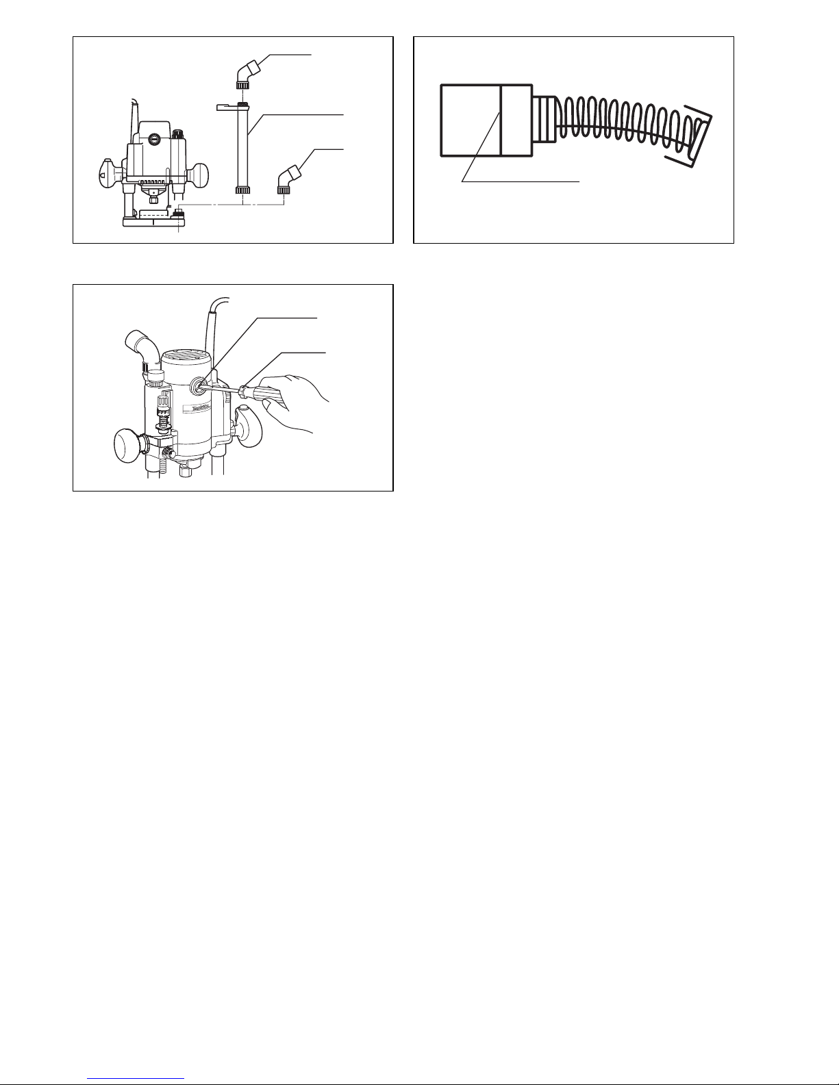
Connecting to Makita vacuum cleaner or dust
collector (Fig.15)
Cleaner operations can be performed by connecting the
router to Makita vacuum cleaner or dust collector.
Insert the nozzle assembly and the dust nozzle assembly
into the router. Also, the dust nozzle assembly can be
inserted into the router base directly in accordance with
the operation.
When connecting to Makita vacuum cleaner (Model 406/
431), an optional hose 28 mm in inner diameter is necessary.
When connecting to Makita dust collector (Model 420S),
the optional hose is not necessary . You can connect the
router directly to the hose of the dust collector.
MAINTENANCE
CAUTION:
Always be sure that the tool is switched off and
unplugged before carrying out any work on the tool.
Replacement of carbon brushes
(Fig. 16 & 17)
Replace carbon brushes when they are worn down to the
limit mark. Both identical carbon brushes should be
replaced at the same time.
To maintain product safety and reliability, repairs, maintenance or adjustment should be carried out by a Makita
Authorized Service Center.
Noise and Vibration of Model RP0910
ENG004-1
The typical A-weighted sound pressure level is 82 dB (A).
The noise level under working may exceed 85 dB (A).
– Wear ear protection. –
The typical weighted root mean square acceleration
value is 5 m/s
2
.
Noise and Vibration of Model RP1110C
ENG003-1
The typical A-weighted sound pressure level is 80 dB (A).
The noise level under working may exceed 85 dB (A).
– Wear ear protection. –
The typical weighted root mean square acceleration
value is not more than 2.5 m/s
2
.
EC-DECLARATION OF CONFORMITY
ENH001-1
We declare under our sole responsibility that this product
is in compliance with the following standards of standardized documents,
HD400, EN50144, EN55014, EN61000
in accordance with Council Directives, 73/23/EEC,
89/336/EEC and 98/37/EC.
Yasuhiko Kanzaki
CE 2003
Director
MAKITA INTERNATIONAL EUROPE LTD.
Michigan Drive, Tongwell, Milton Keynes,
Bucks MK15 8JD, ENGLAND
Page 10

10
DEUTSCH
Übersicht
1 Spannzangenmutter
2 Schraubenschlüssel
3 Spindelarretierung
4 Anziehen
5Lösen
6 Spannzangenkonus der
korrekten Größe
7 Anschlagstange
8 Tiefenzeiger
9 Feststellknopf
10 Schnellvorschubknopf
11 Sechskant-Einstellschraube
12 Einstellknopf
13 Anschlagblock
14 Nylonmutter
15 Sechskantmutter
16 Arretierknopf
17 Ein-Aus-Schalter
18 Drehzahl-Stellrad
19 Werkstück
20 Fräserdrehrichtung
21 Vorschubrichtung
22 (Ansicht von Werkzeug-
Oberseite)
23 Korrekte Fräservorschubrich-
tung
24 Feststellschraube
25 Führungskante
26 Parallelanschlag
27 Kopierhülse
28 Schraube
29 Fräser
30 Gleitschuh
31 Schablone
32 Werkstück
33 Kopierhülse
34 Absaugrohr
35 Absaugstutzen
36 Verschleißgrenze
37 Bürstenhalterkappe
38 Schraubendreher
39 Anschlagstangen-
Feststellmutter
TECHNISCHE DATEN
Modell RP0910 RP1110C
Max. Spannzangenkapazität ....................................................... ø8 mm ø8 mm
Hubhöhe ...................................................................................... 0– 57 mm 0 – 57 mm
Leerlaufdrehzahl (min
–1
) ............................................................. 27 000 8 000 – 24 000
Gesamthöhe ................................................................................ 260 mm 260 mm
Nettogewicht ................................................................................ 3,3 kg 3,4 kg
• Wir behalten uns vor, Änderungen im Zuge der Ent-
wicklung und des technischen Fortschritts ohne vorherige Ankündigung vorzunehmen.
• Hinweis: Die technischen Daten können von Land zu
Land abweichen.
Netzanschluß
Die Maschine darf nur an die auf dem Typenschild angegebene Netzspannung angeschlossen werden und
arbeitet nur mit Einphasen-Wechselspannung. Sie ist
entsprechend den Europäischen Richtlinien doppelt
schutzisoliert und kann daher auch an Steckdosen ohne
Erdanschluß betrieben werden.
SICHERHEITSHINWEISE
Achtung! Beim Gebrauch von Elektrowerkzeugen
sind zum Schutz gegen elektrischen Schlag. Verletzungsund Brandgefahr folgende grundsätzlichen Sicherheitsmaßnahmen zu geachten.
Lesen und beachten Sie diese Hinweise, bevor
Sie das Gerät benutzen.
1. Halten Sie Ihren Arbeitsbereich in Ordnung
Unordnung im Arbeitsbereich ergibt Unfallgefahr.
2. Berücksichtigen Sie Umgebungseinflüsse
Setzen sie Elektrowerkzeuge nicht dem Regen aus.
Benützen Sie Elektrowerkzeuge nicht in feuchter
oder nasser Umgebung. Sorgen Sie für gute
Beleuchtung. Benützen Sie Elektrowerkzeuge nicht
in Nähe von brennbaren Flüssigkeiten oder Gasen.
3. Schützen Sie sich vor elektrischem Schlag
Vermeiden Sie Körperberührung mit geerdeten Teilen, zum Beispiel Rohren, Heizkörpern, Herden,
kühlschränken.
4. Halten Sie Kinder fern!
Lassen Sie andere Personen nicht das Werkzeug
oder Kabel berühren, halten Sie sie von Ihrem
Arbeitsbereich fern.
5. Bewahren Sie Ihre Werkzeuge sicher auf
Unbenutzte Werkzeuge sollten in trockenem, verschlossenem Raum und für Kinder nicht erreichbar
aufbewahrt werden.
6. Überlasten Sie Ihr Werkzeug nicht
Sie arbeiten besser und sicherer im angegebenen
Leistungsbereich.
7. Benützen Sie das richtige Werkzeug
Verwenden Sie keine zu schwachen Werkzeuge
oder Vorsatzgeräte für schwere Arbeiten.
Benützen Sie Werkzeuge nicht für Zwecke und
Arbeiten, Wofür sie nicht bestimmt sind; zum Beispiel benützen Sie keine Handkreissäge, um Bäume
zu flällen oder Äste zu schneiden.
8. Tragen Sie geeignete Arbeitskleidung
Tragen Sie keine weite Kleidung oder Schmuck. Sie
können von beweglichen Teilen erfaßt werden. Bei
Arbeiten im Freien sind Gummihandschuhe und
rutschfestes Schuhwerk empfehlenswert. Tragen
Sie bei langen Haaren ein Haarnetz.
9. Schutzbrille und Gehörschutz tragen
Verwenden Sie eine Atemmaske bei stauberzeugenden Arbeiten.
10. Schlleßen Sie eine Staubabsaugvorrichtung an
Wenn Geräte für den Anschluß von Staubabsaugund-sammelvorrichtungen ausgelegt sind, sorgen
Sie dafür, daß Jiese angeschlossen und korrekt
benutzi werden.
11. Zweckentfremden Sie nicht das Kabel
Tragen Sie das Werkzeug nicht am Kabel, und
benützen Sie es nicht, um den Stecker aus der
Steckdose zu ziehen. Schützen Sie das Kabel vor
Hitze, Öl und scharfen Kanten.
Page 11

11
12. Sichern Sie das Werkstück
Benützen Sie Spannvorrichtungen oder einen
Schraubstock, um das Werkstück festzuhalten. Es
ist damit sicherer gehalten als mit Ihrer Hand und
ermöglicht die Bedienung der Maschine mit beiden
Händen.
13. Überdehnen Sie nicht Ihren Standbereich
Vermeiden Sie abnormale Körperhaltung. Sorgen
Sie für sicheren Stand, und halten Sie jederzeit das
Gleichgewicht.
14. Pflegen Sie Ihre Werkzeuge mit Sorgtalt
Halten Sie Ihre Werkzeuge scharf und sauber, um
gut und sicher zu arbeiten. Befolgen Sie die Wartungsvorschriften und die Hinweise für Werkzeugwechsel. Kontrollieren Sie regelmäßig den Stecker
und das Kabel, und lassen Sie diese bei Beschädigung von einem anerkannten Fachmann erneuern.
Kontrollieren Sie Verlängerungskabel regelmäßig
und ersetzen Sie beschädigte. Halten Sie Handgriffe
trocken und frei von Öl und Fett.
15. Ziehen Sie den Netzstecker
Bei Nichtgebrauch, vor der Wartung und beim Werkzeugwechsel, wie zum Beispiel Sägeblatt, Bohrer
und Maschinenwerkzeugen aller Art.
16. Lassen Sie keine Werkzeugschlüssel stecken
Überprüfen Sie vor dem Einschalten, daß die
Schlüssel und Einstellwerkzeuge entfernt sind.
17. Vermeiden Sie unbeabsichtigten Anlauf
Tragen Sie keine an das Stromnetz angeschlossene
Werkzeuge mit dem Finger am Schalter. Vergewissern Sie sich, daß der Schalter beim Anschluß an
das Stromnetz ausgeschaltet ist.
18. Verlängerungskabel im Freien
Verwenden Sie im Freien nur dafür zugelassene
und entsprechend gekennzeichnete Varlängerungskabel.
19. Seien Sie stets aufmerksam
Beobachten Sie Ihre Arbeit. Gehen Sie vernünftig
vor. Verwenden Sie das Werkzeug nicht, wenn Sie
unkonzentriert sind.
20. Kontrollieren Sie Ihr Gerät auf Beschädigungen
Vor weiterem Gebrauch des Werkzeugs die Schutzeinrichtungen oder leicht beschädigte Teile sorgfältig auf ihre einwandfreie und bestimmungsgemäße
Funktion überprüfen. Überprüfen Sie, ob die Funktion beweglicher Teile in Ordnung ist, ob sie nicht
klemmen onder ob Teile beschädigt sind. Sämtliche
Teile müssen richtig montiert sein und alle Bedingungen erfüllen, um den einwandfreien Betrieb des
Gerätes zu gewährleisten.
Beschädigte Schutzvorrichtungen und Teile sollen
sachgemäß durch eine Kundendienstwerkstatt repariert oder ausgewechselt werden, soweit nichts
anderes in den Betriebsanleitungen angegeben ist.
Beschädigte Schalter müssen bei einer Kundendienstwerkstatt ersetzt werden. Benutzen Sie keine
Werkzeuge, bei denen sich der Schalter nicht ein
und ausschalten läßt.
21. Achtung!
Zu Ihrer eigenen Sicherheit, benützen Sie nur Zubehör und Zusatzgeräte, die in der Bedienungsanleitung angegeben oder vom Werkzeug-Hersteller
empfohlen oder angegeben werden. Der Gebrauch
anderer als der in der Bedienungsanleitung oder im
Katalog empfohlenen Einsatzwerkzeuge oder Zubehöre kann eine persönliche Verletzungsgefahr für
Sie bedeuten.
22. Reparaturen nur vom Elektrofachmann.
Dieses Elektrowerkzeug entspricht den einschlägigen Sicherheitsbestimmungen. Reparaturen dürfen
nur von einer Elektrofachkraft ausgeführt werden,
andernfalls können Unfälle für den Betreiber entstehen.
ZUSÄTZLICHE
SICHERHEITSBESTIMMUNGEN
1. Halten Sie das Werkzeug nur an den isolierten
Griffflächen, wenn Sie Arbeiten ausführen, bei
denen die Gefahr besteht, dass verborgene
Kabel oder das eigene Kabel angebohrt werden.
Bei Kontakt mit einem stromführenden Kabel
werden die freiliegenden Metallteile des Werkzeugs ebenfalls stromführend, so dass der
Benutzer einen elektrischen Schlag erleiden
kann.
2. Tragen Sie einen Gehörschutz bei längerer
Betriebsdauer.
3. Behandeln Sie die Fräser mit größter Sorgfalt.
4. Überprüfen Sie den Fräser vor dem Betrieb sorgfältig auf Risse oder Beschädigung. Wechseln
Sie einen gerissenen oder beschädigten Fräser
unverzüglich aus.
5. Keine Nägel durchschneiden. Untersuchen Sie
das Werkstück sorgfältig auf Nägel, und entfernen Sie diese vor der Bearbeitung.
6. Halten Sie das Werkzeug mit beiden Händen
fest.
7. Halten Sie die Hände von rotierenden Teilen fern.
8. Vergewissern Sie sich vor dem Einschalten des
Werkzeugs, dass der Fräser nicht das Werkstück
berührt.
9. Lassen Sie das Werkzeug vor dem eigentlichen
Schneiden eines Werkstücks eine Weile laufen.
Achten Sie auf Vibrationen oder Taumelbewegungen, die Anzeichen für schlechte Montage
des Fräsers sein können.
10. Achten Sie auf die Drehrichtung und Vorschubrichtung des Fräsers.
11. Lassen Sie das Werkzeug nicht unbeaufsichtigt
laufen. Benutzen Sie das Werkzeug nur mit
Handhaltung.
12. Schalten Sie das Werkzeug stets aus und warten
Sie, bis der Fräser zum völligen Stillstand
kommt, bevor Sie das Werkzeug vom Werkstück
abnehmen.
13. Vermeiden Sie eine Berührung des Fräsers
unmittelbar nach der Bearbeitung, weil er dann
noch sehr heiß ist und Hautverbrennungen verursachen kann.
14. Führen Sie das Stromversorgungskabel stets
nach hinten vom Werkzeug weg.
BEWAHREN SIE DIESE HINWEISE
SORGFÄLTIG AUF.
Page 12

12
BEDIENUNGSHINWEISE
Montage und Demontage des Fräsers
Wichtig:
Vergewissern Sie sich vor der Montage oder Demontage
des Fräsers stets, dass das Werkzeug ausgeschaltet und
vom Stromnetz getrennt ist.
Die Spannzangenmutter lösen. Den Fräser bis zum
Anschlag in den Spannzangenkonus einführen. Die Spindelarretierung zum Blockieren der Spindel drücken, und
die Spannzangenmutter mit dem Schraubenschlüssel
fest anziehen. (Abb. 1)
Das Werkzeug wurde werksseitig mit einem 8-mm- oder
1/4"-Spannzangenkonus bestückt. Wenn Fräser mit
anderem Schaftdurchmesser verwendet werden sollen,
ist ein Spannzangenkonus der korrekten Größe für den
betreffenden Fräser zu verwenden. (Abb. 2)
Spannzangenkonusse der Größen 6 mm, 8 mm und 1/4"
sind gesondert erhältlich.
Zum Demontieren des Fräsers ist das Montageverfahren
umgekehrt anzuwenden.
VORSICHT:
Die Spannzangenmutter nicht anziehen, ohne einen Fräser einzusetzen, weil sonst der Spannzangenkonus
bricht.
Einstellen der Schnitttiefe (Abb. 3)
Das Werkzeug auf eine ebene Fläche stellen.
Den Feststellknopf lösen, und den Werkzeugkörper
absenken, bis der Fräser die Stellfläche leicht berührt.
Den Werkzeugkörper durch Anziehen des Feststellknopfes arretieren.
Drehen Sie die Anschlagstangen-Feststellmutter entgegen dem Uhrzeigersinn. Die Anschlagstange absenken,
bis sie mit der Einstellschraube in Berührung kommt.
Den Tiefenzeiger auf den Skalenstrich “0” ausrichten.
Die Schnitttiefe wird durch den Tiefenzeiger auf der
Skala angezeigt.
Die Anschlagstange bei gedrücktem Schnellvorschubknopf anheben, bis die gewünschte Schnitttiefe erreicht
ist. Eine Feineinstellung kann durch Drehen des Einstellknopfes vorgenommen werden (1 mm pro Umdrehung).
Durch Drehen der Anschlagstangen-Feststellmutter im
Uhrzeigersinn kann die Anschlagstange sicher arretiert
werden.
Nun kann die voreingestellte Schnitttiefe erreicht werden,
indem der Feststellknopf gelöst und der Werkzeugkörper
abgesenkt wird, bis die Anschlagstange mit der Einstellschraube des Anschlagblocks in Berührung kommt.
Nylonmutter (Abb. 4)
VORSICHT:
• Senken Sie die Nylonmutter nicht zu weit ab, weil sonst
der Fräser gefährlich weit übersteht.
Durch Drehen der Nylonmutter kann die Obergrenze des
Werkzeugkörpers eingestellt werden. Wenn die Spitze
des Fräsers in Bezug auf die Führungsschuhfläche weiter eingezogen wird als erforderlich, kann die Obergrenze durch Drehen der Nylonmutter abgesenkt
werden.
VORSICHT:
• Da eine übermäßige Schnitttiefe eine Überlastung des
Motors oder schlechte Kontrolle des Werkzeugs verursachen kann, sollte die Schnitttiefe nicht mehr als 15
mm pro Durchgang betragen, wenn Nuten mit einem 8mm-Fräser gefräst werden.
• Wenn Nuten mit einem 20-mm-Fräser gefräst werden,
sollte die Schnitttiefe nicht mehr als 5 mm pro Durchgang betragen.
• Um besonders tiefe Nuten zu fräsen, sind zwei oder
drei Durchgänge mit zunehmender Schnitttiefe durchzuführen.
Anschlagblock (Abb. 5)
Der Anschlagblock besitzt drei Sechskant-Einstellschrauben, die den Block um 0,8 mm pro Umdrehung anheben
bzw. absenken. Mit diesen Sechskant-Einstellschrauben
können drei verschiedene Schnitttiefen bequem eingestellt werden, ohne die Anschlagstange zu verstellen.
Die unterste Sechskantschraube zur Einstellung der
größten Schnitttiefe verwenden. Die übrigen zwei Sechskantschrauben zur Einstellung geringerer Schnitttiefen
verwenden. Die Höhenunterschiede dieser Sechskantschrauben entsprechen den unterschiedlichen Schnitttiefen. Zum Einstellen der Sechskantschrauben zuerst die
Sechskantmuttern der Schrauben mit dem Schraubenschlüssel lösen, und dann die Sechskantschrauben drehen. Nach Erreichen der gewünschten Position die
Sechskantmuttern anziehen, während die Sechskantschrauben in dieser Position gehalten werden. Der
Anschlagblock ist auch praktisch, um tiefe Nuten in drei
Durchgängen mit zunehmend größerer Schnitttiefen-Einstellung zu fräsen.
Schalterbedienung (Abb. 6)
VORSICHT:
• Vergewissern Sie sich vor dem Anschließen des Werkzeugs an das Stromnetz stets, dass der Ein-Aus-Schalter ordnungsgemäß funktioniert und beim Loslassen in
die AUS-Stellung zurückkehrt.
• Vergewissern Sie sich vor dem Einschalten des Werkzeugs, dass die Spindelarretierung freigegeben ist.
Zum Starten des Werkzeugs den Ein-Aus-Schalter bei
gedrücktem Arretierknopf betätigen. Zum Anhalten den
Ein-Aus-Schalter loslassen. Für Dauerbetrieb den EinAus-Schalter betätigen, und dann den Arretierknopf weiter hineindrücken.
Zum Anhalten des Werkzeugs den Ein-Aus-Schalter
betätigen, so dass der Arretierknopf automatisch herausspringt. Dann den Ein-Aus-Schalter loslassen. Nach dem
Loslassen des Ein-Aus-Schalters verhindert die Einschaltsperre eine ungewollte Betätigung des Ein-AusSchalters.
Page 13

13
Drehzahl-Stellrad (Abb. 7)
Für RP1110C
Die Drehzahl des Werkzeugs kann durch Drehen des
Drehzahl-Stellrads zwischen 8 000 und 24 000 min–1 stufenlos eingestellt werden. Dies gestattet die Wahl der
idealen Drehzahl für eine optimale Materialbearbeitung,
d.h. die Drehzahl kann auf einen für Material und Fräserdurchmesser optimalen Wert eingestellt werden.
Die ungefähren Drehzahlen für die einzelnen StellradPositionen sind aus der nachstehenden Tabelle ersichtlich.
VORSICHT:
Das Drehzahl-Stellrad lässt sich nur bis 5 und zurück auf
1 drehen. Wird es gewaltsam über 5 oder 1 hinaus
gedreht, lässt sich die Drehzahl möglicherweise nicht
mehr einstellen.
Betrieb (Abb. 8)
• Den Gleitschuh auf das zu schneidende Werkstück
aufsetzen, ohne dass der Fräser irgendwelchen Kontakt hat. Dann das Werkzeug einschalten und warten,
bis der Fräser die volle Drehzahl erreicht. Den Werkzeugkörper absenken und das Werkzeug gleichmäßig
und mit flach aufliegendem Gleitschuh über die Werkstück-Oberfläche vorschieben, bis der Schnitt vollendet
ist.
• Beim Kantenfräsen sollte sich die Werkstück-Oberfläche links vom Fräser in Vorschubrichtung befinden.
HINWEIS:
• Vergewissern Sie sich, dass sich das Werkzeug automatisch hebt, wenn der Feststellknopf gelöst wird. Der
Fräser muss höher als der Gleitschuh liegen.
• Achten Sie auch darauf, dass der Absaugstutzen korrekt installiert ist.
• Eine zu hohe Vorschubgeschwindigkeit des Werkzeugs
kann schlechte Schnittqualität oder Beschädigung von
Fräser oder Motor zur Folge haben. Eine zu geringe
Vorschubgeschwindigkeit kann Verbrennung und Verunstaltung des Schnitts zur Folge haben. Die korrekte
Vorschubgeschwindigkeit hängt von der Fräsergröße,
der Art des Werkstücks und der Schnitttiefe ab. Bevor
Sie den Schnitt am eigentlichen Werkstück ausführen,
ist es ratsam, einen Probeschnitt an einem Stück
Abfallholz durchzuführen. Dadurch erhalten Sie eine
genaue Vorstellung vom Aussehen des Schnitts, und
Sie haben die Möglichkeit, die Maße zu prüfen.
• Wenn Sie den Parallelanschlag verwenden, montieren
Sie ihn auf der rechten Seite in Vorschubrichtung.
Dadurch ist gewährleistet, dass er bündig an der Werkstückkante anliegt.
Parallelanschlag (Abb. 9, 10 und 11)
Der Parallelanschlag ist praktisch zur Ausführung gerader Schnitte beim Anfasen oder Auskehlen.
Zum Montieren des Parallelanschlags die Führungsstangen in die Löcher im Gleitschuh einführen. Den Abstand
zwischen Fräser und Parallelanschlag einstellen. Beim
gewünschten Abstand die Feststellschraube anziehen,
um den Parallelanschlag zu arretieren.
Führen Sie das Werkzeug beim Fräsen so, dass der Parallelanschlag bündig an der Werkstückkante anliegt.
Falls der Abstand zwischen der Werkstückkante und der
Schneidposition zu groß für den Parallelanschlag ist,
kann der Parallelanschlag nicht benutzt werden. In diesem Fall kann ein gerades Brett gegen das Werkstück
geklemmt und als Führung für den Gleitschuh verwendet
werden.
Kopierhülse (Sonderzubehör)
(Abb. 12, 13 und 14)
Die Kopierhülse besitzt eine Öffnung, durch die der Fräser abgesenkt wird, so dass die Oberfräse mit Schablonen verwendet werden kann.
Die Kopierhülse zum Montieren in den Gleitschuh einführen, und dann die Schrauben anziehen.
Die Schablone am Werkstück befestigen. Das Werkzeug
auf die Schablone setzen und so führen, dass die Kopierhülse an der Kante der Schablone entlanggleitet.
Anschluss eines Makita-Staubsaugers oder
Absauggerätes (Abb. 15)
Der Anschluss eines Makita-Staubsaugers oder Absauggerätes an der Oberfräse gestattet saubereres Arbeiten.
Das Absaugrohr und den Absaugstutzen an der Oberfräse anbringen. Je nach Art der Arbeit kann der
Absaugstutzen auch direkt am Gleitschuh der Oberfräse
angeschlossen werden.
Zum Anschluss an einen Makita-Staubsauger (Modell
406/431) wird ein gesonderter Schlauch von 28 mm
Innendurchmesser benötigt.
Zum Anschluss an ein Makita-Absauggerät (Modell
420S) wird der gesonderte Schlauch nicht benötigt. Die
Oberfräse kann direkt an den Schlauch des Absauggerätes angeschlossen werden.
WARTUNG
VORSICHT:
Vor Arbeiten an der Maschine vergewissern Sie sich, daß
sich der Schalter in der “AUS-” Position befindet und der
Netzstecker gezogen ist.
Kohlebürsten wechseln (Abb.16 u. 17)
Kohlebürsten ersetzen, wenn sie bis auf die Verschleißgrenze abgenutzt sind. Beide Kohlebürsten nur paarweise ersetzen.
Um die Sicherheit und Zuverlässigkeit dieses Gerätes zu
gewährleisten, sollten Reparatur-, Wartungs-, und Einstellarbeiten nur von Makita autorisierten Werkstätten
oder Kundendienstzentren unter ausschließlicher Verwendung von Makita-Originalersatzteilen ausgeführt
werden.
Position min
-1
18000
212000
316000
420000
524000
Page 14

14
Geräusch- und Vibrationsentwicklung des
Modells RP0910
ENG004-1
Der typische A-bewertete Schalldruckpegel beträgt
82 dB (A).
Der Lärmpegel kann während des Betriebs 85 dB (A)
überschreiten.
– Gehörschutz tragen. –
Der gewichtete Effektivwert der Beschleunigung beträgt
5 m/s2.
Geräusch- und Vibrationsentwicklung des
Modells RP1110C
Der typische A-bewertete Schalldruckpegel beträgt
80 dB (A).
Der Lärmpegel kann während des Betriebs 85 dB (A)
überschreiten.
– Gehörschutz tragen. –
Der gewichtete Effektivwert der Beschleunigung beträgt
nicht mehr als 2.5 m/s
2
.
CE-KONFORMITÄTSERKLÄRUNG
ENH001-1
Hiermit erklärt wir unter unserer alleinigen Verantwortung, daß dieses Produkt gemäß den Ratsdirektiven 73/
23/EWG, 89/336/EWG und 98/37/EG mit den folgenden
Normen von Normendokumenten übereinstimmen:
HD400, EN50144, EN55014, EN61000.
Yasuhiko Kanzaki
CE 2003
Direktor
MAKITA INTERNATIONAL EUROPE LTD.
Michigan Drive, Tongwell, Milton Keynes,
Bucks MK15 8JD, ENGLAND
Page 15

1515
POLSKI
Wyjaśnienia dotyczące urządzenia i jego użycia
1 Nakrętka zaciskowa
2Klucz
3 Blokada wałka
4 Zakręcanie
5 Odkręcanie
6 Stożek zaciskowy o właściwym
rozmiarze
7 Wierzchołek stopera
8 Wskaźnik głębokości
9 Pokrętło blokady
10 Przycisk szybkiego przesuwu
11 Sześciokątna śruba regulacyjna
12 Pokrętło regulacyjne
13 Klocek stopera
14 Nakrętka plastikowa
15 Nakrętka sześciokątna
16 Przycisk pracy ciągłej
17 Spust włącznika
18 Pokrętło regulacji prędkości
19 Obrabiany przedmiot
20 Kierunek obrotów noża
21 Kierunek przesuwu
22 (Widok od góry urządzenia)
23 Właściwy kierunek przesuwu
noża
24 Śruba blokująca
25 Powierzchnia prowadząca
26 Prowadnica prosta
27 Prowadnica do wykrojów
28 Śruba
29 Nóż
30 Podstawa
31 Wykrój
32 Obrabiany przedmiot
33 Prowadnica do wykrojów
34 Zespół dyszy
35 Zespół dyszy pyłu
36 Znak limitu
37 Pokrywa pojemnika na
szczoteczkę
38 Śrubokręt
39 Nakrętka ustawiająca
wierzchołek stopera
DANE TECHNICZNE
Model RP0910 RP1110C
Maksymalne rozwarcie zacisku............................................ ø8 mm ø8 mm
Zakres cięcia wgłębnego ..................................................... 0 – 57mm 0 – 57 mm
Prędkość bez obciążenia (min–1) ......................................... 27000 8000 – 24000
Całkowita wysokość ............................................................ 260 mm 260 mm
Ciężar netto ......................................................................... 3,3 kg 3,4 kg
• Ze względu na prowadzony program udoskonaleń i
badań, podane dane techniczne mogą zostać
zmienione bez uprzedzenia.
• Uwaga: Dane techniczne mogą się różnić w zależności
od kraju.
Zasilanie
Urządzenie to, powinno być podłączone tylko do źródła
zasilania o takim samym napięciu jak pokazano na
tabliczce znamionowej i może być używane tylko dla
zmiennego prądu jednofazowego. Zgodnie ze
standardami Unii Europejskiej zastosowano podwójną
izolację i dlatego też możliwe jest zasilanie z gniazda bez
uziemienia.
INSTRUKCJE BEZPIECZEŃSTWA
Ostrzeżenie! Używając urządzeń elektrycznych
podstawowe środki ostrożności muszą być zawsze
zachowane, aby zmniejszyć ryzyko ognia, porażenia
prądem i uszkodzenia ciała, włączając poniższe.
Przeczytaj wszystkie podane instrukcje przed próbą
użycia tego produktu i zachowaj je do wglądu.
Dla bezpiecznego użycia:
1. Utrzymuj miejsce pracy w czystości
Zabałaganione miejsca i stoły warsztatowe
sprzyjają wypadkom.
2. Zastanów się nad warunkami pracy
Nie wystawiaj urządzeń elektrycznych na deszcz.
Nie używaj urządzeń elektrycznych w wilgotnych
lub mokrych miejscach. Utrzymuj miejsce pracy
dobrze oświetlone. Nie używaj urządzeń
elektrycznych w obecności łatwopalnych płynów
lub gazów.
3. Chroń się przed porażeniem prądem
Zapobiegaj kontaktom ciała z uziemionymi
powierzchniami (np. rurami, grzejnikami,
kuchenkami, lodówkami).
4. Nie pozwalaj zbliżać się dzieciom
Nie pozwalaj wizytującym osobom dotykać
urządzenia lub przedłużacza. Wszystkie wizytujące
osoby nie powinny zbliżać się do miejsca pracy.
5. Zachowaj nieczynne urządzenia
Nieużywane urządzenia powinny być
przechowywane w suchych, wysokich lub
zamykanych miejscach tak, aby były niedostępne
dla dzieci.
6. Nie przeciążaj urządzenia
Wykona ono pracę lepiej i bezpieczniej, pracując w
sposób, dla którego zostało ono zaprojektowane.
7. Używaj poprawnego urządzenia
Nie nadużywaj małych lub dodatkowych urządzeń
do wykonania pracy urządzeń do dużej pracy. Nie
używaj urządzeń do celów, do których nie zostały
przeznaczone; na przykład, nie używaj piły
tarczowej do przecinania gałęzi lub kłód drzew.
8. Ubierz się odpowiednio
Nie noś luźnych ubrań lub biżuterii. Mogą one
zostać zahaczone o ruchome części. Gumowe
rękawiczki i przeciwpoślizgowe buty są wskazane
przy pracy na dworze. Zaleca się noszenie ochrony
na głowę przytrzymującej długie włosy.
9. Użyj okularów ochronnych i ochraniaczy uszu
Użyj masek na twarz lub masek przeciwpyłowych
jeżeli czynność cięcia wytwarza pyły.
10. Podłącz urządzenie usuwające pył
Jeżeli urządzenia posiadają podłączenia do
urządzeń do usuwania i składowania pyłu, upewnij
się, że są one poprawnie podłączone i użyte.
11. Uważaj na przewód sieciowy
Nigdy nie noś urządzenia trzymając za przewód i
nie odłączaj go od gniazda przez pociągnięcie
przewodu. Chroń przewód przed ciepłem, olejem i
ostrymi krawędziami.
Page 16

1616
12. Pewnie mocuj obrabiane elementy
Użyj ścisków lub imadła do zamocowania
obrabianych elementów. Jest to bezpieczniejsze niż
używanie rąk, a dodatkowo zwalnia obie ręce do
obsługiwania urządzenia.
13. Używając urządzenie, nie oddalaj go zbytnio od
siebie
Cały czas trzymaj dobrze ustawione nogi i
równowagę.
14. Pamiętaj o dobrej konserwacji urządzenia
Utrzymuj urządzenie ostre i czyste dla jego lepszego
i bezpieczniejszego działania. Wykonaj podane
instrukcje w celu smarowania lub wymiany
elementów wyposażenia. Regularnie sprawdzaj
przewody urządzenia, i jeżeli są uszkodzone, oddaj
je do naprawy do autoryzowanego serwisu.
Regularnie sprawdzaj przewody przedłużające i
wymień je, jeżeli są uszkodzone. Utrzymuj uchwyty
suche, czyste i nie zabrudzone olejem lub smarem.
15. Odłącz urządzenia
Przed konserwacją urządzenia lub zmianą
wyposażenia takiego jak tarcze, końcówki robocze i
noże, gdy nie jest ono używane.
16. Wyjmij klucze regulacyjne
Nabierz zwyczaju sprawdzania czy klucze
regulacyjne są usunięte z urządzenia przed jego
użyciem.
17. Unikaj przypadkowych uruchomień
Nie noś podłączonego urządzenia z palcem na
włączniku. Upewnij się, że urządzenie jest
wyłączone, gdy je podłączasz do zasilania.
18. Zastosuj przedłużacz używając urządzenia na
dworze
Gdy urządzenie używane jest na dworze, stosuj
tylko przedłużacze przeznaczone i oznaczone do
pracy na dworze.
19. Bądź uważny
Patrz co robisz. Bądź rozsądny. Nie używaj
urządzenia, gdy jesteś zmęczony.
20. Sprawdzaj uszkodzone części
Przed dalszym użyciem urządzenia, osłona lub inne
części, które są uszkodzone, muszą być uważnie
sprawdzone, aby upewnić się, że będą poprawnie
działać i wykonywać przeznaczone im funkcje.
Sprawdzaj ustawienia ruchomych części, oprawy
ruchomych części, pęknięcia części, zamocowania,
i jakiekolwiek inne warunki, które mogą wpływać na
działanie. Osłona lub inne części, które są
uszkodzone, powinny być naprawione lub
wymienione przez autoryzowany serwis, jeżeli w
instrukcji nie podano inaczej. Uszkodzone
przełączniki powinny być wymienione przez
autoryzowany serwis. Nie używaj urządzenia, jeżeli
włącznik nie może go włączyć lub wyłączyć.
21. Ostrzeżenie
Użycie jakiegokolwiek innego wyposażenia lub
części dodatkowych innych niż zalecane w tej
instrukcji obsługi lub katalogu, może stworzyć
ryzyko uszkodzenia ciała.
22. Naprawy urządzenia powinny być wykonywane
tylko przez specjalistę
To urządzenie jest wykonane zgodnie z
odpowiednimi zasadami bezpieczeństwa. Naprawa
urządzeń elektrycznych może być wykonana
wyłącznie przez specjalistę, gdyż w przeciwnym
wypadku może ono stanowić zagrożenie dla
użytkownika.
DODATKOWE ZALECENIA DOTYCZĄCE
BEZPIECZEŃSTWA
1. Podczas wykonywania prac, w trakcie których
urządzenie tnące może wejść w kontakt z
ukrytymi przewodami elektrycznymi lub
własnym przewodem zasilania, trzymaj je za
izolowane powierzchnie uchwytu. Kontakt z
przewodem elektrycznym pod napięciem może
sprawić, że odsłonięte, metalowe części
urządzenia znajdą się również pod napięciem, i
doprowadzić do porażenia operatora.
2. Podczas długiego używania zakładaj
ochraniacze na uszy.
3. Obchodź się z końcówkami roboczymi bardzo
ostrożnie.
4. Przed przystąpieniem do pracy dokładnie
sprawdź, czy końcówka nie jest popękana lub
uszkodzona. Wymień natychmiast popękaną lub
uszkodzoną końcówkę roboczą.
5. Unikaj przecinania gwoździ. Przed
przystąpieniem do pracy sprawdź obrabiany
przedmiot i usuń wszystkie gwoździe.
6. Trzymaj urządzenie pewnie.
7. Trzymaj ręce z daleka od obracających się
części.
8. Upewnij się, czy końcówka robocza nie dotyka
obrabianego przedmiotu przed włączeniem
urządzenia.
9. Przed użyciem urządzenia na obrabianym
przedmiocie uruchom je na chwilę bez
obciążenia. Zwróć uwagę na drgania lub bicie
osiowe, które mogą wskazywać na niewłaściwe
zamocowanie końcówki roboczej.
10. Zwróć uwagę na zgodność kierunku obrotów
końcówki roboczej i kierunku wycinania.
11.Nie pozostawiaj pracującego urządzenia.
Obsługuj urządzenie tylko wtedy, gdy trzymasz
je w ręce.
12. Przed wyjęciem końcówki roboczej z
obrabianego przedmiotu zawsze wyłącz
urządzenie i zaczekaj aż końcówka robocza
zatrzyma się całkowicie.
13. Zawsze układaj przewód zasilania z dala od
urządzenia, do tyłu.
14. Nie dotykaj końcówki roboczej natychmiast po
wycinaniu; może ona być bardzo gorąca i
poparzyć skórę.
ZACHOWAJ TĘ INSTRUKCJĘ.
Page 17

1717
INSTRUKCJA OBSŁUGI
Zakładanie lub zdejmowanie noża frezarskiego
Ważne:
Przed zakładaniem lub wyjmowaniem noża zawsze
upewnij się, czy urządzenie jest wyłączone i odłączone
od zasilania.
Odkręć nakrętkę zaciskową. Włóż nóż do końca do
stożka zacisku. Naciśnij blokadę wałka, aby
unieruchomić wałek, i zakręć mocno nakrętkę
zaciskową kluczem.
(Rys. 1)
Stożek zaciskowy 8 mm lub 1/4" jest założony
fabrycznie na urządzenie. Podczas używania noży
frezarskich o innej średnicy trzonu, używaj stożka
zaciskowego o rozmiarze właściwym dla używanego
noża.
(Rys. 2)
Wyposażenie dodatkowe zawiera stożki zaciskowe
6 mm, 8 mm i 1/4".
Aby wyjąć nóż, wykonaj czynności zakładania w
odwrotnej kolejności.
OSTRZEŻENIE:
Nie zakręcaj stożka zaciskowego bez włożonego noża,
bo możesz go złamać.
Regulacja głębokości frezowania (Rys. 3)
Ustaw urządzenie na płaskiej powierzchni.
Odkręć pokrętło blokady i obniż korpus urządzenia, aż
nóż zetknie się z płaską powierzchnią. Zakręć pokrętło
blokady, aby unieruchomić korpus urządzenia.
Obróć nakrętkę ustawiania wierzchołka stopera
przeciwnie do ruchu wskazówek zegara. Obniż
wierzchołek stopera, aż zetknie się on ze śrubą
regulacyjną. Ustaw wskaźnik głębokości naprzeciwko
„0” na skali. Głębokość frezowania będzie wskazywana
na podziałce przez wskaźnik głębokości.
Naciskając przycisk szybkiego przesuwu, podnieś
wierzchołek stopera, aż osiągnięta zostanie żądana
głębokość frezowania. Drobne regulacje głębokości
można uzyskać obracając pierścień regulacyjny (1 mm
na obrót).
Obracając nakrętkę ustawiania wierzchołka stopera
zgodnie z ruchem wskazówek zegara, można
zablokować pewnie wierzchołek stopera.
Można teraz uzyskać ustawioną głębokość frezowania,
odkręcając pokrętło blokady i obniżając korpus
urządzenia, aż wierzchołek stopera zetknie się ze śrubą
regulacyjną klocka stopera.
Nakrętka plastikowa (Rys. 4)
OSTRZEŻENIE:
• Nie obniżaj nadmiernie plastikowej nakrętki, bo nóż
może niebezpiecznie wystawać.
Obracając nakrętkę plastikową można ustawić górną
granicę korpusu urządzenia. Jeżeli wierzchołek noża
schowa się nadmiernie w stosunku do powierzchni płyty
podstawy, obróć nakrętkę plastikową, aby obniżyć
górną granicę korpusu.
OSTRZEŻENIE:
• Ponieważ nadmierne frezowanie może spowodować
przeciążenie silnika lub problemy z panowaniem nad
urządzeniem, głębokość frezowania przy używaniu
noży o średnicy 8 mm nie powinna być większa niż
15 mm na jedno przejście.
• Przy używaniu noży o średnicy 20 mm głębokość
frezowania nie powinna być większa niż 5 mm na
jedno przejście.
• W celu bardzo głębokiego frezowania wykonaj dwa lub
więcej przejść, ustawiając stopniowo większą
głębokość.
Klocek stopera (Rys. 5)
Klocek stopera posiada trzy sześciokątne śruby
regulacyjne, które podnoszą go lub opuszczają o
0,8 mm na obrót. Przy użyciu tych śrub można łatwo
uzyskać trzy różne głębokości frezowania bez
konieczności zmiany ustawiania wierzchołka stopera.
Wyreguluj najniższą ze śrub sześciokątnych, aby
uzyskać największą głębokość frezowania. Wyreguluj
dwie pozostałe śruby sześciokątne, aby uzyskać
mniejsze głębokości frezowania. Różnice wysokości
śrub są równe różnicom głębokości frezowania. Aby
ustawić śruby sześciokątne, najpierw odkręć kluczem
nakrętki sześciokątne na śrubach, a następnie obracaj
śruby. Po osiągnięciu żądanego położenia zakręć
nakrętki, przytrzymując śruby w żądanym położeniu.
Klocek stopera ułatwia też wykonanie trzech przejść ze
stopniowo wzrastającą głębokością podczas głębokiego
frezowania.
Działanie włącznika (Rys. 6)
OSTRZEŻENIE:
• Przed podłączeniem urządzenia do zasilania zawsze
sprawdź, czy spust włącznika działa poprawnie i
powraca do położenia „OFF” po zwolnieniu.
• Przed naciśnięciem włącznika upewnij się, czy
blokada wałka jest zwolniona.
Aby uruchomić urządzenie, naciśnij przycisk pracy
ciągłej i pociągnij za spust włącznika. Aby zatrzymać
urządzenie, zwolnij spust włącznika. W celu uzyskania
pracy ciągłej pociągnij za spust, a następnie naciśnij
dalej przycisk pracy ciągłej.
Aby zatrzymać urządzenie pociągnij za spust, aby
przycisk blokady wyskoczył automatycznie. Następnie
zwolnij spust. Po zwolnieniu spustu funkcja blokady
zacznie pracować, aby zapobiec pociągnięciu za spust.
Pokrętło regulacji prędkości (Rys. 7)
Model RP1110C
Prędkość urządzenia można dowolnie regulować
pomiędzy 8000 a 24000min-1, obracając pokrętło
regulacji prędkości. Pozwala to na wybór optymalnej
prędkości dla obrabianego materiału, tzn. można
ustawić prędkość w zależności od materiału i średnicy
noża.
Zależność pomiędzy liczbą ustawioną na pokrętle a
przybliżoną prędkością obrotów podana jest w poniższej
tabeli.
Liczba min
-1
1 8000
2 12000
3 16000
4 20000
5 24000
Page 18

1818
OSTRZEŻENIE:
Pokrętło regulacji prędkości można obracać tylko do 5 i
z powrotem do 1. Nie obracaj go na siłę poza 5 i 1, bo
funkcja regulacji prędkości może przestać działać.
Postępowanie (Rys. 8)
• Ustaw podstawę urządzenia na obrabianym
przedmiocie tak, aby nóż nie stykał się z nią.
Następnie włącz urządzenie i zaczekaj, aż nóż osiągnie
pełną prędkość. Obniż korpus urządzenia i przesuwaj
je do przodu po powierzchni obrabianego przedmiotu,
utrzymując podstawę płasko i przesuwając płynnie, aż
do zakończenia frezowania.
• Podczas frezowania brzegów powierzchnia
obrabianego przedmiotu powinna znajdować się po
lewej stronie noża w stosunku do kierunku przesuwu.
UWAGA:
• Upewnij się, czy urządzenie podnosi się
automatycznie po odkręceniu pokrętła blokady. Nóż
musi znajdować się powyżej podstawy urządzenia.
• Upewnij się także, czy rynna pyłu jest prawidłowo
założona.
• Zbyt szybkie przesuwanie urządzenia do przodu może
spowodować złą jakość frezowania lub uszkodzić nóż
lub silnik. Zbyt wolne przesuwanie urządzenia do
przodu może spowodować spalenie i zeszpecenie
frezu. Właściwa prędkość przesuwu zależy od
rozmiaru noża, rodzaju materiału i głębokości
frezowania. Przed zamierzonym frezowaniem zalecane
jest wykonanie próby na materiale odpadowym.
Pokaże to dokładnie, jak wyglądał będzie frez, i
pozwoli sprawdzić jego wymiary.
• Podczas używania prowadnicy prostej koniecznie
załóż ją po prawej stronie względem kierunku
przesuwu. Pomoże to utrzymać prowadnicę płasko z
brzegiem obrabianego przedmiotu.
Prowadnica prosta (Rys. 9, 10 i 11)
Prowadnica prosta jest używana skutecznie przy
frezowaniu prostym podczas żłobienia lub wycinania
bruzd.
Aby założyć prowadnicę prostą, włóż pręty prowadnicy
do otworów w podstawie urządzenia. Wyreguluj
odległość pomiędzy nożem a prowadnicą. Po
ustawieniu żądanej odległości zakręć śrubę blokady, aby
zamocować prowadnicę.
Podczas frezowania przesuwaj urządzenie z prowadnicą
poruszającą się płasko wzdłuż brzegu obrabianego
przedmiotu.
Jeżeli odległość pomiędzy brzegiem obrabianego
przedmiotu a miejscem frezowanie będzie zbyt duża dla
wykonania frezowania prostego, nie można używać
prowadnicy prostej. W takim przypadku najpierw
przymocuj zaciskami prostą płytę do obrabianego
przedmiotu i użyj jej jako prowadnicy dla podstawy
urządzenia.
Prowadnica do wykrojów (wyposażenie
dodatkowe) (Rys. 12, 13 i 14)
Prowadnica do wykrojów posiada tuleję, przez którą
przechodzi nóż, pozwalającą na używanie frezarki z
różnymi wykrojami.
Aby złożyć prowadnicę do wykrojów, nałóż ją na
podstawę urządzenia, a następnie zakręć śruby.
Przymocuj wykrój do obrabianego przedmiotu. Ustaw
urządzenie na wykroju i przesuwaj je z prowadnicą do
przekrojów poruszająca się wzdłuż boku wykroju.
Podłączanie do odkurzacza lub pochłaniacza
pyłu Makita (Rys. 15)
Podłączywszy frezarkę do odkurzacza lub pochłaniacza
pyłu Makita, można wykonywać czystszą pracę.
Nałóż zespół dyszy i zespół dyszy pyłu na frezarkę.
Zespół dyszy pyłu może być również założony na
podstawę frezarki w zależności od wykonywanej pracy.
W przypadku podłączania do odkurzacza Makita (model
406/431), potrzebny jest dodatkowy wąż o średnicy
wewnętrznej 28 mm.
W przypadku podłączania do pochłaniacza pyłu Makita
(model 420S), dodatkowy wąż nie jest potrzebny.
Frezarkę można podłączyć bezpośrednio do węża
pochłaniacza pyłu.
KONSERWACJA
OSTRZEŻENIE:
Zawsze upewnij się, że urządzenie jest wyłączone i
odłączone od zasilania przed wykonywaniem
jakichkolwiek prac nad urządzeniem.
Wymiana szczoteczek węglowych (Rys. 16 i 17)
Wymień szczoteczki węglowe, gdy są one starte do
znaku limitu. Dwie identyczne szczoteczki węglowe
powinny być wymienione w tym samym czasie.
Aby zapewnić bezpieczeństwo i niezawodność
produktu, naprawy i konserwacje lub ustawianie
powinny być wykonywane przez autoryzowany serwis
Makita.
Szumy i drgania modelu RP0910
ENG004-1
Typowy A-ważony poziom ciśnienia dźwięku wynosi
82 dB (A).
Poziom szumów w trakcie pracy może przekroczyć
85 dB (A).
– Noś ochraniacze uszu. –
Typowa wartość ważonej średniej kwadratowej
przyspieszenia jest 5 m/s2.
Szumy i drgania modelu RP1110C
ENG003-1
Typowy A-ważony poziom ciśnienia dźwięku wynosi
80 dB (A).
Poziom szumów w trakcie pracy może przekroczyć
85 dB (A).
– Noś ochraniacze uszu. –
Typowa wartość ważonej średniej kwadratowej
przyspieszenia nie jest większa niż 2,5 m/s2.
UE-DEKLARACJA ZGODNOŚCI
ENH001-1
Oświadczamy, biorąc za to wyłączną odpowiedzialność,
że niniejszy wyrób jest zgodny z następującymi
standardami standardowych dokumentów:
HD400, EN50144, EN55014, EN61000,
zgodnie z Zaleceniami Rady: 73/23/EEC i 89/336/EEC i
98/37/EC.
Yasuhiko Kanzaki
CE 2003
Dyrektor
MAKITA INTERNATIONAL EUROPE LTD.
Michigan Drive, Tongwell, Milton Keynes,
Bucks MK15 8JD, ENGLAND
Page 19

191919
РУССКИЙ ЯЗЫК
Объяснения общего плана
1 Цанговая гайка
2Гаечный ключ
3 Фиксатор шпинделя
4 Завинтите
5 Отвинтите
6 Цанговый конус правильного
размера
7 Стопорная опора
8 Указатель глубины
9 Ручка фиксации
10 Кнопка быстрой подачи
11 Регулировочный болт с
шестигранной головкой
12 Ручка регулировки
13 Стопорный блок
14 Найлоновая гайка
15 Гайка с шестигранной
головкой
16 Кнопка фиксации
17 Пусковой механизм
18 Циферблат регулировки
скорости
19 Рабочее изделие
20 Направление вращения
долота
21 Направление подачи
22 (Вид сверху инструмента)
23 Правильное направление
подачи долота
24 Фиксирующий винт
25 Направляющая поверхность
26 Прямая направляющая
27 Шаблонная направляющая
28 Винт
29 Долото
30 Основа
31 Шаблон
32 Рабочее изделие
33 Шаблонная направляющая
34 Сборка форсунки
35 Сборка пылевсасывающей
форсунки
36 Ограничительная метка
37 Крышка держателя щеток
38 Отвертка
39 Установочная гайка
стопорной опоры
ТЕХНИЧЕСКИЕ ХАРАКТЕРИСТИКИ
Модель RP0910 RP1110C
Макс. цанговая емкость .................................................... ø8 мм ø8 мм
Емкость плунжера ............................................................. 0 – 57 мм 0 – 57 мм
Скорость в незагруженном состоянии (мин–1) ................ 27000 8000 – 24000
Общая высота..................................................................... 260 мм 260 мм
Вес нетто............................................................................. 3,3 кг 3,4 кг
• Вследствие нашей продолжающейся программы
поиска и разработок технические характеристики
могут быть изменены без уведомления.
• Примечание: Технические характеристики могут
различаться в зависимости от страны.
Источник питания
Инструмент должен быть подсоединен только к
источнику питания с напряжением, указанным в
табличке номиналов, и может функционировать
только от однофазного источника питания
переменного тока. В соответствии с Европейским
стандартом имеется двойная изоляция,
следовательно, возможно использование с
розетками без провода заземления.
ИНСТРУКЦИИ ПО МЕРАМ БЕЗОПАСНОСТИ
Предостережение! При использовании
электрических инструментов следует всегда
соблюдать основные меры безопасности для
уменьшения опасности пожара, поражения
электрическим током и персональных травм,
включая следующие.
Прочитайте эти инструкции перед тем, как
пытаться управлять этим изделием, и сохраните
эти инструкции.
Для безопасного функционирования:
1. Поддерживайте чистоту на рабочем месте
Захламленные места и подставки могут
привести к травмам.
2. Учитывайте рабочую окружающую среду
Не подвергайте инструменты с электроприводом
воздействию дождя. Не используйте инструменты с
электроприводом в сырых или влажных местах.
Поддерживайте хорошее освещение на рабочем
месте. Не используйте инструменты с
электроприводом в присутствии возгараемы
жидкостей или газов.
3. Предохраняйтесь от поражения
электрическим током
Предотвращайте контакт тела с заземленными
поверхностями (например, трубами, радиаторами,
батареями, холодильниками).
4. Держитесь подальше от детей
Не позволяйте посетителям прикасаться к
инструменту или шнуру-удлинителю. Все
посетители должны находиться подальше от
рабочей области.
Page 20

202020
5. Правильно храните неработающие
инструменты
Если инструменты не используются, они должны
храниться в сухом, высоком или закрытом
месте, вне достижения детей.
6. Не прилагайте усилие к инструменту
Он будет выполнять работу лучше и безопаснее
при скорости, для которой он предназначен.
7. Используйте правильный инструмент
Не пытайтесь прилагать усилие к маленьким
инструментам или присоединениям для
выполнения работы инструмента тяжелого
назначения. Не используйте инструменты для
непредназначенных целей; например, не
используйте дисковую пилу для резки веток или
корней деревьев.
8. Одевайтесь правильно
Не одевайте свисающую одежду или украшения.
Они могут попасть в движущиеся части. При
работе на улице рекомендуется одевать
резиновые перчатки и нескользящую обувь.
Одевайте предохранительный головной убор для
убирания длинных волос.
9. Используйте защитные очки и
предохранительные приборы для слуха.
Если работа по резке является пыльной,
используйте также маску для лица или
пылезащитную маску
10. Подсоедините пылевсасывающее
оборудование
Если имеются подсоединения чстройств для
всасывания и сбора пыли, убедитесь в том, что
они подсоединены и используются правильно.
11. Не прилагайте усилие к шнуру
Никогда не носите инструмент за шнур и не
дергайте за него для отсоединения его из
розетки. Держите шнур подальше от жарких
мест, масла и острых краев.
12. Закрепите рабочее изделие
Используйте зажимы или тиски для крепления
рабочего изделия. Это является более
безопасным, чем использование Вашей руки, и
при этом освобождаются две руки для
управления инструментом.
13. Не заходите слишком далеко
Сохраняйте правильную стойку и баланс все
время.
14. Осторожно обращайтесь с инструментами
Держите инструменты острыми и чистыми для
более лучшей и безопасной работы. Следуйте
инструкциям для смазки и смены
принадлежностей. Периодически проверяйте
шнуры инструмента, и, если они повреждены,
обращайтесь относительно ремонта в
уполномоченный центр по техобслуживанию.
Периодически проверяйте шнуры-удлинители и
заменяйте, если они повреждены. Держите ручки
сухими чистыми и свободными от масла или
смазки.
15. Отсоединяйте инструменты
Если не используются, перед техобслуживанием, и
при смене принадлежностей, таких, как лезвия,
резцы и резаки.
16. Убирайте регулировочные ключи и гаечные
ключи
Сформируйте привычку проверять, что
регулировочные ключи и гаечные ключи убраны
с инструмента перед его включением.
17. Избегайте случайных запусков
Не носите подсоединенный к сети инструмент с
пальцем, находящемся на переключателе. Перед
подсоединением инструмента к сети убедитесь,
что переключатель находится в положении
“выкл”.
18. Шнуры-удлинители для использования на
улице
Когда инструмент используется на улице,
используйте только шнуры-удлинители,
предназначенные для использования на улице с
указанием этого.
19. Будьте бдительны
Наблюдайте за тем, что Вы делаете.
Используйте разумный подход. Не управляйте
инструментом, если Вы устали.
20. Проверяйте поврежденные части
Перед дальнейшим использованием
инструмента, предохранитель или другая часть
должны быть тщательно проверены для
определения того, что они будут
функционировать правильно и выполнять
предназначенную функцию. Проверьте на
предмет совмещения движущихся частей,
соединения движущихся частей, поломки
частей, монтажа и других условий, которые
могут повлиять не их функционирование.
Предохранитель или другая часть должны быть
правильно отремонтированы или заменены в
уполномоченном центре по техобслуживанию,
если только не указано другое в этой
инструкции по эксплуатации. Дефектные
переключатели должны быть заменены в
уполномоченном центре по техобслуживанию.
Не используйте инструмент, если невозможно
его включение и выключение с помощью
переключателя.
21. Предостережение
Использование любой другой принадлежности
или присоединения, отличного от рекомендуемого
в этой инструкции по эксплуатации или каталоге,
может привести к опасности персональной
травмы.
22. Используйте для ремонта услуги
специалиста
Это электрическое оборудование соответствует
относящимся к нему правилам безопасности.
Ремонт электрического оборудования может
проводиться только специалистами, в
противном случае, он может вызвать
существенную опасность для пользователя.
Page 21

212121
ДОПОЛНИТЕЛЬНЫЕ ПРАВИЛА
БЕЗОПАСНОСТИ
1. Когда режущий инструмент может
проконтактировать со скрытой проводкой или
своим собственным шнуром, держите
инструмент за изолированные поверхности для
захвата. Контакт с “работающим” проводом
сделает “работающими” открытые
металлические части инструмента и может
привести к поражению оператора
электрическим током.
2. Одевайте защитные приборы для слуха во
время продолжительных периодов
эксплуатации.
3. Обращайтесь с резцами очень осторожно.
4. Перед эксплуатацией внимательно
проверьте резец на предмет трещин или
повреждений. Немедленно замените
треснувший или поврежденный резец.
5. Избегайте обрезать гвозди. Проверьте
наличие и удалите все гвозди из рабочего
изделия перед эксплуатацией.
6. Держите инструмент крепко обеими руками.
7. Держите руки подальше от вращающихся
частей.
8. Убедитесь в том, что резец не контактирует с
рабочим изделием перед включением
переключателя.
9. Перед использованием инструмента на
настоящем рабочем изделии дайте ему
поработать в течение некоторого времени.
Следите за вибрацией или колебаниями,
которые могут указывать на плохую
установку резца.
10. Будьте осторожны относительно направления
вращения резца и направления подачи.
11. Не оставляйте инструмент работающим.
Управляйте только удерживая его руками.
12. Всегда выключайте и подождите, пока резец
полностью не остановится перед удалением
инструмента из рабочего изделия.
13. Всегда прокладывайте шнур сети
электропитания подальше от инструмента в
направлении к задней части.
14. Не прикасайтесь к резцу сразу же после
эксплуатации; он может быть очень горячим
и обжечь Вашу кожу.
СОХРАНИТЕ ЭТИ ИНСТРУКЦИИ.
ИНСТРУКЦИЯ ПО ЭКСПЛУАТАЦИИ
Установка или удаление долота для
вращательного бурения
Важно:
Перед установкой или удалением долота следует
убедиться, что инструмент выключен и отсоединен
от сети.
Отвинтите цанговую гайку. Вставьте долото
полностью в цанговый конус. Нажмите фиксатор
шпинделя для поддержания неподвижности
шпинделя и используйте гаечный ключ для плотного
завинчивания цанговой гайки. (Рис. 1)
Цанговый конус 8 мм или 1/4 дюйма установлен в
инструмент на заводе. При использовании долот для
вращательного бурения с другим диаметром
хвостовика используйте цанговый конус правильного
размера для долота, которое предназначено для
Вашего использования. (Рис. 2)
Дополнительные принадлежности включают
цанговые конусы 6 мм, 8 мм и 1/4 дюйма.
Для удаления долота следуйте процедуре установки
в обратном порядке.
ПРЕДУПРЕЖДЕНИЕ:
Не завинчивайте цанговую гайку без вставления
долота, либо возможна поломка цангового конуса.
Регулировка глубины резки (Рис. 3)
Поместите инструмент на плоскую поверхность.
Отвинтите ручку фиксации и опустите корпус
инструмента до тех пор, пока долото только
коснется плоской поверхности. Завинтите ручку
фиксации для фиксации корпуса инструмента.
Поверните установочную гайку стопорной опоры
против часовой стрелки. Опустите стопорную опору
до тех пор, пока она не проконтактирует с
регулировочным болтом. Совместите указатель
глубины с делением “0”. Глубина резки указывается
на шкале с помощью указателя глубины.
Во время нажатия кнопки быстрой подачи
поднимите стопорную опору до получения желаемой
глубины резки. Точная регулировка глубины может
быть получена путем поворота ручки регулировки
(1 мм на поворот).
При повороте установочной гайки стопорной опоры
по часовой стрелке Вы можете плотно закрепить
стопорную опору.
Сейчас Ваша заранее определенная глубина резки
может быть получена путем отвинчивания ручки
фиксации и затем опускания корпуса инструмента до
тех пор, пока стопорная опора не проконтактирует с
регулировочным болтом стопорного блока.
Найлоновая гайка (Рис. 4)
ПРЕДУПРЕЖДЕНИЕ:
• Не опускайте найлоновую гайку слишком низко,
либо возможно опасное выступание долота.
При повороте найлоновой гайки возможна
регулировка верхнего предела корпуса инструмента.
Если наконечник долота выступает больше, чем
требуется по отношению к поверхности пластины
основы, поверните найлоновую гайку для
уменьшения верхнего предела.
ПРЕДУПРЕЖДЕНИЕ:
• Так как чрезмерная резка может привести к
перегрузке двигателя либо к трудности в
управлении инструментом, глубина резки должна
быть не более 15 мм на проход при резке канавок с
помощью долота диаметром 8 мм.
• При резке канавок с помощью долота диаметром
20 мм глубина резки должна быть не более 5 мм на
проход.
• Для операций сверхглубокой резки выполните два
или три прохода с более глубокими установками
для долота.
Page 22

222222
Стопорный блок (Рис. 5)
Стопорный блок снабжен тремя регулировочными
болтами с шестигранной головкой, которые
поднимаются или опускаются на 0,8 мм на поворот.
Вы можете просто получить три различных глубины
резки, используя эти регулировочные болты с
шестигранной головкой без повторной регулировки
стопорной опоры.
Подрегулируйте самый нижний болт с шестигранной
головкой для получения наибольшей глубины резки.
Подрегулируйте два оставшихся болта с
шестигранной головкой для получения более мелких
глубин резки. Разница в высоте этих болтов с
шестигранной головкой равна разницам в глубине
резки. Для регулировки болтов с шестигранной
головкой сначала отвинтите с помощью гаечного
ключа шестигранные гайки на болтах с
шестигранной головкой, а затем поверните болты с
шестигранной головкой. После получения желаемого
положения завинтите шестигранные гайки при
сохранении болтов с шестигранной головкой в
желаемом положении. Стопорный блок является
также удобным для выполнения трех проходов с
более глубокими установками для долота при резке
глубоких канавок.
Действия при переключении (Рис. 6)
ПРЕДУПРЕЖДЕНИЕ:
• Перед подсоединением инструмента к сети
следует убедиться, что пусковой механизм
действует правильно и возвращается в положение
“OFF”при высвобождении.
• Перед включением переключателя убедитесь в
том, что фиксатор шпинделя высвобожден.
Для запуска инструмента нажмите кнопку фиксации
и нажмите пусковой механизм. Для остановки
высвободите пусковой механизм. Для непрерывного
функционирования нажмите пусковой механизм, а
затем далее нажмите кнопку фиксации.
Для остановки инструмента нажмите пусковой
механизм так, чтобы кнопка отключения фиксации
возвратилась автоматически. Затем высвободите
пусковой механизм. После высвобождения
пускового механизма функция отключения фиксации
работает для предотвращения нажатия пускового
механизма.
Циферблат регулировки скорости (Рис. 7)
Для модели RP1110C
Cкорость инструмента может быть подрегулирована
в пределах между 8000 и 24000 мин
–1
путем
поворота циферблата регулировки скорости. Это
позволяет выбрать идеальную скорость для
оптимальной обработки материала, т.к. возможна
правильная регулировка скорости для соответствия
материалу и диаметру долота.
Относительно соотношения между установленными
цифрами на циферблате и соответствующей
скоростью вращения обращайтесь к
нижеприведенной таблице.
ПРЕДУПРЕЖДЕНИЕ:
Циферблат регулировки скорости может быть
повернут полностью до цифры 5 и обратно до цифры
1. Не поворачивайте его с силой за пределы цифры 5
или 1, либо функция регулировки скорости может
больше не работать.
Эксплуатация (Рис. 8)
• Установите основу инструмента на рабочее
изделие, подлежащее резке без какого-либо
контакта долота. Затем включите инструмент и
подождите, пока долото не наберет полную
скорость. Опустите корпус инструмента и
продвигайте инструмент вперед над поверхностью
рабочего изделия, сохраняя основу инструмента
вровень и продвигая его плавно до завершения
резки.
• При выполнении угловой резки поверхность
рабочего изделия должна быть с левой стороны
долота в направлении подачи.
ПРИМЕЧАНИЕ:
• Убедитесь в том, что инструмент поднимается
автоматически при высвобождении ручки
фиксации. Положение долота должно быть выше,
чем основа инструмента.
• К тому же, убедитесь, что пылезащитный щиток
установлен правильно.
• Слишком быстрое продвижение инструмента
вперед может привести к плохому качеству.
Слишком медленное продвижение инструмента
может привести к возгоранию или повредить резку.
Правильная скорость подачи будет зависеть от
размера долота, типа рабочего изделия и глубины
резки. Перед началом резки на действительном
рабочем изделии рекомендуется выполнить
пробную резку на обрезанном куске дерева. Это
покажет точно, как будет выглядеть резка, а также
даст Вам возможность проверить размеры.
• При использовании прямой направляющей следует
установить её с правой стороны в направлении
подачи. Это поможет сохранить её вровень со
стороной рабочего изделия.
Цифра мин
–1
18000
2 12000
3 16000
4 20000
5 24000
Page 23

232323
Прямая направляющая (Рис. 9, 10 и 11)
Прямая направляющая может эффективно
использоваться для прямой резки при снятии фасок
и выполнении канавок.
Для установки прямой направляющей вставьте
штанги направляющей в отверстия в основе
инструмента. Подрегулируйте расстояние между
долотом и прямой направляющей. На желаемом
расстоянии завинтите фиксирующий винт для
фиксации прямой направляющей на месте.
При выполнении резки продвигайте инструмент с
прямой направляющей вровень со стороной
рабочего изделия.
Если расстояние между стороной рабочего изделия
и позицией резки является слишком широким для
прямой направляющей, использование прямой
направляющей невозможно. В этом случае плотно
прикрепите прямую доску к рабочему изделию и
используйте её в качестве направляющей по
отношению к основе фасонно-фрезерного станка.
Шаблонная направляющая
(дополнительная принадлежность)
(Рис. 12, 13 и 14)
Шаблонная направляющая обеспечивает рукав,
через который проходит долото, позволяя
использовать фасонно-фрезерный станок с
шаблонными рисунками.
Для установки шаблонной направляющей вставьте
шаблонную направляющую в основу инструмента, а
затем завинтите винты.
Зафиксируйте шаблон на рабочем изделии.
Поместите инструмент на шаблон и продвигайте
инструмент с шаблонной направляющей, скользящей
вдоль стороны шаблона.
Подсоединение пылесоса или
пылесборника Makita (Рис. 15)
Выполнение операций по очистке возможно при
подсоединении фасонно-фрезерного станка к
пылесосу или пылесборнику Makita.
Вставьте сборку форсунки или сборку
пылевсасывающей форсунки в фасонно-фрезерный
станок. К тому же, сборка пылевсасывающей
форсунки может быть вставлена прямо в основу
фасонно-фрезерного станка в соответствии с
эксплуатацией.
При подсоединении к пылесосу Makita (модель 406/
431) требуется дополнительный шланг с внутренним
диаметром 28 мм.
При подсоединении к пылесборнику Makita (модель
420S) дополнительный шланг не требуется. Вы
можете подсоединить фасонно-фрезерный станок
прямо к шлангу пылесборника.
ОБСЛУЖИВАНИЕ
ПРЕДУПРЕЖДЕНИЕ:
Всегда проверяйте, что инструмент выключен и
отсоединен перед выполнением любой работы с
инструментом.
Замена угольных щеток (Рис.16 и 17)
Заменяйте угольные щетки, когда они износятся до
предельного значка. Обе одинаковые угольные
щетки следует заменять одновременно.
Для поддержания безопасности и долговечности
изделия, ремонт, уход или регулировка должны
проводиться в уполномоченном центре по
техобслуживанию Makita.
Шум и вибрация модели RP0910
ENG004-1
Типичный А-взвешенный уровень звукового
давления составляет 82 дБ (А).
Уровень шума при работе может превышать
85 дБ (А).
– Надевайте защиту для ушей. –
Типичное взвешенное значение квадратного корня
ускорения составляет 5 м/с2.
Шум и вибрация модели RP1110C
ENG003-1
Типичный А-взвешенный уровень звукового
давления составляет 80 дБ (А).
Уровень шума при работе может превышать
85 дБ (А).
– Надевайте защиту для ушей. –
Типичное взвешенное значение квадратного корня
ускорения составляет не более чем 2,5 м/с
2
.
ЕС ДЕКЛАРАЦИЯ СООТВЕТСТВИЯ
ENH001-1
Мы заявляем под свою собственную
ответственность, что этот продукт находится в
соответствии со следующими стандартами
документов по стандартизации:
HD400, EN50144, EN55014, EN61000,
согласно сборникам директив 73/23EEC, 89/336/EEC
и 98/37/EC.
Ясухико Канзаки
CE 2003
Директор
MAKITA INTERNATIONAL EUROPE LTD.
Michigan Drive, Tongwell, Milton Keynes,
Bucks MK15 8JD, ENGLAND
Page 24

Makita Corporation
884320-200
 Loading...