

Makita RBC414U, RBC413U, RBC414UG Technical Information
T
ECHNICAL INFORMATION
W
PRODUCT
P 1/ 1
7
Models No.
Description
RBC413U, RBC414U, RBC414UG
Petrol Brushcutter
CONCEPT AND MAIN APPLICATIONS
Model RBC413U is symmetric design bike handle style Petrol brushcutter
powered by 40.2 mL 2-stroke engine.
This product has been developed based on RBC411U, and Diaphragm
carburetor has been employed instead of the float type carburetor of RBC411U.
Other basic features are the same as RBC411U; therefore, the engine for
this model does not comply with well-known exhaust emission regulations.
RBC414U is asymmetric design bike handle style. The handle can be removed
quickly from drive shaft without tool. The others are the same as RBC413U.
RBC414UG is only available in Brazil for use of E25 gasoline (mixture of 25%
anhydrous ethanol and 75% gasoline.)
Specification
RBC414U RBC414UGRBC413U
Type
Displacement: mL
Engine
Max. spindle speed at no load: min.
Compliance with main exhaust
emission regulations; CARB Tier 3,
EPA Phase 2, EU Stage 2
Carburetor
Starting
system
Starting system Recoil starter
Fuel tank capacity: L
Primer pump Yes
Clutch Yes
Spindle thread size
Handle style
Net weight**: kg (lbs)
* 2 cycle engine oil is required in the correct mixture ratio.
** Dry weight, without guard, cutting tool and shoulder harness
Fuel
Max. output: kW (PS) 1.4 (1.9) [at 7,000 min.ˉ¹]
Max. torque (N·m)
ˉ¹ = rpm
Easy start
(Spring-assisted recoil starter)
Decompression valve
Symmetric design
bike handle
Mixed gasoline* Mixed E25 gasoline*
2.2 [at 5,000 min.
Diaphragm
M10x1.25, Left-handed
Asymmetric design bike handle
7.1 (15.7) 7.2 (15.9)
2-stroke
40.2
6,800
No
No
No
1.1
RBC413U
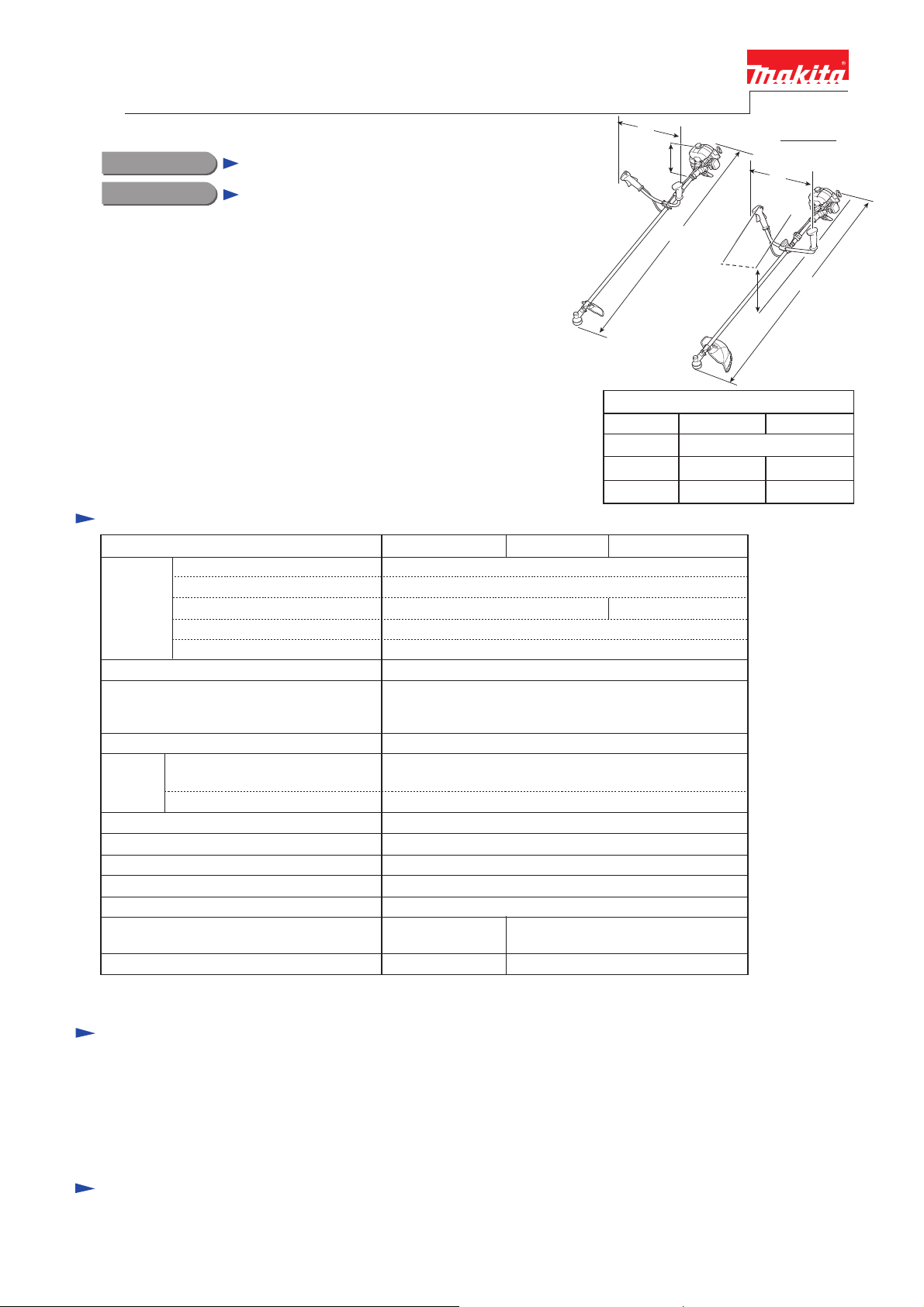
Length (L)
Width (W)
Height (H)
ˉ¹]
H
L
H
Dimensions: mm (")
RBC413U RBC414U
1,710 (67-3/8)
650 (25-5/8)
435 (17-1/8)
W
L
RBC414U,
RBC414UG
630 (24-3/4)
515 (20-1/4)
Standard equipment
Blade or Nylon head .......................................................1
Wrench 17-19 ..................................................................1
Hex wrench 4 ..................................................................1
Hex wrench 5 ..................................................................1
Note: The standard equipment for the tool shown above may vary by country.
Box wrench 17 ................................................................1
Shoulder strap assembly ..................................................1
Accessory bag .................................................................1
Safety goggles (for Slovenia only) ..................................1
Fuel mixture (for Vietnam only) .....................................1
Optional accessories
Double blade 305mm (12"), Triple blade 255mm (10"), Triple blade 305mm (12"), Star blade 230mm (9"),
Star blade 255mm (10"), 8-tooth blade 230mm (9"), 8-tooth blade 255mm (10"), Nylon cutting head (Bump & Feed Z5L),
Nylon cutting head (Ultra Auto 6L), Protector (for cutting blade only), Universal guard (=Protector),
Universal guard extension, Safety googles, Fuel mixture

P 2/ 17
Repair
CAUTION: Repair the machine in accordance with “Instruction manual” or “Safety instructions”.
[1] NECESSARY REPAIRING TOOLS
DescriptionCode No. Use for
Retaining ring pliers RT-2E for Internal ring1R006
Bearing plate1R022
Pipe ring1R023
Tachometer1R070 checking rpm of Engine
Crank shaft lock bolt1R155
Ignition checker1R181 checking ignition
1R219
1R269
1R311 Retaining ring pliers with Long bent nails
782235-2
Torque wrench shaft 7-23N·m
Ratchet head 9.5 (for 1R219)1R220
Bearing extractor
Flywheel puller1R364 removing Flywheel
Feeler gauge set1R366 adjusting Ignition coil/ Spark plug
Digital tester1R402 checking the continuity of electrical parts
Wire brush making Spark plug clean
Hex wrench 4 (standard equipment)783223-2
Wrench 17-19 (standard equipment)
removing/ assembling Retaining rings
removing Clutch drum complete from Ball bearing 6003LLU
assembling Ball bearing 6003LLU to Clutch drum completeBearing setting pipe 20-12.21R028
locking Piston (with Crank shaft)
removing Piston pinPiston pin punch1R200
tightening Bolts
removing Ball bearings
removing Fuel tube from nipple of Carburetor
removing Retaining rings R-26 and R-32 in Gear case assembly
removing Clutch drum complete
removing Spark plug
[2] GASKET
Once Gasket is removed:
(1) Replace Gasket with a new one.
(2) Clean up the mating surface where the gasket was installed to maintain its sealing performance.
[3] LUBRICANT/ ADHESIVE APPLICATION
(1) Apply 1g of Makita grease N No. 2 to Spiral spring in Recoil starter.
(2) When the inside of Gear case assembly is cleaned, supply 11g of Makita grease N No. 2 from the grease inlet.
(3) Apply 6g of Makita grease N No. 1 to the entire portion of Shaft complete in Shaft pipe complete.
[4] DISASSEMBLY/ ASSEMBLY
[4]-1. Warning
Follow the instructions described below in advance before repairing:
• Wear gloves.
• Remove the cutting tool from the unit, and if it is a saw blade, attach the blade cover to the blade.
• When the engine is hot from use, cool down the engine enough or you can get burned.
• Remove remaining fuel from Fuel tank and Carburetor completely. [FLAMMABLE MATERIAL KEEP FIRE AWAY]
• Remove Spark plug cap from Spark plug.
• Repair the engine on a stable workbench and in a clean workplace kept as free of dust and debris as possible.
• In order to avoid wrong reassembly, draw or write down where and how the parts are assembled, and what are the parts.
• It is also recommended to have boxes ready to keep disassembled parts by group.
• Handle the disassembled parts carefully. Clean and wash them properly.
• If some bolts and screws are too tight, use Impact driver.
• Tighten the bolts and the screws to the specified torque as shown in "[5] Tightening torque specifications".
• Each time after you mounted a main part of the engine such as the piston, check if it moves smoothly
without abnormal noise by manually turning the crankshaft.
• After completion of reassembly, check for loose parts or abnormal noise and vibration by manually turning the crankshaft.
Repair
[4] DISASSEMBLY/ ASSEMBLY
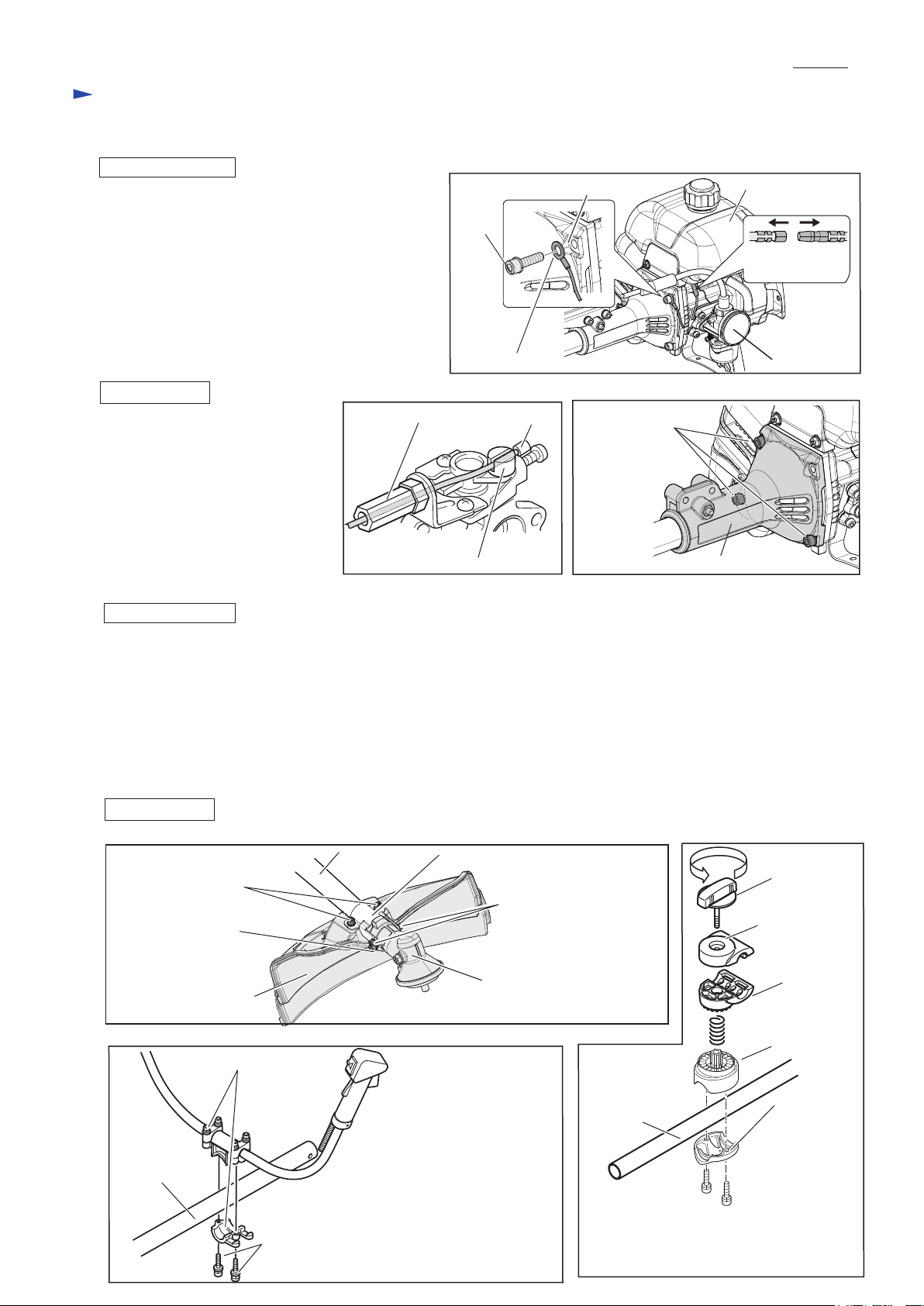
[4]-2. Engine and Shaft
DISASSEMBLING
(1) Remove M6x22 Hex socket head bolt that fastens
Earth terminal to Clutch case.
Disconnect Bullet terminals of Lead wires. (Fig. 1)
Note: If it is difficult to do the above steps, first of all,
remove Fuel tank from Engine.
(2) Remove Inner cable from Swivel of Carburetor,
then separate Control cable
from Adjust screw. (Fig. 2)
(3) Remove the rest of M6x22 Hex socket head bolts to
separate Engine from Clutch case. (Fig. 3)
Fig. 1
M6x22 Hex
socket
head
bolt
Earth terminal
P 3/ 17
Clutch case Fuel tank
Bullet terminals
of Lead wires
Carburetor
ASSEMBLING
Assemble by reversing
the disassembly procedure.
Fig. 2
Inner cable Adjust screw
Swivel
Fig. 3
M6x22 Hex socket
head bolt (with
spring washer)
(3 pcs.)
Clutch case
[4]-3. Protector assembly, Bike handle
DISASSEMBLING
(1) Remove two M6x30 Hex head bolts and Protector. (Fig. 4)
(2) Loosen M6x30 Hex socket head bolt on the neck of Gear case assembly, and then remove two M5x14 Hex socket head
screws. Pull out Gear case assembly from the end of Shaft pipe complete.
(3) [For RBC413U only] Remove two M6x30 Hex socket head bolts from Handle holder ass’y to separate Handle section
from Shaft pipe complete. (Fig. 5) Bike handle section can be disassembled.
[For RBC414U and RBC414UG only] Loosen Knob 57 to remove Handle holder from Shaft pipe complete.
Bike handle section can be disassembled.
Remove Pipe clamp from Shaft pipe complete by unscrewing two M6x25 Hex
socket head bolts. (Fig. 6)
ASSEMBLING
Fig. 4
M6x30 Hex socket head screw
(with spring washer and
flat washer) (2 pcs.)
M6x30 Hex socket head bolt
with flat washer and
spring washer
Assemble by reversing the disassembly procedure.
Shaft pipe
complete
Protector
Protector clamp
M5x14 Hex socket head
screw (with spring washer
and flat washer) (2 pcs.)
Gear case assembly
Fig. 6
Knob 57
Handle clamp
Handle holder
Fig. 5
Shaft pipe
complete
Handle holder ass’y
M6x30 Hex socket head bolt (with flat washer
and spring washer) (2 pcs.)
Shaft pipe
complete
Pipe holder
Pipe clamp
M6x25 Hex socket head bolt
(with spring washer) (2 pcs.)
Repair
[4] DISASSEMBLY/ ASSEMBLY
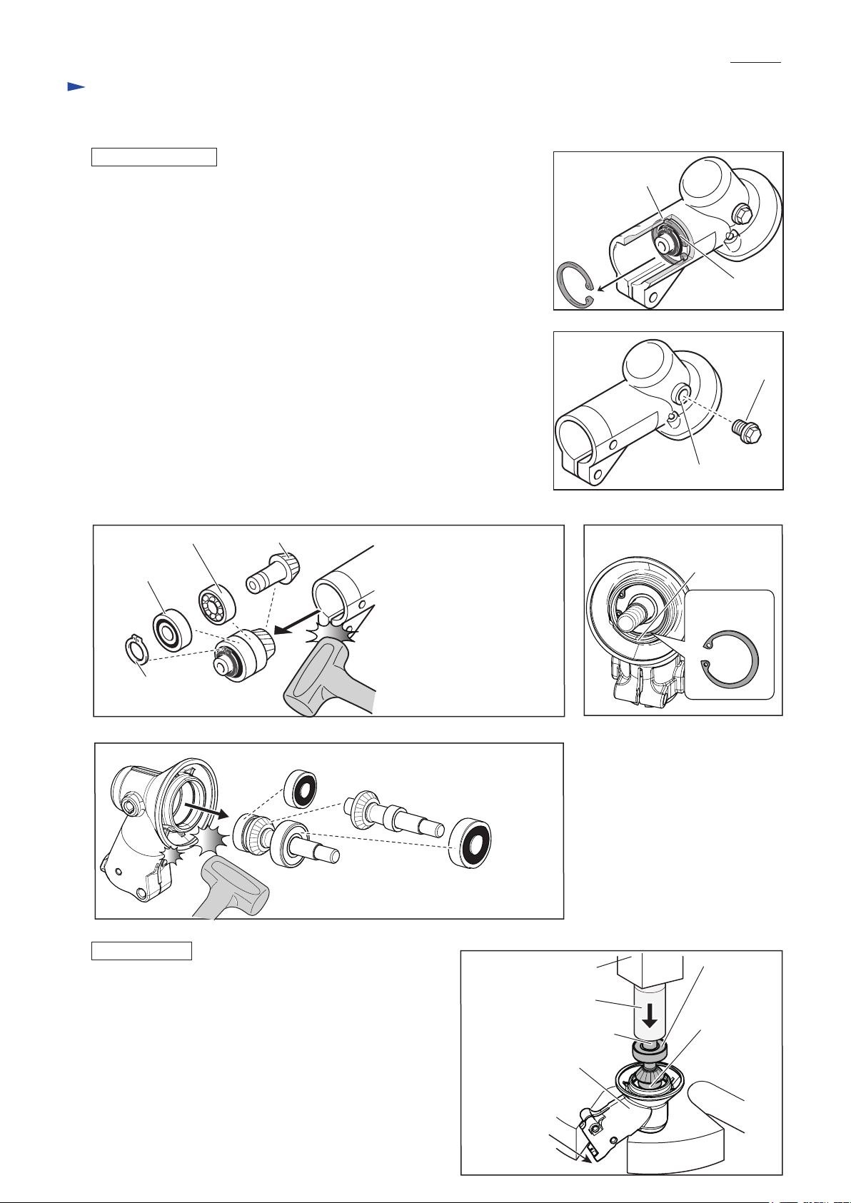
[4]-4. Gear case assembly
DISASSEMBLING
(1) Remove Gear case assembly from Pipe shaft complete. (see Fig. 4 of
the previous page.)
(2) Remove Retaining ring R-26 from the groove in Gear case assembly with
1R311. (Fig. 7)
(3) Remove M8x10 + Hex bolt that is the stopper of Grease inlet on Gear case
assembly. (Fig. 8)
(4) Remove an assembled part of Spiral bevel gear 13*, Ball bearing 6000ZZ,
Ball bearing 6000 and Retaining ring S-10 by tapping Gear case assembly
with Plastic hammer. (Fig. 9)
(5) Remove Retaining ring R-32 from the groove in Gear case assembly with
1R311. (Fig. 10)
(6) Remove an assembled part of Ball bearing 629ZZ, Cutter shaft complete**
and Ball bearing 6201DDU from Gear case assembly. (Fig. 11)
Note: • When it is difficult to remove the assembled part from Gear case
assembly, heat up Gear case assembly with heat gun or like and then
try the step (5)/ (6) again.
• Spiral bevel gear 13* and Cutter shaft complete** cannot be supplied
individually. Order “Cutter shaft set” from us.
(7) Disassemble their assembled parts by using 1R269 and Arbor press.
Fig. 9
Ball bearing 6000
Ball bearing
6000ZZ
Spiral bevel gear 13* (The component of Cutter shaft set)
P 4/ 17
Fig. 7
Groove in Gear
case assembly
Retaining ring
R-26
Fig. 8
M8x10
+ Hex bolt
Grease inlet
Fig. 10
Groove in Gear
case assembly
Retaining
ring R-32
Retaining
ring S-10
Fig. 11
Ball bearing 629ZZ
ASSEMBLING
Assemble by reversing the disassembly procedure.
Note: • Receive Gear case assembly with the U-shape table of
Arbor press, then press down Ball bearing 6201DDU
with 1R031 to set Cutter shaft complete in place.
(Fig. 12)
• Ball bearing 6000ZZ must be close to Retaining ring
S-10. (See Fig. 9)
• When the gear room is cleaned up, apply 11g Makita
grease N No.2 into Gear case assembly from the grease
inlet. (See Fig. 8)
Cutter shaft complete**
(The component of Cutter shaft set)
Ball bearing 6201DDU
Fig. 12
Arbor press
Cutter shaft complete
Gear case assembly
U-shape table
of Arbor press
Ball bearing
6201DDU
1R031
Ball bearing
629ZZ
P 5/ 17
Repair
[4] DISASSEMBLY/ ASSEMBLY
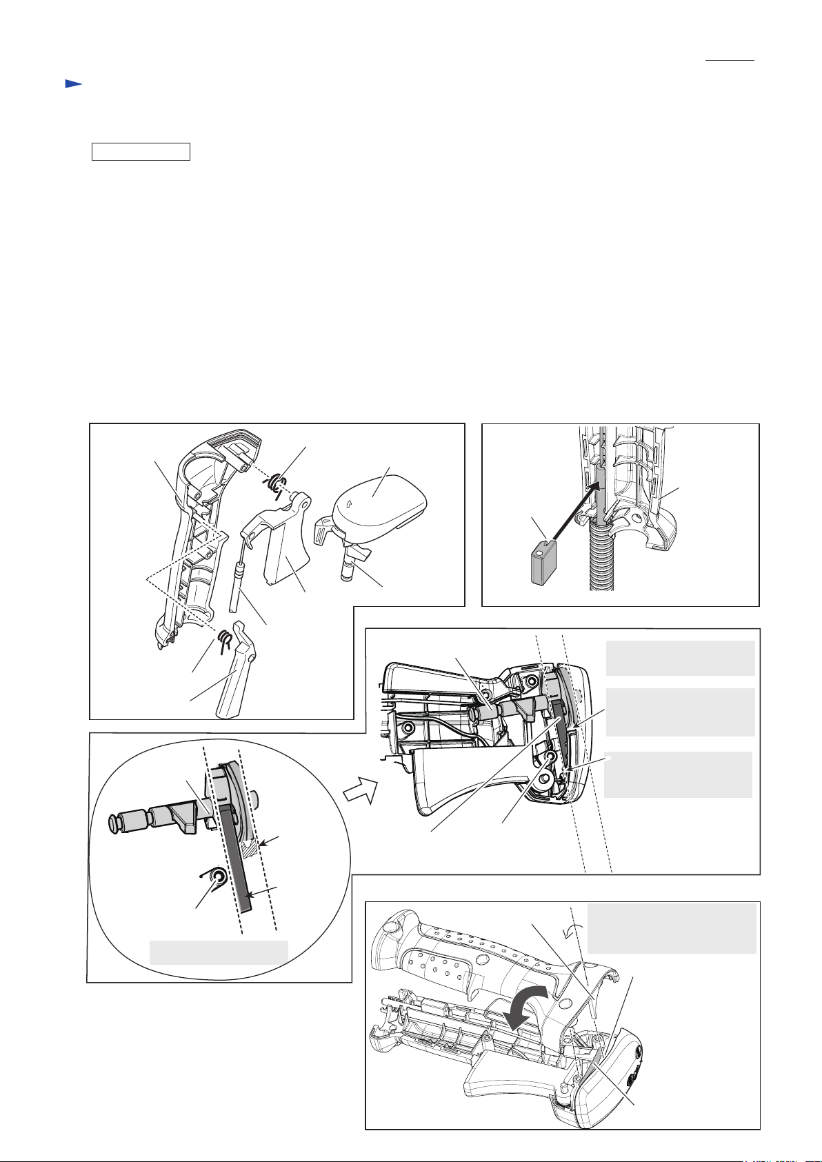
[4]-5. Control lever assembly
ASSEMBLING
See Fig. 13.
(1) Hook Control cable to Throttle lever.
Assemble Switch lever and Leaf spring to Switch cover.
(2) Assemble Throttle lever, Lock off lever and Switch cover to Lever case L in order while setting the following parts
in place:
• Torsion spring 11 to Throttle lever
• Torsion spring 7 to Lock off lever
(3) Fix Control cable in Cable holder when setting Control cable in place as drawn in Fig. 14.
(4) If Lever case R is assembled straight to Lever case L, Leaf spring will be hooked with the bosses of Lever cases L/R
or the curve rib of the Lever case L. Therefore, do the following steps. as drawn in Figs. 15 and 16.
1. Set Leaf spring horizontal to the round shape of Switch lever so as to place the spring to the bottom of Lever case L
between Boss of Lever case L and the curve rib installation position. (Fig. 15)
2. While retaining Leaf spring in between the curve rib and Boss, turn Lever case R counterclockwise carefully to
mate it with Lever case L without pinching. (Fig. 16)
Fig. 13
Lever case L
Torsion spring 7
Lock off lever
Switch lever
Torsion spring 11
Throttle lever
Control cable
Switch cover
Switch lever
Fig. 15
Switch lever
Fig. 14
Lever case L
Cable holder
Set Leaf spring horizontal
to Switch lever.
Insert the curve rib of
Lever case R here so as
not to pinch Leaf spring.
Insert the end portion of
Leaf spring firmly to the
bottom of Lever case L.
Boss of Lever case L
Leaf spring position
Curve rib
installation
position
Leaf spring
Leaf spring
Fig. 16
Boss
Position of Leaf spring
Curve rib
Round shape of
Switch lever
While turning Lever case R
along with this axis, assemble
to Lever case L carefully.
Curve rib
installation
position
Leaf spring
Repair
[4] DISASSEMBLY/ ASSEMBLY
[4]-6. Clutch
DISASSEMBLING
Note: • Clutch can be easily removed with Impact driver without holding the piston.
• Do not remove Spark plug as compressed air resistance has to be used for the disassembling.
• Plug cap with Plug cap spring has to be removed from Spark plug.
(1) Remove the clutch section by unscrewing two M8 shoulder hex bolts.
Then, remove M6x14 Hex head bolt with Impact driver. (Fig. 17)
(2) Install 1R364 on Holder then screw two bolts into Holder as drawn in Fig. 18
instead of M8 Shoulder hex bolts. Holder is removed from Engine.
Fig. 17
M8 Shoulder hex bolt (2pcs.)
Fig. 18
P 6/ 17
1R364
M6x14 Hex head bolt
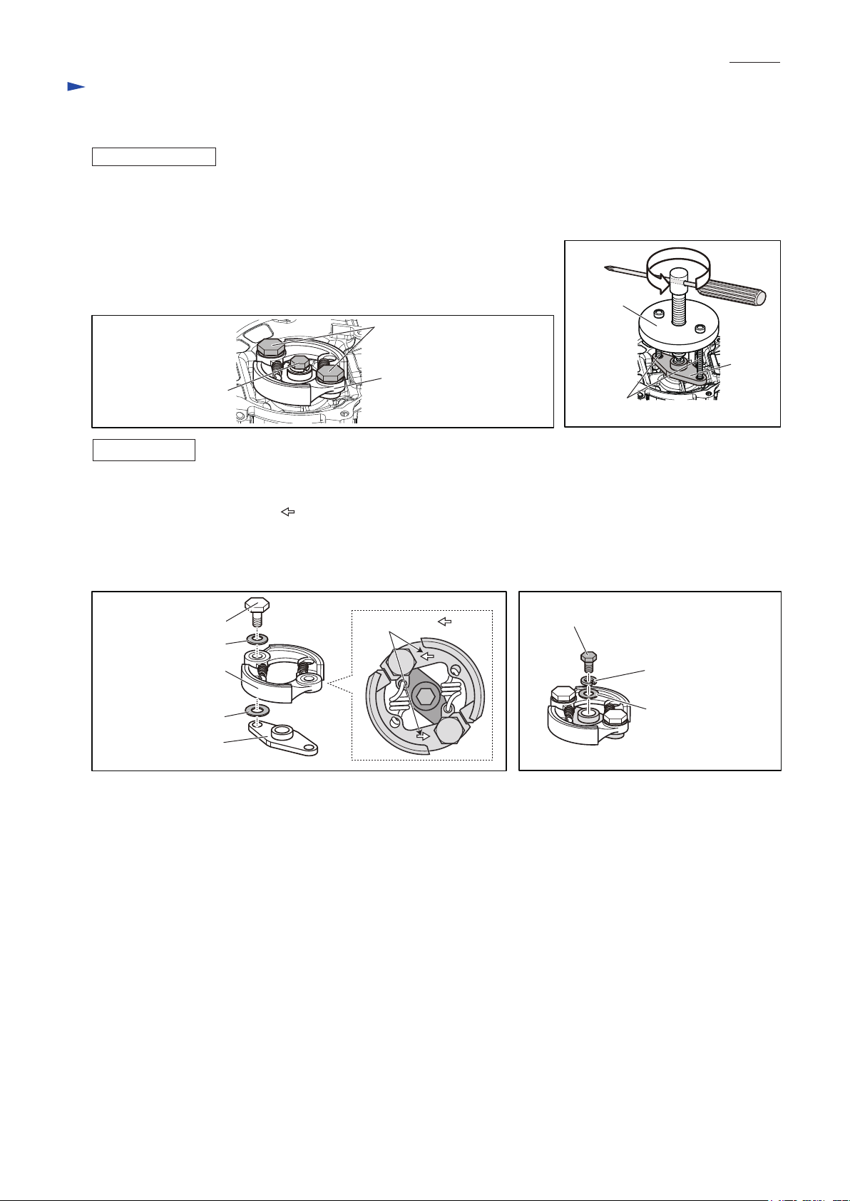
ASSEMBLING
(1) After putting the clutch section (two Clutch shoes and two Springs), two Wave washers 10 and two Flat washers 8
on Holder, tighten them with two M8 shoulder hex bolts. (Fig. 19)
Note: Face the marking of “ ” to the outside as drawn in Fig. 19A.
(2) Put the assembled part, Flat washer 6, Spring washer 6 and M6x14 Hex head bolt on the crank shaft of Engine,
then tighten the bolt to 12 N·m with 1R219, 1R220 while inserting 1R155 into Spark plug hole to lock Piston
to prevent the rotation of the crank shaft. (Fig. 20)
Fig. 19
M8 Shoulder hex bolt
Wave washers 10
Clutch section
Flat washers 8
Holder
Clutch section
Fig. 19A
marking of “ ”
M8 bolts
(the components of 1R364)
Fig. 20
M6x14 Hex head bolt
Spring washer 6
Flat washer 6
Holder
 Loading...