

Page 1
T
ECHNICAL INFORMATION
PRODUCT
P 1/ 15
Models No.
Description
RBC411U
Petrol Brushcutter
CONCEPT AND MAIN APPLICATIONS
Model RBC411U is Petrol brushcutter developed based on Model RBC411
powered by 40.2 cm³ 2-stroke engine; therefore, the engine for this model is not
complied with well-known exhaust emission regulations.
The development concept of this model is to increase maneuverability, while
providing a cost advantage with newly designed Shaft section.
Its other features are:
• Symmetric design handle bar
• Ergonomic grip for higher maneuverability
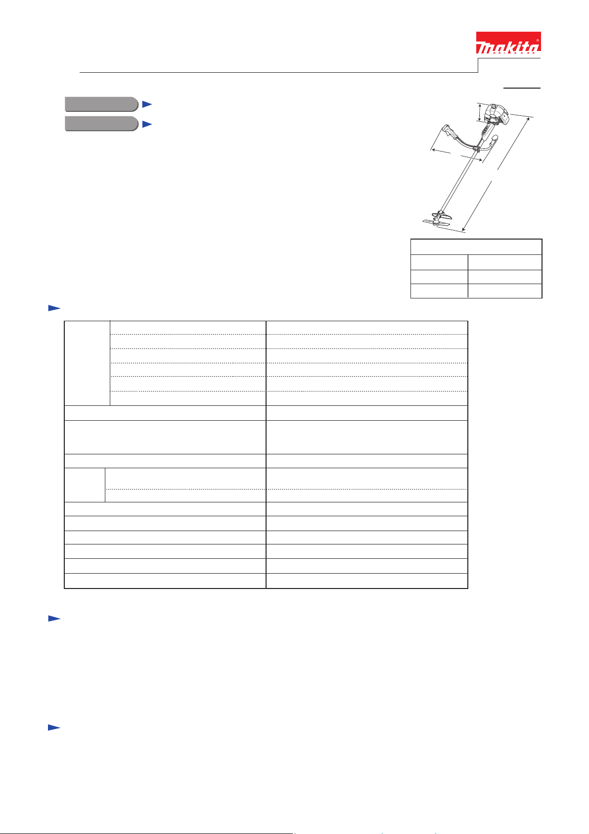
Specification
Displacement: cm³
Engine
Compliance with main exhaust
emission regulations; CARB Tier 3,
EPA Phase 2, EU Stage 2
Carburetor
Starting
system
Starting system Recoil starter
Fuel tank capacity: L
Primer pump No
Spindle thread size
Handle style
Net weight*: kg (lbs)
Fuel
Max. output: kW (PS) 1.4 (2.0) [at 7,000 min.
Max. torque: N.m
ˉ¹ = rpm
Rapid start
(Spring-assisted recoil starter)
Decompression valve
Mixed gasoline
2.2 [at 5,000 min.
M10x1.25, Left-handed
Symmetric design bike handle
2-strokeType
40.2
10,000Max. speed at no load: min.ˉ¹ = rpm
6,800Max. spindle speed at no load: min.
No
Float type
No
No
1.1
7.3 (16)
H
W
Dimensions: mm (")
Length (L) 1,710 (67-1/2)
Width (W)
Height (H)
ˉ¹]
ˉ¹]
670 (26-3/8)
L
430 (17)
* Dry weight, without guard, cutting tool and shoulder harness
Standard equipment
Double blade 305mm (12") ................................................................ 1
Tool kit
(inc. Socket wrench 17-19, Hex wrench 4 and Hex wrench 5) .......... 1
Shoulder harness with double shoulder straps .................................... 1
Accessory bag ..................................................................................... 1
Note: The standard equipment for the tool shown above may vary by country.
Optional accessories
Triple blade 255mm (10"), Triple blade 305mm (12"), Star blade 230mm (9"), Star blade 255mm (10"),
Double blade 305mm (12"), Eddy blade (8-tooth blade) 230mm (9"), Eddy blade (8-tooth blade) 255mm (10"),
Saw blade 230mm (9"), Saw blade 255mm (10"), Nylon cutting head (Bump & Feed Z5L),
Nylon cutting head (Ultra Auto 6L), Protector (for cutting blade only), Universal guard (=Protector),
Universal guard extension
Page 2

P 2/ 15
Repair
CAUTION: Repair the machine in accordance with “Instruction manual” or “Safety instructions”.
[1] NECESSARY REPAIRING TOOLS
DescriptionCode No. Use for
Retaining ring pliers ST-2 for External ring1R004 removing/ assembling Retaining rings
Retaining ring pliers RT-2E for Internal ring1R006
Bearing plate1R022
Pipe ring1R023
Air density tester1R127 diagnosing Carburetor
Crank shaft lock bolt1R155
1R219
1R269
1R311 Retaining ring pliers with Long bent nails
Torque wrench shaft 7-23N·m
Ratchet head 9.5 (for 1R219)1R220
Bearing extractor
Flywheel puller1R364 removing Flywheel
Feeler gauge set1R366 adjusting Ignition coil/ Spark plug
Wire brush making Spark plug clean
removing/ assembling Retaining rings
removing Clutch drum complete from Ball bearing 6003LLU
assembling Ball bearing 6003LLU to Clutch drum completeBearing setting pipe 20-12.21R028
locking Piston (with Crank shaft)
removing Piston pinPiston pin punch1R200
tightening Bolts
removing Ball bearings
removing Fuel tube from nipple of Carburetor
removing Retaining rings R-26 and R-32 in Gear case assembly
[2] GASKET
Once Gasket is removed:
(1) Replace Gasket with a new one.
(2) Clean up the mating surface where the gasket was installed to maintain its sealing performance.
[3] LUBRICANT/ ADHESIVE APPLICATION
(1) Apply 1g of Makita grease N No. 2 to Spiral spring in Recoil starter.
(2) When the inside of Gear case assembly is cleaned, supply 11g of Makita grease N No. 2 from the grease inlet.
(3) Apply 6g of Makita grease N No. 1 to the entire portion of Shaft complete in Shaft pipe complete.
[4] DISASSEMBLY/ ASSEMBLY
[4]-1. Warning
Follow the instructions described below in advance before repairing:
• Wear gloves.
• Remove the cutting tool from the unit, and if it is a saw blade, attach the blade cover to the blade.
• When the engine is hot from use, cool down the engine enough or you can get burned.
• Remove remaining fuel from Fuel tank and Carburetor completely. [FLAMMABLE MATERIAL KEEP FIRE AWAY]
• Remove Spark plug cap from Spark plug.
• Repair the engine on a stable workbench and in a clean workplace kept as free of dust and debris as possible.
• In order to avoid wrong reassembly, draw or write down where and how the parts are assembled, and what are the parts.
• It is also recommended to have boxes ready to keep disassembled parts by group.
• Handle the disassembled parts carefully. Clean and wash them properly.
• If some bolts and screws are too tight, use Impact driver.
• Tighten the bolts and the screws to the specified torque as shown in "[5] Tightening torque specifications".
• Each time after you mounted a main part of the engine such as the piston, check if it moves smoothly
without abnormal noise by manually turning the crankshaft.
• After completion of reassembly, check for loose parts or abnormal noise and vibration by manually turning the crankshaft.
Page 3
Repair
[4] DISASSEMBLY/ ASSEMBLY
[4]-2. Engine and Shaft
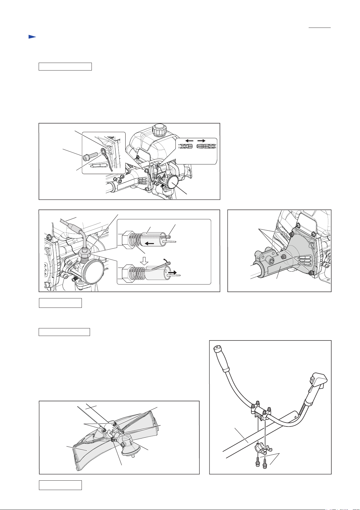
DISASSEMBLING
(1) Remove M6x22 Hex socket head bolt that fastens Earth terminal to Clutch case complete.
Disconnect Bullet terminals of Lead wires. (Fig. 1)
(2) Loosen Mixing cap of Carburetor, then remove Piston valve from Carburetor. Push Piston valve against
the spring force to separate the cable end from Piston valve. (Fig. 2)
(3) Remove the rest of M6x22 Hex socket head bolts to separate Engine from Clutch case. (Fig. 3)
Fig. 1
Clutch case complete
M6x22 Hex
socket head bolt
Bullet terminals
of Lead wires
Earth terminal
Carburetor
P 3/ 15
Fig. 2 Fig. 3
Control cable
ASSEMBLING
Assemble by reversing the disassembly procedure.
Mixing cap
Piston valve The end of
Control cable
Spring
M6x22 Hex
socket head bolt
(3 pcs.)
[4]-3. Protector assembly, Bike handle
DISASSEMBLING
(1) Remove two M6x30 Hex head bolts (A) and Protector. (Fig. 4)
(2) Loosen M6x30 Hex socket head bolt (B) on the neck of
Gear case assembly, and then remove two M5x14 Hex socket
head screws.
Pull out Gear case assembly from the end of Shaft pipe complete.
(3) Remove two M6x30 Hex socket head bolts to separate Handle
section from Shaft pipe complete. (Fig. 5)
Fig. 4
M6x30 Hex
Shaft pipe complete
socket head
screw (2 pcs.): A
Protector
M6x30 Hex socket head bolt: B
Protector clamp
M5x14 Hex
socket head
screw (2 pcs.)
Gear case assembly
Fig. 5
Shaft pipe
complete
Clutch case complete
M6x30 Hex
socket head
bolt (2 pcs.)
ASSEMBLING
Assemble by reversing the disassembly procedure.
Page 4
Repair
[4] DISASSEMBLY/ ASSEMBLY
[4]-4. Gear case assembly
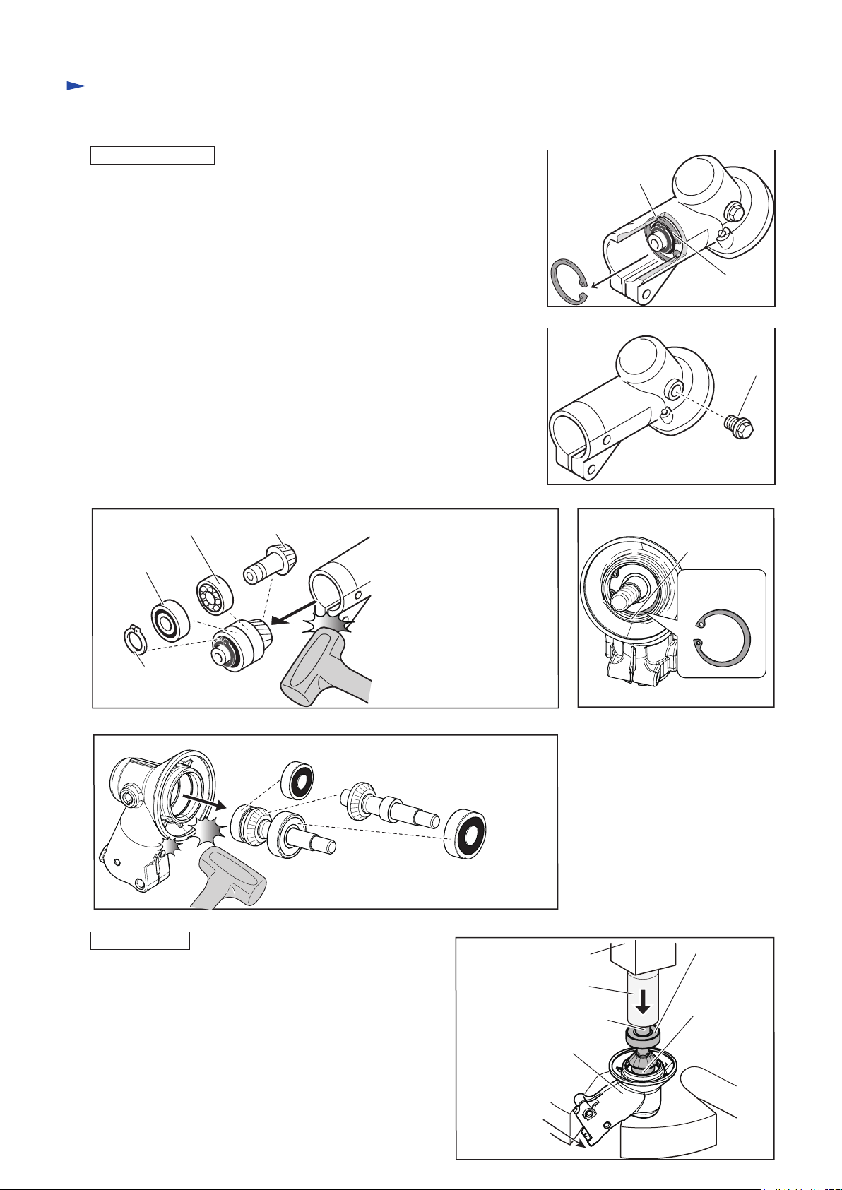
DISASSEMBLING
(1) Remove Gear case assembly from Pipe shaft complete. (see Fig. 4)
(2) Remove Retaining ring R-26 from the groove in Gear case assembly with
1R311. (Fig. 6)
(3) Remove M8x10 + Hex bolt that is the stopper of Grease inlet on Gear case
assembly. (Fig. 7)
(4) Remove an assembled part of Spiral bevel gear 13*, Ball bearing 6000ZZ,
Ball bearing 6000 and Retaining ring S-10 by tapping Gear case assembly
with Plastic hammer. (Fig. 8)
(5) Remove Retaining ring R-32 from the groove in Gear case assembly with
1R311. (Fig. 9)
(6) Remove an assembled part of Ball bearing 629ZZ, Cutter shaft complete**
and Ball bearing 6201DDU from Gear case assembly. (Fig. 10)
Note: • When it is difficult to remove the assembled part from Gear case
assembly, heat up Gear case assembly with heat gun or like and then
try the step (5)/ (6) again.
• Spiral bevel gear 13* and Cutter shaft complete** cannot be supplied
individually. Order “Cutter shaft set” from us.
(7) Disassemble their assembled parts by using 1R269 and Arbor press.
P 4/ 15
Fig. 6
Groove in Gear
case assembly
Retaining ring
R-26
Fig. 7
M8x10
+ Hex bolt
Fig. 8
Ball bearing 6000
Ball bearing
6000ZZ
Retaining
ring S-10
Fig. 10
Spiral bevel gear 13* (The component of Cutter shaft set)
Ball bearing 629ZZ
Cutter shaft complete**
(The component of Cutter shaft set)
Ball bearing 6201DDU
Fig. 9
Groove in Gear
case assembly
Retaining
ring R-32
ASSEMBLING
Assemble by reversing the disassembly procedure.
Note: • Receive Gear case assembly with the U-shape table of
Arbor press, then press down Ball bearing 6201DDU
with 1R031 to set Cutter shaft complete in place.
(Fig. 11)
• Ball bearing 6000ZZ must be close to Retaining ring
S-10. (See Fig. 8)
• When the gear room is cleaned up, apply 11g Makita
grease N No.2 into Gear case assembly from the grease
inlet. (See Fig. 7)
Fig. 11
Arbor press
Cutter shaft complete
Gear case assembly
U-shape table
of Arbor press
Ball bearing
6201DDU
1R031
Ball bearing
629ZZ
Page 5
Repair
[4] DISASSEMBLY/ ASSEMBLY
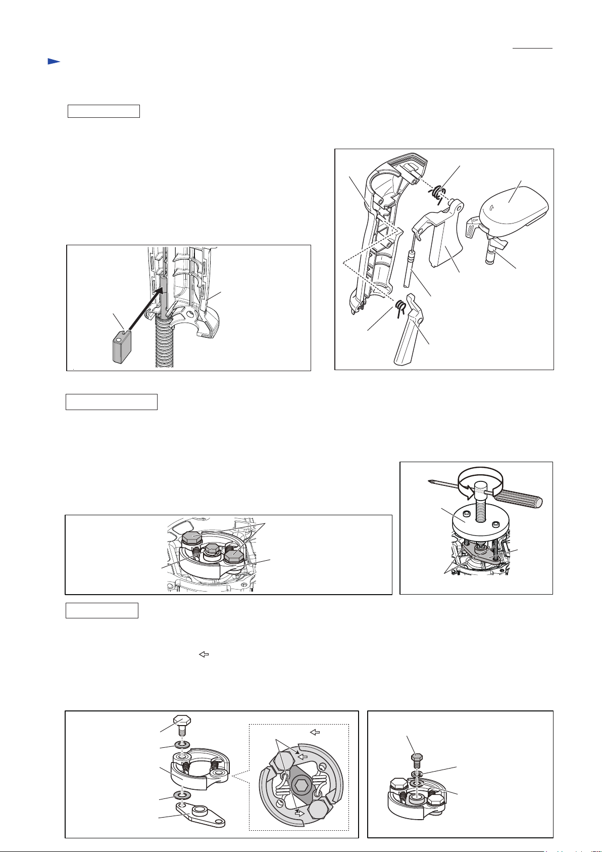
[4]-5. Control lever assembly
ASSEMBLING
See Fig. 12.
(1) Hook Control cable to Throttle lever.
Assemble Switch lever and Leaf spring to Switch cover.
(2) Assemble Throttle lever, Lock off lever and Switch cover to
Lever case L in order while setting the following parts in place:
• Torsion spring 11 to Throttle lever
• Torsion spring 7 to Lock off lever
(3) Fix Control cable with Cable holder when setting Control
cable in place as drawn in Fig. 13.
Fig. 13
Fig. 12
Lever
case L
P 5/ 15
Torsion spring 11
Switch cover
Throttle lever
Lever case L
Cable holder
Torsion
spring 7
Control cable
Lock off lever
[4]-6. Clutch
DISASSEMBLING
Note: • Clutch can be easily removed with Impact driver without holding the piston.
• Do not remove Spark plug as compressed air resistance has to be used for the disassembling.
• Plug cap with Plug cap spring has to be removed from Spark plug.
(1) Remove the clutch section by unscrewing two M8 shoulder hex bolts.
Then, remove M6x14 Hex head bolt with Impact driver. (Fig. 13)
(2) Install 1R364 on Holder then screw two bolts into Holder as drawn in Fig. 14
instead of M8 Shoulder hex bolts. Holder is removed from Engine.
Fig. 13
M8 Shoulder hex bolt (2pcs.)
Clutch section
M6x14 Hex head bolt
Fig. 14
1R364
M8 bolts
(the components of 1R364)
Switch lever
Holder
ASSEMBLING
(1) After putting the clutch section (two Clutch shoes and two Springs), two Wave washers 10 and two Flat washers 6
on Holder, tighten them with two M8 shoulder hex bolts. (Fig. 15)
Note: Face the marking of “ ” to the outside as drawn in Fig. 15A.
(2) Put the assembled part, Flat washer, Spring lock washer and M6x14 Hex head bolt on the crank shaft of Engine,
then tighten the bolt to 12 N·m with 1R219, 1R220 while inserting 1R155 into Spark plug hole to lock Piston
to prevent the rotation of the crank shaft. (Fig. 16)
Fig. 15
M8 Shoulder hex bolt
Wave washers 10
Clutch section
Flat washers 6
Holder
Fig. 15A
marking of “ ”
Fig. 16
M6x14 Hex head bolt
Spring lock washer
Flat washer
Page 6

P 6/ 15
Repair
[4] DISASSEMBLY/ ASSEMBLY
[4]-7. Clutch drum complete
DISASSEMBLING
(1) Remove M6x14 Hex head bolt and Flat washer 6 from Clutch drum complete while inserting Hex wrench into
Gear case assembly and pretighten Receive washer and Clamp washer with M10 Nut to prevent the rotation of
Shaft complete. (Figs. 17 and 18)
(2) Unlock Retaining ring R-35 in the groove of Clutch case complete with 1R006 through the hole of Clutch drum
complete. (Fig. 18)
(3) Tap the corners of Clutch case complete carefully with Plastic hammer to remove Clutch drum complete. (Fig. 19)
(4) Separate Damper and Shaft complete from Clutch drum complete. (Fig. 20)
(5) Remove Retaining ring S-17 from Clutch drum complete with 1R004. (Fig. 21)
(6) Remove Ball bearing 6003LLU from Clutch drum complete with 1R022, 1R023 and Arbor press. (Fig. 22)
Fig. 17
Hex wrench
Clamp washer
Plastic
hammer
Clutch drum
complete
Fig. 22
Gear case assembly
Receive washer
M10 Nut
Clutch case complete
Fig. 20
Fig. 18
Hole of Clutch
drum complete
Flat washer 6
M6x14
Hex head bolt
Clutch drum complete Clutch case complete
Fig. 21Fig. 19
Clutch drum complete
Shaft complete
DumperClutch drum complete
Retaining ring
R-35
Retaining ring
S-17
Groove
1R023
1R022 Arbor press
Ball bearing 6003LLU
Ball bearing 6003LLU
Retaining ring R-35
Clutch drum complete
Page 7

P 7/ 15
Repair
[4] DISASSEMBLY/ ASSEMBLY
[4]-7. Clutch drum complete (cont.)
ASSEMBLING
(1) After putting Retaining ring R-35 on the center of Clutch drum complete, pressfit Ball bearing 6003LLU in place of
Clutch drum complete with 1R028. (Fig. 23)
Fit Retaining ring S-17 into the groove of Clutch drum complete with 1R004. (See Fig. 21)
(2) Assemble Shaft complete with Damper to Clutch drum complete so as to mate the connecting portions of Shaft
complete and Clutch drum complete in Damper. (Fig. 24)
Assemble the assembled part to Clutch case complete by tapping the center of Clutch drum complete carefully with
Plastic hammer. (Fig. 25)
(3) Fit Retaining ring R-35 into the groove of Clutch case complete with 1R006 through the hole of Clutch drum complete,
then set M6x14 Hex bolt and Flat washer 6 on Clutch drum complete while inserting Hex wrench into Gear case
assembly and pretighten Receive washer and Clamp washer with M10 Nut to prevent the rotation of Shaft complete.
(See Figs. 18 and 17)
Note: Apply ThreeBond 1342/ Loctite 242 to the thread of M6x14 Hex bolt.
Fig. 23
1R028
Fig. 24
Retaining ring R-35
Retaining ring S-17
Connecting portion of Clutch drum
complete
Retaining ring R-35
Ball bearing
6003LLU
Connecting portion of
Shaft completeDamperBall bearing 6003LLU
Fig. 25
Clutch drum complete Clutch case complete
Plastic hammer
Clutch drum complete
Page 8

P 8/ 15
Repair
[4] DISASSEMBLY/ ASSEMBLY
[4]-8. Ignition
CHECK OF PLUG CAP (SPRING)
(1) Remove Plug cap from Spark plug, then detect the continuity between Plug cap spring in Plug cap and Earth terminal
of Ignition coil.
It is the normal condition when Tester shows 2.45kΩ±10%. (Fig. 26)
(2) In case of no continuity or unstable continuity, check the connection between Plug cap spring and Ignition coil as follows:
(A) Spray the lubricant in Plug cap, then pull out Plug cap spring together with Ignition cable using Pliers. (Fig. 27)
(B) In case no connection or inconsistent connection, then check the condition of Plug cap and Plug cap spring.
Reassemble them or replace them if they are disorder.
(C) Insert the end of Plug cap spring into Ignition cable then return them back to the inside of Plug cap carefully so as
not to be disconnected.
(D) Check Plug cap and Plug cap spring again according to the step of (1) to avoid poor connection causing the poor
sparks of Spark plug.
Fig. 26 Fig. 27
Plug cap
Tester
Plug cap spring
Pliers
Earth terminal
CHECK OF SPARK PLUG
(1) Remove Plug cap with Plug cap spring from Spark plug, then remove
Spark plug with Wrench 17-19 (standard equipment).
Note: When the spark area is wet with Fuel, wipe it away with a cloth and dry it
by air blow.
(2) Clean carbonized materials on Insulated part for sparking with a wire brush.
(3) Do fine adjustment of Spark plug as drawn in Fig. 28.
Insert 0.7mm thickness gauge of 1R366 to the clearance and adjust the leg of
Spark plug carefully.
(4) Install Plug cap with Plug cap spring on Plug and connect the plug screw part
to a metal part of Engine, then pull Starter rope slowly.
The sparks can be seen when starter rope is pulled.
(5) When the sparks can not be seen, refer to “CHECK OF PLUG CAP (SPRING)”
in this page to detect the continuity. If required, replace Plug and recheck the sparks
through the above process.
Ignition cable
Fig. 28
0.6 up to 0.7 mm
Page 9

P 9/ 15
Repair
[4] DISASSEMBLY/ ASSEMBLY
[4]-8. Ignition (cont.)
REMOVING OF IGNITION COIL
(1) Remove M5x50 Hex socket head bolt and two M5x22 Hex socket head bolts (with washers and super lock washers)
and four M5x14 Pan head screws (with washers and spring lock washers), and then separate Blower housing,
Muffler cover and Cylinder cover from the machine. (Figs. 29 and 30)
(2) Before removing Ignition coil, pull out
Cable terminal. (Fig. 31)
(3) Remove two M5x22 Hex socket head bolts
to separate Ignition coil from Crank case
assembly. (Figs. 31 and 32)
Fig. 29
M5x50 Hex socket
head bolt
Blower housing
(See Fig. 30 for
the appearance
viewed from
Cylinder cover.)
Recoil starter
assembly
Fig. 30
Cylinder cover
M5x14 Pan head
screw (2 pcs.)
M5x14 Pan head screw
ASSEMBLING OF IGNITION COIL
See Fig. 32.
(1) While attaching 0.45mm thickness gauge of 1R366 to
the magnet portion of Flywheel, set Ignition coil in place.
(2) Remove the thickness gauge.
Then, turn Flywheel by hand to check whether it turns smoothly
without being stuck.
Muffler cover
M5x22 Hex socket
head bolt (2 pcs.)
Fig. 31
Cable terminal
M5x22 Hex socket head bolt (2 pcs.)
Fig. 32
M5x22 Hex socket head bolt
Muffler cover
M5x14 Pan head screw
Ignition coil
Flywheel
Ignition coil
Crank case
assembly
0.45mm thickness
gauge of 1R366
Flywheel
Page 10

P 10/ 15
Repair
[4] DISASSEMBLY/ ASSEMBLY
[4]-9. Flywheel
Note: • Flywheel can be easily removed with Impact driver without holding the piston.
• Do not remove Spark plug as compressed air resistance in Cylinder has to be used for the disassembling.
• Plug cap with Plug cap spring has to be removed from Spark plug to prevent Engine from running.
DISASSEMBLING
(1) Turn M6x16 Hex socket head bolt on the center of Flywheel counterclockwise using Cordless impact driver. (Fig. 33)
(2) Install 1R364 on Flywheel then screw two M6 bolts of 1R364 into Flywheel as drawn in Fig. 34.
Flywheel is removed from Engine.
Important: Screw two M6 bolts evenly.
Fig. 33 Fig. 34
M6x16 Hex socket head bolt
1R364
Thread holes to screw
M6 bolts of 1R364
(Refer to Fig. 31.)
ASSEMBLING
(1) Wipe off the grease and oil from Crank shaft. (Fig. 35)
(2) Put Woodruff key 3 into Crank shaft, then align the key
groove of Flywheel to Crank shaft with the key. (Fig. 35)
(3) Screw M6x16 Hex socket head bolt with Spring lock washer
to Crank shaft by turning them clockwise by hand.
(4) Tighten M6x16 Hex socket head bolt about two seconds
using Cordless impact driver.
Screwdriver
M6 bolt of
1R364
(2 pcs.)
Fig. 35
Key groove of Flywheel’s hole
Woodruff key 3
Wipe off the grease and
oil from Crank shaft.
Crankshaft
(in Crank case assembly)
Page 11

P 11/ 15
Repair
[4] DISASSEMBLY/ ASSEMBLY
[4]-10. Recoil starter assembly
DISASSEMBLING
(1) Remove Recoil starter assembly from Engine by unscrewing four
M5x14 Pan head screws.
(2) Pull the rope one turn of Reel, then, Hook the rope with the notch of
Reel and turn the reel clockwise until Spiral spring loses the tension.
(Fig. 36)
Note: Be careful. Reel is revolved by the recoil force of Spiral spring.
(3) Loosen M6x20 Tapping screw to disassemble Recoil starter
assembly. (Fig. 37)
Note: Be careful when removing this screw as there is a possibility that
Spiral spring pops out.
(4) Untie the knot of the rope in Reel and remove the rope from Reel.
ASSEMBLING
(1) When Spiral spring pops out of Reel:
- Set the one end of Spiral spring in the hook on the periphery side in the Reel.
- Rewind the spring counterclockwise toward the center of circle. (Fig. 38)
(2) Apply a little amount of Makita grease N No.2 to the spring.
(3) Make a knot on the new rope end and pass it through Reel and Base of
Starter case assembly, then connect the other end to Starter knob. (Fig. 39)
Refer to Fig. 40 how to make a knot of the rope.
(4) Wind the rope around Reel two or three turns.
(5) While turning Reel counterclockwise, fit it into the base of Starter case
assembly and set Spiral spring end into the hook on inside of the base.
(Figs. 39)
Note: This should be fixed without force.
(6) Secure Reel with M6x20 set screw. (Fig. 37)
Swing arm has to be passed through the groove of Reel.
Important: In case Reel turning is not smooth after tightening M6x20 Set screw, Reel is not properly fixed to Starter case.
Repeat the step (5) so that Reel can revolves smoothly even after M6x20 Set screw is completely tightened.
(7) Hook the rope in the notch of Reel while straining the rope, then turn Reel counterclockwise. (Fig. 41)
When the rope is removed from the notch, Reel winds the rope with spring recoil force. Repeat the step until
the rope slacks are cleared.
Fig. 36
M6x20
Set screw
Fig. 37
Fig. 38
M6x20
Reel
Tapping screw
Hook in Reel
for Spiral spring
Notch of Reel
Reel
Fig. 39 Fig. 40
Base of Recoil starter assembly
Fig. 41
Hook in Base of Recoil starter
Reel
assembly to assemble Spiral spring
Approx. 10mm
Approx. 10mm
Notch of Reel
Page 12

Repair
[4] DISASSEMBLY/ ASSEMBLY
[4]-11. Air cleaner assembly, Carburetor
DISASSEMBLING
P 12/ 15
(1) Remove Air cleaner cover by unscrewing
M5x20 Pan head screw. (Fig. 42)
(2) Remove Element, then separate Air cleaner plate
from Carburetor by unscrewing two M5x14 Pan
head screws. (Fig. 42)
(3) Remove Control cable and Bullet terminals of
Lead wires as drawn in Figs. 1 and 2.
(4) Unscrew M5x5 Wing nut under Float body to
drain the gasoline in Carburetor. (Fig. 43)
(5) Pull out Fuel tube from the nipple Carburetor
with 1R311. (Fig. 44)
(6) Remove Carburetor from Engine by unscrewing
two M5x58 Pan head screws. (Fig. 45)
Fig. 43 Fig. 45Fig. 44
Carburetor
Float body
M5x5
Wing nut
Tray to receive
Grease
Fig. 42
M5x14 Pan head
screw (2 pcs.)
Fuel tube
Nipple of
Carburetor
1R311
Air cleaner plate
Air cleaner cover
M5x20 Pan head screw
Element
Carburetor
M5x58
Pan head
screw (2 pcs.)
Page 13

P 13/ 15
Repair
[4] DISASSEMBLY/ ASSEMBLY
[4]-11. Air cleaner assembly, Carburetor (cont.)
REPLACING/ MAINTENANCE OF CARBURETOR
See Fig. 46 for the all components of Carburetor.
(1) Push Jet needle against Spring while holding Piston valve. Spring plate is unlocked and removed.
Check whether the engagement of E-ring to the groove of Jet needle is loose or not.
If yes, replace Jet needle with a new one. (Refer to the drawings in the dotted circle in Fig. 46 and Fig. 49.)
(2) Unscrew two M4x16 Pan head screws, then remove Float body.
(3) Remove Straight pin from Float arm, then remove Float arm. Needle is removed.
When the pointed top of Needle gets worn/ looks offset as drawn in Fig. 47, replace it with a new one.
(4) Remove Main jet with slotted screwdriver as drawn in Fig. 48.
Clean the hole with a commercial carburetor cleaner or replace the main jet with a new one when it is clogged with
something.
(5) Clean the routes in Carburetor with a commercial carburetor cleaner.
After minutes from the step (5), blow away the liquid on the routes with a air gun.
(6) Assemble the above parts of Carburetor by reversing the disassembling procedure. Be careful to the order and
direction of parts and the following points.
• Jet needle has five grooves for E-ring. The third groove is factory-assembled position to set E-ring in Carburetor.
The adjustment on the proper ratio of Gasoline/ Air is necessary in accordance with the temperature fluctuation,
change the position to another. (Fig. 49)
• Align the groove of Piston valve with the projection in the hole on Body, then insert Piston valve into the hole of
Body. The misalignment causes the incomplete setting of Mixing cap because Piston valve gets deformed through
the hole of Body. (Fig. 50) After setting E-ring on Jet needle, put the E-ring between two Packings, then install
their assembled parts into Piston valve and the last, secure all the parts with Spring plate.
• Set Float in place so that the upper surface face upward. Be careful to the mark “UP”. (Fig. 51)
Fig. 46
(Hole on Body)
Filter
Gasket
Cock body
complete
Pan head
screw
M4x16 Pan head
screw (2 pcs.)
Fig. 49 Fig. 50 Fig. 51
Straight pin
Hose
Plate
Spring
Main jet
Needle
Float arm
Float
Gasket
Float body
O ring
M5x5
Wing nut
Adjust screw
Adjuster
cable
Nut
Cable guide
Cap
Mixing cap
Spring
Spring plate
Packing
E-ring
Jet needle
Packing
Piston valve
Cap
Control cable
(It doesn’t include
Carburetor. )
Fig. 47
The pointed top of Needle:
gets worn looks offset
The above needles are not
acceptable.
The following is normal.
Fig. 48
Main jet
Slotted
screwdriver
Light gasoline-ratio
The third groove
on Jet needle
Rich gasoline-ratio
Relation between E-ring position on
Jet needle and Gasoline/ Air ratio
Projection
Groove of
Piston valve
UP mark
Float
Page 14

Repair
[4] DISASSEMBLY/ ASSEMBLY
[4]-12. Engine block
P 14/ 15
DISASSEMBLING
(1) It is highly recommended to drain the oil system of Engine block
before starting disassembling because the oil remaining there will
drip out to delay your operation.
(2) From the engine section, remove the following parts:
Cylinder cover, Fuel tank, Blower housing, Muffler cover, Recoil starter
section, Clutch section, Ignition coil, Flywheel section, Insulator section,
Air cleaner assembly, Carburetor, Spark plug, Exhaust muffler
(3) Remove Cylinder. (Fig. 52)
(4) Remove two clips from ends of Piston pin with a pointed tool such as
an awl. (Fig. 53)
Note: • Be careful with Clip because it can pop out unexpectedly
during removal operation.
• Do not reuse removed Clips. Replace them with new ones.
(5) Remove Piston pin with 1R200 or the like. (Fig. 54)
(6) Remove Piston.
Fig. 53 Fig. 54
Awl
Clip
Piston pin
Clip
Piston
Fig. 52
Cylinder
Crank case
assembly
Crankshaft
assembly
1R200
ASSEMBLING ENGINE BLOCK
Assemble by reversing the disassembly procedure. Be careful to
the following points.
• “M mark” on Piston has to face Flywheel side. (Fig. 55)
Note: Be sure to apply a little amount of 2-stroke engine oil
to Needle cage 1014 of Crank shaft assembly.
• Insert Piston pin through Piston and Crank shaft, and fix it with
Clips by using an awl (Refer to Fig. 53. Clip has no direction).
• Piston rings have their directions. Their gaps must be put on
the farthest side and one of the gap of Piston ring must be set
by the boss on the groove of Piston ring as drawn in Fig. 56.
Note: Piston rings are easy to break. Do not enlarge them too
much when fixed.
• Apply 2-stroke engine oil to the internal surface of Cylinder
before assembling it to Crankcase assembly. And then,
Assemble Cylinder gasket while aligning its square hole to
that of Cylinder.
• Assemble other parts by reversing the disassembly procedure.
Fig. 55
Piston
Crank case
assembly
Fig. 56
“M mark” on Piston
Flywheel
Boss on groove of Piston
Gap of Piton ring
The gap of this piston ring
is at the farthest side from here.
Page 15

Repair
[4] DISASSEMBLY/ ASSEMBLY
[4]-13. Stop switch
CHECKING STOP SWITCH
Check the continuity between the bullet terminals on the two lead wires
extending from Control lever with a circuit tester. (Fig. 57)
If Stop switch functions properly,
there will be no continuity with the switch ON
and there will be continuity with the switch OFF.
P 15/ 15
Fig. 57
Tester
[5] Tightening torque specifications
Fastening for
Crank case assembly (Crank case 1 and Crank case 2) M5x30 Hex socket head bolt (with washer)
Cylinder and Crank case assembly M6x18 Hex socket head bolt 12.5
Muffler and Cylinder
Insulator and Cylinder
Ignition coil and Cylinder
Plate of Air cleaner assembly and Insulator
Recoil starter assembly and Blower housing
Blower housing and Crank case assembly
Cylinder cover and Blower housing
Cylinder cover and Crank case assembly
Muffler cover and Cylinder cover 3.5
Spark plug and Cylinder M14 Spark plug 15.0
Flywheel and Crankshaft assembly
Clutch assembly (Clutch shoe and Holder) M8 Shoulder hex bolt 12.0
Holder of Clutch assembly and Crankshaft assembly M6x14 Hex head bolt 11.5
Gear case assembly and Pipe shaft complete
Clutch drum complete and Shaft complete M6x14 Hex head bolt 11.0
Hanger and Clutch case complete
Shaft pipe complete and Holder, Handle ass’y M6x30 Hex socket head bolt (with washer) 6.0
Stopper and Clutch case complete M6x35 Pan head screw 5.0
M6x60 Hex socket head bolt 11.5
M5x25 Hex socket head bolt
(with washer and spring lock washer)
M5x22 Hex socket head bolt 5.0
M5x50 Hex socket head bolt 3.5
M5x14 Pan head screw
(with washer and spring lock washer)
M5x50 Hex socket head bolt 3.5
M5x22 Hex socket head bolt (with washer) 3.5
M5x14 Pan head screw
(with washer and spring lock washer)
M5x20 Pan head screw
(with washer and spring lock washer)
M5x14 Pan head screw
(with washer and spring lock washer)
M6x16 Hex socket head bolt (with spring
lock washer)
M6x30 Hex socket head bolt
(with washer and spring lock washer)
M5x12 Hex socket head bolt
(with washer and spring lock washer)
M6x28 Hex head bolt
(with washer and spring lock washer)
Description
Fastening torque
(N.m.)
7.5
4.0
3.5
3.5
3.5
12.5
8.5
3.0
8.0
 Loading...