

Page 1
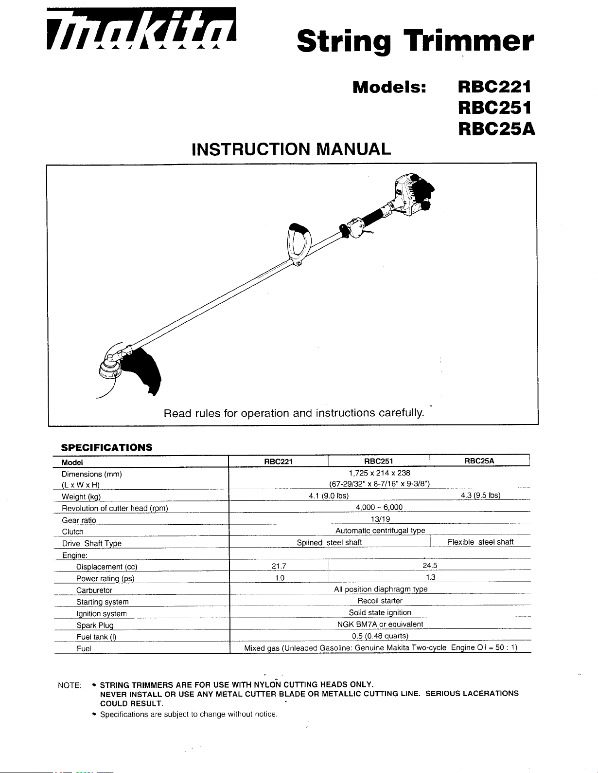
String
Trimmer
Models:
INSTRUCTION MANUAL
RBC221
RBC251
RBC25A
Read
Model RBC221 RBC251
Dimensions
(L
x W x
Weight
Revolution
Gear ratio
Clutch
Drive Shaft Type
Engine:
NOTE:
(mm)
H)
(kg)
of
cutter head
Displacement (cc)
Power rating
Carburetor
Starting system
Ignition system
Spark Plug
Fuel tank
Fuel
@s)
(I)
STRING
NEVER INSTALL
COULD RESULT.
Specifications are subject
TRIMMERS
(rpm)
OR
rules
for operation and instructions carefully.
Splined steel shaft
21.7 24.5
1
.o
Mixed gas (Unleaded Gasoline: Genuine Makita Two-cycle Engine
,.
ARE
FOR
USE
WITH
USE ANY METAL CUTTER BLADE
to
change without notice.
NYLON
CUTTING
1,725~214~238
(67-29132" x 8-711 6" x 9-318")
4.1 (9.0
Ibs)
4,000 - 6,000
1311 9
Automatic centrifugal type
All
position diaphragm type
Recoil starter
Solid state ignition
NGK
BM7A or equivalent
0.5
(0.48
HEADS
OR
ONLY.
METALLIC CUTTING LINE. SERIOUS LACERATIONS
quarts)
4.3 (9.5
Flexible steel shaft
1.3
RBC25A
Ibs)
Oil
=
50 : 1)
Page 2
Thank you very much
in recommending our MAKITA
knowledge and experience.
Please
order
STRING TRIMMERS
Always use the proper machine
read
and understand this booklet thoroughly
to
take advantage
for
purchasing your MAKITA STRING TRIMMER. We
STRING
of
its outstanding performance.
are
designed
are
proud
of
TRIMMER
for
trimming grass, weeds and low growth, non-wood ground cover.
for
the
job.
as
a
before
result
of
our extensive development and substantial
operating your MAKITA STRING TRIMMER in
and very confident
SAFETY RULES
Proper safety precautions must
DO NOT
use
to
and
1.
2.
3.
4.
5.
6.
7.
8.
9.
10.
11.
12.
13.
14.
15.
16.
17.
18.
19.
20.
21.
22.
EXPOSE
this machine unless they
are
trained in its operation.
Always wear safety goggles
that
could
worn.
from flying
Inspect
as
necessary
DO
NOT
injury
to
Keep the handles
Always use the proper handle and shoulder strap when cutting.
Do not smoke while mixing
Do
not mix fuel in an enclosed room
Always mix and store the fuel in
ordinances
Never remove the fuel tank cap while the engine
Never start
dangerous carbon monoxide.
Never attempt
make engine adjustments with the unit resting on
Do
not use the unit
Inspect the area
Also remove any objects that the unit may throw during cutting.
Keep children away. Onlookers
Never leave the machine unattended.
Do
no use this unit
Do not overreach. Keep proper footing and balance
ladder
Keep hands and feet
Do not
Do
not use the unit when you
Do
not use a damaged cutting head.
nylon cutting
for
changing
Do
not store in
furnaces,
YOURSELF
become caught in moving parts
Long hair should
debris
the
during operation.
entire machine for
before
US€
any attachment with this power head other than one recommended by MAKITA. Serious
the user
or
free
for
such usage.
or
run the engine inside a closed
to
make engine adjustments while the unit
to
or
any other unstable footing location.
use
this type
head.
accessories.
a
closed
etc.
Store
be
observed. Like
OR
OTHERS TO DANGER.
are
thoroughly responsible and have
for
eye protection. Dress appropriately; do not wear
be
tied
back.
loose
using the machine.
bystanders
of oil
or
and fuel.
fuel
if
it
is
damaged
be
cut
and remove
for
any
jobs
clear
of
the nylon cutting
of
machine
are
A
broken
in a locked, well ventilated
area
or
where
It
is
parts (nuts, bolts, screws, etc.) and any damage. Repair
damage
or
filling tank.
or
near open flames. Assure adequate ventilation.
a
properly marked container that
or
poorly adjusted. Never remove the machine's guard.
all
should
other
for
unbalanced nylon cutting
be
than
sweeping away debris.
tired
or
If
a
fuel
AND
all
power equipment
of
the unit.
recommended that legs and feet
to
the engine could result.
is
room
a
debris that could become entangled in the nylon cutting
kept at
those
for
head
under the influence
stone
or
any other
vapors can
area
PRECAUTIONS
this
unit must
Follow these general rules.
read
and understood the machine manual
Safe,
sturdy, nonskid footwear should always
is
approved by
running.
or
building. Fumes from the exhaust contain
is
running and strapped
flat,
clear
surface.
a
safe
distance from the work
which
it
is
intended
at
all
times.
while
the
unit
of
medication, drugs
obstacle
head
must never
reach
an open flame from
only.
as
Do
not run the unit while standing on
is
in
use.
is
hit, stop the engine and
be
handled carefully.
Do
not permit others
loose
clothing
be
covered to protect them
local
codes
to
the operator. Always
area,
at least
described in the manual.
or
alcohol.
be
used.
hot
Follow instructions
water heaters,
or
or
replace
and
50
check
jewelry
be
head.
feet.
a
the
-
.
2
Page 3
23.
Use
only
replacement parts that are identical to original equipment parts when servicing the
from
parts are available
potential hazard,
24.
Clean the machine completely, especially
When refueling, be sure
25.
engine
is
running
injury
your dealer. The use
to
the
user and damage
to
stop the engine and confirm that
or hot. When gasoline
of
any other accessory or attachment may create a
to
the machine.
the
fuel tank cap,
spills,
be sure to completely wipe
its
surroundings, and
it
has cooled down. Never refuel when the
the
air cleaner.
it
away and properly dispose
those materials before starting the engine.
Stay clear of other workers or
26.
When approaching an operator of the machine, carefully call
27.
bystanders.
his
attention and confirm that the operator
stops the engine. Be careful not to startle or distract the operator causing an unsafe situation.
Never touch the nylon cutting head while the engine
28.
nylon cutting head, be sure
to
stop
the
engine and confirm that the nylon cutting head has stopped
is
running.
If
it
is
necessary
to
adjust the protector or
turning.
The
29.
30.
31.
engine should be turned off when the machine
Be careful not to
will
shorten the life
hit
the
nylon cutting head against stones, or the ground. Unreasonably rough operation
of
the machine as well as create an unsafe environment for you and those around you.
Pay attention to loosening and overheating of parts.
operation immediately and check the machine carefully.
qualified service facility. Never continue
In
32.
startup or
wire or the spark
For a while after the engine has stopped, the muffler
33.
materials
Pay special attention when operating
34.
If
35.
36.
37.
you
Be careful not to drop the machine or
Before proceeding to adjust
cap from the
Before storing the machine for a long time, drain all fuel from the fuel tank and carburetor, clean the
38.
slip
during
(dry
or fall
operation of the engine, never touch hot parts such as the muffler, the high-voltage
plug.
grass, etc.), combustible gasses or combustible
to
the
ground or into a hole, release the throttle lever immediately.
or
repair the machine, be sure
spark
plug.
to
operate a machine which may be malfunctioning.
in
the
rain
hit
it
against obstacles.
is
moved between work areas.
If
there
is
any abnormality
If
necessary, have the machine serviced
is
still
hot. Never place
liquids.
or
shortly after the rain as the ground may
to
stop
the
engine
of
the machine, stop
the
machine near flammable
and
detach the
parts, move the machine to a safe place, and confirm that the engine has cooled down.
Make periodic inspections to assure safe and efficient operation,
39.
your machine, please contact your nearest Makita Factory Service Center
Keep the machine well away from fire or sparks.
40.
Warning: The cutter area
41.
Don't try to tackle a
42.
big
is
dangerous while the machine
job
with
an undersized machine. Use
is
If
you need professional inspection
or
authorized dealer.
coasting to a stop.
this
machine only for
trimming;
mower for large areas.
Wear a
43.
44.
Wear hearing protection for extended periods
Keep
45.
Never operate
46.
dust
guards
mask
in
dusty
and protectors
this
machine while
work conditions.
in
place and
it
in
is
turned upside-down or when
of
use, and any time the noise
working order.
is
uncomfortable.
it
is
at an extreme angle.
unit:
these
be
slippery.
spark
use a lawn
by
plug
of
a
of
CAUTION! CAUTION! CAUTION!
WHEN MIXING GASOLINE WITH TWO-CYCLE ENGINE OIL, USE ONLY GASOLINE WHICH CONTAINS NO
OR
ETHANOL
ENGINE FUEL LINES AND OTHER ENGINE PARTS.
METHANOL (TYPES
OF
ALCOHOL), THIS
SAVE THESE INSTRUCTIONS.
WILL
HELP TO AVOID POSSIBLE DAMAGE
TO
3
Page 4
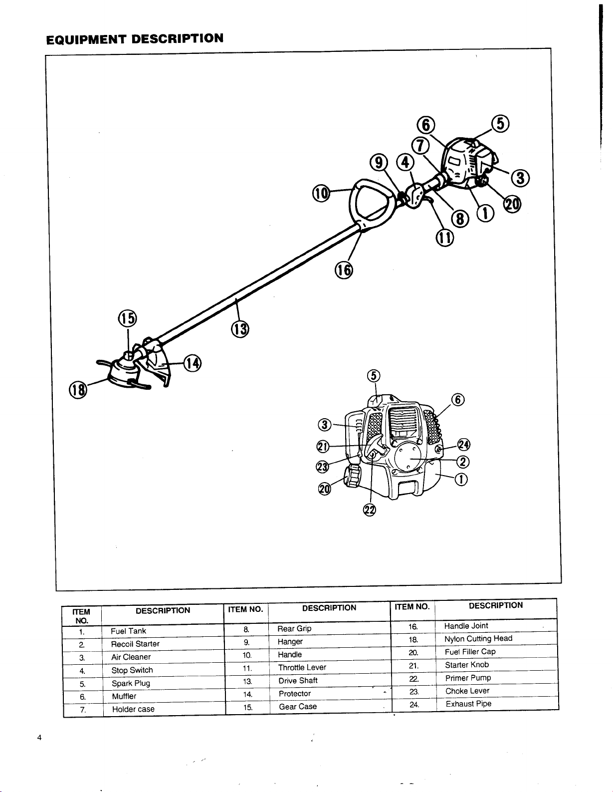
EQUIPMENT DESCRIPTION
4
Page 5
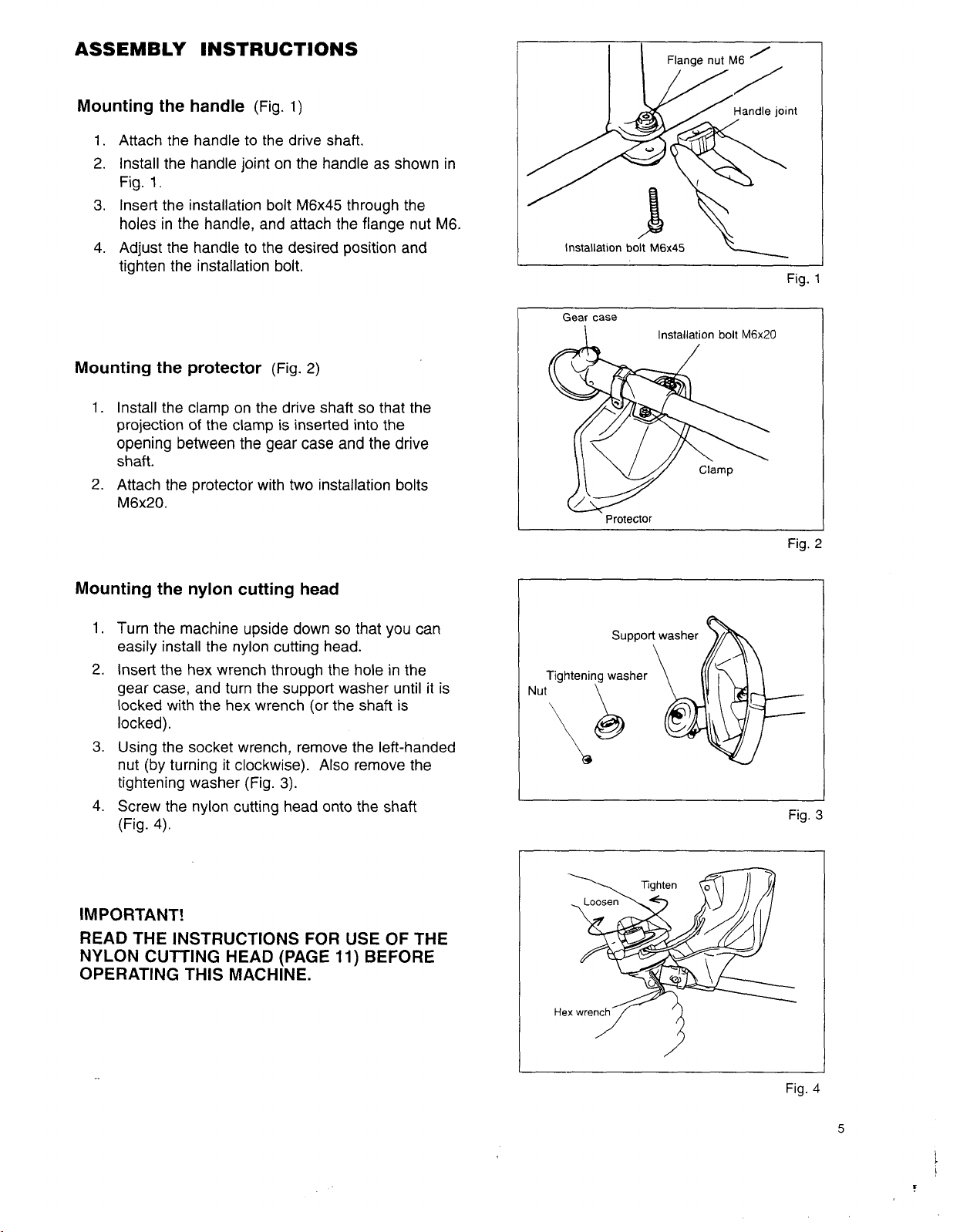
ASSEMBLY
INSTRUCTIONS
Mounting the handle
1.
Attach the handle
2.
Install the handle joint
Fig.
1.
3.
Insert the installation bolt M6x45 through the
holes
in
the handle,
4.
Adjust the handle to the
(Fig.
1)
to
the drive
on
and
shaft.
the handle
attach the flange nut
desired
as
position and
tighten the installation bolt.
Mounting the protector
1.
Install the clamp on the drive shaft
projection
opening between the
of
the clamp
(Fig.
2)
is
inserted into the
gear
case
and
so
that the
the
shaft.
2. Attach the protector with two installation bolts
M6x20.
shown
M6.
drive
in
I
I
Installation bolt
Gear case
I
Protector
M6x45
Installation bolt
\
M6x20
Fig.
Fig.
1
2
Mounting the nylon cutting head
1.
Turn the machine upside down
so
that
easily install the nylon cutting head.
2.
Insert the hex wrench through the hole in the
gear
case,
and turn the support washer until it
locked
with the hex wrench
(or
the
shaft
locked).
3.
Using the socket wrench, remove the left-handed
nut (by turning it clockwise).
tightening washer (Fig.
4.
Screw the nylon cutting head onto the shaft
(Fig.
4).
3).
Also
remove the
IMPORTANT!
READ THE INSTRUCTIONS FOR
NYLON CUTTING HEAD (PAGE
USE
11)
BEFORE
OPERATING THIS MACHINE.
you
is
OF
can
is
THE
Tightening
Nut
Hex
washer
wrench
77
Fig.
3
Fig.
4
5
f
Page 6

PREPARING FOR OPERATION
Fuel and
Inspect the fuel tank and
oil
mixture
fill
with clean, fresh fuel
of
the proper mixture to assure the longer
life
of
the tool.
Use
the following mixed gas.
Gasoline : Genuine Makita Two-cycle engine
Gasoline : Other manufacturer's Two-cycle engine
FOR CALIFORNIA REGULATION:
THIS
EQUIPMENT
IS
CERTIFIED TO OPERATE ON GASOLINE + TWO-CYCLE ENGINE OIL
oil
=
oil
50
:
=
1
or
25
:
1
recommended
WHEN MIXING GASOLINE WITH TWO-CYCLE ENGINE OIL, USE ONLY GASOLINE WHICH CONTAINS NO
ETHANOL
OR
METHANOL (TYPES
OF
ALCOHOL). THIS WILL HELP TO AVOID POSSIBLE DAMAGE
TO
ENGINE FUEL LINES AND OTHER ENGINE PARTS.
DO NOT MIX GASOLINE AND
IMPORTANT:
CAUTION:
1.
When preparing fuel mixture, mix only the amount needed
Failure
to
mixture that has been stored longer than
starting and poor performance.
and replaced with
2.
Never
fill
the
3.
Never
add
4.
Do not
5.
Be sure to wipe
6.
Do not attempt
add
fuel to
a
fuel
tank
the
fuel to this unit
off
to
refuel a hot engine.
OIL
follow
proper
fresh
mixture.
to
the very top.
tank in
a
close
spilled fuel
DIRECTLY
fuel
IN
mix instructions may cause damage
two
If
fuel mix has been
closed,
unventilated
to an open
before
attempting to start the engine.
THE FUEL TANK.
to
the
engine.
for
the
job
you
are
to
do.
Do not use fuel
months. Fuel mixture stored longer than this will cause hard
stored
longer than this time, it should
be
removed
area.
fire
or
sparks.
Check points before operation
1.
Check
Check
2.
3.
Check
6
for
the
to
be
loose
bolts, nuts and fittings.
air
cleaner
sure
that protector
for
,'
dirt.
Clean the
is
air
filter
securely in place.
of
all
dirt,
etc. before operation.
Page 7

ENGINE STARTING AND STOPPING
PROCEDURES
Stop
Position
'"0
Start
7"
Position
Starting when the engine
Use
the following procedure when the engine
has
been stopped
for
is
cold
longer than 5 minutes,
is
or
cold,
after
or
fuel
after it
has
been added to the engine:
1.
Slide the stop switch away from the "STOP" position
5).
(Fig.
2.
Gently push on the primer pump repeatedly
fuel
until
3.
Close the choke lever fully by moving it to the
[XI
4.
Lock
enters the primer pump (Fig.
position (Fig.
6).
the throttle lever in the "start" position
6).
(7
-
as
follows:
10
times)
i). Squeeze the throttle lever fully.
ii).
Hook
the lock fin to the notch in the throttle lever
case
while releasing the throttle lever (Fig.
Place
5.
the machine on the ground. Hold the drive shaft
or
the grip with one hand, and give several strong pulls
7).
the starter using the other hand.
6.
After the engine has started, open the choke lever fully
to
the
I$I
by moving it gradually
7.
Release the throttle lever
Note:
The throttle lever
is
position.
fully.
unlocked by squeezing it
slightly.
Restarting immediately after the engine has stopped.
to
I
Choke
lever
Fig.
Fig.
5
I
6
1.
Slide the stop switch away from the "STOP" position
5).
(Fig.
2.
Gently push on the primer pump repeatedly
until fuel enters the primer pump (Fig.
3.
Leave the choke lever in the open
4.
Leave the throttle lever fully
5.
Place
the machine on the ground. Hold the drive
shaft
or
grip with one hand, and give several strong
pulls
to
the starter using the other hand.
1$1
released.
(7 - 10
6).
position (Fig.
times)
6).
CAUTION:
Never operate the engine at high rpm without load. With
the throttle lever fully squeezed and no load, the engine
rpm will be very high which could have an adverse effect
on the
life
of
the engine.
Stopping
1.
Release the throttle lever fully.
2.
When the engine rpm has lowered, push the stop
switch to the "STOP" position. The engine will stop.
Idle adjustment
The nylon cutting head should not run when the throttle lever
fully released.
adjusting screw (Fig.
If
necessary,
8).
adjust
the
idle
rpm using the idle
Fig.
7
is
Idle
adjusting
screw
Fig.
8
7
F
Page 8

CORRECT HANDLING
OF
THE MACHINE
Fig.
9
.
Fig.
10
Attachment, adjustment and detachment
Attachment
Place
the strap
Adjustment
Adjust the strap length
Detachment
hook
into the hanger which
so
(NORMAL)
that the nylon cutting
is
located
of
head
Remove the strap hook from the hanger
Detachment
In an emergency,
10).
(Fig.
deflected toward you
(EMERGENCY)
release
the throttle lever, firmly pull the
Be extremely cautious
or
anyone in the work vicinity.
to
maintain control
Notes:
The shoulder strap has a quick
is
Check that the hook
11.
If
it
is
Fig.
as
shown. (Fig.
not, remove it and reassemble it
11)
assembled
release
as
shown in
the shoulder strap
on the
will
of
system.
shaft
between the grip and the handle.
be
kept parallel to the ground (Fig.
release
belt upward and detach the machine from you
the machine at this time.
I I
Hook
\
9).
Do
not allow the machine
Release
Belt
\
to
be
strap
8
Page 9

DAILY CHECK-UP AND MAINTENANCE
cover
Fig.
12
I
Sponge element
r
cleaner case
cleaner
cover
Fig.
13
0.6
mm
-
0.7
(0.024" - 0.028")
1.
Before operation, pay particular attention
cutting head
2.
Check for clogged cooling air passage and cylinder
3.
Clean the air cleaner every
i).
mm
Fig.
14
if
necessary (every 8 hours or daily).
8
hours or daily,
Remove the air cleaner cover. Clean the sponge element and remove any excessive
adhering to the cleaner
(Fig.
12 and
start the engine or to increase the engine rotational speed
Re-install the sponge element around the
ii).
4.
Check the spark
The gap between the two electrodes
If
the gap
If
the spark
5.
Apply
grease (SHELL
hours
(Fig.
6.
FOR
RBC25A
Apply
grease (SHELL
i).
Pull
the gear case from the drive shaft after removing bolts.
Pull
ii).
7.
Clean the muffler exhaust port every
Check the fuel filter.
a.
Replace the fuel lines every
9.
10.
Overhaul the engine every 200 hours or yearly.
11.
Replace the packing and gaskets
the flexible shaft out of the drive shaft housing.
plug
every 8 hours
is
too
wide or too narrow, adjust
plug
is
clogged
with
ALVANIA
15).
ONLY
ALVANIA
If
clogged, replace
200
or
daily.
of
the
carbon or fouled, clean
No. 3 or equivalent)
No.
2
or equivalent)
50
hours or yearly.
with
new ones every time the engine
to
the tightness of
using
13).
A
clogged air cleaner may make
ribs
spark
plug
it.
hours
or
monthly.
it
with
a new one every
the
nylon cutting head. Re-tighten
fins.
Clean them
if
necessary (every 8 hours or daily).
the following procedure:
it
difficult
of
the air cleaner case.
should be
it
thoroughly or replace
to
the gear case through the grease hole every
to
the flexible shaft every
Apply
0.6
to
0.7
mm
(0.024"
it
(Fig.
50
hours.
grease to the drive shaft.
50
hours or monthly.
is
reassembled.
to
14).
Fig.
dust
or
impossible
0.028").
I
15
the
or
dirt
nylon
to
30
9
Page 10

STORAGE
When storing
1.
Drain
the primer pump. Properly dispose
2.
Remove the spark plug and
assure
3.
Clear
oil-immersed cloth and store the machine in
REASSEMBLY
the
machine
all
fuel from the
that
an
oil
or
blow any
INSTRUCTIONS
for
a
long time, drain
fuel
tank. Gently push on the primer pump repeatedly until
add
a
few drops
the
fuel from the fuel tank and carburetor
of
the fuel in accordance with
of oil
film coats the engine inside, then insert and tighten the spark plug.
dirt
or
dust from the nylon cutting
a
dry
Reassembling the drive shaft and the engine.
The
shaft
and the engine on this machine have been
If
assembled in the factory.
(example,
for
maintenance) carefully reassemble it
you remove the shaft
as
shown below:
1.
Loosen
shaft into the holder
the
screws M5x18 and insert the drive
case
(Fig. 16).
Note:
i).
Always insert
case
fully (approx.
shaft
resists
try
to
insert
support washer on the gear
ii).
Be cautious not
be pinched between the holder
grip end.
2.
After making sure that the drive
fully and properly, tighten the screws M5x18
secure the drive shaft.
3.
Insert the nipple
square
hole
square hole in the moving part which
grip. The nipple should move when the throttle
lever
is
squeezed (Fig.
Note: Squeeze the throttle lever to make sure that
the throttle wire moves smoothly.
4.
Connect the two switch wires
by inserting one into the other.
5.
Cover the throttle wire and switch wires with split
tubing.
Note:
It
is
easier
connectors
cover
to
remove
the
drive shaft into the holder
60";
full
insertion
it
again while slightly rotating the
2-3/8").
of
the
If
the
drive shaft,
case.
to
allow the switch
shaft
of
the throttle wire through the
cords
case
is
and the
installed
in the grip until it fits into an inner
is
inside the
17).
to
the engine wires
to
install
the
split tubing
are
partially pushed into the motor
slack
from
the
if
the bullet
wires (Fig.
18).
inner
to
to
all
into the spark plug
head
and engine housing; wipe them with an
location.
0
Nipple
local
hole.
Screw
as
foll,ows:
all
fuel
is
expelled
laws.
Then, pull the starter gently
M5x18
Holder
case
of
throttle wire
Fig.
Fig.
out
16
17
of
to
10
-
Fig.
1E
Page 11

INSTRUCTIONS FOR
(BUMP
&
FEED BF4)
USE
Safety Instructions
1.
Read
this
section carefully and thoroughly before use.
2.
Check the nylon
If
you notice any of following, replace the worn
damaged parts
Dents appear on the knob head.
The housing (cover)
The
"Limit
disappeared.
3.
Wear appropriate clothing and protectors.
4.
Always stop
head
BF4
5.
Do
not
allow anyone near
cutters
harming bystanders.
6.
Never
head speed higher than
might
use
cutting
with
marks (notches)" on the cover have
the
engine before inspecting the cutting
or replacing the nylon cord.
send stones or debris
the
cutting head
head carefully before each
new
ones immediately
is
damaged or cracked.
the
10,000
OF
THE
(Fig.
operation area. The
flying,
possibly
BF4
on
tools
with
RPM.
NYLON CUTTING
use.
or
19):
a cutter
$i
HEAD
imit
mark
(notch)
Fig.
19
Installation
See page 5 (Mounting the nylon cutting head)
Operation
1.
Increase the cutter head speed to approx.
RPM.
inefficient cutting. Use the
(shaded area shown
cutting.
2.
When the nylon cord wears down (becomes short),
decrease the engine speed to
and
against the ground to feed
I
I
Low speed (under 4,000
in
Fig.
bump
the
Parts
knob of
Breakdown
the
RPM)
tip
of
the nylon cord
20)
for more effective
under
4,000
nylon cutting head
out
the nylon cord
6,000
causes
RPM
(Fig.
I
Fia.
211.
-
22
Shaded area
I
I
Fig.
Fig.
20
21
Page 12

Replacing the nylon cord
1.
Press
the
housing latches
then
2.
Run
the
of
the
end
than
3.
Wind
direction of
4.
Wind
cord, leaving
notch on
Mount
5.
and
the
6.
Unhook
position
the
7.
Align
with
firmly
remove
the
spool,
notch into
of
the
both
all
protrusions on
housing.
side
the
the
onto
the
new
nylon cord through
and
the
the
cord to
other
end
ends
firmly
the
head
but
about
the
the
side
the
spool
in
the
ends
and
feed
of
the
housing (Fig. 27).
protrusions on
slots
of
the
the
housing to secure
spool (Fig. 23).
pass
one
other side of
extend
(Fig. 24).
around
rotation (Fig.
4"
(100
ends
temporarily hooked through a
of
the
the
housing
the
spool
of
the
the
cords out through
eyelets.
inward
about
mm)
spool (Fig. 26).
cord from
the
to
the
end
of
the
the
spool. Allow one
3"
(80
the
spool
25).
to
6
so
that
are aligned
their
underside
Then
push
it
(Fig. 28).
lift
hole
(150
off
the
cover;
in
the
center
cord through
mm)
further
in
the
mm)
of
the
grooves
with
those
temporary
the
eyelets
of
the
cover
the
cover
the
in
in
I
I
3"
,
Fig.
(80
mm)
Notch
I
iiR
Holes
1
23
I
Models
RBC221 I RBC251 I RBC25A
wind
cord
in
Fig.
25
I
4"
to
(100
6"
mm)
(150
Fig.
mm)
Fig.
24
26
12
Eyele
\\
Fig.
27
Protri
I
I
Fig.
I
28
Page 13

Emission Control Warranty Statement
YOUR WARRANTY RIGHTS AND OBLIGATIONS
The
California Air Resources Board and Makita
on your
1995
and later utility and/or lawn and garden equipment engine. In California, new utility and lawn and
garden equipment engines must be designed, built and equipped to meet
dards. Makita
ment engine for
U.S.A.,
the
periods
Inc. must warrant
of
time listed below provided
the
maintenance of your utility andlor lawn and garden equipment engine.
U.S.A.,
Inc.
are
pleased
emission control system on your utility and/or lawn and garden equip-
there
has
been
to
explain
the
no
the
emission control warranty
State's stringent anti-smog stan-
abuse, neglect
or
improper
Your emission control system includes parts such as
and
the
catalytic converter. Also included are the hoses and connectors and other emission-related assemblies.
Where a warrantable condition exists,
ment at no cost
to
you including diagnosis,
Makita
parts
U.S.A., lnc.
the
carburetor or fuel injection systems,
will
and labor.
the
ignition system
repair your utility and/or lawn and garden equip-
MANUFACTURER'S WARRANTY COVERAGE:
The
1995
and later utility and/or lawn and garden equipment engines are warranted for two years.
sion-related part on your engine
is
defective,
the
part
will
be
repaired or replaced by Makita U.S.A., Inc.
If
any emis-
OWNER'S WARRANTY RESPONSIBILITIES:
As
the
utility and lawn and garden equipment engine owner, you
required maintenance listed in your owner's manual. Makita
covering maintenance on your utility and/or lawn and garden equipment engine, but Makita U.S.A., Inc. cannot
deny warranty solely for the lack of receipts or for your failure to ensure
tenance.
As
the
utility and/or lawn and garden equipment engine owner,
U.S.A., Inc. may deny you warranty coverage
if
your utility and/or lawn and garden equipment engine or a part
has failed due to abuse, neglect, improper maintenance or unapproved modifications.
are
responsible for the performance of
U.
S.A., Inc. recommends that you retain
the
performance of all scheduled main-
you
should be aware, however,
that
the
all
receipts
Makita
You
are
responsible for presenting your utility and/or
service center as
exceed
If
30
you have any questions regarding your
days.
a
problem exists. The warranty repairs should be completed in a reasonable time, not to
warranty
lawn
rights
and
garden equipment engine to
and
responsibilities, you should contact
a
Makita
U.S.A., Inc.
a
Makita
Factory Service Center Manager nearest you. A list of the Factory Service Center locations and phone numbers
is provided below for your convenience.
13
Page 14

LIMITED WARRANTY
-
California Only
-
Makita
1995 and later
and equipped at the time of manufacture
Resources Board, and
form
U.S.A.,
with
Inc., a distributor of
utility
and/or lawn and ga'rden equipment engines
(2)
is
those regulations as applicable according to the terms and conditions stated below.
utility
and lawn and garden equipment
so
as
free from defects
in
the
that
the engine
to
conform
in
materials and workmanship which
with
the
applicable regulations of the California
U.S.,
(1)
has
may
WARRANTY PERIOD
The warranty period begins on the date which the
to
the original retail purchaser and ends
Inc. warrants
in
material and workmanship that can cause the failure of a warranted emission-related part.
to
the original retail purchaser and each
WHAT
Repair and/or replacement of any warranted emission-related part
work
is
performed at an authorized warranty station. There
formed at an authorized warranty station which leads
is
defective.
Any
warranted
for regular inspection
Any
warranted part which
od of time
replacement, and/or adjustment of
up
to
part
the
which
is
not scheduled for replacement as required maintenance, or which
to
the effect of "repair or replace as necessary"
is
scheduled for replacement as required maintenance shall
first
scheduled replacement of that
two
IS
COVERED UNDER THIS WARRANTY
the
component parts listed below.
utility
and/or lawn and garden equipment engine
years after that date.
subsequent
will
also
to
the determination that a warranted emission-related part
part.
This
During
purchaser that the engine
will
warranty
this
two
year period Makita
be
performed at no charge provided
be
no charge for any diagnostic labor
shall
be warranted for the warranty period.
shall
apply only towards
warrants to the owner of
been designed,
cause
it
to
is
free from defect
is
scheduled only
be
warranted for the
fail
to
is
delivered
U.S.A.,
the
built,
Air
con-
the
per-
repair,
peri-
EMISSION-RELATED PARTS COVERED UNDER THIS WARRANTY
1.
Fuel Metering Systems
(a) Carburetor and
(b)
Air
cleaner plate
(c)
Air
cleaner case
(d)
Air
cleaner element
(e) Fuel filter
2.
Ignition
(a) Spark
(b)
(c) Ignition Coil
3.
Other Miscellaneous Items Used
(a) Fuel Hoses
(b)
If
it
is
determined
the failure
replace the necessary componerlts.
Systems
Plug
Flywheel Magneto
Sealing Gaskets
by
of
a warranted emission-related part
its
internal parts
an authorized warranty station that other engine components have been damaged due
in
Above Systems
during
the warranty period, Makita
U.S.A.,
Inc.
will
repair and/or
-
to
14
Page 15

WHAT
This
warranty does not cover any emission-related part which malfunctions, fails, or
ations and/or modifications such as changing, adding,
When an engine
tors, or warranty stations shall not be liable
of
time or inconvenience.
This
limited warranty also does not apply to any emission-related
due to failure
is
being serviced under warranty, Makita U.S.A., Inc. and any
to
follow the maintenance and operating instructions specified
IS
NOT COVERED UNDER THIS WARRANTY
or
removing parts.
for
any
loss
of use of the engine, for any damage to
part
which malfunctions,
Manual including:
(a) Improper
(b)
Improper installation, adjustment, or repair
performed
(c) Failure
(d)
Repairs and diagnosis performed outside
(e) Use of parts which are not authorized
or
inadequate maintenance of any warranted emission-related part.
of
by
a factory authorized warranty station.
to
use recommended fuel as specified
by
the engine
in
the
of
an authorized warranty station.
Makita U.S.A., Inc.
or
any warranted emission-related part unless
1995
and later Owner's Manual.
MAINTENANCE SCHEDULE
is
damaged due to alter-
of
its
authorized dealers,
goods,
fails,
or
is
in
the 1995 and later Owner's
distribu-
or
loss
damaged
The engine owner
intervals specified
performed.
These
is
responsible for having all scheduled inspection and maintenance services performed at the
in
the 1995 and later Owner's Manual and
records should be transferred to each subsequent owner
to
retain records of these services as having been
of
the
engine. Makita
U.S.A.,
Inc.
cannot deny a claim solely because there are no records of scheduled maintenance; however, a warranty claim
by
may
denied
the failure
related part.
described below which are based on the procedures described
PROCEDURE
Check all
Check air passages and engine cylinder
if
the failure
to
perform the scheduled maintenance and inspection resulted
As
a
minimum,
nuts
to
perform the scheduled maintenance; however, a warranty claim may
the engine owner
is
responsible for the scheduled inspection and maintenance
and bolts and tighten as necessary.
fins
for clogging
in
the Owner's Manual.
by
in
the failure
of
a warranted emission-
INTERVAL
Every 8 hours of use or daily.
Every
8
hours of use or daily.
denied
Remove all obstructions as necessary.
Clean the air cleaner.
Check the spark
plug.
Clean and adjust
Check the muffler exhaust port. Clean
Check the fuel filter.
If
clogged, replace
Replace fuel lines.
Overhaul the engine.
Replace the packings and gaskets.
it
if
necessary.
it
if
necessary.
it
with
a new filter.
Every 8 hours of use
Every
8
hours of use
Every
50
hours of use
Every
50
hours of use or
Every
200
hours
Every
200
hours of use
Every time the engine
or
daily.
or
daily.
or
monthly.
monthly.
of
use or yearly.
or
is
reassembled.
yearly.
if
15
Page 16

REPAIR AND REPLACEMENT
It
is
recommended that only engine replacement parts which have
U.S.A.,
parts. These replacement parts
Inc. should
be
used
in
the performance of any warranty maintenance or
will
be provided at no charge
OF
EMISSION-RELATED PARTS
been
authorized and approved
if
the part
repairs
is
still
under
of
emission-related
warranty.
by
Makita
i
HOW
TO
FILE A WARRANTY CLAIM
AND WHERE TO GET WARRANTY SERVICES
Contact the nearest Makita Factory Service Center Manager
required warranty services are
bers are provided below for your convenience.
14930
La Mirada,
(71 4) 522-8088
1421
Fresno,
(209) 252-51 66
392
Northam
CA
90638-5753
N.
Clovis Ave., Ste.
CA
93727
S.
Arrowhead Ave., #A-1
San Bernardino,
(909) 885-1 289
1714
E.
McFadden Ave.,
Santa Ana,
(71 4) 667-5066
16735
Van
Nuys,
(81 8) 782-2440
CA
Saticoy
CA
92705
St.,
91406
Street
CA
Ste.
to
92408
105
be
performed.
112
Unit
M
A
list
of the Factory Service
to
determine the appropriate location where
Center
41 850
Fremont,
(51
4554
Christy
0)
657-9881
Roseville
CA
94538-51 07
North Highlands,
(91 6) 331 -621 1
7674
Clairemont
San
Diego,
(61 9) 278-4471
333
Littlefield Ave.
S.
San Francisco,
5)
(41
CA
875-1 002
locations and phone
Street
Rd.,
Ste.
E
CA
95660
Mesa
Blvd.
921
11
CA
94080
the
num-
16
A
MCA
5/96
WARN I NG
to the State
-
of
California to cause cancer, birth defects
:
The Engine Exhaust from this product contains chemicals known
or
other reproductive harm.
Makita Corporation
2650
Buford
Buford, Georgia
884031 8992
of
America
Hwy
3051 8
PRINTED
IN
USA
1996-5-4D
 Loading...