

GB
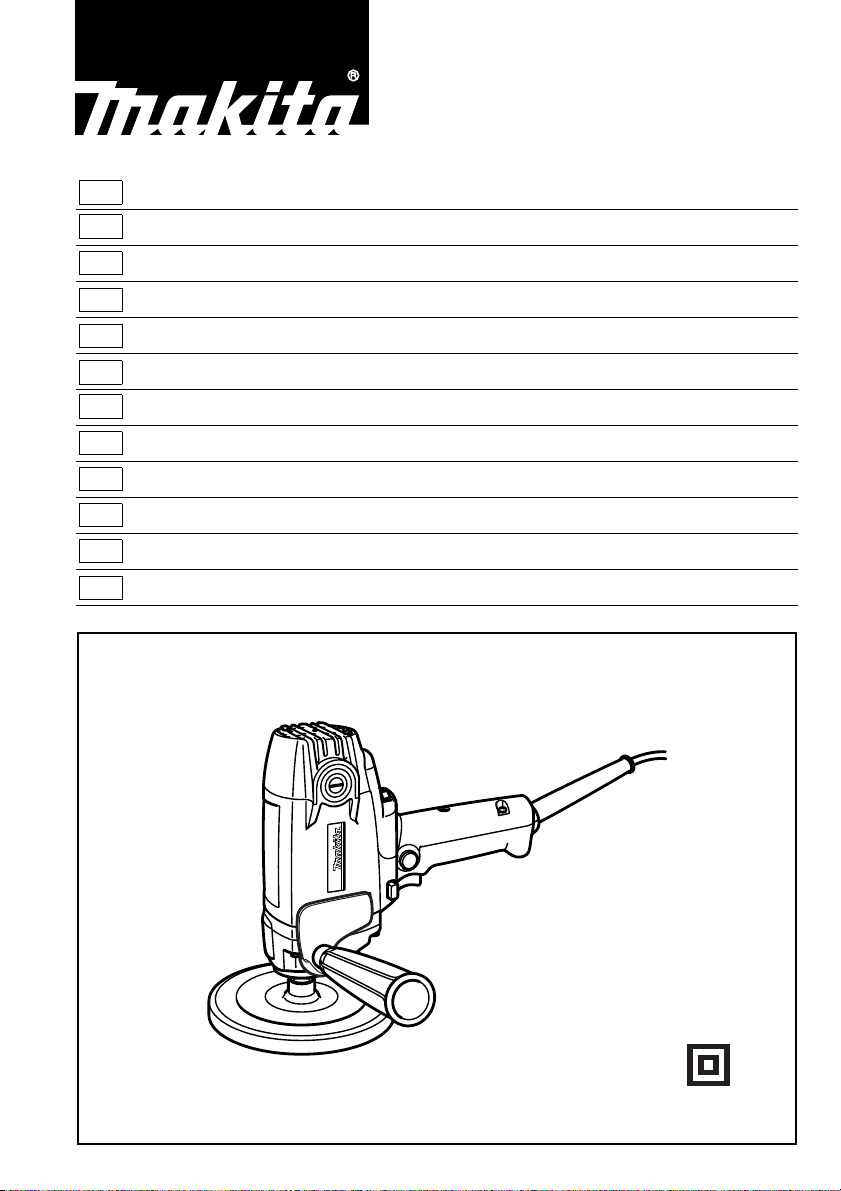
Electronic Polisher Instruction Manual
F
Polisseuse électronique Manuel d’instructions
D
Elektronik-polierer Betriebsanleitung
I
Lucidatrice elettronica Istruzioni per l’uso
NL
Elektronische polijstmachine Gebruiksaanwijzing
E
Pulidora Manual de instrucciones
P
Polidora electrónica Manual de instruções
DK
Elektronisk poleremaskine Brugsanvisning
S
Elektronisk poleringsmaskin Bruksanvisning
N
Elektronisk polermaskin Bruksanvisning
SF
Elektroninen hiomakone Käyttöohje
GR
Ηλεκτρονικς στιλβωτήε Οδηγίες χρήσεως
PV7000C
1
1
2
2
18
3
4
123
2
5
45
6
9
7
8
6
67
10
11
12
13
8
89
2
10 11
15°
12 13
13
15°
11
14
12
7
15°
8
14 15
15
16 17
16
17
3

Symbols
The following show the symbols used for the tool. Be sure that you understand their meaning before use.
Symboles
Nous donnons ci-dessous les symboles utilisés pour l’outil. Assurez-vous que vous en avez bien compris la signification avant d’utiliser l’outil.
Symbole
Die folgenden Symbole werden für die Maschine verwendet. Machen Sie sich vor der Benutzung unbedingt mit ihrer
Bedeutung vertraut.
Symboli
Per questo utensile vengono usati i simboli seguenti. Bisogna capire il loro significato prima di usare l’utensile.
Symbolen
Voor dit gereedschap worden de volgende symbolen gebruikt. Zorg ervoor dat u de betekenis van deze symbolen
begrijpt alvorens het gereedschap te gebruiken.
Símbolos
A continuación se muestran los símbolos utilizados con esta herramienta. Asegúrese de que entiende su significado
antes de usarla.
Símbolos
O seguinte mostra os símbolos utilizados para a ferramenta. Certifique-se de que compreende o seu significado antes
da utilização.
Symboler
Nedenstående symboler er anvendt i forbindelse med denne maskine. Vær sikker på, at De har forstået symbolernes
betydning, før maskinen anvendes.
Symboler
Det följande visar de symboler som används för den här maskinen. Se noga till att du förstår deras innebörd innan
maskinen används.
Symbolene
Følgende viser de symblene som brukes for maskinen. Det er viktig å forstå betydningen av disse før maskinen tas i
bruk.
Symbolit
Alla on esitetty koneessa käytetyt symbolit. Opettele näiden merkitys, ennen kuin käytät konetta.
Σύµβολα
Τα ακλουθα δείχνουν τα σύµβολα που χρησιµοποιούνται για το µηχάνηµα. Βεβαιωθείτε τι καταλαβαίνετε
τη σηµασία τους πριν απ τη χρήση.
❏ Read instruction manual.
❏ Lire le mode d’emploi.
❏ Bitte Betriebsanleitung lesen.
❏ Leggete il manuale di istruzioni.
❏ Lees de gebruiksaanwijzing.
❏ Lea el manual de instrucciones.
❏ DOUBLE INSULATION
❏ DOUBLE ISOLATION
❏ DOPPELT SCHUTZISOLIERT
❏ DOPPIO ISOLAMENTO
❏ DUBBELE ISOLATIE
❏ DOBLE AISLAMIENTO
❏ Wear safety glasses.
❏ Porter des lunettes de protection.
❏ Schutzbrille tragen.
❏ Indossare occhiali di protezione.
❏ Draag een veiligheidsbril.
❏ Póngase gafas de seguridad.
❏ Leia o manual de instruções.
❏ Læs brugsanvisningen.
❏ Läs bruksanvisningen.
❏ Les bruksanvisingen.
❏ Katso käyttöohjeita.
❏ ∆ιαβάστε τις οδηγίες χρήσης
❏ DUPLO ISOLAMENTO
❏ DOBBELT ISOLATION
❏ DUBBEL ISOLERING
❏ DOBBEL ISOLERING
❏ KAKSINKERTAINEN ERISTYS
❏ ∆ΙΠΛΗ ΜΟΝΩΣΗ
❏ Utilize óculos de segurança.
❏ Bær sikkerhedsbriller.
❏ Bär skyddsglasögon.
❏ Bruk vernebriller
❏ Käytä suojalaseja
❏ Φορέστε γυαλιά ασφαλείας.
4

ENGLISH
1Cover
2 Side grip
3 Switch trigger
4 Lock button
5 Speed adjusting dial
6Pad
Explanation of general view
7 Spindle
8Wrench
9 Sponge pad
10 Wool bonnet
11 Lock nut
12 Rubber pad
13 Lock nut wrench
14 Abrasive disc
15 Limit mark
16 Brush holder cap
17 Screwdriver
18 High-low speed setting button
SPECIFICATIONS
Model PV7000C
Max. capacities
Sponge pad / Wool bonnet .............................. 180 mm
Abrasive disc ................................................... 180 mm
No load speed (min
Overall length ..................................................... 210 mm
Net weight .............................................................. 2.0 kg
• Due to our continuing program of research and devel-
opment, the specifications herein are subject to change
without notice.
• Note: Specifications may differ from country to country.
Power supply
The tool should be connected only to a power supply of
the same voltage as indicated on the nameplate, and can
only be operated on single-phase AC supply. They are
double-insulated in accordance with European Standard
and can, therefore, also be used from sockets without
earth wire.
Safety hints
For your own safety, please refer to the enclosed safety
instructions.
–1
) ...................................600 – 2,000
ADDITIONAL SAFETY RULES
1. Always use eye and ear protection. Other per-
sonal protective equipment such as dust mask,
gloves, helmet and apron should be worn when
necessary. If in doubt, wear the protective equipment.
2. Always be sure that the tool is switched off and
unplugged before carrying out any work on the
tool.
3. Accessories must be rated for at least the speed
recommended on the tool warning label. Wheels
and other accessories running over rated speed
can fly apart and cause injury.
4. Check the backing pad carefully for cracks, dam-
age or deformity before operation. Replace
cracked, damaged or deformed pad immediately.
5. Check that the workpiece is properly supported.
6. Hold the tool firmly.
7. Keep hands away from rotating parts.
8. Make sure abrasive disc or wool bonnet is not
contacting the workpiece before the switch is
turned on.
9. When sanding metal surfaces, watch out for fly-
ing sparks. Hold the tool so that sparks fly away
from you and other persons or flammable materials.
ENB047-3
10. Do not leave the tool running. Operate the tool
only when hand-held.
11. Pay attention that the wheel continues to rotate
after the tool is switched off.
12. Do not touch the workpiece immediately after
operation; it may be extremely hot and could
burn your skin.
13. If working place is extremely hot and humid, or
badly polluted by conductive dust, use a shortcircuit breaker (30 mA) to assure operator safety.
14. Do not use the tool on any materials containing
asbestos.
15. Do not use water or grinding lubricant.
16. Ventilate your work area adequately when you
perform sanding operations.
17. Always use the correct dust mask/respirator for
the material and application you are working
with.
18. Ensure that ventilation openings are kept clear
when working in dusty conditions. If it should
become necessary to clear dust, first disconnect
the tool from the main supply (use non metallic
objects) and avoid damaging internal parts.
SAVE THESE INSTRUCTIONS.
OPERATING INSTRUCTIONS
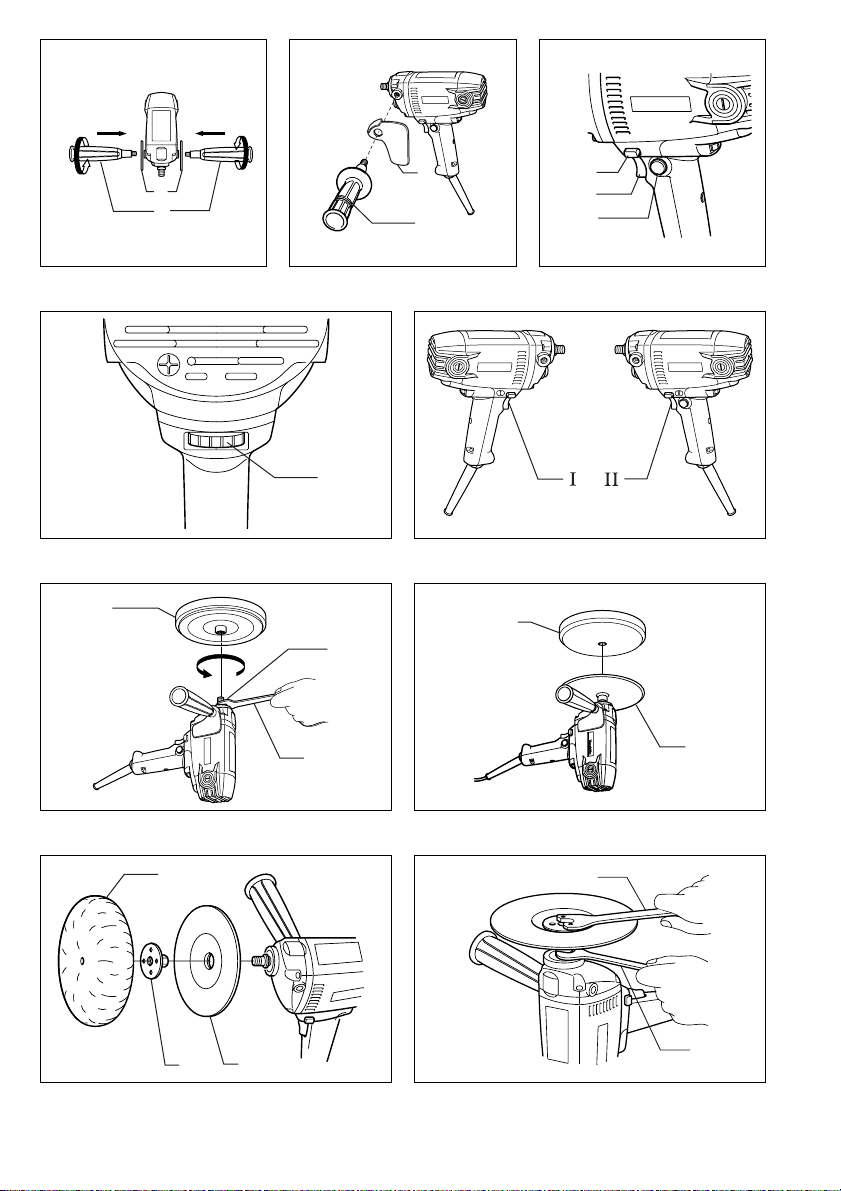
Installing side grip (auxiliary handle) & cover
(Fig. 1 & 2)
CAUTION:
Always be sure that the tool is switched off and
unplugged before installing or removing the side grip.
Install the cover, then screw the side grip on the tool
securely. The side grip and the cover can be installed on
either side of the tool. Always be sure that they are
installed securely.
Switch action (Fig. 3)
CAUTION:
Before plugging in the tool, always check to see that the
switch trigger actuates properly and returns to the “OFF”
position when released.
To start the tool, simply pull the trigger. Release the trigger to stop. For continuous operation, pull the trigger and
then push in the lock button.
To stop the tool from the locked position, pull the trigger
fully, then release it.
5

Speed adjusting dial (Fig. 4)
The rotating speed can be changed by turning the speed
adjusting dial to a given number setting from 1 to 5.
Higher speed is obtained when the dial is turned in the
direction of number 5. And lower speed is obtained when
it is turned in the direction of number 1. Refer to the table
below for the relationship between the number settings
on the dial and the approximate rotating speed.
-1
Number min
1–2 600–800
2–3 800–1,300
3–4 1,300–1,800
4–5 1,800–2,000
CAUTION:
• If the tool is operated continuously at low speeds
(speed adjusting dial: 1 – 3), the motor will get overloaded and heated up.
• The speed adjusting dial can be turned only as far as 5
and back to 1. Do not force it past 5 or 1, or the speed
adjusting function may no longer work.
The tools equipped with electronic function are easy to
operate because of the following features.
• Constant speed control Electronic speed control for
obtaining constant speed. Possible to get fine finish,
because the rotating speed is kept constant even under
load condition.
• Soft start feature Safety and soft start because of suppressed starting shock.
High-Low speed setting button (Fig. 3 & 5)
The tool speed can be changed instantly while the tool is
running. Depress the “ I” position for lowest speed and
depress “ II” position for a given number setting. The tool
speed cannot be changed when the button is in “ I ” position, even if you turn the speed adjusting dial. When you
turn the speed adjusting dial, always be sure that the button is depressed in “ II ” position.
(R.P.M.)
FOR USE AS A POLISHER
Installing or removing pad (Fig. 6)
CAUTION:
Always be sure that the tool is switched off and
unplugged before installing or removing the pad.
Hold the spindle with the wrench so that it cannot revolve.
Then screw the pad onto the spindle all the way. (The
pad can be used to install the optional sponge pad.)
To remove the pad, follow the installation procedure in
reverse.
Installing or removing sponge pad (Fig. 7)
CAUTION:
Always be sure that the tool is switched off and
unplugged before installing or removing the sponge pad.
To install the sponge pad, first remove all dirt or foreign
matter from the pad. Install the sponge pad to the pad.
To remove the pad, pull off it from the pad slowly.
Installing or removing the wool bonnet
(Fig. 8, 9 & 10)
CAUTION:
Always be sure that the tool is switched off and
unplugged before installing or removing the wool bonnet.
Mount the rubber pad onto the spindle. Screw the lock
nut onto the spindle. Hold the spindle firmly with the
wrench and tighten the lock nut using the lock nut
wrench. Fit the wool bonnet over the rubber pad. Tie a
bow knot and tuck the knot and any loose strings
between the wool bonnet and the rubber pad.
To remove the wool bonnet, follow the installation procedure in reverse.
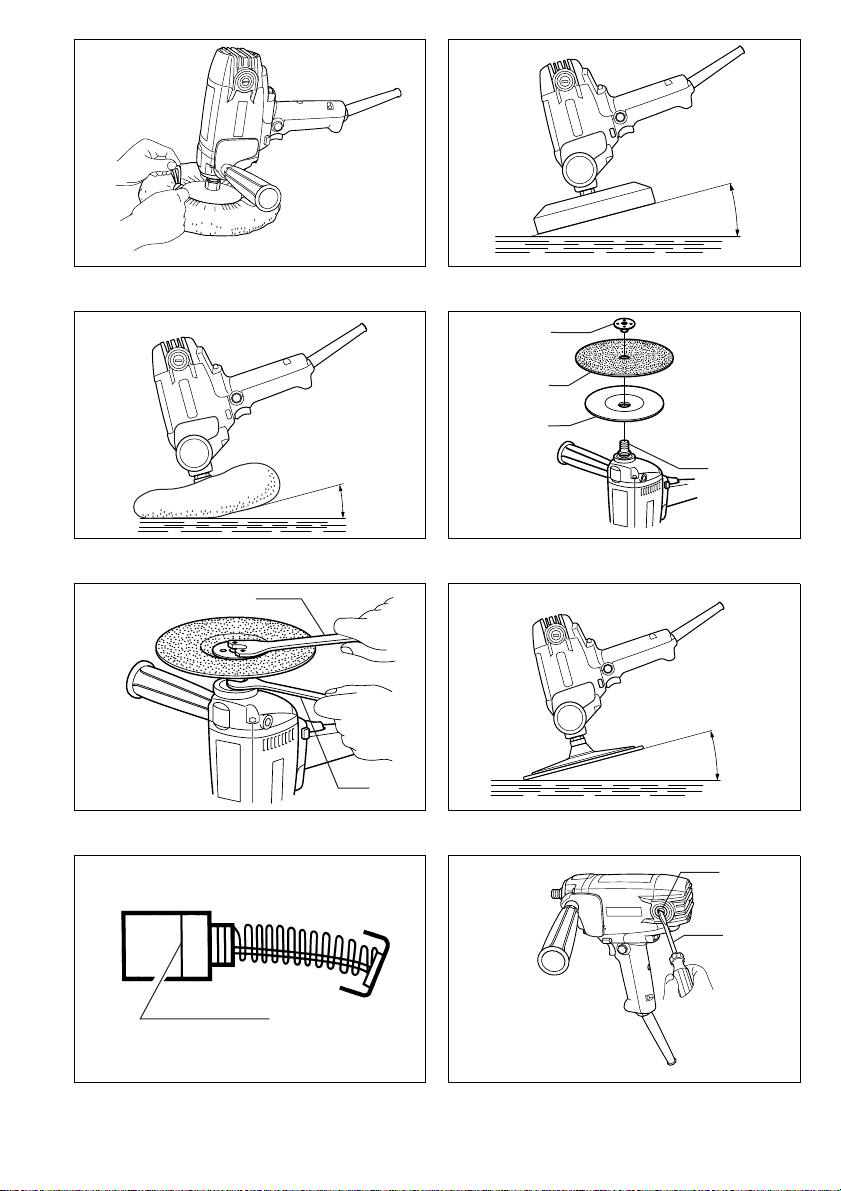
Polishing operation by sponge pad/wool
bonnet (Fig. 11 & 12)
CAUTION:
• Always wear safety glasses or a face shield during
operation.
• Apply slight pressure only. Excessive pressure will
result in poor performance and premature wear to the
sponge pad/wool bonnet.
When polishing, keep the sponge pad/wool bonnet at an
angle of about 15° to the workpiece surface.
FOR USE AS A SANDER
Installing or removing abrasive disc
(Fig. 13 & 14)
CAUTION:
Always be sure that the tool is switched off and
unplugged before installing or removing the abrasive
disc.
Mount the rubber pad onto the spindle. Fit the abrasive
disc on over the rubber pad and screw the lock nut onto
the spindle. Hold the spindle firmly with the wrench and
tighten the lock nut using the lock nut wrench.
To remove the abrasive disc, follow the installation procedure in reverse.
NOTE:
The rubber pad, abrasive disc, lock nut and lock nut
wrench are optional accessories.
Sanding operation (Fig. 15)
CAUTION:
• Always wear safety glasses or a face shield during
operation.
• Apply slight pressure only. Excessive pressure will
result in poor performance and premature wear to the
abrasive disc.
• Never run the tool without the abrasive disc. You may
seriously damage the pad.
Keep the abrasive disc at an angle of about 15° to the
workpiece surface.
6

MAINTENANCE
CAUTION:
Always be sure that the tool is switched off and
unplugged before carrying out any work on the tool.
Replacement of carbon brushes
(Fig. 16 & 17)
Replace carbon brushes when they are worn down to the
limit mark. Both identical carbon brushes should be
replaced at the same time.
To maintain product safety and reliability, repairs, maintenance or adjustment should be carried out by a Makita
Authorized Service Center.
7

NEDERLANDS
1Deksel
2 Zijhandgreep
3 Trekschakelaar
4 Vastzetknop
5 Snelheidsregelknop
6 Steunschijf
7As
Verklaring van algemene gegevens
8 Steeksleutel
9 Schuimrubberschijf
10 Wollen kap
11 Sluitmoer
12 Rubberen steunschijf
13 Nokkensleutel
14 Schuurschijf
15 Limietmarkering
16 Koolborsteldop
17 Schroevedraaier
18 Instelknop voor
hoog/laag toerental
TECHNISCHE GEGEVENS
Model PV7000C
Max. capaciteit
Schuimrubberschijf/Wollen kap ....................... 180 mm
Schuurschijf ..................................................... 180mm
Onbelast toerental (min
Totale lengte ....................................................... 210 mm
Netto gewicht ..........................................................2,0 kg
• In verband met ononderbroken research en ontwikke-
ling behouden wij ons het recht voor bovenstaande
technische gegevens te wijzigen zonder voorafgaande
kennisgeving.
• Opmerking: De technische gegevens kunnen van land
tot land verschillen.
Stroomvoorziening
De machine mag alleen worden aangesloten op een
stroombron van hetzelfde voltage als aangegeven op de
naamplaat, en kan alleen op enkel-fase wisselstroom
worden gebruikt. De machine is dubbel-geïsoleerd volgens de Europese standaard en kan derhalve ook op
een niet-geaard stopkontakt worden aangesloten.
Veiligheidswenken
Voor uw veiligheid dient u de bijgevoegde Veiligheidsvoorschriften nauwkeurig op te volgen.
-1
) ............................. 600–2000
AANVULLENDE
VEILIGHEIDSVOORSCHRIFTEN
1. Draag tijdens het gebruik van het gereedschap
altijd oog- en oorbeschermers. Draag indien
nodig ook andere persoonlijke veiligheidsuitrusting zoals een stofmasker, handschoenen, een
helm en een voorschoot. Draag voor alle zekerheid de veiligheidsuitrusting in geval van twijfel.
2. Zorg er altijd voor dat de machine is uitgescha-
keld en de stekker uit het stopcontact is getrokken alvorens enig onderhoud aan de machine uit
te voeren.
3. Accessoires moeten geschikt zijn voor minstens
het aanbevolen toerental dat op het waarschuwingslabel van de machine is aangeduid. Wielen
en andere accessoires die draaien met een snelheid boven het nominale toerental kunnen van
de machine worden weggeslingerd en verwonding veroorzaken.
4. Controleer de steunschijf zorgvuldig op scheu-
ren, beschadiging of vervorming alvorens de
machine te gebruiken. Vervang een gescheurde,
beschadigde of vervormde schijf onmiddellijk.
5. Controleer of het werkstuk stevig ondersteund
is.
6. Houd de machine stevig vast.
7. Houd uw handen uit de buurt van roterende
onderdelen.
8. Zorg ervoor dat de schuurschijf of de wollen
polijstschijf het werkstuk niet raakt voordat de
schakelaar wordt ingedrukt.
9. Kijk uit voor rondvliegende vonken wanneer u
metalen oppervlakken schuurt. Houd de
machine zo vast dat de vonken wegvliegen van
uzelf en andere personen of van ontvlambare
materialen.
10. Laat de machine niet alleen terwijl deze is ingeschakeld. Laat de machine alleen draaien wanneer u deze vasthoudt.
11. Denk eraan dat de schijf blijft draaien nadat het
gereedschap is uitgeschakeld.
12. Raak het bewerkte oppervlak niet direct na het
schuren (polijsten) aan, aangezien dit zeer heet
kan zijn en brandwonden kan veroorzaken.
13. Indien de werkplaats uiterst heet en vochtig is, of
erg vervuild is door geleidend stof, gebruik dan
een kortsluitschakelaar (30 mA) om een veilige
bediening te verzekeren.
14. Gebruik de machine niet op materialen die
asbest bevatten.
15. Gebruik geen water of slijpolie.
16. Ventileer goed uw werkplaats wanneer u het
gereedschap gebruikt om te schuren.
17. Gebruik altijd het juiste stofmasker/gasmasker
dat nodig is voor het materiaal en de toepassing
waarmee u werkt.
18. Zorg dat de ventilatieopeningen niet geblokkeerd zijn wanneer u in stoffige omgevingen
werkt. Indien stof verwijderd moet worden, trek
dan eerst de stekker uit het stopcontact (gebruik
niet-metalen voorwerpen) en let op dat u geen
interne onderdelen van het gereedschap beschadigt.
BEWAAR DEZE VOORSCHRIFTEN.
BEDIENINGSVOORSCHRIFTEN
Installeren van de zijhandgreep (hulphandgreep) en
het deksel (Fig.1 en 2)
LET OP:
Schakel het gereedschap altijd uit en haal zijn netsnoer
uit het stopcontact alvorens de zijhandgreep te installeren of te verwijderen.
Installeer het deksel en schroef vervolgens de zijhandgreep stevig vast op het gereedschap. De zijhandgreep
en het deksel kunnen aan een van beide zijden van het
gereedschap worden bevestigd. Zorg ervoor dat ze stevig bevestigd worden.
17

Werking van de trekschakelaar (Fig. 3)
LET OP:
Alvorens de machine op netstroom aan te sluiten, dient u
altijd te controleren of de trekschakelaar juist werkt en bij
het loslaten naar de “OFF” positie terugkeert.
Om de machine in te schakelen, drukt u gewoon de trekschakelaar in. Om te stoppen dient u de trekschakelaar
los te laten. Voor continu gebruik, eerst de trekschakelaar en dan de vergrendelknop indrukken.
Om de machine vanuit de vergrendelde stand te stoppen, de trekschakelaar helemaal indrukken en deze dan
loslaten.
Toerentalregelknop (Fig. 4)
U kunt de draaisnelheid veranderen door de toerentalregelknop te draaien en in te stellen op een cijfer van
1 tot 5.
De snelheid verhoogt wanneer u de draaiknop in de richting van het cijfer 5 draait. De snelheid verlaagt wanneer
u deze in de richting van het cijfer 1 draait. Zie de onderstaande tabel voor de verhouding tussen de cijfers op de
draaiknop en de approximatieve draaisnelheid.
-1
Cijfer min
1–2 600–800
2–3 800–1300
3–4 1300–1800
4–5 1800–2000
LET OP:
• Wanneer u het gereedschap (toerentalregelknop: 1 – 3)
achtereen bij een lage snelheid gebruikt, kan de motor
overbelast en oververhit worden.
• De toerentalregelknop kan niet verder dan 5 en niet
verder terug dan 1 worden gedraaid. Forceer de draaiknop niet voorbij 5 of 1, aangezien de toerentalregeling
dan niet meer juist zal werken.
Gereedschappen die voorzien zijn van een elektronische
functie zijn gemakkelijk te bedienen dank zij de volgende
kenmerken.
• Handhaving van een constant toerental Elektronische
toerentalregeling verzekert een constant toerental. U
kunt fijn afwerken, aangezien de draaisnelheid tijdens
belast draaien constant gelijk wordt gehouden.
• Zachte start De aanloopschok wordt onderdrukt zodat
u veilig kunt werken en zacht kunt starten.
Instelknop voor hoog/laag toerental (Fig. 3 en 5)
Het toerental van het gereedschap kan onmiddellijk worden veranderd terwijl het gereedschap draait. Druk de “ I ”
zijde in om het laagste toerental te krijgen, en druk de
“ II ” zijde in om een van de genummerde snelheden te
kiezen. Wanneer de “ I” zijde van de knop is ingedrukt,
kan het toerental niet worden veranderd, zelfs niet wanneer u de toerentalregelknop draait. Als u het toerental
met de toerentalregelknop wilt veranderen, moet u eerst
de “ II” zijde van de knop indrukken.
(RPM)
GEBRUIK ALS EEN POLIJSTMACHINE
Installeren of verwijderen van de steunschijf (Fig. 6)
LET OP:
Schakel het gereedschap altijd uit en haal het netsnoer
uit het stopcontact alvorens de steunschijf te installeren
of te verwijderen.
Houd de as met een sleutel op zijn plaats zodat deze niet
kan draaien. Schroef daarna de steunschijf vast op de
as. (De steunschijf kan worden gebruikt om de los verkrijgbare schuimrubberschijf te installeren.)
Voer de installatieprocedure in de omgekeerde volgorde
uit om de steunschijf te verwijderen.
Installeren of verwijderen van de
schuimrubberschijf (Fig.7)
LET OP:
Schakel het gereedschap altijd uit en haal het netsnoer
uit het stopcontact alvorens de schuimrubberschijf te
installeren of te verwijderen.
Verwijder alle vuil of verontreinigingen van de steunschijf
alvorens de schuimrubberschijf te installeren. Installeer
daarna de schuimrubberschijf op de steunschijf.
Om de schuimrubberschijf te verwijderen, trekt u deze
langzaam van de steunschijf af.
Installeren of verwijderen van de wollen kap
(Fig.8,9en10)
LET OP:
Schakel het gereedschap altijd uit en haal het netsnoer
uit het stopcontact alvorens de wollen kap te installeren
of te verwijderen.
Monteer de rubberen steunschijf op de as. Schroef de
borgmoer op de as. Houd de as goed op zijn plaats met
de sleutel en draai de borgmoer vast met de borgmoersleutel. Monteer de wollen kap over de rubberen steunschijf. Maak een strikknoop en stop de knoop en
eventuele losse touwtjes weg tussen de wollen kap en de
rubberen steunschijf.
Voer de installatieprocedure in de omgekeerde volgorde
uit om de wollen kap te verwijderen.
Polijsten met de schuimrubberschijf/wollen kap
(Fig. 11 en 12)
LET OP:
• Draag tijdens het werk altijd een veiligheidsbril of een
gezichtsbescherming.
• Oefen alleen lichte dr uk uit. Overmatige druk zal
slechte prestaties en vroegtijdige slijtage van de
schuimrubberschijf/wollen kap veroorzaken.
Houd de schuimrubberschijf/wollen kap tijdens het polijsten onder een hoek van ongeveer 15° vanaf het werkstukoppervlak.
18

GEBRUIK ALS EEN SCHUURMACHINE
Installeren of verwijderen van de schuurschijf
(Fig. 13en 14)
LET OP:
Schakel het gereedschap altijd uit en haal het netsnoer
uit het stopcontact alvorens de schuurschijf te installeren
of te verwijderen.
Monteer de rubberen steunschijf op de as. Monteer de
schuurschijf over de rubberen steunschijf en schroef de
borgmoer op de as. Houd de as goed op zijn plaats met
de sleutel en draai de borgmoer vast met de borgmoersleutel.
Voer de installatieprocedure in de omgekeerde volgorde
uit om de schuurschijf te verwijderen.
OPMERKING:
De rubberen steunschijf, de schuurschijf, de borgmoer en
de borgmoersleutel zijn los verkrijgbare accessoires.
Schuren (Fig.15)
LET OP:
• Draag tijdens het werk altijd een veiligheidsbril of een
gezichtsbescherming.
• Oefen alleen lichte druk uit. Overmatige druk zal
slechte prestaties en vroegtijdige slijtage van de
schuurschijf veroorzaken.
• Schuur nooit met het gereedschap zonder de schuurschijf. Als u dit doet, kan de steunschijf ernstig beschadigd raken.
Houd de schuurschijf tijdens het schuren onder een hoek
van ongeveer 15° vanaf het werkstukoppervlak.
ONDERHOUD
LET OP:
Zorg er altijd voor dat de machine is uitgeschakeld en de
stekker uit het stopcontact is verwijderd alvorens onderhoud aan de machine uit te voeren.
Vervangen van koolborstels (Fig. 16en 17)
Vervang de borstels wanneer ze tot aan de aangegeven
limiet zijn afgesleten. Beide koolborstels dienen tegelijkertijd te worden vervangen.
Opdat het gereedschap veilig en betrouwbaar blijft, dienen alle reparaties, onderhoud of afstellingen te worden
uitgevoerd bij een erkend Makita service centrum.
19

GB ACCESSORIES
CAUTION:
These accessories or attachments are recommended for
use with your Makita tool specified in this manual. The
use of any other accessories or attachments might
present a risk of injury to persons. The accessories or
attachments should be used only in the proper and
intended manner.
F ACCESSOIRES
AT T E N TI O N :
Ces accessoires ou ces fixations sont recommandés
pour l’utilisation de l’outil Makita spécifié dans ce manuel.
L’utilisation d’autres accessoires ou fixations peut
présenter un risque de blessures. Les accessoires ou les
fixations ne devront être utilisés que dans le but et de la
manière prévus.
P ACESSÓRIOS
PRECAUÇÃO:
Estes acessórios ou acoplamentos são os
recomendados para uso na ferramenta MAKITA
especifidada neste manual. A utilização de qualquer
outro acessórios ou acoplamento poderá ser perigosa
para o operador. Os acessórios ou acoplamentos devem
ser utilizados de maneira adequada e apenas para os
fins a que se diestinam.
DK TILBEHØR
ADVARSEL:
Dette udstyr og tilbehør bør anvendes sammen med
Deres Makita maskine, sådan som det er beskrevet i
denne vejledning. Anvendelse af andet udstyr eller
tilbehør kan medføre personskade. Tilbehøret bør kun
anvendes til det, det er beregnet til.
D ZUBEHÖR
VORSICHT:
Das mitgelieferte Zubehör ist speziell für den Gebrauch
mit dem in dieser Betriebsanleitung angegebenen
Makita-Elektrowerkzeug vorgesehen. Bei Verwendung
von Fremdzubehör in Verbindung mit dieser Maschine
besteht Verletzungsgefahr.
I ACCESSORI
ATTENZIONE:
Gli accessori o raccordi seguenti sono raccomandati per
l’uso con l’utensile Makita specificato in questo manuale.
L’uso di qualsiasi altro accessorio o raccordo potrebbe
causare pericoli di ferite alle persone. Gli accessori o
raccordi devono essere usati soltanto nel modo corretto
e specificato.
NL ACCESSOIRES
LET OP:
Deze accessoires of hulpstukken zijn aanbevolen voor
gebruik met uw Makita gereedschap dat in deze
gebruiksaanwijzing is beschreven. Het gebruik van
andere accessoires of hulpstukken kan gevaar voor
persoonlijke verwondingen opleveren. De accessoires of
hulpstukken dienen alleen op de juiste en
voorgeschreven manier te worden gebruikt.
E ACCESORIOS
PRECAUCIÓN:
Estos accesorios o acoplamientos están recomendados
para usar con la herramienta Makita especificada en
este manual. Con el uso de cualquier otro accesorio o
acoplamiento se podría correr el riesgo de producir
heridas a personas. Los accesorios o acoplamientos
deberán usarse solamente de la manera apropiada y
para la que han sido designados.
S TILLBEHÖR
FÖRSIKTIGHET:
Dessa tillbehör eller tillsatser rekommenderas endast för
användning tillsammans med din Makita maskin som
specifieras i denna bruksanvisning. Användning av andra
tillbehör eller tillsatser kan medföra risk för personskador.
Tillbehören och tillsatserna får endast användas på
lämpligt och där för avsett sätt.
N TILBEHØR
NB!
Dette tilbehøret eller utstyret anbefales til å brukes
sammen med din Makita maskin som er spesifisert i
denne bruksanvisningen. Bruk av annet tilbehør eller
utstyr kan medføre en risiko for personskader. Tilbehør
og utstyr må bare brukes som spesifisert og bare til det
det er beregnet til.
SF LISÄVARUSTEET
VA RO :
Tässä käyttöohjeessa mainitun Makita-koneen kanssa
suositellaan seuraavien lisälaitteiden ja -varusteiden
käyttöä. Minkä tahansa muun lisälaitteen tai -varusteen
käyttäminen saattaa aiheuttaa loukkaantumisvaaran.
Lisälaitteita ja -varusteita tulee käyttää ainoastaan niille
sopivalla tavalla.
GR ΕΞΑΡΤΗΜΑΤΑ
ΠΡΟΣΟΧΗ:
Αυτά τα εξαρτήµατα ή προσαρτήµατα συνιστώνται
για χρήση µε το µηχάνηµα της Μάκιτα που
περιγράφεται στο εγχειρίδιο αυτο. Η χρήση άλλων
εξαρτηµάτων ή προσαρτηµάτων µπορεί να είναι
επικίνδυνη για τραυµατισµ% ατ%µων. Τα εξαρτήµατα
ή προσαρτήµατα πρέπει να χρησιµοποιούνται µ%νο
µε το σωστ% και προτιθέµενο τρ%πο.
39

• Rubber pad
• Plateau caoutchouc
• Elastischer Schleifteller
• Platorello di gomma
• Rubberen steunschijf
• Almohadilla de goma
• Disco de borracha
• Gummibagskive
• Gummiplatta
• Gummipute
• Kumilevy
• Ελαστικ% υπ%θεµα
• Sponge pad
• Coussinet-éponge
• Schaumstoffkissen
• Tampone di spugna
• Schuimrubberschijf
• Boina de esponja
• Almofada esponjosa
• Svampepude
• Svampdyna
• Skumgmmipute
• Vaahtokumityyny
• Σπογγοειδές πέλµα
• Wool bonnet
• Peau de mouton
• Polierhaube
• Cuffia di lana
• Wollen kap
• Caperuza de lana
• Baina de lã
• Polerhætte
• Lammullshättan
• Ullhette
• Villakansi
• Μάλλινο κάλυµµα
• Abrasive disc
• Disque abrasif
• Fiberscheibe
• Disco abrasivo
• Schuurschijf
• Disco abrasivo
• Disco abrasivo
• Slibeskive
• Sliprondell
• Slipeskive
• Hiomalaikka
• Λειαντικ%ς δίσκος
• Lock nut
•Écrou
• Flanschmutter
• Flangia esterna
•Sluitmoer
• Tuerca de fijación
• Contraporca
• Sikringsmøtrik
• Låsmutter
• Låsemutter
• Lukkomutteri
• Κοχλίας κλειδώµατος
Grid: 16, 20, 24, 30, 50, 80, 100, 120
40

• Lock nut wrench
• Clé à ergots
• Stirnlochschlüssel
• Chiave per controdadi
• Nokkensleutel
• Llave para la tuerca de fijación
• Chave de pinos
• Tapnøgle
• Låsmutternyckel
• Skrunøkkel til låsemutter
• Lukkomutterin avain
• Κλειδί κοχλία κλειδώµατος
•Wrench
• Clés
• Gabelschlüssel
•Chiave
•Sleutel
•Llave
•Chave
•Nøgle
• Skruvnyckel
• Skrunøkkel
• Kiintoavain
•Κλειδί
41

ENGLISH
EC-DECLARATION OF CONFORMITY
The undersigned, Yasuhiko Kanzaki, authorized by
Makita Corporation, 3-11-8 Sumiyoshi-Cho, Anjo, Aichi
446-8502 Japan declares that this product
manufactured by Makita Corporation in Japan is in compliance with the following standards or standardized documents,
in accordance with Council Directives, 73/23/EEC,
89/336/EEC and 98/37/EC.
(Serial No. : series production)
HD400, EN50144, EN55014, EN61000
FRANÇAISE
DÉCLARATION DE CONFORMITÉ CE
Je soussigné, Yasuhiko Kanzaki, mandaté par Makita Corporation, 3-11-8 Sumiyoshi-Cho, Anjo, Aichi 446-8502
Japan, déclare que ce produit
fabriqué par Makita Corporation au Japon, est conformes
aux normes ou aux documents normalisés suivants,
HD400, EN50144, EN55014, EN61000
conformément aux Directives du Conseil, 73/23/CEE,
89/336/CEE et 98/37/EG.
(No. de série: production en série)
DEUTSCH
Hiermit erklärt der Unterzeichnete, Yasuhiko Kanzaki,
Bevollmächtigter von Makita Corporation, 3-11-8
Sumiyoshi-Cho, Anjo, Aichi 446-8502 Japan, daß dieses
von der Firma Makita Corporation in Japan hergestellte
Produkt
gemäß den Ratsdirektiven 73/23/EWG, 89/336/EWG
und 98/37/EG mit den folgenden Normen bzw. Normendokumenten übereinstimmen:
CE-KONFORMITÄTSERKLÄRUNG
(Serien-Nr.: Serienproduktion)
HD400, EN50144, EN55014, EN61000.
ITALIANO
DICHIARAZIONE DI CONFORMITÀ
CON LE NORME DELLA COMUNITÀ EUROPEA
Il sottoscritto Yasuhiko Kanzaki, con l’autorizzazione
della Makita Corporation, 3-11-8 Sumiyoshi-Cho, Anjo,
Aichi 446-8502 Japan, dichiara che questo prodotto
(Numero di serie: Produzione in serie)
fabbricato dalla Makita Corporation in Giappone è conformi alle direttive europee riportate di seguito:
HD400, EN50144, EN55014, EN61000
secondo le direttive del Consiglio 73/23/CEE,
89/336/CEE e 98/37/CE.
NEDERLANDS
EG-VERKLARING VAN CONFORMITEIT
De ondergetekende, Yasuhiko Kanzaki, gevolmachtigd
door Makita Corporation, 3-11-8 Sumiyoshi-Cho, Anjo,
Aichi 446-8502 Japan verklaart dat dit produkt
vervaardigd door Makita Corporation in Japan voldoet
aan de volgende normen of genormaliseerde documenten,
in overeenstemming met de richtlijnen van de Raad
73/23/EEC, 89/336/EEC en 98/37/EC.
(Serienr. : serieproduktie)
HD400, EN50144, EN55014, EN61000
ESPAÑOL
DECLARACIÓN DE CONFORMIDAD DE LA CE
El abajo firmante, Yasuhiko Kanzaki, autorizado por
Makita Corporation, 3-11-8 Sumiyoshi-Cho, Anjo, Aichi
446-8502 Japan, declara que este producto
(Número de serie: producción en serie)
fabricado por Makita Cor poration en Japón cumple las
siguientes normas o documentos normalizados,
HD400, EN50144, EN55014, EN61000
de acuerdo con las directivas comunitarias, 73/23/EEC,
89/336/EEC y 98/37/CE.
42
Yasuhiko Kanzaki
Director Amministratore
Directeur Directeur
Direktor Director
CE 2000
MAKITA INTERNATIONAL EUROPE LTD.
Michigan Drive, Tongwell, Milton Keynes,
Bucks MK15 8JD, ENGLAND

PORTUGUÊS
DECLARAÇÃO DE CONFORMIDADE DA CE
O abaixo assinado, Yasuhiko Kanzaki, autorizado pela
Makita Corporation, 3-11-8 Sumiyoshi-Cho, Anjo, Aichi
446-8502 Japan, declara que este produto
(N. de série: produção em série)
fabricado pela Makita Corporation no Japão obedece às
seguintes normas ou documentos normalizados,
HD400, EN50144, EN55014, EN61000
de acordo com as directivas 73/23/CEE, 89/336/CEE e
98/37/CE do Conselho.
DANSK
EU-DEKLARATION OM KONFORMITET
Undertegnede, Yasuhiko Kanzaki, med fuldmagt fra
Makita Corporation, 3-11-8 Sumiyoshi-Cho, Anjo, Aichi
446-8502 Japan, erklærer hermed, at dette produkt
(Løbenummer: serieproduktion)
fremstillet af Makita Corporation i Japan, er i overensstemmelse med de følgende standarder eller normsættende dokumenter,
HD400, EN50144, EN55014, EN61000
i overensstemmelse med Rådets Direktiver 73/23/EEC,
89/336/EEC og 98/37/EC.
SVENSKA
EG-DEKLARATION OM ÖVERENSSTÄMMELSE
Undertecknad, Yasuhiko Kanzaki, auktoriserad av Makita
Corporation, 3-11-8 Sumiyoshi-Cho, Anjo, Aichi 446-8502
Japan deklarerar att denna produkt
tillverkad av Makita Corporation i Japan, uppfyller kraven
i följande standard eller standardiserade dokument,
HD400, EN50144, EN55014, EN61000
i enlighet med EG-direktiven 73/23/EEC, 89/336/EEC
och 98/37/EC.
(serienummer: serieproduktion)
NORSK
Undertegnede, Yasuhiko Kanzaki, med fullmakt fra
Makita Corporation, 3-11-8 Sumiyoshi-Cho, Anjo, Aichi
446-8502 Japan bekrefter herved at dette produktet
fabrikert av Makita Corporation, Japan, er i overensstemmelse med følgende standarder eller standardiserte
dokumenter:
i samsvar med Råds-direktivene, 73/23/EEC,
89/336/EEC og 98/37/EC.
EUs SAMSVARS-ERKLÆRING
(Serienr. : serieproduksjon)
HD400, EN50144, EN55014, EN61000,
SUOMI
VAKUUTUS EC-VASTAAVUUDESTA
Makita Corporation, 3-11-8 Sumiyoshi-Cho, Anjo, Aichi
446-8502 Japan valtuuttamana allekirjoittanut, Yasuhiko
Kanzaki, vakuuttaa että tämä tämä tuote
valmistanut Makita Corporation Japanissa vastaa seu-
(Sarja nro : sarjan tuotantoa)
raavia standardeja tai stardardoituja asiakirjoja
HD400, EN50144, EN55014, EN61000
neuvoston direktiivien 73/23/EEC, 89/336/EEC ja
98/37/EC mukaisesti.
ΕΛΛΗΝΙΚΑ
Ο υπογράφων, Yasuhiko Kanzaki, εξουσιοδοτηµένος
απ% την εταιρεία Makita Corporation, 3-11-8
Sumiyoshi-Cho, Anjo, Aichi 446-8502 Japan, δηλώνει
%τι αυτ% το προϊ%ν
κατασκευασµένο απ% την Εταιρεία Makita στην
Ιαπωνία, βρίσκεται σε συµφωνία µε τα ακ%λουθα
πρ%τυπα ή τυποποιηµένα έγγραφα,
σύµφωνα µε τις Οδηγίες του Συµβουλίου,
73/23/EEC, 89/336/EEC και 98/37/ΚE.
∆ΗΛΩΣΗ ΣΥΜΜΟΡΦΩΣΗΣ ΕΚ
(Αύξων Αρ.: παραγωγή σειράς)
HD400, EN50144, EN55014, EN61000
Yasuhiko Kanzaki
Director Direktor
DirektørJohtaja
CE 2000
Direktör ∆ιευθυντής
MAKITA INTERNATIONAL EUROPE LTD.
Michigan Drive, Tongwell, Milton Keynes,
Bucks MK15 8JD, ENGLAND
43

ENGLISH
The typical A-weighted sound pressure level is 82 dB (A).
The noise level under working may exceed 85 dB (A).
The typical weighted root mean square acceleration value is
not more than 2.5 m/s
Noise and Vibration
– Wear ear protection. –
2
.
PORTUGUÊS
O nível normal de pressão sonora A é 82 dB (A).
O nível de ruído durante o trabalho pode exceder 85 dB (A).
O valor médio da aceleração é inferior a 2,5 m/s
Ruído e vibração
– Utilize protectores para os ouvidos –
2
.
FRANÇAISE
Le niveau de pression sonore pondéré A type est de 82 dB (A).
Le niveau de bruit en fonctionnement peut dépasser 85 dB (A).
L’accélération pondérée ne dépasse pas 2,5 m/s
Bruit et vibrations
– Porter des protecteurs anti-bruit. –
2
.
DEUTSCH
Geräusch- und Vibrationsentwicklung
Der typische A-bewertete Schalldruckpegel beträgt 82 dB (A).
Der Lärmpegel kann während des Betriebs 85 dB (A) überschreiten.
Der gewichtete Effektivwert der Beschleunigung beträgt nicht
mehr als 2,5 m/s
– Gehörschutz tragen. –
2
.
ITALIANO
Il livello di pressione sonora pesata secondo la curva A è di
82 dB (A).
Il livello di rumore durante il lavoro potrebbe superare gli
85 dB (A).
Il valore quadratico medio di accellerazione non supera i
2
2,5 m/s
Rumore e vibrazione
– Indossare i paraorecchi. –
.
NEDERLANDS
Het typische A-gewogen geluidsdrukniveau is 82 dB (A).
Tijdens het werken kan het geluidsniveau 85 dB (A) overschrijden.
De typische gewogen effectieve versnellingswaarde is niet
meer dan 2,5 m/s
Geluidsniveau en trilling
– Draag oorbeschermers. –
2
.
ESPAÑOL
El nivel de presión sonora ponderada A es de 82 dB (A).
El nivel de ruido en condiciones de trabajo puede que sobrepase los 85 dB (A).
El valor ponderado de la aceleración no sobrepasa los
2
.
2,5 m/s
Ruido y vibración
– Póngase protectores en los oídos. –
DANSK
Det typiske A-vægtede lydtryksniveau er 82 dB (A).
Støjniveauet under arbejde kan overstige 85 dB (A).
Den vægtede effektive accelerationsværdi overstiger ikke
2
.
2,5 m/s
Lyd og vibration
– Bær høreværn. –
SVENSKA
Den typiska-A-vägda ljudtrycksnivån är 82 dB (A).
Bullernivån under pågående arbete kan överstiga 85 dB (A).
Det typiskt vägda effektivvärdet för acceleration överstiger
inte 2,5 m/s
Buller och vibration
– Använd hörselskydd –
2
.
NORSK
Det vanlige A-belastede lydtrykksnivå er 82 dB (A).
Under bruk kan støynivået overskride 85dB (A).
Den vanlig belastede effektiv-verdi for akselerasjon overskrider ikke 2,5 m/s
Støy og vibrasjon
– Benytt hørselvern. –
2
.
SUOMI
Tyypillinen A-painotettu äänenpainetaso on 82 dB (A).
Melutaso työpaikalla saattaa ylittää 85 dB (A).
Tyypillinen kiihtyvyyden painotettu tehollisarvo ei ylitä
2
.
2,5 m/s
Melutaso ja tärinä
– Käytä kuulosuojaimia. –
ΕΛΛΗΝΙΚΑ
Η τυπική Α-µετρούµενη ηχητική πίεση είναι 82 dB (A).
Η ένταση ήχου υπο συνθήκες εργασίας µπορεί να
µπερβεί τα 85 dB (A).
Η τυπική αξία της µετρούµενης ρίζας του µέσου
τετραγώνου της επιτάχυνσης δεν ξεπερνά τα 2,5 m/s
Θρυβος και κραδασµς
– Φοράτε ωτοασπίδες. –
2
.
44

454647


Makita Corporation
Anjo, Aichi, Japan
Made in Japan
884356D994
 Loading...