

Makita DPC 7001, DPC 9500, DPC 9501, Power Cut DPC 7000, Power Cut DPC 7001 Owner's And Safety Manual
...
Owner’s and
Safety Manual
Manuel d’emploi
et de securite
for Power Cut
(page
2 - 25)
de
la
decoupeuse
(page
26
-
49)
DPC 7000, DPC 7001
DPC 9500, DPC 9501
WARNING!
Read this Owner’s Manual carefully before putting the Power Cut into operation and strictly observe the
Safety Manual! Improper use can cause serious injury! Preserve this Manual carefully!
ATTENTION!
Lire attentivement ce manuel avant la premiere mise en service et observer absolument les
prescriptions de securite! Une utilisation incorrecte de la decoupeuse peut entrainer des blessures
graves! Conservez avec soin ce manuel d’emploi!
Thank you for purchasing a MAKITA product!
Congratulations on choosing a MAKITA Power Cut cutoff saw!
We are confident that you will be satisfied with this modern piece
of equipment
.
Like our chain saws. the MAKITA Power Cuts
feature specially designed high-performance engines with outstanding power-to-weight ratios. for heavy-duty yet lightweight
tools
.
Other advantages of the MAKITA Power Cuts:
Sturdyconstruction and high reliability
.
Maintenance-free electronic ignition. hermetically sealed to
protect against dust and moisture
.
Vibration damping with the 2-mass system
(D2M)
for tireless
working even when guiding the Power Cut by hand
.
Three-stage air-filter system for reliable operation even in very
dusty conditions
.
Two options for mounting the cutter attachment: Either centrally. for good balance when guiding the unit manually. or on
the side. for flush cuts along walls or curbsides or horizontally
directly above the ground
.
Extensive line of synthetic-resin and diamond cutting discs.
and trolley with vibration damping. dust catcher. and several
systems for water supply
to
the cutting disc
.
We want you
to
be satisfied with your MAKITA product
.
In order
to
guarantee the optimal function and performance of
your Power Cut and
to
ensure your personal safety we would
request you
to
perform the following:
Read this owner’s manual carefully before putting the
Power Cut into operation for the first time. and strictly
observe the safety regulations
.
Table of contents
Page
Packing
.............................................
Delivery inventory
............................
Symbols
...............................................................................
3
SAFETY PRECAUTIONS
.....................................................
4
General precautions
........................................................
4
Protective equipment
...................................................
4-5
Fuels/ Refuelling
.............................................................
5
Putting into operation
.......................................................
5
Cutting discs
....................................................................
6
Kickbackand lock-in
Cutting metal
...................................................................
8
Cutting masonry
...........................................................
8.9
Transport and storage
.....................................................
9
Working behavior/ Method of working
....
Technical data
...................................................................
11
Denomination of components
.........................................
11
PUTTING INTO OPERATION
............................................
12
Installing the drive arm
Tightening the V.belt
......................................................
13
Mounting thecutting disc
.........................................
13-14
Fuels
/
Refuelling
.....................................................
14-15
Starting the engine
.........................................................
15
Cold-starting 15
Warm-starting
................................................................
15
If the engine won’t start
..................................................
15
Stopping the engine
.......................................................
15
Adjusting the carburetor ..................................................
16
MAINTENANCE
..................................................................
17
Changing the V-belt
.......................................................
17
Cleaning the protection hood
.........................................
17
Cleaning /changing the air filter
....................................
18
Replacing the spark plug
...............................................
18
Replacing the suction head
...........................................
19
Replacing the starter cable
Replacing the return spring
Instructions for periodic maintenance
............................
23
Cutting attachment in central / side position .................
20
Repositioning the cutting attachment
20-21
Repositioning the cutting
and mounting the cutting disc
.
12-13
(DPC
7000,
DPC 7001)
.
(DPC 9500, DPC
9501)
.................................................
21
and pressure water system
............................................
22
SPECIAL ACCESSORIES ..................................................
22
Diamond cutting discs, trolley. water tank
Service, spare parts and guarantee ..........................
23-24
Trouble shooting
.
24
Extract from spar
............................................
25
Accessories
...................................................................
25
Service centers in the USA
....................................
50
Notes
............................
51
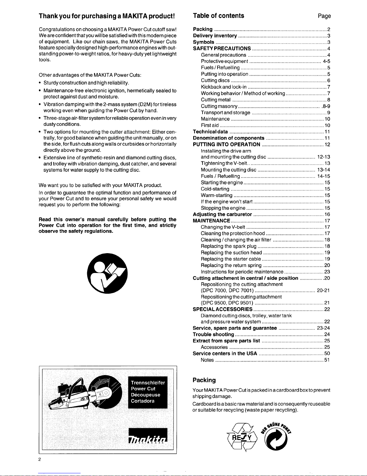
Packing
Your MAKITA Power Cut is packed in acardboard box
to
prevent
shipping damage
.
Cardboard is a basic raw material and is consequently reuseable
or suitable for recycling (waste paper recycling)
.
2
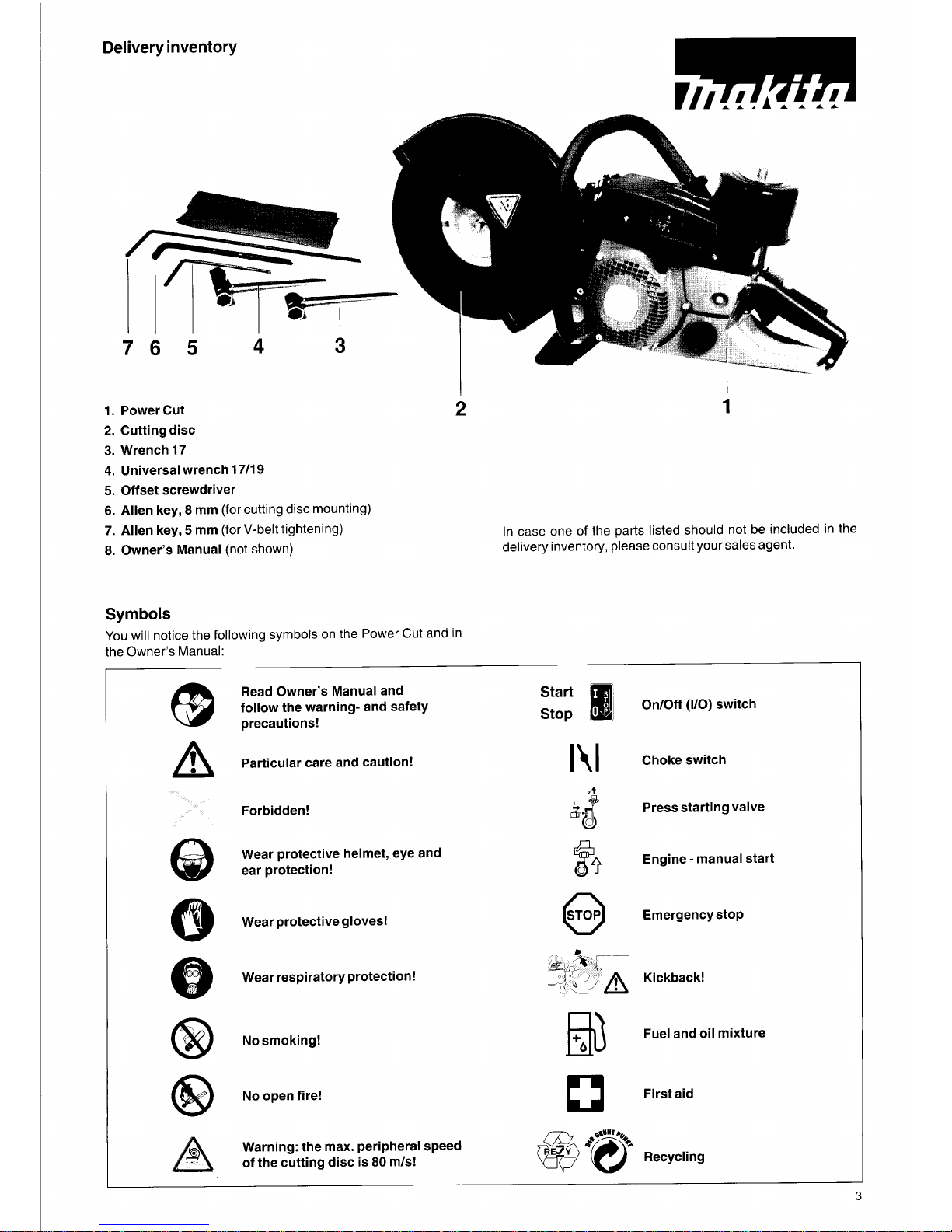
Delivery inventory
76
5
4
3
I
1.
PowerCut
2
2.
Cutting disc
3.
Wrench17
4.
Universal wrench 17/19
5.
Offset screwdriver
6.
Allen key, 8 mm (for cutting disc mounting)
7.
Allen key, 5 mm (for V-belt tightening)
8.
Owner’s Manual (not shown)
Sym
bok
You
will notice the following symbols on the Power Cut and in
the Owner’s Manual:
I
1
In case one of the parts listed should not be included in the
delivery inventory, please consult your sales agent.
Read Owner’s Manual and
follow the warning- and safety
precautions!
Particular care and caution!
Forbidden!
Wear protective helmet, eye and
ear protection!
Wear protective gloves!
Wear respiratory protection!
No
smoking!
No
open fire!
Warning: the max. peripheral speed
of the cutting disc is
80
m/s!
~
Start
a
On/Off (VO) switch
Stop
L
It
I
Choke switch
zt
Press starting valve
k-8
Engine - manual Start
@
Emergency stop
it
Kickback!
Fuel and oil mixture
I3
First aid
0
Recycling
3
SAFETY PRECAUTIONS
General precautions
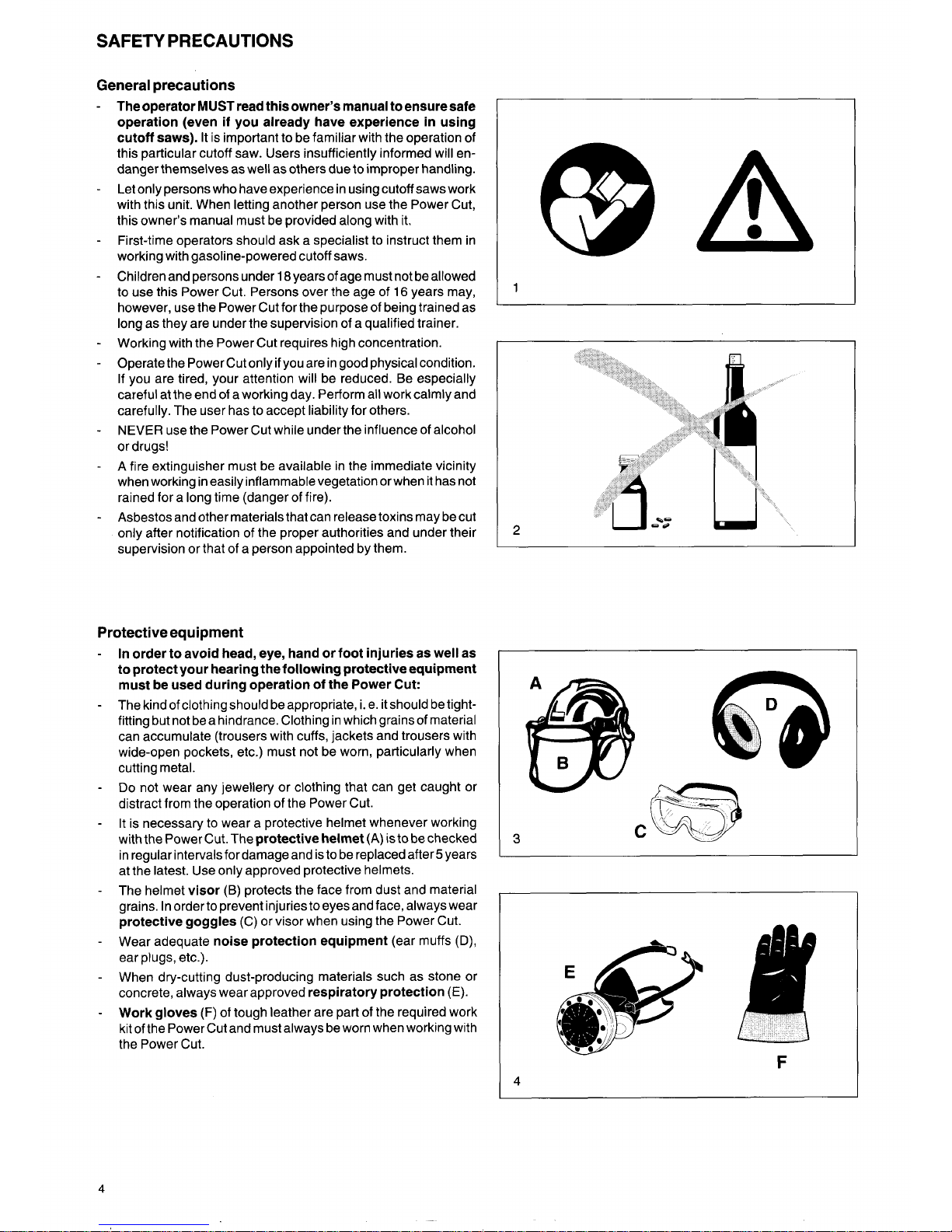
In order to avoid head, eye, hand or foot injuries
as
well
as
to protect your hearing the following protective equipment
must be used during operation of the Power Cut:
The kind of clothing should be appropriate,
i.
e. it should be tightfitting but not be a hindrance. Clothing in which grains of material
can accumulate (trousers with cuffs, jackets and trousers with
wide-open pockets, etc.) must not be worn, particularly when
cutting metal.
Do
not wear any jewellery or clothing that can get caught or
distract from the operation of the Power Cut.
It is necessary to wear a protective helmet whenever working
with the Power Cut. The
protective helmet
(A) is to be checked
in regular intervalsfor damage and is to be replaced after5 years
The operator
MUST
read this owner’s manual to ensure safe
operation (even if you already have experience in using
cutoff saws).
It
is important to be familiar with the operation of
this particular cutoff saw. Users insufficiently informed will endanger themselves as well as others due
to
improper handling.
Let only persons who have experience in using cutoff saws work
with this unit. When letting another person use the Power Cut,
this owner’s manual must be provided along with
it.
First-time operators should ask a specialist
to
instruct them in
working with gasoline-powered cutoff saws.
C
3
Children and persons under 18years of age must not be allowed
to
use this Power Cut. Persons over the age of 16 years may,
however, use the Power Cut for the purpose of being trained as
long as they are under the supervision of a qualified trainer.
Working with the Power Cut requires high concentration.
Operate the Power Cut only
if
you are in good physical condition.
If you are tired, your attention will be reduced. Be especially
careful at the end
of
a working day. Perform all work calmly and
carefully. The user has to accept liability for others.
NEVER
use the Power Cut while under the influence of alcohol
or drugs!
A fire extinguisher must be available in the immediate vicinity
when working in easily inflammable vegetation or when it has not
rained for a long time (danger of fire).
Asbestos and other materials that can release toxins may be cut
only after notification of the proper authorities and under their
supervision or that of a person appointed by them.
Protective equipment
2
4
-
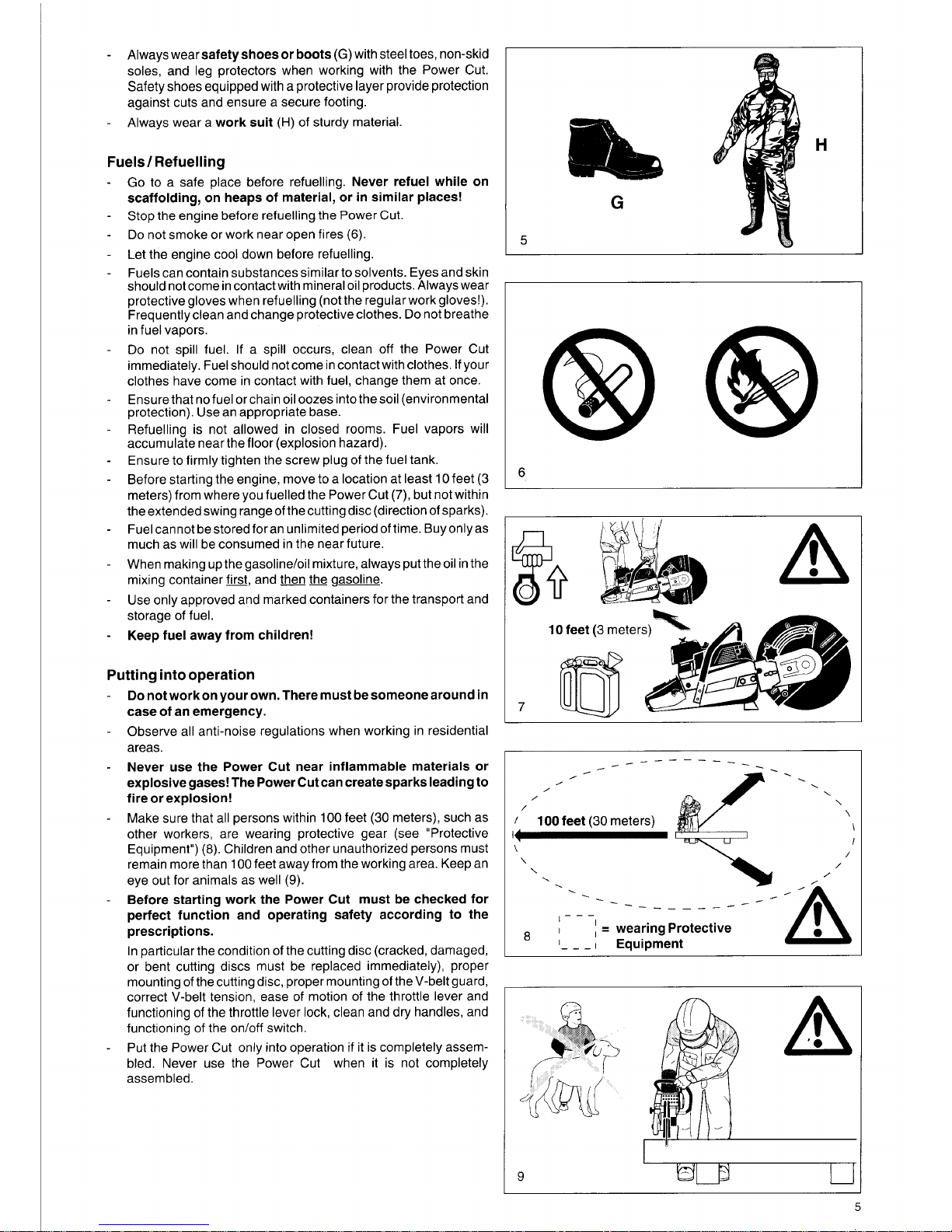
Always
wearsafetyshoesor boots
(G)
with steel toes, non-skid
soles, and leg protectors when working with the Power Cut.
Safety shoes equipped with a protective layer provide protection
against cuts and ensure a secure footing.
Always wear a
work suit
(H)
of sturdy material.
-
Fuels
/
Refuelling
Go
to a safe place before refuelling.
Never refuel while on
scaffolding, on heaps of material, or in similar places!
Stop the engine before refuelling the Power Cut.
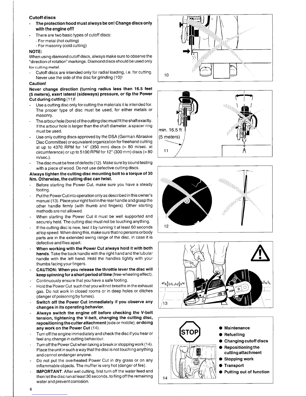
Do
not smoke or work near open fires
(6).
G
5
H
Let the engine cool down before refuelling.
I
Fuels can contain substances similar to solvents. Eyes and skin
should not come in contact with mineral oil products. Always wear
protective gloves when refuelling (not the regularworkgloves!).
Frequently clean and change protective clothes.
Do
not breathe
in fuel vapors.
Do
not spill fuel.
If
a spill occurs, clean off the Power Cut
immediately. Fuel should not come in contact with clothes. If your
clothes have come in contact with fuel, change them at once.
Ensurethat no fuel or chain oil oozes intothesoil (environmental
protection). Use an appropriate base.
Refuelling is not allowed in closed rooms. Fuel vapors will
accumulate near the floor (explosion hazard).
Ensure to firmly tighten the screw plug
of
the fuel tank
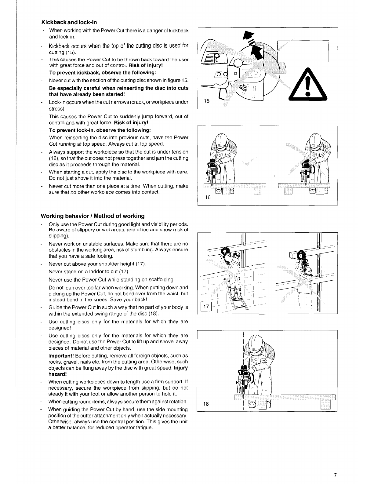
Before starting the engine, move to a location at least
10
feet
(3
meters) from where you fuelled the Power Cut
(7),
but not within
the extended swing range of the cutting disc (direction of sparks)
Fuel cannot be stored for an unlimited period of time. Buy only as
much as will be consumed in the near future
When making up the gasolineloil mixture, always put the oil in the
mixing container
flrst,
and then the gasoline.
Use only approved and marked containers for the transport and
6
storage of fuel.
Keep fuel away from children!
Putting into operation
-
Do
not work on your own. There must be someone around in
case of an emergency.
Observe all anti-noise regulations when working in residential
areas.
Never use the Power Cut near inflammable materials or
explosive gases! The Power Cut can create sparks leading to
fire or explosion!
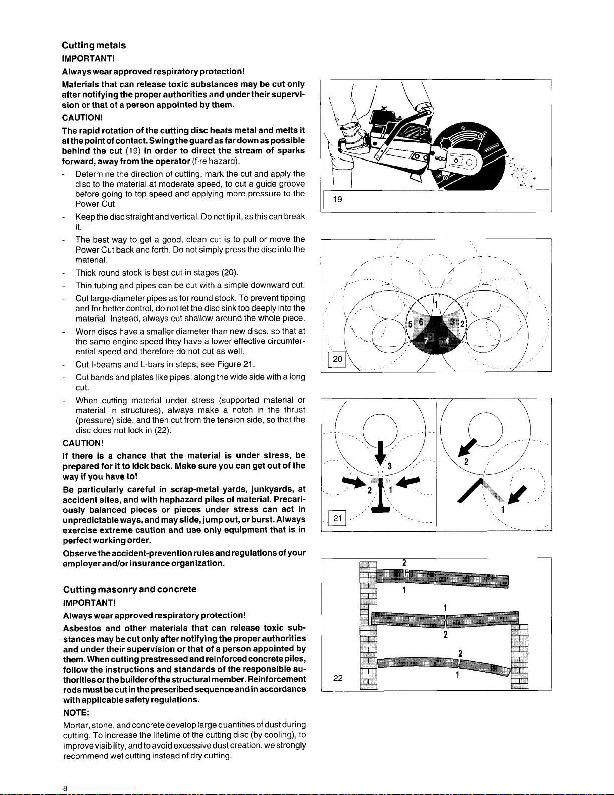
Make sure that all persons within
100
feet
(30
meters), such as
other workers, are wearing protective gear (see "Protective
Equipment")
(8).
Children and other unauthorized persons must
remain more than
100
feet away from the working area. Keep an
eye out for animals as well
(9).
Before starting work the Power Cut must be checked for
perfect function and operating safety according to the
prescriptions.
In particular the condition of the cutting disc (cracked, damaged,
or bent cutting discs must be replaced immediately), proper
mounting of the cutting disc, proper mounting of
the V-belt
guard,
correct V-belt tension, ease of motion of the throttle lever and
functioning of the throttle lever lock, clean and dry handles, and
functioning of the onloff switch.
Put the Power Cut only into operation
if
it is completely assembled. Never use the Power Cut when it is not completely
assem bled.
-
-
-
-
-
10
feet
(3
meters)
7
/
,
,
/
/
/
\
1
lOOfeet
(30
meters)
'I
I
\
\
\
-_
__-_--
-
.
.
.
\
\
I--1
;
=
wearingprotective
Equipment
81
-
- -
I
19
5
Cutoff discs
-
The protection hood must always be on! Change discs only
with the engine
off!
There are two basic types of cutoff discs:
-
For metal (hot cutting)
-
For masonry (cold cutting)
-
NOTE:
When using diamond cutoff discs, always make sure to observe the
"direction of rotation" markings. Diamond discs should be used only
for
cutting
metal.
-
Cutoff discs are intended only for radial loading, i.e. for cutting.
Never use the side of the disc for grinding
(1
O)!
Caution!
10
Never change direction (turning radius less than
16.5
feet
(5
meters), exert lateral (sideways) pressure, or tip the Power
Cut during cutting
(1
l)!
-
Use a cutting disc only for cutting the materials it is intended for.
The proper type of disc must be used, for either metals or
masonry.
The arbour hole (bore) of the cutting disc must fit the shaft exactly.
If
the arbour hole is larger than the shaft diameter, a spacer ring
must be used.
Use only cutting discs approved by the DSA (German Abrasive
Disc Committee)
or
equivalent organization for freehand cutting
at up to
4370
RPM for
14"
(350
mm) discs
(=
80
m/sec. at
circumference) or up to
51
00
RPM for
12" (300
mm) discs
(=
80
mlsec.).
-
-
6
-
The disc must be free of defects
(1
2).
Make sure by sound testing
with a piece of wood.
Do
not use defective cutting discs.
Always tighten the cutting disc mounting bolt to a torque of
30
Nm. Otherwise, the cutting disc can twist.
Before starting the Power Cut, make sure you have a steady
footing.
Putthe PowerCut intooperation onlyasdescribed in thisowner's
manual
(13).
Place yourrightfoot inthe rear handleandgraspthe
other handle firmly (with thumb and fingers). Other starting
methods are not allowed.
When starting the Power Cut it must be well supported and
securely held. The cutting disc must not be touching anything.
If the cutting disc is new, test it by running it at least
60
seconds
at top speed. When doing this, make sure that no persons or body
parts are in the extended swing range of the disc, in case it is
defective and flies apart.
When working with the Power Cut always hold it with both
hands.
Take the back handle with the right hand and the tubular
handle with the left hand. Hold the handles tightly with your
thumbs facing your fingers.
CAUTION: When you release the throttle lever the disc will
keepspinningforashort period of time
(free-wheelingeffect).
Continuously ensure that you have a safe footing.
Hold the Power Cut such that you will not breathe in the exhaust
gas.
Do
not work in closed rooms or in deep holes or ditches
(danger of poisoning by fumes).
Switch off the Power Cut immediately if you observe any
changes in its operating behavior.
Always switch the engine off before checking the V-belt
tension, tightening the V-belt, changing the cutting disc,
repositioning thecutter attachment
(side or middle),
or doing
any work on the Power Cut
(14).
Turn off the engine immediately and check the disc if you hear or
feel any change in cutting behaviour.
Turn off the Power Cut when taking a break or stopping work
(1
4).
Place the unit in such a way that the disc is not touching anything
and cannot endanger anyone.
Do
not put the overheated Power Cut in dry grass or on any
inflammable objects. The muffler is very hot (danger of fire).
IMPORTANT:
After wet cutting, first turn off the water feed and
then let the disc run at least
30
seconds, to fling off the remaining
water and prevent corrosion.
0
Maintenance
0
Refuelling
0
Changing cutoff discs
14
0
Repositioning the
0
Stopping work
0
Transport
0
Putting out of function
cutting attachment
Kickbackand lock-in
When working with the Power Cut there is a danger of kickback
and lock-in.
Kickback occurs when the
top
of
the cutting disc is used
for
cutting (15).
This causes the Power Cut to be thrown back toward the user
with great force and out of control.
Risk
of
injury!
To
prevent kickback, observe the following:
Never cut with the section of the cutting disc shown in figure 15.
Be especially careful when reinserting the disc into cuts
that have already been started!
Lock-in occurs when the
cut
narrows (crack, or workpiece under
stress).
This causes the Power Cut to suddenly jump forward, out of
control and with great force.
Risk
of
injury!
To
prevent lock-in, observe
the
following:
When reinserting the disc into previous cuts, have the Power
Cut running at top speed. Always cut at top speed.
Always support the workpiece
so
that the cut is under tension
(1
6),
so
that the cut does not press together and jam the cutting
disc as it proceeds through the material.
When starting a cut, apply the disc to the workpiece with care.
Do
not just shove it into the material.
Never cut more than one piece at a time! When cutting, make
sure that no other workpiece comes into contact.
Working behavior / Method
of
working
-
Only use the Power Cut during good light and visibility periods.
Be aware
of
slippery
or
wet areas, and
of
ice and snow (risk
of
slipping).
Never work on unstable surfaces. Make sure that there are no
obstacles in the working area, risk of stumbling. Always ensure
that you have a safe footing.
Never cut above your shoulder height (17).
Never stand on a ladder to cut (17).
Never use the Power Cut while standing on scaffolding.
Do
not lean over
too
far when working. When putting down and
picking up the Power Cut, do not bend over from the waist, but
instead bend in the knees. Save your back!
Guide the Power Cut in such a way that no part of your body is
within the extended swing range of the disc
(18).
Use cutting discs only for the materials for which they are
designed!
Use cutting discs only for the materials for which they are
designed. Do not use the Power Cut to lift up and shovel away
pieces of material and other objects.
Important!
Before cutting, remove all foreign objects, such as
rocks, gravel, nails etc. from the cutting area. Otherwise, such
objects can be flung away by the disc with great speed.
Injury
hazard!
When cutting workpieces down to length use a firm support.
If
necessary, secure the workpiece from slipping, but
do
not
steady it with your foot or allow another person to hold it.
When cutting round items, alwayssecure them against rotation.
When guiding the Power Cut by hand, use the side mounting
position
of
the cutter attachment only when actually necessary.
Otherwise, always use the central position. This gives the unit
a better balance, for reduced operator fatigue.
-
-
-
-
-
-
-
-
-
-
-
18
7
Cutting
metals
IMPORTANT!
Always wear approved respiratory protection!
Materials that can release toxic substances may be cut only
after notifying the proper authorities and under their supervision or that of a person appointed by them.
CAUTION!
The rapid rotation of the cutting disc heats metal and melts
it
at the point of contact. Swing the guard as far down as possible
behind the cut
(19)
in
order to direct the stream of sparks
forward, away from the operator (fire hazard).
Determine the direction of cutting, mark the cut and apply the
disc to the material at moderate speed, to cut a guide groove
before going to top speed and applying more pressure to the
Power Cut.
Keepthediscstraightandvertical. Donottipit, asthiscan break
it.
The best way to get a good, clean cut is to pull or move the
Power Cut back and forth.
Do
not simply press the disc into the
material.
Thick round stock is best cut in stages
(20).
Thin tubing and pipes can be cut with a simple downward cut.
Cut large-diameter pipes as for round stock.
To
prevent tipping
and for better control, do not let the disc sink too deeply into the
material. Instead, always cut shallow around the whole piece.
Worn discs have a smaller diameter than new discs,
so
that at
the same engine speed they have a lower effective circumferential speed and therefore do not cut as well.
Cut I-beams and L-bars in steps; see Figure
21.
Cut bands and plates like pipes: along the wide side with a long
cut.
When cutting material under stress (supported material or
material in structures), always make a notch in the thrust
(pressure) side, and then cut from the tension side,
so
that the
disc does not lock in
(22).
CAUTION!
If there is a chance that the material
is
under stress, be
prepared for it to kick back. Make sure you can get out of the
way if you have
to!
Be particularly careful in scrap-metal yards, junkyards, at
accident sites, and with haphazard piles of material. Precariously balanced pieces or pieces under stress can act in
unpredictable ways, and may slide, jump out, or burst. Always
exercise extreme caution and use only equipment that is
in
perfect working order.
Observe the accident-prevention rules and regulations of your
employer andlor insurance organization.
Cutting masonry and concrete
IMPORTANT!
Always wear approved respiratory protection!
Asbestos and other materials that can release toxic sub-
stances may be cut only after notifying the proper authorities
and under their supervision or that of a person appointed by
them. When cutting prestressed and reinforced concrete piles,
follow the instructions and standards of the responsible authoritiesorthe builder of thestructural member. Reinforcement
rods must be cut
in
the prescribed sequence and
in
accordance
with applicable safety regulations.
NOTE:
Mortar, stone, and concrete develop large quantities of dust during
cutting.
To
increase the lifetime of the cutting disc (by cooling), to
improve visibility, and to avoid excessive dust creation, we strongly
recommend wet cutting instead of dry cutting.
I
l9
I
/
\
....
./
.
22
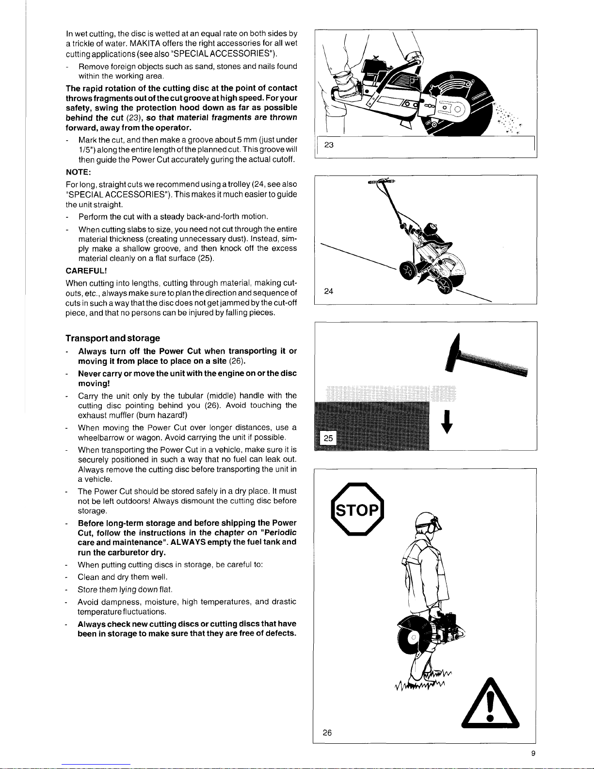
In wet cutting, the disc is wetted at an equal rate on both sides by
a trickle of water. MAKITA offers the right accessories for all wet
cutting applications (see
also
"SPECIAL ACCESSORIES").
-
Remove foreign objects such as sand, stones and nails found
within the working area.
The rapid rotation of the cutting disc at the point of contact
throwsfragmentsout ofthecutgrooveat high speed. For your
safety, swing the protection hood down as far as possible
behind the cut
(23),
so
that material fragments are thrown
forward, away from the operator.
-
Mark the cut, and then make a groove about 5 mm
(just
under
1/5")
along the entire length of the planned cut. This groove will
then guide the Power Cut accurately guring the actual cutoff.
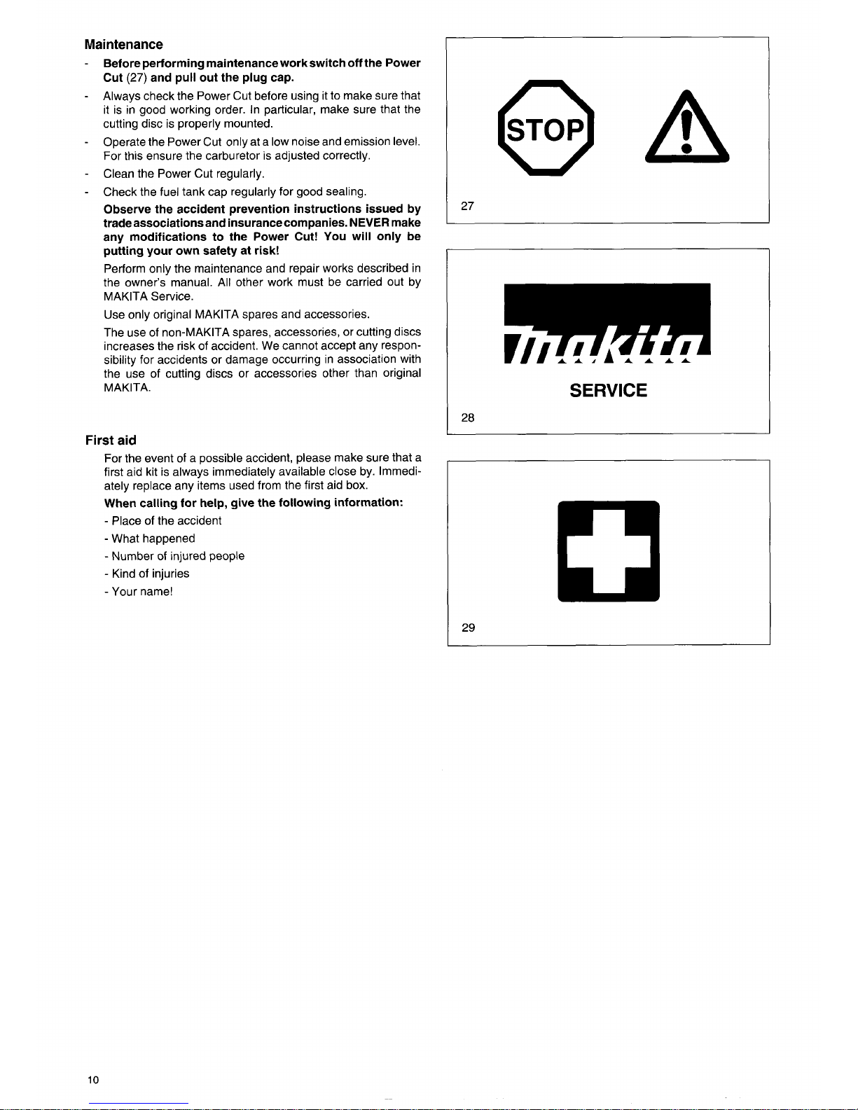
NOTE:
For long, straight cuts we recommend using a trolley (24, see also
"SPECIAL ACCESSORIES"). This makes it much easier
to
guide
the unit straight.
-
-
Perform the cut with a steady back-and-forth motion.
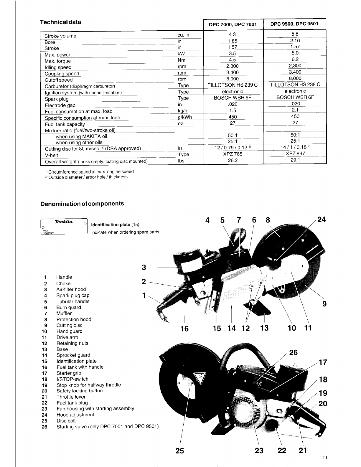
When cutting slabs to size, you need not cut through the entire
material thickness (creating unnecessary dust). Instead, sim-
ply make a shallow groove, and then knock off the excess
material cleanly on a flat surface (25).
CAREFUL!
When cutting into lengths, cutting through material, making cut-
outs, etc., always make sure
to
plan the direction and sequence
of
cuts in such a way that the disc does not get jammed by the cut-off
piece, and that no persons can be injured by falling pieces.
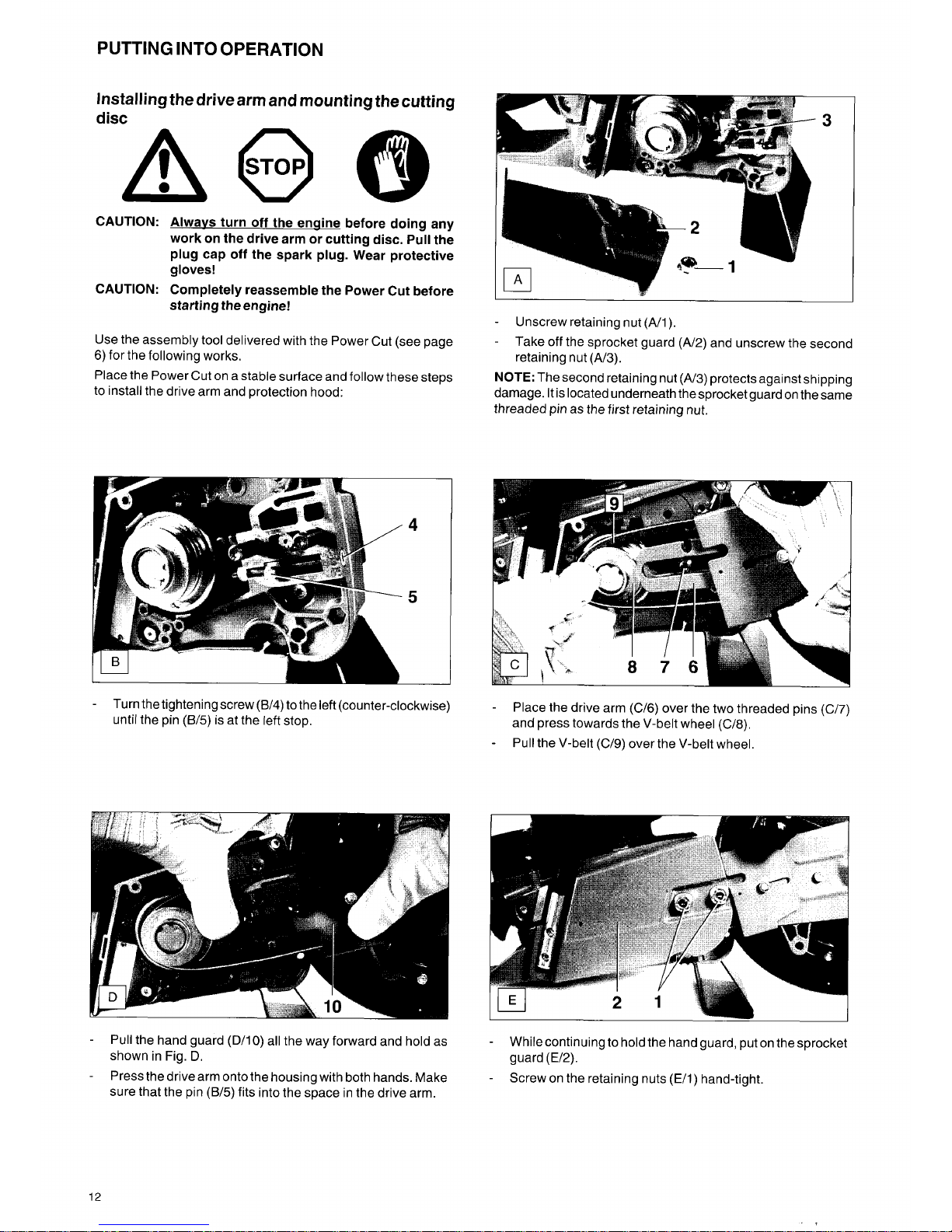
Transport and storage
Always turn off the Power Cut when transporting it or
moving it from place to place on a site (26).
Never carry or move the unit with the engine on or the disc
moving!
Carry the unit only by the tubular (middle) handle with the
cutting disc pointing behind
you
(26).
Avoid touching the
exhaust muffler (burn hazard!)
When moving the Power Cut over longer distances, use a
wheelbarrow or wagon. Avoid carrying the unit if possible.
When transporting the Power Cut in a vehicle, make sure it is
securely positioned in such a way that
no
fuel can leak out.
Always remove the cutting disc before transporting the unit in
a vehicle.
The Power Cut should be stored safely in
a
dry place.
It
must
not be left outdoors! Always dismount the cutting disc before
storage.
Before long-term storage and before shipping the Power
Cut, follow the instructions in the chapter on "Periodic
care and maintenance". ALWAYS empty the fuel tank and
run the carburetor dry.
When putting cutting discs in storage, be careful to:
Clean and dry them well.
Store them lying down flat.
Avoid dampness, moisture, high temperatures, and drastic
temperature fluctuations.
Always check new cutting discs or cutting discs that have
been in storage to make sure that they are free of defects.
23
24
4
26
9
Maintenance
-
Before performing maintenance workswitch off the Power
Cut
(27)
and pull out the plug cap.
Always check the Power Cut before using it to make sure that
it is in good working order. In particular, make sure that the
cutting disc is properly mounted.
Operate the Power Cut only at a low noise and emission level.
For this ensure the carburetor
is
adjusted correctly.
Clean the Power Cut regularly.
Check the fuel tank cap regularly for good sealing.
Observe the accident prevention instructions issued by
tradeassociations and insurancecompanies.
NEVER
make
any modifications to the Power Cut! You will only be
putting your own safety at risk!
Perform only the maintenance and repair works described in
the owner’s manual. All other work must be carried out by
MAKITA Service.
Use only original MAKITA spares and accessories.
The use of non-MAKITA spares, accessories, or cutting discs
increases the risk of accident. We cannot accept any responsibility for accidents or damage occurring in association with
the use of cutting discs or accessories other than original
M AKITA.
-
-
-
-
First
aid
For the event
of
a possible accident, please make sure that a
first aid kit is always immediately available close by. Immediately replace any items used from the first aid box.
When calling for help, give the following information:
-
Place of the accident
-
What happened
-
Number of injured people
-
Kind of injuries
-
Your
name!
I
27
SERVICE
I
28
29
10
I
Technical data
DPC 7000, DPC 7001
4.3
Stroke volume
cu.
in
~_________
Bore
~__-_________
--in__
Stroke
Max power kW
_________ppppp--
Max torque
Nm-
Idling speed rPm
Coupling speed
rpm-
Cutoff speed
rPm
Carburetor
(diaphragm carburetor)
p~---~-
Type__
Spark plug Type_
~
_____
~~
~_________
-___________
~~
In
~
-__________________
_________pp_________~~
~p~~
__
_________
~-.p
_______
__
p____~-~-
~_________
p~
Ignition system
(with speed limitation)
Type
p~_________
__
~
~__
~__________p-p-~
--~p
in
Electrodegap
_________
_______~
_______~
_______~
~
Fuel consumption at max. load
Specific consumption at max. load g/kWh
Fuel tank capacity
oz
~
Mixture ratio (fuel/two-stroke oil)
-
when using MAKITA
oil
-
when using other oils
~-
____________________p~
_________-
-_______ _________
_______
__________________pp_______p__
Cutting disc for
80
m/sec.
'1
(DSA approved) in
Type
V-beL
__
_________~
__.
p-~ p____
Overall weight
(tanks empty, cutting disc mounted)
Ibs
__-p_______~__~~_______
__________
_______
_________~
DPC
9500,
DPC 9501
5.8
Circumference speed at max. engine speed
*I
Outside diameter/ arbor hole / thickness
Denomination
of
components
Identification plate
(15)
I
Indicate when ordering spare parts
Made
8n
Germany
1
2
3
4
5
6
7
8
9
10
11
12
13
14
15
16
17
18
19
20
21
22
23
24
25
26
2 16
1.57
6.2
2,300
3,400
8,000
TILLOTSON
HS
239C
electronic electronic
~
BOSCH WSR
6F
________________
1
85
1.57
4.5
2,300
3,400
8,000
TILLOTSON HS 239
C
BOSCH WSR 6F
~_________
_________ _________~-
~_________
3.5 5.0
~
____p
~~_________
~p
~
_________~_________-
~_________
-p~
-~p
-_______
__~
.....................
______________
~~p
26.2 29.1
I
45768
124
3-
2
--
1,
16 15 14 12 13 10 11
Handle
Choke
Air-filter hood
Spark plug cap
Tubular handle
Burn guard
Muffler
Protection
hood
Cutting disc
Hand guard
Drive arm
Retaining nuts
Base
Sprocket guard
Identification plate
Fuel tank with handle
Starter grip
I/STOP-switch
Stop knob for halfway throttle
Safety locking button
Throttle lever
Fuel tank plug
Fan housing with starting assembly
Hood adjustment
Disc bolt
Starting valve (only DPC
7001
and DPC 9501)
25 23 22 21
11
PUTTING INTO OPERATION
Installing the drive arm and mounting the cutting
disc
CAUTION: Alwavs turn off the enqine before doing any
work on the drive arm or cutting disc. Pull the
plug cap off the spark plug. Wear protective
gloves!
CAUTION: Completely reassemble the Power Cut before
starting the engine!
Use the assembly
tool
delivered with the Power Cut (see page
6) for the following works.
Place the Power Cut on a stable surface and follow these steps
to install the drive arm and protection hood:
-
Turn the tightening screw
(B/4)
to the left (counter-clockwise)
until the pin
(B/5)
is at the left stop.
I-
-
Unscrew retaining nut (Ah).
-
Take off the sprocket guard (A/2) and unscrew the second
retaining nut (A/3).
NOTE:
The second retaining nut
(A/3)
protects against shipping
damage. It is located underneath thesprocket guard on the same
threaded pin as the first retaining nut.
-
Place the drive arm (C/6) over the two threaded pins (C/7)
and press towards the V-belt wheel (C/8).
Pull the V-belt (C/9) over the V-belt wheel.
-
I
I
-
Pull the hand guard (D/10) all the way forward and hold as
shown in Fig.
D.
Press the drive arm onto the housing with both hands. Make
sure that the pin
(B/5)
fits into the space in the drive arm.
-
While continuing to hold the hand guard, put on the sprocket
guard
(E/2).
Screw on the retaining nuts (Ell) hand-tight.
-
-
12
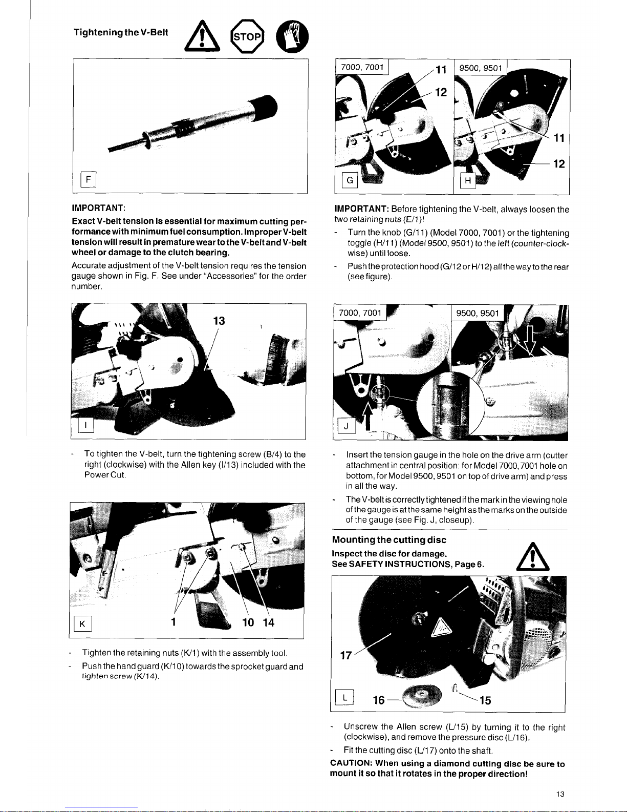
Tightening the V-Belt
IMPORTANT:
Exact V-belt tension is essential for maximum cutting performance with minimum fuel consumption. Improper V-belt
tension will result in premature wear to the V-belt and V-belt
wheel or damage to the clutch bearing.
Accurate adjustment of the V-belt tension requires the tension
gauge shown in Fig.
F.
See under “Accessories” for the order
number.
-
To tighten the V-belt, turn the tightening screw
(B/4)
to the
right (clockwise) with the Allen key (1/13) included with the
Power Cut.
-
-
Tighten the retaining nuts (K/1) with the assembly
tool
Push the hand guard (W10) towards the sprocket guard and
tighten
screw
(K/14).
I- I-
IMPORTANT:
Before tightening the V-belt, always loosen the
two retaining nuts (E/l)!
-
Turn the knob (GI1 1) (Model 7000,7001) or the tightening
toggle (H/11) (Model
9500,
9501)
to
the left (counter-clock-
wise) until loose.
Push the protection hood (G/12 or H/12) all the wayto the rear
(see figure).
-
-
Insert the tension gauge in the hole
on
the drive arm (cutter
attachment
in
central position: for Model 7000,7001 hole on
bottom, for Model
9500,9501
on top of drive arm) and press
in all the way.
-
TheV-beltiscorrectlytightenedifthemarkin
theviewing hole
of
the gauge
is
at the same height as the marks on the outside
of
the gauge (see Fig.
J,
closeup).
Mounting the cutting disc
m
Inspect the disc for damage.
See
SAFETY INSTRUCTIONS,
Page
6.
-
Unscrew the Allen screw (L/15) by turning it
to
the right
(clockwise), and remove the pressure disc (L/16).
Fit the cutting disc (L/17) onto the shaft.
-
CAUTION:
When using a diamond cutting disc be sure to
mount it
so
that it rotates in the proper direction!
13
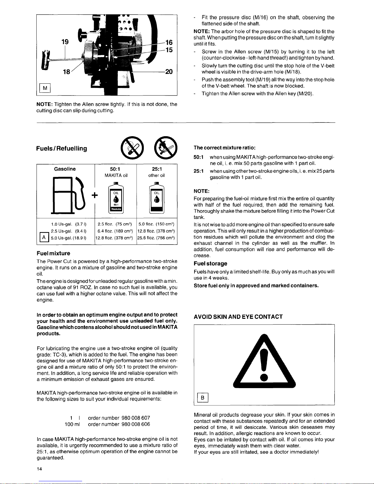
-
Fit the pressure disc (M/16) on the shaft, observing the
flattened side of the shaft.
NOTE:
The arbor hole of the pressure disc is shaped to fit the
shaft. When putting the pressurediscon the shaft, turn itslightly
until it fits.
-
Screw in the Allen screw (M/15) by turning it to the left
(counter-clockwise
-
left-hand thread!) and tighten by hand.
Slowly turn the cutting disc until the stop hole of the V-belt
wheel is visible in the drive-arm hole (M/18).
Push the assembly tool (M/19)
all
the way into the stop hole
of the V-belt wheel. The shaft is now blocked.
Tighten the Allen screw with the Allen key (M/20).
-
-
-
NOTE:
Tighten the Allen screw tightly. If this is not done, the
cutting disc can slip during cutting.
@
Fuels/
Refuelling
Gasoline
I
50:l
1
.O
Us-gal. (3.7
I)
2.5 Us-gal. (9.4
I)
A
5.0 Us-gaL(18.9
I)
2.5
floz.
(75 cm3)
6.4
floz.
(189 cm3)
12.8 floz. (378 cm3)
25:l
other
oil
5.0
floz.
(150 cm3)
2.8
floz.
(378 cm3)
5.6 floz. (756 cm3)
Fuel mixture
The Power Cut is powered by a high-performance two-stroke
engine. It runs on a mixture of gasoline and two-stroke engine
oil.
The engine is designed for unleaded regular gasoline with amin.
octane value of 91
ROZ.
In case no such fuel is available, you
can use fuel with a higher octane value. This will not affect the
engine.
In order to obtain an optimum engine output and to protect
your health and the environment use unleaded fuel only.
Gasoline which contens alcohol should not used in MAKITA
products.
For lubricating the engine use a two-stroke engine oil (quality
grade:
TC-3),
which is added to the fuel. The engine has been
designed for use of MAKITA high-performance two-stroke en-
gine oil and a mixture ratio of only 50:l to protect the environment. In addition, a long service life and reliable operation with
a minimum emission of exhaust gases are ensured.
MAKITA high-performance two-stroke engine oil is available in
the following sizes to suit your individual requirements:
The correct mixture ratio:
50:l
251
when using MAKITA high-performance two-stroke engi-
ne oil, i. e. mix 50 parts gasoline with 1 part oil.
when usingothertwo-strokeengineoils, i. e. mix25parts
gasoline with 1 part oil.
NOTE:
For preparing the fuel-oil mixture first mix the entire oil quantity
with half of the fuel required, then add the remaining fuel.
Thoroughly shake the mixture before filling it into the Power Cut
tank.
It is not wise to add more engine oil than specified to ensure safe
operation. This will only result in a higher production of combustion residues which will pollute the environment and clog the
exhaust channel in the cylinder as well as the muffler. In
addition, fuel consumption will rise and performance will de-
crease.
Fuel storage
Fuels
haveonlyalimitedshelf-life.
Buyonlyas muchasyou will
use in
4
weeks.
Store fuel only in approved and marked containers.
AVOID SKIN AND
EYE
CONTACT
A
1
I
order number 980
008
607
order number 980
008
606
100 ml
In
case MAKITA high-performance two-stroke engine oil is not
available, it
is
urgently recommended to use a mixture ratio of
25:1, as otherwise optimum operation of the engine cannot be
guaranteed.
14
Mineral oil products degrease your skin. If your skin comes in
contact with these substances repeatedly and for an extended
period of time, it will desiccate. Various skin deseases may
result. In addition, allergic reactions are known to occur.
Eyes can be irritated by contact with oil. If oil comes into your
eyes, immediately wash them with clear water.
If your eyes are still irritated, see a doctor immediately!
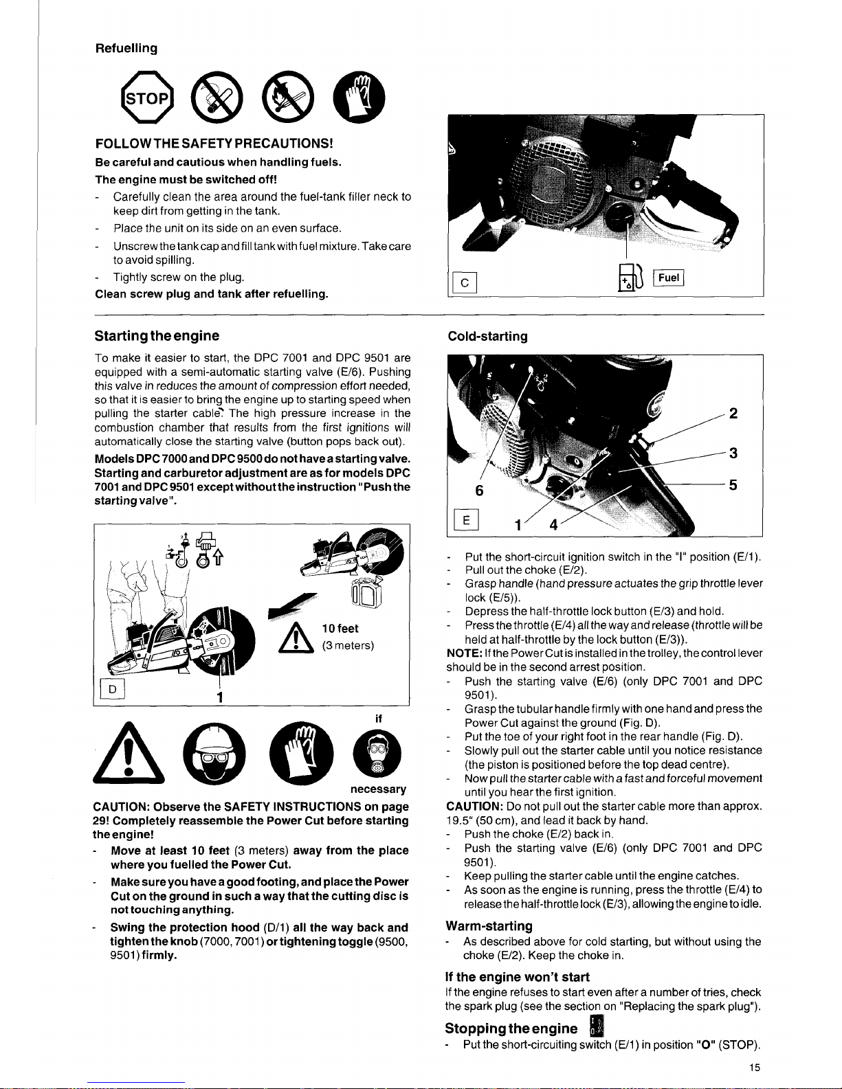
Refuelling
FOLLOW
THE
SAFETY
PRECAUTIONS!
Be careful and cautious when handling fuels.
The engine must be switched off!
-
Carefully clean the area around the fuel-tank filler neck to
keep dirt from getting in the tank.
Place the unit on its side on an even surface.
Unscrewthetankcapandfill tankwith fuel mixture. Takecare
to avoid spilling.
Tightly screw on the plug.
-
-
-
Clean screw plug and tank after refuelling.
Starting theengine
To make it easier to start, the DPC 7001 and DPC 9501 are
equipped with a semi-automatic starting valve
(E/6).
Pushing
this valve in reduces the amount of compression effort needed,
so
that it is easier to bring the engine up to starting speed when
pulling the starter cable? The high pressure increase in the
combustion chamber that results from the first ignitions will
automatically close the starting valve (button pops back out).
Models DPC 7000and DPC 9500do not haveastarting valve.
Starting and carburetor adjustment are as for models DPC
7001
and DPC9501 except without the instruction "Push the
starting valve".
1-1
I
IUI
I
A@@&
necessary
..._...
CAUTION: Observe the SAFETY INSTRUCTIONS on page
29!
Completely reassemble the Power Cut before starting
theengine!
-
Move at least
10
feet (3 meters) away from the place
where you fuelled the Power Cut.
Make sure you have a good footing, and place the Power
Cut on the ground
in
such a way that the cutting disc is
not touching anything.
Swing the protection hood
(D/I)
all the way back and
tighten the knob (7000,7001) ortightening toggle (9500,
9501) firmly.
-
-
Cold-starting
Put the short-circuit ignition switch in the
"I"
position (E/I).
-
Pull out the choke (E/2).
-
Grasp handle (hand pressure actuates the grip throttle lever
lock
(E/5)).
-
Depress the half-throttle lock button
(E/3)
and hold.
-
Press the throttle
(E/4)
all the way and release (throttle will be
held at half-throttle by the lock button (E/3)).
NOTE: If the Power Cut is installed in the trolley, the control lever
should be in the second arrest position.
-
Push the starting valve
(E/6)
(only DPC 7001 and DPC
9501).
-
Grasp the tubular handle firmly with one hand and press the
Power Cut against the ground (Fig.
D).
-
Put the toe of your right foot in the rear handle (Fig. D).
-
Slowly pull out the starter cable until you notice resistance
(the piston is positioned before the top dead centre).
-
Now pull the starter cable with a fast and forceful movement
until you hear the first ignition.
CAUTION: Do not pull out the starter cable more than approx.
19.5"
(50
cm), and lead it back by hand.
-
-
Push the choke (E/2) back in.
Push the starting valve
(E/6)
(only DPC 7001 and DPC
9501).
Keep pulling the starter cable until the engine catches.
As
soon as the engine is running, press the throttle
(E/4)
to
release the half-throttle lock (E/3), allowing the engine to idle.
As
described above for cold starting, but without using the
choke (E/2). Keep the choke in.
-
-
Warm-starting
-
If the engine
won't
start
If the engine refuses to start even after a number of tries, check
the spark plug (see the section on "Replacing the spark plug").
Stopping theengine
-
Put the short-circuiting switch (E/I) in position
"0"
(STOP).
15
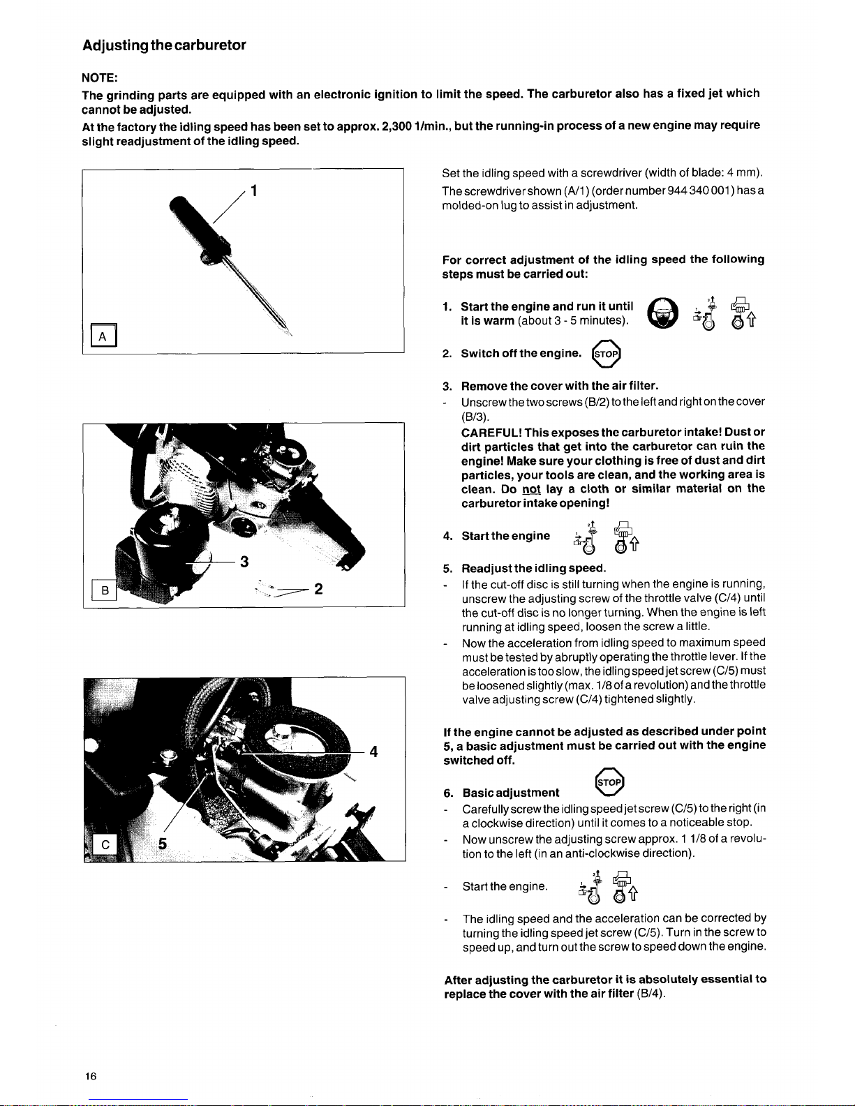
Adjusting
the
carburetor
NOTE:
The grinding parts are equipped with an electronic ignition to limit the speed. The carburetor also has a fixed jet which
cannot be adjusted.
At the factory the idling speed has been set to approx.
2,300
l/min., but the running-in process
of
a new engine may require
slight readjustment
of
the idling speed.
I
Set the idling speed with a screwdriver (width of blade: 4 mm).
Thescrewdrivershown (A/1) (order number 944340001) hasa
molded-on lug to assist in adjustment.
For correct adjustment
of
the idling speed the following
steps must be carried out:
1.
Start the engine and run it until
it
is warm (about 3 - 5 minutes).
2.
Switch off the engine.
STOP
0
3.
Remove the cover with the air filter.
-
Unscrew the two screws
(B/2)
to the left and right on the cover
(B/3).
CAREFUL!
This exposes the carburetor intake! Dust or
dirt particles that get into the carburetor can ruin the
engine! Make sure your clothing is free of dust and dirt
particles, your tools are clean, and the working area is
clean.
Do
not
lay a cloth or similar material on the
carburetor intake opening!
4.
Starttheengine
I,
5.
Readjust the idling speed.
-
If the cut-off disc is still turning when the engine is running,
unscrew the adjusting screw of the throttle valve (C/4) until
the cut-off disc
is
no longer turning. When the engine is left
running at idling speed, loosen the screw a little.
Now the acceleration from idling speed to maximum speed
must be tested byabruptlyoperating the throttle lever.
If
the
acceleration is too slow, the idling speed jet screw (C/5) must
be loosened slightly (max. 1/8 of a revolution) and the throttle
valve adjusting screw (C/4) tightened slightly.
-
If
the engine cannot be adjusted as described under point
5,
a basic adjustment must be carried out with the engine
switched off.
6.
Basicadjustment
-
@
Carefullyscrew the idling speed jet screw (C/5) to the right (in
a clockwise direction) until it comes to a noticeable stop.
Now unscrew the adjusting screw approx. 1 1/8 of a revolution to the left (in an anti-clockwise direction).
-
-
Starttheengine.
+$
?+
-
The idling speed and the acceleration can be corrected by
turning the idling speed jet screw (C/5). Turn in the screw to
speed up, and turn out the screw to speed down the engine.
After adjusting the carburetor
it
is
absolutely essential to
replace the cover with the air filter
(B/4).
16
 Loading...