How it Works
Log In / Sign Up
Buy Points
How it Works
FAQ
Contact Us
Questions and Suggestions
Users
Makita
Loading...
P
PLM4626N
3
PLM4627
PLM4627N
2
PLM4628
PLM4628N
3
PLM4630
PLM4630N
PLM4630N2
3
PLM4631
PLM4631N
2
PLM4631N2
4
PLM4632
PLM4632N
3
PLM4810
5
PLM4811
4
PLM4812
4
PLM4813
4
PLM4814
6
PLM4815
PLM4817
PLM4819
PLM5100
5
PLM5101
5
PLM5102
2
PLM5110
3
PLM5111
2
PLM5112
PLM5113
2
PLM5113N
2
PLM5113N2
3
PLM5114
2
PLM5115
PLM5120
PLM5120N2
2
PLM5121
PLM5121N2
2
PLM5130
2
PLM5130N
4
PLM5600
2
PLM5600N
2
PLM5600N2
2
PM001GZ01
4
PM42
PM4601S
PM48S
PM5101S3
PM7650H
4
PM7650HG
PM7651H
PMD01
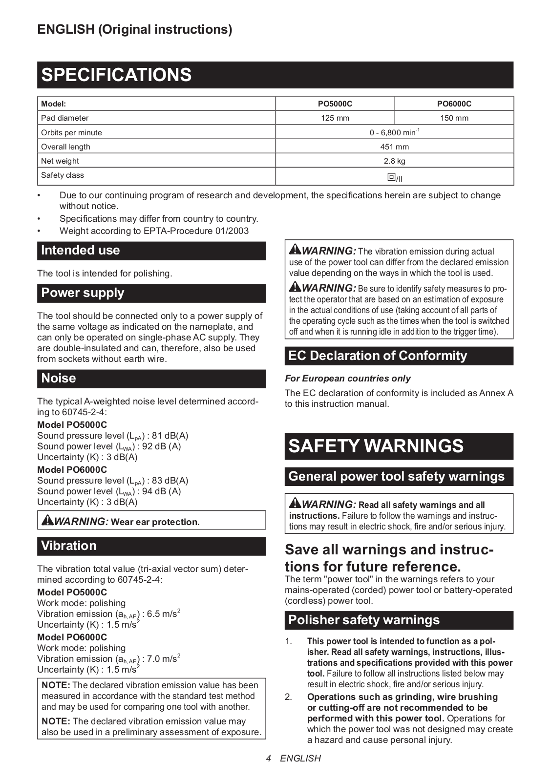
PO5000C
6
PO6000C
6
Poliermaschine 9237CB
Power Cut DPC 7000
Power Cut DPC 7001
Power Cut DPC 9500
Power Cut DPC 9501
PRM0700
4
PS-220 TH
PS-221 TH
PS-222 TH
PS310TH
PS32C
PS34
PS3410
PS-3410 TH
PS34S35
2
PS350
PS400
PS400S40
2
PS401
PS401S40
2
PS420
PS43
PS45
PS460
PS4600S
PS4600S45
PS4600SH
PS4605
PS4605H
PS460D
PS460S45
PS500
PS5000
PS5000D
PS5000DS45
PS5000H
PS5000HD
PS5000S45
PS500D
PS500S45
PS500V
PS5105
PS-6100
PS-6100 H
PS-6400
3
PS-6400H
2
PS-7300
2
PS-7900
2
Loading...
Loading...
Nothing found
PO5000C
Instruction Manual
28 pgs
3.71 Mb
0
Instruction Manual
8 pgs
1.86 Mb
0
Instruction Manual
52 pgs
8.98 Mb
0
Instruction Manual
28 pgs
3.69 Mb
0
Original Instructions Manual
12 pgs
358.06 Kb
0
User Manual
17 pgs
3.49 Mb
0
Table of contents
Loading...
Makita PO5000C User Manual
...
Makita User Manual
Download
Specifications and Main Features
Frequently Asked Questions
User Manual
Download
Page 1
Page 2
Page 3
Page 4
Page 5
Page 6
Page 7
Page 8
Page 9
Page 10
Page 11
Page 12
Page 13
Page 14
Page 15
Page 16
Page 17
Loading...
+
hidden pages
Unhide
You need points to download manuals.
1 point = 1 manual.
You can buy points or you can get point for every manual you upload.
Buy points
Upload your manuals
 Loading...