

Page 1
INSTRUCTION MANUAL
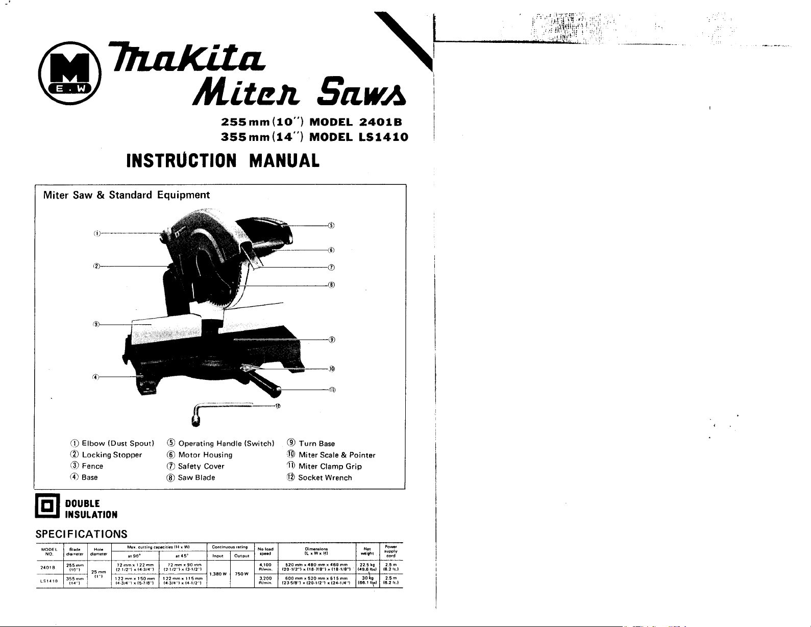
Miter Saw & Standard Equipment
255mm(lO")
355mm(14")
MODEL
MODEL
24016
LS1410
0
@
@
0
DOUBLE
INSULATION
SPEC1
FICATIONS
__
24010
2F:oqm
Elbow (Dust Spout) @ Operating Handle (Switch)
Locking Stopper
Fence
Base
12mmrll2mm
I7
112"l
25
mm
x
14
314
'I
x
14-314"l
15.ll8"l
@
Motor Housing Miter Scale & Pointer
@
Safety Cover
@
Saw Blade
72mmr90mm
12
112"l
x
13-112"l
14
314"l
x
14
112"l
~
1.380
W
750
4,100
Rlmm
W
3.200
Rlmin
8
Turn Base
A
'ii,
Miter Clamp Grip
@
Socket Wrench
520
mm
x
480
120.1/21
600
123
mm
x
118-1/8"1
mm I 520
mm
518"l
x
120-1R"l x 124.114'7 166.1
x
460
x
118-118"1
x
61
I.
mm
22
5
kg
15
149.6
5
mm
30
m
Ibd
18
2
11.1
kg
2
5m
l?*l
18.2
11.1
Page 2
PRELIM
IN
AR
Y I NST
R
UCTl ONS
BEFORE CONNECTING YOUR TOOL
TO A POWER SOURCE
Be sure
you
have
read
all
GENERAL POWER TOOL SAFETY RULES
GENERAL SAFETY PRECAUTIONS
1.
KEEP
GUARDS IN PLACE and in working order.
REMOVE ADJUSTING KEYS AND WRENCHES. Form habit of checking
2.
that keys and adjusting wrenches are removed from
KEEP
3.
WORK AREA CLEAN. Cluttered areas and benches invite accidents.
4. AVOID DANGEROUS ENVIRONMENT. Dont't use power tools in damp
locations. Keep work area well lit.
5.
KEEP
CHILDREN AWAY.
All
visitors should be kept safe distance from work
area.
6.
MAKE WORKSHOP KID PROOF with padlocks, master switches,
starter keys.
7.
DON'T FORCE TOOL.
It
will do the job better and safer at the rate for which it
was designed.
USE RIGHT TOOL. Don't force
8.
tool
or
attachment
for.
9.
WEAR PROPER APPAREL. No loose clothing
parts. Rubber-soled footwear is recommended for best footing.
10.
USE SAFETY GLASSES. Also use face
11. SECURE WORK.
Use clamps
or
a vise
or
to
hold work when practical. It's safer than
using your hand and it frees both hands to operate tool.
12. DON'T OVERREACH. Keep proper footing and balance at all times.
13.
MAINTAIN TOOLS WITH CARE. Keep tools sharp and clean for best and safest
performance. Follow instructions for lubricating and changing accessories.
14.
DISCONNECT TOOLS before servicing; when changing accessories such as blades
or
adjusting guides.
15.
AVOID ACCIDENTAL STARTING. Make sure switch is in off position before
plugging in.
16.
USE RECOMMENDED ACCESSORIES. Consult the owner's manual for recommended accessories. The use of improper accessories may cause hazards.
17. NEVER STAND ON TOOL. Serious injury could occur if the
tool
the cutting
18.
CHECK DAMAGED PARTS. Before further use of the tool, a guard
is accidentally contacted.
that is damaged should be carefully checked to ensure that
and perform its intended function
-
check for alignment of moving parts, binding
of moving parts, breakage of parts, mounting, and any other conditions that may
its
,.
L
affect
repaired
operation. A guard
or
replaced.
or
other part that is damaged should be properly
tool
or
jewelry
to
before turning
do a job
to
get caught in moving
it
on.
or
by removing
it
was not designed
dust maskif cutting operation is dusty.
tool
is
tipped
or
other part
it
will operate properly
or
to
see
wet
or
Your electric tool is precision built and manufactured
performance, long
VOLTAGE WARNING : Before connecting the tool
sure the voltage
with voltage greater than that specified for
well as damage to the tool.
voltage
less
tool
life, and your safety, follow these instructions carefully.
supplied
than the nameplate rating is harmful to the motor.
is
the
same as that specified on the nameplate of the tool. A power source
If
in doubt,
the
DO
NOT PLUG IN THE TOOL. Using a power source with
Precautions Before Use
A. Before plugging in the miter saw,
Check Item Checkpoint
Is
the saw blade installed correctly?
Is
the saw blade tip contacting the turn base when the blade
Does
the safety cover operate smoothly when you raise and
lower the head with the operating handle?
Is
the miter clamp grip tightened firmly?
B.
Set the miter saw on a level bench, sturdy stand
in
just one spot, fasten
obtain a steady base for safe, sure cutting action.
C.
These miter saws are equipped with a locking stopper which is used to keep the head
in
the lowered position. To release from the hold-down position, lower the operation
handle slightly and turn the lever on the locking stopper
lock the head in the hold-down position, lower the operation handle fully and turn the
lever
on the stopper
HOW
TO
USE
YOUR
it
securely by means
to
the hold position.
MAKITA MITER SAW
use
to
satisfy the highest standards.
to
a power source (receptacle, outlet, etc.1
tool can result in SERIOUS INJURY to the user - as
<.
this checklist:
is
fully lowered?
or
table.
If
you intend to use the tool
of
bolts
in
the
four
mounting feet. Always
to
the release position.
For
maximum
be
(2)
(3)
(4)
(5)
To
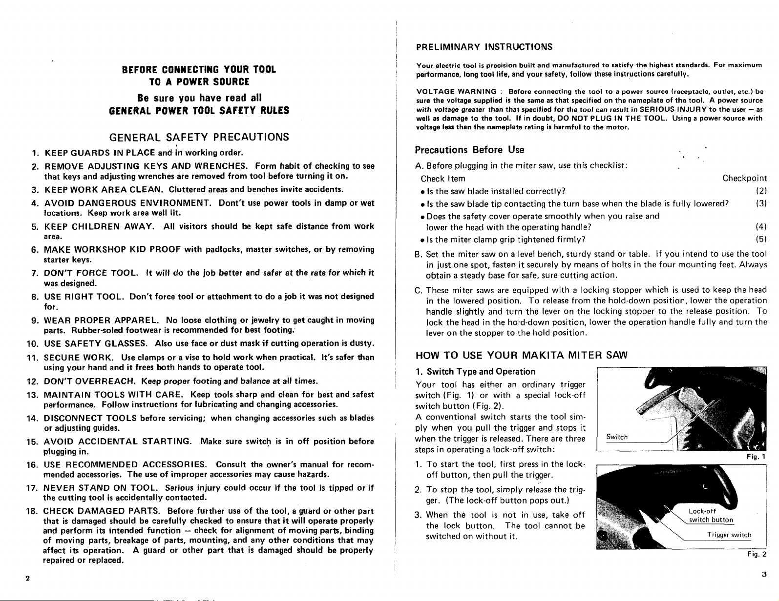
1. Switch Type and Operation
Your
tool
has either an ordinary trigger
switch (Fig.
switch button (Fig.
A conventional switch starts the
ply when you pull the trigger and stops it
when the trigger is released. There are three
steps in operating a
1.
To start the tool, first press
off
if
2.
To
ger. (The
3.
When the
the lock button. The
switched on without
1)
or
with a special lock-off
2).
tool
sim-
lock-off
button, then pull the trigger.
stop the tool, simply release the trig-
lock-off
tool
is
switch:
in
the lock-
button pops out.)
not in use, take
tool
cannot be
it.
off
Fig.
Fig.
1
2
3
Page 3

2.
Installing Saw Blade
lock
Press the shaft
wrench provided
which serves
Then remove the outer flange and install
the saw blade on the arbor shaft inside the
safety cover.
Model 2401B is equipped with an addaptor
ring
(16)
to install a Makita blade. Without the ring,
there is a
3.
Adjusting Vertical Position of Blade
The miter saw is factory-adjusted with a
standard blade cutting depth for a 255mm
(10") saw blade (355mm (14") saw blade
for Model LS1410). Thus,
NOT USING A STANDARD SAW BLADE,
loosen the hex nut on the end
housing and use a minus escrewdriver
turn the cutting depth adjustment bolt to
the right. Adjust
ing handle
there will be a distance
(4-13/16") (about 160mm (6-5/16") for
Model LS1410 from the front face
guide fence (guide rule)
the front edge
(See diagram at right.) This will produce
the correct depth adjustment. Then tighten
the hex. nut.
4.
Safety Cover (Prevents Contact with Blade)
The see-through safety cover (lower blade
guard) raises as the work is contacted and
cutting begins, and
position when cutting is completed. Never
lock the guard at a fixed position. Always
use the guard in the freely telescoping condition for your personal safety. Any irregular operation of the safety guard should be
corrected promptly. Never use the miter
saw with a faulty guard.
*If
the see-through guard becomes dirty
and/or work may not be easily visible, clean it
ALWAYS UNPLUG
4
to
for a 1"
5/8"
arbor hole.
is
in
of
and use the socket
to
loosen the hex bolt
hold the saw blade in place.
arbor hole. Use this ring
IF
YOU ARE
of
the gear
to
so
that when the operat-
the fully lowered position
of
about 122mm
of
the
to
the point where
the blade enters the kerf.
it
returns to its original
or
THE
TOOL before you perform any cleaning.
Fig.
Fig.
Fig.
cover
__
!
Fig.
sawdust adheres in such a way that the blade
off
carefully with a damp cloth.
5.
Miter Angle Setting
The saw blade should be in the fully raised
position before you change the miter angle.
Release the miter clamp grip by turning
one-half a turn
wise), then push the grip in the direction
the desired miter angle. Set the pointer to
the desired graduation on the calibrated
scale, then tighten the grip to the right
(clockwise).
3
6.
When Cutting 2 by
For
Model 2401
Cuts
of
45
long as the material is not positioned vertically.
To
insert a piece
right.
4
7.
Alignment
This Makita miter Saw was carefully adjusted and aligned at the factory, but rough handling during shipment may have affected the alignment.
properly, perform the following.
5
6
*When Slightly Misaligned (Adjusting Pointer)
Loosen the miter clamp grip and place a square
guide fence and saw blade
you notice that the pointer on the miter angle indicator is not at zero on the miter scale,
gently tighten the miter clamp grip and then loosen the two pan head screws holding the
miter angle indicator plate. Adjust
two screws
*When Seriously Misaligned (Adjusting Fence)
After zeroing the miter pointer
grip, loosen the
it will be square in relation
triangular rule against the saw blade and adjusting the fence
the work is absolutely flush with the square
bolts and fasten the fence securely. Failure to fasten securely will cduse,the guide fence
to
move when a workpiece
accuracy will be compromised.
to
the left (counterclock.
of
4
(1-5/8" x 3-1/2"):
B
degrees can be done as usual as
cut vertically positioned material,
of
stock in between as shown
so
as to square the blade to the fence. When this
so
that the pointer will be at zero; then retighten the
to
fasten the plate in place.
(as
shown above) and carefully tightening the miter clamp
four
hex bolts holding the guide fence and reposition the fence
to
the saw blade.
is
pressed up against it by powerful vise action, and thus
--
I
---
I'
I
I
I
I
I
I
I
I
-J
1~5/8"
I
L
Insert
stock
(12
If
your miter saw
or
triangular rule against the side
This can be done by placing
so
that the side contacting
or
rule. Then, carefully replace the hex
Miter
(41
mm)
measuring
mm)
in thickness.
is
scale
Fig.
Fig.
not aligned
of
the
is
done and
so
that
a
square
or
5
Page 4

8.
Tips on Cutting
tool
This
three seconds
safety feature can also be used
light aluminum or plastics where special shapes are required, or
where only a little stock is cut off. In this case, the saw blade is retracted after the blade
stops, and the
a cleaner - as well as safer - cut is p'ossible.
"Always keep the table top clear
safe, clean surface.
9.
Removing Saw Blade
Depressed shaft lock as shown in
shaft/blade. Next, as seen in
socket wrench provided
wise) the hex bolt holding the blade in
place. The remove the bolt and outer
flange. The blade can thus be taken
from the safety cover.
is equipped with an electric safety brake which stops the saw blade within
from
the moment you release the switch
to
advantage, for example, in cutting certain materials like
cut
end will not be contacted by a spinning blade as in a regular saw.
of
chips, small pieces and
0
to
lock
0,
use the
to
loosen (clock-
I
out
Shaft
0
lock
in
the operating handle. This
in
so
on in order
edge cuts
in
to
maintain a
/
wood
Thus,
fig.
11.
Saw Blade
oil
Apply
chips will adhere and the cutting edges will deteriorate. Apply
center
of
with carbide-tipped blades.
12.
Maintenance
Carbon Brushes
Replace carbon brushes when they wear
down
will occur. Both brushes should be
changed
Oiling
Clean the
Apply
13.
Attaching Optional Dust Bag
9
Although sawdust ejection can be directed
at will by means
the dust bag provided makes collection
complete and cutting operations.
To attach the dust bag,
elbow and turn to the left
it
releases
for
Aluminum Applications
to
the miter saw blade
the blade; centrifugal force will distribute it
(No.
(For
Model
2401B
255-4A) for aluminum cutting, since without
out
to
%
to
about 6 mm
at
the same time.
tool
thoroughly after use.
oil
to
all sliding surfaces, the base and saw blade as a rust inhibitor.
to
the right.
(1/4")
of
the elbow, the use
or sparking
fit
it
to
lock in place;
1
of
onto the
only)
oil
near the arbor at the
the tips.
No
oil
it
is required
Fig.
1
0
10.
Factory-Adjusted Lock Nut
The hex lock nut holding together the gear
housing and arm has been factory-adjusted
to assure smooth arm action up and down
and to guarantee precise cutting.
temper with
Should looseness develop at the housing
and arm connection, perform the following
adjustment. Work the arm vertically while
tightening the hex lock nut: the best posi-
to
tion
motor body weight is obvious.
If
the nut is too
hard
to
special type that does not remove in the usual manner, and
tightened or replaced with other types.
6
it.
fasten the nut is just before the
loose,
the cutting accuracy
work the arm up and down easily. Note that this is a
Do
not
will
be affected;
if
it
is
too
tight,
self
locking nut; it
so
it
should not be over-
it
will be
Fig.
Fig.
10
When the bag is about half
lightly
so
as
.to
remove particles adhering
full,
just unzip the fastener below and empty
to
the insides which might hamper collection.
it,
slapping it
ACCESSORIES
Dust Bag
11
is
a
Part
No.
166004-3
Page 5

/
Saw
Blades
Chisel tooth combination saw blade
For
rip and cross-cut work.
Most freauentlv used
NO.
DM
lmml
-
7
__-
2551
10'
260 110.114"1
I
255-7
260
for
general carpentry.
di:Y&l
,r:h
2511,,1
36
Part
No.
7214074
721411-3
Far
24018
Model
Miter saw blade
Carbide-tipped saw blade
*
Combination saw blade
Cross-cut
saw blade
No.
255
N-q.
255
255-4
255
-4A
Faster, smoother, longer sawing
without blade sharpening cuts wood, dry wall,
plastics, hard wood, etc.
NO
-
__~_
*255-
11
155
="A_.
.355-11
NO
255-1. 2551
260
-
1
NO
For smooth cutting of wood.
-
4
-
4A
For smooth cutting of aluminum.
2511"l
2551
10''
Dm
lmml
~
2551
lo
~__
~__
355114
Dle.
lmml
IO' 1 2511,,1
260 110-114")
Dm
Imml
I
d,zEml
~-
I
d,:T&l
d,:y&l
100
,t:h
-
-
2511'1 72 7214121
70 7214066
100
,ye:h
57
,::h
7214040
1
7214058
1
2401e
Per1
No
For
-__
24018
721611 5 LS1410
Part
No.
For
721401-6
24018
7214090
Far
Pert
No
Model
Model
Modal
i
,
-
Combination saw blade
For
NO.
Dia.
lmml
di~~~ml
lf:;
Part
No.
Model
€kct&i&-,Ltd.
Anjo, Aichi, Japan PRINTED IN JAPAN
1979-5-2,000
N
.
 Loading...