

Makita LS1216, LS1216F, LS1216FL User manual
GB
LS1216
LS1216L
LS1216F
LS1216FL
Slide Compound Miter Saw Instruction Manual
F
Scie à Onglet Radiale Manuel d’instructions
D
Kapp- und Gehrungssäge Betriebsanleitung
I
Sega combinata a slitta Istruzioni per l’uso
NL
Schuifbare afkortverstekzaag Gebruiksaanwijzing
E
Sierra de Inglete Telescópica Manual de instrucciones
P
Serra de Esquadria c/ Braço Telescópico Manual de instruções
DK
Afkorter-geringssav Brugsanvisning
∆ισκοπρίονο σύνθετησ λοξοτοµήσ µήκουσ
GR
ολίσθησησ
Οδηγίεσ χρήσεωσ
12
5
6
4
7
8
9
2
2
2
4
3
3
1
009483 010593
34
5
009485 009486
009488
6
2
001538
7
22
10
21
20
19
14
17
16
18
12
13
14
15
11
10
009496
8
910
11 12
009737 009736
009487 009517
009518
3
13 14
23
24
24
27
26
25
33
32
31
28
29
30
23
29
30
28
11
10
009489 010322
15 16
17 18
19 20
4
009513 009496
009886 009491
010533 009492
37
35
38
3
21 22
A
B
34
35
34
36
20
1
009493 009494
23 24
25 26
012597 009495
009483
012591
5
41 41
40
5
38
42
5
43
44
38
42
5
43
44
45
38
37
36
3
2
m
39
40
38
1
28
27 29
30 31
012592 013265
012594
009500
012593
009483 009497
32 33
6
46
47
48
35
2
39
40
41 41
40
5
2
009500
34 36
37 38
009498 009925
012680
49
2
42
5
45
44
43
009501
52
51
39 40
50
49
53
010592006793
7
52
49
55
54
56
23
41 42
010591 001549
43 44
45 46
009508 010594
009611 009502
59
62
57
58
63
60
61
64
47 48
8
65
60
009606 005232

66
63
49 50
11
10
009607 009503
51 52
53 54
009496 009504
009505 001555
(1) (2) (3) (4)
70
55 56
71
001556 001557
38°
70
(1)
(2)
52°
67
45°
45°
69
(1)
(2)
71
(1)
(2)
45°
45°
68
(2)
(1)
(2)
(1)
(4)
(3)
9
72
13
73
74
13
75
80
83
81
82
135mm
106mm
116mm 180mm
80mm
115 - 120mm
83
84
85 86
87
88
57 58
009521
009522
18
76
59 60
009520
61
18
77
78
79
78
009523
010046
62 63
10
001563 010357
57
89
90
88
1
91
92
63
27
27
23
93
94
24
23
64 65
010356 009483
66 67
68 69
009506 009509
009525 009512
70 71
009511 001819
91
5
95
11
93
27
27
25
96
97
98
90
101
99
100
101
102
99
103
72 73
009490 009608
89
74 75
76 77
78 79
12
009526 009527
009609 009610
001145 009516

Symbols
The following show the symbols used for the equipment. Be sure that you understand their meaning before use.
Symboles
Nous donnons ci-dessous les symboles utilisés pour l’outil. Assurez-vous que vous en avez bien compris la
signification avant d’utiliser l’outil.
Symbole
Die folgenden Symbole werden für die Maschine verwendet. Machen Sie sich vor der Benutzung unbedingt mit ihrer
Bedeutung vertraut.
Simboli
Per questo utensile vengono usati i simboli seguenti. Bisogna capire il loro significato prima di usare l’utensile.
Symbolen
Voor dit gereedschap worden de volgende symbolen gebruikt. Zorg ervoor dat u de betekenis van deze symbolen
begrijpt alvorens het gereedschap te gebruiken.
Símbolos
A continuación se muestran los símbolos utilizados con esta herramienta. Asegúrese de que entiende su significado
antes de usarla.
Símbolos
O seguinte mostra os símbolos utilizados para a ferramenta. Certifique-se de que compreende o seu significado antes
da utilização.
Symboler
Nedenstående symboler er anvendt i forbindelse med denne maskine. Vær sikker på, at De har forstået symbolernes
betydning, før maskinen anvendes.
Σύµβολα
Τα ακλουθα δείχνουν τα σύμβολα που χρησιμοποιούνται για το μηχάνημα. Βεβαιωθείτε τι καταλαβαίνετε
τη σημασία τους πριν απ τη χρήση.
END210-6
• Read instruction manual. • Lea el manual de instrucciones.
• Lire le mode d’emploi. • Leia o manual de instruções.
• Bitte Bedienungsanleitung lesen. • Læs brugsanvisningen.
• Leggete il manuale di istruzioni. • Διαβάστε τις οδηγίες χρήσης.
• Lees de gebruiksaanwijzing.
• DOUBLE INSULATION • DOBLE AISLAMIENTO
• DOUBLE ISOLATION • DUPLO ISOLAMENTO
• DOPPELT SCHUTZISOLIERT • DOBBELT ISOLERET
• DOPPIO ISOLAMENTO • ΔΙΠΛΗ ΜΟΝΩΣΗ
• DUBBELE ISOLATIE
• To avoid injury from flying debris, keep holding the saw head down, after making cuts, until the
blade has come to a complete stop.
• Pour éviter les blessures causées par les objets projetés, maintenez la tête de la scie en position basse une fois la coupe terminée, jusqu’à ce que la lame soit complètement arrêtée.
• Um Verletzungen durch herausgeschleuderte Teile zu vermeiden, halten Sie den Sägekopf
nach Ausführung von Schnitten abgesenkt, bis das Sägeblatt völlig zum Stillstand gekommen
ist.
• Per evitare lesioni dalle schegge volanti, dopo aver eseguito il taglio tenere abbassata la testa
sega finché la lama non si è arrestata completamente.
• Om verwonding door weggeslingerd zaagafval te voorkomen, dient u na het voltooien van een
snede de zaagkop omlaag te houden totdat het zaagblad volledig tot stilstand is gekomen.
• Para evitar sufrir heridas a causa de restos que salen despedidos, siga sujetando la cabeza de
la sierra hacia abajo, al terminar los cortes, hasta que el disco se haya parado completamente.
• Para evitar danos causados por aparas que saltem, mantenha a cabeça da serra para baixo,
depois de terminar os cortes, até que a lâmina esteja completamente parada.
• For at undgå at komme til skade på grund af flyvende affald, skal man holde savhovedet nede
efter skæring, indtil savklingen står helt stille.
• Για να αποφύγετε τραυματισμ απ ιπτάμενα τεμαχίδια, κρατάτε το πρινι με το
κεφάλι προς τα κάτω, αφού κάνετε κοπές, μέχρι η λάμα να σταματήσει τελείως.
13
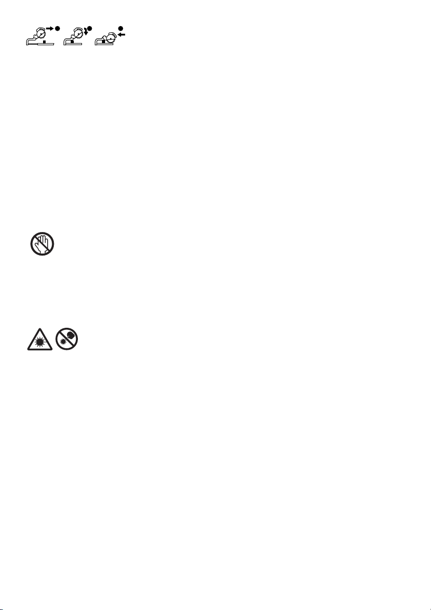
• When performing slide cut, first pull carriage fully and press down handle, then push carriage
1
2
3
toward the guide fence.
• Lorsque vous effectuez une coupe en glissière, tirez d’abord complètement le chariot et abaissez la poignée, puis poussez le chariot vers le guide.
• Ziehen Sie den Schlitten zur Ausführung von Schiebeschnitten zunächst ganz vor, drücken Sie
den Griff nach unten, und schieben Sie dann den Schlitten zum Gehrungsanschlag.
• Per eseguire un taglio di scorrimento, tirare prima completamente il carrello, premere giù il
manico e spingere poi il carrello verso la guida pezzo.
• Bij drukkend (glijdend) zagen, dient u eerst de slede volledig naar u toe te trekken en het handvat omlaag te drukken. Duw daarna de slede naar de geleider toe.
• Cuando haga cortes de deslizamiento, primero tire del carro completamente y presione hacia
abajo la empuñadura, después empuje el carro hacia la guía lateral.
• Quando executa corte corrediço, puxe primeiro o carro completamente e empurre a pega para
baixo e em seguida empurre o carro na direcção da placa guia.
• Når man udfører savning ved gliden, skal man først trække slæden helt og trykke håndtaget
ned og derefter trykke slæden mod anslaget.
• Οταν εκτελείτε ολισθητική κοπή, πρώτα τραβήχτε την κινητή βάση πλήρως και
πατήστε την λαβή κάτω, μετά σπρώχτε την κινητή βάση προς τον φράχτη οδηγ.
• Do not place hand or fingers close to the blade.
• Ne pas placer les mains ou les doigts près de la lame.
• Halten Sie Hände oder Finger vom Sägeblatt fern.
• Non avvicinare le mani o le dita alla lama.
• Kom met uw handen of vingers niet te dicht bij het zaagblad.
• No ponga la mano ni los dedos cerca del disco.
• Não coloque a sua mão ou dedos perto da lâmina.
• Hold hænder og fingre på god afstand af klingen.
• Μη βάζετε το χέρι ή τα δάκτυλα κοντά στην λάμα.
14
• Never look into the laser beam. Direct laser beam may injure your eyes.
• Ne jamais regarder directement la source du faisceau laser. L’exposition directe au faisceau
laser comporte un risque de blessure aux yeux.
• Blicken Sie auf keinen Fall in den Laserstrahl. Der direkte Laserstrahl kann Ihre Augen verletzen.
• Mai guardare direttamente il raggio laser. Il raggio laser può danneggiare gli occhi.
• Kijk nooit in de laserstraal. Een directe laserstraal kan oogletsel veroorzaken.
• No mire nunca directamente al rayo láser. El rayo láser directo puede dañar sus ojos.
• Nunca olhe para o raio laser. Se olhar directamente para o raio laser pode ferir os seus olhos.
• Se aldrig ind i laserstrålen. Direkte udsættelse for laserstråling kan skade dit syn.
• Ποτέ μη κυττάτε απευθείας την ακτίνα λέιζερ. Η απευθείας ακτίνα λέιζερ μπορεί να
προκαλέσει τραυματισμ στα μάτια σας.

• Only for EU countries
Do not dispose of electric equipment together with household waste material!
In observance of European Directive 2002/96/EC on waste electric and electronic equipment and its
implementation in accordance with national law, electric equipment that have reached the end of their
life must be collected separately and returned to an environmentally compatible recycling facility.
• Pour les pays européens uniquement
Ne pas jeter les équipements électriques dans les ordures ménagères !
Conformément à la directive européenne 2002/96/EG relative aux déchets d’équipements électriques
ou électroniques (DEEE), et à sa transposition dans la législation nationale, les équipements électriques doivent être collectés à part et être soumis à un recyclage respectueux de l’environnement.
• Nur für EU-Länder
Werfen Sie Elektrogeräte nicht in den Hausmüll!
Gemäß Europäischer Richtlinie 2002/96/EG über Elektro- und Elektronik-Altgeräte und Umsetzung in
nationales Recht müssen verbrauchte Elektrogeräte getrennt gesammelt und einer umweltgerechten
Wiederverwertung zugeführt werden.
• Solo per Paesi UE
Non gettare le apparecchiature elettriche tra i rifiuti domestici.
Secondo la Direttiva Europea 2002/96/CE sui rifiuti di apparecchiature elettriche ed elettroniche e la
sua attuazione in conformità alle norme nazionali, le apparecchiature elettriche esauste devono
essere raccolte separatamente, al fine di essere riciclate in modo eco-compatibile.
• Alleen voor EU-landen
Geef elektrische apparaten niet met het huisvuil mee!
Volgens de Europese richtlijn 2002/96/EG inzake oude elektrische en elektronische apparaten en de
toepassing daarvan binnen de nationale wetgeving, dient gebruikt elektrische apparaten gescheiden te
worden ingezameld en te worden afgevoerd naar een recycle bedrijf dat voldoet aan de geldende
milieu-eisen.
• Sólo para países de la Unión Europea
¡No deseche los aparatos eléctricos junto con los residuos domésticos!
De conformidad con la Directiva Europea 2002/96/CE sobre residuos de aparatos eléctricos y elec-
trónicos y su aplicación de acuerdo con la legislación nacional, los aparatos eléctricos cuya vida útil
haya llegado a su fin se deberán recoger por separado y trasladar a una planta de reciclaje que cumpla
con las exigencias ecológicas.
• Apenas para países da UE
Não deite ferramentas eléctricas no lixo doméstico!
De acordo com a directiva europeia 2002/96/CE sobre ferramentas eléctricas e electrónicas usadas e
a sua aplicação para as leis nacionais, as ferramentas eléctricas usadas deven ser recolhidas em separado e encaminhadas a uma instalação de reciclagem dos materiais ecológicos.
• Kun for EU-lande
Elværktøj må ikke bortskaffes som almindeligt affald!
I henhold til det europæiske direktiv 2002/96/EF om bortskaffelse af elektriske og elektroniske produk-
ter og gældende national lovgivning skal brugt elværktøj indsamles separat og returneres til miljøgodkendt genindvinding.
• Μνο για τις χώρες της ΕΕ
Μη πετάτε τα είδη ηλεκτρικού εξοπλισμού μαζί με τα οικιακά απορρίμματα.
Σε τήρηση της Eυρωπαϊκής Oδηγίας 2002/96/ΕΚ, περί απορριμμάτων ειδών ηλεκτρικού και
ηλεκτρονικού εξοπλισμού και την εφαρμογή της σύμφωνα με την εθνική νομοθεσία, τα είδη
ηλεκτρικού εξοπλισμού που έχουν φθάσει στο τέλος της ζωής τους πρέπει να συλλέγονται
ξεχωριστά και να επιστρέφονται σε μιά περιβαλλοντικά συμβατή εγκατάσταση ανακύκλωσης.
15

ENGLISH (Original instructions)
1 Stopper pin
2Hex bolt(s)
3 Blade guard
4 Kerf board
5 Saw blade
6 Blade teeth
7 Left bevel cut
8 Straight cut
9 Right bevel cut
10 Lock lever
11 Locking screw
12 Adjusting bolt
13 Turn base
14 Stopper lever
15 Slide pipe
16 Top surface of turn base
17 Periphery of blade
18 Guide fence
19 Stopper arm
20 Adjusting screw
21 Grip
22 Cam
23 Levers
24 Latch lever
25 Scale plate
26 Release button
27 Pointer
28 Lock-off button
29 Switch trigger
30 Hole for padlock
31 Switch for light
32 Light
33 Switch for laser
34 Wrench holder
35 Hex wrench
36 Socket wrench
Explanation of general view
37 Center cover
38 Hex socket bolt
39 Shaft lock
40 Blade case
41 Arrow
42 Outer flange
43 Inner flange
44 Spindle
45 Ring
46 Fastener
47 Dust bag
48 Dust nozzle
49 Dust box
50 Cover
51 Button
52 Cylinder section
53 Sawdust
54 Support
55 Turn base
56 Clamping screws
57 Upper fence
58 Lower fence
59 Red indicating area
60 Vise knob
61 Vise arm
62 Vise rod
63 Screw
64 Vise plate
65 Vise nut
66 Holder
67 52/38° type crown molding
68 45° type crown molding
69 45° type cove molding
70 Inside corner
71 Outside corner
72 Crown molding stopper L
(Optional accessory)
73 Crown molding stopper R
(Optional accessory)
74 Crown molding stopper L
75 Crown molding stopper R
76 Crown molding
77 Vise
78 Spacer block
79 Aluminum extrusion
80 Over 15 mm
81 Over 290 mm
82 Over 340 mm
83 Hole
84 Cut grooves with blade
85 Screws (two each side)
86 Lower fence
87 Base
88 Platform
89 Vertical vise
90 Workpiece
91 Triangular rule
92 Miter scale
93 Bevel scale plate
94 0° Angle adjusting bolt
95 Top surface of turn table
96 Left 45° bevel angle adjusting
bolt
97 Right 45° bevel angle adjusting
bolt
98 Laser line
99 Screwdriver
100 Screw (one piece only)
101 Lens for the laser light
102 Limit mark
103 Brush holder cap
SPECIFICATIONS
Model LS1216/LS1216L/LS1216F/LS1216FL
Blade diameter .................................................................................................................................................... 305 mm
Blade body thickness ........................................................................................................................... 1.6 mm – 2.4 mm
Hole diameter.....................................................European countries: 30 mm, other than European countries: 25.4 mm
Max. Miter angle.................................................................................................................................. Left 52°, Right 60°
Max. Bevel angle..................................................................................................................................Left and Right 45°
Max. cutting capacities (H xW)
Bevel angle
87 mm × 382 mm
102 mm × 363 mm
87 mm × 268 mm
102 mm × 255 mm
44 mm × 382 mm
54 mm × 363 mm
44 mm × 268 mm
54 mm × 255 mm
0°
45° (left and
right)
Miter angle
Thickness of wood
facing on guide
fence for increased
height of cut
Thickness of wood
facing on guide
fence for increased
height of cut
45° (left) 0° 45° (right)
59 mm × 382 mm
69 mm × 363 mm
35 mm 78 mm × 290 mm 115 mm × 300 mm 61 mm × 290 mm
60 mm – 120 mm × 250 mm –
59 mm × 268 mm
69 mm × 255 mm
30 mm – 115 mm × 202 mm –
45 mm – 120 mm × 172 mm –
16

52° (left and
right)
60° (right)
Thickness of wood
facing on guide
fence for increased
height of cut
Thickness of wood
facing on guide
fence for increased
height of cut
–
–
25 mm – 115 mm × 178 mm –
35 mm – 120 mm × 155 mm –
–
–
25 mm – 115 mm × 140 mm –
35 mm – 120 mm × 122 mm –
87 mm × 233 mm
102 mm × 220 mm
87 mm × 185 mm
102 mm × 178 mm
–
–
–
–
Special Max. Cutting capacities
Crown molding 45° type (with Crown molding stopper used) 203 mm
Base board (H) (with Horizontal vise used) 165 mm
Special Max Width Cutting Capacities (with 38 mm (1-1/2”) thick platform used)
Bevel angle Miter angle Max. cutting
0°
Refer to OPERATION for the cutting procedure.
No load speed (min
Laser Type (LS1216L, LS1216FL only)..................................................Red Laser 650 nm, <1.6 mW (Laser Class 2M)
Dimensions (L x W x H) .....................................................................................................806 mm x 640 mm x 721 mm
Net weight
For all countries other than European countries
LS1216 .............................................................................................................................................................. 26.3 kg
LS1216L/LS1216F............................................................................................................................................. 26.4 kg
LS1216FL .......................................................................................................................................................... 26.5 kg
For European countries
LS1216 .............................................................................................................................................................. 26.5 kg
LS1216L/LS1216F............................................................................................................................................. 26.6 kg
LS1216FL .......................................................................................................................................................... 26.7 kg
Safety class .............................................................................................................................................................. /II
• Due to our continuing program of research and development, the specifications herein are subject to change
without notice.
• Specifications may differ from country to country.
• Weight according to EPTA-Procedure 01/2003
Intended use
The tool is intended for accurate straight and miter cutting in wood. With appropriate saw blades, aluminum can
–1
) ............................................................................................................................................ 3,200
ENE006-1
also be sawed.
Power supply
The tool should be connected only to a power supply of
the same voltage as indicated on the nameplate, and can
only be operated on single-phase AC supply. They are
double-insulated and can, therefore, also be used from
sockets without earth wire.
ENF002-2
GEA010-1
General Power Tool Safety Warnings
WARNING Read all safety warnings and all
instructions. Failure to follow the warnings and instruc-
tions may result in electric shock, fire and/or serious
injury.
Save all warnings and instructions for future reference.
0° 416 mm
45° (Left and right) 292 mm
ADDITIONAL SAFETY RULES FOR TOOL
1. Wear eye protection.
2. Keep hands out of path of saw blade. Avoid contact with any coasting blade. It can still cause
severe injury.
3. Do not operate saw without guards in place.
Check blade guard for proper closing before
each use. Do not operate saw if blade guard
does not move freely and close instantly. Never
clamp or tie the blade guard into the open position.
4. Do not perform any operation freehand. The
workpiece must be secured firmly against the turn
base and guide fence with the vise during all operations. Never use your hand to secure the workpiece.
5. Never reach around saw blade.
6. Turn off tool and wait for saw blade to stop
before moving workpiece or changing settings.
7. Unplug tool before changing blade or servicing.
8. Always secure all moving portions before carrying the tool.
9. Stopper pin which locks the cutter head down is
for carrying and storage purposes only and not
for any cutting operations.
ENB034-6
17

10. Do not use the tool in the presence of flammable
liquids or gases. The electrical operation of the tool
could create an explosion and fire when exposed to
flammable liquids or gases.
11. Check the blade carefully for cracks or damage
before operation.
Replace cracked or damaged blade immediately.
12. Use only flanges specified for this tool.
13. Be careful not to damage the arbor, flanges
(especially the installing surface) or bolt. Damage to these parts could result in blade breakage.
14. Make sure that the turn base is properly secured
so it will not move during operation.
15. For your safety, remove the chips, small pieces,
etc. from the table top before operation.
16. Avoid cutting nails. Inspect for and remove all
nails from the workpiece before operation.
17. Make sure the shaft lock is released before the
switch is turned on.
18. Be sure that the blade does not contact the turn
base in the lowest position.
19. Hold the handle firmly. Be aware that the saw
moves up or down slightly during start-up and
stopping.
20. Make sure the blade is not contacting the workpiece before the switch is turned on.
21. Before using the tool on an actual workpiece, let
it run for a while. Watch for vibration or wobbling
that could indicate poor installation or a poorly
balanced blade.
22. Wait until the blade attains full speed before cutting.
23. Stop operation immediately if you notice anything abnormal.
24. Do not attempt to lock the trigger in the on position.
25. Be alert at all times, especially during repetitive,
monotonous operations. Don’t be lulled into a
false sense of security. Blades are extremely
unforgiving.
26. Always use accessories recommended in this
manual. Use of improper accessories such as
abrasive wheels may cause an injury.
27. Do not use the saw to cut other than wood, aluminum or similar materials.
28. Connect miter saws to a dust collecting device
when sawing.
29. Select saw blades in relation to the material to
be cut.
30. Take care when slotting.
31. Replace the kerf board when worn.
32. Do not use saw blades manufactured from high
speed steel.
33. Some dust created from operation contains
chemicals known to cause cancer, birth defects
or other reproductive harm. Some examples of
these chemicals are:
• lead from lead-based-painted material and,
• arsenic and chromium from chemically-treated
lumber.
Your risk from these exposures varies, depending on how often you do this type of work. To
reduce your exposure to these chemicals:
work in a well ventilated area and work with
approved safety equipment, such as those
dust masks that are specially designed to filter
out microscopic particles.
34. To reduce the emitted noise, always be sure that
the blade is sharp and clean.
35. The operator is adequately trained in the use,
adjustment and operation of the machine.
36. Use correctly sharpened saw blades. Observe
the maximum speed marked on the saw blade.
37. Refrain from removing any cut-offs or other
parts of the workpiece from the cutting area
whilst the tool is running and the saw head is not
in the rest position.
38. Use only saw blades recommended by the
manufacturer which conform to EN847-1.
39. Wear gloves for handling saw blade (saw blades
shall be carried in a holder wherever practicable)
and rough material.
40. When fitted with laser, no exchange with different type of laser is permitted. Repairs shall only
be carried out correctly.
SAVE THESE INSTRUCTIONS.
INSTALLATION
Bench mounting
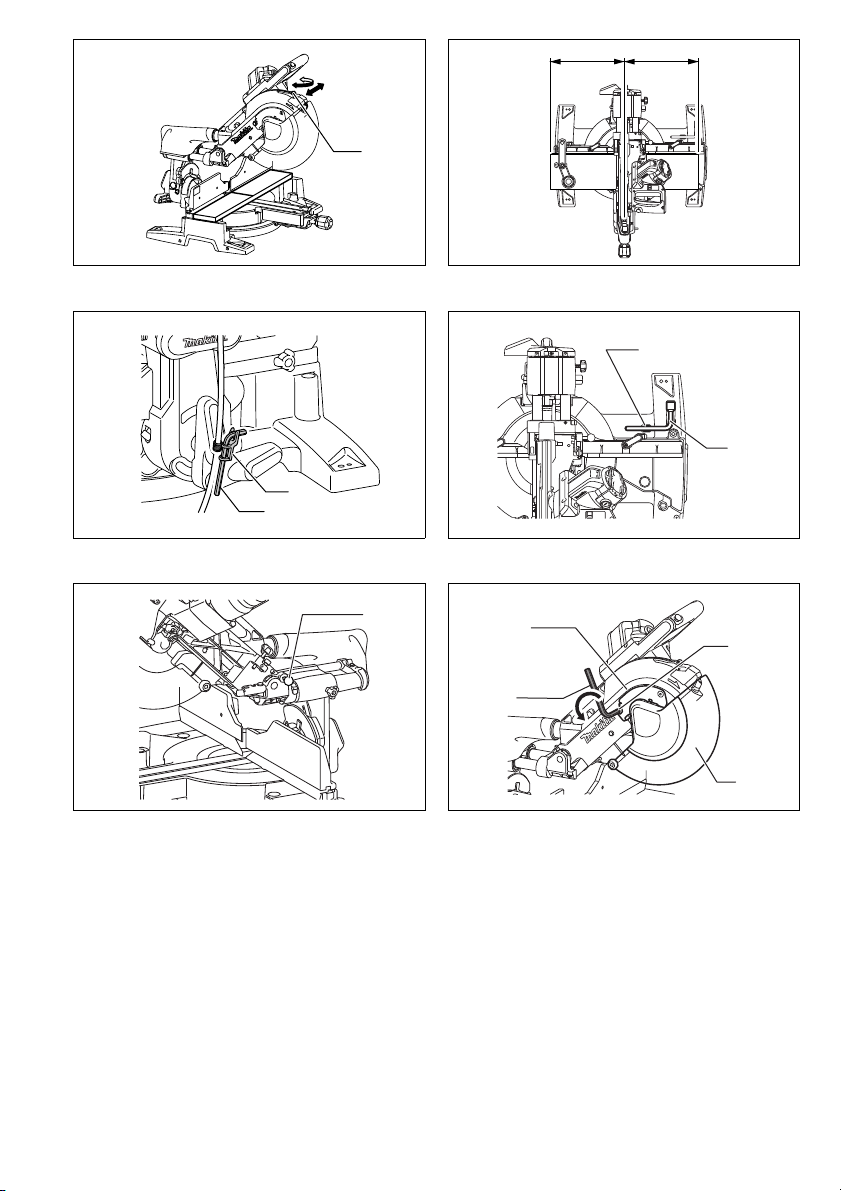
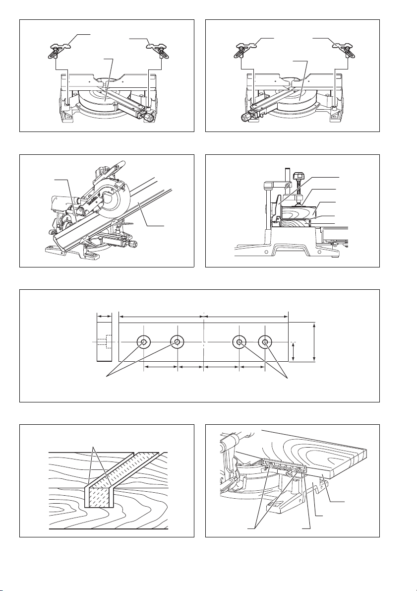
When the tool is shipped, the handle is locked in the lowered position by the stopper pin. Release the stopper pin
by simultaneously applying a slight downward pressure
on the handle and pulling the stopper pin. (Fig. 1)
WARNING:
• Ensure that the tool will not move on the support-
ing surface. Movement of the miter saw on the sup-
porting surface while cutting may result in loss of
control and serious personal injury.
This tool should be bolted with four bolts to a level and
stable surface using the bolt holes provided in the tool’s
base. This will help prevent tipping and possible injury.
(Fig. 2)
FUNCTIONAL DESCRIPTION
WARNING:
•
Always be sure that the tool is switched off and
unplugged before adjusting or checking function on
the tool.
Failure to switch off and unplug the tool may
result in serious personal injury from accidental start-up.
Blade guard (Fig. 3 & 4)
When lowering the handle, the blade guard rises automatically. The blade guard returns to its original position
when the cut is completed and the handle is raised.
WARNING:
• Never defeat or remove the blade guard or the
spring which attaches to the guard. An exposed
blade as a result of defeated guarding may result in
serious personal injury during operation.
In the interest of your personal safety, always maintain
the blade guard in good condition. Any irregular operation of the blade guard should be corrected immediately.
Check to assure spring loaded return action of guard.
WARNING:
• Never use the tool if the blade guard or spring are
damaged, faulty or removed. Operation of the tool
with a damaged, faulty or removed guard may result in
serious personal injury.
18

If the see-through blade guard becomes dirty, or sawdust
adheres to it in such a way that the blade and/or workpiece is no longer easily visible, unplug the saw and
clean the guard carefully with a damp cloth. Do not use
solvents or any petroleum-based cleaners on the plastic
guard because this may cause damage to the guard.
If the blade guard becomes dirty and needs to be
cleaned for proper operation follow the steps below:
With the tool switched off and unplugged, use the supplied socket wrench to loosen the hex bolt holding the
center cover. Loosen the hex bolt by turning it counterclockwise and raise the blade guard and center cover.
With the blade guard so positioned, cleaning can be
more completely and efficiently accomplished. When
cleaning is complete, reverse procedure above and
secure bolt. Do not remove spring holding blade guard. If
guard becomes damaged through age or UV light exposure, contact a Makita service center for a new guard.
DO NOT DEFEAT OR REMOVE GUARD.
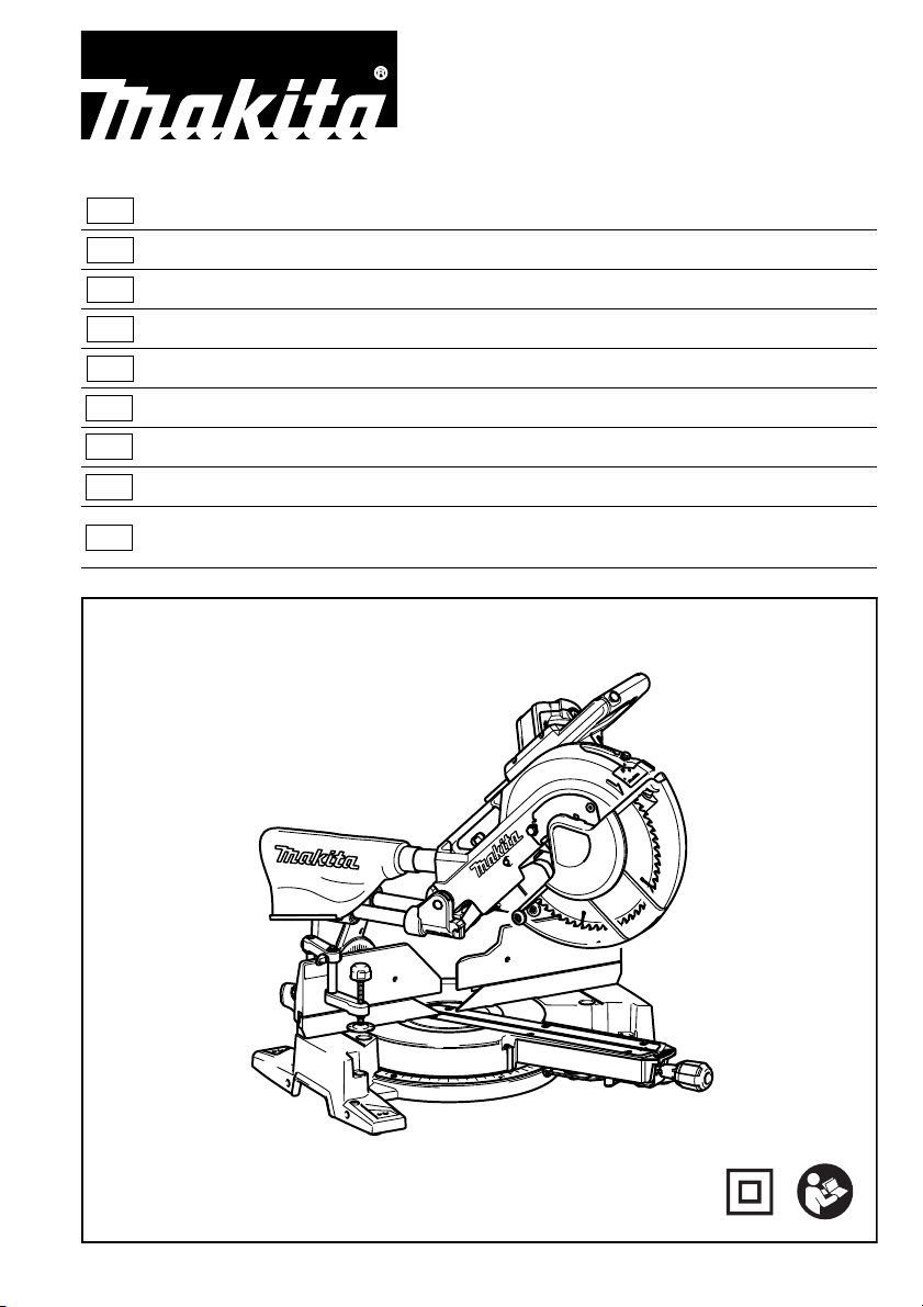
Positioning kerf board (Fig. 5, 6 & 7)
This tool is provided with the kerf boards in the turn base
to minimize tearing on the exit side of a cut. The kerf
boards are factory adjusted so that the saw blade does
not contact the kerf boards. Before use, adjust the kerf
boards as follows:
First, unplug the tool. Loosen all the screws (3 each on
left and right) securing the kerf boards. Re-tighten them
only to the extent that the kerf boards can still be easily
moved by hand. Lower the handle fully and push in the
stopper pin to lock the handle in the lowered position.
Loosen the locking screw counterclockwise which
secures the upper slide poles and also push forward the
lock lever which secures the lower slide poles. Pull the
carriage toward you fully. Adjust the kerf boards so that
the kerf boards just contact the sides of the blade teeth.
Tighten the front screws (do not tighten firmly). Push the
carriage toward the guide fence fully and adjust the kerf
boards so that the kerf boards just contact the sides of
blade teeth. Tighten the rear screws (do not tighten
firmly).
After adjusting the kerf boards, release the stopper pin
and raise the handle. Then tighten all the screws
securely.
NOTICE:
• After setting the bevel angle ensure that the kerf
boards are adjusted properly. Correct adjustment of
the kerf boards will help provide proper support of the
workpiece minimizing workpiece tear out.
Maintaining maximum cutting capacity
(Fig. 8, 9 & 10)
This tool is factory adjusted to provide the maximum cutting capacity for a 305 mm saw blade.
Unplug the tool before any adjustment is attempted.
When installing a new blade, always check the lower limit
position of the blade and if necessary, adjust it as follows:
First, unplug the tool. Lower the stopper lever to position
the saw blade as shown in the figure. Push the carriage
toward the guide fence fully and lower the handle completely. Use the socket wrench to turn the adjusting bolt
until the periphery of the blade extends slightly below the
top surface of the turn base at the point where the front
face of the guide fence meets the top surface of the turn
base.
With the tool unplugged, rotate the blade by hand while
holding the handle all the way down to be sure that the
blade does not contact any part of the lower base. Readjust slightly, if necessary.
After adjustment, always return the stopper lever to the
original position by turning it counterclockwise.
WARNING:
• After installing a new blade and with the tool
unplugged, always be sure that the blade does not
contact any part of the lower base when the handle
is lowered completely. If a blade makes contact with
the base it may cause kickback and result in serious
personal injury.
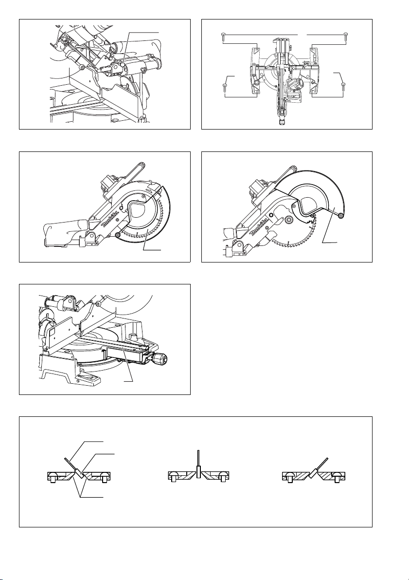
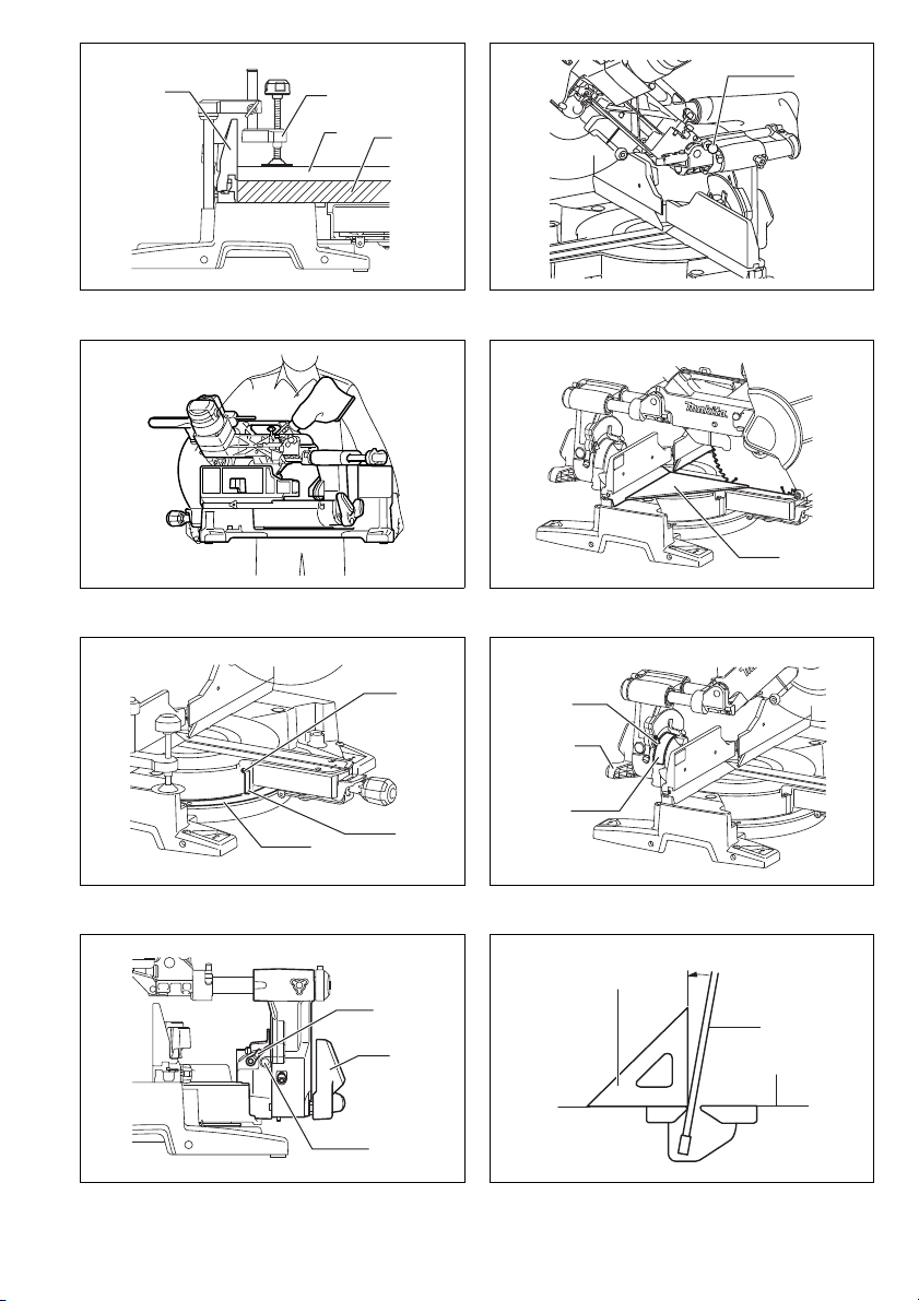
Stopper arm (Fig. 11)
The lower limit position of the blade can be easily
adjusted with the stopper arm. To adjust it, rotate the
stopper arm in the direction of the arrow as shown in the
figure. Adjust the adjusting screw so that the blade stops
at the desired position when lowering the handle fully.
Adjusting the miter angle (Fig. 12)
Push the grip so that the cams engages and turn it clockwise until it stops. Turn the turn base while pressing
down the lock lever. When you have moved the grip to
the position where the pointer points to the desired angle
on the miter scale, turn the grip 90° counterclockwise to
lock the turn base.
CAUTION:
• After changing the miter angle, always secure the turn
base by turning the grip 90° counterclockwise.
NOTICE:
• When turning the turn base, be sure to raise the handle
fully.
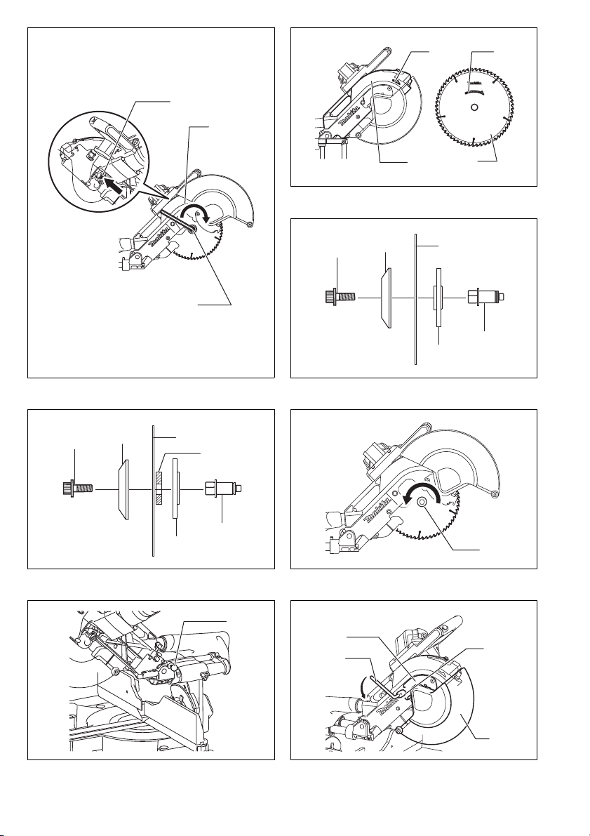
Adjusting the bevel angle (Fig. 13, 14 & 15)
To adjust the bevel angle, loosen the lever at the rear of
the tool counterclockwise. Push the latch lever forward as
shown in the figure fully while supporting the weight of
the saw head so as to release the pressure on the lock
pin.
When tilting the carriage to the right, tilt the carriage to
the left slightly after loosening the lever and press the
releasing button. With the releasing button being
pressed, tilt the carriage to the right.
Tilt the saw blade until the pointer points to the desired
angle on the bevel scale. Then tighten the lever clockwise firmly to secure the arm.
When the latch lever is pulled towards the front of the
saw, the saw blade can be locked using positive stops at
the right and left 22.5 ° and 33.9 ° angle to the base surface.
When the latch lever is pushed to the back of the saw as
shown in the figure, the saw blade can be locked at any
desired angle within the specified bevel angle range.
CAUTION:
• After changing the bevel angle, always secure the arm
by tightening the lever clockwise.
NOTICE:
• When tilting the saw blade be sure the handle is fully
raised.
• When changing bevel angles, be sure to position the
kerf boards appropriately as explained in the “Positioning kerf boards” section.
19

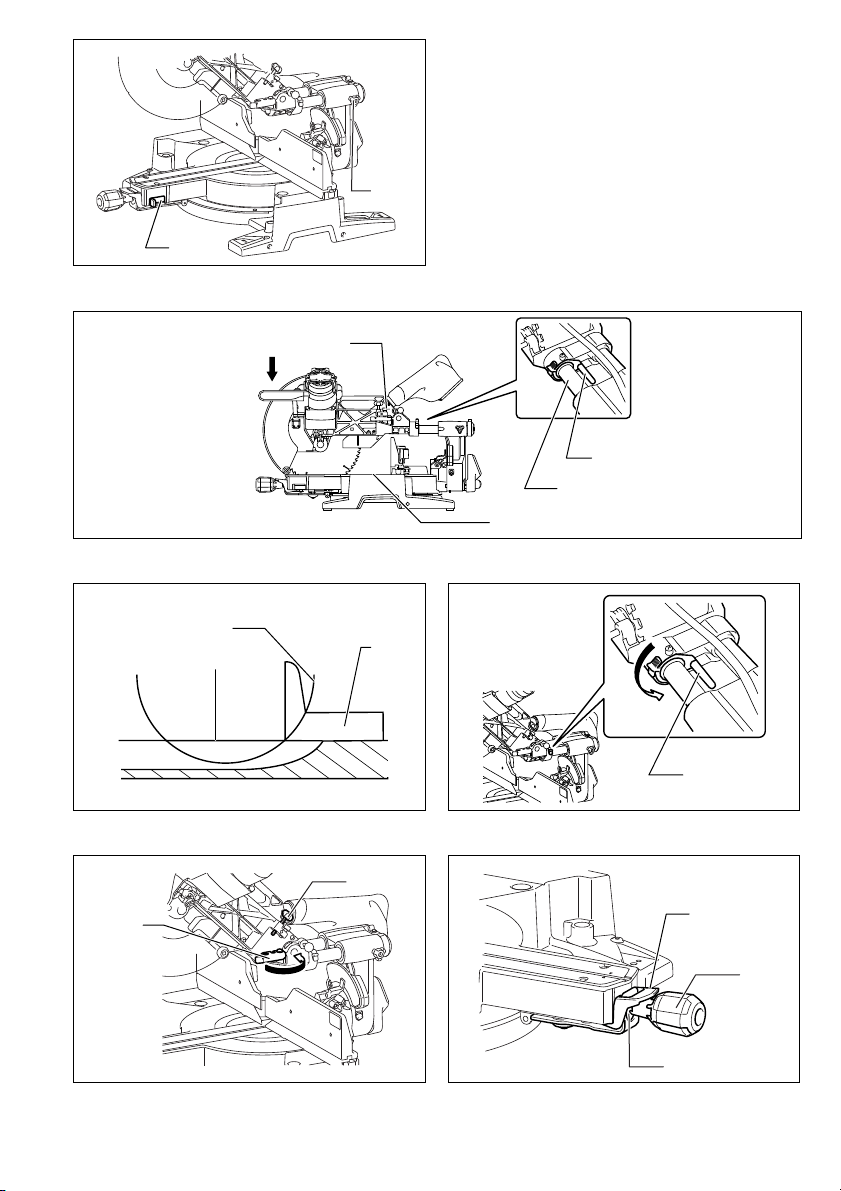
Slide lock adjustment (Fig. 16)
To lock the lower slide pole, pull the lock lever towards
the front of the saw.
To lock the upper slide pole, turn the locking screw clockwise.
Switch action
For European countries (Fig. 17)
To prevent the switch trigger from being accidentally
pulled, a lock-off button is provided. To start the tool,
push the lever to the left, press in the lock-off button and
then pull the switch trigger. Release the switch trigger to
stop.
WARNING:
• Before plugging in the tool, always check to see
that the switch trigger actuates properly and
returns to the “OFF” position when released. Do
not pull the switch trigger hard without pressing in
the lock-off button. This can cause switch breakage. Operating a tool with a switch that does not actu-
ate properly can lead to loss of control and serious
personal injury.
A hole is provided in the switch trigger for insertion of
padlock to lock the tool off.
For all countries other than European countries
(Fig. 18)
To prevent the switch trigger from being accidentally
pulled, a lock-off button is provided. To start the tool,
press in the lock-off button and pull the switch trigger.
Release the switch trigger to stop.
WARNING:
• Before plugging in the tool, always check to see
that the switch trigger actuates properly and
returns to the “OFF” position when released. Do
not pull the switch trigger hard without pressing in
the lock-off button. This can cause switch breakage. Operating a tool with a switch that does not actu-
ate properly can lead to loss of control and serious
personal injury.
A hole is provided in the switch trigger for insertion of
padlock to lock the tool off.
WARNING:
• Do not use a lock with a shank or cable any smaller
than 6.35 mm in diameter. A smaller shank or cable
may not properly lock the tool in the off position and
unintentional operation may occur resulting in serious
personal injury.
• NEVER use tool without a fully operative switch
trigger. Any tool with an inoperative switch is HIGHLY
DANGEROUS and must be repaired before further
usage or serious personal injury may occur.
• For your safety, this tool is equipped with a lock-off button which prevents the tool from unintended starting.
NEVER use the tool if it runs when you simply pull the
switch trigger without pressing the lock-off button. A
switch in need of repair may result in unintentional
operation and serious personal injury. Return tool to a
Makita service center for proper repairs BEFORE further usage.
• NEVER defeat the lock-off button by taping down or
some other means. A switch with a defeated lock-off
button may result in unintentional operation and serious
personal injury.
Lighting up the lamps (Fig. 19)
For Models LS1216F and LS1216FL only
CAUTION:
• This is not a rainproof light. Do not wash the light in
water or use it in a rain or a wet area. Such a conduct
can cause an electric shock and fume.
• Do not touch the lens of the light, as it is very hot while
it is lighted or shortly after it is turned off. This may
cause a burn to a human body.
• Do not apply impact to the light, which may cause damage or shorted service time to it.
• Do not keep casting the beam of the light to your eyes.
This can cause your eyes to be hurt.
• Do not cover the light with clothes, carton, cardboard or
similar objects while it is lighted, which can cause a fire
or an ignition.
To turn on the light, press the upper position (I) of the
switch. To turn off the light, press the lower position (O) of
the switch.
Move the light to shift an area of lighting.
NOTE:
• Use a dry cloth to wipe the dirt off the lens of lamp. Be
careful not to scratch the lens of light, or it may lower
the illumination.
Electronic function
Constant speed control
• The tool is provided with an electronic speed control
which helps maintain a constant blade rotation speed
even under load. A constant blade rotation speed will
result in a very smooth cut.
Soft start feature
• This function allows the smooth start-up of the tool by
limiting the start-up torque.
Laser beam action
For Models LS1216L and LS1216FL only
CAUTION:
• Never look into the laser beam. Direct laser beam may
injure your eyes.
• LASER RADIATION, DO NOT STARE INTO THE
BEAM OR VIEW DIRECTLY WITH OPTICAL INSTRUMENTS, CLASS 2M LASER PRODUCT.
To turn on the laser beam, press the upper position (I) of
the switch. To turn off the laser beam, press the lower
position (O) of the switch. (Fig. 20)
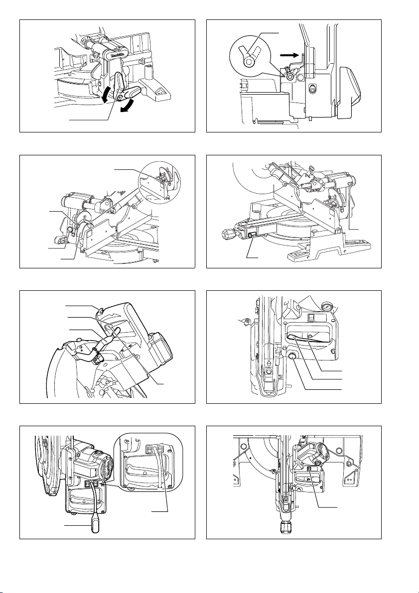
Laser line can be shifted to either the left or right side of
the saw blade by adjusting the adjusting screw as follows. (Fig. 21)
1. Loosen the adjusting screw by turning it counter-
clockwise.
2. With the adjusting screw loosened, slide the adjust-
ing screw to the right or left as far as it goes.
3. Tighten the adjusting screw firmly at the position
where it stops sliding.
Laser line is factory adjusted so that it is positioned within
1 mm from the side surface of the blade (cutting position).
NOTE:
• When laser line appears dim and hard to see because
of direct sunlight, relocate the work area to a place
where there is less direct sunlight.
20

Aligning the laser line (Fig. 22)
Laser line can be shifted to either the left or right side of
the blade according to the applications of cutting. Refer
to explanation titled “Laser beam action” regarding its
shifting method.
NOTE:
• Use wood facing against the guide fence when aligning
the cutting line with the laser line at the side of guide
fence in compound cutting (bevel angle 45 degrees and
miter angle right 45 degrees).
A) When you obtain the correct size on the left side of
workpiece
• Shift the laser line to the left of the blade.
B) When you obtain the correct size on the right side
of workpiece
• Shift the laser line to the right of the blade.
Align the cutting line on your workpiece with the laser
line.
ASSEMBLY
WARNING:
• Always be sure that the tool is switched off and
unplugged before working on the tool. Failure to
switch off and unplug the tool may result in serious personal injury.
Storing wrench
For model with hex wrench (Fig. 23)
The hex wrench is stored as shown in the figure. When
the hex wrench is needed it can be pulled out of the
wrench holder.
After using the hex wrench it can be stored by returning it
to the wrench holder.
For model with socket wrench (Fig. 24)
The socket wrench is stored as shown in the figure.
When the socket wrench is needed it can be pulled out of
the wrench holder.
After using the socket wrench it can be stored by returning it to the wrench holder.
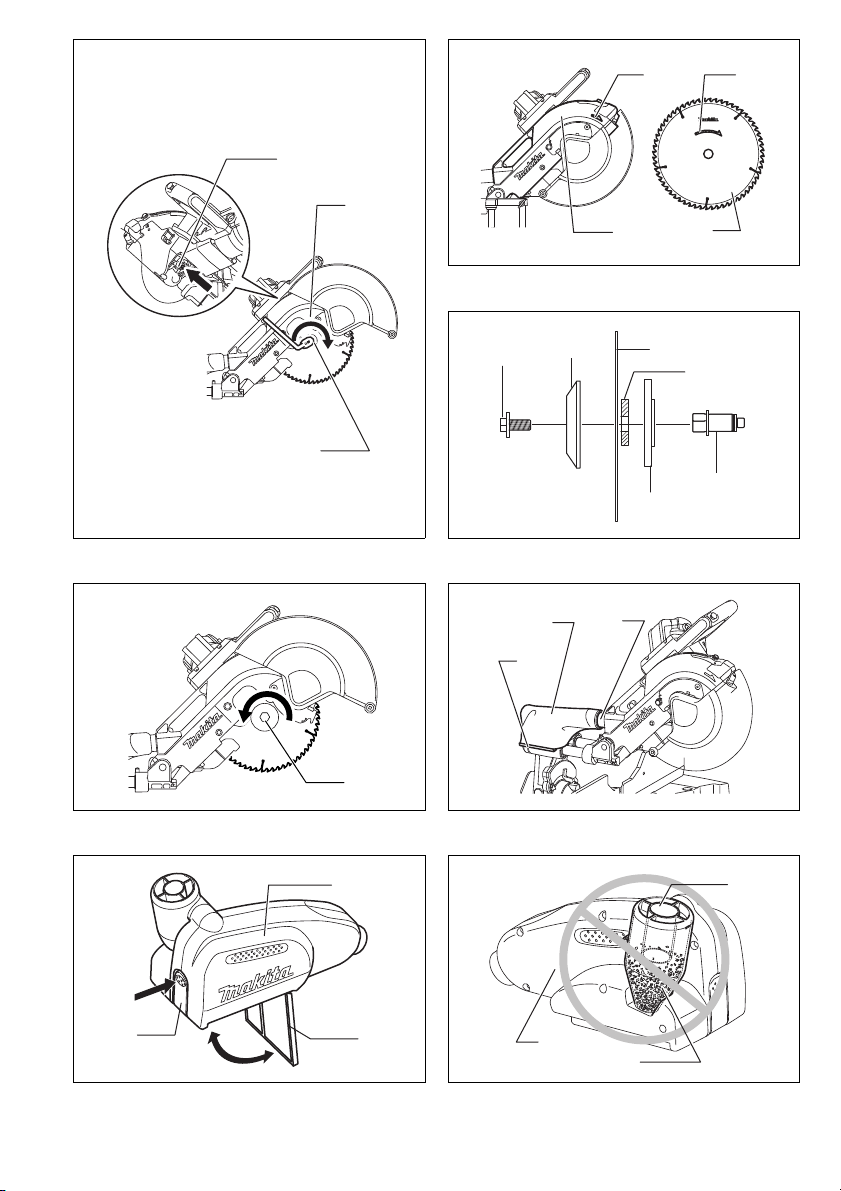
Installing or removing saw blade
WARNING:
• Always be sure that the tool is switched off and
unplugged before installing or removing the blade.
Accidental start up of the tool may result in serious personal injury.
For model with hex wrench (Fig. 25, 26, 27, 28, 29, 30
& 31)
WARNING:
• Use only the Makita hex wrench provided to install
or remove the blade. Failure to use the wrench may
result in overtightening or insufficient tightening of the
hex socket bolt and serious personal injury.
Lock the handle in the raised position by pushing in the
stopper pin.
To remove the blade, use the hex wrench to loosen the
hex socket bolt holding the center cover by turning it
counterclockwise. Raise the blade guard and center
cover.
Press the shaft lock to lock the spindle and use the hex
wrench to loosen the hex socket bolt clockwise. Then
remove the hex socket bolt, outer flange and blade.
NOTE:
• In some countries, tools have a ring separated from an
inner flange.
If the inner flange is removed be sure to install it on the
spindle with its protrusion facing away from the blade. If
the flange is installed incorrectly the flange will rub
against the machine.
WARNING:
• Before mounting the blade onto the spindle, always
be sure that the correct inner flange or ring for the
blade’s arbor hole you intend to use is installed.
Use of the incorrect inner flange or ring may result in
the improper mounting of the blade causing blade
movement and severe vibration resulting in possible
loss of control during operation and in serious personal
injury.
To install the blade, mount it carefully onto the spindle,
making sure that the direction of the arrow on the surface
of the blade matches the direction of the arrow on the
blade case.
Install the outer flange and hex socket bolt, and then use
the hex wrench to tighten the hex socket bolt (lefthanded) securely counterclockwise while pressing the
shaft lock.
Return the blade guard and center cover to its original
position. Then tighten the hex socket bolt clockwise to
secure the center cover. Release the handle from the
raised position by pulling the stopper pin. Lower the handle to make sure that the blade guard moves properly.
Make sure the shaft lock has released spindle before
making cut.
For model with socket wrench (Fig. 32, 33, 34, 35, 36
& 37)
WARNING:
• Use only the Makita socket wrench provided to
install or remove the blade. Failure to use the wrench
may result in overtightening or insufficient tightening of
the hex bolt and serious personal injury.
Lock the handle in the raised position by pushing in the
stopper pin.
To remove the blade, use the socket wrench to loosen
the hex bolt holding the center cover by turning it counterclockwise. Raise the blade guard and center cover.
Press the shaft lock to lock the spindle and use the
socket wrench to loosen the hex bolt clockwise. Then
remove the hex bolt, outer flange and blade.
NOTE:
• If the inner flange is removed be sure to install it on the
spindle with its protrusion facing away from the blade. If
the flange is installed incorrectly the flange will rub
against the machine.
21

WARNING:
• Before mounting the blade onto the spindle, always
be sure that the correct ring for the blade's arbor
hole you intend to use is installed between the
inner and the outer flanges. Use of the incorrect
arbor hole ring may result in the improper mounting of
the blade causing blade movement and severe vibration resulting in possible loss of control during operation and in serious personal injury.
To install the blade, mount it carefully onto the spindle,
making sure that the direction of the arrow on the surface
of the blade matches the direction of the arrow on the
blade case.
Install the outer flange and hex bolt, and then use the
socket wrench to tighten the hex bolt (left-handed)
securely counterclockwise while pressing the shaft lock.
Return the blade guard and center cover to its original
position. Then tighten the hex bolt clockwise to secure
the center cover. Release the handle from the raised
position by pulling the stopper pin. Lower the handle to
make sure that the blade guard moves properly. Make
sure the shaft lock has released spindle before making
cut.
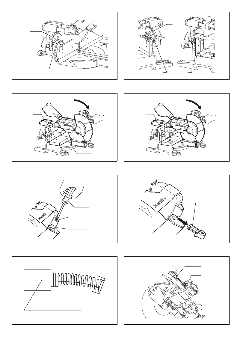
Dust bag (Fig. 38)
The use of the dust bag makes cutting operations
cleaner and dust collection easier. To attach the dust
bag, fit it onto the dust nozzle.
When the dust bag is about half full, remove the dust bag
from the tool and pull the fastener out. Empty the dust
bag of its contents, tapping it lightly so as to remove particles adhering to the insides which might hamper further
collection.
NOTE:
• If you connect a vacuum cleaner to your saw, cleaner
operations can be performed.
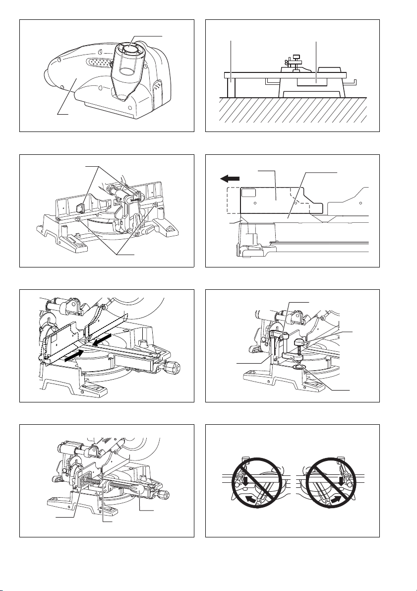
Dust box (optional accessory) (Fig. 39, 40 & 41)
Insert the dust box into the dust nozzle.
Empty the dust box when necessary.
To empty the dust box, open the cover by pushing the
button and dispose of the sawdust. Return the cover to
the original position and lock it in place. Dust box can
easily be removed by pulling it out while turning it near
the dust nozzle on the tool.
NOTE:
• If you connect a Makita vacuum cleaner to this tool,
cleaner operations can be performed.
NOTICE:
• Empty the dust box before collected sawdust level
reaches the cylinder section.
Securing workpiece
WARNING:
• It is extremely important to always secure the workpiece correctly with the proper type of vise or
crown molding stoppers. Failure to do so may result
in serious personal injury and cause damage to the tool
and/or the workpiece.
• After a cutting operation do not raise the blade
until it has come to a complete stop. The raising of a
coasting blade may result in serious personal injury
and damage to the workpiece.
• When cutting a workpiece that is longer than the
support base of the saw, the material should be
supported the entire length beyond the support
base and at the same height to keep the material
level. Proper workpiece support will help avoid blade
pinch and possible kickback which may result in serious personal injury. Do not rely solely on the vertical
vise and/or horizontal vise to secure the workpiece.
Thin material tends to sag. Support workpiece over its
entire length to avoid blade pinch and possible KICKBACK. (Fig. 42)
Guide fence (SLIDING FENCES which are upper
and lower fences) adjustment
WARNING:
• Before operating the tool, make sure that the upper and
lower fences are secured firmly.
• Before bevel-cutting, make sure that no part of the
tool, especially the blade, contacts the upper and
lower fences when fully lowering and raising the
handle in any position and while moving the carriage through its full range of travel. If the tool or
blade makes contact with the fence this may result in
kickback or unexpected movement of the material and
serious personal injury.
The lower fences can be moved inward and outward by
loosening the clamping screws. (Fig. 43)
A red indicating area will appear as the lower fences are
moved inward and will disappear as the lower fences are
moved outward.
The upper fences can be removed or moved inward and
outward by loosening the levers. (Fig. 44)
In case of bevel-cutting, adjust the lower and upper fence
positions to be as close to the blade as practical to provide maximum workpiece support, and make sure that no
part of the tool, especially the blade, contacts the lower
and upper fences when lowering and raising the handle
fully at any position and pulling or pushing the carriage all
the way at the lowest position. (Fig. 45)
Before cutting operations, make a dry run with the saw
turned off and unplugged, then check clearance between
fences and moving parts.
Before cutting operations, firmly secure lower fences by
tightening the clamping screws and upper fences by
tightening the levers.
When bevel-cutting operations are complete, don’t forget
to return the upper fences to the original position and
return it.
Vertical vise (Fig. 46)
The vertical vise can be installed in two positions on
either the left or right side of the base. Insert the vise rod
into the hole in the base.
Position the vise arm according to the thickness and
shape of the workpiece and secure the vise arm by tightening the screw. If the screw to secure the vise arm contacts the carriage, install the screw on the opposite side
of vise arm. Make sure that no part of the tool contacts
the vise when lowering the handle fully and pulling or
pushing the carriage all the way. If some part contacts
the vise, re-position the vise.
22

Press the workpiece flat against the guide fence and the
turn base. Position the workpiece at the desired cutting
position and secure it firmly by tightening the vise knob.
Turning the vise knob to 90° counterclockwise allows the
vise knob to be moved up and down, facilitating the quick
setting of workpiece. To secure the workpiece after setting, turn the vise knob clockwise.
WARNING:
• The workpiece must be secured firmly against the
turn base and guide fence with the vise during all
operations. If the workpiece is not properly secured
against the fence the material may move during the
cutting operation causing possible damage to the
blade, causing the material to be thrown and loss of
control resulting in serious personal injury.
Horizontal vise (optional accessory) (Fig. 47 & 48)
The horizontal vise can be installed in two positions on
either the left or right side of the base.
When performing 15° or greater miter cuts, install the
horizontal vise on the side opposite the direction in which
the turn base is to be turned.
By flipping the vise nut counterclockwise, the vise is
released, and rapidly moves in and out. To grip the workpiece, push the vise knob forward until the vise plate contacts the workpiece and flip the vise nut clockwise. Then
turn the vise knob clockwise to secure the workpiece.
The maximum width of workpiece which can be secured
by the horizontal vise is 215 mm.
WARNING:
• Always rotate the vise nut clockwise until the workpiece is properly secured. If the workpiece is not
properly secured the material may move during the cutting operation causing possible damage to the blade,
causing the material to be thrown and loss of control
resulting in serious personal injury.
• When cutting a thin workpiece, such as base boards,
against the fence, always use the horizontal vise.
Holders (optional accessory) (Fig. 49)
The holders can be installed on either side as a convenient means of holding workpieces horizontally. Slip the
holder rods into the holes in the base and adjust their
length according to the workpiece to be held. Then
tighten the holders securely with the screws.
WARNING:
• Always support a long workpiece so it is level with
the top surface of the turn base for an accurate cut
and to prevent dangerous loss of tool control.
Proper workpiece support will help avoid blade pinch
and possible kickback which may result in serious personal injury.
OPERATION
NOTICE:
• Before use, be sure to release the handle from the lowered position by pulling the stopper pin.
• Do not apply excessive pressure on the handle when
cutting. Too much force may result in overload of the
motor and/or decreased cutting efficiency. Push down
handle with only as much force as is necessary for
smooth cutting and without significant decrease in
blade speed.
• Gently press down the handle to perform the cut. If the
handle is pressed down with force or if lateral force is
applied, the blade will vibrate and leave a mark (saw
mark) in the workpiece and the precision of the cut will
be impaired.
• During a slide cut, gently push the carriage toward the
guide fence without stopping. If the carriage movement
is stopped during the cut, a mark will be left in the workpiece and the precision of the cut will be impaired.
WARNING:
• Make sure the blade is not contacting the workpiece, etc. before the switch is turned on. Tur ning
the tool on with the blade in contact with the workpiece
may result in kickback and serious personal injury.
1. Press cutting (cutting small workpieces)
(Fig. 50)
Workpieces up to 87 mm high and 183 mm wide can be
cut in the following manner.
After turning the stopper lever clockwise and sliding the
carriage to your desired position, push the carriage
toward the guide fence fully and tighten the locking screw
clockwise and pull the lock lever towards the front of the
saw to secure the carriage. Secure the workpiece correctly with the proper type of vise or crown molding stoppers. Switch on the tool without the blade making any
contact and wait until the blade attains full speed before
lowering. Then gently lower the handle to the fully lowered position to cut the workpiece. When the cut is completed, switch off the tool and WAIT UNTIL THE BLADE
HAS COME TO A COMPLETE STOP before returning
the blade to its fully elevated position.
WARNING:
• Firmly tighten the locking screw clockwise and pull
the lock lever towards the front of the saw so that
the carriage will not move during operation. Insuffi-
cient tightening of the locking screw may cause possible kickback which may result in serious personal
injury.
2. Slide (push) cutting (cutting wide workpieces)
(Fig. 51 & 52)
Loosen the locking screw counterclockwise and also
push forward the lock lever so that the carriage can slide
freely. Secure the workpiece with the proper type of vise.
Pull the carriage toward you fully. Switch on the tool without the blade making any contact and wait until the blade
attains full speed. Press the handle down and PUSH
THE CARRIAGE TOWARD THE GUIDE FENCE AND
THROUGH THE WORKPIECE. When the cut is completed, switch off the tool and WAIT UNTIL THE BLADE
HAS COME TO A COMPLETE STOP before returning
the blade to its fully elevated position.
23

WARNING:
• Whenever performing a slide cut, first pull the carriage full towards you and press the handle all the
way down, then push the carriage toward the guide
fence. Never start the cut with the carriage not
pulled fully toward you. If you perform the slide cut
without the carriage pulled fully toward you unexpected
kickback may occur and serious personal injury may
result.
• Never attempt to perform a slide cut by pulling the
carriage towards you. Pulling the carriage towards
you while cutting may cause unexpected kickback
resulting in possible serious personal injury.
• Never perform the slide cut with the handle locked in
the lowered position.
• Never loosen the knob which secures the carriage
while the blade is rotating. A loose carriage while cutting may cause unexpected kickback resulting in possible in serious personal injury.
3. Miter cutting
Refer to the previously covered “Adjusting the miter
angle”.
4. Bevel cut (Fig. 53)
Loosen the lever and tilt the saw blade to set the bevel
angle (Refer to the previously covered “Adjusting the
bevel angle”). Be sure to retighten the lever firmly to
secure the selected bevel angle safely. Secure the workpiece with a vise. Make sure the carriage is pulled all the
way back toward the operator. Switch on the tool without
the blade making any contact and wait until the blade
attains full speed. Then gently lower the handle to the
fully lowered position while applying pressure in parallel
with the blade and PUSH THE CARRIAGE TOWARD
THE GUIDE FENCE TO CUT THE WORKPIECE. When
the cut is completed, switch off the tool and WAIT UNTIL
THE BLADE HAS COME TO A COMPLETE STOP
before returning the blade to its fully elevated position.
WARNING:
• After setting the blade for a bevel cut, before operating the tool ensure that the carriage and blade
will have free travel throughout the entire range of
the intended cut. Interruption of the carriage or blade
travel during the cutting operation may result in kickback and serious personal injury.
Measuring
Measure the wall length and adjust workpiece on table to cut wall contact edge to desired length. Always make sure
that cut workpiece length at the back of the workpiece is the same as wall length. Adjust cut length for angle of cut.
Always use several pieces for test cuts to check the saw angles.
When cutting crown and cove moldings, set the bevel angle and miter angle as indicated in the table (A) and position
the moldings on the top surface of the saw base as indicated in the table (B).
In the case of left bevel cut
Table (A )
Molding position
For inside corner
For outside corner
006361
in Fig. 55 & 56
(1)
(2)
(3)
(4) Right 31.6° Right 35.3°
52/38° type 45° type 52/38° type 45° type
Left 33.9° Left 30°
• While making a bevel cut keep hands out of the
path of the blade. The angle of the blade may confuse
the operator as to the actual blade path while cutting
and contact with the blade will result in serious personal injury.
• The blade should not be raised until it has come to
a complete stop. During a bevel cut the piece cut off
may come to rest against the blade. If the blade is
raised while it is rotating the cut-off piece maybe
ejected by the blade causing the material to fragment
which may result in serious personal injury.
NOTICE:
• When pressing down the handle, apply pressure in parallel with the blade. If a force is applied perpendicularly
to the turn base or if the pressure direction is changed
during a cut, the precision of the cut will be impaired.
• Before bevel-cutting, an adjustment of the upper fence
and lower fence maybe required. Refer to the section
titled “Guide fence adjustment”.
5. Compound cutting
Compound cutting is the process in which a bevel angle
is made at the same time in which a miter angle is being
cut on a workpiece. Compound cutting can be performed
at the angle shown in the table.
Miter angle Bevel angle
Left and Right 0° – 45° Left and Right 0° – 45°
009713
When performing compound cutting, refer to “Press cutting”, “Slide cutting”, “Miter cutting” and “Bevel cut” explanations.
6. Cutting crown and cove moldings
Crown and cove moldings can be cut on a compound
miter saw with the moldings laid flat on the turn base.
There are two common types of crown moldings and one
type of cove moldings; 52/38° wall angle crown molding,
45° wall angle crown molding and 45° wall angle cove
molding. See illustrations. (Fig. 54)
There are crown and cove molding joints which are made
to fit “Inside” 90° corners ((1) and (2) in Fig. 55 & 56) and
“Outside” 90° corners ((3) and (4) in Fig. 55 & 56).
Bevel angle Miter angle
Right 31.6° Right 35.3°
Left 31.6° Left 35.3°
24

Table ( B)
Molding position
in Fig. 55 & 56
For inside corner
(1)
(2)
(3)
For outside corner
006362
Example:
In the case of cutting 52/38° type crown molding for position (1) in Fig. 55 & 56:
• Tilt and secure bevel angle setting to 33.9° LEFT.
• Adjust and secure miter angle setting to 31.6° RIGHT.
• Lay crown molding with its broad back (hidden) surface down on the turn base with its CEILING CONTACT EDGE
against the guide fence on the saw.
• The finished piece to be used will always be on the LEFT side of the blade after the cut has been made.
(4)
Molding edge against guide fence Finished piece
Ceiling contact edge should be
against guide fence.
Finished piece will be on the Left
side of blade.
Wall contact edge should be against
guide fence.
Ceiling contact edge should be
against guide fence.
Finished piece will be on the Right
side of blade.
In the case of right bevel cut
Table ( A)
Bevel angle Miter angle
52/38° type 45° type 52/38° type 45° type
Right 31.6° Right 35.3°
Right 33.9° Right 30°
Left 31.6° Left 35.3°
For inside corner
For outside corner
006363
Molding position
in Fig. 55 & 56
(1)
(2)
(3)
(4) Right 31.6° Right 35.3°
Table ( B)
For inside corner
For outside corner
006364
Molding position
in Fig. 55 & 56
(1)
(2)
(3)
(4)
Molding edge against guide fence Finished piece
Wall contact edge should be against
guide fence.
Ceiling contact edge should be
against guide fence.
Wall contact edge should be against
guide fence.
Finished piece will be on the Right
side of blade.
Finished piece will be on the Left
side of blade.
Example:
In the case of cutting 52/38° type crown molding for position (1) in Fig. 55 & 56:
• Tilt and secure bevel angle setting to 33.9° RIGHT.
• Adjust and secure miter angle setting to 31.6° RIGHT.
• Lay crown molding with its broad back (hidden) surface down on the turn base with its WALL CONTACT EDGE
against the guide fence on the saw.
• The finished piece to be used will always be on the RIGHT side of the blade after the cut has been made.
Crown molding stoppers (optional accessories) allow easier cuts of crown molding without tilting the saw blade. Install
them on the base as shown in the figures. (Fig. 57 & 58)
Fig. 57: At right 45° miter angle
Fig. 58: At left 45° miter angle
Position crown molding with its WALL CONTACT EDGE against the guide fence and its CEILING CONTACT EDGE
against the crown molding stoppers as shown in the figure (Fig. 59). Adjust the crown molding stoppers according to
the size of the crown molding. Tighten the screws to secure the crown molding stoppers. Refer to the table (C) for the
miter angle.
25
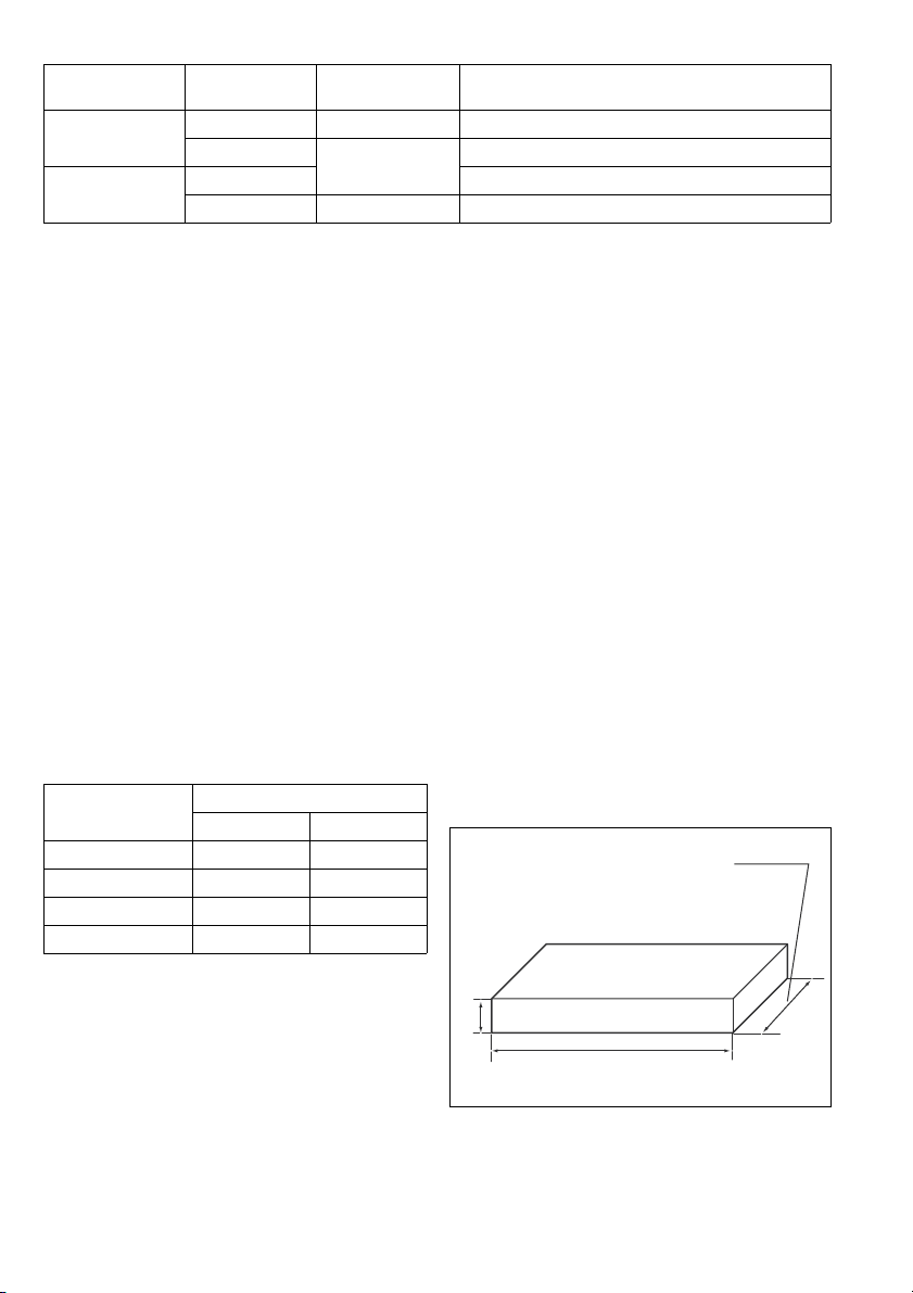
Table (C )
0° Miter angle: Over 450 mm (17-3/4”)
45° Miter angle: Over 325 mm (12-3/4”)
38 mm (1-1/2”)
Over 760 mm (30”)
Molding position
in Fig. 55 & 56
For inside corner
For outside corner
006365
7. Cutting aluminum extrusion
When securing aluminum extrusions, use spacer blocks
or pieces of scrap as shown in Fig. 60 to prevent deformation of the aluminum. Use a cutting lubricant when
cutting the aluminum extrusion to prevent build-up of the
(1) Right 45° Save the right side of blade
(2)
(3) Save the right side of blade
(4) Right 45° Save the left side of blade
Miter angle Finished piece
Left 45°
aluminum material on the blade.
WARNING:
• Never attempt to cut thick or round aluminum
extrusions. Thick or round aluminum extrusions can
be difficult to secure and may work loose during the
cutting operation which may result in loss of control and
serious personal injury.
8. Wood facing (Fig. 61)
Use of wood facing helps to assure splinter-free cuts in
workpieces. Attach a wood facing to the guide fence
using the holes in the guide fence and 6 mm screws.
See the figure concerning the dimensions for a suggested wood facing.
CAUTION:
• Use straight wood of even thickness as the wood facing.
• In order to completely cut through workpieces with a
height of 102 mm to 120 mm a wood facing should be
used on the guide fence. The wood facing will space
the workpiece away from the fence allowing the blade
to complete a deeper cut.
Example:
When cutting workpieces 115 mm and 120 mm high, use
a wood facing with the following thickness.
Miter angle
Thickness of wood facing
115 mm 120 mm
0° 35 mm 60 mm
Left and Right 45° 30 mm 45 mm
Left and Right 52° 25 mm 35 mm
Right 60° 25 mm 35 mm
010048
WARNING:
• Use screws to attach the wood facing to the guide
fence. The screws should be installed so that the
screw heads are below the surface of the wood facing so that they will not interfere with the positioning of the material being cut. Misalignment of the
material being cut can cause unexpected movement
during the cutting operation which may result in a loss
of control and serious personal injury.
NOTICE:
• When the wood facing is attached, do not turn the turn
base with the handle lowered. The blade and/or the
wood facing will be damaged.
Save the left side of blade
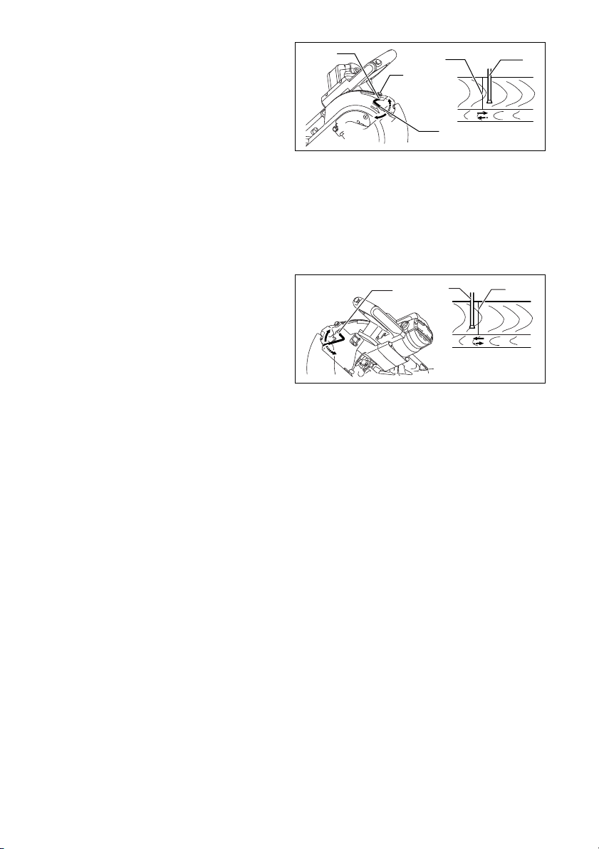
9. Groove cutting (Fig. 62)
A dado type cut can be made by proceeding as follows:
Adjust the lower limit position of the blade using the
adjusting screw and the stopper arm to limit the cutting
depth of the blade. Refer to “Stopper arm” section
described previously.
After adjusting the lower limit position of the blade, cut
parallel grooves across the width of the workpiece using
a slide (push) cut as shown in the figure. Then remove
the workpiece material between the grooves with a
chisel.
WARNING:
• Do not attempt to perform this type of cut by using
a wider type blade or dado blade. Attempting to
make a groove cut with a wider blade or dado blade
could lead to unexpected cutting results and kickback
which may result in serious personal injury.
• Be sure to return the stopper arm to the original
position when performing other than groove cutting. Attempting to make cuts with the stopper arm in
the incorrect position could lead to unexpected cutting
results and kickback which may result in serious personal injury.
10. Special Max Width Cutting Capacities Technique
The maximum width cutting capacity of this tool can be
achieved by following the steps below:
For the maximum cutting width of this tool refer to the
SPECIFICATIONS under “Special Max Width Cutting
Capacities”
1) Set the tool at 0° or 45° miter angle and make sure
that the turn base is locked. (Refer to the section
titled “Adjusting the miter angle”.)
010565
2) Remove both right and left upper fences temporarily
and set aside
26

3) Cut a platform to the dimensions indicated in the
drawing above using a 38 mm thick, flat stock material such as wood, plywood or particle board.
WARNING:
• Be sure to use flat stock as a platform. Stock that is
not flat may move during the cutting operation which
may result in kickback and serious personal injury.
NOTE:
• The maximum cutting capacity in height will be reduced
by the same amount as the platform thickness.
4) Place the platform on the tool so that it extends
equally over each side of the tool base.
Secure the platform to the tool using four 6 mm
wood screws through four holes in the lower fences.
(Fig. 63)
WARNING:
• Make sure that the platform is laying flat against
the tool base and secured firmly to the lower
fences using the four screw holes provided. Failure
to properly secure the platform may result in movement
and possible kickback resulting in serious personal
injury.
• Ensure that the tool is firmly mounted to a stable
and flat surface. Failure to properly mount and secure
the tool could cause the tool to be unstable resulting in
a loss of control and/or the tool falling which may result
in serious personal injury.
5) Install both of the removed upper fences on the tool.
WARNING:
• Do not use the tool without upper fences installed.
The upper fences provide the adequate support
required to cut the workpiece.
If the workpiece is not supported properly it may move
resulting in possible loss of control, kickback and serious personal injury.
6) Place the workpiece to be cut on the platform
secured to the tool.
7) Secure the workpiece firmly against the upper
fences with a vise before cutting.
8) Make a cut through the workpiece slowly according
to the operation titled “Slide (push) cutting (cutting
wide workpieces).” (Fig. 64)
WARNING:
• Ensure that the workpiece is secured with the vise
and make the cut slowly. Failure to properly secure
the workpiece and to cut slowly may cause the workpiece to move resulting in possible kickback and serious personal injury.
• Beware that after several cuts are performed at var-
ious miter angles the platform may become weakened. If the platform becomes weakened due to the
multiple kerf cuts left in the material the platform should
be replaced. If the weakened platform is not replaced it
may cause the workpiece to move, during cutting,
resulting in possible kickback and serious personal
injury.
Carrying tool
Make sure that the tool is unplugged. Secure the blade at
0° bevel angle and the turn base at the full right miter
angle position. Secure the slide poles so that the lower
slide pole is locked in the position of the carriage fully
pulled to operator and the upper poles are locked in the
position of the carriage fully pushed forward to the guide
fence (refer to the section titled “Slide lock adjustment”.)
Lower the handle fully and lock it in the lowered position
by pushing in the stopper pin. (Fig. 65)
WARNING:
• Stopper pin is only for carrying and storage purposes and should never be used for any cutting
operations. The use of the stopper pin for cutting oper-
ations may cause unexpected movement of the saw
blade resulting in kickback and serious personal injury.
Carry the tool by holding both sides of the tool base as
shown in the figure. If you remove the holders, dust bag,
etc., you can carry the tool more easily. (Fig. 66)
CAUTION:
• Always secure all moving portions before carrying the
tool. If portions of the tool move or slide while being
carried loss of control or balance may occur resulting in
personal injury.
MAINTENANCE
WARNING:
• Always be sure that the tool is switched off and
unplugged before attempting to perform inspection
or maintenance. Failure to unplug and switch off the
tool may result in accidental start up of the tool which
may result in serious personal injury.
• Always be sure that the blade is sharp and clean for
the best and safest performance. Attempting a cut
with a dull and/or dirty blade may cause kickback and
result in a serious personal injury.
NOTICE:
• Never use gasoline, benzine, thinner, alcohol or the
like. Discoloration, deformation or cracks may result.
Adjusting the cutting angle
This tool is carefully adjusted and aligned at the factory,
but rough handling may have affected the alignment. If
your tool is not aligned properly, perform the following:
1. Miter angle
Push the carriage toward the guide fence and tighten the
locking screw clockwise and pull the lock lever towards
the front of the saw to secure the carriage.
Turn the grip counterclockwise which secures the turn
base. Turn the turn base so that the pointer points to 0°
on the miter scale. Then turn the turn base slightly clockwise and counterclockwise to seat the turn base in the 0°
miter notch. (Leave as it is if the pointer does not point to
0°.) Loosen the hex socket bolts securing the guide fence
using the socket wrench.
Lower the handle fully and lock it in the lowered position
by pushing in the stopper pin. Square the side of the
blade with the face of the guide fence using a triangular
rule, try-square, etc. Then securely tighten the hex
socket bolts on the guide fence in order starting from the
right side. (Fig. 67)
Make sure that the pointer points to 0° on the miter scale.
If the pointer does not point to 0°, loosen the screw which
secures the pointer and adjust the pointer so that it will
point to 0°. (Fig. 68)
27
2. Bevel angle
1
2
3
4
5
1
2
3
Push the latch lever forward fully to release the positive
stops.
1) 0° bevel angle
Push the carriage toward the guide fence and
tighten the locking screw clockwise and pull the lock
lever towards the front of the saw to secure the carriage. Lower the handle fully and lock it in the lowered position by pushing in the stopper pin. Loosen
the lever at the rear of the tool. (Fig. 69)
Turn the hex socket bolt on the right side of the arm
holder two or three revolutions counterclockwise to
tilt the blade to the right. (Fig. 70)
Carefully square the side of the blade with the top
surface of the turn base using the triangular rule, trysquare, etc. by turning the hex socket bolt on the
right side of the arm holder clockwise. Then tighten
the lever securely. (Fig. 71)
Make sure that the pointers on the arm holder point
to 0° on the bevel scale on the arm. If they do not
point to 0°, loosen the screws which secure the
pointers and adjust them so that they will point to 0°.
(Fig. 72)
2) 45° bevel angle (Fig. 73)
Adjust the 45° bevel angle only after performing 0°
bevel angle adjustment. To adjust left 45° bevel
angle, loosen the lever and tilt the blade to the left
fully. Make sure that the pointer on the arm holder
points to 45° on the bevel scale on the arm. If the
pointer does not point to 45°, turn the left 45° bevel
angle adjusting bolt on the side of the arm until the
pointer points to 45°.
To adjust right 45° bevel angle, perform the same
procedure described above.
Adjustment of the laser line position (Fig. 74 & 75)
For models LS1216L and LS1216FL only
WARNING:
• Since the tool must be plugged in while adjusting
the laser line, special care must be taken to not
switch on the tool. Accidental start up of the tool may
result in serious personal injury.
CAUTION:
• Never look directly into the laser beam. Direct eye
exposure to the beam could cause serious damage to
the eyes.
• LASER RADIATION
Do not stare into beam.
NOTICE:
• Beware that impacts to the tool may cause the laser
line to be misaligned or may cause damage to the
laser, shortening its life.
Adjusting the laser line for the left side of the blade.
1 Screw to change the movable range of the adjusting
screw
2 Adjusting screw
3Hex wrench
4 Laser line
5 Saw blade
009514
Adjusting the laser line for the right side of the
blade.
1 Adjusting screw
2 Saw blade
3 Laser line
009515
For both adjustments, do as follows.
1. Make sure that the tool is unplugged.
2. Draw the cutting line on the workpiece and place it
on the turn table. At this time, do not secure the
workpiece with a vise or similar securing device.
3. Lower the blade by lowering the handle and just
check to see where the cutting line and the position
of the saw blade is. (Decide which position to cut on
the line of cut.)
4. After deciding the correct position of the line in rela-
tion to the blade, return the handle to the original
position. Secure the workpiece with the vertical vise
without shifting the workpiece from the pre-checked
position.
5. Plug the tool and turn on the laser switch.
6. Adjust the position of laser line as follows.
The position of laser line can be changed as the movable
range of the adjusting screw for the laser is changed by
turning two screws with a hex wrench. (The movable
range of laser line is factory adjusted within 1 mm from
the side surface of blade.)
To shift the laser line movable range further away from
the side surface of blade, turn the two screws counterclockwise after loosening the adjusting screw. Turn these
two screws clockwise to shift it closer to the side surface
of the blade after loosening the adjusting screw.
Refer to the section titled “Laser beam action” and adjust
the adjusting screw so that the cutting line on your workpiece is aligned with the laser line.
28

NOTE:
• Check the position of laser line regularly for accuracy.
• Have the tool repaired by a Makita authorized service
center for any failure on the laser unit.
Cleaning the laser light lens (Fig. 76 & 77)
For models LS1216L and LS1216FL only
If the lens for the laser light becomes dirty, or sawdust
adheres to it in such a way that the laser line is no longer
easily visible, unplug the saw and remove and clean the
lens for the laser light carefully with a damp, soft cloth.
Do not use solvents or any petroleum-based cleaners on
the lens.
To remove the lens for the laser light, remove the saw
blade before removing the lens according to the instructions in the section titled “Installing or removing saw
blade”.
Loosen but do not remove the screw which secures the
lens using a screwdriver.
Pull out the lens as shown in the figure.
NOTE:
• If the lens does not come out, loosen the screw further
and pull out the lens again without removing the screw.
Replacing carbon brushes (Fig. 78 & 79)
Remove and check the carbon brushes regularly.
Replace when they wear down to the limit mark. Keep
the carbon brushes clean and free to slip in the holders.
Both carbon brushes should be replaced at the same
time. Use only identical carbon brushes.
Use a screwdriver to remove the brush holder caps. Take
out the worn carbon brushes, insert the new ones and
secure the brush holder caps.
After replacing brushes, plug in the tool and break in
brushes by running tool with no load for about 10 minutes. Then check the tool while running and electric
brake operation when releasing the switch trigger. If the
electric brake is not working correctly, have the tool
repaired by a Makita service center.
After use
• After use, wipe off chips and dust adhering to the tool
with a cloth or the like. Keep the blade guard clean
according to the directions in the previously covered
section titled “Blade guard”. Lubricate the sliding portions with machine oil to prevent rust.
• When storing the tool, pull the carriage toward you fully
so that the slide pole is thoroughly inserted into the turn
base.
To maintain product SAFETY and RELIABILITY, repairs,
any other maintenance or adjustment should be performed by Makita Authorized Service Centers, always
using Makita replacement parts.
OPTIONAL ACCESSORIES
WARNING:
• These Makita accessories or attachments are recommended for use with your Makita tool specified
in this manual. The use of any other accessories or
attachments may result in serious personal injury.
• Only use the Makita accessory or attachment for its
stated purpose. Misuse of an accessory or attachment may result in serious personal injury.
If you need any assistance for more details regarding
these accessories, ask your local Makita Service Center.
• Steel & Carbide-tipped saw blades
Miter saw blades
Combination
Crosscutting
Fine cross cuts
Non-ferrous metals
miter saw blades
006526
• Vise assembly (Horizontal vise)
• Vertical vise
• Hex wrench 6
• Socket wrench 13
• Holder
•Dust bag
• Crown molding stopper set
• Triangular rule
•Dust box
• Hex wrench (For LS1216L and LS1216FL)
NOTE:
• Some items in the list may be included in the tool package as standard accessories. They may differ from
country to country.
For smooth and precise cutting in
various materials.
General purpose blade for fast
and smooth rip, crosscuts and
miters.
For smoother cross grain cuts.
Slices cleanly against the grain.
For sand-free cuts cleanly against
the grain.
For miters in aluminum, copper,
brass, tubing, and other non-ferrous metals.
29

Noise
The typical A-weighted noise level determined according
to EN61029:
Sound pressure level (
Sound power level (
Uncertainty (K): 3 dB (A)
L
): 91 dB (A)
pA
L
): 100 dB (A)
WA
Wear ear protection
ENG905-1
ENG900-1
Vibration
The vibration total value (tri-axial vector sum) determined
according to EN61029:
Vibration emission (a
Uncertainty (K): 1.5 m/s
): 2.5 m/s2 or less
h
2
ENG901-1
• The declared vibration emission value has been measured in accordance with the standard test method and
may be used for comparing one tool with another.
• The declared vibration emission value may also be
used in a preliminary assessment of exposure.
WARNING:
• The vibration emission during actual use of the power
tool can differ from the declared emission value
depending on the ways in which the tool is used.
• Be sure to identify safety measures to protect the operator that are based on an estimation of exposure in the
actual conditions of use (taking account of all parts of
the operating cycle such as the times when the tool is
switched off and when it is running idle in addition to
the trigger time).
ENH003-13
For European countries only
EC Declaration of Conformity
We Makita Corporation as the responsible manufacturer declare that the following Makita machine(s):
Designation of Machine: Slide Compound Miter Saw
Model No./ Type: LS1216, LS1216L, LS1216F,
LS1216FL
are of series production and
Conforms to the following European Directives:
2006/42/EC
And are manufactured in accordance with the following
standards or standardised documents:
EN61029
The technical documentation is kept by our authorised
representative in Europe who is:
Makita International Europe Ltd.
Michigan Drive, Tongwell,
Milton Keynes, Bucks MK15 8JD, England
20.1.2010
30
Tomoyasu Kato
Director
Makita Corporation
3-11-8, Sumiyoshi-cho,
Anjo, Aichi, 446-8502, JAPAN
 Loading...