

Makita LS1214FL, LS1214L, LS1214F, LS1214 Instruction Manual
INSTRUCTION MANUAL
MANUEL D'INSTRUCTION
MANUAL DE INSTRUCCIONES
Slide Compound Saw
Scie Multi Coupe
Sierra de Inglete Telescópica
LS1214
LS1214F
LS1214L
LS1214FL
IMPORTANT: Read Before Using.
IMPORTANT: Lire avant usage.
IMPORTANTE: Leer antes de usar.
005689
DOUBLE INSULATION
DOUBLE ISOLATION
DOBLE AISLAMIENTO
1

ENGLISH
SPECIFICATIONS
Model LS1214 / LS1214F / LS1214L/LS1214FL
Blade diameter 305 mm (12")
Hole diameter 25.4 mm (1")
Max. Miter angle Left 47° , Right 52°
Max. Bevel angle Left and Right 45°
Max. Cutting capacities (H x W)
Miter angle
45° (left) 0° 45° (right)
*71 mm x 260 mm *120 mm x 270 mm *50 mm x 260 mm
0°
(2-13/16" x 10-1/4") (4-3/4"" x 10-5/8") (2" x 10-1/4")
66 mm x 305 mm 115 mm x 308 mm 45 mm x 305 mm
(2-5/8" x 12") (4-1/2" x 12-1/8") (1-3/4" x 12")
(left)*71 mm x 155 mm
(2-13/16" x 6-1/8")
66 mm x 170 mm
45° (left and right)
(2-5/8" x 6-11/16")
(right)*71 mm x 175 mm
(2-13/16" x 6-7/8")
66 mm x 215 mm
(2-5/8" x 8-1/2")
52° (right) -
(Note)
* mark indicates that a wood facing with the following thickness is used.
Miter angle Thickness of wood
0° 20 mm (13/16")
45° (left and right) 15 mm (9/16")
52° (right) 15 mm (9/16")
No load speed (RPM) 3,200/min.
Laser Type (LS1214L, LS1214FL only)
Dimensions (L x W x H) LS1214/LS1214F…….723 mm x 520 mm x 696 mm
(28-1/2" x 20-1/2" x 27-1/2")
LS1214L/LS1214FL…….723 mm x 520 mm x 718 mm
(28-1/2" x 20-1/2" x 28-1/4")
Net weight LS1214 24.4 kg (53.8 lbs), LS1214F 24.6 kg (54.2 lbs)
LS1214L 25.3 kg(55.8 lbs), LS1214FL 25.5 kg(56.2 lbs)
• Due to our continuing programme of research and development, the specifications herein are subject to change without notice.
• Specifications may differ from country to country.
• Weight according to EPTA-Procedure 01/2003
Bevel angle
*120 mm x 185 mm
(4-3/4" x 7-1/4")
115 mm x 218 mm
(4-1/2" x 8-5/8")
*50 mm x 175 mm
(2" x 6-7/8")
45 mm x 215 mm
(1-3/4" x 8-1/2")
*120 mm x 160 mm
(4 - 3/4" x 6 - 5/16")
115 mm x 185 mm
-
(4-1/2" x 7-1/4")
Wavelength 655 nm, Maximum output 1mW (Laser Class II)
2

USA007-3
For Your Own Safety Read
Instruction Manual
Before Operating Tool
Save it for future reference
GENERAL SAFETY
PRECAUTIONS
(For All Tools)
1. KNOW YOUR POWER TOOL. Read the owner's
manual carefully. Learn the tool's applications
and limitations, as well as the specific
potential hazards peculiar to it.
2. KEEP GUARDS IN PLACE and in working
order.
3. REMOVE ADJUSTING KEYS AND WRENCHES.
Form habit of checking to see that keys and
adjusting wrenches are removed from tool
before turning it on.
4. KEEP WORK AREA CLEAN. Cluttered areas
and benches invite accidents.
5. DO NOT USE IN DANGEROUS ENVIRONMENT.
Do not use power tools in damp or wet
locations, or expose them to rain. Keep work
area well lighted. Do not use tool in presence
of flammable liquids or gases.
6. KEEP CHILDREN AWAY. All visitors should be
kept safe distance from work area.
7. MAKE WORKSHOP KID PROOF with padlocks,
master switches, or by removing starter keys.
8. DO NOT FORCE TOOL. It will do the job better
and safer at the rate for which it was designed.
9. USE RIGHT TOOL. Do not force tool or
attachment to do a job for which it was not
designed.
10. WEAR PROPER APPAREL. Do not wear loose
clothing, gloves, neckties, rings, bracelets, or
other jewelry which may get caught in moving
parts. Nonslip footwear is recommended.
Wear protective hair covering to contain long
hair.
11. ALWAYS USE SAFETY GLASSES. Also use
face or dust mask if cutting operation is dusty.
Everyday eyeglasses only have impact
resistant lenses, they are NOT safety glasses.
12. SECURE WORK. Use clamps or a vise to hold
work when practical. It's safer than using your
hand and it frees both hands to operate tool.
13. DO NOT OVERREACH. Keep proper footing
and balance at all times.
14. MAINTAIN TOOLS WITH CARE. Keep tools
sharp and clean for best and safest
performance. Follow instructions for
lubricating and changing accessories.
15. DISCONNECT TOOLS before servicing; when
changing accessories such as blades, bits,
cutters, and the like.
16. REDUCE THE RISK OF UNINTENTIONAL
STARTING. Make sure switch is in off position
before plugging in.
17. USE RECOMMENDED ACCESSORIES.
Consult the owner's manual for recommended
accessories. The use of improper accessories
may cause risk of injury to persons.
18. NEVER STAND ON TOOL. Serious injury could
occur if the tool is tipped or if the cutting tool
is unintentionally contacted.
19. CHECK DAMAGED PARTS. Before further use
of the tool, a guard or other part that is
damaged should be carefully checked to
determine that it will operate properly and
perform its intended function - check for
alignment of moving parts, binding of moving
parts, breakage of parts, mounting, and any
other conditions that may affect its operation.
A guard or other part that is damaged should
be properly repaired or replaced.
20. DIRECTION OF FEED. Feed work into a blade
or cutter against the direction of rotation of the
blade or cutter only.
21. NEVER LEAVE TOOL RUNNING UNATTENDED.
TURN POWER OFF. Do not leave tool until it
comes to a complete stop.
22. REPLACEMENT PARTS. When servicing, use
only identical replacement parts.
23. POLARIZED PLUGS. To reduce the risk of
electric shock, this equipment has a polarized
plug (one blade is wider than the other). This
plug will fit in a polarized outlet only one way.
If the plug does not fit fully in the outlet,
reverse the plug. If it still does not fit, contact a
qualified electrician to install the proper outlet.
Do not change the plug in any way.
VOLTAGE WARNING: Before connecting the tool to a
power source (receptacle, outlet, etc.) be sure the
voltage supplied is the same as that specified on the
nameplate of the tool. A power source with voltage
greater than that specified for the tool can result in
SERIOUS INJURY to the user- as well as damage to
the tool. If in doubt, DO NOT PLUG IN THE TOOL.
3

Using a power source with voltage less than the
nameplate rating is harmful to the motor.
USE PROPER EXTENSION CORD. Make sure your
extension cord is in good condition. When using an
extension cord, be sure to use one heavy enough to
carry the current your product will draw. An
undersized cord will cause a drop in line voltage
resulting in loss of power and overheating. Table 1
shows the correct size to use depending on cord
length and nameplate ampere rating. If in doubt, use
the next heavier gage. The smaller the gage number,
the heavier the cord.
Table 1: Minimum gage for cord
Ampere Rating
Volts Total length of cord in feet
120 V 25 ft. 50 ft. 100 ft. 150 ft.
More Than Not More Than AWG
0 6 18 16 16 14
18 16 14 12610
10 12 16 16 14 12
000173
ADDITIONAL SAFETY RULES
DO NOT let comfort or familiarity with product
(gained from repeated use) replace strict adherence
to slide compound saw safety rules. If you use this
tool unsafely or incorrectly, you can suffer serious
personal injury.
1. Wear eye protection.
2. Keep hands out of path of saw blade. Avoid
3. Do not operate saw without guards in place.
4. Do not perform any operation freehand. The
5. Never reach around saw blade.
6. Turn off tool and wait for saw blade to stop
7. Unplug tool before changing blade or
8. To reduce the risk of injury, return carriage to
9. Always secure all moving portions before
10. Stopper pin which locks the cutter head down
12 16 14 12
USB036-2
contact with any coasting blade. It can still
cause severe injury.
Check blade guard for proper closing before
each use. Do not operate saw if blade guard
does not move freely and close instantly.
Never clamp or tie the blade guard into the
open position.
workpiece must be secured firmly against the
turn base and guide fence with a vise during
all operations. Never use your hand to secure
the workpiece.
before moving workpiece or changing
settings.
servicing.
the full rear position after each crosscut
operation.
carrying the tool.
is for carrying and storage purposes only and
not for any cutting operations.
11. Do not use the tool in the presence of
flammable liquids or gases.
12. Check the blade carefully for cracks or
damage before operation. Replace cracked or
damaged blade immediately. Gum and wood
pitch hardened on blades slows saw and
increases potential for kickback. Keep blade clean
by first removing it from tool, then cleaning it with
gum and pitch remover, hot water or kerosene.
Never use gasoline to clean blade.
13. While making a slide cut, KICKBACK can
occur. KICKBACK occurs when the blade
binds in the workpiece during a cutting
operation and the saw blade is driven back
rapidly towards the operator. Loss of control
and serious personal injury can result. If blade
begins to bind during a cutting operation, do
not continue to cut and release switch
immediately.
14. Use only flanges specified for this tool.
15. Be careful not to damage the arbor, flanges
(especially the installing surface) or bolt.
Damage to these parts could result in blade
breakage.
16. Make sure that the turn base is properly
secured so it will not move during operation.
Use the holes in the base to fasten the saw to a
stable work platform or bench. NEVER use tool
where operator positioning would be
awkward.
17. For your safety, remove the chips, small
pieces, etc. from the table top before
operation.
18. Avoid cutting nails. Inspect for and remove all
nails from the workpiece before operation.
4
Not Recommended
19. Make sure the shaft lock is released before the
switch is turned on.
20. Be sure that the blade does not contact the
turn base in the lowest position.
21. Hold the handle firmly. Be aware that the saw
moves up or down slightly during start-up and
stopping.
22. Make sure the blade is not contacting the
workpiece before the switch is turned on.
23. Before using the tool on an actual workpiece,
let it run for a while. Watch for vibration or
wobbling that could indicate poor installation
or a poorly balanced blade.
24. Wait until the blade attains full speed before
cutting.
25. Stop operation immediately if you notice
anything abnormal.
26. Do not attempt to lock the trigger in the "ON"
position.
27. Be alert at all times, especially during
repetitive, monotonous operations. Do not be
lulled into a false sense of security. Blades are
extremely unforgiving.
28. Always use accessories recommended in this
manual. Use of improper accessories such as
abrasive wheels may cause an injury.
29. NEVER hold workpiece on right side of blade
with left hand or vice versa. This is called
cross-armed cutting and exposes user to risk
of SERIOUS PERSONAL INJURY as shown in
the figure. ALWAYS use vise to secure
workpiece.
000030
30. Do not abuse cord. Never yank cord to
disconnect it from the receptacle. Keep cord
away from heat, oil, water and sharp objects.
31. NEVER stack workpieces on the table top to
speed cutting operations. Cut only one piece
at a time.
32. Some material contains chemicals which may
be toxic. Take caution to prevent dust
inhalation and skin contact. Follow material
supplier safety data.
SAVE THESE INSTRUCTIONS.
WARNING:
MISUSE or failure to follow the safety rules stated in
this instruction manual may cause serious personal
injury.
ADDITIONAL SAFETY RULES
FOR THE LASER
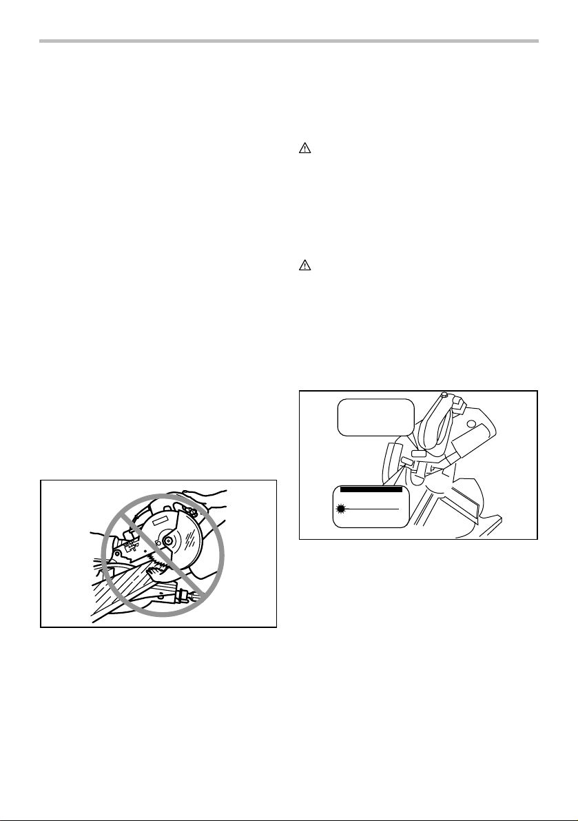
CAUTION:
• LASER RADIATION DO NOT STARE INTO
BEAM.
• AVOID EXPOSURE - LASER RADIATION IS
EMITTED FROM APERTURE.
• USE OF CONTROLS OR ADJUSTMENTS OR
PERFORMANCE OF PROCEDURES OTHER
THAN THOSE SPECIFIED HEREIN MAY
RESULT IN HAZARDOUS RADIATION
EXPOSURE.
Complies with 21CFR
1040.10 and 1040.11
AVOID EXPOSURE-Laser
radiation is emitted from
this aperture
CAUTION
LASER RADIATION
DO NOT STARE INTO BEAM
Maximum Output
<1mW,Wavelength:655nm
CLASS II LASER PRODUCT
000189
5
USB088-1
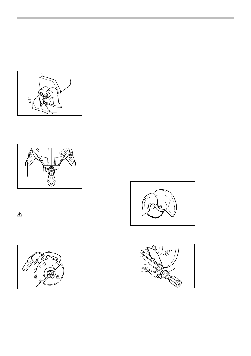
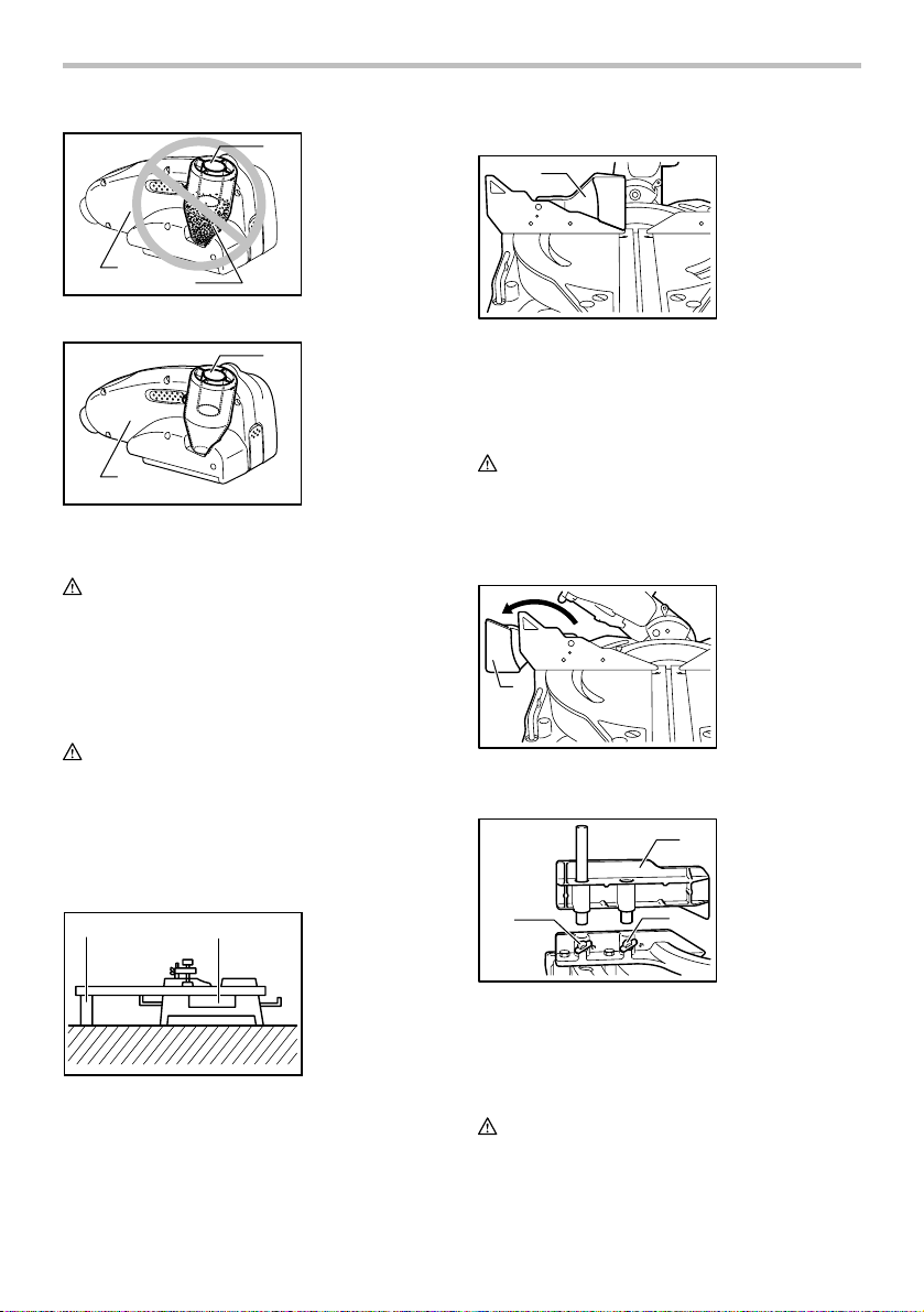
INSTALLATION
Bench mounting
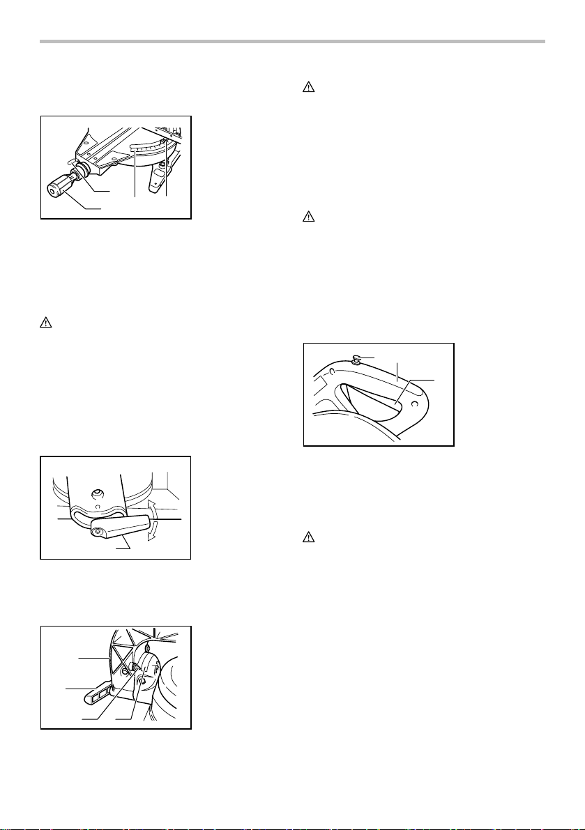
When the tool is shipped, the handle is locked in the
lowered position by the stopper pin. Release the stopper
pin by lowering the handle slightly and pulling the
stopper pin.
1. Stopper pin
1
001564
This tool should be bolted with four bolts to a level and
stable surface using the bolt holes provided in the tool's
base. This will help prevent tipping and possible injury.
1
001531
1. Bolt
FUNCTIONAL DESCRIPTION
CAUTION:
• Always be sure that the tool is switched off and
unplugged before adjusting or checking function on
the tool.
Blade guard
1. Blade guard
GUARD.
In the interest of your personal safety, always maintain
the blade guard in good condition. Any irregular
operation of the blade guard should be corrected
immediately. Check to assure spring loaded return
action of guard. NEVER USE THE TOOL IF THE
BLADE GUARD OR SPRING ARE DAMAGED, FAULTY
OR REMOVED. DOING SO IS HIGHLY DANGEROUS
AND CAN CAUSE SERIOUS PERSONAL INJURY.
If the see-through blade guard becomes dirty, or
sawdust adheres to it in such a way that the blade
and/or workpiece is no longer easily visible, unplug the
saw and clean the guard carefully with a damp cloth. Do
not use solvents or any petroleum-based cleaners on
the plastic guard.
If the blade guard is especially dirty and vision through
the guard is impaired, use the supplied socket wrench to
loosen the hex bolt holding the center cover. Loosen the
hex bolt by turning it counterclockwise and raise the
blade guard and center cover. With the blade guard so
positioned, cleaning can be more completely and
efficiently accomplished. When cleaning is complete,
reverse procedure above and secure bolt. Do not
remove spring holding blade guard. If guard becomes
discolored through age or UV light exposure, contact a
Makita service center for a new guard. DO NOT
DEFEAT OR REMOVE GUARD.
1. Blade guard
1
001782
Positioning kerf board
1. Knob
2. Kerf board
1
002016
When lowering the handle, the blade guard rises
automatically. The blade guard returns to its original
position when the cut is completed and the handle is
raised. NEVER DEFEAT OR REMOVE THE BLADE
GUARD OR THE SPRING WHICH ATTACHES TO THE
6
001537
1
2
1
2
3
4
1. Saw blade
2. Blade teeth
3. Kerf board
4. Left bevel cut
5. Straight cut
6. Right bevel cut
5
6
001538
This tool is provided with the kerf boards in the turn base
to minimize tearing on the exit side of a cut. The kerf
boards are factory adjusted so that the saw blade does
not contact the kerf boards. Before use, adjust the kerf
boards as follows:
First, unplug the tool. Loosen all the screws (2 each on
left and right) securing the kerf boards. Re-tighten them
only to the extent that the kerf boards can still be easily
moved by hand. Lower the handle fully and push in the
stopper pin to lock the handle in the lowered position.
Loosen the knob which secures the slide poles. Pull the
carriage toward you fully. Adjust the kerf boards so that
the kerf boards just contact the sides of the blade teeth.
Tighten the front screws (do not tighten firmly). Push the
carriage toward the guide fence fully and adjust the kerf
boards so that the kerf boards just contact the sides of
blade teeth. Tighten the rear screws (do not tighten
firmly).
After adjusting the kerf boards, release the stopper pin
and raise the handle. Then tighten all the screws
securely.
CAUTION:
• Before and after changing the bevel angle, always
adjust the kerf boards as described above.
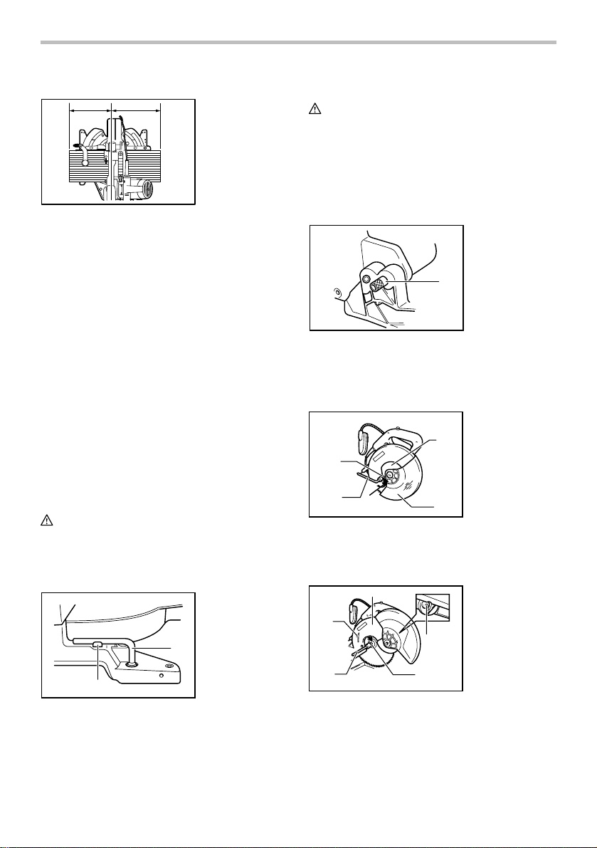
Maintaining maximum cutting capacity
This tool is factory adjusted to provide the maximum
cutting capacity for a 305 mm (12") saw blade.
When installing a new blade, always check the lower
limit position of the blade and if necessary, adjust it as
follows:
1. Adjusting bolt
2. Turn base
1
2
004066
2
1
001540
1. Top surface of
turn base
2. Periphery of
blade
3. Guide fence
3
First, unplug the tool. Push the carriage toward the guide
fence fully and lower the handle completely. Use the
socket wrench to turn the adjusting bolt until the
periphery of the blade extends slightly below the top
surface of the turn base at the point where the front face
of the guide fence meets the top surface of the turn
base.
With the tool unplugged, rotate the blade by hand while
holding the handle all the way down to be sure that the
blade does not contact any part of the lower base.
Re-adjust slightly, if necessary.
CAUTION:
• After installing a new blade, always be sure that
the blade does not contact any part of the lower
base when the handle is lowered completely.
Always do this with the tool unplugged.
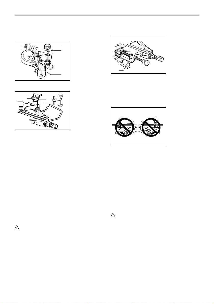
Stopper arm
1. Adjusting screw
1
2. Stopper arm
2
001562
The lower limit position of the blade can be easily
adjusted with the stopper arm. To adjust it, rotate the
stopper arm in the direction of the arrow as shown in the
figure. Adjust the adjusting screw so that the blade stops
7
at the desired position when lowering the handle fully.
Adjusting the miter angle
1. Lock lever
2. Grip
3. Pointer
4. Miter scale
1
2
001541
3
4
Loosen the grip by turning counterclockwise. Turn the
turn base while pressing down the lock lever. When you
have moved the grip to the position where the pointer
points to the desired angle on the miter scale, securely
tighten the grip clockwise.
CAUTION:
• When turning the turn base, be sure to raise the
handle fully.
• After changing the miter angle, always secure the
turn base by tightening the grip firmly.
Adjusting the bevel angle
To adjust the bevel angle, loosen the lever at the rear of
the tool counterclockwise. Unlock the arm by pushing
the handle somewhat strongly in the direction that you
intend to tilt the saw blade.
1. Lever
004056
1
Tilt the saw blade until the pointer points to the desired
angle on the bevel scale. Then tighten the lever
clockwise firmly to secure the arm.
1
2
3 4
001543
1. Arm
2. Lever
3. Pointer
4. Bevel scale
CAUTION:
• When tilting the saw blade, be sure to raise the
handle fully.
• After changing the bevel angle, always secure the
arm by tightening the lever clockwise.
• When changing bevel angles, be sure to position
the kerf boards appropriately as explained in the
"Positioning kerf boards" section.
Switch action
CAUTION:
• Before plugging in the tool, always check to see
that the switch trigger actuates properly and
returns to the "OFF" position when released.
• When not using the tool, remove the lock-off button
and store it in a secure place. This prevents
unauthorized operation.
• Do not pull the switch trigger hard without pressing
in the lock-off button. This can cause switch
breakage.
1. Lock-off button
2. Handle
3. Switch trigger
3
001551
1
2
To prevent the switch trigger from being accidentally
pulled, a lock-off button is provided. To start the tool,
press in the lock-off button and pull the switch trigger.
Release the switch trigger to stop.
WARNING:
• NEVER use tool without a fully operative switch
trigger. Any tool with an inoperative switch is
HIGHLY DANGEROUS and must be repaired
before further usage.
• For your safety, this tool is equipped with a lock-off
button which prevents the tool from unintended
starting. NEVER use the tool if it runs when you
simply pull the switch trigger without pressing the
lock-off button. Return tool to a Makita service
center for proper repairs BEFORE further usage.
• NEVER tape down or defeat purpose and function
of lock-off button.
Electric brake
This tool is equipped with an electric blade brake. If the
tool consistently fails to quickly stop blade after switch
trigger release, have tool serviced at a Makita service
center.
8
The blade brake system is not a substitute for blade
guard. NEVER USE TOOL WITHOUT A FUNCTIONING
BLADE GUARD. SERIOUS PERSONAL INJURY CAN
RESULT.
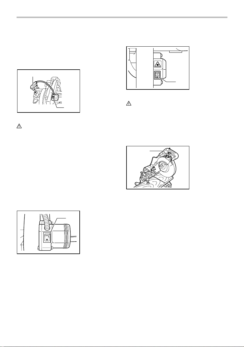
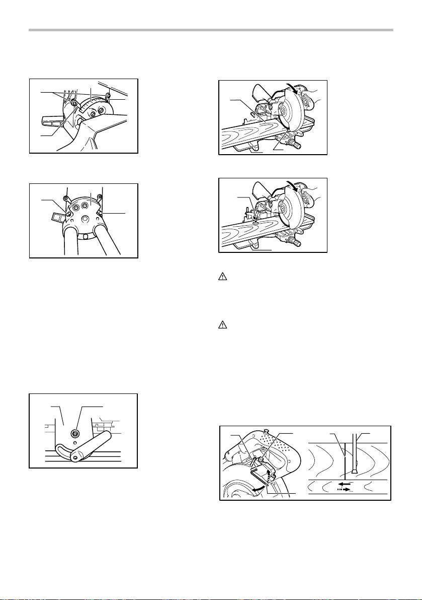
Lighting up the lamps
For Model LS1214F/LS1214FL only
1
2
002026
1. Light
2. Light switch
CAUTION:
• This is not a rainproof light. Do not wash the light in
water or use it in a rain or a wet area. Such a
conduct can cause an electric shock and fume.
• Do not touch the lens of the light, as it is very hot
while it is lighted or shortly after it is turned off. This
may cause a burn to a human body.
• Do not apply impact to the light, which may cause
damage or shorted service time to it.
• Do not keep casting the beam of the light to your
eyes. This can cause your eyes to be hurt.
• Do not cover the light with clothes, carton,
cardboard or similar objects while it is lighted,
which can cause a fire or an ignition.
Push the upper position of the switch for turning on the
light and the lower position for off.
1. Light switch
1
003826
Move the light to shift an area of lighting.
NOTE:
• Use a dry cloth to wipe the dirt off the lens of lamp.
Be careful not to scratch the lens of light, or it may
lower the illumination.
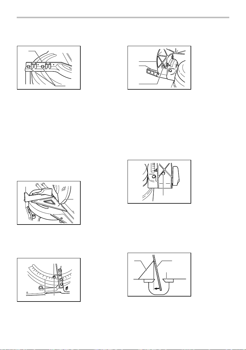
Laser beam action
For model LS1214L/LS1214FL only
1. Switch for laser
1
006339
CAUTION:
• LASER RADIATION
Do not stare into beam.
To turn on the laser beam, press the upper position (I) of
the switch. Press the lower position (O) to turn off.
Laser line can be shifted to either the left or right side of
the saw blade by adjusting the adjusting screw as
follows.
1
006340
1. Loosen the adjusting screw by turning it
counterclockwise.
2. With the adjusting screw loosened, slide the
adjusting screw to the right or left as far as it goes.
3. Tighten the adjusting screw firmly at the position
where it stops sliding.
Laser line is factory adjusted so that it is positioned
within 1 mm (0.04") from the side surface of the blade
(cutting position).
NOTE:
• When laser line is dim and almost or entirely
invisible because of the direct sunlight in the indoor
or outdoor window-by work, relocate the work area
to a place not exposed to the direct sunlight.
9
1. Adjusting screw
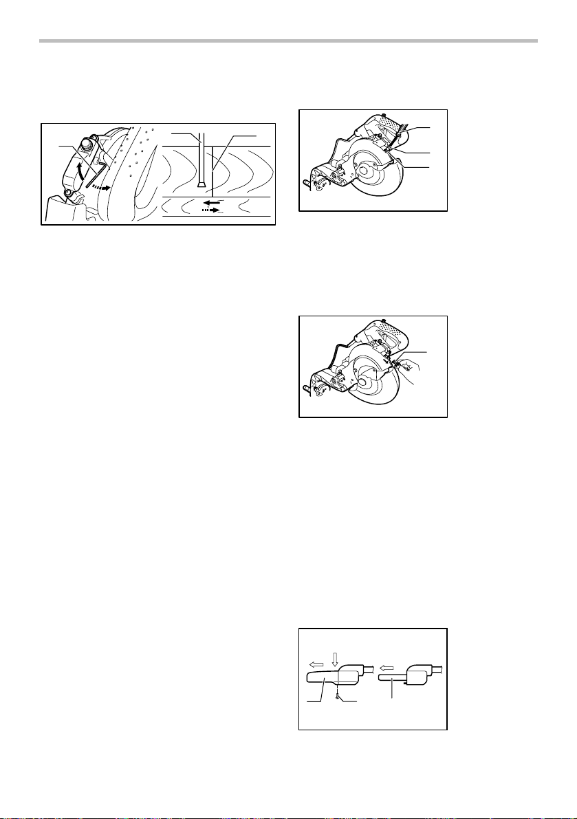
Aligning the laser line
A
006341
B
Laser line can be shifted to either the left or right side of
the blade according to the applications of cutting. Refer
to explanation titled "Laser beam action" regarding its
shifting method.
NOTE:
• Use wood facing against the guide fence when
aligning the cutting line with the laser line at the
side of guide fence in compound cutting (bevel
angle 45 degrees and miter angle right 45
degrees).
A) When you obtain correct size on the left side of
workpiece
• Shift the laser line to the left of the blade.
B) When you obtain correct size on the right side of
workpiece
• Shift the laser line to the right of the blade.
Align the cutting line on your workpiece with the laser
line.
ASSEMBLY
CAUTION:
• Always be sure that the tool is switched off and
unplugged before carrying out any work on the
tool.
Socket wrench storage
1. Socket wrench
2. Wrench holder
1
Installing or removing saw blade
CAUTION:
• Always be sure that the tool is switched off and
unplugged before installing or removing the blade.
• Use only the Makita socket wrench provided to
install or remove the blade. Failure to do so may
result in overtightening or insufficient tightening of
the hex bolt. This could cause an injury.
Lock the handle in the raised position by pushing in the
stopper pin.
1. Stopper pin
1
001564
To remove the blade, use the socket wrench to loosen
the hex bolt holding the center cover by turning it
counterclockwise. Raise the blade guard and center
cover.
1. Center cover
2. Hex bolt
1
3. Socket wrench
2
3
002019
4. Blade guard
4
Press the shaft lock to lock the spindle and use the
socket wrench to loosen the hex bolt clockwise. Then
remove the hex bolt, outer flange and blade.
1
2
3
1. Blade case
2. Arrow
3. Shaft lock
4. Hex bolt
5. Socket wrench
2
001530
The socket wrench is stored as shown in the figure.
When using the socket wrench, pull it out of the wrench
holder. After using the socket wrench, return it to the
wrench holder.
5
002020
4
To install the blade, mount it carefully onto the spindle,
making sure that the direction of the arrow on the
surface of the blade matches the direction of the arrow
on the blade case.
Install the outer flange and hex bolt, and then use the
10
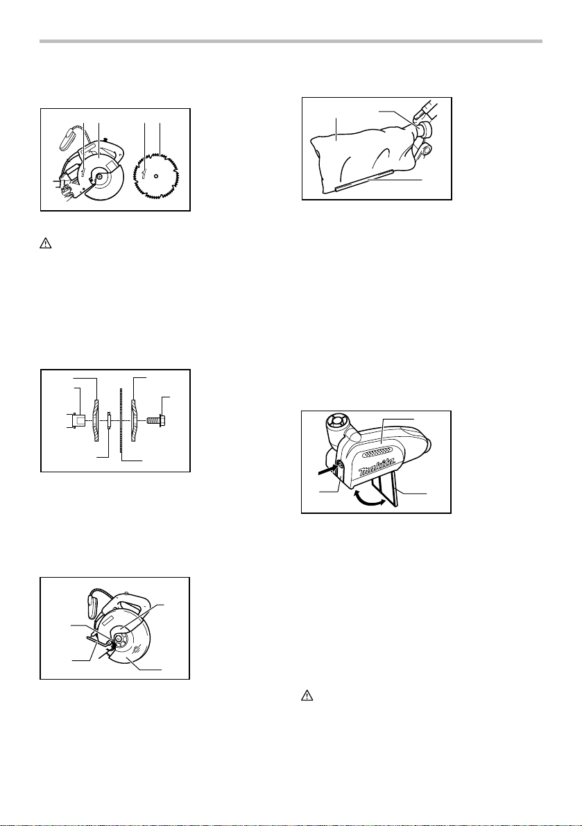
socket wrench to tighten the hex bolt (left-handed)
securely counterclockwise while pressing the shaft lock.
2 1 4 3
002021
CAUTION:
• The black ring 25 mm in outer diameter and the
silver ring 25.4 mm in outer diameter are
factory-installed as shown in the figure. When
using a blade with 25 mm hole diameter, replace
the silver ring with the black ring. Before mounting
the blade onto the spindle, always be sure that the
correct ring for the arbor hole of the blade you
intend to use is installed between the inner and
outer flanges.
1
2
3
004058
Return the blade guard and center cover to its original
position. Then tighten the hex bolt clockwise to secure
the center cover. Release the handle from the raised
position by pulling the stopper pin. Lower the handle to
make sure that the blade guard moves properly. Make
sure shaft lock has released spindle before making cut.
2
3
002019
5
4
1. Blade case
2. Arrow
3. Saw blade
4. Arrow
1. Inner flange
2. Spindle
6
3. Ring
4. Saw blade
5. Outer flange
6. Hex bolt
(left-handed)
1. Center cover
2. Hex bolt
1
3. Socket wrench
4. Blade guard
4
Dust bag (accessory)
1
2
001536
The use of the dust bag makes cutting operations clean
and dust collection easy. To attach the dust bag, insert
the dust nozzle into the dust spout on the blade case
and fit the bag's entry port over the dust nozzle.
When the dust bag is about half full, remove the dust
bag from the tool and pull the fastener out. Empty the
dust bag of its contents, tapping it lightly so as to remove
particles adhering to the insides which might hamper
further collection.
NOTE:
If you connect a vacuum cleaner to your saw, more
efficient and cleaner operations can be performed.
1. Dust nozzle
2. Dust bag
3. Fastener
3
Dust box (accessory)
1. Dust box
1
2. Cover
3. Button
3
006793
Insert the dust box into the dust nozzle.
Empty the dust box at the earliest possible.
To empty the dust box, open the cover by pushing the
button and throw away sawdust. Return the cover to the
original position and it locks. Dust box can easily be
removed by pulling out while turning it near the dust
nozzle on the tool.
NOTE:
• If you connect a Makita vacuum cleaner to this tool,
more efficient and cleaner operations can be
performed.
CAUTION:
• Empty the dust box before collected sawdust level
reaches the cylinder part.
2
11
1. Cylinder part
1
2. Dust box
3. Sawdust
2
006792
006794
Securing workpiece
WARNING:
• It is extremely important to always secure the
workpiece properly and tightly with the vise. Failure
to do so can cause the tool to be damaged and/or
the workpiece to be destroyed. PERSONAL
INJURY MAY ALSO RESULT. Also, after a cutting
operation, DO NOT raise the blade until the blade
has come to a complete stop.
CAUTION:
• When cutting long workpieces, use supports that
are as high as the top surface level of the turn base.
Do not rely solely on the vertical vise and/or
horizontal vise to secure the workpiece.
Thin material tends to sag. Support workpiece over
its entire length to avoid blade pinch and possible
KICKBACK.
1
3
2
2
1. Cylinder part
1
2. Dust box
1. Support
2. Turn base
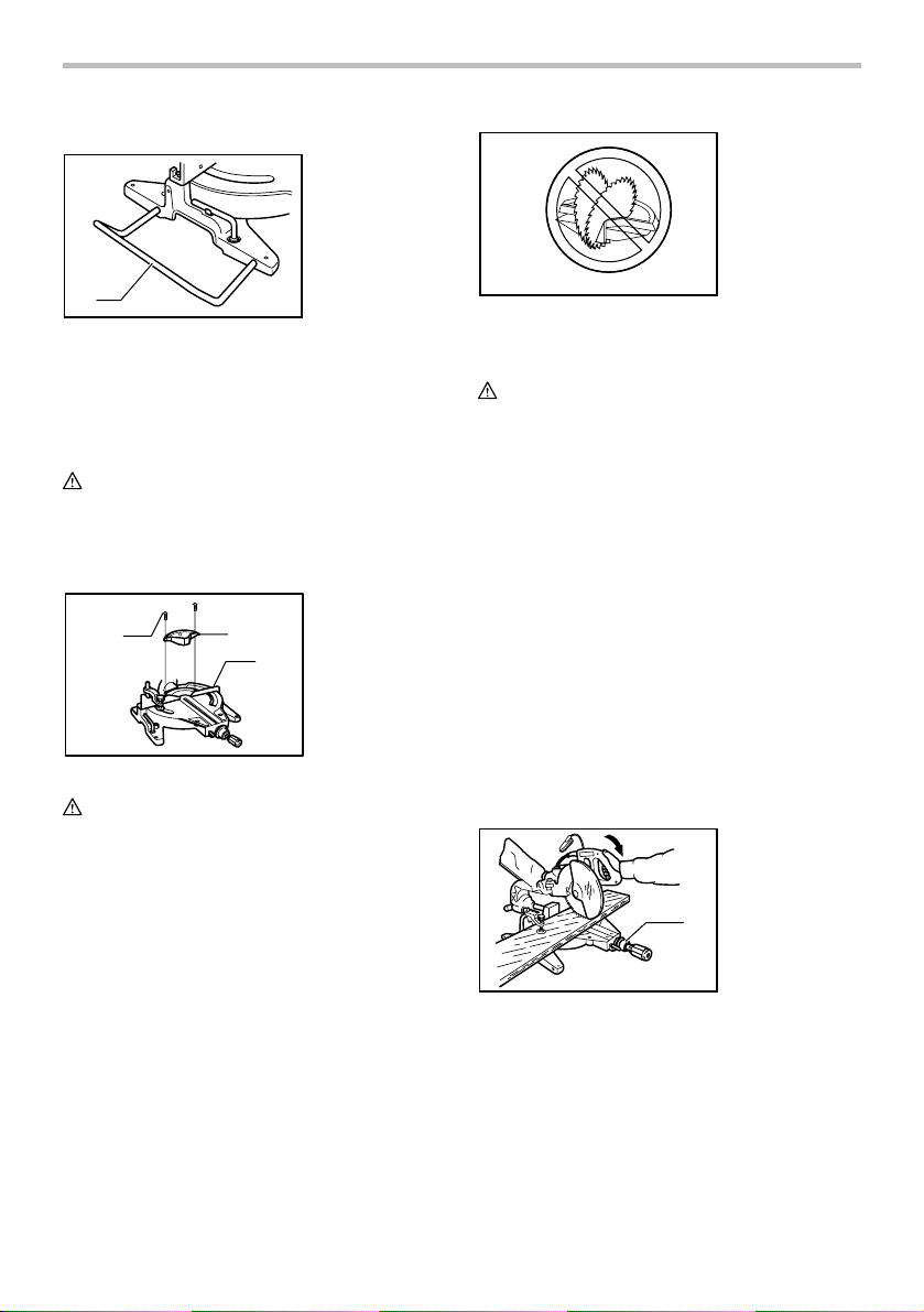
Sub-fence
1
005593
This tool is equipped with the sub-fence which should
ordinarily be positioned as shown in the figure.
However, when performing left bevel cuts, set it to the
left position as shown in the figure.
CAUTION:
• When performing left bevel cuts, flip the fence over
to the left position as shown in the figure.
Otherwise, it will contact the blade or a part of the
tool, causing possible serious injury to the
operator.
1
005594
1. Sub-fence
1. Sub-fence
Sub-fence R
1. Sub-fence R
1
2. Screws
22
001549
005595
The sub-fence R can be installed on the right side of the
guide fence. Insert the rods of the sub-fence R into the
holes in the guide fence. Tighten the screws which come
with the sub-fence R to secure the sub-fence R.
CAUTION:
• When performing right bevel cuts, never use the
sub-fence R. It will contact the blade or a part of
the tool, causing possible serious injury to the
12
operator.
Vertical vise
1
2
1. Vise rod
3
2. Screw
4
3. Vise knob
4. Vise arm
5. Guide fence
Horizontal vise (optional accessory)
1
1. Vise plate
2. Vise nut
3. Vise knob
5
005597
3
2
1
005688
The vertical vise can be installed in two positions on
either the left or right side of the guide fence. Insert the
vise rod into the hole in the guide fence and tighten the
screw on the back of the guide fence to secure the vise
rod.
The vertical vise can also be secured to the rod on the
right side of the sub-fence R.
Position the vise arm according to the thickness and
shape of the workpiece and secure the vise arm by
tightening the screw. If the screw to secure the vise arm
contacts the guide fence, install the screw on the
opposite side of vise arm. Make sure that no part of the
tool contacts the vise when lowering the handle fully and
pulling or pushing the carriage all the way. If some part
contacts the vise, re-position the vise.
Press the workpiece flat against the guide fence and the
turn base. Position the workpiece at the desired cutting
position and secure it firmly by tightening the vise knob.
CAUTION:
• The workpiece must be secured firmly against the
turn base and guide fence with the vise during all
operations.
5
4
1. Sub-fence R
2. Screw
3. Rod
4. Vise rod
5. Vise arm
2 3
001550
The horizontal vise can be installed in two positions on
either the left or right side of the base. When performing
15° or greater miter cuts, install the horizontal vise on
the side opposite the direction in which the turn base is
to be turned.
005232
By flipping the vise nut to the left, the vise is released,
and rapidly moves in and out. To grip the workpiece,
push the vise knob forward until the vise plate contacts
the workpiece and flip the vise nut to the right. Then turn
the vise knob clockwise to secure the workpiece.
The maximum width of workpiece which can be secured
by the horizontal vise is 200 mm (7-7/8").
When installing the horizontal vise on the right side of
the base, also use the sub-fence R to secure the
workpiece more firmly. Refer to the "Sub-fence R"
section described on previously for installing the
sub-fence R.
CAUTION:
• Always rotate the vise nut to the right fully when
securing the workpiece. Failure to do so may result
in insufficient securing of the workpiece. This could
cause the workpiece to be thrown, cause damage
to the blade or cause the loss of control, which can
result in PERSONAL INJURY.
13
Holders
1. Holder
1
001544
The holders can be installed on either side as a
convenient means of holding workpieces horizontally.
Slip the holder rods into the holes in the base and adjust
their length according to the workpiece to be held. Then
tighten the holders securely with the screws.
CAUTION:
• Always support long workpieces level with the top
surface of the turn base for accurate cuts and to
prevent dangerous loss of control of the tool.
Kerf block (optional accessory)
1. Screw
1
004861
2
CAUTION:
• When using the kerf block, always cut at the same
miter angle.
• When changing the miter angle, use other kerf
blocks.
• When performing bevel cuts, never use the kerf
block.
Failure to do so splits the block, causing a serious injury
to operator.
When you use the kerf block at 90° cutting, you can
splinter-free cut in workpiece on the side of the guide
fence (height of the workpiece is up to 35 mm). Install
the kerf block onto the guide fence by means of the two
screws. (Adjust the guide fence and the kerf block so
that they contact their faces. Then tighten the screws
securely.)
2. Kerf block
3. Guide fence
3
005598
OPERATION
CAUTION:
• Before use, be sure to release the handle from the
lowered position by pulling the stopper pin.
• Make sure the blade is not contacting the
workpiece, etc. before the switch is turned on.
• Do not apply excessive pressure on the handle
when cutting. Too much force may result in
overload of the motor and/or decreased cutting
efficiency. Push down handle with only as much
force as is necessary for smooth cutting and
without significant decrease in blade speed.
• Gently press down the handle to perform the cut. If
the handle is pressed down with force or if lateral
force is applied, the blade will vibrate and leave a
mark (saw mark) in the workpiece and the
precision of the cut will be impaired.
• During a slide cut, gently push the carriage toward
the guide fence without stopping. If the carriage
movement is stopped during the cut, a mark will be
left in the workpiece and the precision of the cut
will be impaired.
1. Press cutting (cutting small workpieces)
1. Knob
1
002022
Workpieces up to 115 mm (4-1/2") high and 75 mm
(2-15/16") wide can be cut in the following way.
Push the carriage toward the guide fence fully and
tighten the knob clockwise to secure the carriage.
Secure the workpiece with the vise. Switch on the
tool without the blade making any contact and wait
until the blade attains full speed before lowering.
Then gently lower the handle to the fully lowered
position to cut the workpiece. When the cut is
14

completed, switch off the tool and WAIT UNTIL
THE BLADE HAS COME TO A COMPLETE STOP
before returning the blade to its fully elevated
position.
CAUTION:
• Firmly tighten the knob clockwise so that the
carriage will not move during operation. Insufficient
tightening may cause unexpected kickback of the
blade. Possible serious PERSONAL INJURY may
result.
2. Slide (push) cutting (cutting wide workpieces)
1. Knob
1
002023
Loosen the knob counterclockwise so that the
carriage can slide freely. Secure the workpiece
with the vise. Pull the carriage toward you fully.
Switch on the tool without the blade making any
contact and wait until the blade attains full speed.
Press down the handle and PUSH THE
CARRIAGE TOWARD THE GUIDE FENCE AND
THROUGH THE WORKPIECE. When the cut is
completed, switch off the tool and WAIT UNTIL
THE BLADE HAS COME TO A COMPLETE STOP
before returning the blade to its fully elevated
position.
CAUTION:
• Whenever performing the slide cut, FIRST PULL
THE CARRIAGE TOWARD YOU FULLY and press
down the handle to the fully lowered position, then
PUSH THE CARRIAGE TOWARD THE GUIDE
FENCE. NEVER START THE CUT WITH THE
CARRIAGE NOT FULLY PULLED TOWARD YOU.
If you perform the slide cut without pulling the
carriage fully or if you perform the slide cut toward
your direction, the blade may kickback
unexpectedly with the potential to cause serious
PERSONAL INJURY.
• Never perform the slide cut with the handle locked
in the lowered position by pressing the stopper pin.
• Never loosen the knob which secures the carriage
while the blade is rotating. This may cause serious
injury.
3. Miter cutting
Refer to the previously covered "Adjusting the
miter angle".
4. Bevel cut
002024
Loosen the lever and tilt the saw blade to set the
bevel angle (Refer to the previously covered
"Adjusting the bevel angle"). Be sure to retighten
the lever firmly to secure the selected bevel angle
safely. Secure the workpiece with a vise. Make
sure the carriage is pulled all the way back toward
the operator. Switch on the tool without the blade
making any contact and wait until the blade attains
full speed. Then gently lower the handle to the fully
lowered position while applying pressure in parallel
with the blade and PUSH THE CARRIAGE
TOWARD THE GUIDE FENCE TO CUT THE
WORKPIECE. When the cut is completed, switch
off the tool and WAIT UNTIL THE BLADE HAS
COME TO A COMPLETE STOP before returning
the blade to its fully elevated position.
CAUTION:
• Always be sure that the blade will move down to
bevel direction during a bevel cut. Keep hands out
of path of saw blade.
• During a bevel cut, it may create a condition
whereby the piece cut off will come to rest against
the side of the blade. If the blade is raised while the
blade is still rotating, this piece may be caught by
the blade, causing fragments to be scattered which
is dangerous. The blade should be raised ONLY
after the blade has come to a complete stop.
• When pressing down the handle, apply pressure in
parallel with the blade. If a force is applied
perpendicularly to the turn base or if the pressure
direction is changed during a cut, the precision of
the cut will be impaired.
• Always set the sub-fence to the left position when
performing left bevel cuts.
5. Compound cutting
Compound cutting is the process in which a bevel
angle is made at the same time in which a miter
angle is being cut on a workpiece. Compound
cutting can be performed at angle shown in the
15
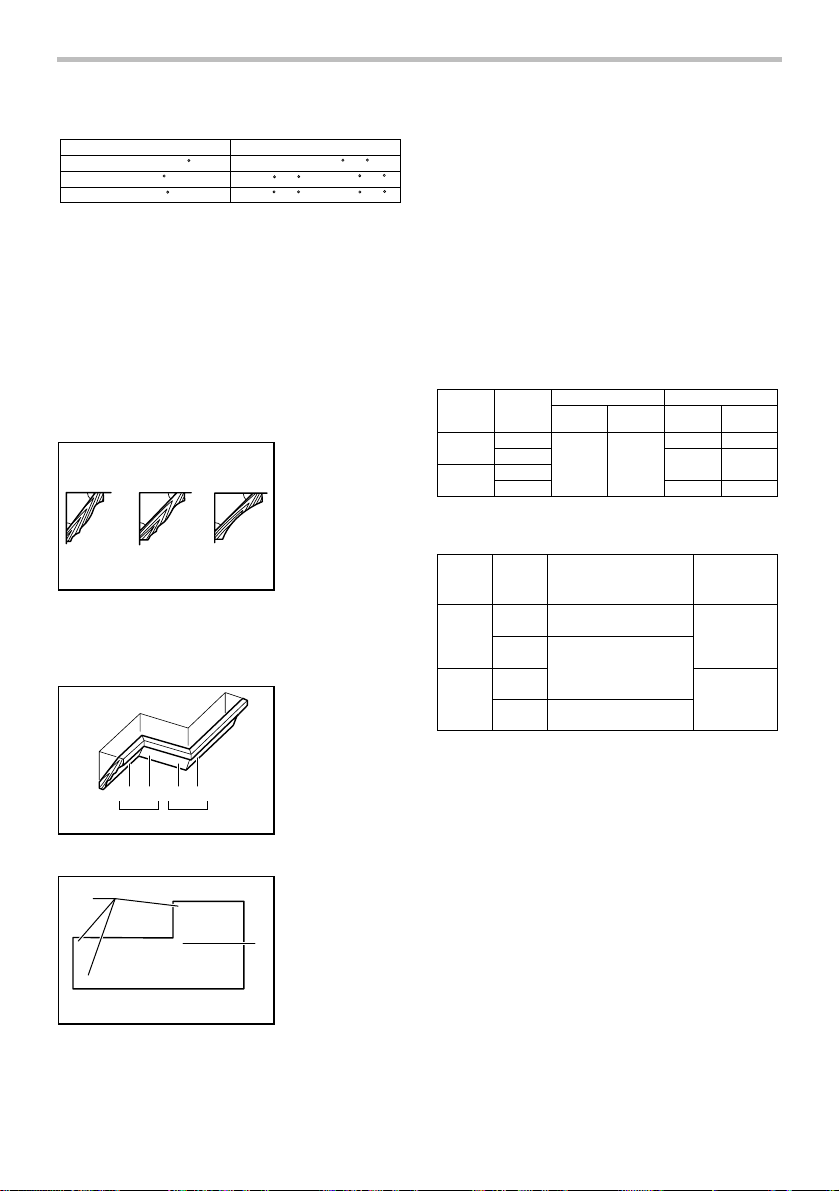
table.
006484
Miter angle
Left and Right 45
Left 47
Right 52
Bevel angle
Left and Right 0 - 45
Left 0 - 45 and Right 0 - 40
Left 0 - 30 and Right 0 - 45
When performing compound cutting, refer to
"Press cutting", "Slide cutting", "Miter cutting" and
"Bevel cut" explanations.
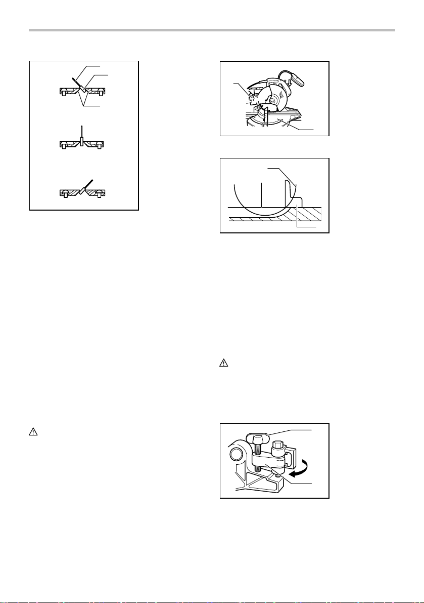
6. Cutting crown and cove moldings
Crown and cove moldings can be cut on a
compound miter saw with the moldings laid flat on
the turn base.
There are two common types of crown moldings
and one type of cove moldings; 52/38° wall angle
crown molding, 45° wall angle crown molding and
45° wall angle cove molding. See illustrations.
1. 52/38 ゚ type
crown molding
52
38
45
45
45
45
2. 45 ゚ type crown
molding
3. 45 ゚ type cove
molding
123
001555
There are crown and cove molding joints which are
made to fit "Inside" 90° corners ((1) and (2) in Fig.
A) and "Outside" 90° corners ((3) and (4) in Fig. A).
1. Inside corner
2. Outside corner
(1) (2) (3)(4)
Fig.A
001556
1 2
1. Inside corner
2. Outside corner
(1)
(2)
2
(1)
(2)
(1)
(2)
001557
1
(2)
(1)
(2)
(1)
(4)
(3)
Measuring
Measure the wall length and adjust workpiece on
table to cut wall contact edge to desired length.
Always make sure that cut workpiece length at the
back of the workpiece is the same as wall length.
Adjust cut length for angle of cut. Always use
several pieces for test cuts to check the saw
angles.
When cutting crown and cove moldings, set the
bevel angle and miter angle as indicated in the
table (A) and position the moldings on the top
surface of the saw base as indicated in the table
(B).
In the case of left bevel cut
Molding
position in
Fig. A
For inside
corner
For outside
corner
006361
(1)
(2)
(3)
(4)
Molding
position in
Fig. A
For inside
corner
For
outside
corner
006362
(1)
(2)
(3)
(4)
Example:
In the case of cutting 52/38° type crown
molding for position (1) in Fig. A:
• Tilt and secure bevel angle setting to
33.9° LEFT.
• Adjust and secure miter angle setting to
31.6° RIGHT.
• Lay crown molding with its broad back
(hidden) surface down on the turn base
with its CEILING CONTACT EDGE
against the guide fence on the saw.
• The finished piece to be used will
always be on the LEFT side of the blade
after the cut has been made.
Table (A)
Bevel angleMiter angle
52/38° type 45° type
Left 33.9° Left 30°
52/38° type
Right 31.6°
Left 31.6° Left 35.3°
Table (B)
Molding edge against
guide fence
Ceiling contact edge should
be against guide fence.
Wall contact edge should be
against guide fence
Ceiling contact edge should
be against guide fence
.
.
45° type
Right 35.3°
Right 35.3°Right 31.6°
Finished piece
Finished piece
will be on the
Left side of
blade.
Finished piece
will be on the
Right side of
blade.
16

In the case of right bevel cut
Table (A)
Bevel angleMiter angle
52/38° type 45° type
Right 33.9° Right 30°
For inside
corner
For outside
corner
006363
Molding
position in
Fig. A
(1)
(2)
(3)
(4)
Table (B)
Molding
Molding edge against
position in
guide fence
Fig. A
Wall contact edge should be
(1)
agains
For inside
corner
For
outside
corner
006364
(2)
(3)
(4)
t guide fence.
Ceiling contact edge should
be against guide fence.
Wall contact edge should be
against guide fence.
52/38° type
Right 31.6°
45° type
Right 35.3°
Left 31.6° Left 35.3°
Right 35.3°Right 31.6°
Finished piece
Finished piece
will be on the
Right side of
blade.
Finished piece
will be on the
Left side of
blade.
Example:
In the case of cutting 52/38° type crown
molding for position (1) in Fig. A:
• Tilt and secure bevel angle setting to
33.9° RIGHT.
• Adjust and secure miter angle setting to
31.6° RIGHT.
• Lay crown molding with its broad back
(hidden) surface down on the turn base
with its WALL CONTACT EDGE against
the guide fence on the saw.
• The finished piece to be used will
always be on the RIGHT side of the
blade after the cut has been made.
17
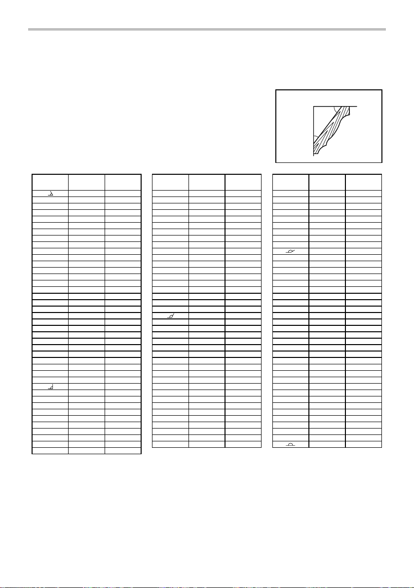
Compound Miter Saw
Miter and Bevel Angle Settings
Ceiling
52°
38°
Wall
Wall to Crown Molding Angle: 52/38 degrees
Wall Angle
(deg.)
EN0002-1
Bevel Angle
60
61
62
63
64
65
66
67
68
69
70
71
72
73
74
75
76
77
78
79
80
81
82
83
84
85
86
87
88
89
90
91
92
93
94
95
96
97
98
99
100
(deg.)
43.0
42.8
42.5
42.2
41.9
41.7
41.4
41.1
40.8
40.5
40.2
39.9
39.6
39.3
39.0
38.7
38.4
38.1
37.8
37.4
37.1
36.8
36.5
36.2
35.8
35.5
35.2
34.9
34.5
34.2
33.9
33.5
33.2
.8
32
32.5
32.2
31.8
31.5
31.1
30.8
30.4
Miter Angle
(deg.)
46.8
46.3
45.7
45.1
44.6
44.0
43.5
42.9
42.4
41.9
41.3
40.8
40.3
39.8
39.2
38.7
38.2
37.7
37.2
36.8
36.3
35.8
35.3
34.8
34.4
33.9
33.4
.0
33
32.5
32.1
31.6
31.2
30.7
30.3
29.9
29.4
29.0
28.6
28.2
27.7
27.3
Wall Angle
(deg.)
Bevel Angle
101
102
103
104
105
106
107
108
109
110
111
112
113
114
115
116
117
118
119
120
121
122
123
124
125
126
127
128
129
130
131
132
133
134
135
36
1
137
138
139
140
(deg.)
30.1
29.7
29.4
29.0
28.7
28.3
28.0
27.6
27.2
26.9
26.5
26.1
25.8
25.4
25.0
24.7
24.3
23.9
23.6
23.2
22.8
22.5
22.1
21.7
21.3
21.0
20.6
20.2
19.8
19.5
19.1
18.7
18.3
17.9
7.6
1
17.2
16.8
16.4
16.0
15.6
Miter Angle
(deg.)
26.9
26.5
26.1
25.7
25.3
24.9
24.5
24.1
23.7
23.3
22.9
22.6
22.2
21.8
21.4
21.0
20.7
20.3
19.9
19.6
19.2
18.8
18.5
18.1
17.8
17.4
17.1
16.7
16.4
16.0
15.7
15.3
5.0
1
14.6
14.3
14.0
13.6
13.3
13.0
12.8
000031
Wall Angle
(deg.)
141
142
143
144
145
146
147
148
149
150
151
152
153
154
155
156
157
158
159
160
161
162
163
164
165
166
167
168
169
170
171
172
173
174
175
176
177
178
179
180
Bevel Angle
(deg.)
15.3
14.9
14.5
14.1
13.7
13.3
12.9
12.5
12.2
11.8
11.4
11. 0
10.8
10.2
9.8
9.4
9.0
8.6
8.3
7.9
7.5
7.1
6.7
6.3
5.9
5.5
5.1
4.7
4.3
3.9
3.5
3.2
2.8
2.4
2.0
1.6
1.2
0.8
0.4
0.0
Miter Angle
(deg.)
12.3
12.0
11.6
11. 3
11. 0
10.7
10.3
10.0
9.7
9.4
9.0
8.7
8.4
8.1
7.8
7.5
7.1
6.8
6.5
6.2
5.9
5.6
5.3
4.9
4.6
4.3
4.0
3.7
3.4
3.1
2.8
2.5
2.2
1.8
1.5
1.2
0.9
0.6
.3
0
0.0
18
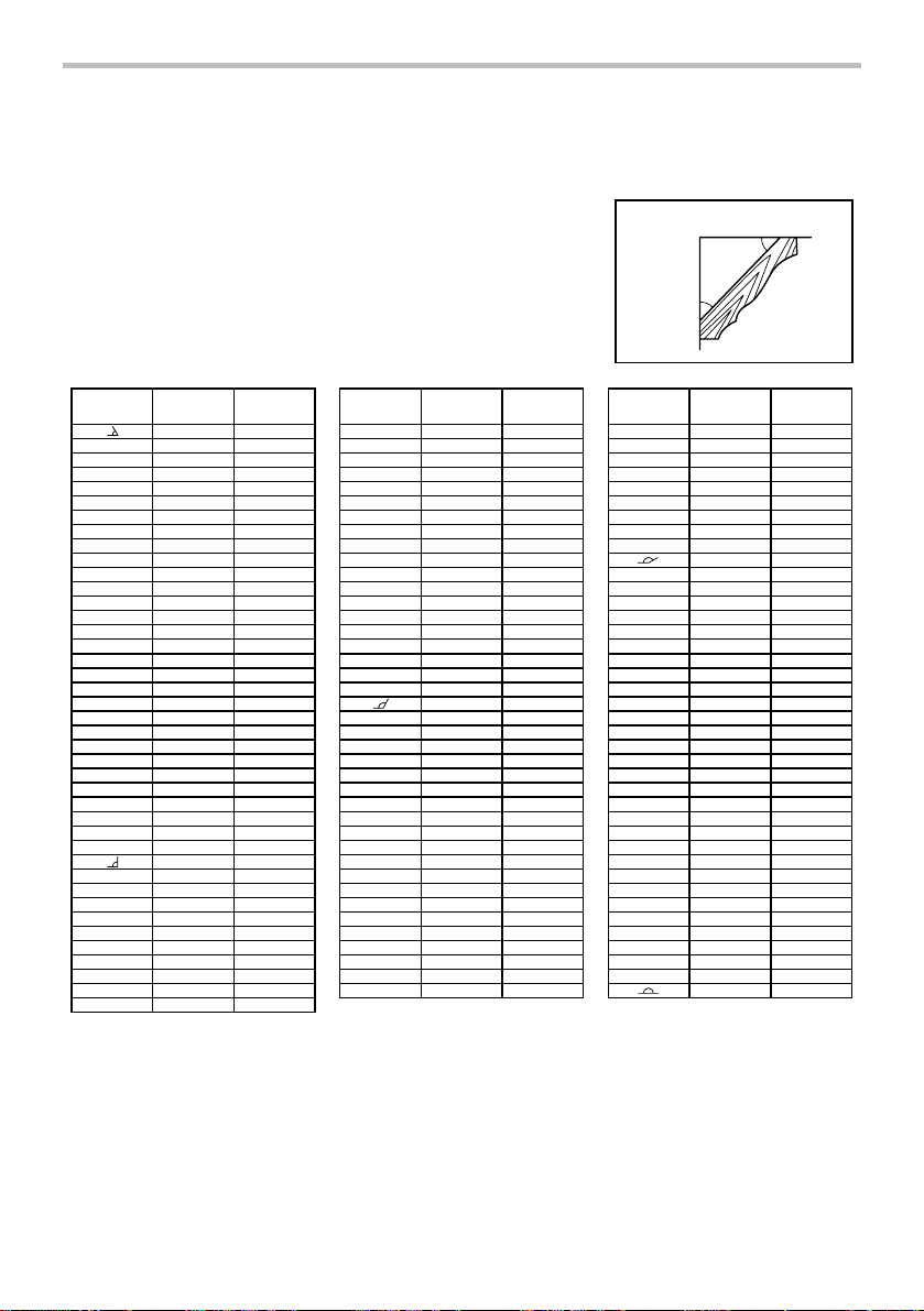
Compound Miter Saw
Miter and Bevel Angle Settings
Ceiling
45°
45°
Wall
Wall to Crown Molding Angle: 45 degrees
Wall Angle
EN0003-1
(deg.)
Bevel Angle
60
61
62
63
64
65
66
67
68
69
70
71
72
73
74
75
76
77
78
79
80
81
82
83
84
85
86
87
88
89
90
91
92
93
94
95
96
97
98
99
100
(deg.)
37.8
37.5
37.3
37.1
36.8
36.6
36.4
36.1
35.9
35.6
35.4
35.1
34.9
34.6
34.4
34.1
33.9
33.6
33.3
33.1
32.8
32.5
32.3
32.0
31.7
31.4
31.1
30.9
30.6
30.3
30.0
29.7
29.4
29.1
28.8
28.5
28.2
27.9
27.6
27.3
27.0
Miter Angle
(deg.)
50.8
50.2
49.6
49.1
48.5
48.0
47.4
46.9
46.4
45.8
45.3
44.8
44.2
43.7
43.2
42.7
42.1
41.6
41.1
40.6
40.1
39.6
39.1
38.6
38.1
37.7
37.2
36.7
36.2
35.7
35.3
34.8
34.3
33.9
33.4
32.9
32.5
32.0
31.6
31.1
30.7
Wall Angle
(deg.)
Crown molding stoppers (optional accessories)
allow easier cuts of crown molding without tilting
the saw blade. Install them on the turn base as
shown in the figures.
Bevel Angle
101
102
103
104
105
106
107
108
109
110
111
112
113
114
115
116
117
118
119
120
121
122
123
124
125
126
127
128
129
130
131
132
133
134
135
136
137
138
139
140
(deg.)
26.7
26.4
26.1
25.8
25.5
25.2
24.9
24.6
24.2
23.9
23.6
23.3
23.0
22.7
22.3
22.0
21.7
21.4
21.0
20.7
20.4
20.0
19.7
19.4
19.1
18.7
18.4
18.1
17.7
17.4
17.1
16.7
16.4
16.0
15.7
15.4
15.0
14.7
14.3
14.0
Miter Angle
(deg.)
30.2
29.8
29.4
28.9
28.5
28.1
27.6
27.2
26.8
26.3
25.9
25.5
25.1
24.7
24.3
23.8
23.4
23.0
22.6
22.2
21.8
21.4
21.0
20.6
20.2
19.8
19.4
19.0
18.6
18.2
17.9
17.5
17.1
16.7
16.3
15.9
15.6
15.2
14.8
14.4
000032
Wall Angle
(deg.)
141
142
143
144
145
146
147
148
149
150
151
152
153
154
155
156
157
158
159
160
161
162
163
164
165
166
167
168
169
170
171
172
173
174
175
176
177
178
179
180
Bevel Angle
(deg.)
13.7
13.3
13.0
12.6
12.3
11. 9
11. 6
11. 2
10.9
10.5
10.2
9.8
9.5
9.2
8.8
8.5
8.1
7.8
7.4
7.1
6.7
6.4
6.0
5.6
5.3
4.9
4.6
4.2
3.9
3.5
3.2
2.8
2.5
2.1
1.8
1.4
1.1
0.7
0.4
0.0
Miter Angle
(deg.)
14.1
13.7
13.3
12.9
12.6
12.2
11. 8
11. 5
11. 1
0.7
1
10.4
10.0
9.6
9.3
8.9
8.5
8.2
7.8
7.5
7.1
6.7
6.4
6.0
5.7
5.3
5.0
4.6
4.3
3.9
3.5
3.2
2.8
2.5
2.1
1.8
1.4
1.1
0.7
0.4
0.0
19
1 2
3
001558
1. Crown molding
stopper L
2. Crown molding
stopper R
3. Turn base
1 2
3
001559
1. Crown molding
stopper L
2. Crown molding
stopper R
3. Turn base
Fig. B: At right 45° miter angle
Fig. C: At left 45° miter angle
Position crown molding with its WALL CONTACT
EDGE against the guide fence and its CEILING
CONTACT EDGE against the crown molding
stoppers as shown in the figure. Adjust the crown
molding stoppers according to the size of the
crown molding. Tighten the screws to secure the
crown molding stoppers. Refer to the table (C) for
the miter angle. Use the sub-fence R to secure the
crown molding more firmly.
1. Guide fence
2. Crown molding
3. Crown molding
stopper
4. Screw
1
001560
2
3 4
Table (C)
Position in
Miter angle Finished piece
Fig. A
For i
corner
For outside
corner
006365
(1) Right 45°Save the right side of blade
nside
(2)Save the left side of blade
Left 45°
(3)Save the right side of blade
(4) Right 45°Save the left side of blade
1. Cutting aluminum extrusion
1. Vise
1
2
3
2. Spacer block
3. Guide fence
4. Aluminum
extrusion
5. Spacer block
4
5
001844
1
3
2
1. Aluminum
extrusion
2. Guide fence
3. Spacer blocks
4. Horizontal vise
(optional
accessory)
4
004073
When securing aluminum extrusions, use spacer
blocks or pieces of scrap as shown in the figure to
prevent deformation of the aluminum. Use a
cutting lubricant when cutting the aluminum
extrusion to prevent build-up of the aluminum
material on the blade.
CAUTION:
• Never attempt to cut thick or round aluminum
extrusions. Thick aluminum extrusions may come
loose during operation and round aluminum
extrusions cannot be secured firmly with this tool.
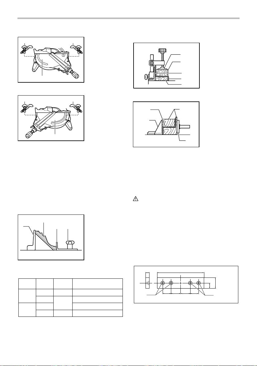
2. Wood facing
Use of wood facing helps to assure splinter-free
cuts in workpieces. Attach a wood facing to the
guide fence using the holes in the guide fence and
6 mm (1/4") screws.
See the figure concerning the dimensions for a
suggested wood facing.
Over 15mm (9/16") Over 540mm (21-1/4")
72mm
(2-13/16")
20mm (13/16")
1. Hole
005233
1
72mm
120mm
(4-3/4")
120mm
(4-3/4")
(2-13/16")
20
115mm-120mm
(4-1/2" - 4-3/4")
1
CAUTION:
• Use straight wood of even thickness as the wood
facing.
• When cutting workpieces from 115 mm (4 -1/2") to
120 mm (4 - 3/4") high, use a wood facing to
prevent a portion of the workpiece near the guide
fence from being left uncut.
Example:
When cutting workpieces 120 mm (4 - 3/4")
high, use a wood facing with the following
thickness.
Miter angle Thickness of wood facing
0 Over 20 mm (13/16")
Left and Right 45 Over 15 mm (9/16")
Right 52 Over 15 mm (9/16")
006475
CAUTION:
• Use screws to attach the wood facing to the guide
fence. The screws should be installed so that the
screw heads are below the surface of the wood
facing.
• When the wood facing is attached, do not turn the
turn base with the handle lowered. The blade
and/or the wood facing will be damaged.
3. Groove cutting
1
1. Cut grooves with
blade
CAUTION:
• Be sure to return the stopper arm to the original
position when performing other than groove
cutting.
Carrying tool
1. Stopper pin
1
001564
Make sure that the tool is unplugged. Secure the blade
at 0° bevel angle and the turn base at right miter angle
fully. Secure the slide poles after pulling the carriage
toward you fully. Lower the handle fully and lock it in the
lowered position by pushing in the stopper pin.
Carry the tool by holding both sides of the tool base as
shown in the figure. If you remove the holders, dust bag,
etc., you can carry the tool more easily.
001563
A dado type cut can be made by proceeding as
follows:
Adjust the lower limit position of the blade using
the adjusting screw and the stopper arm to limit the
cutting depth of the blade. Refer to "Stopper arm"
section described previously.
After adjusting the lower limit position of the blade,
cut parallel grooves across the width of the
workpiece using a slide (push) cut as shown in the
figure. Then remove the workpiece material
between the grooves with a chisel. Do not attempt
to perform this type of cut using wide (thick) blades
or with a dado blade. Possible loss of control and
injury may result.
002025
CAUTION:
• Always secure all moving portions before carrying
the tool.
• Stopper pin is for carrying and storage purposes
only and not for any cutting operations.
MAINTENANCE
CAUTION:
• Always be sure that the tool is switched off and
unplugged before attempting to perform inspection
or maintenance.
WARNING:
• Always be sure that the blade is sharp and clean
for the best and safest performance.
Adjusting the cutting angle
This tool is carefully adjusted and aligned at the factory,
but rough handling may have affected the alignment. If
21
your tool is not aligned properly, perform the following:
1. Miter angle
1
1. Guide fence
2. Hex bolts
2. Bevel angle
(1) 0° bevel angle
1
2
1. Arm
2. Lever
3. Hex bolt
2
001566
Push the carriage toward the guide fence and
tighten the knob to secure the carriage.
Loosen the grip which secures the turn base. Turn
the turn base so that the pointer points to 0° on the
miter scale. Then turn the turn base slightly
clockwise and counterclockwise to seat the turn
base in the 0° miter notch. (Leave as it is if the
pointer does not point to 0°.) Loosen the hex bolts
securing the guide fence using the socket wrench.
Lower the handle fully and lock it in the lowered
position by pushing in the stopper pin. Square the
side of the blade with the face of the guide fence
using a triangular rule, try-square, etc. Then
securely tighten the hex bolts on the guide fence in
the order from the right side.
1
001567
Make sure that the pointer points to 0° on the miter
scale. If the pointer does not point to 0°, loosen the
screw which secures the pointer and adjust the
pointer so that it will point to 0°.
1
1. Guide fence
2. Triangular rule
2
1. Screw
2. Miter scale
3. Pointer
3
001569
Push the carriage toward the guide fence and
tighten the knob to secure the carriage.
Lower the handle fully and lock it in the
lowered position by pushing in the stopper
pin. Loosen the lever at the rear of the tool.
Make sure that the arm is locked.
Turn the hex bolt on the left side of the arm
two or three revolutions counterclockwise.
Turn the hex bolt on the right side of the arm
two or three revolutions counterclockwise to
tilt the blade to the left.
1
001570
Carefully square the side of the blade with
the top surface of the turn base using the
triangular rule, try-square, etc. by turning the
hex bolt on the right side of the arm clockwise.
Turn the hex bolt on the left side of the arm
clockwise as far as it will go. Then tighten the
lever securely.
1 2
1. Hex bolt
1. Triangular rule
2. Saw blade
3. Top surface of
3
turn base
001568
32
001571
Make sure that the two pointers on the arm
point to each 0° on the bevel scale on the
arm holder. If they do not point to 0°, loosen
22
the screws which secure the pointers and
adjust them so that they will point to 0°.
2
3
001572
(2) 45° bevel angle
2
001573
Adjust the 45° bevel angle only after
performing 0° bevel angle adjustment. To
adjust left 45° bevel angle, loosen the lever
and tilt the blade to the left fully. Make sure
that the pointer on the arm points to 45° on
the bevel scale on the arm holder. If the
pointer does not point to 45°, turn the left 45°
bevel angle adjusting bolt on the side of the
arm holder until the pointer points to 45°.
To adjust right 45° bevel angle, perform the
same procedure described above.
1
1
1. Bevel scale
2. Screws
3
3. Pointers
1. Arm holder
2. Right 45 ゚ bevel
angle adjusting
bolt
3
3. Left 45 ゚ bevel
angle adjusting
bolt
Adjusting for smooth beveling action
1
2
1. Arm
2. Hex lock nut
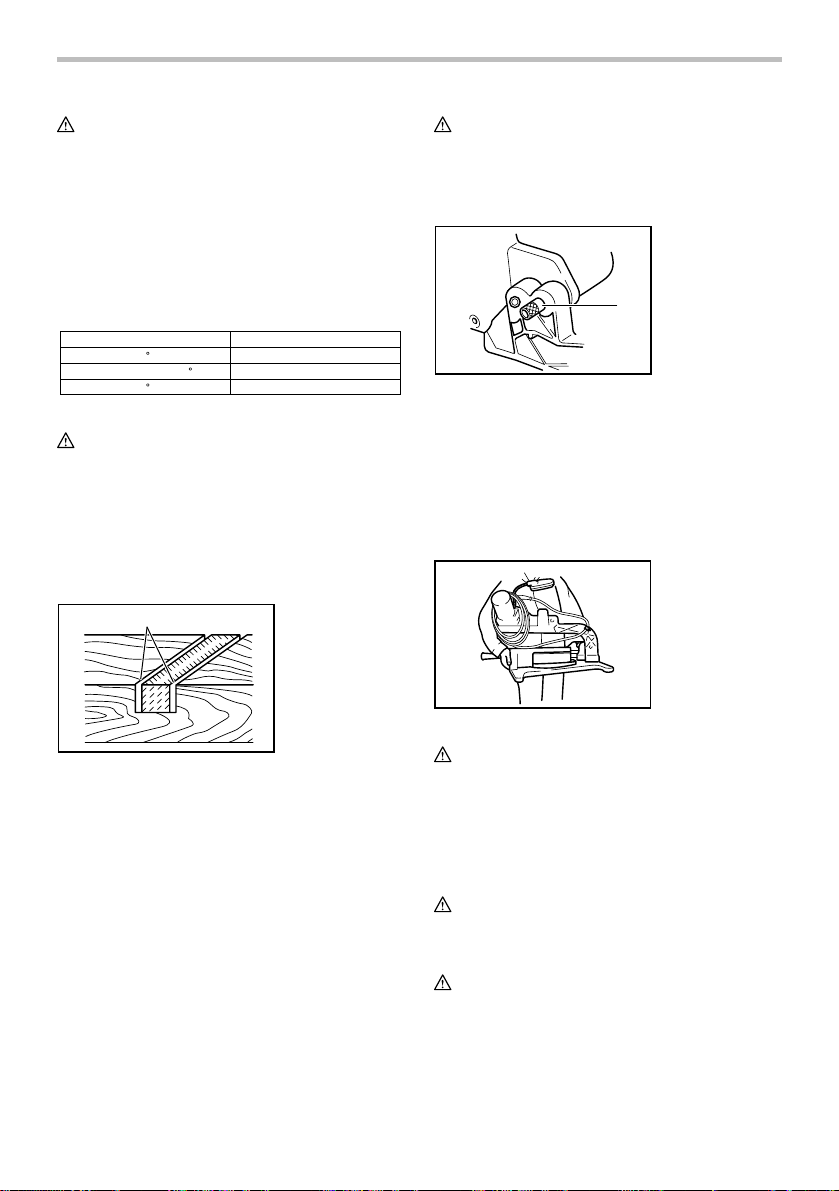
Adjusting the position of laser line
For model LS1214L/LS1214FL only
1. Workpiece
1
2
006342
1
006343
WARNING:
• As the tool is plugged when adjusting the position
CAUTION:
• Never look into the laser beam directly. Direct laser
• LASER RADIATION
• Never apply a blow or impact to the tool. A blow or
When adjusting the laser line appears on the left
side of the saw blade
1
3
2
of laser line, take a full caution especially at switch
action. Pulling the switch trigger accidentally cause
an accidental start of the tool and personal injury.
beam causes damage to your eyes.
Do not stare into beam.
impact causes the incorrect position of laser line,
damage to the laser beam emitting part or a short
life of the tool.
2
2. Cutting line
3. Holder
1. Vertical vise
2. Holder
4
5
004860
The hex lock nut holding together the arm and arm
holder has been factory adjusted to assure smooth
beveling action and to guarantee precise cutting. Do not
tamper with it. Should looseness develop at the arm and
arm holder connection, tighten the hex lock nut using a
wrench.
3
1. Screw to change the movable range of the adjusting
screw
2. Adjusting screw
3. Hex Wrench
4. Laser line
5. Saw blade
006345
23
When adjusting the laser line appears on the right
side of the saw blade
2
1
Cleaning of the lens for the laser light
For model LS1214L/LS1214FL only
3
1. Screwdriver
1
2. Screw (one
3. Lens for the
2
3
piece only)
laser light
1. Screw to change the movable range of the adjusting
screw
2. Saw blade
3. Laser line
006344
For both adjustments, do as follows.
1. Make sure that the tool is unplugged.
2. Draw the cutting line on the workpiece and place it
on the turn table. At this time, do not secure the
workpiece with a vise or similar securing device.
3. Lower the blade by lowering the handle and just
check to see where the cutting line and the
position of the saw blade is. (Decide which
position to cut on the line of cut.)
4. After decision the position to be cut, return the
handle to the original position. Secure the
workpiece with the vertical vise without shifting
the workpiece from the pre-checked position.
5. Plug the tool and turn on the laser switch.
6. Adjust the position of laser line as follows.
The position of laser line can be changed as the
movable range of the adjusting screw for the laser is
changed by turning two screws with a hex wrench. (The
movable range of laser line is factory adjusted within 1
mm (0.04") from the side surface of blade.)
To shift the laser line movable range further away from
the side surface of blade, turn the two screws
counterclockwise after loosening the adjusting screw.
Turn these two screws clockwise to shift it closer to the
side surface of the blade after loosening the adjusting
screw.
Refer to the section titled "Laser line action" and adjust
the adjusting screw so that the cutting line on your
workpiece is aligned with the laser line.
NOTE:
• Check the position of laser line regularly for
accuracy .
• Have the tool repaired by Makita authorized
service center for any failure on the laser unit.
006346
If the lens for the laser light becomes dirty, or sawdust
adheres to it in such a way that the laser line is no longer
easily visible, unplug the saw and remove and clean the
lens for the laser light carefully with a damp, soft cloth.
Do not use solvents or any petroleum-based cleaners on
the lens.
1. Lens for the
laser light
1
006347
To remove the lens for the laser light, remove the saw
blade before removing the lens according to the
instructions in the section titled "Installing or removing
saw blade".
Loosen but do not remove the screw which secures the
lens using a screwdriver.
Pull out the lens as shown in the figure.
NOTE:
• If the lens does not come out, loosen the screw
further and pull out the lens again without removing
the screw.
Replacing fluorescent tube
For LS1214F/LS1214FL only
1. Pull out
2. Push
3. Lamp box
4. Screws
5. Fluorescent tube
24
3
002028
2
1
1
4
5
 Loading...