

Makita LS1211 Instruction Manual
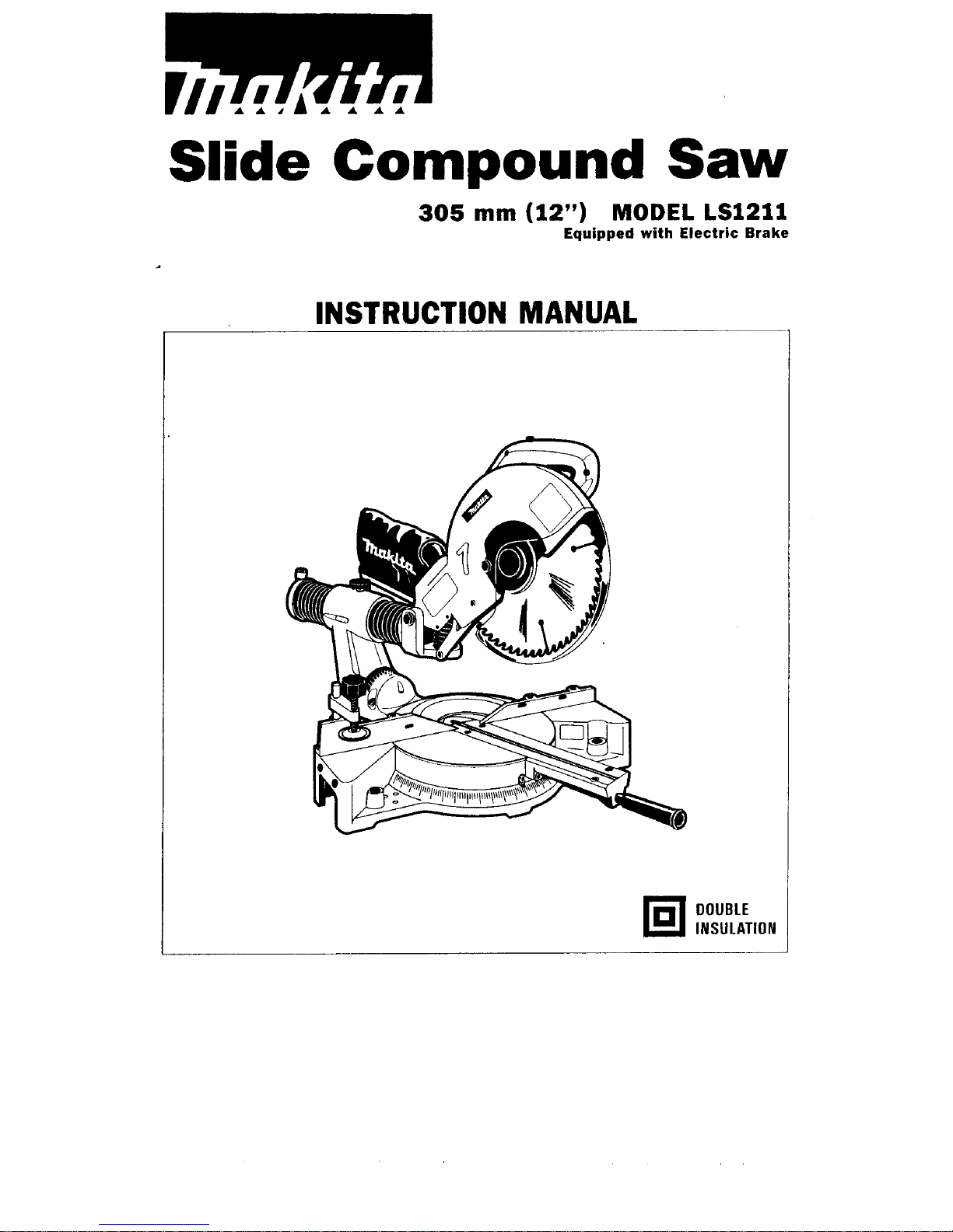
Slide
Compound
Saw
305
mm
(12”)
MODEL
LSl21l
Equipped with Electric Brake
INSTRUCTION MANUAL
DOUBLE
INSULATION
SPECIFICATIONS
Blade diameter ..............................................................................................................
305
mm
11
2")
Arbor diameter ..............................................................................................................
25.4
mm
11")
Max cutting capacities
1H x W)
Left and right
45O
Bevel angle
Left
45"
Right
45"
I
Miter angle
21
mm
113/16"1
.
65
mm
x
230
mm
12-9/16" x 9-1/16',)
57
mm
x
290
mm
12-1/4" x 11-7/16")
48
mm
x
310
mm
11-7/8" x 12-3/16")
00
.
65
mm
x
162
mm
12-9/16'' X 6-3/8"1
57
mm
x
205
mm
(2-1/4" x 8-1/16',)
Left and right
45O
48
mm
x
219
mm
1
.11-7/8" x 8-5/8")
49
mm
x
230
mm
*11-15/16" x 9-1/16',)
40
mm
x
290
mm
11-9/16" x 11-7/16")
31
mm
x
310
mm
11-1/4" x 12-3/16")
49
mm
x
162
mm
40
mm
x
205
mm
11-9/16" x 8-1/16',)
31
mm
x
219
mm
11-1/4"
x
8-5/8")
11-15/16" x 6-3/8"1
[Note)
mark indicates that a wood facing with the following thickness is used.
Miter angle
I
Thickness of wood facing
I
I
30
mm
11-3/16',)
I
oo
00
.120
mm
x
230
mm
14-3/4" x 9-1/16',)
107
mm
x
290
mm
14-3/16" x 11-7/16")
94
mm
x
310
mm
13-11/16" x 12-3/16")
.120
mm
x
162
mm
(4-3/4" x 6-3/8"1
107
mm
x
205
mm
94
mm
x
219
mm
13-1 1/16" x 8-5/8")
14-3/16"
x
8-1/16")
-120mmx
115mm
(4-3/4"
x
4-112")
107
mm
x
145
mm
14-3/16' x 5-1 1/16',)
94
mm
x
155
mm
13-11/16" x 6-118"l
No
load speed (RPMl
................................................................................................................
4,000
Dimensions (L
x W x
HI
..............................
140-15/16" x 23-13/16" x 24-7/16,')
Net weight
.......................
Manufacturer reserves the right to change specifications without notice.
Note: Specifications may differ from country to country.
WARNING: For your personal safety, READ and UNDERSTAND before using.
SAVE THESE INSTRUCTIONS FOR FUTURE REFERENCE.
.._.
1,040
mm
x
605
mm
x
620
mm
2
For Your Own Safety Read Instruction
Manual Before Operating
Slide Compound Saw
Save
it
for future reference
GENERAL SAFETY PRECAUTIONS
(For
All
Tools)
1.
KNOW YOUR POWER TOOL. Read the owner’s manual carefully. Learn the
tools applications and limitations, as well as the specific potential hazards
peculiar to
it.
2.
KEEP GUARDS IN PLACE and
in
working order.
3.
REMOVE ADJUSTING KEYS AND WRENCHES. Form habit of checking to
see that keys and adjusting wrenches are removed from tool before turning
it
on.
4.
KEEP WORK AREA CLEAN. Cluttered areas and benches invite accidents.
5.
DON’T USE IN DANGEROUS ENVIRONMENT. Don’t use power tools
in
damp
or wet locations, or expose them to rain. Keep work area well lighted.
Don’t use tool
in
presence of flammable liquids or gases.
6.
KEEP CHILDREN AWAY. All visitors should be kept safe distance from work
area.
7.
MAKE WORKSHOP CHILD PROOF
with
padlocks, master switches, or
by
removing starter keys.
8.
DON‘T FORCE TOOL.
It
will do the job better and safer at the rate for which
it
was designed.
9.
USE RIGHT TOOL. Don’t force tool or attachment
to
do a job for which
it
was not designed.
IO.
WEAR PROPER APPAREL. Wear no loose clothing, gloves, neckties, rings,
bracelets, or other jewelry which may get caught
in
moving parts. Nonslip
footwear is recommended. Wear protective hair covering to contain long hair.
11.
ALWAYS USE SAFETY GLASSES. Also use face or dust mask if cutting
operation is dusty. Everyday eyeglasses only have impact resistant lenses,
they are NOT safety glasses.
12.
SECURE WORK. Use clamps or a vise to hold work when practical. It’s safer
than using your hand and
it
frees both hands to operate tool.
13.
DON‘T OVERREACH. Keep proper footing and balance at all times.
14.
MAINTAIN TOOLS WITH CARE. Keep tools sharp and clean for best and
safest performance. Follow instructions for lubricating and changing accessories.
15.
DISCONNECT TOOLS before servicing, when changing accessories such as
blades,
bits,
cutters, and the like.
3
16.
EXTENSION
CORDS.
Make sure your extension cord is in good condition.
When using an extension cord, be sure to use one heavy enough to carry
the current your product will draw. An undersized cord
will
cause a drop
in line voltage resulting in
loss
of
power and overheating. Table 1 shows the
correct size to use depending on cord length and nameplate ampere rating.
If
in doubt, use the next heavier gauge. The smaller the gauge number, the
heavier the cord.
TABLE
1
MINIMUM GAUGE
FOR
CORD
SETS
Total Length
of
Cord
in
Feet
0-
6
6
-
10
10
-
12
12
-
16
I
0
-
25
I
26
-
50
I
51 - 100 I 101
-
150
18 16 14
18 16
16
16 14 12
14
12 Not Recommended
:t
I
12
Ampere Rating
More Not MOW
Than Than
AWG
VOLTAGE WARNING: Before connecting the tool to a power source (receptacle,
outlet, etc.) be sure the voltage supplied is the same as that specified on the
nameplate of the tool. A power source with voltage greater than that specified
for the tool can result in SERIOUS INJURY to the user
-
as well as damage to
the tool. If in doubt, DO NOT PLUG IN THE TOOL. Using a power source with
voltage less than the nameplate rating is harmful to the motor.
ADDITIONAL
SAFETY
RULES
1.
Wear eye protection.
2.
Do
not operate saw without guards
in
place.
3.
Don't use the tool in the presence of flammable liquids or gases.
4.
Check the blade carefully for cracks or damage before operation.
5.
Use only flanges specified for this tool.
6.
Be careful not to damage the arbor, flanges (especially the installing surface)
-
7.
Make sure that the turn base is properly secured
so
it
will not move during
8.
For your safety, remove the chips, small pieces, etc. from the table top before
9.
Avoid cutting nails. Inspect for and remove all nails from the workpiece before
Replace cracked or damaged blade immediately.
or bolt. Damage to these parts could result
in
blade breakage.
operation.
operation.
operation.
IO.
Make sure the shaft lock is released before the switch is turned on.
1
1.
Be sure that the blade does not contact the turn base
in
the lowest position.
12.
Hold the handle firmly. Be aware that the saw moves up or down slightly
during start-up and stopping.
13.
Do not perform any operation freehand. The workpiece must be secured
firmly against the turn base and guide fence with the vise during all
operations. Never use your hand to secure the workpiece.
14.
Keep hands out of path of saw blade. Avoid contact with any coasting blade.
It
can still cause severe injury.
15.
Never reach around saw blade.
16.
Make sure the blade is not contacting
the
workpiece before the switch is
turned on.
17.
Before using the tool on an actual workpiece, let
it
run for a while. Watch
for vibration or wobbling that could indicate poor installation or a poorly
balanced blade.
18.
Wait
until
the blade attains full speed before cutting.
19.
Stop operation immediately if you notice anything abnormal.
20.
Do
not attempt to lock the trigger
in
the on position.
21.
Shut off power and wait for saw blade to stop before servicing or adjusting
tool.
22.
Be alert at all times, especially during repetitive, monotonous operations.
Don't be lulled into a false sense of security. Blades are extremely unforgiving.
23.
Always use accessories recommended in this manual. Use of improper
accessories such as abrasive wheels may cause an injury.
24.
Don't abuse cord. Never yank cord to disconnect
it
from the receptacle. Keep
cord away from heat, oil, water and sharp edges.
SAVE
THESE INSTRUCTIONS.
5
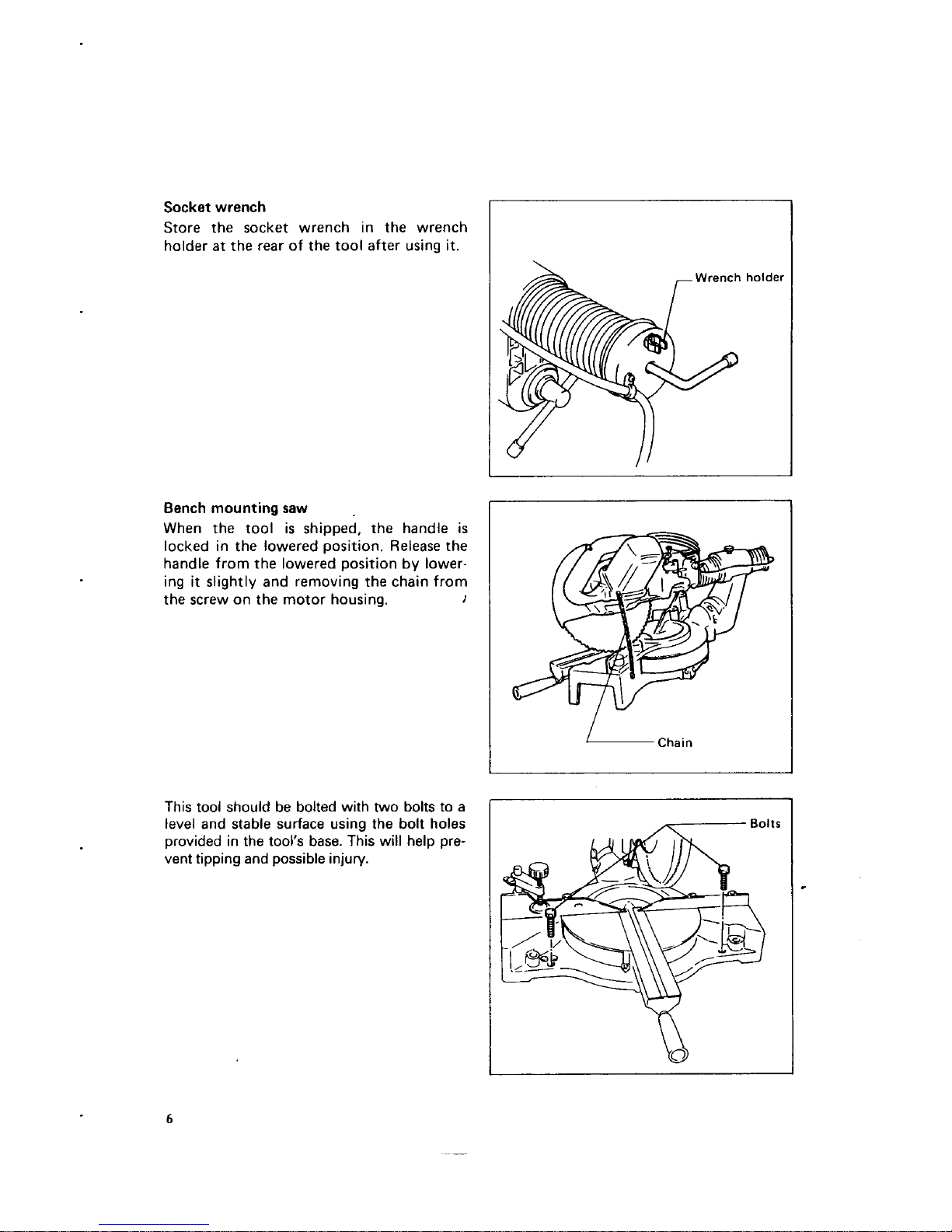
Socket wrench
Store the socket wrench in the wrench
holder
at
the rear of the tool after using
it.
Bench mounting saw
,
When the tool
is
shipped,
the
handle
is
locked in the lowered position. Release the
handle from the lowered position by lowering
it
slightly and removing the chain from
the screw on the motor housing.
I
Wrench holder
1
I
I
Chain
This tool should be bolted with
two
bolts to a
level and stable surface using the bolt holes
provided in the tool’s base. This will help pre-
vent tipping and possible injury.
6

Installing
or
removing
saw
blade
CAUTION
:
Always be sure that the tool
is
switched off and unplugged before installing
or
removing
the blade.
Use the socket wrench to loosen the hex
bolt which secures the center cover
by
turning counterclockwise.
Raise
the safety
cover and the center cover.
Press
the shaft lock to lock the spindle
and use the socket wrench to loosen the
hex bolt by turning it clockwise. Then remove the hex bolt, outer flange and blade.
To
install the blade, mount
it
carefully
onto the spindle, making sure that the
direction of the arrow on the surface of the
blade matches the direction of the arrow
on the blade
case.
Socket wrenc
Hex bolt (left-handed)
Socket wrench
\-Outer
flange
rSpindle
Ring
Inner flange
Saw blade
I--
Hex bolt (left-handed)
7
Install the outer flange and hex bolt, and
then use the socket wrench to tighten the
hex bolt securely by turning
it
counter-
clockwise while pressing the shaft lock.
Return the safety cover and the center
cover to the original position. Then tighten
the hex bolt to secure the center cover.
Lower the handle to make sure that the
safety cover moves properly.
I
/-Safety
cover
I
-Socket
wrench
CAUTION:
Use only the Makita socket wrench provided to install or remove the blade. Failure to do
so
may result in overtightening or insufficient tightening of the hex bolt. This could cause
serious injury to operator or others in the general vicinity of the tool.
Safety cover
When lowering the handle, the safety cover
rises automatically. The cover returns to
its
original position when the cut is complet d
and the handle
is
raised. NEVER DEFE&T
OR
REMOVE THE SAFETY COVER. In
the interest
of
your personal safety, always
maintain the safety cover in good condition.
Any irregular operation of the safety cover
should be corrected immediately. NEVER
USE THE TOOL WITH A FAULTY
SAFETY COVER. If the see-through safety
cover becomes dirty, or sawdust adheres to
it
in sucha way that the blade and/or work-
--
~~
piece is no longer easily visible, unplug the saw and clean the cover carefully with a damp
cloth.
Do
not use solvents or any petroleum-based cleaners on the plastic cover.
Dust
bag
To attach the dust bag,
fit
it into the elbow.
When the dust bag
is
about half full, remove the dust bag from the tool and pull
the fastener out. Empty the dust bag by
tapping
it
lightly to remove
as
much dust
as
possible.
NOTE
:
If
you
connect a vacuum cleaner to your saw, more efficient and cleaner operations can be
performed.
8
Positioning
kerf
boards
This tool
is
provided with kerf boards in the turn base. The kerf boards are factory-adjusted
so
that the saw blade does not contact the kerf boards. Before use, adjust the kerf boards
as
follows:
First unplug the tool. Loosen the
all
screws
(2
each on left and right) which secure the
kerf boards. Retighten them to the extent
that the
kerf boards can be easily moved by
hand. Loosen the clamp screw on the arm.
Pull the carriage toward
you
fully and
lower the handle
fully.
Adjust the kerf
boards
so
that the kerf boards just contact
the sides of blade teeth slightly. Tighten
the front screws (do not tighten firmly).
Push the carriage toward the guide fence
fully and adjust the kerf boards
so
that the
kerf boards just contact the sides of blade teeth slightly. Tighten the rear screws (do not
tighten firmly). After adjusting the kerf boards, tighten the
all
screws securely.
1
Kerf
board
Left
bevel
cut
Straight
cut
Right
bevel
cut
CAUTION:
After changing the bevel angle, always readjust the kerf boards
as
described above.
9
 Loading...