

Page 1
GB Slide Compound Miter Saw Instruction manual
F Scie à onglet radiale Manuel d’instructions
D Kapp- und Gehrungssäge Betriebsanleitung
I Troncatrice radiale per legno Istruzioni per l’uso
NL Schuifbare samengesteld- Gebruiksaanwijzing
verstekzaag
E Sierra de inglete telescópica Manual de instrucciones
P Serra de esquadria c/braço Manual de instruções
telescópico
DK Afkorter- og geringssav Brugsanvisning
GR Συρόμενο σύνθετο φαλτσοπρίονο Οδηγίες χρήσης
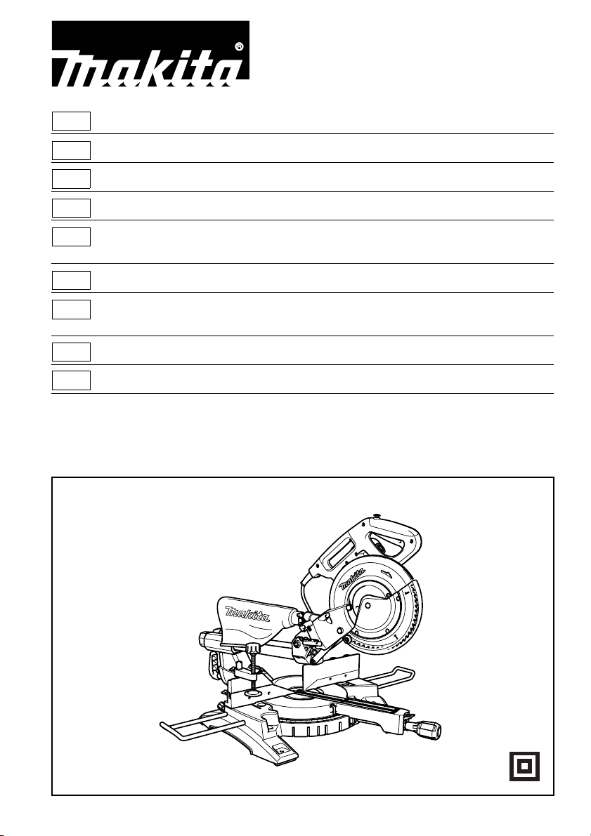
LS1018
LS1018L
Page 2
2
1
2
12
3
3
34
6
7
8
5
4
9
10
4
56
2
Page 3
11
14
13
12
15
78
16
17
18
20
19
21
910
24
22
23
19
22
11 12
22
13 14
19
25
24
3
Page 4
26
15 16
22
27
28
29
27
28
29
17 18
31
19 20
30
34
32
21 22
4
33
Page 5
1
23 24
35
38
36
37
3
36
35
38
39
40
25 26
43
6
45
44
41
42
27 28
47
46
49
35
36
39
39
12
38
6
36
37
3
48
29 30
5
Page 6
50
51
31 32
50
52
53
33 34
57
58
55
35 36
56
5
15
54
55
59
37 38
6
26
Page 7
26
39 40
60 61 62
41 42
(1)
(2)
63
(1)
(2)
(1)
(4)
(3)
(1)
(2)
(2)
64
(1)
(2)
43 44
67
15
66
68
(1) (2) (3)(4)
Fig. A
63 64
15
15 mm Over 500 mm
24 mm
68 mm 121 mm 68 mm
69
121 mm
20 mm
65
66
67
66
80 mm - 90 mm
69
45 46
7
Page 8
70
47 48
38
15
21
49 50
5
19
18
51 52
15
71
22
23
71
72
73
53 54
8
6
13
Page 9
5
19
24
55 56
57 58
74
73
75
76
9
Page 10

ENGLISH
Contents
SPECIFICATIONS ......................................................... 11
ADDITIONAL SAFETY RULES FOR TOOL.................. 12
INSTALLATION ............................................................. 13
FUNCTIONAL DESCRIPTION ......................................13
ASSEMBLY ................................................................... 15
OPERATION.................................................................. 17
MAINTENANCE............................................................. 20
ACCESSORIES............................................................. 21
FRANÇAIS
Table des matières
SPÉCIFICATIONS ......................................................... 22
CONSIGNES DE SÉCURITÉ ADDITIONNELLES
POUR L’OUTIL .............................................................. 23
INSTALLATION ............................................................. 24
DESCRIPTION DU FONCTIONNEMENT ..................... 24
ASSEMBLAGE .............................................................. 27
FONCTIONNEMENT..................................................... 29
ENTRETIEN .................................................................. 32
ACCESSOIRES ............................................................. 33
DEUTSCH
Inhalt
TECHNISCHE DATEN .................................................. 35
ZUSÄTZLICHE SICHERHEITSREGELN FÜR DAS
WERKZEUG .................................................................. 36
INSTALLATION ............................................................. 37
FUNKTIONSBESCHREIBUNG .....................................37
MONTAGE..................................................................... 40
BETRIEB ....................................................................... 43
WARTUNG .................................................................... 46
ZUBEHÖR ..................................................................... 47
ITALIANO
Sommario
CARATTERISTICHE TECNICHE .................................. 49
REGOLE DI SICUREZZA AGGIUNTIVE PER
L’UTENSILE .................................................................. 50
INSTALLAZIONE ........................................................... 51
DESCRIZIONE FUNZIONALE ...................................... 51
MONTAGGIO ................................................................ 54
USO ............................................................................... 56
MANUTENZIONE .......................................................... 59
ACCESSORI.................................................................. 60
NEDERLANDS
Inhoud
TECHNISCHE GEGEVENS ..........................................62
AANVULLENDE VEILIGHEIDSVOORSCHRIFTEN
VOOR GEREEDSCHAP................................................ 63
VOORBEREIDINGEN ................................................... 64
BESCHRIJVING VAN DE FUNCTIES........................... 64
ONDERDELEN AANBRENGEN/VERWIJDEREN ........ 67
GEBRUIK....................................................................... 69
ONDERHOUD ............................................................... 72
ACCESSOIRES ............................................................. 73
ESPAÑOL
Contenido
ESPECIFICACIONES .................................................... 75
NORMAS DE SEGURIDAD ADICIONALES PARA LA
HERRAMIENTA .............................................................76
INSTALACIÓN ...............................................................77
DESCRIPCIÓN DEL FUNCIONAMIENTO ....................77
MONTAJE ......................................................................80
OPERACIÓN..................................................................82
MANTENIMIENTO .........................................................85
ACCESORIOS ...............................................................86
PORTUGUÊS
Índice
ESPECIFICAÇÕES........................................................88
REGRAS ADICIONAIS DE SEGURANÇA PARA A
FERRAMENTA .............................................................. 89
INSTALAÇÃO ................................................................90
DESCRIÇÃO DO FUNCIONAMENTO...........................90
MONTAGEM ..................................................................93
FUNCIONAMENTO .......................................................95
MANUTENÇÃO..............................................................98
ACESSÓRIOS ...............................................................99
DANSK
Indhold
SPECIFIKATIONER..................................................... 101
YDERLIGERE SIKKERHEDSREGLER FOR
MASKINEN .................................................................. 102
MONTERING ...............................................................103
FUNKTIONSBESKRIVELSE........................................103
MONTERING ...............................................................105
BETJENING .................................................................107
VEDLIGEHOLDELSE .................................................. 110
TILBEHØR ...................................................................111
ΕΛΛΗΝΙΚΑ
Περιεχόμενα
ΠΡΟΔΙΑΓΡΑΦΕΣ .........................................................113
ΠΡΟΣΘΕΤΟΙ ΚΑΝΟΝΕΣ ΑΣΦΑΛΕΙΑΣ ΓΙΑ ΤΟ
ΕΡΓΑΛΕΙΟ ................................................................... 114
ΤΟΠΟΘΕΤΗΣΗ ............................................................115
ΠΕΡΙΓΡΑΦΗ ΛΕΙΤΟΥΡΓΙΑΣ
ΣΥΝΑΡΜΟΛΟΓΗΣΗ.....................................................118
ΛΕΙΤΟΥΡΓΙΑ ................................................................121
ΣΥΝΤΗΡΗΣΗ ...............................................................124
ΑΞΕΣΟΥΑΡ..................................................................125
........................................115
10
Page 11

ENGLISH (Original Instructions)
Explanation of general view
1. Stopper pin
2. Bolts
3. Blade guard
4. Kerf board
5. Screw
6. Saw blade
7. Blade teeth
8. Left bevel cut
9. Straight cut
10. Right bevel cut
11. Adjusting bolt
12. Turn base
13. Top surface of turn base
14. Periphery of blade
15. Guide fence
16. Stopper arm
17. Adjusting screw
18. Miter scale
19. Pointer
20. Lock lever
21. Grip
22. Lever
23. Arm
24. Bevel scale
25. Release button
26. Locking screw
27. Lock-off button
28. Switch trigger
29. Hole for padlock
30. Switch for laser
31. Screw holding the laser unit box
32. Dry cell
33. Socket wrench with hex wrench
on its other end
34. Wrench holder
35. Socket wrench
36. Blade case
37. Center cover
38. Hex bolt
39. Arrow
40. Shaft lock
41. Hex bolt (left-handed)
42. Outer flange
43. Ring
44. Inner flange
45. Spindle
46. Dust nozzle
47. Dust bag
48. Fastener
49. Support
50. Sliding fence
51. Clamping screw
52. Sub-fence R
53. Screws
54. Vise arm
55. Vise knob
56. Vise rod
57. Vise plate
58. Vise nut
59. Holder
60. 52/38° type crown molding
61. 45° type crown molding
62. 45° type cove molding
63. Inside corner
64. Outside corner
65. Vise
66. Spacer block
67. Aluminum extrusion
68. Horizontal vise (optional
accessory)
69. Holes
70. Cut grooves with blade
71. Triangular rule
72. 0° adjusting bolt
73. Left 45° bevel angle adjusting bolt
74. Right 45° bevel angle adjusting
bolt
75. Screwdriver
76. Brush holder cap
SPECIFICATIONS
Model LS1018/LS1018L
Blade diameter 255 mm - 260 mm
Hole diameter
For all countries other than European countries 25.4 mm
For European countries 30 mm
Max. Cutting capacities (H x W) with 260 mm in diameter
Miter angle
0° 50 mm x 310 mm 91 mm x 310 mm 31 mm x 310 mm
45° 50 mm x 220 mm 91 mm x 220 mm 31 mm x 220 mm
60° (right) - 91 mm x 153 mm -
No load speed (min
Laser Type (LS1018L only) Red Laser 650 nm, <1 mW (Laser Class 2)
Dimensions (L x W x H) 825 mm x 536 mm x 633 mm
Net weight For all countries other than European countries............ 19.8 kg
Safety class /II
• Due to our continuing programme of research and development, the specifications herein are subject to change without
notice.
• Specifications may differ from country to country.
• Weight according to EPTA-Procedure 01/2003
-1
) 4,300
45° (left) 0° 45° (right)
Bevel angle
For European countries............19.9 kg
11
Page 12

Symbols END222-1
The following show the symbols used for the equipment.
Be sure that you understand their meaning before use.
............. Read instruction manual.
............. DOUBLE INSULATION
......... To avoid injury from flying debris, keep
holding the saw head down, after making
cuts, until the blade has come to a
complete stop.
When performing slide cut, first pull
carriage fully and press down handle,
then push carriage toward the guide
fence.
............. Do not place hand or fingers close to the
blade.
.......... Adjust sliding fences clear of blade and
blade guard properly.
.......... Always remove SUB-FENCE R when
performing right bevel cuts. Failure to do
so may cause serious injury to operator.
...... Never look into the laser beam. Direct
laser beam may injure your eyes.
Intended use
The tool is intended for accurate straight and miter cutting
in wood. With appropriate saw blades, aluminum can also
be sawed.
Power supply
The tool should be connected only to a power supply of
the same voltage as indicated on the nameplate, and can
only be operated on single-phase AC supply. They are
double-insulated in accordance with European Standard
and can, therefore, also be used from sockets without
earth wire.
ENE006-1
ENF002-1
General Power Tool Safety
Warnings GEA010-1
WARNING Read all safety warnings and all
instructions. Failure to follow the warnings and
instructions may result in electric shock, fire and/or
serious injury.
Save all warnings and
instructions for future reference.
ADDITIONAL SAFETY RULES
FOR TOOL
1. Wear eye protection.
ENB034-6
2. Keep hands out of path of saw blade. Avoid
contact with any coasting blade. It can still cause
severe injury.
3. Do not operate saw without guards in place.
Check blade guard for proper closing before each
use. Do not operate saw if blade guard does not
move freely and close instantly. Never clamp or tie
the blade guard into the open position.
4. Do not perform any operation freehand. The
workpiece must be secured firmly against the turn
base and guide fence with the vise during all
operations. Never use your hand to secure the
workpiece.
5. Never reach around saw blade.
6. Turn off tool and wait for saw blade to stop before
moving workpiece or changing settings.
7. Unplug tool before changing blade or servicing.
8. Always secure all moving portions before carrying
the tool.
9. Stopper pin which locks the cutter head down is
for carrying and storage purposes only and not for
any cutting operations.
10. Do not use the tool in the presence of flammable
liquids or gases. The electrical operation of the tool
could create an explosion and fire when exposed to
flammable liquids or gases.
11. Check the blade carefully for cracks or damage
before operation.
Replace cracked or damaged blade immediately.
12. Use only flanges specified for this tool.
13. Be careful not to damage the arbor, flanges
(especially the installing surface) or bolt. Damage
to these parts could result in blade breakage.
14. Make sure that the turn base is properly secured
so it will not move during operation.
15. For your safety, remove the chips, small pieces,
etc. from the table top before operation.
16. Avoid cutting nails. Inspect for and remove all
nails from the workpiece before operation.
17. Make sure the shaft lock is released before the
switch is turned on.
18. Be sure that the blade does not contact the turn
base in the lowest position.
19. Hold the handle firmly. Be aware that the saw
moves up or down slightly during start-up and
stopping.
20. Make sure the blade is not contacting the
workpiece before the switch is turned on.
21. Before using the tool on an actual workpiece, let it
run for a while. Watch for vibration or wobbling
that could indicate poor installation or a poorly
balanced blade.
22. Wait until the blade attains full speed before
cutting.
23. Stop operation immediately if you notice anything
abnormal.
24. Do not attempt to lock the trigger in the on
position.
25. Be alert at all times, especially during repetitive,
monotonous operations. Do not be lulled into a
false sense of security. Blades are extremely
unforgiving.
12
Page 13

26. Always use accessories recommended in this
manual. Use of improper accessories such as
abrasive wheels may cause an injury.
27. Do not use the saw to cut other than wood,
aluminum or similar materials.
28. Connect miter saws to a dust collecting device
when sawing.
29. Select saw blades in relation to the material to be
cut.
30. Take care when slotting.
31. Replace the kerf board when worn.
32. Do not use saw blades manufactured from high
speed steel.
33. Some dust created from operation contains
chemicals known to cause cancer, birth defects or
other reproductive harm. Some examples of these
chemicals are:
• lead from lead-based-painted material and,
• arsenic and chromium from chemically-treated
lumber.
Your risk from these exposures varies,
depending on how often you do this type of
work. To reduce your exposure to these
chemicals: work in a well ventilated area and
work with approved safety equipment, such as
those dust masks that are specially designed to
filter out microscopic particles.
34. To reduce the emitted noise, always be sure that
the blade is sharp and clean.
35. The operator is adequately trained in the use,
adjustment and operation of the machine.
36. Use correctly sharpened saw blades. Observe the
maximum speed marked on the saw blade.
37. Refrain from removing any cut-offs or other parts
of the workpiece from the cutting area whilst the
tool is running and the saw head is not in the rest
position.
38. Use only saw blades recommended by the
manufacturer which conform to EN847-1.
39. Wear gloves for handling saw blade (saw blades
shall be carried in a holder wherever practicable)
and rough material.
40. When fitted with laser, no exchange with different
type of laser is permitted. Repairs shall only be
carried out correctly.
SAVE THESE INSTRUCTIONS.
INSTALLATION
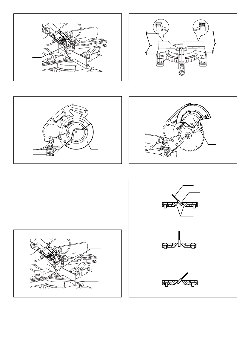
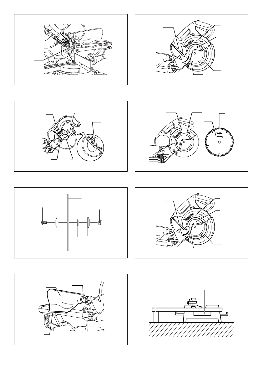
Bench mounting (Fig. 1)
When the tool is shipped, the handle is locked in the
lowered position by the stopper pin. Release the stopper
pin by simultaneously applying a slight downward
pressure on the handle and pulling the stopper pin.
(Fig. 2)
This tool should be bolted with four bolts to a level and
stable surface using the bolt holes provided in the tool’s
base. This will help prevent tipping and possible injury.
FUNCTIONAL DESCRIPTION
WARNING:
• Always be sure that the tool is switched off and
unplugged before adjusting or checking function
on the tool. Failure to switch off and unplug the tool
may result in serious personal injury from accidental
start-up.
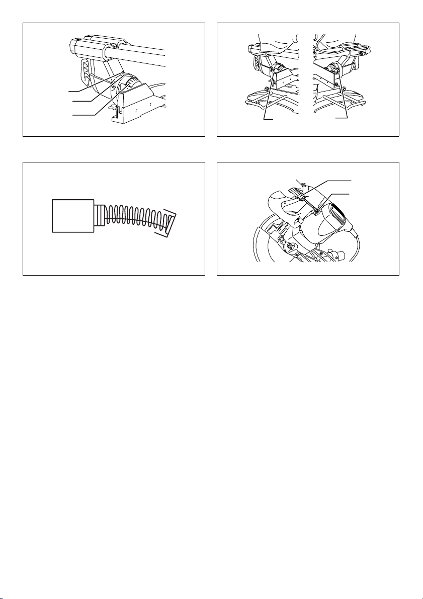
Blade guard (Fig. 3)
When lowering the handle, the blade guard rises
automatically. The blade guard returns to its original
position when the cut is completed and the handle is
raised.
WARNING:
• Never defeat or remove the blade guard or the
spring which attaches to the guard. An exposed
blade as a result of defeated guarding may result in
serious personal injury during operation.
In the interest of your personal safety, always maintain the
blade guard in good condition. Any irregular operation of
the blade guard should be corrected immediately. Check
to assure spring loaded return action of guard.
WARNING:
• Never use the tool if the blade guard or spring are
damaged, faulty or removed. Operation of the tool
with a damaged, faulty or removed guard may result in
serious personal injury.
If the see-through blade guard becomes dirty, or sawdust
adheres to it in such a way that the blade and/or
workpiece is no longer easily visible, unplug the saw and
clean the guard carefully with a damp cloth. Do not use
solvents or any petroleum-based cleaners on the plastic
guard because this may cause damage to the guard.
If the blade guard becomes dirty and needs to be cleaned
for proper operation follow the steps below:
With the tool switched off and unplugged, use the
supplied socket wrench to loosen the hex bolt holding the
center cover. Loosen the hex bolt by turning it
counterclockwise and raise the blade guard and center
cover. (Fig. 4)
With the blade guard so positioned, cleaning can be more
completely and efficiently accomplished. When cleaning
is complete reverse procedure above and secure bolt. Do
not remove spring holding blade guard. If guard becomes
damaged through age or UV light exposure, contact a
Makita service center for a new guard. DO NOT DEFEAT
OR REMOVE GUARD.
Positioning kerf board (Fig. 5 & 6)
This tool is provided with the kerf boards in the turn base
to minimize tearing on the exit side of a cut. The kerf
boards are factory adjusted so that the saw blade does
not contact the kerf boards. Before use, adjust the kerf
boards as follows:
First, unplug the tool. Loosen all the screws (3 each on left
and right) securing the kerf boards. Re-tighten them only
to the extent that the kerf boards can still be easily moved
by hand. Lower the handle fully and push in the stopper
pin to lock the handle in the lowered position. Loosen the
screw which secures the slide poles. Pull the carriage
toward you fully. Adjust the kerf boards so that the kerf
13
Page 14

boards just contact the sides of the blade teeth. Tighten
the front screws (do not tighten firmly). Push the carriage
toward the guide fence fully and adjust the kerf boards so
that the kerf boards just contact the sides of blade teeth.
Tighten the rear screws (do not tighten firmly).
After adjusting the kerf boards, release the stopper pin
and raise the handle. Then tighten all the screws securely.
NOTICE:
• After setting the bevel angle ensure that the kerf
boards are adjusted properly. Correct adjustment of
the kerf boards will help provide proper support of the
workpiece minimizing workpiece tear out.
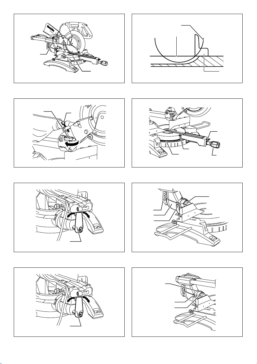
Maintaining maximum cutting capacity
This tool is factory adjusted to provide the maximum
cutting capacity for a 255 mm saw blade.
Unplug the tool before any adjustment is attempted.
When installing a new blade, always check the lower limit
position of the blade and if necessary, adjust it as follows:
(Fig. 7 & 8)
First, unplug the tool. Push the carriage toward the guide
fence fully and lower the handle completely. Use the hex.
wrench to turn the adjusting bolt until the periphery of the
blade extends slightly below the top surface of the turn
base at the point where the front face of the guide fence
meets the top surface of the turn base.
With the tool unplugged, rotate the blade by hand while
holding the handle all the way down to be sure that the
blade does not contact any part of the lower base. Readjust slightly, if necessary.
WARNING:
• After installing a new blade and with the tool
unplugged, always be sure that the blade does not
contact any part of the lower base when the handle
is lowered completely. If a blade makes contact with
the base it may cause kickback and result in serious
personal injury.
Stopper arm (Fig. 9)
The lower limit position of the blade can be easily
adjusted with the stopper arm. To adjust it, move the
stopper arm in the direction of the arrow as shown in the
figure. Adjust the adjusting screw so that the blade stops
at the desired position when lowering the handle fully.
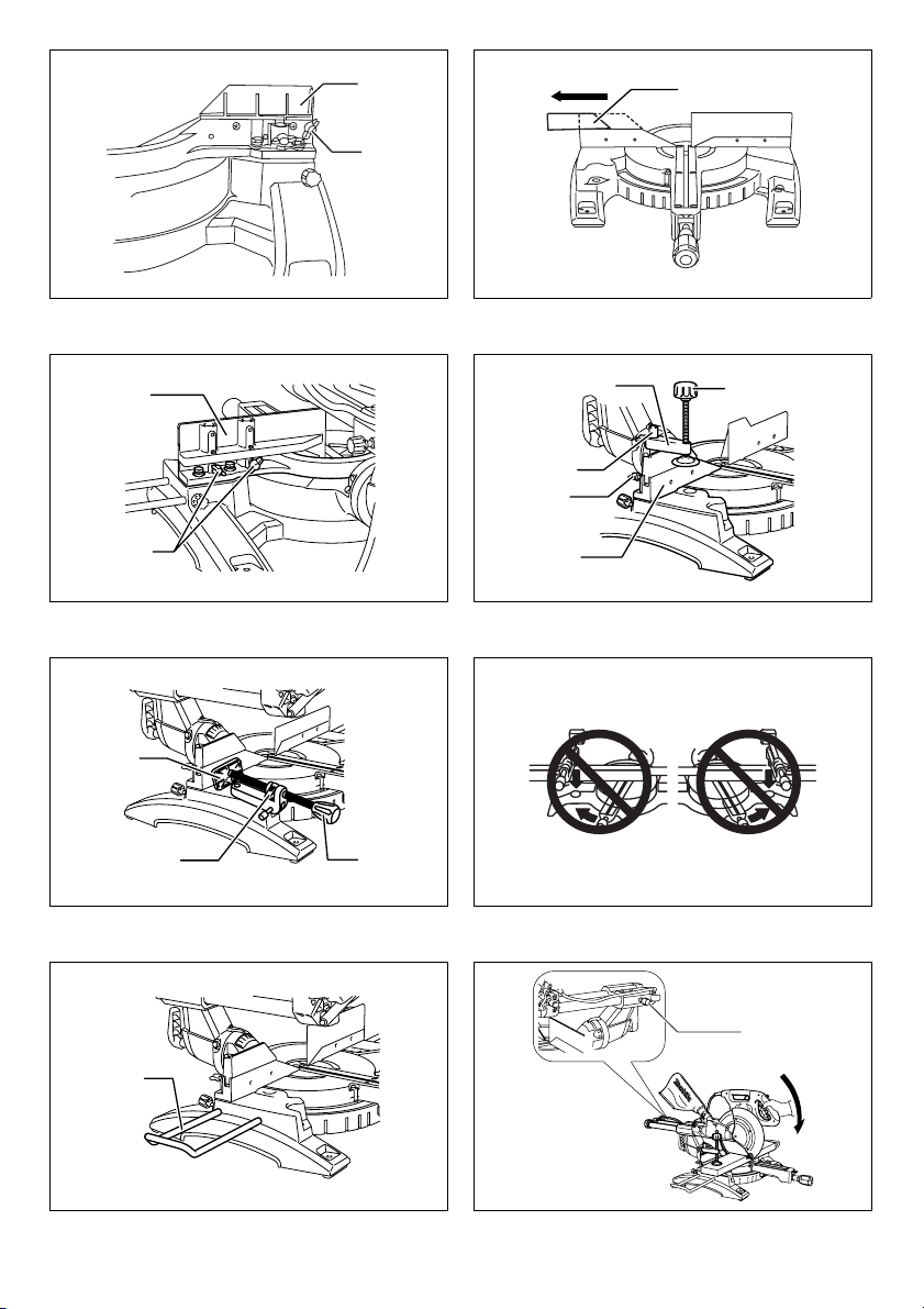
Adjusting the miter angle (Fig. 10)
Loosen the grip by turning counterclockwise. Turn the turn
base while pressing down the lock lever. When you have
moved the grip to the position where the pointer points to
the desired angle on the miter scale, securely tighten the
grip clockwise.
CAUTION:
• After changing the miter angle, always secure the turn
base by tightening the grip firmly.
NOTICE:
• When turning the turn base, be sure to raise the handle
fully.
Adjusting the bevel angle (Fig. 11)
To adjust the bevel angle, loosen the lever at the rear of
the tool counterclockwise. Unlock the arm by pushing the
14
handle somewhat strongly in the direction that you intend
to tilt the saw blade.
NOTE:
• Lever can be adjusted to a different lever angle by
removing the screw holding the lever and securing the
lever at a desired angle. (Fig. 12)
Tilt the saw blade until the pointer points to the desired
angle on the bevel scale. Then tighten the lever clockwise
firmly to secure the arm. (Fig. 13)
When tilting the carriage to the right, tilt the carriage to the
left slightly after loosening the lever and press the
releasing button. With the releasing button being pressed,
tilt the carriage to the right. (Fig. 14)
Tilt the saw blade until the pointer points to the desired
angle on the bevel scale. Then tighten the lever clockwise
firmly to secure the arm.
• When changing bevel angles, be sure to position the
kerf boards appropriately as explained in the
“Positioning kerf boards” section.
CAUTION:
• After changing the bevel angle, always secure the arm
by tightening the lever clockwise.
NOTICE:
• When tilting the saw blade be sure the handle is fully
raised.
• When changing bevel angles, be sure to position the
kerf boards appropriately as explained in the
“Positioning kerf boards” section.
Slide lock adjustment (Fig. 15)
To lock the slide pole, turn the locking screw clockwise.
Switch action
For European countries (Fig. 16)
To prevent the switch trigger from being accidentally
pulled, a lock-off button is provided. To start the tool, push
the lever to the left, press in the lock-off button and then
pull the switch trigger. Release the switch trigger to stop.
WARNING:
• Before plugging in the tool, always check to see
that the switch trigger actuates properly and
returns to the “OFF” position when released. Do
not pull the switch trigger hard without pressing in
the lock-off button. This can cause switch
breakage. Operating a tool with a switch that does not
actuate properly can lead to loss of control and serious
personal injury.
A hole is provided in the switch trigger for insertion of
padlock to lock the tool off.
For all countries other than European countries
(Fig. 17)
To prevent the switch trigger from being accidentally
pulled, a lock-off button is provided. To start the tool,
press in the lock-off button and pull the switch trigger.
Release the switch trigger to stop.
WARNING:
• Before plugging in the tool, always check to see
that the switch trigger actuates properly and
returns to the “OFF” position when released. Do
not pull the switch trigger hard without pressing in
Page 15

the lock-off button. This can cause switch
breakage. Operating a tool with a switch that does not
actuate properly can lead to loss of control and serious
personal injury.
A hole is provided in the switch trigger for insertion of
padlock to lock the tool off.
WARNING:
• Do not use a lock with a shank or cable any smaller
than 6.35 mm in diameter. A smaller shank or cable
may not properly lock the tool in the off position and
unintentional operation may occur resulting in serious
personal injury.
• NEVER use tool without a fully operative switch
trigger. Any tool with an inoperative switch is HIGHLY
DANGEROUS and must be repaired before further
usage or serious personal injury may occur.
• For your safety, this tool is equipped with a lock-off
button which prevents the tool from unintended
starting. NEVER use the tool if it runs when you simply
pull the switch trigger without pressing the lock-off
button. A switch in need of repair may result in
unintentional operation and serious personal injury.
Return tool to a Makita service center for proper repairs
BEFORE further usage.
• NEVER defeat the lock-off button by taping down or
some other means. A switch with a defeated lock-off
button may result in unintentional operation and
serious personal injury.
Electronic function
Soft start feature
• This function allows the smooth start-up of the tool by
limiting the start-up torque.
Laser beam action
For model LS1018L only
NOTE:
• Before the first use, install the dry cells provided
separately from the tool in the cell box. Refer to the
section titled “Replacing the dry cells for laser unit” for
the installment.
CAUTION:
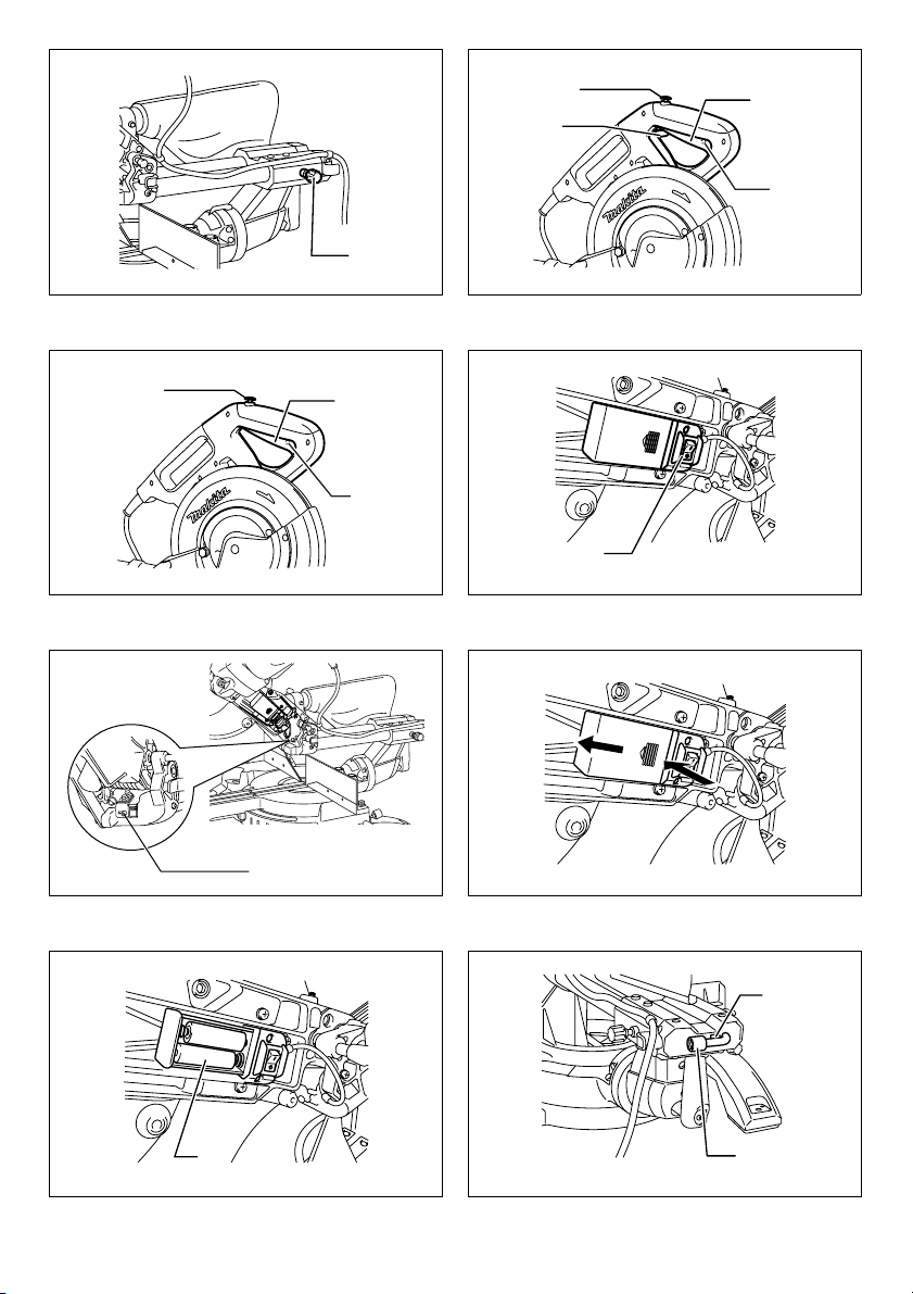
• When not in use, be sure to turn off the laser. (Fig. 18)
CAUTION:
• Never look into the laser beam. Direct laser beam may
injure your eyes.
• LASER RADIATION, DO NOT STARE INTO THE
BEAM, CLASS 2 LASER PRODUCT.
• Before shifting the laser line or performing
maintenance adjustment, be sure to unplug the tool.
To turn on the laser beam, press the upper position (I) of
the switch. To turn off the laser beam, press the lower
position (0) of the switch.
Laser line can be shifted to either the left or right side of
the saw blade by loosening the screw holding the laser
unit box and shifting it in the desired direction. After
shifting, be sure to tighten the screw. (Fig. 19)
Laser line is factory adjusted so that it is positioned within
1 mm from the side surface of the blade (cutting position).
NOTE:
• When laser line appears dim and hard to see because
of direct sunlight, relocate the work area to a place
where there is less direct sunlight.
Replacing the dry cells for laser unit
(Fig. 20 & 21)
Remove the lid for the dry cells for laser unit by sliding
while pressing it. Take out the old dry cells and put the
new ones as shown in the figure. After replacing, return
the lid to cover it.
Cleaning of the lens for the laser light
If the lens for the laser light becomes dirty, or sawdust
adheres to it in such a way that the laser line is no longer
easily visible, unplug the saw and remove and clean the
lens for the laser light carefully with a damp, soft cloth. Do
not use solvents or any petroleum-based cleaners on the
lens.
NOTE:
• When laser line is dim and almost or entirely invisible
because of the direct sunlight in the indoor or outdoor
window-by work, relocate the work area to a place not
exposed to the direct sunlight.
ASSEMBLY
WARNING:
• Always be sure that the tool is switched off and
unplugged before working on the tool. Failure to
switch off and unplug the tool may result in serious
personal injury.
Storage of socket wrench with hex
wrench on its other end (Fig. 22)
The socket wrench is stored as shown in the figure. When
the socket wrench is needed it can be pulled out of the
wrench holder.
After using the socket wrench it can be stored by returning
it to the wrench holder.
Installing or removing saw blade
WARNING:
• Always be sure that the tool is switched off and
unplugged before installing or removing the blade.
Accidental start up of the tool may result in serious
personal injury.
• Use only the Makita socket wrench provided to
install or remove the blade. Failure to use the wrench
may result in overtightening or insufficient tightening of
the hex bolt and serious personal injury. (Fig. 23)
Lock the handle in the raised position by pushing in the
stopper pin. (Fig. 24)
To remove the blade, use the socket wrench to loosen the
hex bolt holding the center cover by turning it
counterclockwise. Raise the blade guard and center
cover. (Fig. 25)
Press the shaft lock to lock the spindle and use the socket
wrench to loosen the hex bolt clockwise. Then remove the
hex bolt, outer flange and blade.
15
Page 16

NOTE:
• If the inner flange is removed be sure to install it on the
spindle with its protrusion facing away from the blade. If
the flange is installed incorrectly the flange will rub
against the machine.
WARNING:
• Before mounting the blade onto the spindle, always
be sure that the correct ring for the blade’s arbor
hole you intend to use is installed between the
inner and the outer flanges. Use of the incorrect
arbor hole ring may result in the improper mounting of
the blade causing blade movement and severe
vibration resulting in possible loss of control during
operation and in serious personal injury. (Fig. 26)
To install the blade, mount it carefully onto the spindle,
making sure that the direction of the arrow on the surface
of the blade matches the direction of the arrow on the
blade case.
Install the outer flange and hex bolt, and then use the
socket wrench to tighten the hex bolt (left-handed)
securely counterclockwise while pressing the shaft lock.
For all countries other than European countries
(Fig. 27)
WARNING:
• The black ring 25 mm in outer diameter and the silver
ring 25.4 mm in outer diameter are factory-installed as
shown in the figure. When using a blade with 25 mm
hole diameter, replace the silver ring with the black
ring. Before mounting the blade onto the spindle,
always be sure that the correct ring for the blade’s
arbor hole you intend to use is installed between
the inner and the outer flanges. Use of the incorrect
arbor hole ring may result in the improper mounting of
the blade causing blade movement and severe
vibration resulting in possible loss of control during
operation and in serious personal injury.
For European countries
CAUTION:
• The ring 30 mm in outer diameter is factory-installed
between the inner and outer flanges.
Install the outer flange and hex bolt, and then use the
socket wrench to tighten the hex bolt securely
counterclockwise while pressing the shaft lock. (Fig. 28)
Return the blade guard and center cover to its original
position. Then tighten the hex bolt clockwise to secure the
center cover. Release the handle from the raised position
by pulling the stopper pin. Lower the handle to make sure
that the blade guard moves properly. Make sure the shaft
lock has released spindle before making cut.
Dust bag (accessory) (Fig. 29)
The use of the dust bag makes cutting operations cleaner
and dust collection easier. To attach the dust bag, fit it
onto the dust nozzle.
When the dust bag is about half full, remove the dust bag
from the tool and pull the fastener out. Empty the dust bag
of its contents, tapping it lightly so as to remove particles
adhering to the insides which might hamper further
collection.
16
NOTE:
If you connect a vacuum cleaner to your saw, cleaner
operations can be performed.
Securing workpiece
WARNING:
• It is extremely important to always secure the
workpiece correctly with the proper type of vise or
crown molding stoppers. Failure to do so may result
in serious personal injury and cause damage to the tool
and/or the workpiece.
• After a cutting operation do not raise the blade
until it has come to a complete stop. The raising of a
coasting blade may result in serious personal injury
and damage to the workpiece.
• When cutting a workpiece that is longer than the
support base of the saw, the material should be
supported the entire length beyond the support
base and at the same height to keep the material
level. Proper workpiece support will help avoid blade
pinch and possible kickback which may result in
serious personal injury. Do not rely solely on the
vertical vise and/or horizontal vise to secure the
workpiece. Thin material tends to sag. Support
workpiece over its entire length to avoid blade pinch
and possible KICKBACK. (Fig. 30)
Guide fence (SLIDING FENCES which are
upper and lower fences) adjustment
(Fig. 31)
WARNING:
• Before operating the tool, make sure that the sliding
fence is secured firmly.
• Before bevel-cutting, make sure that no part of the
tool, especially the blade, contacts the upper and
lower fences when fully lowering and raising the
handle in any position and while moving the
carriage through its full range of travel. If the tool or
blade makes contact with the fence this may result in
kickback or unexpected movement of the material and
serious personal injury. (Fig. 32)
CAUTION:
• When performing bevel cuts, slide the sliding fence to
the left and secure it as shown in the figure. Otherwise,
it will contact the blade or a part of the tool, causing
possible serious injury to the operator.
This tool is equipped with the sliding fence which should
ordinarily be positioned as shown in the figure.
However, when performing left bevel cuts, set it to the left
position as shown in the figure if the tool head contacts it.
When bevel-cutting operations are complete, don’t forget
to return the sliding fence to the original position and
secure it by firmly tightening the clamping screw.
Sub-fence R
WARNING:
• Before operating the tool, make sure that the sub-fence
R is secured firmly.
• Before performing right bevel cuts, remove the subfence R. It will contact the blade or a part of the tool,
Page 17

causing possible serious injury to the operator.
(Fig. 33)
The sub-fence R can be removed from the right side of
the guide fence. To remove the sub-fence R, loosen the
screw which secures the sub-fence R and pull it out.
Follow the removal procedure in reverse to install it.
When bevel-cutting operations are complete, don’t forget
to return the sub-fence R to the original position and
secure it by firmly tightening the clamping screw.
Vertical vise (Fig. 34)
The vertical vise can be installed on either the left or right
side of the guide fence. Insert the vise rod into the hole in
the guide fence and tighten the screw on the back of the
guide fence to secure the vise rod.
Position the vise arm according to the thickness and
shape of the workpiece and secure the vise arm by
tightening the screw. If the screw to secure the vise arm
contacts the guide fence, install the screw on the opposite
side of vise arm. Make sure that no part of the tool
contacts the vise when lowering the handle fully and
pulling or pushing the carriage all the way. If some part
contacts the vise, re-position the vise.
Press the workpiece flat against the guide fence and the
turn base. Position the workpiece at the desired cutting
position and secure it firmly by tightening the vise knob.
WARNING:
• The workpiece must be secured firmly against the
turn base and guide fence with the vise during all
operations. If the workpiece is not properly secured
against the fence the material may move during the
cutting operation causing possible damage to the
blade, causing the material to be thrown and loss of
control resulting in serious personal injury.
Horizontal vise (optional accessory)
(Fig. 35)
The horizontal vise can be installed in two positions on
either the left or right side of the base. When performing
10° or greater miter cuts, install the horizontal vise on the
side opposite the direction in which the turn base is to be
turned. (Fig. 36)
By flipping the vise nut counterclockwise, the vise is
released, and rapidly moves in and out. To grip the
workpiece, push the vise knob forward until the vise plate
contacts the workpiece and flip the vise nut clockwise.
Then turn the vise knob clockwise to secure the
workpiece.
The maximum width of workpiece which can be secured
by the horizontal vise is 215 mm.
When installing the horizontal vise on the right side of the
base, also use the sub-fence R to secure the workpiece
more firmly. Refer to the “Sub-fence R” section described
on previously for installing the sub-fence R.
WARNING:
• Always rotate the vise nut clockwise until the
workpiece is properly secured. If the workpiece is
not properly secured the material may move during the
cutting operation causing possible damage to the
blade, causing the material to be thrown and loss of
control resulting in serious personal injury.
• When cutting a thin workpiece, such as base boards,
against the fence, always use the horizontal vise.
Holders (Fig. 37)
The holders can be installed on either side as a
convenient means of holding workpieces horizontally. Slip
fully the holder rods into the holes in the base. Then
tighten the holders securely with the screws.
WARNING:
• Always support a long workpiece so it is level with
the top surface of the turn base for an accurate cut
and to prevent dangerous loss of tool control.
Proper workpiece support will help avoid blade pinch
and possible kickback which may result in serious
personal injury.
OPERATION
NOTICE:
• Before use, be sure to release the handle from the
lowered position by pulling the stopper pin.
• Do not apply excessive pressure on the handle when
cutting. Too much force may result in overload of the
motor and/or decreased cutting efficiency. Push down
handle with only as much force as is necessary for
smooth cutting and without significant decrease in
blade speed.
• Gently press down the handle to perform the cut. If the
handle is pressed down with force or if lateral force is
applied, the blade will vibrate and leave a mark (saw
mark) in the workpiece and the precision of the cut will
be impaired.
• During a slide cut, gently push the carriage toward the
guide fence without stopping. If the carriage movement
is stopped during the cut, a mark will be left in the
workpiece and the precision of the cut will be impaired.
WARNING:
• Make sure the blade is not contacting the
workpiece, etc. before the switch is turned on.
Turning the tool on with the blade in contact with the
workpiece may result in kickback and serious personal
injury.
1. Press cutting (cutting small workpieces) (Fig. 38)
Workpieces up to 91 mm high and 70 mm wide can be
cut in the following manner.
Push the carriage toward the guide fence fully and
tighten the locking screw clockwise to secure the
carriage. Secure the workpiece correctly with the
proper type of vise. Switch on the tool without the
blade making any contact and wait until the blade
attains full speed before lowering. Then gently lower
the handle to the fully lowered position to cut the
workpiece. When the cut is completed, switch off the
tool and WAIT UNTIL THE BLADE HAS COME TO A
COMPLETE STOP before returning the blade to its
fully elevated position.
WARNING:
• Firmly tighten the knob clockwise so that the
carriage will not move during operation. Insufficient
tightening of the knob may cause possible kickback
which may result in serious personal injury.
17
Page 18

2. Slide (push) cutting (cutting wide workpieces)
(Fig. 39)
Loosen the locking screw counterclockwise so that the
carriage can slide freely. Secure the workpiece with
the proper type of vise. Pull the carriage toward you
fully. Switch on the tool without the blade making any
contact and wait until the blade attains full speed.
Press the handle down and PUSH THE CARRIAGE
TOWARD THE GUIDE FENCE AND THROUGH THE
WORKPIECE. When the cut is completed, switch off
the tool and WAIT UNTIL THE BLADE HAS COME
TO A COMPLETE STOP before returning the blade to
its fully elevated position.
WARNING:
• Whenever performing a slide cut, first pull the
carriage full towards you and press the handle all
the way down, then push the carriage toward the
guide fence. Never start the cut with the carriage
not pulled fully toward you. If you perform the slide
cut without the carriage pulled fully toward you
unexpected kickback may occur and serious personal
injury may result.
• Never attempt to perform a slide cut by pulling the
carriage towards you. Pulling the carriage towards
you while cutting may cause unexpected kickback
resulting in possible serious personal injury.
• Never perform the slide cut with the handle locked in
the lowered position.
• Never loosen the locking screw which secures the
carriage while the blade is rotating. A loose carriage
while cutting may cause unexpected kickback resulting
in possible in serious personal injury.
3. Miter cutting
Refer to the previously covered “Adjusting the miter
angle”.
4. Bevel cut (Fig. 40)
Loosen the lever and tilt the saw blade to set the bevel
angle (Refer to the previously covered “Adjusting the
bevel angle”). Be sure to retighten the lever firmly to
secure the selected bevel angle safely. Secure the
workpiece with a vise. Make sure the carriage is pulled
all the way back toward the operator. Switch on the
tool without the blade making any contact and wait
until the blade attains full speed. Then gently lower the
handle to the fully lowered position while applying
pressure in parallel with the blade and PUSH THE
CARRIAGE TOWARD THE GUIDE FENCE TO CUT
THE WORKPIECE. When the cut is completed, switch
off the tool and WAIT UNTIL THE BLADE HAS COME
TO A COMPLETE STOP before returning the blade to
its fully elevated position.
WARNING:
• After setting the blade for a bevel cut, before
operating the tool ensure that the carriage and
blade will have free travel throughout the entire
range of the intended cut. Interruption of the carriage
or blade travel during the cutting operation may result
in kickback and serious personal injury.
• While making a bevel cut keep hands out of the
path of the blade. The angle of the blade may confuse
the operator as to the actual blade path while cutting
and contact with the blade will result in serious
personal injury.
• The blade should not be raised until it has come to
a complete stop. During a bevel cut the piece cut off
may come to rest against the blade. If the blade is
raised while it is rotating the cut-off piece maybe
ejected by the blade causing the material to fragment
which may result in serious personal injury.
NOTICE:
• When pressing down the handle, apply pressure in
parallel with the blade. If a force is applied
perpendicularly to the turn base or if the pressure
direction is changed during a cut, the precision of the
cut will be impaired.
• Before bevel-cutting, an adjustment of the upper fence
and lower fence maybe required. Refer to the section
titled “Guide fence adjustment”.
CAUTION:
• Always remove the sub-fence R so that it does not
interfere any part of the carriage when performing right
bevel cuts.
5. Compound cutting
Compound cutting is the process in which a bevel
angle is made at the same time in which a miter angle
is being cut on a workpiece. Compound cutting can be
performed at the angle shown in the table.
Miter angle Bevel angle
Left and Right 0° - 45° Left and Right 0° - 45°
When performing compound cutting, refer to “Press
cutting”, “Slide cutting”, “Miter cutting” and “Bevel cut”
explanations.
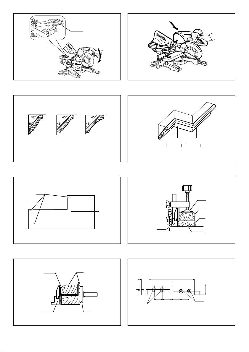
6. Cutting crown and cove moldings
Crown and cove moldings can be cut on a compound
miter saw with the moldings laid flat on the turn base.
There are two common types of crown moldings and
one type of cove moldings; 52/38° wall angle crown
molding, 45° wall angle crown molding and 45° wall
angle cove molding. See illustrations. (Fig. 41)
There are crown and cove molding joints which are
made to fit “Inside” 90° corners ((1) and (2) in Fig. A)
and “Outside” 90° corners ((3) and (4) in Fig. A).
(Fig. 42 & 43)
Measuring
Measure the wall length and adjust workpiece on table
to cut wall contact edge to desired length. Always
make sure that cut workpiece length at the back of
the workpiece is the same as wall length. Adjust cut
length for angle of cut. Always use several pieces for
test cuts to check the saw angles.
When cutting crown and cove moldings, set the bevel
angle and miter angle as indicated in the table (A) and
position the moldings on the top surface of the saw
base as indicated in the table (B).
18
Page 19

In the case of left bevel cut
Table (A)
For inside
corner
For outside
corner
Molding
position in
Fig. A
(1)
(2)
(3)
(4) Right 31.6° Right 35.3°
Bevel angle Miter angle
52/38° type 45° type 52/38° type 45° type
Right 31.6° Right 35.3°
Left 33.9° Left 30°
Left 31.6° Left 35.3°
Table (B)
Molding
Molding edge against
For inside
corner
For outside
corner
position in
Fig. A
(1)
(2)
(3)
(4)
guide fence
Ceiling contact edge
should be against guide
fence.
Wall contact edge should
be against guide fence.
Ceiling contact edge
should be against guide
fence.
Finished piece
Finished piece will be on
the Left side of blade.
Finished piece will be on
the Right side of blade.
Example:
In the case of cutting 52/38° type crown molding for
position (1) in Fig. A:
• Tilt and secure bevel angle setting to 33.9° LEFT.
• Adjust and secure miter angle setting to 31.6°
RIGHT.
• Lay crown molding with its broad back (hidden)
surface down on the turn base with its CEILING
CONTACT EDGE against the guide fence on the
saw.
• The finished piece to be used will always be on the
LEFT side of the blade after the cut has been
made.
In the case of right bevel cut
Table (A)
For inside
corner
For outside
corner
Molding
position in
Fig. A
(1)
(2)
(3)
(4) Right 31.6° Right 35.3°
Bevel angle Miter angle
52/38° type 45° type 52/38° type 45° type
Right 31.6° Right 35.3°
Right 33.9° Right 30°
Left 31.6° Left 35.3°
Table (B)
Molding
Molding edge against
For inside
corner
For outside
corner
position in
guide fence
Fig. A
Wall contact edge should
(1)
be against guide fence.
(2) Ceiling contact edge
should be against guide
(3)
fence.
Wall contact edge should
(4)
be against guide fence.
Finished piece
Finished piece will be on
the Right side of blade.
Finished piece will be on
the Left side of blade.
Example:
In the case of cutting 52/38° type crown molding for
position (1) in Fig. A:
• Tilt and secure bevel angle setting to 33.9° RIGHT.
• Adjust and secure miter angle setting to 31.6°
RIGHT.
• Lay crown molding with its broad back (hidden)
surface down on the turn base with its WALL
CONTACT EDGE against the guide fence on the
saw.
• The finished piece to be used will always be on the
RIGHT side of the blade after the cut has been
made.
7. Cutting aluminum extrusion (Fig. 44 & 45)
When securing aluminum extrusions, use spacer
blocks or pieces of scrap as shown in the figure to
prevent deformation of the aluminum. Use a cutting
lubricant when cutting the aluminum extrusion to
prevent build-up of the aluminum material on the
blade.
WARNING:
• Never attempt to cut thick or round aluminum
extrusions. Thick or round aluminum extrusions can
be difficult to secure and may work loose during the
cutting operation which may result in loss of control and
serious personal injury.
8. Wood facing
Use of wood facing helps to assure splinter-free cuts
in workpieces. Attach a wood facing to the guide fence
using the holes in the guide fence.
See the figure concerning the dimensions for a
suggested wood facing. (Fig. 46)
CAUTION:
• Use straight wood of even thickness as the wood
facing.
WARNING:
• Use screws to attach the wood facing to the guide
fence. The screws should be installed so that the
screw heads are below the surface of the wood
facing so that they will not interfere with the
positioning of the material being cut. Misalignment
of the material being cut can case unexpected
movement during the cutting operation which may
result in a loss of control and serious personal injury.
NOTICE:
• When the wood facing is attached, do not turn the turn
base with the handle lowered. The blade and/or the
wood facing will be damaged.
9. Groove cutting (Fig. 47)
A dado type cut can be made by proceeding as
follows:
Adjust the lower limit position of the blade using the
adjusting screw and the stopper arm to limit the cutting
depth of the blade. Refer to “Stopper arm” section
described previously.
After adjusting the lower limit position of the blade, cut
parallel grooves across the width of the workpiece
using a slide (push) cut as shown in the figure. Then
remove the workpiece material between the grooves
with a chisel.
WARNING:
• Do not attempt to perform this type of cut by using
a wider type blade or dado blade. Attempting to
make a groove cut with a wider blade or dado blade
could lead to unexpected cutting results and kickback
which may result in serious personal injury.
19
Page 20

• Be sure to return the stopper arm to the original
position when performing other than groove
cutting. Attempting to make cuts with the stopper arm
in the incorrect position could lead to unexpected
cutting results and kickback which may result in serious
personal injury.
CAUTION:
• Be sure to return the stopper arm to the original
position when performing other than groove cutting.
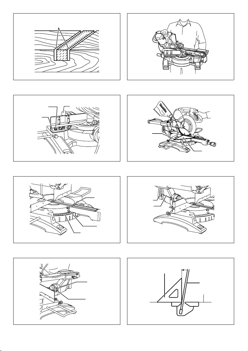
Carrying tool (Fig. 48)
Make sure that the tool is unplugged. Secure the blade at
0° bevel angle and the turn base at the full right miter
angle position. Secure the slide poles so that the lower
slide pole is locked in the position of the carriage fully
pulled to operator and the upper poles are locked in the
position of the carriage fully pushed forward to the guide
fence (refer to the section titled “Slide lock adjustment”.)
Lower the handle fully and lock it in the lowered position
by pushing in the stopper pin.
Wind the power supply cord using the cord rests.
WARNING:
• Stopper pin is only for carrying and storage
purposes and should never be used for any cutting
operations. The use of the stopper pin for cutting
operations may cause unexpected movement of the
saw blade resulting in kickback and serious personal
injury.
Carry the tool by holding both sides of the tool base as
shown in the figure. If you remove the holders, dust bag,
etc., you can carry the tool more easily.
CAUTION:
• Always secure all moving portions before carrying the
tool. If portions of the tool move or slide while being
carried loss of control or balance may occur resulting in
personal injury.
MAINTENANCE
WARNING:
• Always be sure that the tool is switched off and
unplugged before attempting to perform inspection
or maintenance. Failure to unplug and switch off the
tool may result in accidental start up of the tool which
may result in serious personal injury.
• Always be sure that the blade is sharp and clean
for the best and safest performance. Attempting a
cut with a dull and /or dirty blade may cause kickback
and result in a serious personal injury.
NOTICE:
• Never use gasoline, benzine, thinner, alcohol or the
like. Discoloration, deformation or cracks may result.
Adjusting the cutting angle
This tool is carefully adjusted and aligned at the factory,
but rough handling may have affected the alignment. If
your tool is not aligned properly, perform the following:
1. Miter angle (Fig. 49)
Push the carriage toward the guide fence and tighten
the locking screw to secure the carriage.
20
Loosen the grip which secures the turn base. Turn the
turn base so that the pointer points to 0° on the miter
scale. Then turn the turn base slightly clockwise and
counterclockwise to seat the turn base in the 0° miter
notch. (Leave as it is if the pointer does not point to
0°.) Loosen the hex sockets bolts securing the guide
fence using the socket wrench. (Fig. 50)
Lower the handle fully and lock it in the lowered
position by pushing in the stopper pin. Square the side
of the blade with the face of the guide fence using a
triangular rule, try-square, etc. Then securely tighten
the hex socket bolts on the guide fence in order
starting from the right side. (Fig. 51)
Make sure that the pointer points to 0° on the miter
scale. If the pointer does not point to 0°, loosen the
screw which secures the pointer and adjust the pointer
so that it will point to 0°.
2. Bevel angle
(1) 0° bevel angle (Fig. 52)
Push the carriage toward the guide fence and
tighten the locking screw to secure the carriage.
Lower the handle fully and lock it in the lowered
position by pushing in the stopper pin. Loosen the
lever at the rear of the tool. (Fig. 53)
Turn the hex bolt on the right side of the arm two
or three revolutions counterclockwise to tilt the
blade to the right. (Fig. 54)
Carefully square the side of the blade with the top
surface of the turn base using the triangular rule,
try-square, etc. by turning the hex bolt on the right
side of the arm clockwise. Then tighten the lever
securely. (Fig. 55)
Make sure that the pointer on the arm point to 0°
on the bevel scale on the arm holder. If they do not
point to 0°, loosen the screw which secure the
pointer and adjust it so that it will point to 0°.
(2) 45° bevel angle (Fig. 56)
Adjust the 45° bevel angle only after performing 0°
bevel angle adjustment. To adjust left 45° bevel
angle, loosen the lever and tilt the blade to the left
fully. Make sure that the pointer on the arm points
to 45° on the bevel scale on the arm holder. If the
pointer does not point to 45°, turn the 45° bevel
angle adjusting bolt on the right side of the arm
holder until the pointer points to 45°.
To adjust the right 45° bevel angle, perform the
same procedure as that described above.
(Fig. 57)
Remove and check the carbon brushes regularly. Replace
when they wear down to 3 mm in length. Keep the carbon
brushes clean and free to slip in the holders. Both carbon
brushes should be replaced at the same time. Use only
identical carbon brushes. (Fig. 58)
Use a screwdriver to remove the brush holder caps. Take
out the worn carbon brushes, insert the new ones and
secure the brush holder caps.
After use
• After use, wipe off chips and dust adhering to the tool
with a cloth or the like. Keep the blade guard clean
according to the directions in the previously covered
section titled “Blade guard”. Lubricate the sliding
portions with machine oil to prevent rust.
Page 21

• When storing the tool, pull the carriage toward you
fully.
To maintain product SAFETY and RELIABILITY, repairs,
any other maintenance or adjustment should be
performed by Makita Authorized Service Centers, always
using Makita replacement parts.
ACCESSORIES
WARNING:
• These Makita accessories or attachments are
recommended for use with your Makita tool
specified in this manual. The use of any other
accessories or attachments may result in serious
personal injury.
• Only use the Makita accessory or attachment for its
stated purpose. Misuse of an accessory or
attachment may result in serious personal injury.
If you need any assistance for more details regarding
these accessories, ask your local Makita Service
Center.
• Steel & Carbide-tipped saw blades
Miter saw blades
Combination
Crosscutting
Fine cross cuts
Non-ferrous
metals miter saw
blades
• Sub-fence R
• Vise assembly (Horizontal vise)
• Vertical vise
• Socket wrench with hex wrench on its other end
• Holder
• Dust bag
• Elbow
• Triangular rule
For smooth and precise cutting in
various materials.
General purpose blade for fast and
smooth rip, crosscuts and miters.
For smoother cross grain cuts. Slices
cleanly against the grain.
For sand-free cuts cleanly against the
grain.
For miters in aluminum, copper,
brass, tubing, and other non-ferrous
metals.
WARNING:
• The vibration emission during actual use of the power
tool can differ from the declared emission value
depending on the ways in which the tool is used.
• Be sure to identify safety measures to protect the
operator that are based on an estimation of exposure in
the actual conditions of use (taking account of all parts
of the operating cycle such as the times when the tool
is switched off and when it is running idle in addition to
the trigger time).
For European countries only
ENG015-2
Noise and Vibration
The typical A-weighted noise levels are
sound pressure level: 97 dB (A)
sound power level: 103 dB (A)
Uncertainty: 3 dB (A)
Wear ear protection.
The typical weighted root mean square acceleration value
is not more than 2.5 m/s
Uncertainty (K): 1.5 m/s
2
.
2
These values have been obtained according to EN61029.
For European countries only
ENH003-12
EC Declaration of Conformity
We Makita Corporation as the responsible
manufacturer declare that the following Makita
machine(s):
Designation of Machine:
Slide Compound Miter Saw
Model No./ Type: LS1018, LS1018L
are of series production and
Conforms to the following European Directives:
2006/42/EC
And are manufactured in accordance with the following
standards or standardised documents:
EN61029
The technical documentation is kept by our authorised
representative in Europe who is:
Makita International Europe Ltd.,
Michigan Drive, Tongwell,
Milton Keynes, MK15 8JD, England
6. 11. 2009
Noise
ENG905-1
The typical A-weighted noise level determined according
to EN61029:
Sound pressure level (L
Sound power level (L
Uncertainty (K): 3 dB (A)
): 97 dB (A)
pA
): 103 dB (A)
WA
Wear ear protection.
Vibration
ENG900-1
The vibration total value (tri-axial vector sum) determined
according to EN61029:
Vibration emission (a
Uncertainty (K): 1.5 m/s
): 2.5 m/s2 or less
h
2
ENG901-1
• The declared vibration emission value has been
measured in accordance with the standard test method
and may be used for comparing one tool with another.
• The declared vibration emission value may also be
used in a preliminary assessment of exposure.
Tomoyasu Kato
Director
Makita Corporation
3-11-8, Sumiyoshi-cho,
Anjo, Aichi, JAPAN
21
Page 22

NEDERLANDS (Originele instructies)
Verklaring van het onderdelenoverzicht
1. Vergrendelpen
2. Bouten
3. Beschermkap
4. Zaagsnedeplank
5. Schroef
6. Zaagblad
7. Zaagtand
8. Links verticaal-verstekzagen
9. Rechtzagen
10. Rechts verticaal-verstekzagen
11. Stelbout
12. Draaitafel
13. Bovenoppervlak van draaitafel
14. Rand van zaagblad
15. Geleider
16. Aanslagarm
17. Stelschroef
18. Horizontaal-
verstekschaalverdeling
19. Aanwijspunt
20. Vergrendelknop
21. Handvat
22. Hendel
23. Arm
24. Verticaal-verstekschaalverdeling
25. Ontgrendelknop
26. Borgschroef
27. Uit-vergrendelknop
28. Aan/uit-schakelaar
29. Gat voor hangslot
30. Schakelaar van de laserstraal
31. Bevestigingsschroef van de
lasereenheid
32. Batterij
33. Dopsleutel met aan het andere
uiteinde een inbussleutel
34. Gereedschaphouder
35. Dopsleutel
36. Zaagbladhuis
37. Middenafdekking
38. Zeskantbout
39. Pijl
40. Asvergrendeling
41. Zeskantbout (met linkse
schroefdraad)
42. Buitenflens
43. Ring
44. Binnenflens
45. As
46. Stofafzuigaansluitmond
47. Stofzak
48. Sluiting
49. Steun
50. Verschuifbare geleider
51. Klembout
52. Hulpgeleider rechts
53. Schroeven
54. Arm van bankschroef
55. Draaiknop van bankschroef
56. Stang van bankschroef
57. Drukplaat van bankschroef
58. Moer van bankschroef
59. Werkstuksteun
60. Kroon-profiellijst met een
wandhoek van van 52/38°
61. Kroon-profiellijst met een
wandhoek van 45°
62. Kwarthol-profiellijst met een
wandhoek van 45°
63. Binnenhoek
64. Buitenhoek
65. Bankschroef
66. Vulblok
67. Aluminiumprofiel
68. Horizontale bankschroef (los
verkrijgbaar)
69. Gaten
70. Groeven zagen met zaagblad
71. Geodriehoek
72. Stelbout 0°
73. Stelbout voor verticaalverstekhoek van 45° naar links
74. Stelbout voor verticaalverstekhoek van 45° naar rechts
75. Schroevendraaier
76. Koolborsteldop
TECHNISCHE GEGEVENS
Model LS1018/LS1018L
Diameter blad 255 mm - 260 mm
Diameter middengat
Voor alle niet-Europese landen 25,4 mm
Voor Europese landen 30 mm
Max. zaagdikte (h x b) met diameter van 260 mm
Horizontaal-verstekhoek
0° 50 mm x 310 mm 91 mm x 310 mm 31 mm x 310 mm
45° 50 mm x 220 mm 91 mm x 220 mm 31 mm x 220 mm
60° (rechts) - 91 mm x 153 mm -
Nullasttoerental (min
Type Laser (alleen LS1018L) Rode laserstraal 650 nm, <1 mW (laser van klasse 2)
AFmetingen (l x b x h) 825 mm x 536 mm x 633 mm
Netto gewicht Voor alle niet-Europese landen............ 19,8 kg
Veiligheidsklasse /II
• Als gevolg van ons doorlopende onderzoeks- en ontwikkelingsprogramma, zijn de technische gegevens van dit
gereedschap onderhevig aan veranderingen zonder voorafgaande kennisgeving.
• De technische gegevens kunnen van land tot land verschillen.
• Gewicht volgens EPTA-procedure 01/2003
62
-1
) 4.300
45° (links) 0° 45° (rechts)
Verticaal-verstekhoek
Voor Europese landen............ 19,9 kg
Page 23

Symbolen END222-1
Hieronder staan de symbolen die voor dit gereedschap
worden gebruikt. Zorg ervoor dat u weet wat ze
betekenen alvorens het gereedschap te gebruiken.
Bewaar alle waarschuwingen en
instructies om in de toekomst te
kunnen raadplegen.
............. Lees de gebruiksaanwijzing.
............. DUBBEL GEÏSOLEERD
......... Om letsel door rondvliegende
houtsnippers te voorkomen, blijft u na het
zagen de zaagkop omlaag geduwd
houden totdat het zaagblad volledig tot
stilstand is gekomen.
Voor het uitvoeren van schuivend zagen
trekt u eerst de slede helemaal naar u
toe, brengt u vervolgens de handgreep
omlaag, en duwt u tenslotte de slede
naar de geleider.
............. Houd handen en vingers uit de buurt van
de zaagband.
.......... Stel de verschuifbare geleiders zo af dat
ze niet geraakt worden door het zaagblad
en de beschermkap.
.......... Verwijder altijd SUBGELEIDER R bij
verticaal-verstekzagen rechts. Zoniet kan
de operator ernstig gewond raken.
...... Kijk nooit rechtstreeks in de laserstraal.
De rechtstreekse laserstraal kan uw
ogen beschadigen.
Gebruiksdoeleinden
Het gereedschap is bedoeld voor nauwkeurig recht- en
verstekzagen in hout. Als het juiste zaagblad wordt
gebruikt, kan dit gereedschap ook aluminium zagen.
Voe din g
Het gereedschap mag uitsluitend worden aangesloten op
een voeding met dezelfde spanning als aangegeven op
het typeplaatje en werkt alleen op enkele-fase
wisselstroom. Het gereedschap is dubbel geïsoleerd
volgens de Europese norm en mag derhalve ook op een
niet-geaard stopcontact worden aangesloten.
ENE006-1
ENF002-1
Algemene
veiligheidswaarschuwingen voor
elektrisch gereedschap
WAARSCHUWING Lees alle
veiligheidswaarschuwingen en alle instructies. Het
niet volgen van de waarschuwingen en instructies kan
leiden tot elektrische schokken, brand en/of ernstig letsel.
GEA010-1
AANVULLENDE
VEILIGHEIDSVOORSCHRIFTEN
VOOR GEREEDSCHAP
1. Draag oogbescherming.
2. Houd uw handen uit de buurt van het pad van het
zaagblad. Voorkom contact met het nog
nadraaiende zaagblad. Het kan nog steeds ernstig
letsel veroorzaken.
3. Bedien de cirkelzaag niet zonder dat de
beschermkappen zijn aangebracht. Controleer
voor ieder gebruik of de beschermkap van het
zaagblad goed sluit. Gebruik de cirkelzaag niet als
de beschermkap van het zaagblad niet vrij kan
bewegen en onmiddellijk sluit. Zet de
beschermkap van het zaagblad nooit vast in de
geopende stand.
4. Zaag nooit uit de vrije hand. Het werkstuk moet voor
ieder gebruik met behulp van de bankschroef stevig
worden vastgeklemd op de draaitafel en tegen de
geleider. Houd het werkstuk nooit met uw handen
vast.
5. Reik nooit rondom het zaagblad.
6. Schakel het gereedschap uit en wacht tot het
zaagblad stilstaat voordat u het werkstuk
verplaatst of de instelling van het gereedschap
verandert.
7. Trek de stekker van het gereedschap uit het
stopcontact voordat u het zaagblad vervangt of
onderhoud pleegt.
8. Zet altijd alle beweegbare delen vast voordat u het
gereedschap draagt.
9. De vergrendelpen, waarmee de zaagkop in de
onderste stand wordt vergrendeld, is uitsluitend
bedoeld te worden gebruikt tijdens het dragen en
bewaren van het gereedschap, en niet tijdens het
zagen.
10. Gebruik het gereedschap niet in de buurt van
ontvlambare vloeistoffen of gassen. De elektrische
werking van het gereedschap kan een explosie en
brand veroorzaken bij blootstelling aan ontvlambare
vloeistoffen of gassen.
11. Controleer vóór het gebruik het zaagblad
zorgvuldig op barsten of beschadiging.
Vervang een gebarsten of beschadigde zaagblad
meteen.
12. Gebruik uitsluitend flenzen die geschikt zijn voor
dit gereedschap.
13. Wees voorzichtig dat u niet de as, flenzen (met
name het montagevlak) of bout beschadigt. Als
deze onderdelen beschadigd raken, kan het
zaagblad breken.
14. Zorg ervoor dat de draaitafel stevig vast staat
zodat deze tijdens het zagen niet beweegt.
15. Verwijder voor uw eigen veiligheid alle spaanders,
kleine stukjes hout, enz., vanaf het tafeloppervlak
voordat u het gereedschap bedient.
ENB034-6
63
Page 24

16. Voorkom dat u in spijkers zaagt. Inspecteer het
werkstuk op spijkers en verwijder deze zo nodig
voordat u ermee begint te werken.
17. Zorg ervoor dat de asvergrendeling is ontgrendeld
voordat u het gereedschap inschakelt.
18. Controleer dat het zaagblad in zijn laagste stand
de draaitafel niet raakt.
19. Houd de handgreep stevig vast. Let erop dat het
zaagblad iets op en neer beweegt tijdens het
starten en stoppen.
20. Zorg ervoor dat het zaagblad het werkstuk niet
raakt voordat u het gereedschap hebt
ingeschakeld.
21. Laat het gereedschap een tijdje draaien voordat u
het op het werkstuk gebruikt. Controleer op
trillingen of schommelingen die op onjuiste
bevestiging of een slecht uitgebalanceerd
zaagblad kunnen wijzen.
22. Wacht totdat het zaagblad op volle snelheid draait
voordat u begint te zagen.
23. Stop onmiddellijk met het gebruik als u iets
abnormaals opmerkt.
24. Probeer niet de aan/uit-schakelaar in de aan-stand
vast te zetten.
25. Blijf te allen tijde geconcentreerd, met name
tijdens zich herhalende, monotone bedieningen.
Laat u niet leiden door een vals gevoel van
veiligheid. Het zaagblad kent geen medelijden!
26. Gebruik altijd de accessoires die in deze
gebruiksaanwijzing aanbevolen worden. Gebruik
van ongeschikte accessoires, zoals slijpschijven,
kan tot letsel leiden.
27. Gebruik de cirkelzaag niet voor het zagen van
andere materialen dan hout, aluminium en
dergelijke.
28. Sluit de verstekzaag aan op een stofafzuig- en
stofopvanginrichting tijdens het zagen.
29. Kies het juiste zaagblad voor het materiaal dat u
wilt zagen.
30. Wees voorzichtig bij het zagen van gleuven.
31. Vervang de zaagsnedeplank als deze versleten is.
32. Zaagbladen van hooggelegeerd snelstaal (HSS)
mogen niet worden gebruikt.
33. Stof dat tijdens de werkzaamheden vrijkomt, kan
chemische stoffen bevatten die kanker,
geboortedefecten of andere voortplantingsschade
kunnen veroorzaken. Enkele voorbeelden van
deze chemische stoffen zijn:
• lood van loodhoudende verfstoffen en
• arsenicum en chroom van chemisch behandeld
hout.
Uw risico van deze blootstellingen varieert en
hangt af van hoe vaak u dit soort bewerkingen
uitvoert. Om blootstelling aan deze chemische
bestanddelen te verminderen: moeten de
werkzaamheden uitgevoerd worden in een goed
geventileerde werkomgeving en
gebruikmakend van goedgekeurd
beschermende hulpmiddelen, zoals
stofmaskers die ontworpen zijn om
microscopisch kleine deeltjes te filteren.
34. Om het geluidsniveau te verlagen, zorgt u er altijd
voor dat het zaagblad scherp en schoon is.
64
35. De gebruiker moet voldoende getraind zijn in het
gebruik, afstelling en bediening van het
gereedschap.
36. Gebruik een zaagblad dat op de juiste wijze
geslepen is. Houd u aan het maximumtoerental
aangegeven op het zaagblad.
37. U mag niet het afgezaagde stuk of andere delen
van het werkstuk uit het zaaggebied verwijderen
terwijl het zaagblad nog draait en de zaagkop nog
niet in de ruststand staat.
38. Gebruik alleen zaagbladen die aanbevolen worden
door de fabrikant en die voldoen aan de norm
EN847-1.
39. Draag handschoenen bij het hanteren van de
zaagbladen (zaagbladen moeten zo mogelijk in
een verpakking worden gedragen) en ruw
materiaal.
40. Indien voorzien van een laser, mag de laser niet
worden vervangen door een ander type laser.
Reparaties dienen correct te worden uitgevoerd.
BEWAAR DEZE INSTRUCTIES.
VOORBEREIDINGEN
Tafelopstelling (zie afb. 1)
Wanneer u het gereedschap koopt is de handgreep
vergrendeld in de onderste stand door middel van de
vergrendelpen. Maak de vergrendelpen los door eraan te
trekken terwijl u ondertussen de handgreep lichtjes
omlaag drukt. (zie afb. 2)
Dit gereedschap moet met vier bouten worden bevestigd
op een horizontale en stabiele ondergrond met
gebruikmaking van de boutgaten in de voeten van het
gereedschap. Hierdoor wordt voorkomen dat het
gereedschap kan omvallen en letsel kan veroorzaken.
BESCHRIJVING VAN DE
FUNCTIES
WAARSCHUWING:
• Controleer altijd of het gereedschap is
uitgeschakeld en de stekker uit het stopcontact is
getrokken alvorens de functies van het
gereedschap te controleren of af te stellen. Indien
het gereedschap niet wordt uitgeschakeld en de
stekker niet wordt uitgetrokken, kan het ongewild in
werking treden met mogelijk ernstige verwondingen tot
gevolg.
Beschermkap (zie afb. 3)
Wanneer u de handgreep omlaag duwt, gaat de
beschermkap automatisch omhoog. Nadat de zaagsnede
is voltooid en de handgreep omhoog gaat, keert de
beschermkap automatisch terug naar zijn oorspronkelijke
stand.
WAARSCHUWING:
• De beschermkap en de veer die eraan vastzit
mogen nooit worden uitgeschakeld noch
verwijderd. Een blootliggend zaagblad wegens
ontbrekende bescherming kan resulteren in ernstige
verwondingen.
Page 25

Omwille van uw persoonlijke veiligheid zorgt u ervoor dat
de beschermkap altijd goed werkt. Iedere
onregelmatigheid in de werking van de beschermkap
moet onmiddellijk worden gecorrigeerd. Controleer de
werking van de trekveer van de beschermkap.
WAARSCHUWING:
• Gebruik het gereedschap nooit met een
beschadigde, defecte of verwijderde beschermkap
of veer. Gebruik van het gereedschap met een
beschadigde, defecte of verwijderde beschermkap kan
resulteren in ernstige verwondingen.
Als de doorzichtige beschermkap vuil is geworden of er
zaagsel aan kleeft zodat het zaagblad en/of het werkstuk
niet meer goed zichtbaar is, trekt u de stekker uit het
stopcontact en maakt u de beschermkap voorzichtig
schoon met een vochtige doek. Gebruik geen solventen
noch reinigingsmiddelen op basis van petroleum voor de
plastic beschermkap omdat deze hierdoor kan worden
beschadigd.
Wanneer de beschermkap vuil is en moet worden
gereinigd, gaat u als volgt tewerk:
Schakel het gereedschap uit, trek de stekker uit het
stopcontact en draai met behulp van de meegeleverde
dopsleutel de zeskantbout los waarmee de
middenafdekking is bevestigd. Draai de zeskantbout los
door deze linksom te draaien en til de beschermkap en
middenafdekking op. (zie afb. 4)
Met de beschermkap in deze stand kan deze effectiever
en vollediger worden schoongemaakt. Nadat u klaar bent
met het schoonmaken, volgt u de bovenstaande
procedure in omgekeerde volgorde en draait u de bout
weer vast. Verwijder niet de veer waarmee de
beschermkap is vastgezet. Als de beschermkap is
beschadigd door ouderdom of blootstelling aan
ultravioletlicht, neemt u contact op met een Makitaservicecentrum om een nieuwe beschermkap te
bestellen. DE BESCHERMKAP NIET UITSCHAKELEN
NOCH VERWIJDEREN.
De zaagsnedeplanken afstellen (zie afb. 5
en 6)
Dit gereedschap is voorzien van zaagsnedeplanken in de
draaitafel om splinteren aan de uitgangszijde van de
zaagsnede te minimaliseren. De zaagsnedeplanken zijn
in de fabriek zodanig afgesteld dat het zaagblad de
zaagsnedeplanken niet raakt. Stel vóór gebruik de
zaagsnedeplanken als volgt af:
Trek eerst de stekker van het gereedschap uit het
stopcontact. Draai alle schroeven los waarmee de
zaagsnedeplanken zijn bevestigd (3 links en 3 rechts).
Draai ze daarna licht aan zodanig dat de
zaagsnedeplanken nog gemakkelijk met de hand kunnen
worden bewogen. Breng de handgreep helemaal omlaag
en duw de vergrendelpen in om de handgreep in de
onderste stand te vergrendelen. Draai de borgschroef los
waarmee de glijstangen zijn vergrendeld. Trek de slede
helemaal naar u toe. Stel de zaagsnedeplanken zodanig
af dat de zaagsnedeplanken net de zijkant van de
zaagtanden raken. Draai de voorste schroeven vast (draai
ze niet strak vast). Duw de slede helemaal naar de
geleider en stel de zaagsnedeplanken zodanig af dat de
zaagsnedeplanken net de zijkant van de zaagtanden
raken. Draai de achterste schroeven vast (draai ze niet
strak vast).
Na het afstellen van de zaagsnedeplanken, ontgrendelt u
de vergrendelpen en brengt u de handgreep omhoog.
Draai daarna alle schroeven stevig vast.
KENNISGEVING:
• Controleer na het instellen van de verticaalverstekhoek of de zaagsnedeplanken goed zijn
afgesteld. Correct afgestelde zaagsnedeplanken
ondersteunen het werkstuk optimaal met een minimum
aan beweging.
Maximale zaagdikte behouden
Dit gereedschap is in de fabriek afgesteld om de
maximale zaagdikte te leveren met een zaagblad met een
diameter van 255 mm.
Trek de stekker van het gereedschap uit het stopcontact
voordat u afstellingen maakt. Controleer bij het
aanbrengen van een nieuw zaagblad altijd de onderste
stand van het zaagblad en stel deze zo nodig als volgt af:
(zie afb. 7 en 8)
Trek eerst de stekker van het gereedschap uit het
stopcontact. Duw de slede helemaal naar de geleider en
breng de handgreep helemaal omlaag. Gebruik de
inbussleutel om de stelbout te draaien totdat de rand van
het zaagblad tot net onder het bovenoppervlak van de
draaitafel komt op het punt waar de voorzijde van de
geleider raakt aan het bovenoppervlak van de draaitafel.
Met de stekker van het gereedschap uit het stopcontact,
houdt u de handgreep helemaal omlaag gedrukt en draait
u het zaagblad met de hand rond om u ervan te
verzekeren dat het zaagblad geen enkel onderdeel van
het onderstel raakt. Stel zo nodig opnieuw af.
WAARSCHUWING:
• Na het aanbrengen van een nieuw zaagblad en met
de stekker nog steeds uit het stopcontact
getrokken, controleert u altijd dat het zaagblad
geen enkel onderdeel van het onderstel raakt
wanneer de handgreep helemaal omlaag wordt
geduwd. Als een blad het onderstel raakt, kan het
terugslaan met mogelijk ernstige verwondingen tot
gevolg.
Aanslagarm (zie afb. 9)
De onderste stand van het zaagblad kan eenvoudig
worden afgesteld met behulp van de aanslagarm. Om af
te stellen beweegt u de aanslagarm in de richting van de
pijl, zoals aangegeven in de afbeelding. Stel de
stelschroef zodanig af dat het zaagblad stopt in de
gewenste stand wanneer de handgreep helemaal omlaag
wordt gebracht.
De horizontaal-verstekhoek instellen (zie
afb. 10)
Draai het handvat los door dit linksom te draaien. Houd de
vergrendelknop ingedrukt en draai de draaitafel. Nadat u
de draaitafel hebt gedraaid naar de positie waarop de
aanwijspunt de gewenste hoek op de horizontaalverstekschaalverdeling aangeeft, draait u het handvat
stevig rechtsom vast.
65
Page 26

LET OP:
• Nadat u de horizontaal-verstekhoek hebt veranderd,
zet u altijd de draaitafel vast door het handvat stevig
vast te draaien.
KENNISGEVING:
• Voordat u de draaitafel draait, controleert u dat de
handgreep helemaal omhoog staat.
De verticaal-verstekhoek instellen (zie
afb. 11)
Om de verticaal-verstekhoek in te stellen, draait u de
hendel op de achterkant van het gereedschap linksom.
Ontgrendel de arm door de handgreep redelijk sterk in de
richting te duwen waarin u het zaagblad wilt kantelen.
OPMERKING:
• De hendel kan in een andere hoek worden geplaatst
door de bevestigingsschroef los te draaien en de
hendel in de gewenste hoek te bevestigen. (zie
afb. 12)
Kantel het zaagblad totdat de aanwijspunt de gewenste
hoek aangeeft op de verticaal-verstekschaalverdeling.
Draai tenslotte de hendel weer stevig rechtsom vast om
de arm vast te zetten. (zie afb. 13)
Wanneer u de slede naar rechts wilt kantelen, kantelt u
eerst de slede iets naar links nadat u de hendel hebt
losgezet en drukt u op de ontgrendelknop. Terwijl u de
ontgrendelknop ingedrukt houdt, kantelt u de slede naar
rechts. (zie afb. 14)
Kantel het zaagblad totdat de aanwijspunt de gewenste
hoek aangeeft op de verticaal-verstekschaalverdeling.
Draai tenslotte de hendel weer stevig rechtsom vast om
de arm vast te zetten.
• Nadat u de verticaal-verstekhoek hebt veranderd, moet
u altijd de zaagsnedeplanken afstellen, zoals
beschreven onder “De zaagsnedeplanken afstellen”.
LET OP:
• Nadat u de verticaal-verstekhoek hebt veranderd, moet
u altijd de arm vastzetten door de hendel rechtsom vast
te draaien.
KENNISGEVING:
• Breng de handgreep volledig omhoog om het zaagblad
te kantelen.
• Nadat u de verticaal-verstekhoek hebt veranderd, moet
u altijd de zaagsnedeplanken afstellen zoals
beschreven onder “De zaagsnedeplanken afstellen”.
Schuifvergrendeling afstellen (zie afb. 15)
Om de glijstangen te vergrendelen, draait u de
borgschroef rechtsom.
Werking van de aan/uit-schakelaar
Voor Europese landen (zie afb. 16)
Om te voorkomen dat de aan/uit-schakelaar per ongeluk
wordt bediend, is een uit-vergrendelknop aangebracht.
Om het gereedschap te starten, duwt u eerst de hendel
naar links, drukt u vervolgens op de uit-vergrendelknop,
en knijpt u tenslotte de aan/uit-schakelaar in. Laat de aan/
uit-schakelaar los om het gereedschap te stoppen.
66
WAARSCHUWING:
• Controleer altijd, voordat u de stekker in het
stopcontact steekt, of de aan/uit-schakelaar op de
juiste manier schakelt en weer terugkeert naar de
uit-stand nadat deze is losgelaten. Knijp de aan/uitschakelaar niet hard in zonder de uitvergrendelknop te bedienen. Hierdoor kan de aan/
uit-schakelaar stuk gaan. Het gebruik van
gereedschap met een schakelaar die niet goed werkt,
kan leiden tot controleverlies en ernstige
verwondingen.
In de trekschakelaar is een gat aangebracht waar een
hangslot door past om het gereedschap af te sluiten.
Voor alle niet-Europese landen (zie afb. 17)
Om te voorkomen dat de aan/uit-schakelaar per ongeluk
wordt bediend, is een uit-vergrendelknop aangebracht.
Om het gereedschap te starten, drukt u eerst de uitvergrendelknop in en knijpt u daarna de aan/uitschakelaar in. Laat de aan/uit-schakelaar los om het
gereedschap te stoppen.
WAARSCHUWING:
• Controleer altijd, voordat u de stekker in het
stopcontact steekt, of de aan/uit-schakelaar op de
juiste manier schakelt en weer terugkeert naar de
uit-stand nadat deze is losgelaten. Knijp de aan/uitschakelaar niet hard in zonder de uitvergrendelknop te bedienen. Hierdoor kan de aan/
uit-schakelaar stuk gaan. Het gebruik van
gereedschap met een schakelaar die niet goed werkt,
kan leiden tot controleverlies en ernstige
verwondingen.
In de trekschakelaar is een gat aangebracht waar een
hangslot door past om het gereedschap af te sluiten.
WAARSCHUWING:
• Gebruik geen slot met een beugel of kabel met een
diameter kleiner dan 6,35 mm. Met een kleinere
beugel of kabel wordt het gereedschap mogelijk niet
goed in de uit-stand vergrendeld, waardoor het
ongewild in werking kan treden met mogelijk ernstige
verwondingen tot gevolg.
• Gebruik het gereedschap NOOIT met een
trekschakelaar die niet goed werkt. Ieder
gereedschap met een defecte aan/uit-schakelaar is
UITERST GEVAARLIJK en moet worden gerepareerd
voordat het gereedschap wordt gebruikt om ernstige
verwondingen te voorkomen.
• Omwille van uw veiligheid is dit gereedschap uitgerust
met een uit-vergrendelknop die voorkomt dat het
gereedschap onbedoeld wordt ingeschakeld. Gebruik
het gereedschap NOOIT wanneer het kan worden
ingeschakeld door alleen de aan/uit-schakelaar in te
knijpen zonder de uit-vergrendelknop in te drukken.
Gereedschap met een defecte schakelaar kan
ongewild in werking treden met mogelijk ernstige
verwondingen tot gevolg. Stuur het gereedschap voor
deugdelijke reparatie terug naar een Makitaservicecentrum ALVORENS het verder te gebruiken.
• Schakel de uit-vergrendelknop NOOIT uit met behulp
van kleefband of dergelijke. Gereedschap met een
uitgeschakelde uit-vergrendelknop kan ongewild in
werking treden met mogelijk ernstige verwondingen tot
gevolg.
Page 27

Elektronische aansturing
Zachte-startfunctie
• Deze functie laat het gereedschap vlot starten door het
startkoppel te beperken.
Laserstraalfunctie
Alleen voor model LS1018L
OPMERKING:
• Plaats eerst de batterijen in de houder. Zie “De
batterijen van de lasereenheid vervangen” voor het
plaatsen van batterijen.
LET OP:
• Wanneer het gereedschap niet in gebruik is, moet u de
laser uitschakelen. (zie afb. 18)
LET OP:
• Kijk nooit rechtstreeks in de laserstraal. De
rechtstreekse laserstraal kan uw ogen beschadigen.
• LASERSTRAAL: KIJK NIET RECHTSTREEKS IN DE
LASERSTRAAL; LASERPRODUCT VAN KLASSE 2M.
• Zorg ervoor dat de stekker van het gereedschap uit het
stopcontact is getrokken voordat u de laserlijn
verschuift, een afstelling maakt of
onderhoudswerkzaamheden uitvoert.
Om de laserstraal in te schakelen, drukt u op het
bovenste deel (I) van de schakelaar. Om de laserstraal uit
te schakelen, drukt u op het onderste deel (0) van de
schakelaar.
De laserlijn kan worden verschoven naar de linker- of
rechterkant van het zaagblad door de schroef los te
draaien waarmee de lasereenheid is bevestigd en deze in
de gewenste richting te verschuiven. Draai na het
verschuiven de schroef weer stevig vast. (zie afb. 19)
De laserlijn is in de fabriek zodanig afgesteld dat deze op
minder dan 1 mm van het zijoppervlak van het zaagblad
(zaagpositie) loopt.
OPMERKING:
• Wanneer de laserlijn vaag en moeilijk zichtbaar is in
door direct zonlicht, ga dan op een andere plaats
werken waar er minder zonlicht schijnt.
De batterijen van de laser vervangen (zie
afb. 20 en 21)
Verwijder het deksel van de batterijhouder van de laser
door erop te drukken en deze tegelijkertijd te verschuiven.
Haal de oude batterijen eruit en plaats de nieuwe zoals
aangegeven in de afbeelding. Plaats na het vervangen
het deksel weer terug.
De lens van de laser schoonmaken
Als de lens van de laser vuil is geworden of zaagsel eraan
kleeft zodat de laserlijn niet meer duidelijk zichtbaar is,
trekt u de stekker van het gereedschap uit het
stopcontact, verwijdert u de lens van de laser en maakt u
deze voorzichtig schoon met een zachte, vochtige doek.
Gebruik geen oplosmiddelen of op petroleum gebaseerde
schoonmaakmiddelen op de lens.
OPMERKING:
• Als de laserlijn zwak is en bijna of geheel onzichtbaar
is vanwege direct zonlicht dat buitenshuis of door een
raam binnenshuis op de werkplek valt, verplaatst u de
werkplek naar een plaats die niet is blootgesteld aan
direct zonlicht.
ONDERDELEN AANBRENGEN/
VERWIJDEREN
WAARSCHUWING:
• Controleer altijd of het gereedschap is
uitgeschakeld en de stekker uit het stopcontact is
getrokken alvorens enige werk aan het
gereedschap uit te voeren. Indien het gereedschap
niet wordt uitgeschakeld en de stekker niet wordt
uitgetrokken, kan dit ernstige verwondingen tot gevolg
hebben.
De dopsleutel met aan het andere
uiteinde een inbussleutel bewaren (zie
afb. 22)
De dopsleutel wordt bewaard op de plaats aangegeven in
de afbeelding. De dopsleutel kan dan uit de sleutelhouder
worden getrokken wanneer men die nodig heeft.
Steek de dopsleutel na gebruik weer in de sleutelhouder.
Het zaagblad aanbrengen en verwijderen
WAARSCHUWING:
• Controleer altijd of het gereedschap is
uitgeschakeld en de stekker uit het stopcontact is
getrokken alvorens het zaagblad aan te brengen of
te verwijderen. Per ongeluk inschakelen van het
gereedschap kan ernstige verwondingen tot gevolg
hebben.
• Gebruik uitsluitend de bijgeleverde Makita-
dopsleutel bij het aanbrengen en verwijderen van
het zaagblad. Indien deze sleutel niet wordt gebruikt,
kan de zeskantbout overdreven of onvoldoende
worden vastgezet met mogelijke ernstige
verwondingen tot gevolg. (zie afb. 23)
Vergrendel de handgreep in de bovenste stand door de
vergrendelpen in te drukken. (zie afb. 24)
Als u het zaagblad wilt verwijderen gebruikt u de
dopsleutel om de zeskantmoer waarmee de
middenafdekking is bevestigd linksom los te draaien. Til
de beschermkap en de middenafdekking op. (zie afb. 25)
Druk de asvergrendeling in om de as te vergrendelen en
gebruik de dopsleutel om de zeskantbout rechtsom los te
draaien. Verwijder tenslotte de zeskantbout, de
buitenflens en het zaagblad.
OPMERKING:
• Als de binnenflens is verwijderd, moet die met het
uitsteeksel van het blad weg worden gemonteerd op de
as. Een verkeerd gemonteerde flens wrijft tegen de
machine.
WAARSCHUWING:
• Voordat het zaagblad op de as wordt geplaatst,
moet u ervoor zorgen, dat de juiste ring, passend
voor het asgat van het zaagblad, is aangebracht
tussen de binnen- en buitenflens. Het gebruik van
een verkeerde asgatring kan resulteren in een
gebrekkige montage van het zaagblad waardoor dit
kan bewegen en sterk trillen met mogelijk
67
Page 28

controleverlies en ernstige verwondingen tot gevolg.
(zie afb. 26.)
Als u een nieuw zaagblad wilt aanbrengen, plaatst u het
voorzichtig op de as, waarbij u er goed op let dat de
richting van de pijl op de zijkant van het zaagblad
overeenkomt met de richting van de pijl op het
zaagbladhuis.
Breng de buitenflens en zeskantbout (met linkse
schroefdraad) aan, en gebruik de dopsleutel om de
zeskantbout stevig linksom vast te draaien terwijl u de
asvergrendeling ingedrukt houdt.
Voor alle niet-Europese landen (zie afb. 27)
WAARSCHUWING:
• De zwarte ring, met een buitendiameter van 25 mm, en
de zilveren ring, met een buitendiameter van 25,4 mm,
zijn in de fabriek aangebracht zoals aangegeven in de
afbeelding. Bij gebruik van een zaagblad met een
middengat van 25 mm, vervangt u de zilveren ring door
de zwarte ring. Voordat het zaagblad op de as wordt
geplaatst, moet u ervoor zorgen, dat de juiste ring,
passend voor het asgat van het zaagblad, is
aangebracht tussen de binnen- en buitenflens. Het
gebruik van een verkeerde asgatring kan resulteren in
een gebrekkige montage van het zaagblad waardoor
dit kan bewegen en sterk trillen met mogelijk
controleverlies en ernstige verwondingen tot gevolg.
Voor Europese landen
LET OP:
• De ring, met een buitendiameter van 30 mm, is door de
fabrikant aangebracht tussen de binnenflens en
buitenflens.
Breng de buitenflens en zeskantbout aan, en gebruik de
dopsleutel om de zeskantbout stevig linksom vast te
draaien terwijl u de asvergrendeling ingedrukt houdt. (zie
afb. 28)
Breng de beschermkap en de middenafdekking aan op
hun oorspronkelijke plaatsen. Draai daarna de
zeskantbout rechtsom om de middenafdekking vast te
zetten. Ontgrendel de handgreep uit de bovenste stand
door aan de vergrendelpen te trekken. Duw de handgreep
omlaag om te controleren of de beschermkap goed
beweegt. Controleer voordat u begint te zagen of de
asvergrendeling de as niet langer vergrendelt.
Stofzak (los verkrijgbaar) (zie afb. 29)
Door de stofzak te gebruiken, werkt u schoner en kan het
zaagsel makkelijker worden opgeruimd. Bevestig de
stofzak op de stofafzuigaansluitmond.
Wanneer de stofzak ongeveer halfvol is, haalt u de
stofzak van het gereedschap af en trekt u de sluiting eraf.
Gooi de inhoud in de stofzak weg en tik zacht tegen de
stofzak zodat ook het stof dat tegen de binnenkant kleeft,
en verdere afzuiging kan hinderen, eruit valt.
OPMERKING:
Als u een stofzuiger aansluit op uw gereedschap, kunt u
nog schoner werken.
Werkstuk vastklemmen
WAARSCHUWING:
• Het is van het grootste belang het werkstuk altijd
goed vast te zetten met een geschikte bankschroef
of kroon-profiellijstaanslagen. Indien dit niet gebeurt,
kan dit resulteren in ernstige verwondingen en schade
aan het gereedschap en/of werkstuk.
• Wanneer u klaar bent met zagen, mag u de
handgreep pas omhoog trekken nadat het zaagblad
volledig tot stilstand is gekomen. Een draaiend
zaagblad omhoog brengen kan resulteren in ernstige
verwondingen en schade aan het werkstuk.
• Bij het zagen in een werkstuk dat langer is dan het
onderstel van de zaag, moet dit over de volle lengte
buiten het onderstel worden ondersteund op
dezelfde hoogte zodat het waterpas blijft. Door het
werkstuk goed te ondersteunen, voorkomt men dat het
zaagblad vastloopt en terugslag veroorzaakt met
mogelijk ernstige verwondingen tot gevolg. Vertrouw
niet uitsluitend op de verticale bankschroef en/of de
horizontale bankschroef om het werkstuk vast te
klemmen. Dun materiaal kan doorhangen. Ondersteun
het werkstuk over zijn gehele lengte om vastlopen van
het zaagblad en mogelijke TERUGSLAG te
voorkomen. (zie afb. 30)
Geleider (SCHUIFGELEIDERS bovenaan
en onderaan) afstellen (zie afb. 31)
WAARSCHUWING:
• Alvorens het gereedschap te bedienen, controleert u of
de verschuifbare geleider stevig is vastgezet.
• Controleer voor het verticaal-verstekzagen of geen
enkel onderdeel, vooral het zaagblad, van de
machine de geleiders bovenaan en onderaan raakt
wanneer de handgreep in elke positie volledig
omlaag en omhoog wordt gebracht en de slede
wordt verschoven. Als het gereedschap of het
zaagblad de geleider raakt, kan dit terugslag of
onverwachte beweging van het materiaal veroorzaken
met mogelijk ernstige verwondingen tot gevolg. (zie
afb. 32.)
LET OP:
• Voor verticaal-verstekzagen, schuift u de verschuifbare
geleider naar links en zet u deze vast zoals
aangegeven in de afbeelding. Als u dit niet doet, zal hij
het zaagblad of een onderdeel van het gereedschap
raken, wat kan leiden tot ernstig letsel voor de
gebruiker.
Dit gereedschap is uitgerust met een verschuifbare
geleider die normaal gesproken in de stand moet staan
die is aangegeven in de afbeelding.
Echter, bij het links verticaal-verstekzagen, schuift u de
verschuifbare geleider naar links, zoals aangegeven in de
afbeelding, als de zaagkop hem raakt.
Vergeet na het verticaal-verstekzagen niet de
verschuifbare geleider terug te zetten in zijn
oorspronkelijke stand en stevig vast te zetten met behulp
van de klemschroef.
68
Page 29

Hulpgeleider rechts
WAARSCHUWING:
• Alvorens het gereedschap te bedienen, controleert u of
de hulpgeleider rechts stevig is vastgezet.
• Verwijder subgeleider R voor verticaal-verstekzagen
rechts. Zoniet raakt dit onderdeel het zaagblad of het
gereedschap, waardoor de operator ernstig gewond
kan raken. (zie afb. 33)
De hulpgeleider rechts kan via de rechterkant van de
geleider worden verwijderd. Om de hulpgeleider rechts te
verwijderen, draait u de schroef los waarmee de
hulpgeleider rechts is vastgezet, en trekt u deze eraf. Volg
de verwijderingsprocedure in omgekeerde volgorde om
het onderdeel weer aan te brengen.
Nadat het verticaal-verstekzagen klaar is, vergeet u niet
de hulpgeleider rechts terug te zetten in zijn
oorspronkelijke stand en stevig vast te zetten met behulp
van de klemschroef.
Verticale bankschroef (zie afb. 34)
De verticale bankschroef kan aan de linkerkant of aan de
rechterkant van de geleider worden aangebracht. Steek
de stang van de bankschroef in het gat in de geleider en
draai de schroef op de achterkant van de geleider vast om
de stang van de bankschroef vast te zetten.
Plaats de arm van de bankschroef overeenkomstig de
dikte en vorm van het werkstuk, en zet de arm van de
bankschroef vast door de schroef vast te draaien. Als de
schroef waarmee de arm van de bankschroef wordt
vastgezet de geleider raakt, draait u de schroef in de
tegenoverliggende zijde van de arm. Controleer of geen
enkel deel van het gereedschap in aanraking komt met de
bankschroef wanneer de handgreep helemaal omlaag
wordt gebracht en de slede helemaal naar voren of naar
achteren wordt getrokken of geduwd. Als enig deel van
het gereedschap de bankschroef raakt, verandert u de
positie van de bankschroef.
Duw het werkstuk glad tegen de geleider en de draaitafel.
Positioneer het werkstuk op de gewenste zaagpositie en
zet het stevig vast door de knop van de bankschroef vast
te draaien.
WAARSCHUWING:
• Het werkstuk moet bij ieder gebruik met behulp van
de bankschroef stevig worden vastgeklemd op de
draaitafel en tegen de geleider. Als het werkstuk niet
goed wordt vastgezet tegen de geleider, kan het tijdens
het zagen bewegen en zo het zaagblad beschadigen of
materiaal wegslingeren met mogelijk controleverlies en
ernstige verwondingen tot gevolg.
Horizontale bankschroef (los verkrijgbaar
accessoire) (zie afb. 35)
De horizontale bankschroef kan links of rechts van het
onderstel worden geplaatst. Als u horizontaalverstekzaagt onder een hoek van 10° of meer, plaatst u
de horizontale bankschroef aan de tegenovergestelde
kant van de richting waarin de draaitafel wordt gedraaid.
(zie afb. 36)
Door de moer van de bankschroef naar links te kantelen,
wordt de bankschroef ontgrendeld en kan deze snel naar
voren en achteren worden getrokken. Om het werkstuk
vast te klemmen, duwt u de knop van de bankschroef
naar voren tot de drukplaat van de bankschroef tegen het
werkstuk komt, en kantelt u de moer van de bankschroef
naar rechts. Draai daarna de knop van de bankschroef
naar rechts om het werkstuk vast te klemmen.
De maximumbreedte van het werkstuk dat door de
horizontale bankschroef kan worden vastgeklemd is
215 mm.
Wanneer u de horizontale bankschroef aanbrengt aan de
rechterkant van de draaitafel, gebruikt u tevens de
hulpgeleider rechts om het werkstuk steviger vast te
zetten. Raadpleeg de tekst onder “Hulpgeleider rechts”
hiervoor voor het aanbrengen van de hulpgeleider rechts.
WAARSCHUWING:
• Draai de bankschroefmoer altijd rechtsom tot het
werkstuk goed vastzit. Als het werkstuk niet goed
wordt vastgezet, kan het tijdens het zagen bewegen en
zo het zaagblad beschadigen of materiaal
wegslingeren met mogelijk controleverlies en ernstige
verwondingen tot gevolg.
• Bij het zagen van een dun werkstuk, zoals een plint,
tegen de geleider, gebruikt u altijd de horizontale
spanschroef.
Werkstuksteunen (zie afb. 37)
De werkstuksteunen kunnen zowel aan de linkerkant als
aan de rechterkant worden aangebracht om het werkstuk
op handige wijze horizontaal te houden. Steek de stangen
van de werkstuksteun helemaal in de gaten in de voeten
van het gereedschap Zet de werkstuksteunen vervolgens
stevig vast met de schroeven.
WAARSCHUWING:
• Ondersteun altijd een lang werkstuk zodat het
gelijk zit met de bovenkant van de draaitafel om
precies te kunnen zagen en gevaarlijk
controleverlies te voorkomen. Door het werkstuk
goed te ondersteunen, voorkomt men dat het zaagblad
vastloopt en terugslag veroorzaakt met mogelijk
ernstige verwondingen tot gevolg.
GEBRUIK
OPMERKING:
• Vergeet niet vóór gebruik de handgreep te
ontgrendelen uit de onderste stand door aan de
vergrendelpen te trekken.
• Oefen geen grote druk uit op de handgreep tijdens het
zagen. Een te hoge kracht kan leiden tot overbelasting
van de motor en/of minder efficiënt zagen. Duw de
handgreep met net voldoende kracht omlaag als nodig
is om soepel te zagen zonder dat de snelheid van het
zaagblad aanmerkelijk lager wordt.
• Duw de handgreep voorzichtig omlaag om de
zaagsnede te maken. Als u de handgreep met kracht
omlaag duwt of als laterale kracht wordt uitgeoefend,
zal het zaagblad trillen en een streep (brandplek) op
het werkstuk achterlaten, en zal de nauwkeurigheid
van de zaagsnede eronder lijden.
• Duw bij het schuivend zagen de slede voorzichtig naar
de geleider zonder te stoppen. Als tijdens het zagen
het schuiven van de slede wordt onderbroken, zal op
het werkstuk een streep worden achtergelaten en zal
de nauwkeurigheid van de zaagsnede eronder lijden.
69
Page 30

WAARSCHUWING:
• Ga na of het zaagblad het werkstuk enz. niet raakt
voor u de schakelaar bedient.
Het gereedschap inschakelen terwijl het zaagblad het
werkstuk raakt, kan terugslag veroorzaken met
mogelijk ernstige verwondingen tot gevolg.
1. Rechtzagen (zagen van kleine werkstukken) (zie
afb. 38)
Werkstukken tot 91 mm hoog en 70 mm breed kunnen
als volgt worden gezaagd.
Duw de slede helemaal naar de geleider en draai de
borgschroef rechtsom vast om de slede te
vergrendelen. Zet het werkstuk goed vast met een
geschikte bankschroef. Schakel het gereedschap in
zonder dat het zaagblad iets raakt en wacht tot het
zaagblad op volle snelheid draait voordat u het
omlaag brengt. Breng vervolgens de handgreep
voorzichtig helemaal omlaag om het werkstuk te
zagen. Nadat het zagen klaar is, schakelt u het
gereedschap uit en WACHT U TOTDAT HET
ZAAGBLAD VOLLEDIG TOT STILSTAND IS
GEKOMEN voordat u het zaagblad omhoog brengt tot
in de hoogste stand.
WAARSCHUWING:
• Draai de knop stevig rechtsom zodat de draaitafel
tijdens het zagen niet kan bewegen. Een
onvoldoende aangedraaide knop kan terugslag
veroorzaken met mogelijk ernstige verwondingen tot
gevolg.
2. Schuivend (duwend) zagen (zagen van brede
werkstukken) (zie afb. 39)
Draai de borgmoer linksom los zodat de slede vrij kan
schuiven. Zet het werkstuk vast met een geschikte
bankschroef. Trek de slede helemaal naar u toe.
Schakel het gereedschap in zonder dat het zaagblad
iets raakt en wacht tot het zaagblad op volle snelheid
draait. Breng de handgreep omlaag en DUW DE
SLEDE NAAR DE GELEIDER EN ZAAG DOOR HET
WERKSTUK. Nadat het zagen klaar is, schakelt u het
gereedschap uit en WACHT U TOTDAT HET
ZAAGBLAD VOLLEDIG TOT STILSTAND IS
GEKOMEN voordat u het zaagblad omhoog brengt tot
in de hoogste stand.
WAARSCHUWING:
• Om schuivend te zagen, trekt u eerst de slede naar
u toe en duwt u vervolgens de handgreep helemaal
omlaag waarna u de slede naar de geleider duwt.
Begin nooit te zagen wanneer de slede niet volledig
naar u toe is getrokken. Bij schuivend zagen zonder
dat de slede volledig naar u toe is getrokken, kan er
overwacht terugslag optreden met mogelijk ernstige
verwondingen tot gevolg.
• Zaag nooit schuivend door de slede naar u toe te
trekken. Door de slede tijdens het zagen naar u toe te
trekken kan onverwacht terugslag optreden met
mogelijk ernstige verwondingen tot gevolg.
• Zaag nooit schuivend met de handgreep vergrendeld in
de laagste stand.
• Draai nooit de borgschroef los waarmee de slede is
vergrendeld terwijl het zaagblad draait. Een losse
slede tijdens het zagen kan onverwacht terugslag
70
veroorzaken met mogelijk ernstige verwondingen tot
gevolg.
3. Horizontaal-verstekzagen
Raadpleeg de beschrijving onder “De horizontaalverstekhoek instellen”.
4. Verticaal-verstekzagen (zie afb. 40)
Draai de hendel los en kantel het zaagblad om de
verticaal-verstekhoek in te stellen. (Raadpleeg de
beschrijving onder “De verticaal-verstekhoek
instellen”.) Vergeet niet de hendel weer stevig vast te
draaien om de ingestelde verticaal-verstekhoek veilig
te kunnen gebruiken. Klem het werkstuk vast in een
bankschroef. Zorg ervoor dat de slede helemaal naar
u toe is getrokken. Schakel het gereedschap in zonder
dat het zaagblad iets raakt en wacht tot het zaagblad
op volle snelheid draait. Breng de handgreep
helemaal omlaag tot in de onderste stand terwijl u
druk uitoefent parallel aan het zaagblad en DUW DE
SLEDE HELEMAAL NAAR DE GELEIDER EN ZAAG
DOOR HET WERKSTUK. Nadat het zagen klaar is,
schakelt u het gereedschap uit en WACHT U
TOTDAT HET ZAAGBLAD VOLLEDIG TOT
STILSTAND IS GEKOMEN voordat u het zaagblad
omhoog brengt tot in de hoogste stand.
WAARSCHUWING:
• Controleer nadat u het zaagblad hebt ingesteld
voor verticaal-verstekzagen of slede en blad vrij
kunnen bewegen over het hele zaagbereik alvorens
aan de slag te gaan. Het onderbreken van de slede-
of bladbeweging tijdens het zagen kan terugslag
veroorzaken met mogelijk ernstige verwondingen tot
gevolg.
• Hou de handen uit de buurt van het blad tijdens het
verticaal-verstekzagen. De bladhoek kan verwarring
wekken omtrent de effectieve zaagbaan en contact met
het blad kan ernstige verwondingen veroorzaken.
• Het zaagblad mag pas omhoog worden gebracht
wanneer het volledig stilstaat. Tijdens verticaalverstekzagen kan het afgezaagde werkstuk tegen het
blad rusten. Als het zaagblad nog draait wanneer het
omhoog wordt gebracht, kan het afgezaagde stuk
worden weggeslingerd met mogelijk ernstige
verwondingen tot gevolg.
KENNISGEVING:
• Bij het omlaag brengen van het zaagblad, oefent u druk
uit parallel aan het zaagblad. Als u haaks op de
draaitafel druk uitoefent of als de richting van de druk
verandert tijdens het zagen, zal de nauwkeurigheid van
de zaagsnede eronder lijden.
• Voor het verticaal-verstekzagen moeten de bovenste
en onderste geleider eventueel worden afgesteld. Zie
“Geleider afstellen”.
LET OP:
• Verwijder altijd de hulpgeleider rechts zodat deze de
slede niet in de weg zit bij het verticaal-verstekzagen
naar rechts.
5. Samengesteld verstekzagen
Samengesteld-verstekzagen is een bewerking waarbij
verticaal-verstekzagen wordt gecombineerd met
horizontaal-verstekzagen in een werkstuk.
Page 31

Samengesteld verstekzagen kan worden uitgevoerd
met de hoeken aangegeven in de tabel.
Horizontaal-verstekhoek Verticaal-verstekhoek
Links en rechts 0° t/m 45° Links en rechts 0° t/m 45°
Als u samengesteld-verstekzagen wilt uitvoeren,
raadpleegt u de beschrijvingen onder “Rechtzagen”,
“Schuivend zagen”, “Horizontaal-verstekzagen” en
“Verticaal-verstekzagen”.
6. Kroon-profiellijsten en kwarthol-profiellijsten
zagen
Kroon-profiellijsten en kwarthol-profiellijsten kunnen
worden gezaagd op een samengesteld-verstekzaag
waarbij de sierlijsten plat op de draaitafel liggen.
Er zijn twee veelvoorkomende typen kroonprofiellijsten en één veelvoorkomend type kwartholprofiellijst: kroon-profiellijsten met een wandhoek van
52/38°, kroon-profiellijsten met een wandhoek van
45°, en kwarthol-profiellijsten met een wandhoek van
45°. Zie afbeeldingen. (zie afb. 41)
Er zijn verbindingen van kroon-profiellijsten en van
kwarthol-profiellijsten die passen in binnenhoeken van
90° (zie (1) en (2) in afb. A), en om buitenhoeken van
90° (zie (3) en (4) in afb. A). (zie afb. 42 en 43)
Opmeten
Meet de lengte van de wand en leg het werkstuk op de
draaitafel om de kant die tegen de wand komt af te
zagen op de gewenste lengte. Zorg er altijd voor dat
de lengte van het afgezaagde werkstuk gemeten op
de achterkant hetzelfde is als de lengte van de wand.
Zaag de uiteinden onder de benodigde hoek af.
Gebruik altijd meerdere proefwerkstukken om de
benodigde zaaghoek te controleren.
Bij het zagen van kroon-profiellijsten en kwartholprofiellijsten stelt u de verticaal-verstekhoek en de
horizontaal-verstekhoek in, zoals aangegeven in tabel
(A), en legt u de sierlijst op het bovenoppervlak van de
draaitafel, zoals aangegeven in tabel (B).
Voor links verticaal-verstekzagen
Tabel (A)
Verticaal-verstekhoek Horizontaal-verstekhoek
Type
Hoek 45°
52/38°
(1)
(2)
Links 33,9° Links 30°
(3)
(4)
Type
Hoek 45°
52/38°
Rechts
Rechts
31,6°
Links 31,6° Links 35,3°
Rechts
Rechts
31,6°
Binnenhoek
Buitenhoek
Sierlijstgedeelte in
afb. A
Tabel (B)
Sierlijst-
Kant van de sierlijst die
gedeelte in
Binnenhoek
Buitenhoek
tegen de geleider moet
afb. A
liggen
Kant die tegen het
(1)
plafond komt moet tegen
de geleider liggen.
(2) Kant die tegen de wand
komt moet tegen de
(3)
geleider liggen.
Kant die tegen het
plafond komt moet tegen
de geleider liggen.
Afgewerkt werkstuk
Het afgewerkte werkstuk
ligt aan de linkerkant van
het zaagblad.
Het afgewerkte werkstuk
ligt aan de rechterkant
van het zaagblad.(4)
35,3°
35,3°
Voorbeeld:
In het geval u een kroon-profiellijst zaagt van het type
52/38° voor gedeelte (1) in afbeelding A:
• Kantel de zaag naar een verticaal-verstekhoek van
33,9° LINKS.
• Draai de zaag naar een horizontaal-verstekhoek
van 31,6° RECHTS.
• Leg de kroon-profiellijst met de achterkant (niet
zichtbare vlak) naar onderen gericht op de
draaitafel en met de KANT DIE TEGEN HET
PLAFOND KOMT tegen de geleider.
• Het afgewerkte werkstuk dat u gaat gebruiken ligt
altijd LINKS van het zaagblad nadat het zagen
klaar is.
Voor het zagen van een schuine snede rechts
Tabel (A)
Verticaal-verstekhoek Horizontaal-verstekhoek
Type
Hoek 45°
52/38°
(1)
(2)
Rechts
Rechts 30°
33,9°
(3)
(4)
Type
Hoek 45°
52/38°
Rechts
Rechts
31,6°
35,3°
Links 31.6° Links 35,3°
Rechts
Rechts
31,6°
35,3°
Binnenhoek
Voor
buitenhoek
Sierlijstgedeelte in
afb. A
Tabel (B)
Sierlijst-
Rand sierlijst tegen
Binnenhoek
Voor
buitenhoek
gedeelte in
geleider
afb. A
Kant die tegen de muur
(1)
komt moet tegen de
geleider liggen.
(2) Kant die tegen het
plafond komt moet tegen
(3)
de geleider liggen.
Kant die tegen de muur
komt moet tegen de
geleider liggen.
Voltooid werkstuk
Voltooid werkstuk
bevindt zich rechts van
het blad.
Voltooid werkstuk
bevindt zich links van het
blad.(4)
Voorbeeld:
Zagen van 52/38° kroon-profiellijst voor positie (1) in
afb. A:
• Kantel de zaag naar een verticaal-verstekhoek van
33,9° RECHTS.
• Horizontaal-verstekhoek instellen en vastzetten op
31,6° RECHTS.
• Leg de kroon-profiellijst met de achterkant (niet
zichtbare vlak) naar onderen gericht op de
draaitafel en met de KANT DIE TEGEN DE MUUR
KOMT tegen de geleider.
• Het afgewerkte werkstuk dat u gaat gebruiken ligt
altijd RECHTS van het zaagblad nadat het zagen
klaar is.
7. Een aluminumprofiel zagen (zie afb. 44 en 45)
Als u een aluminiumprofiel wilt vastklemmen in de
bankschroef, maakt u gebruik van vulblokken of
stukken afvalhout, zoals aangegeven in de afbeelding,
om te voorkomen dat het aluminiumprofiel vervormt.
Gebruik snijolie als smeermiddel bij het zagen van
een aluminiumprofiel om te voorkomen dat
aluminiumslijpsel zich op het zaagblad ophoopt.
WAARSCHUWING:
• Probeer nooit dikke of ronde aluminumprofielen te
zagen. Dikke of ronde aluminumprofielen zijn moeilijk
71
Page 32

vast te zetten en kunnen tijdens het zagen loskomen
met mogelijk controleverlies en ernstige verwondingen
tot gevolg.
8. Houten bekleding
Het gebruik van houten bekleding draagt bij aan het
splintervrij zagen van werkstukken. Bevestig de
houten bekleding op de geleider met gebruikmaking
van de gaten in de geleider.
Zie de afbeelding voor de afmetingen van de
aanbevolen houten bekleding. (zie afb. 46)
LET OP:
• Gebruik voor de houten bekleding recht hout van
gelijkmatige dikte.
WAARSCHUWING:
• Bevestig de houten bekleding aan de geleider met
behulp van schroeven. De schroeven moeten zo
worden aangebracht dat de koppen verzonken
zitten in de houten bekleding en de plaatsing van
het gezaagde materiaal niet hinderen. Bij een
verkeerde plaatsing van het gezaagde materiaal kan
dit onverwacht bewegen tijdens het zagen met mogelijk
controleverlies en ernstige verwondingen tot gevolg.
KENNISGEVING:
• Als de houten bekleding op de geleider is bevestigd,
mag u de draaitafel niet meer draaien terwijl de
handgreep omlaag staat. Hierdoor zullen het zaagblad
en/of de houten bekleding worden beschadigd.
9. Groeven zagen (zie afb. 47)
U kunt als volgt een groef in een werkstuk zagen:
Stel de onderste stand van het zaagblad af met
behulp van de stelschroef en de aanslagarm om de
zaagdiepte van het zaagblad te begrenzen.
Raadpleeg de hiervoor beschreven tekst onder
“Aanslagarm”.
Nadat de onderste stand van het zaagblad is
afgesteld, zaagt u parallelle groeven in de breedte van
het werkstuk met behulp van schuivend (duwend)
zagen, zoals aangegeven in de afbeelding. Verwijder
daarna het materiaal tussen de groeven uit het
werkstuk met behulp van een beitel.
WAARSCHUWING:
• Probeer dit type zaagsnede niet uit te voeren met
een breder zaagblad of een groefzaagblad. Het
zagen van groeven met een breder blad of
groefzaagblad kan onverwachte resultaten geven en
terugslag veroorzaken met mogelijk ernstige
verwondingen tot gevolg.
• Vergeet niet de aanslagarm terug te zetten in zijn
oorspronkelijke stand wanneer u klaar bent met
groeven zagen. Zagen met de aanslagarm in de
verkeerde stand kan onverwachte resultaten geven en
terugslag veroorzaken met mogelijk ernstige
verwondingen tot gevolg.
LET OP:
• Vergeet niet de aanslagarm terug te zetten in zijn
oorspronkelijke stand wanneer u klaar bent met
groeven zagen.
72
Het gereedschap dragen (zie afb. 48)
Zorg ervoor dat de stekker uit het stopcontact is
getrokken. Zet het zaagblad vast op een verticaalverstekhoek van 0° en de draaitafel op de maximale
horizontaal-verstekhoek naar rechts. Vergrendel de
glijstangen met de onderste glijstang en de slede volledig
naar u toe getrokken en de bovenste glijstangen en de
slede volledig naar de geleider geduwd (zie
“Schuifvergrendeling afstellen”). Breng de handgreep
omlaag en vergrendel deze in de laagste stand door de
vergrendelpen in te duwen.
Wind het netsnoer op rond de snoerhaken.
WAARSCHUWING:
• De vergrendelpen is uitsluitend bedoeld te worden
gebruikt tijdens het dragen en bewaren van het
gereedschap, en niet tijdens het zagen. Het gebruik
van de vergrendelpen tijdens het zagen kan het
zaagblad onverwacht laten bewegen, wat terugslag
kan veroorzaken met mogelijk ernstige verwondingen
tot gevolg.
Draag het gereedschap door het aan beide zijkanten aan
de voeten vast te houden, zoals aangegeven in de
afbeelding. Als u de werkstuksteunen, stofzak, enz.,
verwijdert, kunt u het gereedschap gemakkelijker dragen.
LET OP:
• Zet altijd alle beweegbare delen vast voordat u het
gereedschap draagt. Onderdelen die bewegen of
verschuiven tijdens het dragen van het gereedschap,
kunnen controleverlies of onbalans veroorzaken met
mogelijk verwondingen tot gevolg.
ONDERHOUD
WAARSCHUWING:
• Zorg er altijd voor dat het gereedschap is
uitgeschakeld en de stekker uit het stopcontact is
getrokken, voordat u een inspectie of onderhoud
uitvoert. Als het gereedschap niet wordt uitgeschakeld
en de stekker niet uitgetrokken, kan het gereedschap
ongewild in werking treden met mogelijk ernstige
verwondingen tot gevolg.
• Zorg ervoor dat het zaagblad altijd scherp en
schoon is voor optimale prestaties in alle
veiligheid. Zagen met een bot en/of vuil zaagblad kan
terugslag en mogelijk ernstige verwondingen
veroorzaken.
OPMERKING:
• Gebruik nooit benzine, wasbenzine, thinner, alcohol,
enz. Dit kan leiden tot verkleuren, vervormen of
barsten.
De zaaghoek instellen
Dit gereedschap is in de fabriek zorgvuldig uitgelijnd en
ingesteld, maar door grove behandeling kan de uitlijning
zijn veranderd. Als het zaagblad niet goed is uitgelijnd,
voert u de volgende afstelling uit:
1. Horizontaal-verstekhoek (zie afb. 49)
Duw de slede helemaal naar de geleider en draai de
borgschroef vast om de slede te vergrendelen.
Draai het handvat los waarmee de draaitafel is
vastgezet. Draai de draaitafel zodat de aanwijspunt
Page 33

precies 0° aangeeft op de horizontaalverstekschaalverdeling. Draai vervolgens de draaitafel
iets naar links en rechts om de draaitafel in de
inkeping voor de horizontaal-verstekhoek van 0° te
laten vallen. (Ook als de aanwijspunt nu niet precies
op 0° staat, laat u de draaitafel zo staan.) Draai met
behulp van de dopsleutel de zeskantbouten los
waarmee de geleider is bevestigd. (zie afb. 50.)
Breng de handgreep omlaag en vergrendel deze in de
laagste stand door de vergrendelpen in te duwen. Zet
de zijkant van het zaagblad haaks op de voorzijde van
de geleider met behulp van een geodriehoek,
winkelhaak, enz. Draai vervolgens de zeskantbouten
van de geleider op volgorde vast vanaf de rechterkant.
(zie afb. 51.)
Controleer of de aanwijspunt 0° aanwijst op de
horizontaal-verstekschaalverdeling. Als de
aanwijspunt niet 0° aanwijst, draait u de schroef los
waarmee de aanwijspunt is vastgezet en verschuift u
de aanwijspunt zodat deze nu wel 0° aanwijst.
2. Verticaal-verstekhoek
(1) 0° verticaal-verstekhoek (zie afb. 52)
Duw de slede helemaal naar de geleider en draai
de borgschroef vast om de slede te vergrendelen.
Breng de handgreep omlaag en vergrendel deze
in de laagste stand door de vergrendelpen in te
duwen. Zet de hendel aan de achterkant van het
gereedschap los. (zie afb. 53)
Draai de zeskantbout aan de rechterkant van de
arm twee of drie slagen linksom om het zaagblad
naar rechts te kantelen. (zie afb. 54)
Zet met behulp van een geodriehoek, winkelhaak,
enz., de zijkant van het zaagblad nauwkeurig
haaks op het bovenoppervlak van de draaitafel
door de zeskantbout aan de rechterkant van de
arm rechtsom te draaien. Zet de hendel goed vast.
(zie afb. 55)
Controleer of de aanwijspunt op de arm 0°
aanwijst op de verticaal-verstekschaalverdeling op
de armhouder. Als hij niet 0° aanwijst, draait u de
schroef los waarmee de aanwijspunt is vastgezet
en zet u deze weer vast zodanig dat de
aanwijspunt nu wel 0° aanwijst op de verticaalverstekschaalverdeling.
(2) 45° verticaal-verstekhoek (zie afb. 56)
Stel de verticaal-verstekhoek van 45° alleen af
nadat u eerst de verticaal-verstekhoek van 0° hebt
afgesteld. Om de verticaal-verstekhoek van 45°
naar links af te stellen, draait u de hendel los en
kantelt u het zaagblad helemaal naar links.
Controleer of de aanwijspunt op de arm 45°
aanwijst op de verticaal-verstekschaalverdeling op
de armhouder. Als de aanwijspunt niet precies op
45° aanwijst, draait u de stelbout voor de verticaalverstekhoek van 45° aan de rechterkant van de
armhouder totdat de aanwijspunt wel 45° aanwijst.
Voor een verticaal-verstekhoek van 45° rechts
volgt u dezelfde procedure als hierboven
beschreven. (zie afb. 57)
Verwijder en controleer de koolborstels regelmatig.
Vervang deze wanneer ze tot 3 mm lengte zijn afgesleten.
Houd de koolborstels schoon en zorg ervoor dat ze vrij
kunnen bewegen in de houders. Beide koolborstels
dienen tegelijkertijd te worden vervangen. Gebruik alleen
identieke koolborstels. (zie afb. 58)
Gebruik een schroevendraaier om de koolborsteldoppen
te verwijderen. Haal de versleten koolborstels eruit, plaats
de nieuwe erin, en zet de koolborsteldoppen goed vast
Na gebruik
• Veeg na gebruik spaanders en zaagsel van het
gereedschap af met een doek of iets dergelijks. Houd
het zaagblad schoon volgens de instructies hiervoor
beschreven onder “Beschermkap”. Smeer de
schuivende delen met machineolie om roesten te
voorkomen.
• Trek voordat u het gereedschap opbergt de slede
helemaal naar u toe.
Om de VEILIGHEID en BETROUWBAARHEID van het
gereedschap te handhaven, dienen alle reparaties,
onderhoud en afstellingen te worden uitgevoerd door een
erkend Makita-servicecentrum, en altijd met
gebruikmaking van originele Makitavervangingsonderdelen.
ACCESSOIRES
WAARSCHUWING:
• Deze Makita-accessoires of -hulpstukken worden
aanbevolen voor gebruik met het Makitagereedschap dat in deze gebruiksaanwijzing wordt
beschreven. Het gebruik van andere accessoires of
hulpstukken kan ernstige verwondingen tot gevolg
hebben.
• Gebruik de Makita-accessoires of -hulpstukken
uitsluitend voor de aangegeven
gebruiksdoeleinden. Onoordeelkundig gebruik van
accessoires of hulpstukken kan ernstige verwondingen
tot gevolg hebben.
Mocht u meer informatie willen hebben over deze
accessoires, dan kunt u contact opnemen met uw
plaatselijke Makita-servicecentrum.
• Stalen en hardmetalen zaagbladen
Verstekzaagbladen
Combinatie
Afkorten
Glad afkorten
Verstekzaagbladen
van nonferrometalen
• Subgeleider R
• Bankschroef compleet (horizontale bankschroef)
• Verticale bankschroef
• Dopsleutel met aan het andere uiteinde een
inbussleutel
• Werkstuksteun
• Stofzak
• Kniestuk
• Geodriehoek
Zaagblad voor soepel en
nauwkeurig zagen in diverse
materialen.
Zaagblad voor algemeen gebruik
voor snel en soepel langszagen,
afkorten en verstekzagen.
Zaagblad voor soepeler zagen
dwars op de houtnerf. Zaagt
schoon dwars op de houtnerf.
Voor zaagsneden dwars op de
houtnerf die niet meer geschuurd
hoeven te worden.
Zaagblad voor verstekzagen in
aluminium, koper, messing,
buizen en andere nonferrometalen.
73
Page 34

Geluid ENG905-1
De typische, A-gewogen geluidsniveaus zijn gemeten
volgens EN61029:
Geluidsdruk (L
Geluidsvermogen (L
Onzekerheid (K): 3 dB (A)
): 97 dB (A)
pA
WA
): 103 dB (A)
Draag gehoorbescherming.
Trillingen
ENG900-1
De totale trillingswaarde (triaxiale vectorsom) zoals
vastgesteld volgens EN61029:
Trillingsemissie (a
Onzekerheid (K): 1,5 m/s
): 2,5 m/s2 of minder
h
2
ENG901-1
• De opgegeven trillingsemissiewaarde is gemeten
volgens de standaardtestmethode en kan worden
gebruikt om dit gereedschap te vergelijken met andere
gereedschappen.
• De opgegeven trillingsemissiewaarde kan ook worden
gebruikt voor een beoordeling vooraf van de
blootstelling.
WAARSCHUWING:
• De trillingsemissie tijdens het gebruik van het elektrisch
gereedschap in de praktijk kan verschillen van de
opgegeven trillingsemissiewaarde afhankelijk van de
manier waarop het gereedschap wordt gebruikt.
• Zorg ervoor dat veiligheidsmaatregelen worden
getroffen ter bescherming van de operator die zijn
gebaseerd op een schatting van de blootstelling onder
praktijkomstandigheden (rekening houdend met alle
fasen van de bedrijfscyclus, zoals de tijdsduur
gedurende welke het gereedschap is uitgeschakeld en
stationair draait, naast de ingeschakelde tijdsduur).
Alleen voor Europese landen
ENG015-2
Geluid en trillingen
De typische, A-gewogen geluidsniveaus zijn
geluidsdrukniveau: 97 dB (A)
geluidsvermogenniveau: 103 dB (A)
Onnauwkeurigheid: 3 dB (A)
Draag gehoorbescherming.
De karakteristieke gewogen effectieve
versnellingswaarde is niet hoger dan 2,5 m/s
Onzekerheid (K): 1,5 m/s
2
2
.
Deze waarden zijn verkregen volgens EN61029.
Alleen voor Europese landen
ENH003-12
EU-verklaring van conformiteit
Wij, Makita Corporation, als de verantwoordelijke
fabrikant, verklaren dat de volgende Makitamachine(s):
Aanduiding van de machine:
Schuifbare samengesteld-verstekzaag
Modelnr./Type: LS1018 en LS1018L
in serie zijn geproduceerd en
Voldoen aan de volgende Europese richtlijnen:
2006/42/EC
En zijn gefabriceerd in overeenstemming met de
volgende normen of genormaliseerde documenten:
EN61029
De technische documentatie wordt bewaard door onze
erkende vertegenwoordiger in Europa, te weten:
Makita International Europe Ltd.,
Michigan Drive, Tongwell,
Milton Keynes, MK15 8JD, Engeland
6. 11. 2009
Tomoyasu Kato
Directeur
Makita Corporation
3-11-8, Sumiyoshi-cho,
Anjo, Aichi, JAPAN
74
Page 35

Makita Corporation
Anjo, Aichi, Japan
JM2328A026 www.makita.com
ALA
 Loading...