

Page 1
GB
Slide Compound Miter Saw INSTRUCTION MANUAL
S
Skjutbar kap- och geringskombinationssåg
N
Skyvbar gjæringssag for kombinasjonssaging
FIN
Ristikelkkasaha KÄYTTÖOHJE
LV
Slīdrāmja kombinētais leņķzāģis LIETOŠANAS INSTRUKCIJA
Kombinuotas nuleidžiamas skersavimo
LT
ir kampų suleidimo pjūklas
EE
Liuglõike eerungisaag KASUTUSJUHEND
RUS
Торцовочная пила консольного типа РУКОВОДСТВО ПО ЭКСПЛУАТАЦИИ
BRUKSANVISNING
BRUKSANVISNING
NAUDOJIMO INSTRUKCIJA
LS1018
LS1018L
1
Page 2
1
1 011380
4 010231
1
1
2 011383
1
5 010297
2
1
1
3 010230
1
2
6 001538
1
1
1
2
3
4
5
6
2
2
7 010298
3
2
1
4
10 010409
8 001540
1
11 011337
2
3
9 010233
1
2
3
12 011336
4
Page 3
1
2
3
1
13 011337
1
3
2
16 010238
19 010399
1
22 010477
14 011353
1
4
17 010237
1
20 010259
1
23 010241
1
15 010431
2
3
1
18 010257
2
1
21 011338
2
3
5
4
1
23
4
5
24 010242
1
2
3
25 010244
4
1
2
26 010243
3
6
5
4
1
2
3
5
4
27 010562
3
Page 4
2
3
1
28 011339
1
2
29 001549
1
2
30 010480
1
31 010472
1
2
3
1
2
32 010427
34 011343 35 005232
123
37 010249
38 001555
1
3
4
5
2
33 011346
1
36 011378
1
(2)
(1)
(2)
(1)
(3)
(1)
(2)
(2)
(1)
(4)
(1)
(2)
39 001557
2
2
3
4
1
5
40 010404
1
2
3
4
41 010469
4
1
42 001563
Page 5
43 011411
1
2
3
44 010410
1
2
45 011412
1
3
46 010253
1
2
3
49 001819
52 007834
1
2
2
47 011413
1
2
3
50 011342
53 010412
1
2
48 011379
1
2
51 011381
1
2
5
Page 6

ENGLISH
Contents
SPECIFICATIONS........................................................8
General Power Tool Safety Warnings ...........................9
ADDITIONAL SAFETY RULES FOR TOOL..................9
INSTALLATION...........................................................10
FUNCTIONAL DESCRIPTION....................................10
ASSEMBLY ................................................................13
OPERATION...............................................................15
MAINTENANCE .........................................................19
OPTIONAL ACCESSORIES....................................... 20
SVENSKA
Innehåll
SPECIFIKATIONER....................................................22
Allmänna säkerhetsvarningar för maskin ....................23
YTTERLIGARE SÄKERHETSANVISNINGAR FÖR
MASKINEN.................................................................
INSTALLATION...........................................................24
FUNKTIONSBESKRIVNING.......................................24
MONTERING..............................................................27
ANVÄNDNING............................................................30
UNDERHÅLL..............................................................33
VALFRIA TILLBEHÖR ................................................34
NORSK
23
Innhold
TEKNISKE DATA........................................................36
Generelle advarsler angående sikkerhet for
elektroverktøy.............................................................
YTTERLIGERE SIKKERHETSREGLER FOR
MASKINEN.................................................................
MONTERING..............................................................38
FUNKSJONSBESKRIVELSE .....................................38
MONTERING..............................................................41
BRUK .........................................................................44
VEDLIKEHOLD ..........................................................48
VALGFRITT TILBEHØR .............................................49
SUOMI
37
37
Sisällys
TEKNISET TIEDOT....................................................51
Sähkötyökalujen käyttöä koskevat varoitukset............52
TÄYDENTÄVÄT TURVAOHJEET...............................52
ASENNUS ..................................................................53
TOIMINTAKUVAUS ....................................................53
KOKOONPANO..........................................................56
KÄYTTÖ.....................................................................59
HUOLTO.....................................................................63
LISÄVARUSTEET.......................................................64
LATVIEŠU
Saturs
SPECIFIKĀCIJAS.......................................................66
Vispārējie mehanizēto darbarīku drošības brīdinājumi67
PAPILDUS DROŠĪBAS NOTEIKUMI DARBARĪKA
LIETOŠANAI ..............................................................
UZSTĀDĪŠANA ..........................................................68
FUNKCIJU APRAKSTS.............................................. 68
MONTĀŽA.................................................................. 71
EKSPLUATĀCIJA.......................................................74
APKOPE ....................................................................78
PAPILDU PIEDERUMI................................................79
LIETUVIŲ KALBA
67
Tur in ys
SPECIFIKACIJOS......................................................81
Bendrieji perspėjimai darbui su elektriniais įrankiais... 82
PAPILDOMOS ĮRANKIO SAUGOS TAISYKLĖS ........ 82
SUMONTAVIMAS....................................................... 83
VEIKIMO APRAŠYMAS .............................................84
SURINKIMAS............................................................. 86
NAUDOJIMAS............................................................89
TECHNINĖ PRIEŽIŪRA.............................................93
PASIRENKAMI PRIEDAI............................................ 94
EESTI
Sisu
TEHNILISED ANDMED .............................................. 96
Üldised elektritööriistade ohutushoiatused..................97
TÄIENDAVAD TÖÖRIISTA OHUTUSNORMID ........... 97
PAIGALDAMINE.........................................................98
FUNKTSIONAALNE KIRJELDUS...............................99
KOKKUPANEK.........................................................101
TÖÖRIISTA KASUTAMINE.......................................104
HOOLDUS................................................................108
VALIKULISED TARVIKUD........................................ 109
РУССКИЙ ЯЗЫК
Содержание
ТЕХНИЧЕСКИЕ ХАРАКТЕРИСТИКИ ..................... 111
Общие рекомендации по технике безопасности для
электроинструментов .............................................
ДОПОЛНИТЕЛЬНЫЕ ПРАВИЛА ТЕХНИКИ
БЕЗОПАСНОСТИ ДЛЯ ИНСТРУМЕНТА................
УСТАНОВКА............................................................ 114
ОПИСАНИЕ ФУНКЦИОНИРОВАНИЯ .................... 114
МОНТАЖ................................................................. 118
ЭКСПЛУАТАЦИЯ..................................................... 120
ТЕХОБСЛУЖИВАНИЕ ............................................124
ДОПОЛНИТЕЛЬНЫЕ АКСЕССУАРЫ..................... 126
112
112
6
Page 7

ENGLISH (Original instructions)
1-1. Stopper pin
2-1. Bolts
3-1. Blade guard
4-1. Blade guard
5-1. Screw
5-2. Kerf board
6-1. Saw blade
6-2. Blade teeth
6-3. Kerf board
6-4. Left bevel cut
6-5. Straight cut
6-6. Right bevel cut
7-1. Adjusting bolt
7-2. Turn base
8-1. Top surface of turn base
8-2. Periphery of blade
8-3. Guide fence
9-1. Stopper arm
9-2. Adjusting screw
10-1. Miter scale
10-2. Pointer
10-3. Lock lever
10-4. Grip
11- 1. Lev e r
12-1. Lever
12-2. Arm
12-3. Pointer
12-4. Bevel scale
13-1. Lever
14-1. Pointer
14-2. Release button
14-3. Bevel scale
15-1. Locking screw
16-1. Lock-off button
16-2. Switch trigger
16-3. Lever
16-4. Hole for padlock
17-1. Lock-off button
17-2. Switch trigger
17-3. Hole for padlock
18-1. Switch for laser
20-1. Dry cell
21-1. Socket wrench with hex wrench on
its other end
Explanation of general view
21-2. Wrench holder
22-1. Stopper pin
23-1. Socket wrench
23-2. Blade case
23-3. Center cover
23-4. Hex bolt
23-5. Blade guard
24-1. Blade case
24-2. Socket wrench
24-3. Hex bolt
24-4. Arrow
24-5. Shaft lock
25-1. Blade case
25-2. Arrow
25-3. Arrow
25-4. Saw blade
26-1. Hex bolt (left-handed)
26-2. Outer flange
26-3. Saw blade
26-4. Ring
26-5. Inner flange
26-6. Spindle
27-1. Socket wrench
27-2. Blade case
27-3. Center cover
27-4. Hex bolt
27-5. Blade guard
28-1. Dust nozzle
28-2. Dust bag
28-3. Fastener
29-1. Support
29-2. Turn base
30-1. Sliding fence
30-2. Clamping screw
31-1. Sliding fence
32-1. Sub-fence R
32-2. Screws
33-1. Vise arm
33-2. Vise knob
33-3. Vise rod
33-4. Screw
33-5. Guide fence
34-1. Vise plate
34-2. Vise nut
34-3. Vise knob
36-1. Holder
38-1. 52/38 ゚ type crown molding
38-2. 45 ゚ type crown molding
38-3. 45 ゚ type cove molding
39-1. Inside corner
39-2. Outside corner
40-1. Guide fence
40-2. Vise
40-3. Spacer block
40-4. Aluminum extrusion
40-5. Spacer block
41-1. Aluminum extrusion
41-2. Guide fence
41-3. Spacer block
41-4. Horizontal vise (optional
accessory)
42-1. Cut grooves with blade
44-1. Hex bolt
44-2. Guide fence
44-3. Grip
45-1. Guide fence
45-2. Triangular rule
46-1. Screw
46-2. Pointer
46-3. Miter scale
47-1. Lever
47-2. Arm
48-1. 0 ゚ adjusting bolt
48-2. Left 45 ゚ bevel angle adjusting bolt
49-1. Triangular rule
49-2. Saw blade
49-3. Top surface of turn table
50-1. Screw
50-2. Pointer
50-3. Bevel scale
51-1. Right 45 ゚ bevel angle adjusting
bolt
51-2. Left 45 ゚ bevel angle adjusting bolt
53-1. Screwdriver
53-2. Brush holder cap
7
Page 8
SPECIFICATIONS
Model LS1018 / LS1018L
Blade diameter 255 mm - 260 mm
Hole diameter
For all countries other than European countries 25.4 mm
For European countries 30 mm
Max. Cutting capacities (H x W ) with 260 mm in diameter
Miter angle
0° 50 mm x 310 mm 91 mm x 310 mm 31 mm x 310 mm
45° 50 mm x 220 mm 91 mm x 220 mm 31 mm x 220 mm
60° (right) - 91 mm x 153 mm No load speed (min-1) 4,300
Laser Type (LS1018L only) Red Laser 650 nm, 1mW ( Laser Class 2 )
Dimensions (L x W x H) 825 mm x 536 mm x 633 mm
Net weight For all countries other than European countries………19.8 kg
For European countries…………………………………….…19.9 kg
Safety class /II
• Due to our continuing programme of research and development, the specifications herein are subject to change without notice.
• Specifications may differ from country to country.
• Weight according to EPTA-Procedure 01/2003
45° (left) 0° 45° (right)
END222-1
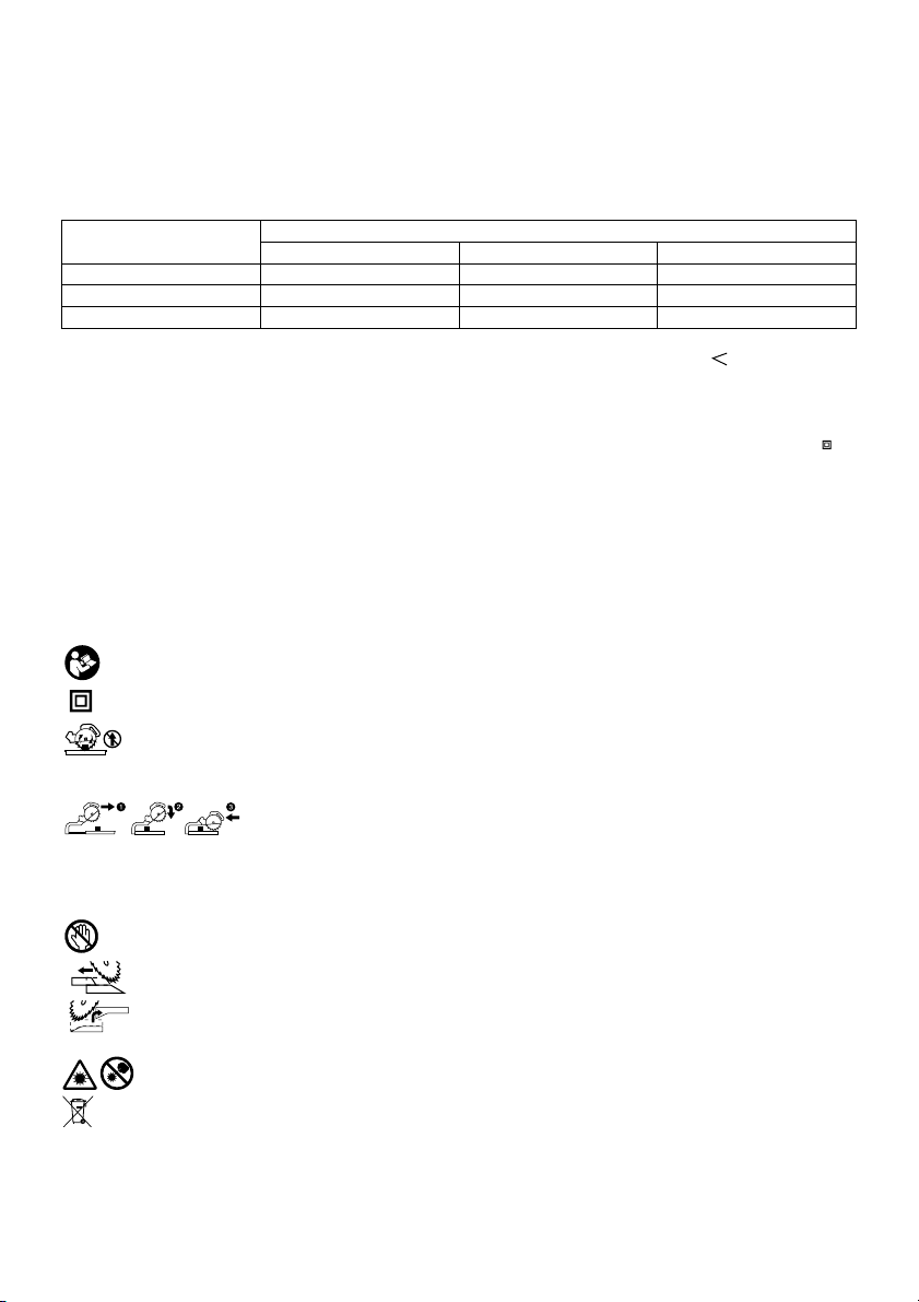
Symbols
The following show the symbols used for the equipment.
Be sure that you understand their meaning before use.
・ Read instruction manual.
・ DOUBLE INSULATION
・ To avoid injury from flying debris, keep
holding the saw head down, after
making cuts, until the blade has come
to a complete stop.
・ When performing slide cut, first pull
carriage fully and press down handle,
then push carriage toward the guide
fence.
・ Do not place hand or fingers close to
the blade.
・ Adjust sliding fences clear of blade and
blade guard properly.
・
Always remove SUB-FENCE R when
performing right bevel cuts. Failure to do
so may cause serious injury to operator.
・ Never look into the laser beam. Direct
laser beam may injure your eyes.
・ Only for EU countries
Do not dispose of electric equipment
together with household waste material!
In observance of European Directive
2002/96/EC on waste electric and
electronic equipment and its
Bevel angle
implementation in accordance with
national law, electric equipment that
have reached the end of their life must
be collected separately and returned to
an environmentally compatible
recycling facility.
ENE006-1
Intended use
The tool is intended for accurate straight and miter
cutting in wood. With appropriate saw blades, aluminum
can also be sawed.
ENF002-1
Power supply
The tool should be connected only to a power supply of
the same voltage as indicated on the nameplate, and
can only be operated on single-phase AC supply. They
are double-insulated in accordance with European
Standard and can, therefore, also be used from sockets
without earth wire.
ENG905-1
Noise
The typical A-weighted noise level determined according
to EN61029:
Sound pressure level (LpA) : 97 dB(A)
Sound power level (L
Uncertainty (K) : 3 dB(A)
) : 103 dB(A)
WA
Wear ear protection
ENG900-1
Vibration
The vibration total value (tri-axial vector sum)
determined according to EN61029:
8
Page 9
Vibration emission (a
Uncertainty (K) : 1.5 m/s
The declared vibration emission value has been
•
) : 2.5 m/s2 or less
h
2
ENG901-1
measured in accordance with the standard test
method and may be used for comparing one tool
with another.
• The declared vibration emission value may also be
used in a preliminary assessment of exposure.
WARNING:
• The vibration emission during actual use of the
power tool can differ from the declared emission
value depending on the ways in which the tool is
used.
• Be sure to identify safety measures to protect the
operator that are based on an estimation of
exposure in the actual conditions of use (taking
account of all parts of the operating cycle such as
the times when the tool is switched off and when it
is running idle in addition to the trigger time).
ENG015-2
For European countries only
Noise and Vibration
The typical A-weighted noise levels are
sound pressure level: 97 dB (A)
sound power level: 103 dB (A)
Uncertainty: 3 dB(A)
Wear ear protection.
The typical weighted root mean square acceleration
value is not more than 2.5 m/s
Uncertainty (K):1.5m/s
2
.
2
These values have been obtained according to
EN61029.
ENH003-12
For European countries only
EC Declaration of Conformity
We Makita Corporation as the responsible
manufacturer declare that the following Makita
machine(s):
Designation of Machine:
Slide Compound Miter Saw
Model No./ Type: LS1018, LS1018L
are of series production and
Conforms to the following European Directives:
2006/42/EC
And are manufactured in accordance with the following
standards or standardised documents:
EN61029
The technical documentation is kept by our authorised
representative in Europe who is:
Makita International Europe Ltd.
Michigan Drive, Tongwell,
Milton Keynes, MK15 8JD, England
6.11.2009
000230
Tomoyasu Kato
Director
Makita Corporation
3-11-8, Sumiyoshi-cho,
Anjo, Aichi, JAPAN
GEA010-1
General Power Tool Safety
Warnings
WARNING Read all safety warnings and all
instructions. Failure to follow the warnings and
instructions may result in electric shock, fire and/or
serious injury.
Save all warnings and instructions for
future reference.
ENB034-6
ADDITIONAL SAFETY RULES
FOR TOOL
1. Wear eye protection.
2. Keep hands out of path of saw blade. Avoid
contact with any coasting blade. It can still
cause severe injury.
3. Do not operate saw without guards in place.
Check blade guard for proper closing before
each use. Do not operate saw if blade guard
does not move freely and close instantly.
Never clamp or tie the blade guard into the
open position.
4. Do not perform any operation freehand. The
workpiece must be secured firmly against the turn
base and guide fence with the vise during all
operations. Never use your hand to secure the
workpiece.
5. Never reach around saw blade.
6.
Turn off tool and wait for saw blade to stop
before moving workpiece or changing
settings.
7. Unplug tool before changing blade or
servicing.
8. Always secure all moving portions before
carrying the tool.
9. Stopper pin which locks the cutter head down
is for carrying and storage purposes only and
not for any cutting operations.
10.
Do not use the tool in the presence of
flammable liquids or gases.
operation of the tool could create an explosion and
fire when exposed to flammable liquids or gases.
11. Check the blade carefully for cracks or
damage before operation.
The electrical
9
Page 10

Replace cracked or damaged blade
immediately.
12. Use only flanges specified for this tool.
13. Be careful not to damage the arbor, flanges
(especially the installing surface) or bolt.
Damage to these parts could result in blade
breakage.
14. Make sure that the turn base is properly
secured so it will not move during operation.
15.
For your safety, remove the chips, small
pieces, etc. from the table top before
operation.
16. Avoid cutting nails. Inspect for and remove all
nails from the workpiece before operation.
17. Make sure the shaft lock is released before the
switch is turned on.
18. Be sure that the blade does not contact the
turn base in the lowest position.
19. Hold the handle firmly. Be aware that the saw
moves up or down slightly during start-up and
stopping.
20. Make sure the blade is not contacting the
workpiece before the switch is turned on.
21. Before using the tool on an actual workpiece,
let it run for a while. Watch for vibration or
wobbling that could indicate poor installation
or a poorly balanced blade.
22. Wait until the blade attains full speed before
cutting.
23. Stop operation immediately if you notice
anything abnormal.
24. Do not attempt to lock the trigger in the on
position.
25. Be alert at all times, especially during
repetitive, monotonous operations. Do not be
lulled into a false sense of security. Blades are
extremely unforgiving.
26. Always use accessories recommended in this
manual. Use of improper accessories such as
abrasive wheels may cause an injury.
27. Do not use the saw to cut other than wood,
aluminum or similar materials.
28. Connect miter saws to a dust collecting device
when sawing.
29. Select saw blades in relation to the material to
be cut.
30. Take care when slotting.
31. Replace the kerf board when worn.
32. Do not use saw blades manufactured from
high speed steel.
33. Some dust created from operation contains
chemicals known to cause cancer, birth
defects or other reproductive harm. Some
examples of these chemicals are:
• lead from lead-based-painted material and,
•
arsenic and chromium from
chemically-treated lumber.
Your risk from these exposures varies,
depending on how often you do this type
of work. To reduce your exposure to these
chemicals: work in a well ventilated area
and work with approved safety equipment,
such as those dust masks that are
specially designed to filter out
microscopic particles.
34. To reduce the emitted noise, always be sure
that the blade is sharp and clean.
35. The operator is adequately trained in the use,
adjustment and operation of the machine.
36. Use correctly sharpened saw blades. Observe
the maximum speed marked on the saw blade.
37. Refrain from removing any cut-offs or other
parts of the workpiece from the cutting area
whilst the tool is running and the saw head is
not in the rest position.
38. Use only saw blades recommended by the
manufacturer which conform to EN847-1.
39. Wear gloves for handling saw blade (saw
blades shall be carried in a holder wherever
practicable) and rough material.
40. When fitted with laser, no exchange with
different type of laser is permitted. Repairs
shall only be carried out correctly.
SAVE THESE INSTRUCTIONS.
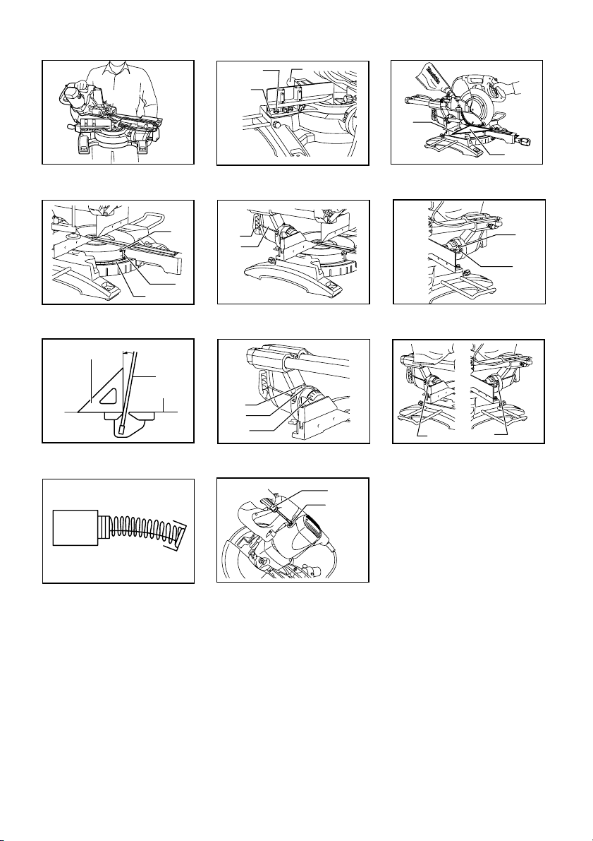
INSTALLATION
Bench mounting
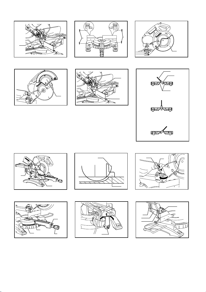
Fig.1
When the tool is shipped, the handle is locked in the
lowered position by the stopper pin. Release the stopper
pin by simultaneously applying a slight downward
pressure on the handle and pulling the stopper pin.
Fig.2
This tool should be bolted with four bolts to a level and
stable surface using the bolt holes provided in the tool's
base. This will help prevent tipping and possible injury.
FUNCTIONAL DESCRIPTION
WARNING:
• Always be sure that the tool is switched off and
unplugged before adjusting or checking
function on the tool. Failure to switch off and
unplug the tool may result in serious personal
injury from accidental start-up.
Blade guard
Fig.3
When lowering the handle, the blade guard rises
automatically. The blade guard returns to its original
position when the cut is completed and the handle is
10
Page 11

raised.
WARNING:
• Never defeat or remove the blade guard or the
spring which attaches to the guard. An exposed
blade as a result of defeated guarding may result
in serious personal injury during operation.
In the interest of your personal safety, always maintain
the blade guard in good condition. Any irregular
operation of the blade guard should be corrected
immediately. Check to assure spring loaded return
action of guard.
WARNING:
• Never use the tool if the blade guard or spring
are damaged, faulty or removed. Operation of
the tool with a damaged, faulty or removed guard
may result in serious personal injury.
If the see-through blade guard becomes dirty, or
sawdust adheres to it in such a way that the blade
and/or workpiece is no longer easily visible, unplug the
saw and clean the guard carefully with a damp cloth. Do
not use solvents or any petroleum-based cleaners on
the plastic guard because this may cause damage to the
guard.
If the blade guard becomes dirty and needs to be
cleaned for proper operation follow the steps below:
With the tool switched off and unplugged, use the
supplied socket wrench to loosen the hex bolt holding
the center cover. Loosen the hex bolt by turning it
counterclockwise and raise the blade guard and center
cover.
Fig.4
With the blade guard so positioned, cleaning can be
more completely and efficiently accomplished. When
cleaning is complete reverse procedure above and
secure bolt. Do not remove spring holding blade guard.
If guard becomes damaged through age or UV light
exposure, contact a Makita service center for a new
guard. DO NOT DEFEAT OR REMOVE GUARD.
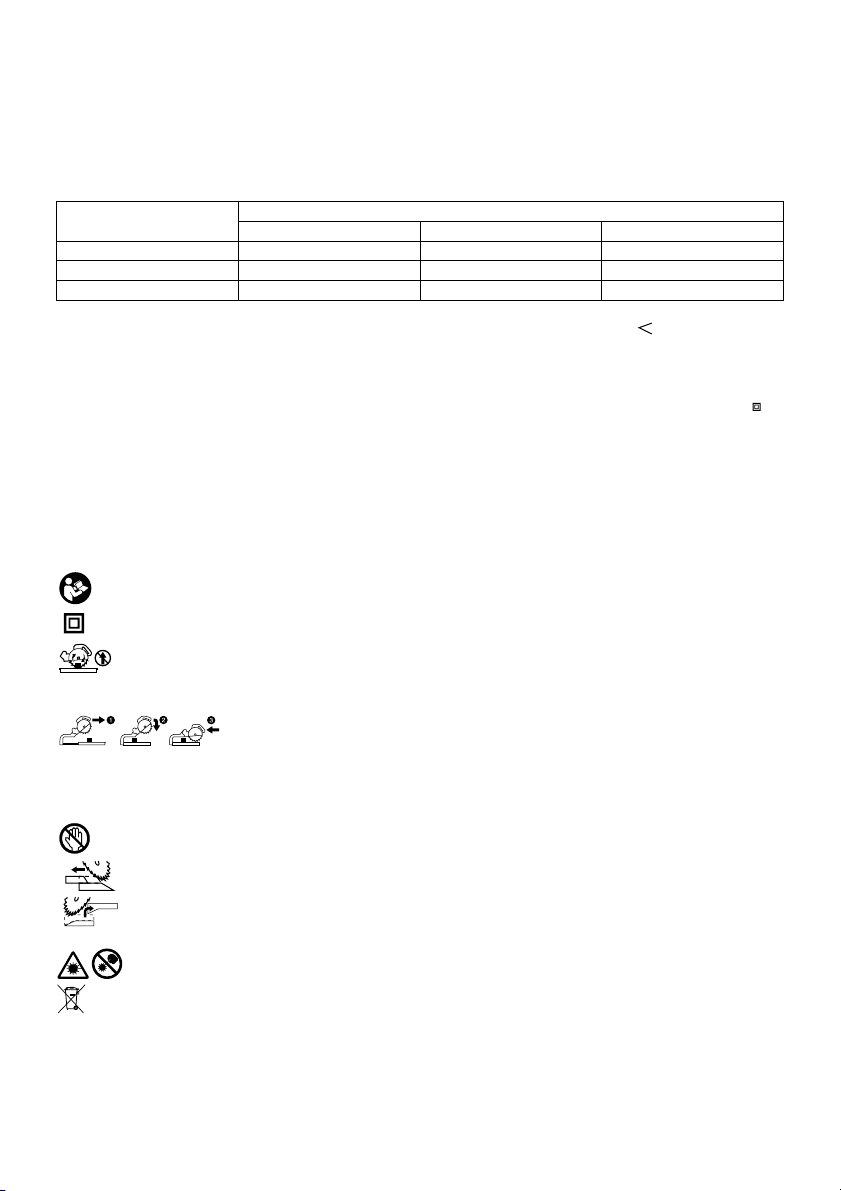
Positioning kerf board
Fig.5
Fig.6
This tool is provided with the kerf boards in the turn base
to minimize tearing on the exit side of a cut. The kerf
boards are factory adjusted so that the saw blade does
not contact the kerf boards. Before use, adjust the kerf
boards as follows:
First, unplug the tool. Loosen all the screws (3 each on
left and right) securing the kerf boards. Re-tighten them
only to the extent that the kerf boards can still be easily
moved by hand. Lower the handle fully and push in the
stopper pin to lock the handle in the lowered position.
Loosen the screw which secures the slide poles. Pull
the carriage toward you fully. Adjust the kerf boards so
that the kerf boards just contact the sides of the blade
teeth. Tighten the front screws (do not tighten firmly).
Push the carriage toward the guide fence fully and
adjust the kerf boards so that the kerf boards just
contact the sides of blade teeth. Tighten the rear screws
(do not tighten firmly).
After adjusting the kerf boards, release the stopper pin
and raise the handle. Then tighten all the screws
securely.
NOTICE:
•
After setting the bevel angle ensure that the
kerf boards are adjusted properly.
Correct
adjustment of the kerf boards will help provide
proper support of the workpiece minimizing
workpiece tear out.
Maintaining maximum cutting capacity
This tool is factory adjusted to provide the maximum
cutting capacity for a 255 mm saw blade.
Unplug the tool before any adjustment is attempted.
When installing a new blade, always check the lower
limit position of the blade and if necessary, adjust it as
follows:
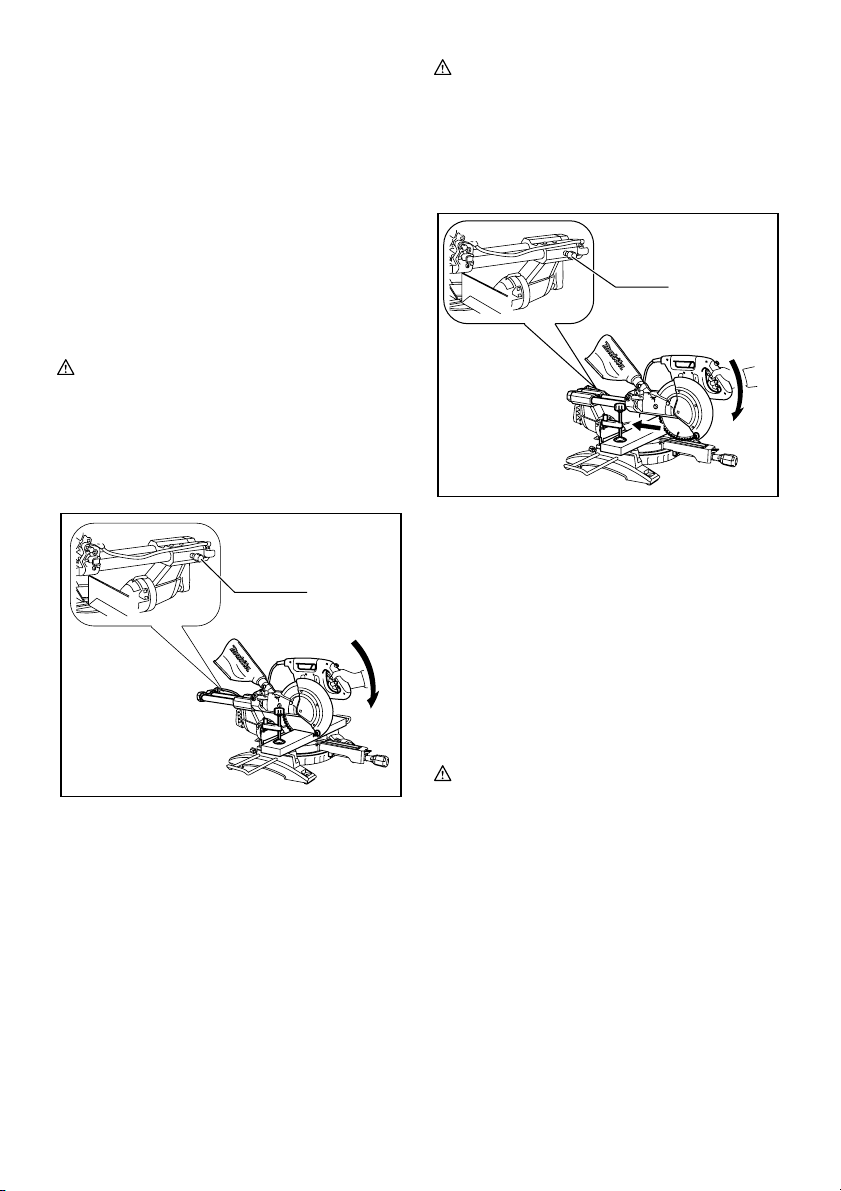
Fig.7
Fig.8
First, unplug the tool. Push the carriage toward the guide
fence fully and lower the handle completely. Use the hex.
wrench to turn the adjusting bolt until the periphery of the
blade extends slightly below the top surface of the turn
base at the point where the front face of the guide fence
meets the top surface of the turn base.
With the tool unplugged, rotate the blade by hand while
holding the handle all the way down to be sure that the
blade does not contact any part of the lower base.
Re-adjust slightly, if necessary.
WARNING:
• After installing a new blade and with the tool
unplugged, always be sure that the blade does
not contact any part of the lower base when the
handle is lowered completely. If a blade makes
contact with the base it may cause kickback and
result in serious personal injury.
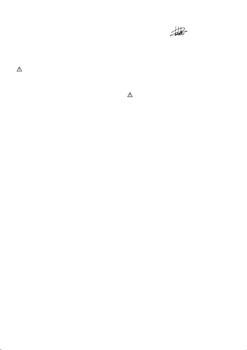
Stopper arm
Fig.9
The lower limit position of the blade can be easily
adjusted with the stopper arm. To adjust it, move the
stopper arm in the direction of the arrow as shown in the
figure. Adjust the adjusting screw so that the blade stops
at the desired position when lowering the handle fully.
Adjusting the miter angle
Fig.10
Loosen the grip by turning counterclockwise. Turn the
turn base while pressing down the lock lever. When you
have moved the grip to the position where the pointer
points to the desired angle on the miter scale, securely
tighten the grip clockwise.
11
Page 12

CAUTION:
• After changing the miter angle, always secure the
turn base by tightening the grip firmly.
NOTICE:
• When turning the turn base, be sure to raise the
handle fully.
Adjusting the bevel angle
Fig.11
To adjust the bevel angle, loosen the lever at the rear of
the tool counterclockwise. Unlock the arm by pushing
the handle somewhat strongly in the direction that you
intend to tilt the saw blade.
NOTE:
• Lever can be adjusted to a different lever angle by
removing the screw holding the lever and securing
the lever at a desired angle.
Fig.12
Tilt the saw blade until the pointer points to the desired
angle on the bevel scale. Then tighten the lever
clockwise firmly to secure the arm.
Fig.13
When tilting the carriage to the right, tilt the carriage to
the left slightly after loosening the lever and press the
releasing button. With the releasing button being
pressed, tilt the carriage to the right.
Fig.14
Tilt the saw blade until the pointer points to the desired
angle on the bevel scale. Then tighten the lever
clockwise firmly to secure the arm.
• When changing bevel angles, be sure to position
the kerf boards appropriately as explained in the
"Positioning kerf boards" section.
CAUTION:
• After changing the bevel angle, always secure the
arm by tightening the lever clockwise.
NOTICE:
• When tilting the saw blade be sure the handle is
fully raised.
• When changing bevel angles, be sure to position
the kerf boards appropriately as explained in the
"Positioning kerf boards" section.
Slide lock adjustment
Fig.15
To lock the slide pole, turn the locking screw clockwise.
Switch action
For European countries
Fig.16
To prevent the switch trigger from being accidentally
pulled, a lock-off button is provided. To start the tool,
push the lever to the left, press in the lock-off button and
then pull the switch trigger. Release the switch trigger to
stop.
WARNING:
• Before plugging in the tool, always check to
see that the switch trigger actuates properly
and returns to the "OFF" position when
released. Do not pull the switch trigger hard
without pressing in the lock-off button. This
can cause switch breakage. Operating a tool with
a switch that does not actuate properly can lead to
loss of control and serious personal injury.
A hole is provided in the switch trigger for insertion of
padlock to lock the tool off.
For all countries other than European countries
Fig.17
To prevent the switch trigger from being accidentally
pulled, a lock-off button is provided. To start the tool,
press in the lock-off button and pull the switch trigger.
Release the switch trigger to stop.
WARNING:
• Before plugging in the tool, always check to
see that the switch trigger actuates properly
and returns to the "OFF" position when
released. Do not pull the switch trigger hard
without pressing in the lock-off button. This
can cause switch breakage. Operating a tool with
a switch that does not actuate properly can lead to
loss of control and serious personal injury.
A hole is provided in the switch trigger for insertion of
padlock to lock the tool off.
WARNING:
• Do not use a lock with a shank or cable any
smaller than 6.35 mm in diameter. A smaller
shank or cable may not properly lock the tool in the
off position and unintentional operation may occur
resulting in serious personal injury.
• NEVER use tool without a fully operative
switch trigger. Any tool with an inoperative switch
is HIGHLY DANGEROUS and must be repaired
before further usage or serious personal injury may
occur.
• For your safety, this tool is equipped with a lock-off
button which prevents the tool from unintended
starting. NEVER use the tool if it runs when you
simply pull the switch trigger without pressing the
lock-off button. A switch in need of repair may
result in unintentional operation and serious
personal injury. Return tool to a Makita service
center for proper repairs BEFORE further usage.
• NEVER defeat the lock-off button by taping down
or some other means. A switch with a defeated
lock-off button may result in unintentional operation
and serious personal injury.
12
Page 13
Electronic function
x
Soft start feature
• This function allows the smooth start-up of the tool
by limiting the start-up torque.
Laser beam action
For model LS1018L only
NOTE:
• Before the first use, install two AA dry cells in the
cell box. Refer to the section titled "Replacing the
dry cells for laser unit" for the installment.
CAUTION:
• When not in use, be sure to turn off the laser
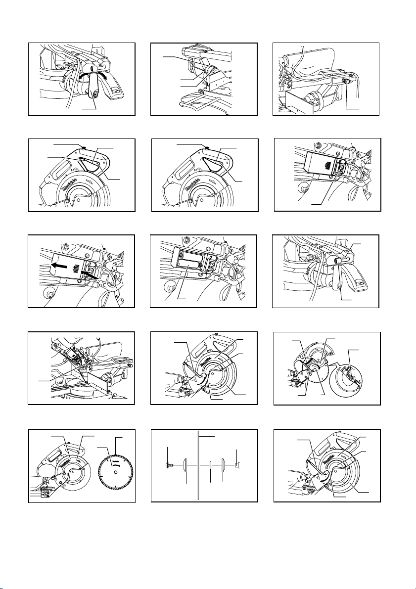
Fig.18
CAUTION:
• Never look into the laser beam. Direct laser beam
may injure your eyes.
• LASER RADIATION, DO NOT STARE INTO THE
BEAM, CLASS 2 LASER PRODUCT.
•
Before shifting the laser line or performing
maintenance adjustment, be sure to unplug the
tool.
To turn on the laser beam, press the upper position (I) of
the switch. To turn off the laser beam, press the lower
position (0) of the switch.
Laser line can be shifted to either the left or right side of
the saw blade by loosening the screw holding the laser
unit box and shifting it in the desired direction. After
shifting, be sure to tighten the screw.
1
1. Screw holding the laser unit bo
010473
Laser line is factory adjusted so that it is positioned
within 1 mm from the side surface of the blade (cutting
position).
NOTE:
• When laser line appears dim and hard to see
because of direct sunlight, relocate the work area
to a place where there is less direct sunlight.
Replacing the dry cells for laser unit
Fig.19
Fig.20
Remove the lid for the dry cells for laser unit by sliding
while pressing it. Take out the old dry cells and put the
new ones as shown in the figure. After replacing, return
the lid to cover it.
Cleaning of the lens for the laser light
If the lens for the laser light becomes dirty, or sawdust
adheres to it in such a way that the laser line is no longer
easily visible, unplug the saw and remove and clean the
lens for the laser light carefully with a damp, soft cloth.
Do not use solvents or any petroleum-based cleaners on
the lens.
NOTE:
• When laser line is dim and almost or entirely
invisible because of the direct sunlight in the indoor
or outdoor window-by work, relocate the work area
to a place not exposed to the direct sunlight.
ASSEMBLY
WARNING:
• Always be sure that the tool is switched off and
unplugged before working on the tool. Failure to
switch off and unplug the tool may result in serious
personal injury.
Storage of socket wrench with hex wrench on
its other end
Fig.21
The socket wrench is stored as shown in the figure.
When the socket wrench is needed it can be pulled out
of the wrench holder. After using the socket wrench it
can be stored by returning it to the wrench holder.
Installing or removing saw blade
WARNING:
• Always be sure that the tool is switched off and
unplugged before installing or removing the
blade. Accidental start up of the tool may result in
serious personal injury.
• Use only the Makita socket wrench provided to
install or remove the blade.Failure to use the
wrench may result in overtightening or insufficient
tightening of the hex bolt and serious personal
injury.
Fig.22
Lock the handle in the raised position by pushing in the
stopper pin.
Fig.23
To remove the blade, use the socket wrench to loosen
the hex bolt holding the center cover by turning it
counterclockwise. Raise the blade guard and center
cover.
13
Page 14
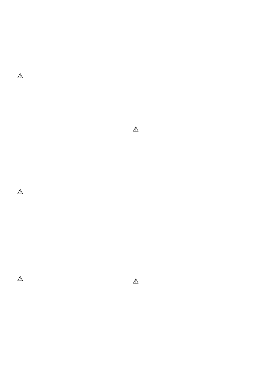
Fig.24
Press the shaft lock to lock the spindle and use the
socket wrench to loosen the hex bolt clockwise. Then
remove the hex bolt, outer flange and blade.
NOTE:
• If the inner flange is removed be sure to install it on
the spindle with its protrusion facing away from the
blade. If the flange is installed incorrectly the
flange will rub against the machine.
WARNING:
• Before mounting the blade onto the spindle,
always be sure that the correct ring for the
blade's arbor hole you intend to use is installed
between the inner and the outer flanges. Use of
the incorrect arbor hole ring may result in the
improper mounting of the blade causing blade
movement and severe vibration resulting in
possible loss of control during operation and in
serious personal injury.
Fig.25
To install the blade, mount it carefully onto the spindle,
making sure that the direction of the arrow on the
surface of the blade matches the direction of the arrow
on the blade case.
Install the outer flange and hex bolt, and then use the
socket wrench to tighten the hex bolt (left-handed)
securely counterclockwise while pressing the shaft lock.
For all countries other than European countries
Fig.26
WARNING:
•
The black ring 25 mm in outer diameter and the
silver ring 25.4 mm in outer diameter are
factory-installed as shown in the figure. When using
a blade with 25 mm hole diameter, replace the silver
ring with the black ring.
Before mounting the blade
onto the spindle, always be sure that the correct
ring for the blade's arbor hole you intend to use
is installed between the inner and the outer
flanges.
Use of the incorrect arbor hole ring may
result in the improper mounting of the blade causing
blade movement and severe vibration resulting in
possible loss of control during operation and in
serious personal injury.
For European countries
CAUTION:
•
The ring 30 mm in outer diameter is factory-installed
between the inner and outer flanges.
Install the outer flange and hex bolt, and then use the
socket wrench to tighten the hex bolt securely
counterclockwise while pressing the shaft lock.
Fig.27
Return the blade guard and center cover to its original
position. Then tighten the hex bolt clockwise to secure the
center cover. Release the handle from the raised position
by pulling the stopper pin. Lower the handle to make sure
that the blade guard moves properly. Make sure the shaft
lock has released spindle before making cut.
Dust bag (accessory)
Fig.28
The use of the dust bag makes cutting operations
cleaner and dust collection easier. To attach the dust
bag, fit it onto the dust nozzle.
When the dust bag is about half full, remove the dust
bag from the tool and pull the fastener out. Empty the
dust bag of its contents, tapping it lightly so as to remove
particles adhering to the insides which might hamper
further collection.
NOTE:
If you connect a vacuum cleaner to your saw, cleaner
operations can be performed.
Securing workpiece
WARNING:
• It is extremely important to always secure the
workpiece correctly with the proper type of
vise or crown molding stoppers. Failure to do so
may result in serious personal injury and cause
damage to the tool and/or the workpiece.
• After a cutting operation do not raise the blade
until it has come to a complete stop. The raising
of a coasting blade may result in serious personal
injury and damage to the workpiece.
•
When cutting a workpiece that is longer than
the support base of the saw, the material
should be supported the entire length beyond
the support base and at the same height to
keep the material level.
Proper workpiece
support will help avoid blade pinch and possible
kickback which may result in serious personal
injury. Do not rely solely on the vertical vise and/or
horizontal vise to secure the workpiece. Thin
material tends to sag. Support workpiece over its
entire length to avoid blade pinch and possible
KICKBACK.
Fig.29
Guide fence (SLIDING FENCES which are
upper and lower fences) adjustment
Fig.30
WARNING:
• Before operating the tool, make sure that the
sliding fence is secured firmly.
• Before bevel-cutting, make sure that no part of
the tool, especially the blade, contacts the
upper and lower fences when fully lowering
and raising the handle in any position and
while moving the carriage through its full range
of travel. If the tool or blade makes contact with
the fence this may result in kickback or unexpected
14
Page 15

movement of the material and serious personal
injury.
Fig.31
CAUTION:
•
When performing bevel cuts, slide the sliding
fence to the left and secure it as shown in the
figure. Otherwise, it will contact the blade or a part
of the tool, causing possible serious injury to the
operator.
This tool is equipped with the sliding fence which should
ordinarily be positioned as shown in the figure.
However, when performing left bevel cuts, set it to the left
position as shown in the figure if the tool head contacts it.
When bevel-cutting operations are complete, don't
forget to return the sliding fence to the original position
and secure it by firmly tightening the clamping screw.
Sub-fence R
WARNING:
• Before operating the tool, make sure that the
sub-fence R is secured firmly.
•
Before performing right bevel cuts, remove the
sub-fence R. It will contact the blade or a part of
the tool, causing possible serious injury to the
operator.
Fig.32
The sub-fence R can be removed from the right side of
the guide fence. To remove the sub-fence R, loosen the
screw which secures the sub-fence R and pull it out.
Follow the removal procedure in reverse to install it.
When bevel-cutting operations are complete, don't
forget to return the sub-fence R to the original position
and secure it by firmly tightening the clamping screw.
Vertical vise
Fig.33
The vertical vise can be installed on either the left or
right side of the guide fence. Insert the vise rod into the
hole in the guide fence and tighten the screw on the
back of the guide fence to secure the vise rod.
Position the vise arm according to the thickness and
shape of the workpiece and secure the vise arm by
tightening the screw. If the screw to secure the vise arm
contacts the guide fence, install the screw on the
opposite side of vise arm. Make sure that no part of the
tool contacts the vise when lowering the handle fully and
pulling or pushing the carriage all the way. If some part
contacts the vise, re-position the vise.
Press the workpiece flat against the guide fence and the
turn base. Position the workpiece at the desired cutting
position and secure it firmly by tightening the vise knob.
WARNING:
• The workpiece must be secured firmly against
the turn base and guide fence with the vise
during all operations. If the workpiece is not
properly secured against the fence the material
may move during the cutting operation causing
possible damage to the blade, causing the material
to be thrown and loss of control resulting in serious
personal injury.
Horizontal vise (optional accessory)
Fig.34
The horizontal vise can be installed in two positions on
either the left or right side of the base. When performing
10° or greater miter cuts, install the horizontal vise on
the side opposite the direction in which the turn base is
to be turned.
Fig.35
By flipping the vise nut counterclockwise, the vise is
released, and rapidly moves in and out. To grip the
workpiece, push the vise knob forward until the vise
plate contacts the workpiece and flip the vise nut
clockwise. Then turn the vise knob clockwise to secure
the workpiece.
The maximum width of workpiece which can be secured
by the horizontal vise is 215 mm.
When installing the horizontal vise on the right side of
the base, also use the sub-fence R to secure the
workpiece more firmly. Refer to the "Sub-fence R"
section described on previously for installing the
sub-fence R.
WARNING:
•
Always rotate the vise nut clockwise until the
workpiece is properly secured.
If the workpiece
is not properly secured the material may move
during the cutting operation causing possible
damage to the blade, causing the material to be
thrown and loss of control resulting in serious
personal injury.
•
When cutting a thin workpiece, such as base
boards, against the fence, always use the
horizontal vise.
Holders
Fig.36
The holders can be installed on either side as a
convenient means of holding workpieces horizontally.
Slip fully the holder rods into the holes in the base. Then
tighten the holders securely with the screws.
WARNING:
• Always support a long workpiece so it is level
with the top surface of the turn base for an
accurate cut and to prevent dangerous loss of
tool control. Proper workpiece support will help
avoid blade pinch and possible kickback which
may result in serious personal injury.
OPERATION
NOTICE:
• Before use, be sure to release the handle from the
lowered position by pulling the stopper pin.
15
Page 16
• Do not apply excessive pressure on the handle
when cutting. Too much force may result in
overload of the motor and/or decreased cutting
efficiency. Push down handle with only as much
force as is necessary for smooth cutting and
without significant decrease in blade speed.
• Gently press down the handle to perform the cut. If
the handle is pressed down with force or if lateral
force is applied, the blade will vibrate and leave a
mark (saw mark) in the workpiece and the
precision of the cut will be impaired.
• During a slide cut, gently push the carriage toward
the guide fence without stopping. If the carriage
movement is stopped during the cut, a mark will be
left in the workpiece and the precision of the cut
will be impaired.
WARNING:
• Make sure the blade is not contacting the
workpiece, etc. before the switch is turned on.
Turning the tool on with the blade in contact with
the workpiece may result in kickback and serious
personal injury.
1. Press cutting (cutting small workpieces)
1
1. Locking screw
011409
Workpieces up to 91 mm high and 70 mm wide can
be cut in the following manner.
Push the carriage toward the guide fence fully and
tighten the locking screw clockwise to secure the
carriage. Secure the workpiece correctly with the
proper type of vise. Switch on the tool without the
blade making any contact and wait until the blade
attains full speed before lowering. Then gently
lower the handle to the fully lowered position to cut
the workpiece. When the cut is completed, switch
off the tool and WAIT UNTIL THE BLADE HAS
COME TO A COMPLETE STOP before returning
the blade to its fully elevated position.
WARNING:
• Firmly tighten the knob clockwise so that the
carriage will not move during operation.
Insufficient tightening of the knob may cause
possible kickback which may result in serious
personal injury.
2. Slide (push) cutting (cutting wide workpieces)
1
1. Locking screw
011410
Loosen the locking screw counterclockwise so that
the carriage can slide freely. Secure the workpiece
with the proper type of vise. Pull the carriage
toward you fully. Switch on the tool without the
blade making any contact and wait until the blade
attains full speed. Press the handle down and
PUSH THE CARRIAGE TOWARD THE GUIDE
FENCE AND THROUGH THE WORKPIECE.
When the cut is completed, switch off the tool and
WAIT UNTIL THE BLADE HAS COME TO A
COMPLETE STOP before returning the blade to its
fully elevated position.
WARNING:
• Whenever performing a slide cut, first pull the
carriage full towards you and press the handle
all the way down, then push the carriage
toward the guide fence. Never start the cut with
the carriage not pulled fully toward you. If you
perform the slide cut without the carriage pulled
fully toward you unexpected kickback may occur
and serious personal injury may result.
• Never attempt to perform a slide cut by pulling
the carriage towards you. Pulling the carriage
towards you while cutting may cause unexpected
kickback resulting in possible serious personal
injury.
• Never perform the slide cut with the handle locked
in the lowered position.
• Never loosen the locking screw which secures
the carriage while the blade is rotating. A loose
16
Page 17
carriage while cutting may cause unexpected
kickback resulting in possible in serious personal
injury.
3. Miter cutting
Refer to the previously covered "Adjusting the
miter angle".
4. Bevel cut
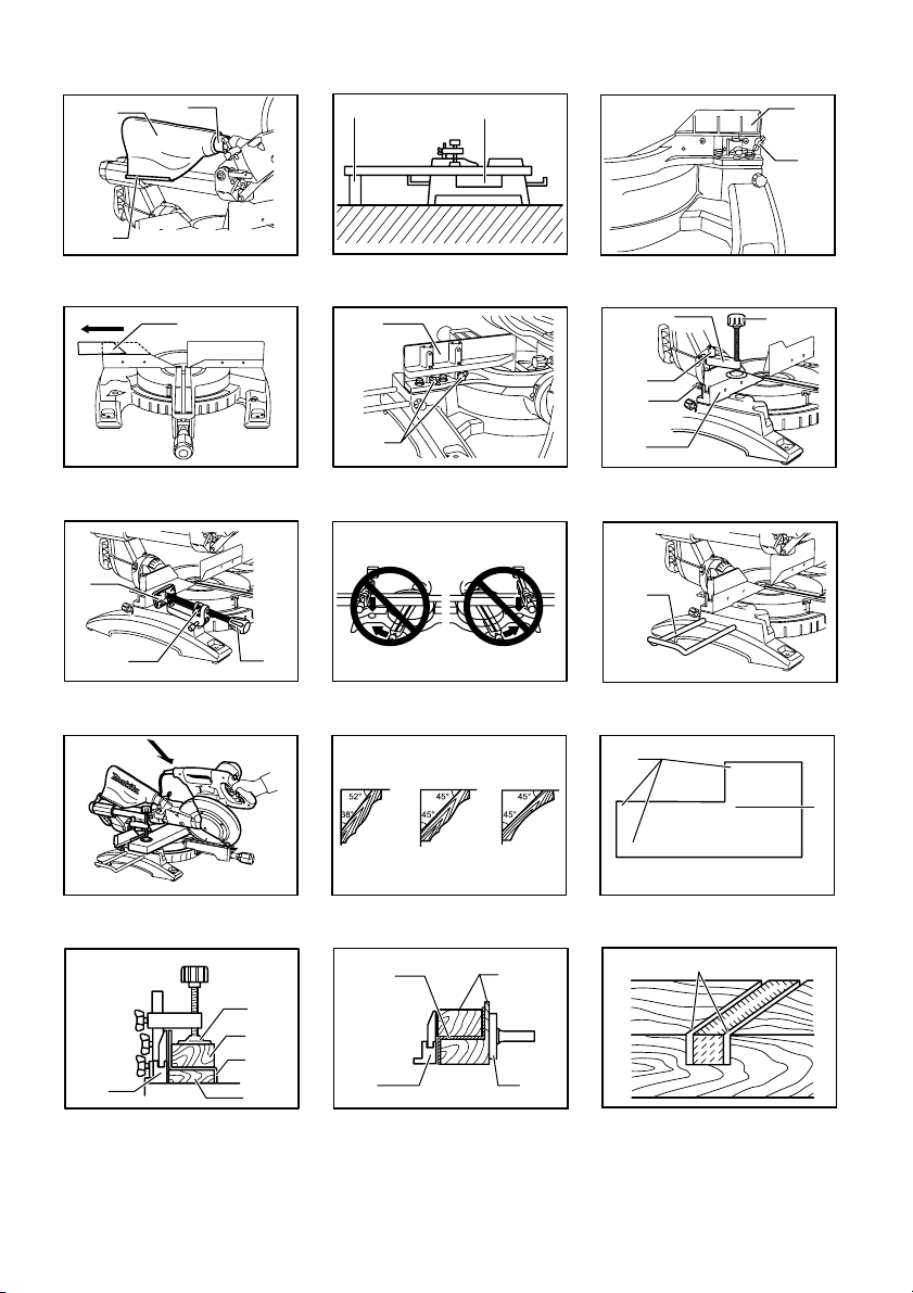
Fig.37
Loosen the lever and tilt the saw blade to set the
bevel angle (Refer to the previously covered
"Adjusting the bevel angle"). Be sure to retighten
the lever firmly to secure the selected bevel angle
safely. Secure the workpiece with a vise. Make
sure the carriage is pulled all the way back toward
the operator. Switch on the tool without the blade
making any contact and wait until the blade attains
full speed. Then gently lower the handle to the fully
lowered position while applying pressure in parallel
with the blade and PUSH THE CARRIAGE
TOWARD THE GUIDE FENCE TO CUT THE
WORKPIECE. When the cut is completed, switch
off the tool and WAIT UNTIL THE BLADE HAS
COME TO A COMPLETE STOP before returning
the blade to its fully elevated position.
WARNING:
• After setting the blade for a bevel cut, before
operating the tool ensure that the carriage and
blade will have free travel throughout the entire
range of the intended cut. Interruption of the
carriage or blade travel during the cutting operation
may result in kickback and serious personal injury.
• While making a bevel cut keep hands out of the
path of the blade. The angle of the blade may
confuse the operator as to the actual blade path
while cutting and contact with the blade will result
in serious personal injury.
• The blade should not be raised until it has
come to a complete stop. During a bevel cut the
piece cut off may come to rest against the blade.
If the blade is raised while it is rotating the cut-off
piece maybe ejected by the blade causing the
material to fragment which may result in serious
personal injury.
NOTICE:
• When pressing down the handle, apply pressure in
parallel with the blade. If a force is applied
perpendicularly to the turn base or if the pressure
direction is changed during a cut, the precision of
the cut will be impaired.
• Before bevel-cutting, an adjustment of the upper
fence and lower fence maybe required. Refer to
the section titled "Guide fence adjustment".
CAUTION:
• Always remove the sub-fence R so that it does not
interfere any part of the carriage when performing
right bevel cuts.
5. Compound cutting
Compound cutting is the process in which a bevel
angle is made at the same time in which a miter
angle is being cut on a workpiece. Compound
cutting can be performed at the angle shown in the
table.
Miter angle Bevel angle
Left and Right 0 - 45
009713
Left and Right 0 - 45
When performing compound cutting, refer to
"Press cutting", "Slide cutting", "Miter cutting" and
"Bevel cut" explanations.
6. Cutting crown and cove moldings
Crown and cove moldings can be cut on a
compound miter saw with the moldings laid flat on
the turn base.
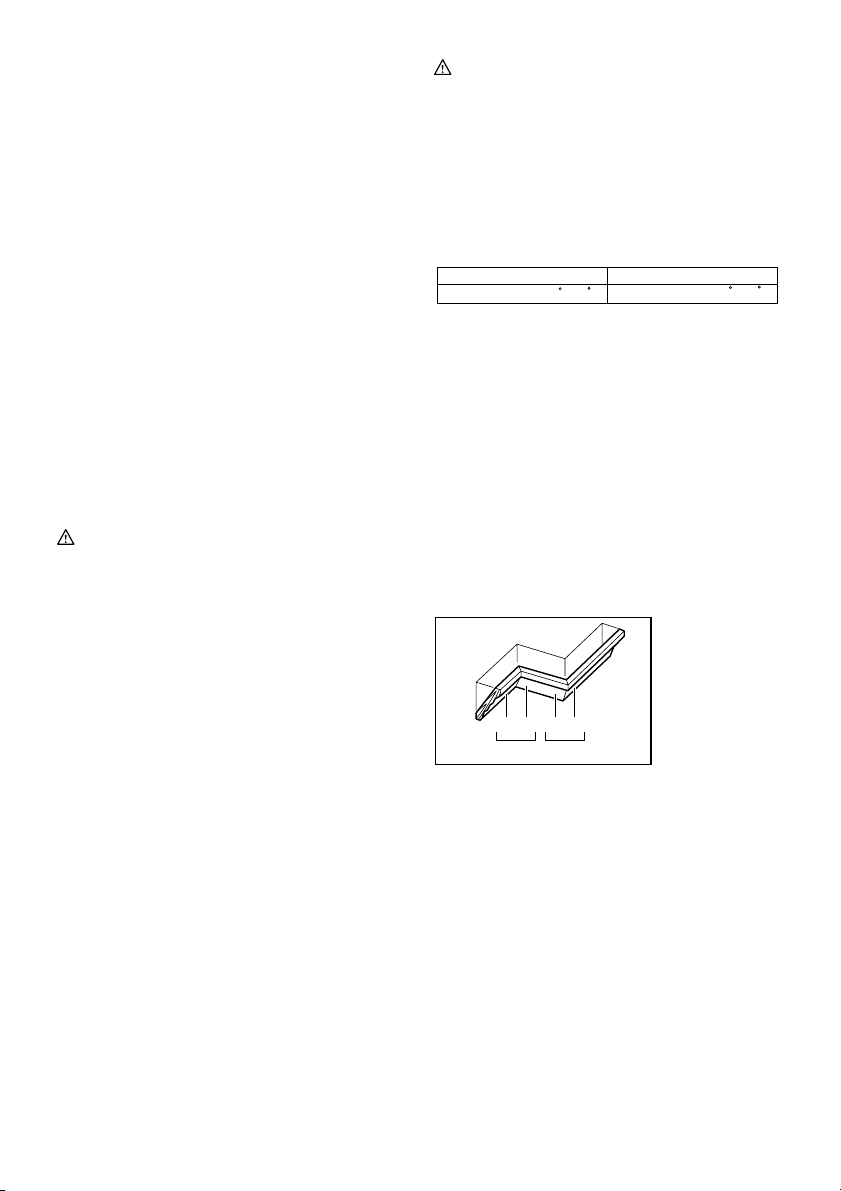
There are two common types of crown moldings
and one type of cove moldings; 52/38° wall angle
crown molding, 45° wall angle crown molding and
45° wall angle cove molding. See illustrations.
Fig.38
There are crown and cove molding joints which are
made to fit "Inside" 90° corners ((1) and (2) in Fig.
A) and "Outside" 90° corners ((3) and (4) in Fig. A).
1. Inside corner
2. Outside corner
(1) (2) (3)(4)
Fig.A
001556
1 2
Fig.39
Measuring
Measure the wall length and adjust workpiece on
table to cut wall contact edge to desired length.
Always make sure that cut workpiece length
back of the workpiece
is the same as wall length.
at the
Adjust cut length for angle of cut. Always use
several pieces for test cuts to check the saw
angles.
When cutting crown and cove moldings, set the
bevel angle and miter angle as indicated in the
table (A) and position the moldings on the top
surface of the saw base as indicated in the table
(B).
17
Page 18
In the case of left bevel cut
Table (A)
Bevel angleMiter angle
52/38° type 45° type
Left 33.9° Left 30°
For inside
corner
For outside
corner
006361
Molding
position in
Fig. A
(1)
(2)
(3)
(4)
Table (B)
Molding
Molding edge against
position in
guide fence
Fig. A
Ceiling contact edge should
(1)
For inside
corner
For
outside
corner
006362
be against guide fence.
(2)
Wall contact edge should be
against guide fen
(3)
Ceiling contact edge should
(4)
be against guide fen
Example:
In the case of cutting 52/38° type crown
molding for position (1) in Fig. A:
• Tilt and secure bevel angle setting to
33.9° LEFT.
• Adjust and secure miter angle setting to
31.6° RIGHT.
• Lay crown molding with its broad back
(hidden) surface down on the turn base
with its CEILING CONTACT EDGE
against the guide fence on the saw.
• The finished piece to be used will
always be on the LEFT side of the blade
after the cut has been made.
In the case of right bevel cut
Table (A)
Bevel angleMiter angle
52/38° type 45° type
Right 33.9° Right 30°
For inside
corner
For outside
corner
006363
Molding
position in
Fig. A
(1)
(2)
(3)
(4)
Table (B)
Molding
Molding edge against
position in
guide fence
Fig. A
Wall contact edge should be
(1)
agains
For inside
corner
For
outside
corner
006364
(2)
(3)
(4)
t guide fence.
Ceiling contact edge should
be against guide fence.
Wall contact edge should be
against guide fence.
52/38° type
Right 31.6°
Left 31.6° Left 35.3°
ce.
ce.
52/38° type
Right 31.6°
Left 31.6° Left 35.3°
45° type
Right 35.3°
Right 35.3°Right 31.6°
Finished piece
Finished piece
will be on the
Left side of
blade.
Finished piece
will be on the
Right side of
blade.
45° type
Right 35.3°
Right 35.3°Right 31.6°
Finished piece
Finished piece
will be on the
Right side of
blade.
Finished piece
will be on the
Left side of
blade.
Example:
In the case of cutting 52/38° type crown
molding for position (1) in Fig. A:
• Tilt and secure bevel angle setting to
33.9° RIGHT.
• Adjust and secure miter angle setting to
31.6° RIGHT.
• Lay crown molding with its broad back
(hidden) surface down on the turn base
with its WALL CONTACT EDGE against
the guide fence on the saw.
• The finished piece to be used will
always be on the RIGHT side of the
blade after the cut has been made.
7. Cutting aluminum extrusion
Fig.40
Fig.41
When securing aluminum extrusions, use spacer
blocks or pieces of scrap as shown in the figure to
prevent deformation of the aluminum. Use a
cutting lubricant when cutting the aluminum
extrusion to prevent build-up of the aluminum
material on the blade.
WARNING:
• Never attempt to cut thick or round aluminum
extrusions. Thick or round aluminum extrusions
can be difficult to secure and may work loose
during the cutting operation which may result in
loss of control and serious personal injury.
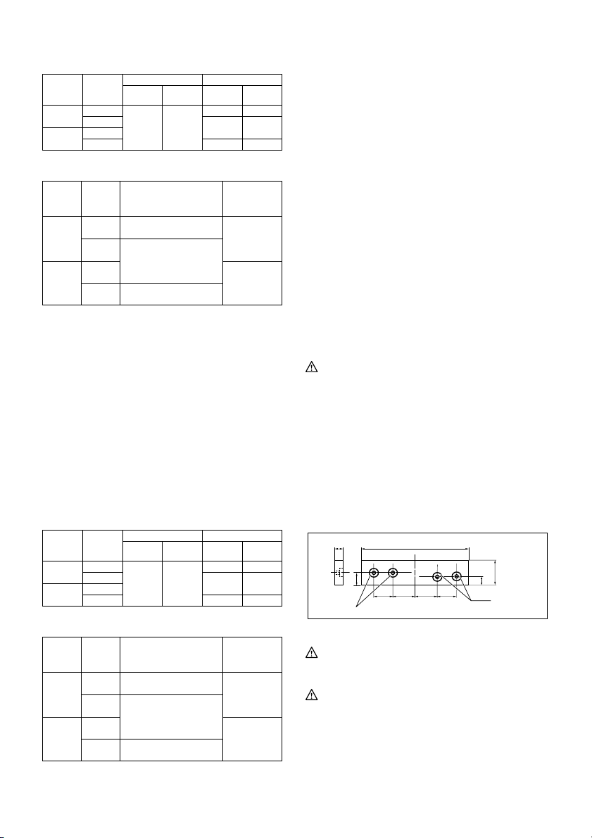
8. Wood facing
Use of wood facing helps to assure splinter-free
cuts in workpieces. Attach a wood facing to the
guide fence using the holes in the guide fence.
See the figure concerning the dimensions for a
suggested wood facing.
15mm Over 500 mm
1. Holes
010563
24 mm
1
68mm 121mm
121mm
20 mm
68mm
CAUTION:
• Use straight wood of even thickness as the wood
facing.
WARNING:
• Use screws to attach the wood facing to the
guide fence. The screws should be installed
so that the screw heads are below the surface
of the wood facing so that they will not
interfere with the positioning of the material
80mm-90mm
1
18
Page 19

being cut. Misalignment of the material being cut
can case unexpected movement during the
cutting operation which may result in a loss of
control and serious personal injury.
NOTICE:
• When the wood facing is attached, do not turn the
turn base with the handle lowered. The blade
and/or the wood facing will be damaged.
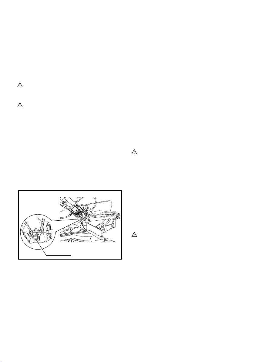
9. Groove cutting
Fig.42
A dado type cut can be made by proceeding as
follows:
Adjust the lower limit position of the blade using
the adjusting screw and the stopper arm to limit the
cutting depth of the blade. Refer to "Stopper arm"
section described previously.
After adjusting the lower limit position of the blade,
cut parallel grooves across the width of the
workpiece using a slide (push) cut as shown in the
figure. Then remove the workpiece material
between the grooves with a chisel.
WARNING:
• Do not attempt to perform this type of cut by
using a wider type blade or dado blade.
Attempting to make a groove cut with a wider blade
or dado blade could lead to unexpected cutting
results and kickback which may result in serious
personal injury
• Be sure to return the stopper arm to the
original position when performing other than
groove cutting. Attempting to make cuts with the
stopper arm in the incorrect position could lead to
unexpected cutting results and kickback which
may result in serious personal injury.
CAUTION:
•
Be sure to return the stopper arm to the original
position when performing other than groove
cutting.
Carrying tool
Fig.43
Make sure that the tool is unplugged. Secure the blade
at 0° bevel angle and the turn base at the full right miter
angle position. Secure the slide poles so that the lower
slide pole is locked in the position of the carriage fully
pulled to operator and the upper poles are locked in the
position of the carriage fully pushed forward to the guide
fence (refer to the section titled "Slide lock adjustment ".)
Lower the handle fully and lock it in the lowered position
by pushing in the stopper pin.
Wind the power supply cord using the cord rests.
WARNING:
• Stopper pin is only for carrying and storage
purposes and should never be used for any
cutting operations. The use of the stopper pin for
cutting operations may cause unexpected
movement of the saw blade resulting in kickback
and serious personal injury.
Carry the tool by holding both sides of the tool base as
shown in the figure. If you remove the holders, dust bag,
etc., you can carry the tool more easily.
CAUTION:
• Always secure all moving portions before carrying
the tool. If portions of the tool move or slide while
being carried loss of control or balance may occur
resulting in personal injury.
MAINTENANCE
WARNING:
•
Always be sure that the tool is switched off
and unplugged before attempting to perform
inspection or maintenance.
and switch off the tool may result in accidental
start up of the tool which may result in serious
personal injury.
•
Always be sure that the blade is sharp and
clean for the best and safest performance.
Attempting a cut with a dull and /or dirty blade may
cause kickback and result in a serious personal
injury.
NOTICE:
• Never use gasoline, benzine, thinner, alcohol or
the like. Discoloration, deformation or cracks may
result.
Adjusting the cutting angle
This tool is carefully adjusted and aligned at the factory,
but rough handling may have affected the alignment. If
your tool is not aligned properly, perform the following:
1. Miter angle
Fig.44
Push the carriage toward the guide fence and
tighten the locking screw to secure the carriage.
Loosen the grip which secures the turn base. Turn
the turn base so that the pointer points to 0° on the
miter scale. Then turn the turn base slightly
clockwise and counterclockwise to seat the turn
base in the 0° miter notch. (Leave as it is if the
pointer does not point to 0°.) Loosen the hex
sockets bolts securing the guide fence using the
socket wrench.
Fig.45
Lower the handle fully and lock it in the lowered
position by pushing in the stopper pin. Square the
side of the blade with the face of the guide fence
using a triangular rule, try-square, etc. Then
securely tighten the hex socket bolts on the guide
fence in order starting from the right side.
19
Failure to unplug
Page 20
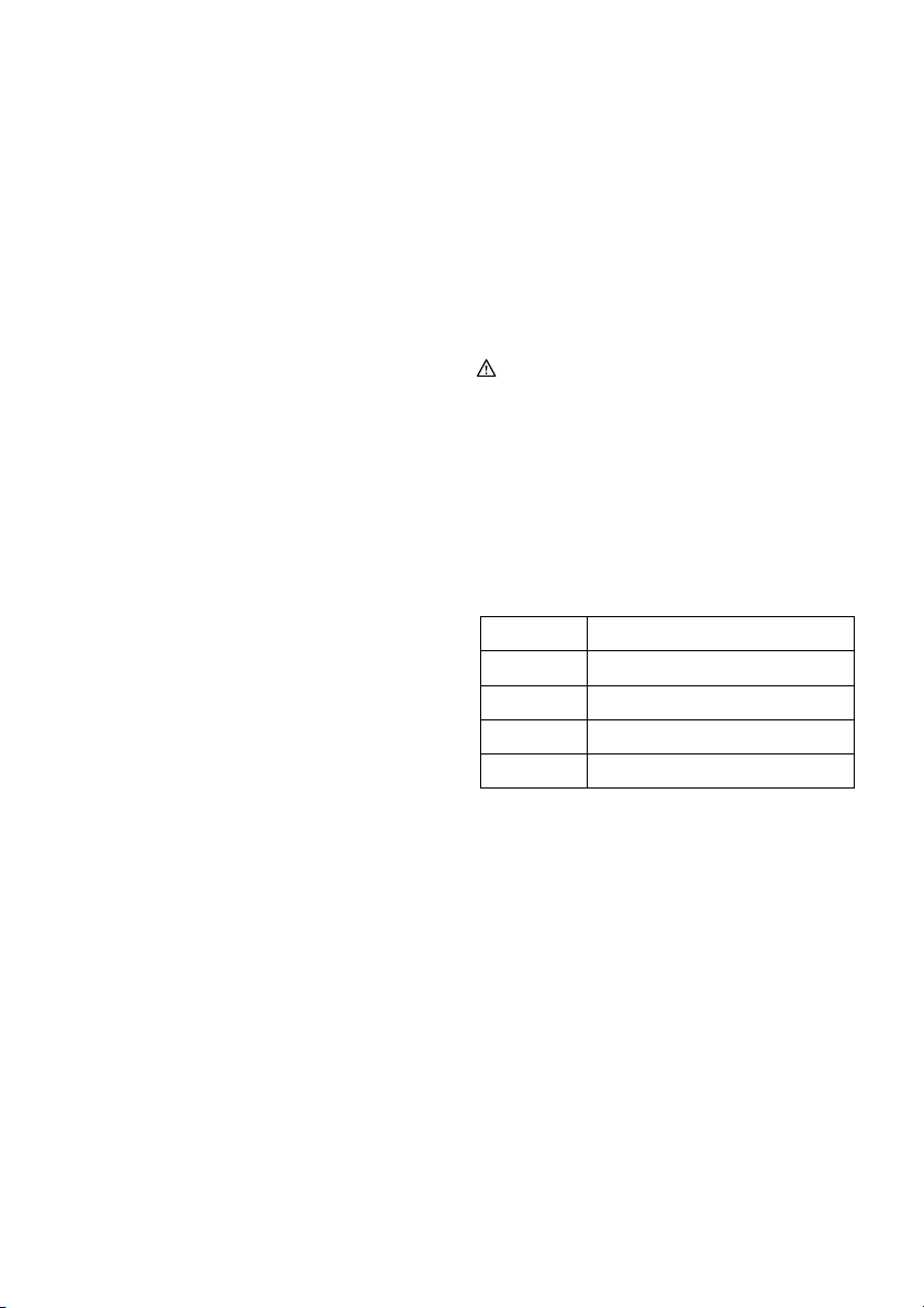
Fig.46
Make sure that the pointer points to 0° on the miter
scale. If the pointer does not point to 0°, loosen the
screw which secures the pointer and adjust the
pointer so that it will point to 0°.
2. Bevel angle
(1) 0° bevel angle
Fig.47
Push the carriage toward the guide fence
and tighten the locking screw to secure the
carriage. Lower the handle fully and lock it in
the lowered position by pushing in the
stopper pin. Loosen the lever at the rear of
the tool.
Fig.48
Turn the hex bolt on the right side of the arm
two or three revolutions counterclockwise to
tilt the blade to the right.
Fig.49
Carefully square the side of the blade with
the top surface of the turn base using the
triangular rule, try-square, etc. by turning the
hex bolt on the right side of the arm clockwise.
Then tighten the lever securely.
Fig.50
Make sure that the pointer on the arm point to
0° on the bevel scale on the arm holder. If
they do not point to 0°, loosen the screw
which secure the pointer and adjust it so that
it will point to 0°.
(2) 45° bevel angle
Fig.51
Adjust the 45° bevel angle only after
performing 0° bevel angle adjustment. To
adjust left 45° bevel angle, loosen the lever
and tilt the blade to the left fully. Make sure
that the pointer on the arm points to 45° on
the bevel scale on the arm holder. If the
pointer does not point to 45°, turn the 45°
bevel angle adjusting bolt on the right side of
the arm holder until the pointer points to 45°.
To adjust the right 45° bevel angle, perform
the same procedure as that described above.
Fig.52
Remove and check the carbon brushes regularly.
Replace when they wear down to 3 mm in length. Keep
the carbon brushes clean and free to slip in the holders.
Both carbon brushes should be replaced at the same
time. Use only identical carbon brushes.
Fig.53
Use a screwdriver to remove the brush holder caps.
Take out the worn carbon brushes, insert the new ones
and secure the brush holder caps.
After use
• After use, wipe off chips and dust adhering to the
tool with a cloth or the like. Keep the blade guard
clean according to the directions in the previously
covered section titled "Blade guard". Lubricate the
sliding portions with machine oil to prevent rust.
• When storing the tool, pull the carriage toward you
fully.
To maintain product SAFETY and RELIABILITY, repairs,
any other maintenance or adjustment should be
performed by Makita Authorized Service Centers,
always using Makita replacement parts.
OPTIONAL ACCESSORIES
WARNING:
• These Makita accessories or attachments are
recommended for use with your Makita tool
specified in this manual. The use of any other
accessories or attachments may result in serious
personal injury.
• Only use the Makita accessory or attachment
for its stated purpose. Misuse of an accessory or
attachment may result in serious personal injury.
If you need any assistance for more details regarding
these accessories, ask your local Makita Service Center.
• Steel & Carbide-tipped saw blades
Miter saw blades
Combination
Crosscutting
Fine cross cutsFor sand-free cuts cleanly against
Non-ferrous metals
miter saw blades
006526
Sub-fence R
•
• Vise assembly (Horizontal vise)
• Vertical vise
• Socket wrench with hex wrench on its other end
• Holder
• Dust bag
• Elbow
• Triangular rule
NOTE:
• Some items in the list may be included in the tool
package as standard accessories. They may differ
from country to country.
For smooth and precise cutting in various materials.
General purpose blade for fast and smooth rip,
crosscuts and miters.
For smoother cross grain cuts. Slices cleanly
against the grain.
the grain.
For miters in aluminum, copper, brass, tubing,
and other non-ferrous metals.
20
Page 21

SVENSKA (Originalbruksanvisning)
1-1. Låstapp
2-1. Skruvar
3-1. Klingskydd
4-1. Klingskydd
5-1. Skruv
5-2. Spårbädd
6-1. Sågblad
6-2. Sågtänder
6-3. Spårbädd
6-4. Vinkelsågning åt vänster
6-5. Rak sågning
6-6. Vinkelsågning åt höger
7-1. Inställningsbult
7-2. Geringsskiva
8-1. Geringsskivans ovansida
8-2. Klingans ytterkant
8-3. Anslag
9-1. Stopparm
9-2. Inställningsskruv
10-1. Geringsskala
10-2. Pil
10-3. Låsknapp
10-4. Handtag
11-1. Spak
12-1. Spak
12-2. Arm
12-3. Pil
12-4. Vinkelskala
13-1. Spak
14-1. Pil
14-2. Frikopplingsknapp
14-3. Vinkelskala
15-1. Låsskruv
16-1. Säkerhetsknapp
16-2. Avtryckare
16-3. Spak
16-4. Hål för hänglås
17-1. Säkerhetsknapp
17-2. Avtryckare
17-3. Hål för hänglås
18-1. Strömbrytare till laser
20-1. Torrbatteri
21-1. Hylsnyckel med insexnyckel på
dess andra ände
Förklaring till översiktsbilderna
21-2. Nyckelhållare
22-1. Låstapp
23-1. Hylsnyckel
23-2. Klingkåpa
23-3. Mitthölje
23-4. Sexkantskruv
23-5. Klingskydd
24-1. Klingkåpa
24-2. Hylsnyckel
24-3. Sexkantskruv
24-4. Pil
24-5. Spindellås
25-1. Klingkåpa
25-2. Pil
25-3. Pil
25-4. Sågblad
26-1. Sexkantskruv (vänstergängad)
26-2. Yttre fläns
26-3. Sågblad
26-4. Ring
26-5. Innerfläns
26-6. Spindel
27-1. Hylsnyckel
27-2. Klingkåpa
27-3. Mitthölje
27-4. Sexkantskruv
27-5. Klingskydd
28-1. Dammunstycke
28-2. Dammpåse
28-3. Fästanordning
29-1. Stöd
29-2. Geringsskiva
30-1. Skjutbart anhåll
30-2. Låsskruv
31-1. Skjutbart anhåll
32-1. Stödanhåll H
32-2. Skruvar
33-1. Tvingarm
33-2. Tvingens ratt
33-3. Stång till tving
33-4. Skruv
33-5. Anslag
34-1. Tvingens platta
34-2. Tvingmutter
34-3. Tvingens ratt
36-1. Hållare
38-1. 52/38 ゚ kronlist
38-2. 45 ゚ kronlist
38-3. 45 ゚ hållist
39-1. Insidan av hörn
39-2. Utsidan av hörn
40-1. Anslag
40-2. Tving
40-3. Distanskloss
40-4. Aluminiumstycke
40-5. Distanskloss
41-1. Aluminiumstycke
41-2. Anslag
41-3. Distanskloss
41-4. Horisontal skruvtving (valfritt
tillbehör)
42-1. Såga spår med blad
44-1. Sexkantskruv
44-2. Anslag
44-3. Handtag
45-1. Anslag
45-2. Vinkelhake
46-1. Skruv
46-2. Pil
46-3. Geringsskala
47-1. Spak
47-2. Arm
48-1. Justeringsskruv 0 ゚
48-2. Justeringsskruv för vänster 45 ゚
vinkel
49-1. Vinkelhake
49-2. Sågblad
49-3. Geringsskivans ovansida
50-1. Skruv
50-2. Pil
50-3. Vinkelskala
51-1. Justeringsskruv för höger 45 ゚
vinkel
51-2. Justeringsskruv för vänster 45 ゚
vinkel
53-1. Skruvmejsel
53-2. Kolhållarlock
21
Page 22
SPECIFIKATIONER
Modell LS1018 / LS1018L
Bladdiameter 255 mm - 260 mm
Håldiameter
För alla länder utanför Europa 25,4 mm
För länder i Europa 30 mm
Max. sågkapacitet (H x B) med 260 mm i diameter
Geringsvinkel
0° 50 mm x 310 mm 91 mm x 310 mm 31 mm x 310 mm
45° 50 mm x 220 mm 91 mm x 220 mm 31 mm x 220 mm
60° (höger) - 91 mm x 153 mm Obelastat varvtal (min-1) 4 300
Endast lasertyp (LS1018L) Röd laser 650 nm, 1 mW (laserklass 2)
Mått (L x B x H) 825 mm x 536 mm x 633 mm
Vikt För alla länder utanför Europa………19,8 kg
För länder i Europa………………………………………19,9 kg
Säkerhetsklass /II
• På grund av vårt pågående program för forskning och utveckling kan dessa specifikationer ändras utan föregående meddelande.
• Specifikationerna kan variera mellan olika länder.
• Vikt i enlighet med EPTA-procedur 01/2003
45° (vänster) 0° 45° (höger)
END222-1
Symboler
Följande visar symbolerna som används för
utrustningen. Se till att du förstår innebörden innan du
använder borrmaskinen.
・ Läs bruksanvisningen.
・ DUBBEL ISOLERING
・ Undvik skador från flygande
materialrester genom att fortsätt hålla
ned såghuvudet efter sågningen tills
klingan har stannat helt.
・ Vid bakåtriktad sågning, dra först
löpvagnen ut så långt som möjligt, tryck
sedan ned handtaget, skjut sedan
löpvagnen mot anhållet.
・ Håll inte handen eller fingrarna i
närheten av sågbladet.
・ Justera de skjutbara anhållen bort från
klingan och klingskyddet.
・ Ta alltid bort HÖGER STÖDANHÅLL
vid vinkelsågning åt höger. I annat fall
kan användaren skadas allvarligt.
・ Titta aldrig in i laserstrålen. Direkt
laserljus kan skada ögonen.
・ Gäller endast inom EU
Elektrisk utrustning får inte kastas i
hushållsavfallet!
Enligt direktivet 2002/96/EC som avser
deponering av elektrisk och elektronisk
Vinkel för vinkelsågning
utrustning samt tillhörande föreskrifter i
det aktuella landets lagstiftning ska
uttjänt elektrisk utrustning sopsorteras
och lämnas till miljöstation för
återvinning.
ENE006-1
Användningsområde
Verktyget är avsett för exakt rät- och geringssågning i trä.
Med lämpliga sågblad kan man även såga i aluminium.
ENF002-1
Strömförsörjning
Maskinen får endast anslutas till nät med spänning som
anges på typplåten och med enfasig växelström. Den är
dubbelisolerad i enlighet med europeisk standard och
får därför också anslutas till ojordade vägguttag.
ENG905-1
Buller
Typiska A-vägda bullernivån är mätt enligt EN61029:
Ljudtrycksnivå (LpA): 97 dB(A)
Ljudtrycksnivå (L
Mättolerans (K) : 3 dB(A)
): 103 dB(A)
WA
Använd hörselskydd
ENG900-1
Vibration
Vibrationens totalvärde (tre-axlars vektorsumma) mätt
enligtEN61029:
Vibrationsemission (ah): 2,5 m/s2 eller mindre
Mättolerans (K): 1,5 m/s
Det deklarerade vibrationsemissionsvärdet har
•
2
ENG901-1
uppmätts i enlighet med standardtestmetoden och
kan användas för jämförandet av en maskin med
22
Page 23
en annan.
• Det deklarerade vibrationsemissionsvärdet kan
också användas i preliminär bedömning av
exponering för vibration.
VAR NING!
• Viberationsemissionen under faktisk användning
av maskinen kan skilja sig från det deklarerade
emissionsvärdet, beroende på hur maskinen
används.
•
Se till att hitta säkerhetsåtgärder som kan skydda
användaren och som grundar sig på en uppskattning
av exponering i verkligheten (ta med i beräkningen
alla delar av användandet såsom antal gånger
maskinen är avstängd och när den körs på tomgång
samt då startomkopplaren används).
Gäller endast Europa
Buller och vibrationer
Typiska A-vägda bullernivåer är
ljudtrycksnivå: 97 dB (A)
ljudeffektnivå: 103 dB (A)
tolerans: 3 dB(A)
Det typiska kvadratiska medelvärdet för accelerationen
överstiger inte 2,5 m/s
Mättolerans (K):1,5m/s
Värdena är uppmätta enligt EN61029.
Gäller endast Europa
Använd hörselskydd.
2
.
2
ENG015-2
ENH003-12
EU-konformitetsdeklaration
Vi Makita Corporation som ansvariga tillverkare
deklarerar att följande Makita-maskin(er):
Maskinbeteckning:
Skjutbar kap- och geringskombinationssåg
Modellnr./-typ: LS1018, LS1018L
är serieproduktionstillverkad och
Följer följande EU-direktiv:
2006/42/EC
Och är tillverkade enligt följande standarder eller
standardiseringsdokument:
EN61029
Den tekniska dokumentationen förs av vår auktoriserade
representant i Europa som är:
Makita International Europe Ltd,
Michigan, Drive, Tongwell,
Milton Keynes, MK15 8JD, England
000230
6.11.2009
Tomoyasu Kato
Director
Makita Corporation
3-11-8, Sumiyoshi-cho,
Anjo, Aichi, JAPAN
Allmänna säkerhetsvarningar för
maskin
VARNING Läs igenom alla säkerhetsvarningar
och instruktioner. Underlåtenhet att följa varningar och
instruktioner kan leda till elektrisk stöt, brand och/eller
allvarliga personskador.
Spara alla varningar och instruktioner
för framtida referens.
YTTERLIGARE
SÄKERHETSANVISNINGAR FÖR
MASKINEN
1. Använd ögonskydd
2. Håll händerna borta från bladets såglinje.
Undvik kontakt med sågklingan. Den kan
fortfarande orsaka allvarliga skador.
3.
Använd inte sågen om inte skydden är på
plats. Kontrollera att det nedre skyddet är
stängt före varje sågning. Använd inte sågen
om det nedre skyddet kärvar och inte stängs
omedelbart. Kila aldrig fast klingskyddet i
öppet läge.
4. Utför aldrig sågning på frihand. Arbetsstycket
måste sitta fast ordentligt mot bordet och
anslaget med skruvstycket under alla
arbetsmoment. Håll aldrig arbetsstycket med
handen.
5. Sträck dig aldrig runt sågbladet.
6. Stäng av verktyget och vänta tills sågbladet
stannat innan du flyttar arbetsstycket eller
ändrar inställningar.
7. Ta ut nätsladden före byte av sågblad eller
service.
8. Fäst alltid alla rörliga delar innan du bär
verktyget.
9. Låspinnen som låser såghuvudet på plats är
endast avsedd att användas vid förvaring eller
transport och inte för sågning.
10.
Använd inte maskiner i närheten av
lättantändliga vätskor eller gaser.
maskinen är igång kan den skapa en explosion
och brand när den utsätts för lättantändliga
vätskor eller gaser.
11. Kontrollera att bladet inte är skadat eller
sprucket före användning.
Byt omedelbart ut ett skadat eller sprucket
sågblad.
12. Använd endast flänsar avsedda för den här
maskinen.
13. Var försiktig så att inte axeln, flänsarna
(särskilt monteringsytan) eller bulten inte
skadas. Skador på någon av dessa delar kan
23
GEA010-1
ENB034-6
När
Page 24

medföra att bladet förstörs.
14. Se till att bordet är ordentligt fast, så att det
inte rör sig under arbetet.
15. Avlägsna av säkerhetsskäl spån, småbitar etc.
från bordets översida innan arbetet påbörjas.
16. Undvik att såga i spik. Kontrollera
arbetsstycket och ta bort alla spikar före
arbetet.
17. Se till att spindellåset är öppet innan
strömbrytaren slås på.
18. Kontrollera att bladet i sin lägsta position inte
vidrör bordet.
19. Håll handtaget stadigt. Var uppmärksam på att
sågen rör sig något upp och ned under start
och stopp.
20.
Se till att sågbladet inte är i kontakt med
arbetsstycket innan du trycker på avtryckaren.
21. Låt verktyget vara igång en stund innan det
används på arbetsstycket. Kontrollera att
sågbladet inte vibrerar eller skakar vilket kan
innebära att den är felaktigt monterad eller
dåligt balanserad.
22. Vänta tills bladet når full hastighet innan du
skär.
23. Stanna maskinen omedelbart om du lägger
märke till något onormalt.
24.
Försök inte att låsa avtryckaren i påslaget läge.
25. Var alltid uppmärksam, särskilt under
upprepade och monotona arbeten. Låt dig inte
vaggas in i falsk säkerhet. Sågblad är mycket
farliga.
26. Använd alltid de tillbehör som
rekommenderas i denna bruksanvisning.
Opassande tillbehör som till exempel
sliprondeller kan orsaka skada om de
används.
27. Använd inte sågen till annat än för sågning av
trä, aluminium eller liknande material.
28. Anslut geringssågar till en anordning för
dammuppsamling innan sågning.
29. Välj sågblad som passar det material som
skall sågas.
30. Var försiktig vid spårsågning.
31. Byt ut sågskäret när det är slitet.
32. Använd inte sågblad som tillverkats av
snabbstål.
33. Visst damm som skapas vid användning
innehåller kemikalier som kan orsaka cancer,
födelsedefekter eller annan skada vid
fortplantning. Några exempel på dessa
kemikalier är:
• bly från material målat med blybaserad
färg och
• arsenik och krom från kemiskt behandlat
virke.
Riskerna vid exponering varierar beroende
på hur ofta du utför denna typ av arbete.
För att minska risken för exponering av
24
dessa kemikalier: arbeta i ett välventilerat
område och arbeta med godkänd
säkerhetsutrustning som till exempel
dammask vilken skapats speciellt för
filtrering av mikroskopiska partiklar.
34. För att minska bullret, se alltid till att
sågbladet är vasst och rengjort.
35. Att operatören är tillräckligt utbildad i
användning, justering och drift av maskinen.
36. Använd korrekt slipade sågblad. Observera
maximal hastighet som markerats på
sågbladet.
37. Ta inte bort avsågade bitar eller andra delar av
arbetsstycket från sågningsområdet när
maskinen körs och såghuvudet inte är i sitt
viloläge.
38. Använd endast de sågblad som
rekommenderas av tillverkaren vilka
överensstämmer med EN847-1.
39. Bär alltid handskar när du hanterar sågblad
(sågblad ska alltid bäras i en hållare om det är
möjligt) och grova material.
40. När maskinen är utrustad med laser, får den
inte bytas ut mot en annan sorts laser.
Reparationer ska endast utföras på ett korrekt
sätt.
SPARA DESSA ANVISNINGAR.
INSTALLATION
Bänkmontering
Fig.1
När maskinen levereras från fabriken är handtaget låst i
nedsänkt läge av låstappen. Ta bort låstappen genom att
lätt tryck nedåt på handtaget samtidigt som du drar ut
låstappen.
Fig.2
Maskinen skall fästas på en plan och stabil yta med fyra
bultar i de bulthål som finns i maskinens sågbord. Detta
förhindrar att maskinen välter och orsakar skada.
FUNKTIONSBESKRIVNING
VAR NING!
• Se alltid till att maskinen är avstängd och att
nätsladden är urdragen innan du justerar eller
funktionskontrollerar maskinen. I annat fall kan
det leda till möjlig allvarlig personskada vid en
oavsiktlig start.
Klingskydd
Fig.3
När handtaget sänks ned, höjs klingskyddet automatiskt.
Klingskyddet återgår till sitt ursprungliga läge när
sågningen är avslutad och handtaget är upphöjt.
Page 25

VAR NING!
• Blockera aldrig eller avlägsna klingskyddet
eller den fjäder som är fäst på skyddet. I annat
fall kan det leda till allvarlig personskada under
användningen.
För din personliga säkerhet bör klingskyddet alltid hållas
i gott skick. Om klingskyddet inte fungerar som det ska
måste detta åtgärdas direkt. Kontrollera även att fjädern
gör att klingskyddet går tillbaka.
VAR NING!
• Använd aldrig maskinen om klingskyddet eller
fjädern är skadad, inte fungerar korrekt eller är
borttagen. I annat fall kan det leda till allvarlig
personskada.
Om det genomskinliga klingskyddet blir smutsigt eller
om sågspån fastnar på det så att klingan och/eller
arbetsstycket inte syns bra, måste maskinen kopplas
bort från elnätet och skyddet rengöras noga med en
fuktig trasa. Använd inte lösningsmedel eller
petroleumbaserade rengöringsmedel då det skadar
plasten i skyddet.
Om klingskyddet blir smutsigt och behöver rengöras, följ
stegen nedan:
Med maskinen avstängd och nätsladden urdragen ska
medföljande hylsnyckel användas för att lossa
insexbulten som fäster mitthöljet. Lossa insexbulten
moturs och lyft klingskyddet och mitthöljet.
Fig.4
Med klingskyddet i detta läge är en mer noggrann och
effektiv rengöring möjlig. När rengöringen är klar utför du
proceduren ovan på motsatt sätt och drar åt bulten. Ta
inte bort det fjäderupphängda klingskyddet. Om
klingskyddet blir skadat p.g.a. UV-ljus eller genom
slitage kontaktar du ett Makita servicecenter för att få ett
nytt klingskydd. KLINGSKYDDET FÅR ALDRIG
BLOCKERAS ELLER TAS BORT.
Inställning av spårbädd
Fig.5
Fig.6
Denna maskin är utrustad med spårbädden infälld i
geringsskivan, för att göra slitaget vid utgången av
sågningen så minimalt som möjligt. Spårbädden är
fabriksinställd så att sågklingan inte kommer i kontakt
med den. Ställ in spårbädden på följande sätt före
användning:
Koppla först bort maskinen från elnätet. Lossa alla
skruvar (3 skruvar på vardera vänster och höger sida)
som håller fast spårbäddarna. Dra åt dem igen men
endast så mycket att spårbäddarna fortfarande lätt kan
röras för hand. Sänk ner handtaget helt och tryck in
låstappen för att fästa handtaget i det nedsänkta läget.
Lossa skruven som fäster skjutstängerna. Dra vagnen
mot dig helt och hållet. Justera spårbäddarna så att de
precis vidrör sidorna på sågklingans tänder. Dra åt de
främre skruvarna (dra inte åt hårt). Skjut vagnen helt
mot anhållet och justera spårbäddarna så att de precis
lätt vidrör sidorna på klingans sågtänder. Dra åt de
bakre skruvarna (dra inte åt hårt).
Dra ur låstappen och lyft handtaget efter att
spårbäddarna justerats. Dra sedan åt alla skruvar
ordentligt.
OBS:
• Försäkra dig om att spårbäddarna är korrekt
justerad efter att du ställt in vinkeln för
vinkelsågning. Korrekt justering av spårbäddarna
ger ordentligt stöd för arbetsstycket och minimerar
risken för att arbetsstycket nöts sönder.
Upprätthållande av maximal sågkapacitet
Denna maskin är fabriksinställd för att ge maximal
sågkapacitet med en 255 mm sågklinga.
Dra ur maskinens nätsladd innan några justeringar
utförs. När en ny klinga monteras måste klingans lägsta
position alltid kontrolleras och om det är nödvändigt,
justera den enligt följande:
Fig.7
Fig.8
Koppla först bort maskinen från elnätet. Tryck vagnen
fullt mot anhållet och sänk maskinhandtaget helt och
hållet. Använd insexnyckeln för att vrida
inställningsbulten tills klingans ytterkant sticker ut en
aning under geringsskivan, vid den punkt där anhållets
framsida kommer i kontakt med geringsskivans
ovansida.
Kontrollera att maskinens nätsladd är utdragen och
snurra på klingan för hand, medan handtaget hålls ner
fullständigt, och kontrollera att klingan inte kommer i
kontakt med någon del av undre basplattan. Finjustera
inställningen vid behov.
VAR NING!
• Efter monteringen av en ny klinga och med
nätsladden urdragen måste du alltid kontrollera
att klingan inte går emot någon del av den
undre basplattan när handtaget sänks ner helt.
I annat fall kan det orsaka bakåtkast och resultera i
allvarlig personskada.
Stopparm
Fig.9
Den lägsta positionen för klingan kan enkelt justeras
med stopparmen. Justera höjden genom att först föra
stopparmen i pilens riktning, såsom visas i figuren.
Justera inställningsskruven så att klingan stannar på
önskat läge när maskinhandtaget sänks maximalt.
Justering av geringsvinkeln
Fig.10
Lossa handtaget genom att vrida det moturs. Vrid
geringsskivan medan låsspaken hålls nedtryckt. Dra åt
handtaget ordentligt genom att vrida det medurs, när
handtaget flyttats till det läge där pekaren indikerar
önskad vinkel på geringsskalan.
25
Page 26

FÖRSIKTIGT!
•
Fäst alltid geringsskivan genom att dra åt
handtaget ordentligt efter ändringen av
geringsvinkeln.
OBS:
• Lyft handtaget maximalt när geringsskivan vrids.
Justering av vinkeln vid vinkelsågning
Fig.11
För att ändra vinkeln för vinkelsågning, lossar du spaken
på maskinens baksida genom att dra den moturs. Frigör
armen genom att trycka maskinhandtaget ganska
kraftigt åt det håll du önskar luta klingan åt.
OBS!
• Spaken kan justeras till en annan vinkel genom att
ta bort skruven som fäster spaken och fästa
spaken i önskad vinkel.
Fig.12
Luta sågklingan tills pekaren indikerar önskad vinkeln på
vinkelskalan. Dra sedan åt spaken medurs ordentligt för
att fästa armen.
Fig.13
När du lutar vagnen åt höger, ska du luta vagnen lätt åt
vänster efter att ha lossat spaken och sedan tryckt på
frikopplingsknappen. Luta vagnen åt höger medan du
trycker in frikopplingsknappen.
Fig.14
Luta sågklingan tills pekaren indikerar önskad vinkeln på
vinkelskalan. Dra sedan åt spaken medurs ordentligt för
att fästa armen.
• Vid ändring av vinkeln för vinkelsågning måste
spårbädden ställas in ordentligt såsom beskrivits i
avsnittet "Inställning av spårbäddar".
FÖRSIKTIGT!
• Fäst alltid armen genom att dra åt spaken medurs
efter ändringen av vinkeln för vinkelsågning.
OBS:
• Lyft handtaget maximalt när sågklingan lutas.
• Vid ändring av vinkeln för vinkelsågning måste
spårbädden ställas in ordentligt såsom beskrivits i
avsnittet "Inställning av spårbäddar".
Inställning av skjutlås
Fig.15
Vrid låsskruven medurs för att låsa skjutstången.
Avtryckarens funktion
För länder i Europa
Fig.16
En säkerhetsknapp förhindrar oavsiktlig aktivering av
avtryckaren. För att starta maskinen för du spaken till
vänster, trycker in säkerhetsknappen och sedan
avtryckaren. Släpp avtryckaren för att stoppa maskinen.
VAR NING!
• Innan du ansluter maskinen till elnätet ska du
alltid kontrollera att avtryckaren fungerar och
återgår till läget "OFF" när du släpper den.
Tryck inte in avtryckaren hårt utan att ha tryckt
in säkerhetsknappen. I annat fall kan
avtryckaren gå sönder. Att använda en maskin
med en avtryckare som inte fungerar korrekt kan
leda till att du tappar kontrollen över maskinen och
orsaka allvarlig personskada.
Avtryckaren är försedd med ett hål för isättning av
hänglås för att låsa maskinen.
För alla länder utanför Europa
Fig.17
En säkerhetsknapp förhindrar oavsiktlig aktivering av
avtryckaren. Tryck in säkerhetsknappen och tryck sedan
in avtryckaren för att starta maskinen. Släpp avtryckaren
för att stoppa maskinen.
VAR NING!
• Innan du ansluter maskinen till elnätet ska du
alltid kontrollera att avtryckaren fungerar och
återgår till läget "OFF" när du släpper den.
Tryck inte in avtryckaren hårt utan att ha tryckt
in säkerhetsknappen. I annat fall kan
avtryckaren gå sönder. Att använda en maskin
med en avtryckare som inte fungerar korrekt kan
leda till att du tappar kontrollen över maskinen och
orsaka allvarlig personskada.
Avtryckaren är försedd med ett hål för isättning av
hänglås för att låsa maskinen.
VAR NING!
• Använd inte ett lås med en "nacke" eller kabel
som är smalare än 6,35 mm i diameter. En
smalare "nacke“ eller kabel låser eventuellt inte
maskinen i off-läget och oavsiktlig aktivering kan
uppstå vilket resulterar i allvarlig personskada.
• Använd ALDRIG maskinen om inte avtryckaren
fungerar riktigt. Att använda maskinen när inte
avtryckaren fungerar är MYCKET FARLIGT.
Reparera den före fortsatt användning eftersom
det annars kan orsaka allvarlig personskada.
• Denna maskin är utrustat med en säkerhetsknapp
som förhindrar oavsiktlig start. Använd ALDRIG
maskinen om den startar när du trycker på
avtryckaren utan att ha tryckt in säkerhetsknappen.
I annat fall kan det orsaka oavsiktlig aktivering och
allvarlig personskada. Returnera maskinen till ett
MAKITA servicecenter för reparation INNAN du
fortsätter att använda den.
• Blockera ALDRIG säkerhetsknappen genom att
tejpa fast den m.m. I annat fall kan det orsaka
oavsiktlig aktivering och allvarlig personskada.
26
Page 27
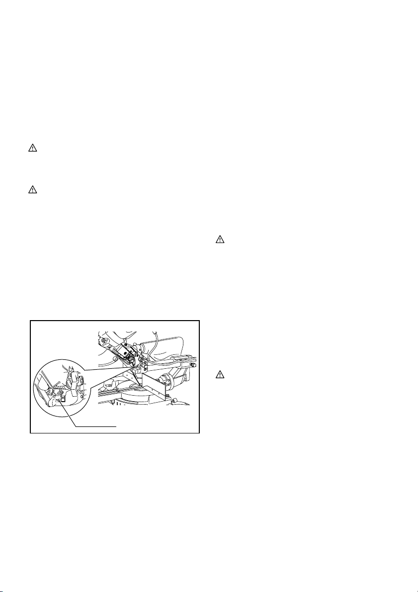
Elektronisk funktion
Mjukstartfunktion
• Denna funktion ger en mjuk uppstart av maskinen
genom att begränsa vridmomentet vid uppstarten.
Laserstrålens funktion
Endast för modell LS1018L
OBS!
• Montera två AA-torrbatterier i batterihållaren före
första användningen. För montering, se avsnittet
med rubriken “Utbyte av torrbatterierna i
laserenheten”.
FÖRSIKTIGT!
• Var noga med att stänga av lasern när den inte
används
Fig.18
FÖRSIKTIGT!
• Titta aldrig in i laserstrålen. Direkt laserljus kan
skada ögonen.
• LASERSTRÅLNING, TITTA INTE DIREKT I
LASERSTRÅLEN, LASERPRODUKT KLASS 2.
• Se till att koppla bort maskinen från elnätet innan
laserlinjen ändras eller när underhåll eller justering
utförs.
Sätt på lasern genom att trycka upptill (I) på brytaren.
Tryck nertill (0) på brytaren för att stänga av lasern.
Laserlinjen kan flyttas antingen till vänster eller höger
om sågklingan genom att lossa skruven som fäster
laserenhetens låda och placera den i önskad riktning. Se
till att dra åt skruven efter omplaceringen.
1
1. Skruv som fäster laserenhetens låda
010473
Laserlinsen är fabriksinställd så att den ligger inom 1
mm från sågklingans sida (sågposition).
OBS!
• När laserlinjen verkar oklar och är svår att se på
grund av direkt solljus ska du byta till en mer
skuggig arbetsplats.
Utbyte av torrbatterierna i laserenheten
Fig.19
Fig.20
Ta bort locket för torrbatterierna i laserenheten genom
att skjuta på locket samtidigt som du trycker på det. Ta
bort de gamla torrbatterierna och sätt i de nya såsom
visas i figuren. Sätt tillbaka locket för att täcka dem när
det är klart.
Rengöring av laserns lins
Om laserns lins blir smutsig eller om sågspån fastnar på
den så att inte laserlinjen syns stänger du av maskinen,
tar bort linsen och rengör den försiktigt med en fuktig
mjuk trasa. Använd inte lösningsmedel eller
petroleumbaserade rengöringsmedel på linsen.
OBS!
• När laserlinjen är suddig och nästan helt osynlig på
grund av direkt solbelysning, inne eller ute, flyttar
du arbetsplatsen till en plats som inte är solbelyst.
MONTERING
VAR NING!
• Se alltid till att maskinen är avstängd och att
nätsladden är urdragen innan du utför arbete
på maskinen. I annat fall kan det leda till allvarlig
personskada.
Förvaring av hylsnyckel med insexnyckel på
dess andra ände
Fig.21
Hylsnyckeln förvaras på det sätt som framgår av bilden.
När hylsnyckeln behöver användas kan den dras ut ur
dess hållare. Efter användningen kan du förvara den i
dess hållare igen.
Montering eller borttagning av sågblad
VAR NING!
• Se alltid till att maskinen är avstängd och
nätsladden urdragen innan du monterar eller
tar bort sågklingan. Oavsiktlig start av maskinen
kan leda till allvarlig personskada.
• Använd endast medföljande hylsnyckel från
Makita för att montera eller ta bort klingan.I
annat fall kan det leda till att insexbultarna dras åt
för mycket eller för lite vilket kan resultera i allvarlig
personskada.
Fig.22
Lås handtaget i det upphöjda läget genom att trycka in
låstappen.
Fig.23
När du ska ta ur klingan använder du hylsnyckeln för att
lossa på insexbulten som håller fast mitthöljet, genom att
vrida den moturs. Lyft på klingskyddet och mitthöljet.
27
Page 28

Fig.24
Tryck på spindellåset för att låsa spindeln och använd
hylsnyckeln för att lossa på insexbulten genom att vrida
den medurs. Ta sedan bort insexbulten, den yttre
flänsen och klingan.
OBS!
• Om den inre flänsen är borttagen måste du se till
att montera den på spindeln med dess utskjutande
del bort från klingan. Om flänsen inte monteras
korrekt kommer den att skava mot maskinen.
VAR NING!
• Innan klingan monteras på spindeln ska du
alltid se till att korrekt insatsring för axelhålet
på den klinga du ska använda monteras mellan
den inre och den yttre flänsen. Att använda fel
insatsring för axelhålet kan leda till felaktig
montering av klingan vilket orsakar förflyttning av
den och ger allvarliga vibrationer. Detta kan leda till
att du förlorar kontrollen under användningen och
orsaka allvarlig skada.
Fig.25
För att montera klingan sätter du den försiktigt på
spindeln, och ser till att riktningen på den pil som finns
på klingans sida stämmer överens med pilens riktning
på klinghöljet.
Montera den yttre flänsen och insexbulten, och använd
sedan hylsnyckeln för att dra åt insexbulten
(vänstergängad, dras moturs) ordentligt medan du håller
in spindellåset.
För alla länder utanför Europa
Fig.26
VAR NING!
• Den svarta ringen med en ytterdiameter på 25 mm
och silverringen med en ytterdiameter på 25,4 mm
är fabriksmonterade, såsom visas i figuren. När du
använder en klinga med en håldiameter på 25 mm,
ska du byta ut silverringen mot den svarta ringen.
Innan klingan monteras på spindeln ska du
alltid se till att korrekt insatsring för axelhålet
på den klinga du ska använda, monteras
mellan den inre och den yttre flänsen. Att
använda fel insatsring för axelhålet kan leda till
felaktig montering av klingan vilket orsakar
förflyttning av den och ger allvarliga vibrationer.
Detta kan leda till att du förlorar kontrollen under
användningen och orsaka allvarlig skada.
För länder i Europa
FÖRSIKTIGT!
• Insatsringen med en yttre diameter på 30 mm har
fabriksmonterats mellan den inre och yttre flänsen.
Montera den yttre flänsen och insexbulten, och använd
sedan hylsnyckeln för att dra åt insexbulten (moturs)
ordentligt medan du håller in spindellåset.
Fig.27
För tillbaka klingskyddet och mitthöljet till dess
ursprungliga läge. Dra sedan åt insexbulten medurs för
att fästa mitthöljet. Släpp handtaget från upplyft läge
genom att dra ut låstappen. Sänk ner handtaget för att
försäkra dig om att klingskyddet fungerar som det ska.
Kontrollera att spindellåset inte längre låser fast spindeln
innan du börjar såga.
Dammpåse (tillbehör)
Fig.28
Användning av dammpåsen ger ett renare sågarbete
och förenklar uppsamlingen av damm. Anslut
dammpåsen på munstycket för dammutkastet.
Ta bort dammpåsen från maskinen när den är cirka
halvfull och dra ut plastlåset. Töm dammpåsen på dess
innehåll och slå lätt på den för att avlägsna partiklar som
fastnat på insidan, vilket annars kan hindra fortsatt
uppsamling.
OBS!
Du kan få renare under arbetet om du ansluter en
dammsugare till sågen.
Fastsättning av arbetsstycke
VAR NING!
•
Det är ytterst viktigt att alltid fästa
arbetsstycket korrekt med rätt typ av tving
eller kronliststopp.
I annat fall kan det leda till
allvarlig personskada och orsaka skada på
maskinen och/eller arbetsstycket.
• Lyft aldrig klingan förrän den har stannat helt
efter sågningen. I annat fall kan det leda till
allvarlig personskada och skada på arbetsstycket.
• När du sågar ett arbetsstycke som är längre än
sågens stödyta ska hela arbetsstycket stödjas,
även den del som befinner sig utanför sågens
stödyta, samt på samma höjd för att vara i nivå.
Detta för att undvika att klingan nyper fast och ett
eventuellt bakåtkast vilket kan leda till allvarlig
personskada. Lita inte enbart på den vertikala
och/eller horisontala tvingen för att fästa
arbetsstycket. Tunt material tenderar att svikta.
Stötta hela arbetsstyckets längd för att undvika att
klingan nyper fast och eventuellt orsakar
BAKÅTKAST.
Fig.29
Justering av anhåll (SKJUTBARA ANHÅLL
vilka är de övre och nedre anhållen)
Fig.30
VAR NING!
• Kontrollera att det skjutbara anhållet är ordentligt
fäst innan du använder maskinen.
• Se till före vinkelsågningen att ingen del av
maskinen, speciellt klingan, kommer i kontakt
med de övre och de nedre anhållen när
28
Page 29

maskinhandtaget sänks ner eller höjs upp helt,
eller när vagnen skjuts framåt eller dras bakåt
hela vägen. I annat fall kan det leda till bakåtkast
eller att arbetsstycket oväntat rör sig och orsakar
allvarlig personskada.
Fig.31
FÖRSIKTIGT!
• För det skjutbara anhållet till vänster och fäst det
såsom visas i figuren vid vinkelsågning. I annat fall
kommer det i kontakt med klingan eller en del av
maskinen, vilket kan leda till allvarliga skador på
användaren.
Maskinen är utrustad med det skjutbara anhållet vilket
vanligen ska placeras såsom visas i figuren.
Vid vänsterställd vinkelsågning ska det dock ställas in i
det vänstra läget, såsom visas i figuren, om
maskinhuvudet kommer i kontakt med det.
Glöm inte att flytta tillbaka det skjutbara anhållet till dess
ursprungliga läge och fäst det genom att dra åt
låsskruven hårt när vinkelsågningen är klar.
Stödanhåll R
VAR NING!
• Kontrollera att stödanhållet R är ordentligt fäst
innan du använder maskinen.
• Ta bort stödanhållet R innan högerställd
vinkelsågning utförs. Stödanhållet kommer att
komma i kontakt med klingan eller någon del av
maskinen, vilket kan leda till allvarliga skador på
användaren.
Fig.32
Stödanhållet R kan tas bort från anhållets högra sida.
För att ta bort det lossar du skruven som fäster det och
dra ut stödanhållet R. Följ denna procedur i omvänd
ordning för att montera det.
Glöm inte att sätta tillbaka stödanhållet R i dess
ursprungliga läge och fäst det genom att dra åt
låsskruven ordentligt när vinkelsågningen är klar.
Vertikal tving
Fig.33
Den vertikala tvingen kan monteras antingen på vänster
eller höger sida om anhållet. Sätt i tvingens fäststav i
hålet på anhållet och dra åt skruven på anhållets
baksida för att fästa tvingens fäststav.
Sätt tvingarmen i läge så att den passar till
arbetsstyckets tjocklek och form och fäst den sedan
genom att dra åt skruven. Om skruven som fäster
tvingarmen kommer i kontakt med anhållet måste den
flyttas till tvingarmens andra sida. Se till att ingen del av
maskinen kommer i kontakt med tvingen när
maskinhandtaget sänks till sin lägsta position eller när
vagnen skjuts framåt eller dras bakåt hela vägen. Om
någon del kommer i kontakt med tvingen monterar du
om den.
Tryck arbetsstycket plant mot anhållet och geringsskivan.
Placera arbetsstycket i önskat sågläge och fäst det
stadigt genom att dra åt tvingens ratt.
VAR NING!
• Arbetsstycket måste fästas säkert mot
geringsskivan och anhållet med tvingen under
all drift. Om arbetsstycket inte är korrekt fastsatt
mot anhållet kan arbetsstycket röra sig under
sågarbetet och orsaka möjlig skada på klingan och
att arbetsstycket kastas iväg samt att du förlorar
kontroll över maskinen vilket leder till allvarlig
personskada.
Horisontal skruvtving (valfritt tillbehör)
Fig.34
Den horisontala tvingen kan monteras i två lägen,
antingen på vänster eller höger sida av sågbordet. Vid
geringssågning i 10° eller mer, skall den horisontala
tvingen monteras på motsatta sidan till den riktning i
vilket geringsskivan skall vridas.
Fig.35
Genom att vrida tvingmuttern moturs frigörs tvingen och
kan snabbt flyttas inåt och utåt. För att fästa ett
arbetsstycke trycker du tvingens ratt framåt tills tvingens
platta kommer i kontakt med arbetsstycket och vrider
sedan tvingmuttern medurs. Fästa sedan arbetsstycket
genom att vrida tvingens ratt medurs.
Den maximala bredden på arbetsstycke som kan fästas
med den horisontala tvingen är 215 mm.
Vid montering av den horisontala tvingen på sågbordets
högra sida, skall stödanhållet R också användas för att
fästa arbetsstycket mer ordentligt. Se avsnittet
"Stödanhåll R" som tidigare beskrivits för montering av
stödanhåll R.
VAR NING!
• Rotera alltid tvingmuttern medurs tills
arbetsstycket är ordentligt fäst. I annat fall kan
arbetsstycket röra sig under sågarbetet och orsaka
möjlig skada på klingan och att arbetsstycket
kastas iväg samt att du tappar kontrollen över
maskinen, vilket kan leda till allvarlig personskada.
•
Använd alltid den horisontala tvingen när du sågar
ett tunt arbetsstycke, såsom golvlister, mot
anhållet.
Hållare
Fig.36
Hållarna kan monteras på endera sidan för att på ett
praktiskt och bekvämt sätt hålla arbetsstyckena
horisontellt. Skjut in hållarens fäststavar helt i hålen i
sågbordet. Fäst sedan hållarna ordentligt med
skruvarna.
VAR NING!
•
Stöd alltid ett långt arbetsstycke så att det är
på samma nivå som geringsskivans ovansida
för att få ett exakt sågresultat och för att
förhindra att du förlorar kontrollen över
29
Page 30
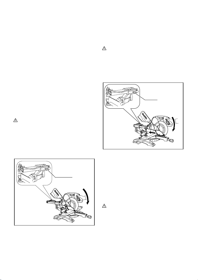
maskinen.
Med korrekt stöd av arbetsstycket
undviker du att klingan nyper fast och eventuellt
orsakar ett BAKÅTKAST vilket kan resultera i
allvarlig personskada.
ANVÄNDNING
OBS:
• Se till att lösgöra handtaget från dess nedsänkta
läge genom att dra ut låstappen.
• Tryck inte för mycket på handtaget vid sågningen.
Detta kan leda till att motorn överbelastas och/eller
försämrad sågning. Tryck ner handtaget endast så
mycket som behövs för att sågningen ska löpa
smidigt utan att klingans hastighet minskar
påtagligt.
• Tryck försiktigt ner handtaget för att såga. Om
handtaget trycks ner hårt eller i sidled kommer
klingan att vibrera vilket ger sågmärken i
arbetsstycket samtidigt som sågprecisionen
försämras.
• Vid skjutsågning skall vagnen försiktigt tryckas mot
anhållet utan att stoppa. Om vagnens rörelser
upphör under sågningen lämnas ett märke på
arbetsstycket och precisionen i snittet minskar.
VAR NING!
• Kontrollera att inte klingan är i kontakt med
arbetsstycket eller något annat innan sågen
sätts på.
I annat fall kan det leda till bakåtkast och allvarlig
personskada.
1. Sågning genom tryck (sågning av små
arbetsstycken)
1
1. Låsskruv
011409
Arbetsstycken som är upp till 91 mm höga och 70
mm breda kan sågas på följande sätt.
Tryck vagnen fullständigt mot anhållet och dra åt
låsskruven medurs för att fästa vagnen. Fäst
arbetsstycket rätt med passande sorts tving. Starta
maskinen utan att klingan har kontakt med
arbetsstycket och vänta tills klingan har uppnått full
hastighet innan du sänker ner den. Sänk sedan
handtaget försiktigt tills det har sänkts helt, för att
såga arbetsstycket. Stäng av maskinen när
sågningen är avslutad och VÄNTA TILLS
KLINGAN HAR STANNAT FULLSTÄNDIGT, innan
klingan återförs till sitt helt uppfällda läge.
VAR NING!
• Dra åt ratten ordentligt medurs så att vagnen
inte rör sig under användningen. I annat fall kan
det leda till bakåtkast vilket kan orsaka allvarlig
personskada som följd.
2. Sågning genom skjutning (sågning av breda
arbetsstycken)
1
1. Låsskruv
011410
Lossa låsskruven moturs så att vagnen kan skjutas
fritt. Fäst arbetsstycket med rätt sorts tving. Dra
vagnen mot dig helt och hållet. Starta maskinen
utan att klingan vidrör arbetsstycket och vänta tills
klingan uppnår full hastighet. Tryck ner handtaget
och SKJUT VAGNEN MOT ANHÅLLET FÖR ATT
SÅGA IGENOM ARBETSSTYCKET. Stäng av
maskinen när sågningen är avslutad och VÄNTA
TILLS KLINGAN HAR STANNAT FULLSTÄNDIGT
innan klingan återförs till sitt helt uppfällda läge.
VAR NING!
• Vid skjutsågning ska du först dra vagnen
fullständigt mot dig och trycka ner handtaget
till dess helt nedsänkta läge. Skjut sedan
vagnen mot anhållet. Börja aldrig sågningen
om vagnen inte är dragen fullständigt mot dig.
Om skjutsågning utförs utan att du dragit vagnen
helt mot dig kan ett bakåtkast uppstå med risk för
allvarlig personskada.
• Försök aldrig att utföra en skjutsågning genom
att dra vagnen mot dig. Att dra vagnen mot dig
medan du sågar kan orsaka bakåtkast vilket
resulterar i möjlig personskada.
30
Page 31

• Utför aldrig skjutsågning med handtaget låst i det
nedsänkta läget.
• Lossa aldrig på låsskruven som fäster vagnen
medan klingan roterar. Om vagnen är lös medan
du sågar kan det orsaka ett bakåtkast vilket kan
resultera i allvarlig personskada.
3. Geringssågning
Se avsnittet "Inställning av geringsvinkeln" som
förklarats tidigare.
4. Vinkelsågning
Fig.37
Lossa spaken och luta sågklingan till den önskade
vinkeln (se avsnittet "Inställning av vinkeln för
vinkelsågning" som beskrivits tidigare). Se till att
spaken dras åt ordentligt för att fästa sågen säkert i
den valda vinkeln. Fäst arbetsstycket med en tving.
Kontrollera att vagnen har dragits tillbaka så långt
det går mot användaren. Starta maskinen utan att
klingan vidrör arbetsstycket och vänta tills klingan
uppnår full hastighet. Sänk sedan handtaget
försiktigt till dess helt nedsänkta läge medan tryck
parallellt med klingan anläggs och SKJUT
VAGNEN MOT ANHÅLLET FÖR ATT SÅGA
ARBETSSTYCKET. Stäng av maskinen när
sågningen är avslutad och VÄNTA TILLS
KLINGAN HAR STANNAT FULLSTÄNDIGT innan
klingan återförs till sitt helt uppfällda läge.
VAR NING!
• Efter inställning av klingan för vinkelsågning
och innan du börjar arbeta med maskinen, ska
du se till att vagnen och klingan har fri väg
genom hela skäret. Vagns- eller klingavbrott
under sågningen kan orsaka bakåtkast och
allvarlig personskada.
• Håll händerna borta från klingans såglinje när
du utför en vinkelsågning. Klingans vinkel och
den verkliga såglinjen kan förvirra användaren
under sågningen och kontakt med klingan orsakar
allvarlig personskada.
•
Klingan ska aldrig lyftas förrän den har stannat
helt.
Under vinkelsågning kan det avsågade
stycket ligga kvar mot klingan. Om klingan lyfts
upp medan den roterar kan det avsågade stycket
kastas ut av klingan och orsaka att material
fragmenteras vilket kan resultera i allvarlig
personskada.
OBS:
• När du trycker ner handtaget ska du trycka i
samma riktning som klingan lutar. Om tryck
anläggs vinkelrätt mot geringsskivan eller om
tryckets riktning ändras under pågående sågning,
minskar sågprecisionen.
• Innan du utför vinkelsågning kanske du behöver
justera det övre och det undre anhållet. Se
avsnittet med rubriken ”Justering av anhåll”.
FÖRSIKTIGT!
• Skjut eller ta alltid bort stödanhållet R så att det
inte hindrar någon del av vagnen när vinkelsågning
utförs.
5. Kombinationssågning
Kombinationssågning är en process där
vinkelsågning utförs i kombination med att en
geringsvinkel sågas i ett arbetsstycke.
Kombinationssågning kan utföras vid vinkel som
visas i tabellen nedan.
Geringsvinkel Vinkel för vinkelsågning
009713
Vänster och höger 0 - 45Vänster och höger 0 - 45
Se avsnittet "Sågning genom tryck", "Sågning
genom skjutning", "Geringssågning" och
"Vinkelsågning" när du vill utföra
kombinationssågning.
6. Sågning av kron- och hållister
Kron- och hållister kan sågas på en kap- och
geringskombinationssåg med listerna placerade
plant på geringsskivan.
Det finns två vanliga sorter av kronlister och en
sort av hållist; 52/38° väggvinklad kronlist, 45°
väggvinklad kronlist och 45° väggvinklad hållist. Se
illustrationer.
Fig.38
Det finns kron- och hållistskarvar som är gjorda för
att passa på "insidan" av 90° hörn ((1) och (2) i fig.
A) och "utsidan" av 90° hörn ((3) och (4) i fig. A).
1. Insidan av hörn
2. Utsidan av hörn
(1) (2) (3)(4)
Fig. A
001556
1 2
Fig.39
Mätning
Mät vägglängden och justera arbetsstycket på
bordet för att såga väggkontaktytan till önskad
längd. Kontrollera alltid att längden för det sågade
arbetsstycket på arbetsstyckets baksida är
densamma som vägglängden. Justera såglängden
för sågvinkeln. Använd alltid flera bitar för
testsågning för att kontrollera sågvinkeln.
Vid sågning av kron- och hållister ska vinkeln för
vinkelsågning och geringsvinkeln ställas in såsom
anges i tabell (A) och listerna placeras på
sågbordet såsom visas i tabell (B).
31
Page 32

Vid vänsterställd vinkelsågning
Tabell (A)
Vinkel för vinkelsågning
52/38° sort 45° sort
(1)
(2)
Vänster 33,9°
(3)
(4)
Vänster 30°
För insidan
av hörn
För utsidan
av hörn
006361
Listens läge
i fig. A
Tabell (B)
Listens läge
Listkanten mot anslaget
i fig. A
Takkanten ska ligga an mot
(1)
För insidan
av hörn
För utsidan
av hörn
006362
anslaget.
(2)
Väggkontaktytan ska ligga
an mot anslaget.
(3)
Takkanten ska ligga an mot
(4)
anslaget.
Exempel:
Vid sågning av kronlist med 52/38° för
position (1) i fig. A:
• luta och fäst vinkeln vid 33,9° LEFT
(VÄNSTER).
• Justera och fäst geringsvinkeln vid
31,6° RIGHT (HÖGER).
• lägg kronlisten med dess breda baksida
(dold) ner mot geringsskivan och med
TAKKANTEN mot anhållet på sågen.
• Den färdiga biten som ska användas är
alltid på VÄNSTER sida om klingan
efter det att sågningen är avslutad.
Vid högerställd vinkelsågning
Tabell (A)
Vinkel för vinkelsågning
52/38° sort 45° sort
(1)
(2)
Höger 33,9° Höger 30°
(3)
(4)
För insidan
av hörn
För utsidan
av hörn
006363
Listens läge
i fig. A
Tabell (B)
Listens läge
Listkanten mot anslaget
i fig. A
Väggkontaktytan ska ligga
(1)
För insidan
av hörn
För utsidan
av hörn
006364
an mot anslaget.
(2)
Takkanten ska ligga an mot
anslaget.
(3)
Väggkontaktytan ska ligga
(4)
an mot anslaget.
Geringsvinkel
52/38° sort
Höger 31,6°
Vänster 31,6° Vänster 35,3°
52/38° sort
Höger 31,6°
Vänster 31,6° Vänster 35,3°
45° sort
Höger 35,3°
Höger 35,3°Höger 31,6°
Färdigt arbetsstycke
Det färdiga arbetsstycket
hamnar på klingans
vänstra sida.
Det färdiga arbetsstycket
hamnar på klingans
högra sida.
Geringsvinkel
45° sort
Höger 35,3°
Höger 35,3°Höger 31,6°
Färdigt arbetsstycke
Det färdiga arbetsstycket
hamnar på klingans
högra sida.
Det färdiga arbetsstycket
hamnar på klingans
vänstra sida.
Exempel:
Vid sågning av kronlist med 52/38° för
position (1) i fig. A:
• luta och fäst vinkeln vid 33,9° RIGHT
(HÖGER).
• Justera och fäst geringsvinkeln vid
31,6° RIGHT (HÖGER).
• lägg kronlisten med dess breda baksida
(dold) ner på geringsskivan med
VÄGGKONTAKTYTAN mot anslaget på
sågen.
• Den färdiga biten som ska användas är
alltid på HÖGER sida om klingan efter
det att sågningen är avslutad.
7. Sågning av aluminiumstycken
Fig.40
Fig.41
Använd klossar eller träbitar när ett
aluminiumstycke skall fästas såsom visas i figuren,
för att förhindra att aluminiumstycket deformeras.
Använd sågolja vid sågningen i aluminium, för att
förhindra att aluminiummaterialet fastnar och
lagras på klingan.
VAR NING!
• Försök aldrig såga tjocka eller runda
aluminiumstycken. Tjocka eller runda
aluminiumstycken kan vara svåra att fästa och kan
lossa under arbetet vilket kan leda till att du tappar
kontrollen över maskinen och allvarlig skada
uppstår.
8. Träskoning
Skoning med trä hjälper att ge stickfri sågning av
arbetsstycken. Sätt fast en skoning på anhållet
med hjälp av hålen i anhållet.
I figuren visas dimensionerna på föreslagen
träskoning.
15mm Över 500 mm
20 mm
80mm-90mm
1
24 mm
1. Hål
010563
1
68mm 121mm
121mm
68mm
FÖRSIKTIGT!
• Använd ett rakt trästycke av jämn tjocklek som
skoning.
VAR NING!
•
Använd skruvar för att fästa träskoningen till
anhållet. Skruvarna ska fästas så att
skruvhuvudena är placerade lägre än
träskoningens yta, så att de inte påverkar läget
32
Page 33

för det material som ska sågas.
Felaktig
inriktning av materialet som ska sågas kan orsaka
oväntad rörelse under sågarbetet vilket kan leda
till att du förlorar kontrollen och orsaka allvarlig
personskada.
OBS:
• Vrid inte på geringsskivan när träskoningen sitter
på och handtaget är nedsänkt. Detta skadar
klingan och/eller träskoningen.
9. Spårsågning
Fig.42
Spårsågning kan utföras genom att göra på
följande sätt:
Justera klingans lägsta position genom att vrida på
inställningsskruven och stopparmen för att ställa in
klingans sågdjup. Se avsnittet "Stopparm" som
beskrivits tidigare.
Såga parallella spår tvärs över arbetsstyckets hela
bredd genom skjutsågning (trycksågning), såsom
visas i figuren, efter att klingans nedre gränsläge
justerats. Avlägsna sedan materialet mellan
spåren på arbetsstycket med ett stämjärn.
VAR NING!
• Försök inte utföra denna typ av sågning genom
att använda en bredare (tjockare) klinga eller
en dadoklinga. I annat fall kan det leda till
oväntade sågresultat och möjligt bakåtkast vilket
kan resultera i allvarlig personskada.
• Se noga till att stopparmen återförs till det
ursprungliga läget vid annan sågning än
spårsågning. Att försöka såga med stopparmen i
fel läge kan leda till oväntade sågresultat och
bakåtkast vilket kan resultera i allvarlig
personskada.
FÖRSIKTIGT!
• Se noga till att stopparmen återförs till det
ursprungliga läget vid annan sågning än
spårsågning.
Bära maskinen
Fig.43
Se till att maskinens nätsladd är urdragen. Fäst klingan
vid 0° vinkel för vinkelsågning och vrid geringsskivan
helt mot höger geringsvinkel. Fäst skjutstängerna så att
den nedre skjutstången är låst i vagnsläget och helt
dragen mot användaren, och de övre skjutstängerna är
låsta i vagnsläget och helt tryckta framåt mot anslaget
(se avsnittet med rubriken "Inställning av skjutlås".)
Sänk ner handtaget helt och lås det i nedsänkt läge
genom att trycka in låstappen.
Linda upp strömkabeln med kabelhållaren.
VAR NING!
• Låstappen används endast när maskinen ska
transporteras och förvaras. Aldrig under
sågarbeten. Att använda låstappen vid
sågarbeten kan leda till oavsiktlig rörelse av
sågklingan vilket orsakar bakåtkast och allvarlig
personskada.
Bär maskinen genom att hålla i båda sidorna av
sågbordet, såsom visas i figuren. Om hållare,
dammpåse etc. tas bort går det lättare att bära
maskinen.
FÖRSIKTIGT!
• Fäst alltid alla rörliga delar innan du bär maskinen.
Om delar av maskinen rör sig eller glider medan du
bär den kan du förlora kontrollen eller balansen
över maskinen vilket kan leda till personskada.
UNDERHÅLL
VAR NING!
•
Se alltid till att maskinen är avstängd och
nätsladden urdragen innan du inspekterar
eller utför underhåll på den.
leda till möjlig allvarlig personskada vid en
oavsiktlig start.
• Se alltid till att klingan är vass och ren för att få
ett så bra och säkert resultat som möjligt. Att
försöka såga med en slö och/eller smutsig klinga
kan orsaka bakåtkast och resultera i allvarlig
personskada.
OBS:
•
Använd inte bensin, thinner, alkohol eller liknande.
Missfärgning, deformation eller sprickor kan
uppstå
Inställning av sågvinkeln
Maskinen är noga inställd och inriktad på fabriken, men
ovarsam hantering kan påverka detta. Om maskinen
inte är korrekt riktad gör du på följande sätt:
1. Geringsvinkel
Fig.44
Tryck vagnen mot anhållet och dra åt låsskruven
för att fästa vagnen.
Lossa handtaget som fäster geringsskivan. Vrid
geringsskivan så att pekaren indikerar 0° på
geringsskalan. Vrid sedan geringsskivan en aning
medurs och moturs för att sätta geringsskivan i
hacket för 0° geringsvinkel. (Lämna det som det är
om pekaren inte indikerar 0°.) Lossa insexbultarna
som fäster anhållet med hylsnyckeln.
Fig.45
Sänk ner handtaget helt och lås det i nedsänkt läge
genom att trycka in låstappen. Justera klingans
sida och anhållets framsida i rät vinkel med en
vinkelhake, vinkellinjal etc. Dra sedan åt
insexbultarna ordentligt som håller anhållet, i
ordningen med start från höger sida.
Fig.46
Kontrollera att pekaren indikerar 0° på
geringsskalan. Om pekaren inte pekar på 0° lossar
33
I annat fall kan det
Page 34

du skruven som fäster pekaren och justerar
pekaren så att den indikerar 0°.
2. Vinkel för vinkelsågning
(1) 0° vinkel för vinkelsågning
Fig.47
Tryck vagnen mot anhållet och dra åt
låsskruven för att fästa vagnen. Sänk ner
handtaget helt och lås det i nedsänkt läge
genom att trycka in låstappen. Lossa spaken
på maskinens baksida.
Fig.48
Vrid insexbulten på armens högra sida två
eller tre varv moturs, för att luta klingan åt
höger.
Fig.49
Justera noggrant klingans sida och
geringsskivans ovansida i rät vinkel med en
vinkelhake, vinkellinjal etc. genom att vrida
insexbulten på armens högra sida medurs.
Dra sedan åt spaken ordentligt.
Fig.50
Kontrollera att pekaren på armen indikerar 0°
på armhållarens vinkelskala. Om de inte
skulle peka på 0° lossar du skruven som
fäster pekaren och justerar den så att den
indikerar 0°.
(2) 45° vinkel för vinkelsågning
Fig.51
Justera vinkeln för 45° vinkelsågning först
efter att vinkeln för 0° vinkelsågning har
ställts in. Lossa spaken och luta klingan så
långt som det går till vänster, för att justera
vänster vinkel för 45° vinkelsågning.
Kontrollera att pekaren på armen indikerar
45° på armhållarens vinkelskala. Om
pekaren inte indikerar 45° vrider du den 45°
inställningsbulten för vinkel för vinkelsågning
på armhållarens högra sida tills pekaren
indikerar 45°.
För att justera den högra 45° vinkelsågningen,
utför samma procedur som beskrivits ovan.
Fig.52
Ta bort och kontrollera kolborstarna regelbundet. Byt
dem när de är nedslitna till 3 mm längd. Håll
kolborstarna rena så att de lätt kan glida in i hållarna.
Båda kolborstarna ska bytas ut samtidigt. Använd
endast identiska kolborstar.
Fig.53
Använd en skruvmejsel för att ta bort locken till
kolborstarna. Ta ur de utslitna kolborstarna, montera nya
och montera locken.
Efter användning
• Ta bort de spån och det damm som har fastnat på
maskinen med en tygduk eller liknande efter att
arbetet är avslutat. Se till att du håller klingskyddet
rent, i enlighet med de anvisningar som tidigare
beskrivits i avsnittet med titeln "Klingskydd". Smörj
in de rörliga delarna med maskinolja för att
förhindra rostbildning.
• Dra vagnen fullständigt mot dig när maskinen skall
ställas undan för förvaring.
För att upprätthålla produktens SÄKERHET och
TILLFÖRLITLIGHET bör allt underhålls- och
justeringsarbete utföras av ett auktoriserat Makita
servicecenter och med reservdelar från Makita.
VALFRIA TILLBEHÖR
VAR NING!
• Dessa tillbehör eller tillsatser från Makita
rekommenderas för användning med den
Makita-maskin som denna bruksanvisning
avser. Om andra tillbehör eller tillsatser används
kan det resultera i allvarlig personskada.
• Använd endast tillbehören eller tillsatserna från
Makita för de syfte de är avsedda för. I annat fall
kan det leda till allvarlig personskada.
Kontakta ditt lokala Makita servicecenter om du behöver
ytterligare information om dessa tillbehör.
• HM-pläterat sågblad av stål
Geringssågklingor
Kombination
Tvärsnitt
Fina tvärsnitt
Geringssågklingor för
andra metaller än järn
006526
Stödanhåll R
•
• Tvingsats (Horisontal tving)
• Vertikal tving
• Hylsnyckel med insexnyckel på dess andra ände
• Hållare
• Dammpåse
• Vinkelrör
• Vinkelhake
OBS!
• Några av tillbehören i listan kan vara inkluderade i
maskinpaketet som standardtillbehör. De kan
variera mellan olika länder.
För smidig och exakt sågning i olika material.
Klinga för allmänt bruk, för snabb och smidig klyvning,
kapning och geringssågning.
För smidigare tvärsnitt mot träets fibrerriktning.
Skär rent mot träets fiberriktning.
Sandfria, rena kapsnitt tvärs med fibrerna/ strukturen.
För gering i aluminium, koppar, mässing, rör och
andra metaller än järn.
34
Page 35

NORSK (originalinstruksjoner)
1-1. Anslagsstift
2-1. Skruer
3-1. Bladvern
4-1. Bladvern
5-1. Skrue
5-2. Snittplate
6-1. Sagblad
6-2. Bladtenner
6-3. Snittplate
6-4. Venstre skråkutt
6-5. Rett kutt
6-6. Høyre skråkutt
7-1. Justeringsskrue
7-2. Dreiefot
8-1. Toppoverflate på dreiefot
8-2. Utkanten av bladet
8-3. Føringsflate
9-1. Stopperarm
9-2. Justeringsskrue
10-1. Gjæringsskala
10-2. Pil
10-3. Låsehendel
10-4. Håndtak
11-1. Spak
12-1. Spak
12-2. Arm
12-3. Pil
12-4. Skråskala
13-1. Spak
14-1. Pil
14-2. Utløserknapp
14-3. Skråskala
15-1. Låseskrue
16-1. AV-sperreknapp
16-2. Startbryter
16-3. Spak
16-4. Hull for hengelås
17-1. AV-sperreknapp
17-2. Startbryter
17-3. Hull for hengelås
18-1. Bryter for laser
20-1. Tørrelement
21-1. Pipenøkkel med sekskantnøkkel i
andre enden
Oversiktsforklaring
21-2. Nøkkelholder
22-1. Anslagsstift
23-1. Pipenøkkel
23-2. Bladkasse
23-3. Midtdeksel
23-4. Sekskantskrue
23-5. Bladvern
24-1. Bladkasse
24-2. Pipenøkkel
24-3. Sekskantskrue
24-4. Pil
24-5. Spindellås
25-1. Bladkasse
25-2. Pil
25-3. Pil
25-4. Sagblad
26-1. Sekskantskrue (venstrehånds)
26-2. Ytre flens
26-3. Sagblad
26-4. Ring
26-5. Indre flens
26-6. Spindel
27-1. Pipenøkkel
27-2. Bladkasse
27-3. Midtdeksel
27-4. Sekskantskrue
27-5. Bladvern
28-1. Støvmunnstykke
28-2. Støvpose
28-3. Festemekanisme
29-1. Støtte
29-2. Dreiefot
30-1. Skyvevern
30-2. Klemskrue
31-1. Skyvevern
32-1. Tilleggsanlegg R
32-2. Skruer
33-1. Skrustikkearm
33-2. Skrustikkeknott
33-3. Skrustikkestang
33-4. Skrue
33-5. Føringsflate
34-1. Skrustikkeplate
34-2. Skrustikkemutter
34-3. Skrustikkeknott
36-1. Holder
38-1. 52/38 ゚ type profillist
38-2. 45 ゚ type profillist
38-3. 45 ゚ type hulkillist
39-1. Innvendig hjørne
39-2. Utvendig hjørne
40-1. Føringsflate
40-2. Skrustikke
40-3. Avstandskloss
40-4. Aluminiumsekstrudering
40-5. Avstandskloss
41-1. Aluminiumsekstrudering
41-2. Føringsflate
41-3. Avstandskloss
41-4. Horisontal skrustikke (valgfritt
tilbehør)
42-1. Skjær spor med bladet
44-1. Sekskantskrue
44-2. Føringsflate
44-3. Håndtak
45-1. Føringsflate
45-2. Trekantlinjal
46-1. Skrue
46-2. Pil
46-3. Gjæringsskala
47-1. Spak
47-2. Arm
48-1. 0 ゚ justeringsskrue
48-2. Justeringsskrue for venstre 45 ゚
skråvinkel
49-1. Trekantlinjal
49-2. Sagblad
49-3. Toppoverflate på dreiebord
50-1. Skrue
50-2. Pil
50-3. Skråskala
51-1. Justeringsskrue for høyre 45 ゚
skråvinkel
51-2. Justeringsskrue for venstre 45 ゚
skråvinkel
53-1. Skrutrekker
53-2. Børsteholderhette
35
Page 36

TEKNISKE DATA
Modell LS1018 / LS1018L
Bladdiameter 255 mm - 260 mm
Hulldiameter
For alle land utenfor Europa 25,4 mm
For land i Europa 30 mm
Maks. skjærekapasitet (H x B) med 260 mm i diameter
Gjæringsvinkel
0° 50 mm x 310 mm 91 mm x 310 mm 31 mm x 310 mm
45° 50 mm x 220 mm 91 mm x 220 mm 31 mm x 220 mm
60° (høyre) - 91 mm x 153 mm Ubelastet turtall (min-1) 4 300
Lasertype (kun LS1018FL) Rød laser 650 nm, 1 mW (laserklasse 2)
Mål (L x B x H) 825 mm x 536 mm x 633 mm
Nettovekt For alle land utenfor Europa………19,8 kg
For land i Europa………………………………………19,9 kg
Sikkerhetsklasse /II
• Som følge av vårt kontinuerlige forsknings- og utviklingsprogram kan de tekniske dataene endres uten ytterligere forvarsel.
• Tekniske data kan variere fra land til land.
• Vekt i henhold til EPTA-prosedyre 01/2003
45° (venstre) 0° 45° (høyre)
END222-1
Symboler
Nedenfor ser du symbolene som brukes for dette
utstyret. Forviss deg om at du forstår hva de betyr, før du
begynner å bruke maskinen.
・ Les bruksanvisningen.
・ DOBBEL ISOLERING
・ For å unngå skader som følge av
flygende flis, må du holde saghodet
nede etter at sagingen er avsluttet, helt
til bladet har stoppet helt.
・ Når du gjør et glidekutt, dra først
føreanlegget helt og trykk ned
håndtaket, og trykk så føreanlegget mot
veiledningsanlegget.
・ Ikke legg hender eller fingre nær
sagbladet.
・ Juster skyvevernene godt unna
sagbladet og sagbladvernet.
・ Still alltid UNDERGJÆRDE mot høyre
når du skjærer skrått mot høyre. Hvis
du ikke følger denne anbefalingen, kan
det resultere i alvorlige helseskader for
brukeren.
・ Ikke se inn i laserstrålen. Laserstråler
rettet mot øynene, kan gi øyeskader.
・ Bare for land i EU
Kast aldri elektroutstyr i
husholdningsavfallet!
Skjæringsvinkel
I henhold til EU-direktiv 2002/96/EF om
kasserte elektriske og elektroniske
produkter og direktivets iverksetting i
nasjonal rett, må elektroutstyr som ikke
lenger skal brukes, samles separat og
returneres til et miljøvennlig
gjenvinningsanlegg
ENE006-1
Beregnet bruk
Denne maskinen er laget for nøyaktig, rett- og
gjæringsskjæring i tre. Med riktig sagblad kan også
aluminium sages.
ENF002-1
Strømforsyning
Maskinen må bare kobles til en strømkilde med samme
spenning som vist på typeskiltet, og kan bare brukes
med enfase-vekselstrømforsyning. Det er dobbelt
verneisolert i samsvar med europeiske standarder, og
kan derfor også brukes i kontakter uten jordledning.
ENG905-1
Støy
Typisk A-vektet lydtrykknivå er bestemt i henhold til
EN61029:
Lydtrykknivå (LpA) : 97 dB(A)
Lydeffektnivå (L
Usikkerhet (K): 3 dB(A)
) : 103 dB(A)
WA
Bruk hørselvern
ENG900-1
Vibrasjon
Den totale vibrasjonsverdien (triaksial vektorsum)
bestemt i henhold til EN61029:
36
Page 37

Genererte vibrasjoner (a
Usikkerhet (K): 1,5 m/s
•
Den angitte verdien for de genererte vibrasjonene er
): 2,5 m/s2 eller mindre
h
2
ENG901-1
blitt målt i samsvar med standardtestmetoden og kan
brukes til å sammenlikne et verktøy med et annet.
• Den angitte verdien for de genererte vibrasjonene
kan også brukes til en foreløpig vurdering av
eksponeringen.
ADVARSEL:
• De genererte vibrasjonene ved faktisk bruk av
elektroverktøyet kan avvike fra den oppgitte
vibrasjonsverdien, avhengig av hvordan verktøyet
brukes.
•
Vær påpasselig med å finne sikkerhetstiltak som
beskytter operatøren, basert på en oppfatning av
risiko under faktiske bruksforhold (på bakgrunn av
alle sider ved brukssyklusen, som når verktøyet slås
av og når det går på tomgang, i tillegg til oppstarten).
ENG015-2
Kun for europeiske land
Lyd og vibrering
Typisk A-vektede lydtrykknivåer er
Lydtrykknivå: 97 dB (A)
Lydeffektnivå: 103 dB (A)
Usikkerhet: 3 dB(A)
Bruk hørselvern.
Typisk vektet kvadratisk middelverdi av akselerasjonen
er ikke mer enn 2,5 m/s
Usikkerhet (K):1,5m/s
2
.
2
Disse verdiene er fremkommet i samsvar med
EN61029.
ENH003-12
Gjelder bare land i Europa
EF-samsvarserklæring
Som ansvarlig produsent erklærer Makita
Corporation at følgende Makita-maskin(er):
Maskinbetegnelse:
Skyvbar gjæringssag for kombinasjonssaging
Modellnr./type: LS1018, LS1018L
er av serieproduksjon og
samsvarer med følgende europeiske direktiver:
2006/42/EC
og er produsert i samsvar med følgende standarder eller
standardiserte dokumenter:
EN61029
Den tekniske dokumentasjonen oppbevares hos vår
autoriserte representant i Europa, som er:
Makita International Europe Ltd.
Michigan Drive, Tongwell,
Milton Keynes, MK15 8JD, England
000230
6.11.2009
Tomoyasu Kato
Direktør
Makita Corporation
3-11-8, Sumiyoshi-cho,
Anjo, Aichi, JAPAN
GEA010-1
Generelle advarsler angående
sikkerhet for elektroverktøy
ADVARSEL Les alle sikkerhetsadvarslene og alle
instruksjonene. Hvis du ikke følger alle advarslene og
instruksjonene som er oppført nedenfor, kan det føre til
elektriske støt, brann og/eller alvorlige helseskader.
Oppbevar alle advarsler og instruksjoner
for senere bruk.
ENB034-6
YTTERLIGERE
SIKKERHETSREGLER FOR
MASKINEN
1. Bruk hørselsvern.
2. Hold hendene unna banen til sagbladet.
Unngå kontakt med coasting blader. Det kan
føre til alvorlig personskade.
3. Ikke bruk maskinen uten at vernet er på plass.
Kontroller at det nedre vernet er ordentlig
lukket før bruk. Ikke begynn å bruke sagen
hvis det nedre vernet ikke beveger seg fritt og
lukker seg momentant. Bladvernet må aldri
klemmes fast eller bindes opp i åpen stilling.
4. Utfør aldri en jobb på frihånd Arbeidsstykket må
festes skikkelig mot dreiefoten og
veiledningsgjerdet med skrustikken ved all bruk.
Bruk aldri hånden til å sikre arbeidsstykket.
5. Strekk deg aldri rundt sagbladet.
6. Slå av maskinen og vent til sagbladet stopper
før du flytter arbeidsstykket eller endrer
innstillinger.
7. Trekk ut kontakten til maskinen før du skifter
blad eller reparerer den.
8. Sikre alltid alle bevegelige deler før du løfter
maskinen.
9. Stoppernålen som låser skjærehodet ned er
kun til for løfting eller oppbevaring og ikke for
å skjære.
10. Ikke bruk verktøyet i nærheten av brennbare
væsker eller gasser. Den elektriske driften av
vertøyet kan forårsake brann og eksplosjon når
den utsettes for brennbare væsker eller gasser.
11. Undersøk bladet nøye for sprekker eller skade
før bruk.
Bytt ut sprukne eller skadde blader
øyeblikkelig.
12. Bruk bare flenser som er spesifisert for denne
maskinen.
37
Page 38

13. Pass på å ikke skade akselen, flensene
(spesielt installeringsoverflaten) eller bolten.
Skade på disse delene kan resultere i at bladet
brekker.
14. Forsikre deg om at dreiefoten er sikret
skikkelig slik at den ikke kan forskyve seg
under bruk.
15. For din sikkerhet, fjern biter, små stykker, osv.
fra bordet før bruk.
16. Unngå å skjære i spiker. Se etter og fjern all
spiker fra arbeidsstykket før arbeidet
påbegynnes.
17. Forsikre deg om at skaftlåsen er av før du slår
på knappen.
18. Forsikre deg om at bladet ikke er i kontakt med
dreiefoten i den laveste stillingen.
19. Hold håndtaket godt fast. Vær oppmerksom på
at sagen går litt opp og ned når den startes og
stoppes.
20. Forviss deg om at bladet ikke er i kontakt med
arbeidsstykket før du slå på startbryteren.
21. Før du begynner å bruke maskinen på et
arbeidsstykke, bør du la den gå en liten stund.
Se etter vibrasjoner eller vingling som kan
tyde på at bladet er dårlig balansert.
22. Vent til bladet har full hastighet før du skjærer.
23. Hvis du merker at noe er uvanlig, må du
omgående stoppe arbeidet.
24. Ikke forsøk å låse avløseren i på-stillingen.
25. Vær alltid oppmerksom, spesielt under arbeid
som er rutinemessig og monotont. Ikke la deg
lure av en falsk sikkerhetsfølelse. Blader er
ekstremt uforsonlige.
26. Bruk alltid blader anbefalt i denne håndboken.
Bruk av upassende utstyr som rue hjul kan
føre til personskade.
27. Ikke bruk sagen til å skjære annet enn tre,
aluminium eller lignende materialer.
28. Koble gjæringssagene til et
støvoppsamlingsapparat når du sager.
29. Velg sagblad i forhold til materialet som skal
skjæres.
30. Vær forsiktig med kløyving.
31. Bytt ut snittbrettet når det er slitt.
32. Ikke bruk sagblader som er laget av
høyhastighetsstål.
33. Noen typer støv som produseres ved bruk
inneholder kjemikalier som er kjent for å
forårsake kreft, fosterskader eller annen
reproduktiv skade. Noen eksempler på disse
kjemikaliene er:
• bly fra materialer malt med blybasert
maling og,
• arsenikk og krom fra kjemisk behandlet
tømmer.
Risikoen du utsetter deg for, varierer etter
hvor ofte du gjør denne typen arbeid. For
å redusere utsettelsen for disse
TA VARE PÅ DISSE
INSTRUKSENE.
MONTERING
Montere benk
Fig.1
Når maskinen sendes fra fabrikken, er håndtaket låst i
senket stilling av stopperstiften. Slipp opp stopperstiften
ved å presse håndtaket forsiktig nedover mens du
trekker i stopperstiften.
Fig.2
Denne sagen bør boltes med fire skruer til en jevn og
stabil overflate ved hjelp av skruehullene i sagfoten.
Dette vil hjelpe deg å unngå velt og personskader.
FUNKSJONSBESKRIVELSE
Bladvern
Fig.3
Når du trekker ned håndtaket, vil bladvernet automatisk
bli hevet. Bladvernet går tilbake til opprinnelig stilling når
38
kjemikaliene: arbeid i et godt ventilert
område og bruk godkjent sikkerhetsutstyr,
som de støvmaskene som er utarbeidet
spesielt for å filtrere ut mikroskopiske
partikler.
34. Pass alltid på at bladet er skarpt og rent for å
redusere lydutslipp.
35. Den som skal bruke redskapet har fått god nok
opplæring i bruk, justering og drift av
maskinen.
36. Bruk riktig kvessede sagblader. Hold deg til
maksimum hastighet som merket på
sagbladet.
37. Ikke fjern avskjær eller andre deler av
arbeidsstykket fra skjæreområdet mens
maskinen er på og saghodet ikke er i
hvileposisjon.
38. Bruk bare sagblader som er anbefalt av
produsenten, som følger EN847-1.
39. Bruk hansker når du håndterer sagbladet
(sagbladene må bæres i en holder såfremt
dette er praktisk) og skarpe materialer.
40. Når laser er montert, er det ikke tillatt å bytte
ut denne med en annen type laser.
Reparasjoner må bare utføres korrekt.
ADVARSEL:
• Pass alltid på at maskinen er slått av og koblet
fra strømnettet (støpselet skal være ute av
stikkontakten) før du justerer eller sjekker
maskinens funksjon. Hvis maskinen ikke er
avslått og koblet fra strømnettet, kan den utilsiktet
bli startet opp og forårsake alvorlige personskader.
Page 39

kuttingen er fullført og håndtaket heves.
ADVARSEL:
• Bladvernet eller fjæren som er festet til vernet
skal aldri fjernes eller settes ute av funksjon.
Hvis vernet er satt ute av funksjon slik at et blad er
utildekt, kan det oppstå alvorlige personskader når
sagen er i bruk.
Av hensyn til din egen sikkerhet, må du alltid sørge for at
bladvernet er i god stand. Enhver uregelmessighet i
bladvernet må rettes opp omgående. Kontroller at vernet
er fjærbelastet, slik at det returnerer til opprinnelig stilling
når sagingen er ferdig.
ADVARSEL:
• Aldri bruk maskinen hvis bladvernet eller
fjæren er skadet, fungerer dårlig eller er fjernet.
Hvis maskinen brukes når vernet er skadet,
fungerer dårlig eller er fjernet, kan det oppstå
alvorlige personskader.
Hvis det gjennomsiktige bladvernet blir skittent, eller det
setter seg så mye sagflis på det at bladet og/eller
arbeidsstykket ikke lenger er godt synlig, må du koble
sagen fra strømnettet (støpselet skal være ute av
stikkontakten) og forsiktig tørke av vernet med en fuktig
klut. Ikke bruk løsemidler eller bensinbaserte
rengjøringsmidler på plastvernet, da dette kan skade
vernet.
Hvis bladvernet blir skittent og må rengjøres for å sikre
korrekt drift, følger du trinnene nedenfor:
Start med å slå av maskinen og koble den fra
strømnettet (støpselet skal være ute av stikkontakten).
Bruk den medfølgende pipenøkkelen for å løsne
sekskantskruen som holder på plass midtdekslet. Løsne
sekskantskruen ved å skru den mot urviseren. Hev
bladvernet og midtdekslet.
Fig.4
Med bladvernet plassert slik, blir rengjøringen mer
grundig og effektiv. Når du er ferdig med rengjøringen,
følger du fremgangsmåten ovenfor i omvendt rekkefølge
og trekker til skruen. Ikke ta av fjæren som holder
bladvernet. Hvis vernet blir skadet etter som tiden går
eller på grunn av UV-lys, kan du få et nytt på et Makita
servicesenter. VERNET SKAL ALDRI FJERNES
ELLER SETTES UTE AV FUNKSJON.
Plassere snittplate
Fig.5
Fig.6
Verktøyet leveres med snittplatene i dreiefoten for å
redusere slitasje på utgangssiden av et kutt til et
minimum. Snittplatene er fabrikkjustert slik at sagbladet
ikke er i berøring med platene. Før bruk må du justere
snittplatene på følgende måte:
Plugg først fra maskinen. Løsne alle skruene (3 hver på
høyre og venstre side) som holder skjæreplatene. Stram
dem igjen akkurat så mye at skjæreplatene fortsatt kan
beveges lett for hånd. Senk håndtaket helt og skyv inn
stopperstiften for å låse håndtaket i nedre stilling. Løsne
skruen som holder glidestengene. Trekk vognen helt
mot deg. Juster skjæreplatene slik at de akkurat berører
siden av sagbladtennene. Stram de fremre skruene (ikke
hardt). Skyv vognen helt mot føringsvernet og juster
skjæreplatene slik at de akkurat berører siden av
sagbladtennene. Stram de bakre skruene (ikke hardt).
Etter at skjæreplatene er justert, må du løsne
stopperstiften og heve håndtaket. Deretter må alle
skruene strammes godt.
MERKNAD:
• Når du har stilt inn gjæringsvinkelen i
vertikalplanet, må du sikre at skjæreplatene er
korrekt justert. Når skjæreplatene er korrekt
justert, vil dette bidra til å gi arbeidsstykket riktig
støtte og holde det bedre på plass.
Vedlikeholde maksimum skærekapasitet
Denne maskinen er fabrikkjustert til å gi maksimal
sagekapasitet for et sagblad med 255 mm diameter.
Koble maskinen fra strømnettet før du foretar justeringer.
Når du setter inn et nytt blad, må du alltid sjekke bladets
nedre grenseposisjon. Hvis bladet må justeres, går du
frem som følger:
Fig.7
Fig.8
Plugg først fra maskinen. Skyv vognen helt mot
føringsvernet og senk håndtaket fullstendig. Bruk
sekskantnøkkelen til å skru justeringsskruen til periferien
av sagbladet stikker litt lavere enn oversiden av
dreiefoten der hvor forsiden av føringsvernet møter
oversiden av dreiefoten.
Roter bladet for hånd mens du holder håndtaket helt ned
for å forsikre deg omat det ikke berører noen deler av
den nedre foten (sagen må være koblet fra). Etterjuster
noe ved behov.
ADVARSEL:
•
Når du har satt inn et nytt blad og maskinen er
koblet fra strømnettet (støpselet skal være ute
av stikkontakten), må du passe på at bladet
ikke berører noen del av den nedre foten når
håndtaket er trukket helt ned.
Hvis bladet
berører foten, kan det oppstå tilbakeslag
(kickback). Dette kan medføre alvorlige
personskader.
Stopperarm
Fig.9
Nedre grensestilling for bladet kan justeres på en enkel
måte med stopperarmen. Stopperarmen justeres ved at
du beveger den i pilretningen som vist i figuren. Juster
skruen slik at bladet stopper i ønsket posisjon når du
senker håndtaket helt.
39
Page 40

Justere gjæringsvinkelen
Fig.10
Løsne grepet ved å dreie det mot klokken. Drei
dreiefoten mens du trykker låsespaken ned. Når du har
beveget håndtaket til den stillingen hvor pekeren viser
mot ønsket vinkel på gjæringsskalane, må du stramme
grepet godt med klokken.
FORSIKTIG:
• Når du har endret gjæringsvinkelen, må du alltid
sikre dreiefoten ved å stramme grepet godt.
MERKNAD:
•
Når du dreier dreiefoten, må du heve håndtaket helt.
Justere skråvinkelen
Fig.11
Juster skråvinkelen ved å løsne spaken bak på sagen
mot klokken. Frigjør armen ved å skyve håndtaket
ganske kraftig i den retningen du vil vippe sagbladet.
MERK:
• Hendelen kan justeres til en annen vinkel ved å
fjerne skruen som holder hendelen, og feste
hendelen ved ønsket vinkel.
Fig.12
Vipp sagbladet til pekeren viser mot ønsket vinkel på
skråskalaen. Stram spaken godt med klokken for å sikre
armen.
Fig.13
Når du vipper vognen mot høyre, må du først vippe den
litt mot venstre etter at du har løsnet hendelen, og
deretter trykke på utløserknappen. Mens du holder
utløserknappen inne, kan du vippe vognen mot høyre.
Fig.14
Vipp sagbladet til pekeren viser mot ønsket vinkel på
skråskalaen. Stram spaken godt med klokken for å sikre
armen.
• Når du endrer skråvinklene, må du forvisse deg om
at snittplatene plasseres riktig (forklart i "Plassere
snittplater"-avsnittet).
FORSIKTIG:
• Når du har endret skråvinkelen, må du alltid sikre
armen ved å stramme spaken med klokken.
MERKNAD:
• Pass på at håndtaket er helt oppe når du skråstiller
sagbladet.
• Når du endrer skråvinklene, må du forvisse deg om
at snittplatene plasseres riktig (forklart i "Plassere
snittplater"-avsnittet).
Skyvelåsjustering
Fig.15
For å låse glidestangen må du dreie låseskruen med
klokken.
Bryterfunksjon
For land i Europa
Fig.16
For å unngå at startbryteren trykkes inn ved en
feiltakelse, er sagen utstyrt med en AV-sperreknapp.
Start verktøyet ved å skyve spaken mot venstre, trykke
inn AV-sperreknappen og dra i startbryteren. Slipp
startbryteren for å stoppe sagen.
ADVARSEL:
• Før du kobler maskinen til strømnettet, må du
alltid kontrollere at startbryteren aktiverer
maskinen på riktig måte og går tilbake
til ”AV”-stilling når den slippes. Ikke press
hardt på startbryteren uten å trykke inn
AV-sperreknappen. Dette kan ødelegge
bryteren. Ikke bruk maskinen hvis bryteren ikke
fungerer korrekt. Du risikerer ellers å miste kontroll
over maskinen og få alvorlige skader.
Startbryteren har et hull for feste av hengelås til å låse
av verktøyet.
For alle land utenfor Europa
Fig.17
For å unngå at startbryteren trykkes inn ved en
feiltakelse, er sagen utstyrt med en AV-sperreknapp.
For å starte maskinen må du trykke på
AV-sperreknappen og trykke på startbryteren. Slipp
startbryteren for å stoppe sagen.
ADVARSEL:
• Før du kobler maskinen til strømnettet, må du
alltid kontrollere at startbryteren aktiverer
maskinen på riktig måte og går tilbake
til ”AV”-stilling når den slippes. Ikke press
hardt på startbryteren uten å trykke inn
AV-sperreknappen. Dette kan ødelegge
bryteren. Ikke bruk maskinen hvis bryteren ikke
fungerer korrekt. Du risikerer ellers å miste kontroll
over maskinen og få alvorlige skader.
Startbryteren har et hull for feste av hengelås til å låse
av verktøyet.
ADVARSEL:
• Ikke bruk en lås hvor hengslet/kabelen er
mindre enn 6,35 mm i diameter. Et hengsel eller
en kabel som er mindre enn dette vil kanskje ikke
låse maskinen fullstendig i AV-stilling. Dette kan
føre til at maskinen utilsiktet blir aktivert, og
alvorlige personskader kan oppstå.
• Startbryteren MÅ alltid være fullt operativ når
maskinen skal brukes. Det er SVÆRT FARLIG å
bruke maskinen når bryteren er defekt. Reparer
bryteren før du bruker maskinen. Hvis dette ikke
gjøres, er det fare for alvorlige personskader.
• Av hensyn til din egen sikkerhet er denne
maskinen utstyrt med en AV-sperreknapp som
forhindrer utilsiktet start av maskinen. Maskinen
40
Page 41

må ALDRI brukes hvis den begynner å gå bare du
trykker på startbryteren, uten at du må trykke på
AV-sperreknappen også. En skadet/defekt bryter
kan føre til at maskinen aktiveres utilsiktet og
alvorlige personskader kan oppstå. Returner
maskinen til et Makita-servicesenter for å få den
reparert FØR videre bruk.
• ALDRI sett AV-sperreknappen ute av funksjon ved
å for eksempel teipe over den. En skadet/defekt
AV-sperreknapp kan føre til at maskinen aktiveres
utilsiktet og alvorlige personskader kan oppstå.
Elektronisk funksjon
Mykstartfunksjon
• Denne funksjonen begrenser
oppstartsdreiemomentet slik at maskinoppstarten
går smidig.
Laserstrålefunksjon
Kun for modell LS1018L
MERK:
• Før førstegangsbruk, sett to AA-tørrelementer i
elementboksen. Vi henviser til delen ”Skifte
tørrelementene for laserenheten” for hvordan du
monterer elementene.
FORSIKTIG:
• Pass på å slå av laseren når den ikke er i bruk
Fig.18
FORSIKTIG:
• Se aldri inn i laserstrålen. Direkte laserstråler kan
skade øynene dine.
• LASERSTRÅLING, IKKE STIRR PÅ STRÅLEN,
LASERPRODUKT KLASSE 2.
• Pass på å plugge fra maskinen før du flytter
laserlinjen eller foretar vedlikeholdsjusteringer.
Trykk på bryterens øvre stilling (I) for å slå på
laserstrålen. Trykk på bryterens nedre stilling (O) for å
slå av laserstrålen.
Laserlinjen kan flyttes enten til venstre eller høyre side
av sagbladet ved å løsne skruen som holder
laserenhetsboksen og flytte den i ønsket retning. Pass
på å stramme skruen etter flyttingen.
1. Skrue som holder laserenhetsboksen
010473
Laserlinjen er fabrikkinnstilt slik at den er posisjonert
innenfor 1 mm fra siden på bladet (skjæreposisjon).
MERK:
• Hvis laserlinjen er uklar og vanskelig å se på grunn
Skifte tørrelementene for laserenheten
Fig.19
Fig.20
Fjern lokket på tørrelementene for laserenheten ved å
skyve mens du trykker på den. Ta ut de gamle
tørrelementene og sett inn de nye som vist på figuren.
Etter at elementene er skiftet ut, setter du på lokket igjen
for å dekke dem.
Rengjøre laserlampelinsen
Hvis laserlampelinsen blir skitten eller det legger seg
sagmugg på den slik at laserlinjen ikke lenger er lett
synlig, må du koble fra sagen og ta av og rengjøre
laserlampelinsen forsiktig med en fuktig, myk klut. Ikke
bruk løsemidler eller petroleumbaserte
rengjøringsmidler på lisen.
MERK:
• Når laserlinjen er svak og nesten usynlig på grunn
MONTERING
• Pass alltid på at maskinen er slått av og koblet
1
av direkte sollys, bør du flytte arbeidsområdet til et
sted hvor der er mindre direkte sollys.
av direkte sollys (når du jobber inne ved et vindu
eller utendørs), må du flytte arbeidsområdet til et
sted hvor du ikke står i direkte sollys.
ADVARSEL:
fra strømnettet (støpselet skal være ute av
stikkontakten) før du begynner å arbeide med
maskinen. Hvis maskinen ikke er avslått og koblet
fra strømnettet, kan det oppstå alvorlige
personskader.
41
Page 42

Oppbevaring av pipenøkkel med
sekskantnøkkel i andre enden
Fig.21
Pipenøkkelen er oppbevart som vist i figuren. Dra
pipenøkkelen ut av holderen når du ønsker å bruke den.
Sett pipenøkkelen tilbake i holderen når du er ferdig med
den.
Montere eller demontere sagblad
ADVARSEL:
• Pass alltid på at maskinen er slått av og koblet
fra strømnettet (støpselet ute av stikkontakten)
før du setter inn eller tar ut bladet. Hvis
maskinen utilsiktet startes opp, er det fare for
alvorlige personskader.
• Bruk kun den medfølgende
Makita-pipenøkkelen for å sette inn eller ta ut
bladet.Hvis du ikke bruker denne pipenøkkelen,
kan sekskantbolten bli strammet til for mye eller for
lite. Dette kan medføre alvorlige personskader.
Fig.22
Lås håndtaket i hevet posisjon ved å skyve inn
anslagsstiften.
Fig.23
For å ta av bladet, må du bruke pipenøkkelen til å løsne
sekskantskruen som holder midtdekslet ved å dreie den
mot klokken. Løft bladvernet og midtdekslet.
Fig.24
Trykk på spindellåsen for å låse spindelen, og bruk
pipenøkkelen til å løsne sekskantbolten ved å dreie den
med klokken. Fjern så sekskantskruen, den ytre flensen
og bladet.
MERK:
• Hvis den indre flensen er fjernet, må passe på å
sette den på spindelen med fremspringet vendt
bort fra bladet. Hvis flensen er satt i feil, vil den
gnisse mot maskinen.
ADVARSEL:
• Før du monterer bladet på spindelen, må du
forsikre deg om at korrekt akselhullring er satt
inn mellom de indre og ytre flensene. Hvis du
bruker feil akselhullring, kan bladet bli feilmontert.
Resultatet vil da være at bladet beveger seg og
vibrerer kraftig. Dette kan føre til at du mister
kontroll over maskinen og det er fare for
personskader.
Fig.25
Monter bladet ved å sette det forsiktig på spindelen, og
forsikre deg om at pilretningen på bladoverflaten
stemmer overens med pilretningen på bladkassen.
Monter den ytre flensen og sekskantskruen, og bruk
pipenøkkelen til å stramme sekskantskruen
(venstrehånds) godt mot klokken mens du trykker på
spindellåsen.
For alle land utenfor Europa
Fig.26
ADVARSEL:
•
Den svarte ringen med 25 mm i ytre diameter og
sølvringen med 25,4 mm i ytre diameter er
fabrikkmontert, som vist på figuren. Når du bruker
et blad med hulldiameter på 25 mm, skifter du ut
sølvringen med den svarte ringen.
Før du
monterer bladet på spindelen, må du alltid
være sikker på at det er den skiven som
passer til bladets akselhull som er montert
mellom inner- og ytterflensen.
Ved bruk av feil
akselhullskive vil bladet kanskje ikke monteres
riktig. Dette kan føre til at bladet begynner å
vandre og vibrere kraftig, at du mister kontrollen
over maskinen under arbeidet og til alvorlige
helseskader.
For land i Europa
FORSIKTIG:
• Ringen med 30 mm i utvendig diameter er
fabrikkmontert mellom indre og ytre flens.
Monter den ytre flensen og sekskantskruen, og bruk
pipenøkkelen til å stramme sekskantskruen godt mot
klokken mens du trykker på spindellåsen.
Fig.27
Returner bladvernet og midtdekslet til opprinnelig
stilling. Stram sekskantbolten i urviserretning for å feste
midtdekslet. Slipp opp håndtaket fra den hevede
stillingen ved å trekke i stopperstiften. Senk håndtaket
for å forsikre deg om at bladvernet beveger seg korrekt.
Forviss deg om at spindellåsen har sluppet spindelen
før du sager.
Støvpose (tilbehør)
Fig.28
Støvposen forenkler støvoppsamlingen og gjør bruken
av sagen renere. Fest støvposen ved å træ den over
støvutløpet.
Når støvposten er omtrent halvfull, må du ta den av
maskinen og trekke ut festemekanismen. Tøm
støvposen for innhold, og bank lett på den for å fjerne
partikler som fester seg til innsiden og kan hemme
ytterligere oppsamling.
MERK:
Hvis du kobler en støvsuger til sagen, kan driften av
sagen bli enda renere.
Sikre arbeidsemne
ADVARSEL:
• Det er uhyre viktig at du alltid sikrer
arbeidsstykket korrekt med en passende type
skrustikke eller kronestopper. Hvis dette ikke
gjøres, kan resultatet bli personskader eller skader
på maskinen og/eller arbeidsstykket.
42
Page 43

• Når du er ferdig å sage, er det svært viktig at du
ikke løfter bladet før det har stanset helt. Hvis
du løfter et blad som ruller, risikerer du alvorlige
skader både på deg selv og arbeidsstykket.
• Når du kutter et arbeidsstykke som er lengre
enn sagens støttefot, må hele lengden av
materialet støttes opp forbi støttefoten og på
samme høyde for å holde materialet plant. Når
arbeidsstykket er godt støttet, er det mindre risiko
for farlige tilbakeslag (kickback) og at bladet
kommer i klem. Det er ikke tilstrekkelig å sikre
arbeidsstykket kun med en vertikal og/eller
horisontal skrustikke. Tynne materialer har en
tendens til å bøye seg. Støtt opp arbeidsstykket
over hele dets lengde for å unngå at bladet
kommer i klem eller at det oppstår TILBAKESLAG
(KICKBACK).
Fig.29
Justering av føringsvernet (VERN oppe og
nede)
Fig.30
ADVARSEL:
• Forsikre deg om at skyvevernet er ordentlig festet
før du betjener maskinen.
• Ved gjæringssaging i vertikalplanet må du
passe på at ingen deler av maskinen, særlig
bladet, på noe som helst tidspunkt berører de
øvre eller nedre vernene når håndtaket
heves/senkes og vognen flyttes. Hvis maskinen
eller bladet kommer i kontakt med vernet, kan det
oppstå tilbakeslag eller materialet kan gjøre en
uventet bevegelse. Dette kan medføre alvorlige
personskader.
Fig.31
FORSIKTIG:
• Skyv skyvevernet mot venstre og fest det som vist
på figuren, ved skråskjæring. Ellers vil det komme i
berøring med sagbladet eller en del av maskinen
og utsette brukeren for mulig alvorlig skade.
Denne maskinen er utstyrt med skyvevern, som
vanligvis skal plasseres som vist på figuren.
Ved skråskjæring til venstre, må den plasseres i venstre
posisjon som vist på figuren, hvis maskinhodet berører
den.
Når skråskjæringen er fullført, må du ikke glemme å føre
skyvevernet tilbake i opprinnelig posisjon og feste det
ved å stramme klemskruen godt.
Tilleggsanlegg R
ADVARSEL:
• Forsikre deg om at tilleggsanlegg R er ordentlig
festet før du betjener maskinen.
• Fjern tilleggsanlegg R før du utfører
høyreskråskjæringer. Det vil berøre sagbladet eller
en del av maskinen og utsette brukeren for mulig
alvorlig skade.
Fig.32
Tilleggsanlegg R kan fjernes fra høyre side av
føringsvernet. Hvis du skal fjerne tilleggsanlegg R,
løsner du skruen som holder tilleggsanlegg R og trekker
det ut. Følg denne prosedyren i omvendt rekkefølge for
å montere det igjen.
Når skråskjæringen er fullført, må du ikke glemme å føre
tilleggsanlegg R tilbake i opprinnelig posisjon og feste
det ved å stramme klemskruen godt.
Vertikal skrustikke
Fig.33
Den loddrette skrustikken kan monteres enten på
venstre eller høyre side av føringsvernet. Sett
skrustikkestangen i hullet i føringsflaten og trekk til
skruen på baksiden av føringsvernet for å feste stangen.
Plasser skrustikkearmen i henhold til arbeidsemnets
tykkelse og form og sikre armen ved å stramme skruen.
Hvis skruen for sikring av skrustikkearmen berører
føringsflaten, må du montere skruen på motsatt side av
armen. Pass på at ingen deler av sagen er i berøring
med skrustikken når du senker hendelen helt ned drar
eller skyver sleden hele veien. Hvis noen deler berører
skrustikken, må du flytte den.
Trykk arbeidsemnet mot føringsflaten og dreiefoten.
Plasser arbeidsemnet i ønsket skjæreposisjon og sikre
det godt ved å stramme skrustikkeknotten.
ADVARSEL:
• Arbeidsstykket skal alltid være godt festet mot
dreiefoten og føringsvernet ved hjelp av
skrustikken. Hvis arbeidsstykket ikke er godt
festet mot vernet, kan materialet bevege seg under
sagingen. Dette kan gi skader på bladet, samt
medføre at materialet kastes og du mister kontroll
over arbeidsstykket/sagen. Resultatet kan bli
alvorlige personskader.
Horisontal skrustikke (valgfritt tilbehør)
Fig.34
Den horisontale skrustikken kan installeres i to
posisjoner på enten venstre eller høyre side av foten.
Når det utføres gjærsaging på 10° eller mer, må den
horisontale skrustikken installeres på motsatt side i
forhold til retningen dreiefoten dreies.
Fig.35
Når du flipper mutteren på skrustikken mot klokken, blir
skrustikken sluppet opp og beveger seg raskt inn og ut.
For å gripe arbeidsstykket skyver du først
skrustikkeknotten fremover inntil skrustikkeplaten
berører arbeidsstykket. Deretter flipper du mutteren på
skrustikken i retning med klokken, og vrir håndtaket på
skrustikken i retningen med klokken for å sikre
arbeidsstykket.
Maksimal bredde av et arbeidsstykke som skal festes
med den horisontale skruestikken, er 215 mm.
43
Page 44

Når du monterer den horisontale skrustikken på høyre
side av foten, må du bruke tilleggsanslag R for å sikre
arbeidsemnet bedre. Se "Tilleggsanslag R" for
informasjon om montering av tilleggsanslag R.
ADVARSEL:
• Skrustikkemutteren skal alltid skrues i
urviserretningen inntil arbeidsstykket sitter
godt fast. Hvis arbeidsstykket ikke sitter helt fast,
kan materialet bevege seg under kuttearbeidet.
Dette kan gi skader på bladet, samt medføre at
materialet kastes og du mister kontroll over
arbeidsstykket/maskinen. Resultatet kan bli
alvorlige personskader.
• Når du sager et tynt arbeidsstykke, for eksempel
basisbord, mot vernet, må du alltid bruke den
horisontale skrustikken.
Holdere
Fig.36
Holderne kan monteres på en av sidene som en praktisk
måte å holde arbeidsstykker horisontalt på. Sett
holderstengene helt inn i hullene i foten. Stram deretter
holderne godt med skruene.
ADVARSEL:
• Et langt arbeidsstykke må alltid støttes opp slik
at det blir plant med den øvre overflaten av
dreiefoten. Dette for å få presise kutt og unngå
at du mister kontroll over maskinen. Når
arbeidsstykket er godt støttet, er det mindre risiko
for farlige tilbakeslag (kickback) og at bladet
kommer i klem.
BRUK
MERKNAD:
• Før bruk må du frigjøre hendelen fra senket
posisjon ved å dra i anslagsstiften.
• Ikke legg stort trykk på hendelen når du sager. For
mye kraft kan føre til at motoren overbelastes
og/eller at sageeffekten reduseres. Skyv ned
hendelen med den kraften som trengs for jevn
saging og uten merkbar reduksjon i bladets
hastighet.
• Trykk hendelen forsiktig ned for å gjennomføre
kuttet. Hvis håndtaket trykkes ned med makt eller
det brukes sidekraft, vil bladet vibrere og lage et
merke (sagmerke) i arbeidsemnet. Dette
ødelegger presisjonen i kuttet.
•
Under et skyvekutt må du skyve sleden forsiktig
mot føringsflaten uten å stoppe. Hvis
sledebevegelsen stopper under kuttet, etterlates
det et merke i arbeidsstykket og presisjonen i
kuttet ødelegges.
ADVARSEL:
• Pass på at bladet ikke berører arbeidsstykket
osv. før bryteren er slått på.
Hvis du slår på maskinen mens bladet berører
arbeidsstykket, kan det oppstå farlige tilbakeslag
(kickback).
1. Pressaging (sage små arbeidsemner)
1
1. Låseskrue
011409
Arbeidsstykker som er opptil 91 mm høye og 70
mm brede kan kappes på følgende måte.
Dytt vognen helt mot føringsvernet og stram
låseskruen medurs for å feste vognen. Fest
arbeidsstykket godt ved hjelp av den angitte
skrustikken. Slå på maskinen uten at bladet
berører arbeidsstykket, og vent til bladet går med
full hastighet før du senker det. Senk så forsiktig
håndtaket til dets nederste stilling for å kappe
arbeidsstykket. Når du er ferdig å sage, slår du av
maskinen og VENTER TIL BLADET HAR
STOPPET HELT før du setter bladet tilbake i helt
oppreist stilling.
ADVARSEL:
•
Stram godt knotten med klokken, slik at
vognen ikke beveger seg under bruk.
ikke fester knotten godt nok kan det forårsake
mulig tilbakeslag, som kan resultere i alvorlig
personskade.
Hvis du
44
Page 45

2. Skyvesaging (sage brede arbeidsemner)
1
1. Låseskrue
011410
Løsne låseskruen mot klokken slik at vognen kan
gli fritt. Fest arbeidsstykket godt ved hjelp av den
angitte skrustikken. Trekk vognen helt mot deg. Slå
på maskinen uten at bladet berører arbeidsstykket,
og vent til bladet går med full hastighet. Trykk ned
håndtaket og SKYV VOGNEN MOT
FØRINGSVERNET OG GJENNOM
ARBEIDSSTYKKET. Når du er ferdig å sage, slår
du av maskinen og VENTER TIL BLADET HAR
STOPPET HELT før du setter bladet tilbake i helt
oppreist stilling.
ADVARSEL:
• Når du bruker uttrekksfunksjonen for å kappe
et arbeidsstykke, må du først trekke vognen
helt til deg og trykke håndtaket helt ned.
Deretter skyver du vognen mot føringsvernet.
Vognen skal alltid være trukket helt mot deg før
du begynner å sage. Hvis du bruker
uttrekksfunksjonen for å kappe et arbeidsstykke og
vognen ikke er trukket helt mot deg, kan det oppstå
farlige tilbakeslag (kickback).
•
Aldri forsøk å dra vognen mot deg for å bruke
uttrekksfunksjonen for å kappe et
arbeidsstykke.
Hvis du trekker vognen mot deg
mens du sager, kan det oppstå uventede
tilbakeslag (kickback) som kan gi alvorlige
personskader.
• Aldri bruk uttrekksfunksjonen for å kappe et
arbeidsstykke når håndtaket er låst i senket stilling.
• Låseskruen som sikrer vognen skal aldri
løsnes mens bladet roterer. Hvis vognen er løs
når du sager kan det forårsake mulig tilbakeslag,
som kan resultere i alvorlig personskade.
3. Gjærsaging
Se avsnittet "Justere gjæringsvinkelen".
4. Skråskjæring
Fig.37
Løsne spaken og vipp sagbladet for å stille inn
skråvinkelen (se avsnittet "Justere skråvinkelen").
Stram spaken godt igjen for å sikre skråvinkelen du
har valgt. Fest arbeidsstykket med en skrustikke.
Sørg for at sleden er trukket helt tilbake til brukeren.
Skru på verktøyet uten at bladet er i kontakt med
noe, og vent til bladet når full hastighet. Senk så
hendelen forsiktig til helt senket posisjon mens du
utøver trykk parallelt med bladet, og SKYV
SLEDEN MOT FØRINGSFLATEN FOR Å SAGE
ARBEIDSEMNET. Når kuttet er ferdig, må du slå
av sagen og VENTE TIL BLADET HAR STOPPET
HELT før du hever det helt igjen.
ADVARSEL:
•
Når bladet er stilt inn for gjæringssaging i
vertikalplanet, må du forsikre deg om at
vognen og bladet kan bevege seg fritt under
hele kutteprosessen. Ikke start opp maskinen
før dette er kontrollert.
Hvis vognen eller bladet
blir hindret under sagingen, kan det oppstå
tilbakeslag (kickback) som kan gi alvorlige
personskader.
• Når du utfører gjæringssaging i vertikalplanet
må du passe på å holde hendene borte fra
sagbladets bane. Vær oppmerksom på at
bladvinkelen kan gi et feilaktig inntrykk av
sagbladets faktiske bane. Kontakt med sagbladet
vil gi alvorlige personskader.
• Ikke hev bladet før det har stoppet helt. Ved
gjæringssaging i vertikalplanet kan det skje at det
avkappede arbeidsstykket hviler mot bladet. Hvis
bladet da heves mens det fremdeles roterer, kan
det kaste ut den avkappede biten. Dette vil føre til
at materialet fliser seg opp, og alvorlige
personskader kan oppstå.
MERKNAD:
• Når du trykker ned håndtaket, må du trykke
parallelt med bladet. Hvis du trykker i vertikal
retning for dreiefoten, eller endrer trykkretningen
mens du sager, vil snittet bli mindre presist.
• Før du utfører gjæringssaging i vertikalplanet, kan
det være nødvendig å justere føringsvernet oppe
og nede. Se avsnittet ”Justering av føringsvernet”.
FORSIKTIG:
• Du må alltid fjerne tilleggsanlegg R, slik at det ikke
kommer i veien for noen del av vognen ved
skråskjæring mot høyre.
5. Lamellsaging
Kombinasjonssaging innebærer at gjæringssaging
i vertikalplanet utføres samtidig som det sages en
gjæringsvinkel i horisontalplanet.
Kombinasjonssaging kan utføres i vinkelen som er
angitt i tabellen.
45
Page 46

Gjæringsvinkel Skjæringsvinkel
009713
Venstre og høyre 0 - 45Venstre og høyre 0 - 45
Når du utfører kombisaging, finner du forklaringer i
"Pressaging", "Skyvesaging", "Gjærsaging" og
"Skråskjæring".
6. Sage profillister og hulkillister
Profillister og hulkillister kan sages på en
gjæringssag for kombinasjonssaging, med listene
lagt flatt på dreiefoten.
Det finnes to vanlige typer profillist og en vanlig
type hulkillist; profillist med 52/38° veggvinkel,
profillist med 45° veggvinkel og hulkillist med 45°
veggvinkel. Se figurene.
Fig.38
Listene kan kappes til å passe til "innvendige" 90°
hjørner ((1) og (2) på fig. A) og "utvendige" 90°
hjørner ((3) og (4) på fig. A).
1. Innvendig hjørne
2. Utvendig hjørne
(1) (2) (3)(4)
Fig. A
001556
1 2
Fig.39
Måling
Mål vegglengden og juster arbeidsemnet på bordet,
så du kan kappe til kontaktflaten mot veggen til
ønsket lengde. Pass alltid på at den kappede
arbeidsemnelengden på baksiden av
arbeidsemnet er like lang som den aktuelle
vegglengden. Juster kappelengden for vinkelen av
snittet. Bruk alltid flere biter til testkapping for å
kontrollere snittvinklene.
Når du sager profillister og hulkillister må du stille
inn gjæringsvinklene i vertikalplanet og
horisontalplanet som vist i tabell (A), og plassere
listene på overflaten av sagfoten, som vist i tabell
(B).
Venstre gjæringssnitt i vertikalplanet
Bord (A)
Skjæringsvinkel Gjæringsvinkel
52/38° type 45° type
(1)
(2)
Venstre 33,9°
(3)
(4)
Venstre 30°
52/38° type
Høyre 31,6°
Høyre 35,3°
Venstre 31,6° Venstre 35,3°
Høyre 35,3°Høyre 31,6°
For innvendig
hjørne
For utvendig
hjørne
006361
Listposisjon
på fig. A
45° type
Bord (B)
006362
For innvendig
hjørne
For utvendig
hjørne
Listposisjon
Kanten av listen mot føringsvernet
på fig. A
Kontaktflaten mot taket skal
(1)
ligge an mot føringsvernet.
(2)
Kontaktflaten mot veggen skal
ligge an mot føringsvernet.
(3)
Kontaktflaten mot taket skal
(4)
ligge an mot føringsvernet.
Eksempel:
Ved saging av profillist med 52/38° vinkel for
posisjon (1) på fig. A:
• Vipp og fest innstillingen for gjæring i
vertikalplanet på 33,9° VENSTRE.
• Juster og fest innstillingen for gjæring i
horisontalplanet på 31,6° HØYRE.
•
Legg profillisten med dens brede
baksideoverflate (skjult) ned på
dreiefoten, med KONTAKTFLATEN
MOT TAKET mot føringsvernet til
sagen.
• Det ferdige stykket som skal brukes, vil
alltid befinne seg til VENSTRE for
bladet etter at snittet er utført.
Høyre gjæringssnitt i vertikalplanet
Bord (A)
Skjæringsvinkel Gjæringsvinkel
52/38° type 45° type
(1)
(2)
Høyre 33,9° Høyre 30°
(3)
(4)
For innvendig
hjørne
For utvendig
hjørne
006363
Listposisjon
på fig. A
Bord (B)
Listposisjon
Kanten av listen mot føringsvernet
på fig. A
Kontaktflaten mot veggen skal
(1)
For innvendig
hjørne
For utvendig
hjørne
006364
ligge an mot føringsvernet.
(2)
Kontaktflaten mot taket skal
ligge an mot føringsvernet.
(3)
Kontaktflaten mot veggen skal
(4)
ligge an mot føringsvernet.
Eksempel:
Ved saging av profillist med 52/38° vinkel for
posisjon (1) på fig. A:
• Vipp og fest innstillingen for gjæring i
vertikalplanet på 33,9° HØYRE.
• Juster og fest innstillingen for gjæring i
horisontalplanet på 31,6° HØYRE.
• Legg profillisten med dens brede
baksideoverflate (skjult) ned på
Ferdig list
Den ferdige listen vil
være på venstre
side av bladet.
Den ferdige listen vil
være på høyre side
av bladet.
52/38° type
Høyre 31,6°
Venstre 31,6° Venstre 35,3°
45° type
Høyre 35,3°
Høyre 35,3°Høyre 31,6°
Ferdig list
Den ferdige listen
vil være på høyre
side av bladet.
Den ferdige listen
vil være på venstre
side av bladet.
46
Page 47

dreiefoten, med KONTAKTFLATEN
MOT VEGGEN mot føringsvernet til
sagen.
• Det ferdige stykket som skal brukes, vil
alltid befinne seg til HØYRE for bladet
etter at snittet er utført.
7. Sage aluminiumekstrudering
Fig.40
Fig.41
Når du sikrer aluminiumsekstruderinger, må du
bruke avstandsklosser eller biter av kapp som vist i
figuren for å forhindre at aluminiumen deformeres.
Bruk en skjærevæske når du sager
aluminiumsekstruderingen for å forhindre at det
legger seg aluminiumsstøv på bladet.
ADVARSEL:
• Du må aldri forsøke å kutte tykke eller runde
aluminiumsprofiler. Tykke eller runde
aluminiumsprofiler kan være vanskelige å feste
tilstrekkelig og kan løsne når du sager. Dette kan
føre til at du mister kontroll over
arbeidsstykket/maskinen og påføres alvorlige
skader.
8. Gjæringskloss
Bruk av gjæringsklosser hjelper til med å sikre
flisfrie kutt i arbeidsemnene. Fest en gjæringskloss
til føringsflaten ved hjelp av hullene i flaten.
Mål for anbefalt gjæringskloss finner du i figuren.
15mm Over 500 mm
80mm-90mm
1. Hull
010563
24 mm
1
68mm 121mm
121mm
68mm
20 mm
1
FORSIKTIG:
• Bruk rett tre med jevn tykkelse som trekledning.
ADVARSEL:
• Fest gjæringsklossen til føringsvernet ved
hjelp av skruer. Skruene settes inn slik at
skruehodene befinner seg nedenfor overflaten
av gjæringsklossen. På denne måten unngår
du at skruene kommer i veien for
posisjoneringen til materialet du sager. Hvis
materialet er skjevt plassert, kan det bevege seg
uventet under sagingen. Dette kan føre til at du
mister kontroll over arbeidsstykket/maskinen og
påføres alvorlige skader.
MERKNAD:
• Når trekledningen er festet, må du ikke dreie på
dreiefoten med senket hendel. Bladet og/eller
trekledningen vil bli skadet.
9. Sporsaging
Fig.42
Et datokutt kan gjøres på følgende måte:
Juster nedre grenseposisjon for bladet med
justeringsskruen og stopperarmen for å begrense
bladets skjæredybde. Se avsnittet "Stopperarm".
Når du har justert bladets nedre grenseposisjon,
kutter du parallelle riller på tvers av arbeidsstykkets
bredde. Bruk uttrekksfunksjonen som vist i figuren.
Bruk deretter et huggjern for å fjerne
arbeidsstykkematerialet mellom rillene.
ADVARSEL:
• Ikke forsøk å utføre denne typen kutt ved hjelp
av en bredere bladtype eller et falseblad. Hvis
du forsøker å skjære riller ved hjelp av et bredere
blad eller falseblad, kan sageresultatene bli dårlige
og det kan oppstå farlige tilbakeslag (kickback).
• Når du er ferdig med å skjære riller og ønsker å
utføre andre typer saging, må du huske å
returnere stoppearmen til opprinnelig stilling.
Hvis du forsøker å sage når stoppearmen står i feil
posisjon, kan sageresultatene bli dårlige og det
kan oppstå farlige tilbakeslag (kickback).
FORSIKTIG:
• Sett stopperarmen tilbake til utgangsposisjon når
du utfører noe annet enn sporsaging.
Bærbart verktøy
Fig.43
Pass på at maskinen er koblet fra strømnettet (støpselet
skal være ute av stikkontakten). Fest bladet i en vertikal
gjæringsvinkel på 0°, og drei dreiefoten til største mulige
høyre gjæringsvinkel i horisontalplanet. Fest
glidestengene, så den nedre glidestangen er låst i den
posisjonen vognen har når den er trukket helt mot
operatøren, og de øvre stengene er låst i den posisjonen
vognen har når den er skjøvet helt mot føringsvernet (se
avsnittet med tittelen ”Skyvelåsjustering”.) Senk
håndtaket helt, og lås det i nedre stilling ved å skyve inn
stopperstiften.
Kveil opp strømledningen ved hjelp av
ledningsholderne.
ADVARSEL:
• Stopperstiften er kun beregnet for bæring og
lagring og skal aldri brukes for sagingsarbeid.
Hvis du bruker stopperstiften når du sager, kan
sagbladet gjøre uventede bevegelser. Dette kan
forårsake tilbakeslag (kicback) som kan gi alvorlige
personskader.
Bær sagen ved å holde begge sidene på sagfoten som
vist i figuren. Hvis du tar av holderne, støvposen osv., er
det lettere å bære sagen.
47
Page 48

FORSIKTIG:
• Fest alle bevegelige deler før maskinen skal flyttes.
Hvis deler av maskinen kommer i bevegelse eller
begynner å gli under flyttearbeidet, kan balansen
skiples og det er fare for personskader.
VEDLIKEHOLD
ADVARSEL:
• Pass alltid på at maskinen er slått av og koblet
fra strømnettet (støpselet skal være ute av
stikkontakten) før du utfører inspeksjoner eller
vedlikehold. Hvis du ikke slår av maskinen og
kobler den fra strømnettet, kan den utilsiktet bli
startet opp og forårsake alvorlige personskader.
• For å sikre trygg bruk og optimale resultater
må du passe på at bladet alltid er skarpt og rent.
Hvis du forsøker å kutte med et sløvt og/eller
skittent blad, kan det oppstå tilbakeslag (kickback)
som kan gi alvorlige personskader.
MERKNAD:
• Aldri bruk gasolin, bensin, tynner alkohol eller
lignende. Det kan føre til misfarging, deformering
eller sprekkdannelse.
Justere skjærevinkelen
Denne sagen er nøye justert og tilpasset ved fabrikken,
men tøff bruk kan ha påvirket tilpasningen. Hvis sagen
din ikke er godt nok tilpasset, må du gjennomføre
følgende:
1. Gjæringsvinkel
Fig.44
Dytt vognen helt mot føringsvernet og stram
låseskruen for å feste vognen.
Løsne grepet som holder dreiefoten. Drei
dreiefoten slik at viseren peker på 0° på den
horisontale gjæringsskalaen. Drei så dreiefoten så
vidt med klokken og deretter mot klokken, så
dreiefoten glir inn i hakket på 0° horisontal
gjæringsvinkel. (Ikke gjør noen endringer om
viseren ikke peker på 0°.) Løsne sekskantskruene
som holder føringsvernet, ved hjelp av
pipenøkkelen.
Fig.45
Senk håndtaket helt, og lås det i nedre stilling ved
å skyve inn stopperstiften. Bruk en trekantlinjal, en
ansatsvinkel e.l. til å stille inn en rett vinkel mellom
sagbladet og føringsvernet. Trekk deretter
sekskanthullskruene på føringsvernet godt til, fra
høyre mot venstre.
Fig.46
Sørg for at pekeren viser til 0° på gjæringsskalaen.
Hvis pekeren ikke viser til 0°, må du løsne skruen
som fester pekeren og justere pekeren slik at den
viser til 0°.
2. Skjæringsvinkel
(1) 0° skjæringsvinkel
Fig.47
Dytt vognen helt mot føringsvernet og stram
låseskruen for å feste vognen. Senk
håndtaket helt, og lås det i nedre stilling ved å
skyve inn stopperstiften. Løsne hendelen på
baksiden av maskinen.
Fig.48
Drei sekskantskruen på høyre side av armen
to eller tre omdreininger mot klokken for å
vippe bladet mot høyre.
Fig.49
Bruk en trekantlinjal, en ansatsvinkel e.l. til
forsiktig å stille inn en rett vinkel mellom
sagbladet og oversiden av dreiefoten ved å
skru sekskantskruen på høyre side av armen
med klokken. Deretter må hendelen
strammes godt.
Fig.50
Forsikre deg om at pekeren på armen peker
på 0° på skråvinkelskalaen på armholderen.
Hvis de ikke peker på 0°, må du løsne
skruene som holder viseren, og justere den
så den peker på 0°.
(2) 45° skjæringsvinkel
Fig.51
45° vertikal skråvinkel må bare justeres etter
justering av 0° vertikal skråvinkel. Juster
venstre 45° skråvinkel ved å løsne hendelen
og vippe bladet så langt som mulig mot
venstre. Forsikre deg om at pekeren på
armen peker på 45° på skråvinkelskalaen på
armholderen. Hvis pekeren ikke peker på 45°,
dreier du justeringsskruen for 45° skråvinkel
på høyre side av armholderen til pekeren
peker på 45°.
Juster høyre 45° skråvinkel ved å følge
samme prosedyre som beskrevet over.
Fig.52
Ta ut og kontroller kullbørstene med jevne mellomrom.
Skift dem når de er slitt ned til en lengde på 3 mm. Hold
kullbørstene rene og sørg for at de kan bevege seg fritt i
holderne. Begge kullbørstene må skiftes samtidig. Bruk
bare identiske kullbørster.
Fig.53
Bruk en skrutrekker til å fjerne børsteholderhettene. Ta
ut de slitte kullbørstene, sett i nye, og fest
børsteholderhettene.
Etter bruk
• Etter bruk, må du tørke av fliser og støv som kleber
til sagen med en klut eller lignende. Hold
bladvernet rene i henhold til instruksjonene i
avsnittet "Bladvern". Smør glidedelene med
maskinolje for å hindre at maskinen ruster.
48
Page 49

• Når du skal lagre verktøyet, må du trekke vognen
helt mot deg.
For å opprettholde produktets SIKKERHET og
PÅLITELIGHET, må reparasjoner, vedlikehold og
justeringer utføres av Makitas autoriserte servicesentre,
og det må alltid brukes reservedeler fra Makita.
VALGFRITT TILBEHØR
ADVARSEL:
• Det anbefales at du bruker dette
Makita-tilbehøret sammen med den
Makita-maskinen som er spesifisert i denne
håndboken. Bruk av annet tilbehør kan resultere i
alvorlige personskader.
• Makita-tilleggsutstyret og -tilbehøret skal kun
brukes for det formål det er beregnet for. Hvis
tilleggsutstyret eller tilbehøret brukes på en annen
måte eller for andre formål enn det som er angitt,
kan det oppstå alvorlige personskader.
Ta kontakt med ditt lokale Makita-servicesenter hvis du
trenger mer informasjon om dette tilbehøret.
• Sagblad med stål- og karbidspisser
Gjæringssagblader
Kombinasjon
Kapping
Fine tverrkutt For glatte kutt mot fiberretningen.
Gjæringssagblader for
ikke-jernholdige materialer
006526
Tilleggsanlegg R
•
• Skrustikkeenhet (horisontal skrustikke)
• Vertikal skrustikke
• Pipenøkkel med sekskantnøkkel i andre enden
• Holder
• Støvpose
• Albu
• Trekantlinjal
For jevne og presise snitt i forskjellige materialer.
Universalblad for rask og jevn kløving, kapping
og gjæring.
For jevnere snitt på tvers av fiberretningen.
Skjærer rene snitt mot fiberretningen.
For gjæringssnitt i aluminium, kobber, messing, rør
og andre ikke-jernholdige materialer.
MERK:
• Enkelte elementer i listen kan være inkludert som
standardtilbehør i verktøypakken. Elementene kan
variere fra land til land.
49
Page 50

SUOMI (alkuperäiset ohjeet)
1-1. Pysäytintappi
2-1. Pultit
3-1. Teränsuojus
4-1. Teränsuojus
5-1. Ruuvi
5-2. Lovilauta
6-1. Sahanterä
6-2. Terän hammas
6-3. Lovilauta
6-4. Vasen viisteitysleikkuu
6-5. Suora leikkaus
6-6. Oikea viisteitysleikkuu
7-1. Säätöpultti
7-2. Kiertopohja
8-1. Kiertopohjan yläpinta
8-2. Terän ympärys
8-3. Ohjausaita
9-1. Pysäytinvarsi
9-2. Säätöruuvi
10-1. Jiiriasteikko
10-2. Osoitin
10-3. Lukitusvipu
10-4. Kahva
11-1. Vipu
12-1. Vipu
12-2. Varsi
12-3. Osoitin
12-4. Viisteitysasteikko
13-1. Vipu
14-1. Osoitin
14-2. Vapautusnappi
14-3. Viisteitysasteikko
15-1. Lukitusruuvi
16-1. Lukituksen vapautusnappi
16-2. Liipaisinkytkin
16-3. Vipu
16-4. Reikä riippulukkoa varten
17-1. Lukituksen vapautusnappi
17-2. Liipaisinkytkin
17-3. Reikä riippulukkoa varten
18-1. Laaserin kytkin
20-1. Kuivaparisto
21-1. Hylsyavain, jonka toisessa päässä
on kuusioavain
Yleisen näkymän selitys
21-2. Kiintoavaimen pidin
22-1. Pysäytintappi
23-1. Istukka-avain
23-2. Teräkotelo
23-3. Keskikansi
23-4. Kuusiopultti
23-5. Teränsuojus
24-1. Teräkotelo
24-2. Istukka-avain
24-3. Kuusiopultti
24-4. Nuoli
24-5. Karalukitus
25-1. Teräkotelo
25-2. Nuoli
25-3. Nuoli
25-4. Sahanterä
26-1. Kuusiomutteri (vasenkätinen)
26-2. Ulkolaippa
26-3. Sahanterä
26-4. Rengas
26-5. Sisälaippa
26-6. Kara
27-1. Istukka-avain
27-2. Teräkotelo
27-3. Keskikansi
27-4. Kuusiopultti
27-5. Teränsuojus
28-1. Pölysuutin
28-2. Pölypussi
28-3. Kiinnitin
29-1. Tuki
29-2. Kiertopohja
30-1. Liukuohjain
30-2. Kiristysruuvi
31-1. Liukuohjain
32-1. Vara-aita R
32-2. Ruuvit
33-1. Puristinvarsi
33-2. Puristinnuppi
33-3. Puristintanko
33-4. Ruuvi
33-5. Ohjausaita
34-1. Puristinlevy
34-2. Puristinmutteri
34-3. Puristinnuppi
36-1. Kannatin
38-1. 52/38 ゚ kruunumallinen reunalista
38-2. 45 ゚ kruunumallinen reunalista
38-3. 45 ゚ kovero reunalista
39-1. Sisänurkka
39-2. Ulkonurkka
40-1. Ohjausaita
40-2. Ruuvipuristin
40-3. Välikappale lohko
40-4. Alumiiniektruusio
40-5. Välikappale lohko
41-1. Alumiiniektruusio
41-2. Ohjausaita
41-3. Välikappale lohko
41-4. Vaakasuora ruuvinpuristin
(vaihtoehtoinen lisävaruste)
42-1. Leikata uria terällä
44-1. Kuusiopultti
44-2. Ohjausaita
44-3. Kahva
45-1. Ohjausaita
45-2. Kolmikulma
46-1. Ruuvi
46-2. Osoitin
46-3. Jiiriasteikko
47-1. Vipu
47-2. Varsi
48-1. 0 ゚ säätöpultti
48-2. Vasemman 45 ゚ viisteityskulman
säätöpultti
49-1. Kolmikulma
49-2. Sahanterä
49-3. Kiertopöydän yläpinta
50-1. Ruuvi
50-2. Osoitin
50-3. Viisteitysasteikko
51-1. Oikean 45 ゚ viisteityskulman
säätöpultti
51-2. Vasemman 45 ゚ viisteityskulman
säätöpultti
53-1. Ruuvitaltta
53-2. Hiiliharjan pidikkeen kupu
50
Page 51

TEKNISET TIEDOT
Malli LS1018 / LS1018L
Terän halkaisija 255 mm - 260 mm
Aukon halkaisija
Kaikille Euroopan ulkopuolella oleville maille. 25,4 mm
Eurooppalaisille maille 30 mm
Maks. Leikkauskaasiteetit (K x L) 260 mm halkaisijalla
Jiirikulma
0° 50 mm x 310 mm 91 mm x 310 mm 31 mm x 310 mm
45° 50 mm x 220 mm 91 mm x 220 mm 31 mm x 220 mm
60° (oikea) - 91 mm x 153 mm Kuormittamaton nopeus (min-1)
Laasertyyppi (ainoastaan LS1018FL)
Mitat (P x L x K) 825 mm x 536 mm x 633 mm
Nettopaino Kaikille Euroopan ulkopuolella oleville maille.………19,8 kg
Eurooppalaisille maille………………………………………19,9 kg
Turvallisuusluokka /II
• Jatkuvan tutkimus- ja kehitysohjelman vuoksi pidätämme oikeuden muuttaa tässä mainittuja teknisiä ominaisuuksia ilman
ennakkoilmoitusta.
• Tekniset ominaisuudet saattavat vaihdella eri maissa.
• Paino EPTA-menetelmän 01/2003 mukaan
45° (vasen) 0° 45° (oikea)
END222-1
Symbolit
Laitteessa on käytetty seuraavia symboleja. Varmista
ennen käyttöä, että ymmärrät niiden merkityksen.
・ Lue käyttöohje.
・ KAKSINKERTAINEN ERISTYS
・ Pidä sahauspäätä alhaalla sahaamisen
jälkeen, kunnes terä on kokonaan
pysähtynyt. Näin vältät pirstaleiden
aiheuttamat onnettomuudet.
・ Kun suoritetaan liukuleikkaus, vedä
ensin kelkka täysin ulos ja paina kahva
alas, työnnä sitten kelkkaa ohjaimen
suuntaan.
・ Älä laita käsiä tai sormia terän lähelle.
・ Säädä liukuohjaimet asianmukaisesti
irti terästä ja terän suojuksesta.
・ Poista aina oikea sivuohjain, kun
suoritat oikean puolen viisteleikkauksia.
Muuten seurauksena voi olla vakava
vamma käyttäjälle.
・ Älä koskaan katso lasersäteeseen.
Suora lasersäde voi vahingoittaa
silmiäsi.
・ Koskee vain EU-maita
Älä hävitä sähkötarvikkeita tavallisen
kotitalousjätteen mukana!
Viisteityskulma
Punainen laser 650 nm, 1 mW (laserluokka 2)
Vanhoja sähkö- ja elektroniikkalaitteita
koskevan EU-direktiivin 2002/96/ETY ja
sen maakohtaisten sovellusten
mukaisesti käytetyt sähkötarvikkeet on
toimitettava ongelmajätteen
keräyspisteeseen ja ohjattava
ympäristöystävälliseen kierrätykseen.
ENE006-1
Käyttötarkoitus
Työkalu on tarkoitettu puun tarkkaan suoraan
sahaukseen ja jiirisahaukseen. Voidaan sahata myös
alumiinia sopivalla sahanterällä.
ENF002-1
Virtalähde
Koneen saa kytkeä vain sellaiseen virtalähteeseen,
jonka jännite on sama kuin arvokilvessä ilmoitettu, ja sitä
saa käyttää ainoastaan yksivaiheisella vaihtovirralla.
Kone on kaksinkertaisesti suojaeristetty eurooppalaisten
standardien mukaisesti, ja se voidaan siten kytkeä myös
maadoittamattomaan pistorasiaan.
ENG905-1
Melutaso
Tyypillinen A-painotettu melutaso määräytyy
EN61029-standardin mukaan:
Äänenpainetaso (LpA): 97 dB(A)
Äänitehotaso (L
Virhemarginaali (K): 3 dB(A)
): 103 dB(A)
WA
Käytä kuulosuojaimia
51
4 300
Page 52

Värähtely
ENG900-1
Värähtelyn kokonaisarvo (kolmiakselivektorin summa)
on määritelty EN61029mukaan:
Tärinäpäästö (ah) : 2,5 m/s2 tai pienempi
Virhemarginaali (K): 1,5 m/s
Ilmoitettu tärinäpäästöarvo on mitattu
•
2
ENG901-1
standarditestausmenetelmän mukaisesti, ja sen
avulla voidaan vertailla työkaluja keskenään.
• Ilmoitettua tärinäpäästöarvoa voidaan käyttää
myös altistumisen alustavaan arviointiin.
VAROITUS:
• Sähkötyökalun käytön aikana mitattu todellinen
tärinäpäästöarvo voi poiketa ilmoitetusta
tärinäpäästöarvosta työkalun käyttötavan mukaan.
• Selvitä käyttäjän suojaamiseksi tarvittavat
varotoimet todellisissa käyttöolosuhteissa
tapahtuvan arvioidun altistumisen mukaisesti
(ottaen huomioon käyttöjakso kokonaisuudessaan,
myös jaksot, joiden aikana työkalu on
sammutettuna tai käy tyhjäkäynnillä).
ENG015-2
Vain Euuropan maissa
Melu ja tärinä
Tyypilliset A-painotetut melutasot ovat
äänipaineen tasoa: 97 dB (A)
äänen tehotaso: 103 dB (A)
Epävarmuus: 3 dB(A)
Käytä kuulosuojaimia.
Tyypillinen kiihtyvyyden painotettu tehollisarvo on
enintään 2,5 m/s
Virhemarginaali (K):1,5m/s
Nämä arvot on saatu standardin EN61029 mukaisesti.
2
.
2
ENH003-12
Vain Euroopan maille
EY-vaatimustenmukaisuusvakuutus
Vastuullinen valmistaja Makita Corporation ilmoittaa
vastaavansa siitä, että seuraava(t) Makitan
valmistama(t) kone(et):
Koneen tunnistetiedot:
Ristikelkkasaha
Mallinro/tyyppi: LS1018, LS1018L
ovat sarjavalmisteisia ja
täyttävät seuraavien eurooppalaisten direktiivien
vaatimukset:
2006/42/EC
ja että ne on valmistettu seuraavien standardien tai
standardoitujen asiakirjojen mukaisesti:
EN61029
Teknisen dokumentaation ylläpidosta vastaa valtuutettu
Euroopan-edustajamme, jonka yhteystiedot ovat:
Makita International Europe Ltd.
Michigan Drive, Tongwell,
Milton Keynes, MK15 8JD, England
6.11.2009
000230
Tomoyasu Kato
Johtaja
Makita Corporation
3-11-8, Sumiyoshi-cho,
Anjo, Aichi, JAPAN
GEA010-1
Sähkötyökalujen käyttöä
koskevat varoitukset
VAROITUS Lue kaikki turvallisuutta koskevat
varoitukset ja ohjeet. Varoitusten ja ohjeiden
noudattamatta jättäminen voi johtaa sähköiskuun,
tulipaloon ja/tai vakavaan vammautumiseen.
Säilytä varoitukset ja ohjeet tulevaa
käyttöä varten.
ENB034-6
TÄYDENTÄVÄT TURVAOHJEET
1. Pidä silmäsuojuksia.
2. Pidä kädet poissa sahanterän liikeradalta.
Vältä koskettamasta rullaavaa terää. Se voi
aiheuttaa vakavan onnettomuuden.
3.
Älä käytä sahaa ilman suojuksia. Varmista
terän suojuksen sulkeutuminen ennen
jokaista käyttökertaa. Älä käytä sahaa, jos
terän suojus ei liiku vapaasti ja sulkeudu heti.
Älä koskaan kiristä tai sido terän suojusta
auki-asentoon.
4. Älä suorita mitään toimenpiteitä vapaalla
kädellä. Työkappale tulee kiinnittää kunnolla
kääntöalustaan ja ohjaimeen viilapenkillä kaikkien
toimintojen aikana. Älä koskaan varmenna
työkappaleen kiinnitystä käsin.
5. Älä koskaan kosketa sahanterää.
6. Kytke työkalu pois päältä ja odota kunnes
sahanterä pysähtyy, ennen kuin siirrät
työkappaletta tai muutat asetuksia.
7. Kytke työkalu pois päältä ennen sahanterän
vaihtoa tai huoltoa.
8. Ennen työkalun kantamista kiinnitä aina kaikki
liikkuvat osat.
9. Pysäytysneula, joka lukitsee leikkausterän, on
tarkoitettu vain kantamiseen ja säilytykseen
eikä sitä ole tarkoitettu leikkauskäyttöön.
10. Älä käytä työkalua palavien nesteiden tai
kaasujen läheisyydessä. Työkalun sähköinen
toiminta voi aiheuttaa räjähdyksen ja tulipalon, jos
sen läheisyydessä on palavia nesteitä tai kaasuja.
11. Tarkista, ettei terässä ole halkeamia eikä se
ole vioittunut ennen käyttöä.
Vaihda haljennut tai vahingoittunut terä
välittömästi.
52
Page 53

12. Käytä ainoastaan tälle työkalulle tarkoitettuja
laippoja.
13. Ole varovainen, ettet vahingoita karaa,
laippoja (erityisesti asennuspintaa) tai pulttia.
Näiden osien vioittuminen voi aiheuttaa terän
rikkoutumisen.
14. Varmista, että kääntöalusta on kiinnitetty
kunnolla, ettei se liiku käytön aikana.
15. Poista lastut, pienet osat jne. pöydältä ennen
käyttöä oman turvallisuutesi takaamiseksi.
16. Vältä naulojen sahaamista. Tarkasta
työkappale ja poista kaikki naulat ennen
työstöä.
17. Varmista, että akseliliitos on avattu, ennen
kuin virta kytketään päälle.
18. Varmista, ettei terä kosketa kääntöalustaa
alimmassa kohdassa.
19. Ota luja ote kahvasta. On hyvä tietää, että saha
liikkuu hieman ylös- tai alaspäin
käynnistettäessä ja pysäytettäessä.
20. Varmista, että terä ei kosketa työkappaletta,
ennen kuin painat kytkintä.
21. Anna koneen käydä jonkin aikaa, ennen kuin
alat työstää työkappaletta. Varmista, ettei
työkappale tärise tai heilu, mikä johtuu
huonosta asennuksesta tai huonosti
tasapainotetusta terästä.
22. Odota, kunnes terä pyörii täydellä nopeudella
ennen leikkaamista.
23. Lopeta käyttö heti, jos havaitset mitään
epänormaalia.
24. Älä yritä lukita liipaisinta päälläoloasentoon.
25. Ole koko ajan tarkkaavainen, varsinkin
toistuvan ja yksitoikkoisen käytön aikana. Älä
luota väärään turvallisuuden tunteeseen. Terät
ovat erittäin vaarallisia.
26. Käytä vain tässä ohjeessa suositeltuja
lisävarusteita. Sopimattomien lisävarusteiden
kuten hiomaterien käyttö voi aiheuttaa
onnettomuuden.
27. Älä käytä sahaa leikkaamaan muuta kuin
puuta, alumiinia tai vastaavia materiaaleja.
28. Kytke jiirisahat pölynkeräyslaitteeseen
sahauksen aikana.
29. Valitse sahanterät leikattavan materiaalin
mukaan.
30. Ole varovainen kiinnittäessäsi terää.
31. Vaihda leikkauslauta, kun se on kulunut.
32. Älä käytä nopeasta teräksestä valmistettuja
sahanteriä.
33. Osa käytön aikana syntyvästä pölystä sisältää
kemikaaleja, joidan tiedetään aiheuttavan
syöpää, lasten epämuodostumia ja muita
lisääntymiskykyyn vaikuttavia ongelmia.
Joitakin esimerkkejä tällaisistä kemikaaleista
ovat:
• lyijy lyijypohjaisilla maaleilla maalatuista
materiaaleista ja
53
• arsenikki ja kromi kemiallisesti käsitellystä
puutavarasta.
Sinun altistumisriskisi riippuu siitä, kuinka
usein teet tämäntyyppistä työtä. Näin voit
vähentää altistumista näille kemikaaleille:
työskentele hyvin tuuletetuissa tiloissa ja
käytä hyväksyttyjä turvalaitteita, kuten
hengityssuojaimia, jotka on tarkoitettu
erityisesti suodattamaan mikroskooppisia
aineosasia.
34. Voit vähentää syntyvää melua varmistamalla,
että terä on terävä ja puhdas.
35.
Koneen käyttäjä on asianmukaisesti
koulutettu koneen toiminnoissa, säädöissa ja
käytössä.
36. Käytä oikein teroitettuja sahanteriä. Huomioi
sahanterään merkitty enimmäisnopeus.
37. Vältä poistamasta mitään työkappaleen
leikkeitä tai muita osia sahausalueelta, kun
työkalu on päällä eikä sahan pää ole
lepoasennossa.
38. Käytä vain valmistajan suosittelemia
sahanteriä, jotka ovat standardin EN847-1
mukaisia.
39. Pidä hansikkaita, kun käsittelet sahanteriä
(sahanterät tulee kuljettaa kotelossa aina, kun
mahdollista) ja karkeapintaisia materiaaleja.
40. Jos saha on varustettu laserilla, laseria ei saa
vaihtaa muuntyyppiseen laseriin. Korjaukset
tulee suorittaa asiaankuuluvalla tavalla.
SÄILYTÄ NÄMÄ OHJEET.
ASENNUS
Työpöydän asennus
Kuva1
Laitteen kahva on lukittu kuljetuksen ajaksi ala-asentoon
rajoitintapin avulla. Vapauta rajoitintappi painamalla
kahvaa kevyesti alaspäin samalla kun vedät tapin ulos.
Kuva2
Työkalu tulee ruuvata neljällä ruuvilla tasaiselle pinnalle
laitteen pohjassa olevia ruuvinreikiä käyttäen. Tämä
estää kärjityksen ja mahdollisen vammautumisen.
TOIMINTAKUVAUS
VAROITUS:
• Varmista aina ennen säätöjä tai tarkastuksia,
että laite on sammutettu ja irrotettu
virtalähteestä. Jos laitetta ei sammuteta ja irroteta
virtalähteestä, se voi käynnistyä vahingossa ja
aiheuttaa vakavan henkilövahingon.
Page 54

Teränsuojus
Kuva3
Kun lasket kahvaa alaspäin, teränsuojus nousee
automaattisesti. Teränsuojus palautuu alkuperäiseen
asentoonsa, kun sahaaminen lopetetaan ja kahva
nostetaan ylös.
VAROITUS:
• Älä koskaan ohita tai poista teränsuojusta tai
siihen kiinnittyvää jousta. Jos laitetta käytetään
terän jäädessä ilman suojusta, seurauksena voi
olla vakava henkilövahinko.
Pidä teränsuojus oman turvallisuutesi vuoksi aina
hyvässä kunnossa. Teränsuojuksen epänormaali
toiminta tulee aina korjata välittömästi. Tarkista, että
jousi palauttaa suojuksen paikalleen.
VAROITUS:
• Älä koskaan käytä työkalua, jos teränsuojus tai
jousi on vahingoittunut, viallinen tai irronnut.
Jos työkalua käytetään, vaikka suojus on
vahingoittunut, viallinen tai irronnut, seurauksena
voi olla vakava henkilövahinko.
Jos läpinäkyvä teränsuojus likaantuu tai siihen kertyy
sahanpurua siten, että terää ja/tai työkappaletta ei enää
näy, irrota saha pistorasiasta ja puhdista suojus
huolellisesti kostealla liinalla. Älä käytä liuottimia äläkä
öljypohjaisia puhdistusaineita, sillä ne voivat
vahingoittaa muovista suojusta.
Jos teränsuojus likaantuu ja on tarpeen puhdistaa, jotta
laite toimisi moitteettomasti, menettele seuraavasti:
Kun työkalu on sammutettu ja irrotettu virtalähteestä,
irrota keskiösuojusta paikallaan pitävä kuusioruuvi
varusteisiin kuuluvalla hylsyavaimella. Irrota kuusioruuvi
kiertämällä sitä vastapäivään ja nosta sitten
teränsuojusta ja keskiösuojusta.
Kuva4
Kun teränsuojus on tässä asennossa, puhdistus
voidaan suorittaa perusteellisesti ja tehokkaasti. Kun
puhdistus on suoritettu, tee yllä mainitut toimet
päinvastaisessa järjestyksessä ja kiinnitä ruuvi. Älä
irrota jousta, joka pitää teränsuojusta paikallaan. Jos
suojus värjäytyy iän tai ultraviolettivalolle altistumisen
myötä, ota yhteys Makitan huoltopisteeseen
saadaksesi uuden suojuksen.
ÄLÄ OHITA TAI POISTA
SUOJUSTA.
Lovilaudan sijoittaminen
Kuva5
Kuva6
Työkalu annetaan kiertopohjassa olevien lovilautojen
kanssa minimoimaan leikkauksen poistumispuolen
repimistä. Lovilaudat ovat tehtaan säätämiä, jotta
sahanterä ei koskettaisi lovilautoja. Ennen käyttöä
säädä lovilaudat seuraavasti:
Irrota kone ensin pistorasiasta. Löysää kaikki
uurrostasoja paikallaan pitävät ruuvit (kolme ruuvia
vasemmalla ja oikealla). Kiristä niitä vain sen verran,
että uurrostasoja voi edelleen helposti siirtää käsin.
Laske kahva kokonaan alas ja lukitse se sitten
ala-asentoon työntämällä rajoitintappi sisään. Löysää
liukuvarsia paikallaan pitävää ruuvia. Vedä kelkka
kokonaan itseesi päin. Säädä uurrostasot siten, että
uurrostasot juuri ja juuri koskettavat terän hampaiden
syrjiä. Kiristä eturuuvit (älä kiristä liikaa). Työnnä kelkka
kokonaan ohjaimen suuntaan ja säädä uurrostasot siten,
että uurrostasot juuri ja juuri koskettavat terän
hampaiden syrjiä. Kiristä takaruuvit (älä kiristä liikaa).
Kun uurrostasojen säätö on tehty, vapauta rajoitintappi
ja nosta kahva. Kiristä sitten kaikki ruuvit tiukasti.
HUOMAUTUS:
• Varmista viistekulman asettamisen jälkeen, että
uurrostasot on säädetty oikein. Kun uurrostasot
on säädetty oikein, työkappale pysyy tukevasti
paikallaan eikä repeydy helposti.
Maksimi leikkuukapasiteetin ylläpitäminen
Tämä työkalu on säädetty tehtaalla siten, että se tarjoaa
suurimman mahdollisen sahauskyvyn 255 mm:n
sahanterälle.
Irrota työkalu pistorasiasta, ennen kuin teet
minkäänlaisia säätötoimenpiteitä. Kun kiinnität uuden
terän, tarkista aina terän alin asema ja säädä sitä
tarvittaessa seuraavasti:
Kuva7
Kuva8
Irrota kone ensin pistorasiasta. Työnnä kelkka kokonaan
ohjaimen suuntaan ja laske kahva kokonaan alas.
Käännä säätöruuvia kuusioavaimella, kunnes terän
reuna ulottuu hieman kääntöjalustan yläpinnan
alapuolelle kohdassa, jossa ohjaimen etupuoli kohtaa
kääntöjalustan yläpinnan.
Työkalun ollessa irtikytkettynä, pyöritä terää käsin
kahvaa samalla alas pitäen varmistaaksesi, ettei terä
kosketa alemman pohjan osia. Säädä hieman
uudestaan tarpeen mukaan.
VAROITUS:
• Kun olet kiinnittänyt uuden terän, varmista aina,
että terä ei kosketa mihinkään alustan kohtaan,
kun kahva on kokonaan alhaalla. Jos terä
koskettaa alustaa, seurauksena voi olla takapotku
ja vakava henkilövahinko.
Lukitusvarsi
Kuva9
Terän alempaa raja-asentoa voi helposti säätää
lukitusvarren avulla. Siirrä lukitusvartta kuvan
osoittamalla tavalla nuolen osoittamaan suuntaan sen
säätämiseksi. Säädä säätöruuvia siten, että terä
pysähtyy haluttuun asentoon, kuin alennat kahvaa
täysin.
54
Page 55

Viistokulman asetus
Kuva10
Löysää kädensijaa kääntämällä sitä vastapäivään.
Kierrä kiertopohjaa samalla lukkovipua alas painaen.
Kun olet siirtänyt kädensijan sellaiseen asentoon, jossa
osoitin osoittaa viistoasteikossa haluttuun kulmaan,
kiristä hyvin kädensijaa myötäpäivään.
HUOMAUTUS:
• Viistokulman vaihtamisen jälkeen varmista aina
kiertopohja kiristämällä kädensijaa tiukasti.
HUOMAUTUS:
• Kiertopohjaa kääntäessä, varmista, että nostat
kahvan täysin.
Viisteityskulman asetus
Kuva11
Viisteityskulman säätöön, löysennä työkalun
takapuolella olevaa vipua vastapäivään. Vapauta varren
lukitus työntämällä kahvaa jokseenkin lujasti siihen
suuntaan, johon sahanterän aiot kallistaa.
HUOMAUTUS:
• Vivun voi säätää eri kulmaan irrottamalla vipua
paikallaan pitävä ruuvi ja kiinnittämällä vipu
uudelleen haluttuun kulmaan.
Kuva12
Kallista sahanterää, kunnes osoitin osoittaa
viisteitysasteikossa haluttuun kulmaan. Kiristä sitten
vipua myötäpäivään hyvin varren varmistukseksi.
Kuva13
Kun kallistat kelkkaa oikealle, kallista kelkkaa hieman
vasemmalle vivun löysäämisen jälkeen ja paina
vapautuspainiketta. Pidä vapautuspainike painettuna ja
kallista kuljetinta oikealle.
Kuva14
Kallista sahanterää, kunnes osoitin osoittaa
viisteitysasteikossa haluttuun kulmaan. Kiristä sitten
vipua myötäpäivään hyvin varren varmistukseksi.
• Viisteityskulmaa vaihtaessasi, sijoita lovilaudat
varmasti asianmukaisesti, kuten "Lovi lautojen
sijoittaminen" osassa on selitetty.
HUOMAUTUS:
• Viisteityskulman muuttamisen jälkeen varmista
aina varsi kiristämällä vipua myötäpäivään.
HUOMAUTUS:
• Varmista sahanterää kallistaessasi, että kahva on
kokonaan ylhäällä.
• Viisteityskulmaa vaihtaessasi, sijoita lovilaudat
varmasti asianmukaisesti, kuten "Lovi lautojen
sijoittaminen" osassa on selitetty.
Liukulukituksen säätö
Kuva15
Lukitse liukuvarsi kääntämällä lukitusruuvia
myötäpäivään.
55
Kytkimen toiminta
Eurooppalaisille maille
Kuva16
Laitteessa on lukituksen vapautuspainike, joka estää
liipaisinkytkimen painamisen vahingossa. Laitteen
käynnistämiseen paina lukituksen vapautuspainiketta ja
vedä sitten liipaisinkytkimestä. Laite pysäytetään
vapauttamalla liipaisinkytkin.
VAROITUS:
• Varmista aina ennen koneen kytkemistä
virtalähteeseen, että liipaisinkytkin toimii
moitteettomasti ja palautuu vapautettaessa
OFF-asentoon. Älä vedä liipaisinkytkimestä
voimakkaasti, ellet samalla paina lukituksen
vapautuspainiketta. Kytkin voi rikkoutua. Jos
työkalua käytetään, vaikka kytkin ei toimi
moitteettomasti, seurauksena voi olla vakava
henkilövahinko.
Liipaisinkytkimessä on reikä, johon voi asettaa
riippulukon työkalun lukitsemista varten.
Kaikille Euroopan ulkopuolella oleville maille.
Kuva17
Laitteessa on lukituksen vapautuspainike, joka estää
liipaisinkytkimen painamisen vahingossa. Käynnistä
saha painamalla lukituksen vapautuspainiketta sisään ja
vetämällä liipaisinkytkimestä. Laite pysäytetään
vapauttamalla liipaisinkytkin.
VAROITUS:
• Varmista aina ennen koneen kytkemistä
virtalähteeseen, että liipaisinkytkin toimii
moitteettomasti ja palautuu vapautettaessa
OFF-asentoon. Älä vedä liipaisinkytkimestä
voimakkaasti, ellet samalla paina lukituksen
vapautuspainiketta. Kytkin voi rikkoutua. Jos
työkalua käytetään, vaikka kytkin ei toimi
moitteettomasti, seurauksena voi olla vakava
henkilövahinko.
Liipaisinkytkimessä on reikä, johon voi asettaa
riippulukon työkalun lukitsemista varten.
VAROITUS:
• Älä käytä lukkoa, jonka sangan tai vaijerin
läpimitta on alle 6,35 mm. Jos sanka tai vaijeri on
tätä ohuempi, työkalu ei lukkiudu asianmukaisesti
off-asentoon ja saattaa käynnistyä vahingossa,
mistä voi seurata vakava henkilövahinko.
• ÄLÄ KOSKAAN käytä konetta, jonka
liipaisinkytkin ei toimii moitteettomasti.
Epäkuntoisella kytkimellä varustettu kone on
ERITTÄIN VAARALLINEN. Se tulee korjata
välittömästi ennen käytön jatkamista vakavien
henkilövahinkojen välttämiseksi.
• Käyttäjän turvallisuuden vuoksi sahassa on
lukituksen vapautuspainike, joka estää sahan
käynnistämisen vahingossa. ÄLÄ KOSKAAN käytä
Page 56

sahaa, jos se käynnistyy pelkästään
liipaisinkytkintä painamalla ilman, että samalla
painetaan lukituksen vapautuspainiketta. Jos
kytkin on viallinen, laite saattaa käynnistyä
vahingossa, mistä voi seurata vakava
henkilövahinko. Toimita saha MAKITA-huoltoon
korjattavaksi ENNEN käytön jatkamista.
•
ÄLÄ KOSKAAN ohita lukituksen
vapautuspainiketta teippaamalla sitä kiinni tai
muulla tavoin. Jos kytkimen lukituksen
vapautuspainike ohitetaan, laite saattaa
käynnistyä vahingossa, mistä voi seurata vakava
henkilövahinko.
Sähköinen toiminta
Pehmeä käynnistys
• Tämä toiminto mahdollistaa työkalun pehmeän
käynnistyksen rajoittamalla käynnistyksen
vääntömomenttia.
Lasersäde-toiminta
Ainoastaan mallille LS1018L
HUOMAUTUS:
• Asenna ennen ensimmäistä käyttöä kaksi
AA-kuivaparistoa paristokoteloon. Lisätietoja
asentamisesta on "Laseryksikön kuivaparistojen
vaihtaminen" osassa.
HUOMAUTUS:
• Sammuta laser aina, kun sitä ei käytetä
Kuva18
HUOMAUTUS:
• Älä koskaan katso lasersäteeseen. Välitön
lasersäde voi vahingoittaa silmiäsi.
• LASERSÄTEILYÄ, ÄLÄ KATSO SÄTEESEEN.
LUOKAN 2 LASERLAITE.
• Irrota laite aina pistorasiasta ennen laserlinjan
siirtämistä tai huoltotöiden ja säätöjen tekemistä.
Kytke lasersäde päälle painamalla kytkin ylempään
asentoon (I). Kytke lasersäde pois päältä painamalla
kytkin alempaan asentoon (0).
Laserlinja voidaan siirtää sahanterän vasemmalle tai
oikealle puolelle löysäämällä laseryksikön kotelon ruuvia
ja siirtämällä sitä haluttuun suuntaan. Muista kiristää
ruuvi siirtämisen jälkeen.
1. Laseryksikön kotelon ruuvi
010473
1
Laseryhteys tehtaassa säädetty, joten sen voi asentaa
11 mm:n rajoissa terän sivupinnoista (leikkausasema).
HUOMAUTUS:
• Jos lasersäde näkyy himmeänä eikä erotu
kunnolla auringonvalon vuoksi, siirry
työskentelemään paikaan, johon aurinko ei pääse
paistamaan suoraan.
Laseryksikön kuivaparistojen vaihtaminen
Kuva19
Kuva20
Irrota laseryksikön kuivaparistojen kansi liu'uttamalla sitä
samalla, kun painat sitä alaspäin. Poista vanhat
kuivaparistot ja pane uudet tilalle kuvassa esitetyllä
tavalla. Pane kansi vaihdon jälkeen takaisin paikalleen.
Laserlampun linssien puhdistus
Jos laserlampun linssi likaantuu, tai sahanpurua
liimautuu siihen siten, ettei laserlinja ole enää hyvin
näkyvissä, kytke saha irti ja poista ja puhdista
laserlampun linssi varovasti kostealla, pehmeällä rätillä.
Älä käytä liuottimia tai öljypohjaisia puhdistusaineita
linssiin.
HUOMAUTUS:
• Laseryhteyden ollessa himmeä ja melkein tai
täysin näkymätön työpaikalla olevan sisäisen tai
ulkoisen välittömän auringonvalon vuoksi, siirrä
työalue muualle, missä se ei ole välittömässä
auringonvalossa.
KOKOONPANO
VAROITUS:
• Varmista aina, että laite on sammutettu ja
irrotettu virtalähteestä, ennen kuin teet sille
mitään kunnossapitotoimia. Jos laitetta ei
sammuteta ja irroteta virtalähteestä, seurauksena
voi olla vakava henkilövahinko.
56
Page 57

Säilytyspaikka hylsyavaimelle, jonka toisessa
päässä on kuusioavain
Kaikille Euroopan ulkopuolella oleville maille.
Kuva26
Kuva21
Hylsyavainta säilytetään kuvan osoittamalla tavalla. Kun
tarvitset hylsyavainta, vedä se irti avaimen pitimestä.
Palauta hylsyavain käytön jälkeen avaimen pitimeen.
Sahanterän kiinnitys ja irrotus
VAROITUS:
•
Varmista aina ennen terän kiinnittämistä ja
irrottamista, että laite on sammutettu ja
irrotettu virtalähteestä.
Jos laite käynnistyy
vahingossa, seurauksena voi olla vakava
henkilövahinko.
• Kiinnitä ja irrota terä aina Makitan
hylsyavaimella.Jos käytät jotakin muuta avainta,
kuusioruuvi voi tulla liian kireälle tai jäädä liian
löysälle, mistä voi seurata vakava henkilövahinko.
Kuva22
Eurooppalaisille maille
Lukitse kahva nostettuun asemaan työntämällä
lukkotappia sisään.
Kuva23
Terän poistamiseksi käytä istukka-avainta
löysentääksesi keskimmäistä kantta pitävää
kuusiomutteria siten, että käännät sitä vastapäivään.
Nosta teränsuojus ja keskimmäinen kansi.
Kuva24
Paina akselin lukkoa akselin lukitukseen ja käytä
istukka-avainta kuusioruuvin löysäämiseen
myötäpäivään. Poista sitten kuusioruuvi, ulkolaippa ka
terä.
HUOMAUTUS:
• Jos sisälaippa irrotetaan, varmista, että asennat
sen karaa vasten siten, että sen uloke osoittaa
terästä poispäin. Jos laippa asennetaan väärin, se
hankautuu konetta vasten.
VAROITUS:
• Varmista aina ennen terän sovittamista karalle,
että sisä- ja ulkolaippojen väliin on asennettu
oikea akselin reiän rengas käytettävän terän
mukaisesti. Vääränlaisen akselin reiän renkaan
käyttäminen voi aiheuttaa terän virheellisen
kiinnityksen, jolloin terä pääsee liikkumaan ja
tärisee voimakkaasti, minkä seurauksena voi olla
työkalun hallinnan menetys ja vakava
henkilövahinko.
Kuva25
Terän asentamiseen istuta se varovasti pystyakselin
Asenna ulkolaippa ja kuusioruuvi, ja kiristä sitten lujasti
kuusioruuvia istukka-avainta käyttäen vastapäivään
samalla akselilukkoa painaen.
Kuva27
Palauta teränsuojus ja keskiösuojus alkuperäiseen
asentoonsa. Kiristä sitten kuusioruuvia myötäpäivään
varmistaaksesi keskiösuojuksen kiinnityksen. Vapauta
kahva yläasennosta vetämällä rajoitintappia. Laske
kahvaa varmistuaksesi, että teränsuojus liikkuu oikein.
Varmista ennen sahaamista, että karalukitus vapauttaa
karan.
Pölypussi (lisävaruste)
Kuva28
Pölypussin käytön ansiosta sahaaminen on siistiä ja
pölyn kerääminen helppoa. Kiinnitä pölypussi
sovittamalla se pölysuuttimen päälle.
Kun pölypussi on noin puoliksi täynnä, poista pölypussi
laitteesta ja vedä kiinnitin ulos. Tyhjennä pölypussin
sisältö napauttaen sitä kevyesti siten, että sen
sisäpuolelle kiinnittyneet osaset poistuvat, sillä ne
saattavat vaikeuttaa lisäkeräystä.
HUOMAUTUS:
Sahaaminen on siistimpää, kun liität sahaan
pölynimurin.
Työkappaleen kiinnittäminen
päälle varmistaen, että terän pinnassa olevan nuolen
suunta on sama, kuin terän kotelossa olevan nuolen
suunta.
Asenna ulkolaippa ja kuusioruuvi, ja käytä sitten
istukka-avainta kiristääksesi kuusioruuvi (vasenkätinen)
lujasti vastapäivään samalla, kuin painat akselilukkoa.
VAROITUS:
• Musta rengas, jonka ulkohalkaisija on 25 mm, ja
hopeanvärinen rengas, jonka ulkohalkaisija on
25,4 mm, on asennettu tehtaassa kuvan
osoittamalla tavalla. Jos käytät terää, jonka reiän
halkaisija on 25 mm, vaihda hopeanvärinen rengas
mustaan renkaaseen. Varmista aina ennen terän
sovittamista karalle, että sisä- ja ulkolaippojen
väliin on asennettu käytettävän terän akselin
reikään sopiva rengas. Vääränlaisen renkaan
käyttäminen voi aiheuttaa terän virheellisen
kiinnityksen, jolloin terä pääsee liikkumaan ja
tärisee voimakkaasti, minkä seurauksena voi olla
työkalun hallinnan menetys ja vakava
henkilövahinko.
HUOMAUTUS:
• Rengas, joka on 30 mm ulkohalkaisijaltaan, on
tehtaan asettama sisä- ja ulkolaippojen väliin.
VAROITUS:
• Työkappale pitää aina tukea asianmukaisesti
käyttämällä oikeanlaista ruuvipuristinta tai
kruunumallisen reunalistan rajoittimia. Muutoin
seurauksena voi olla vakava henkilövahinko ja
laitteen ja/tai työkappaleen vahingoittuminen.
57
Page 58

• Kun olet lopettanut sahaamisen, älä nosta
terää ylös, ennen kuin se on kokonaan
pysähtynyt. Jos terä nostetaan sen vielä
pyöriessä, seurauksena voi olla vakava
henkilövahinko ja työkappaleen vahingoittuminen.
•
Tukijalustaa pidempää työkappaletta
sahattaessa materiaali pitää tukea koko
tukijalustan ylittävältä pituudeltaan ja yhtä
korkealta kuin jalusta siten, että se pysyy
suorassa.
Kun tuet työkappaleen
asianmukaisesti, vältät terän jumiutumisen ja
mahdollisen takapotkun, joka voi aiheuttaa
vajavan henkilövahingon. Älä luota yksinomaan
pystypenkkiin ja/tai vaakapenkkiin työkappaleen
kiinnityksessä. Ohuilla materiaaleilla on taipumus
painua. Tue työkappale koko pituudeltaan
välttääksesi terän jumiutumisen ja mahdollisen
TAKAPOTKUN.
Kuva29
Ohjaimen (LIUKUOHJAINTEN eli ylempien ja
alempien ohjainten) säätäminen
Kuva30
VAROITUS:
• Varmista ennen työkalun käyttöä, että liukuohjain
on kiinnitetty tukevasta paikalleen.
• Varmista ennen viistesahausta, ettei laitteen
mikään osa (varsinkaan terä) kosketa ylempiä
ja alempia ohjaimia, kun lasket kahvan
kokonaan alas tai nostat sen kokonaan ylös
missä tahansa asennossa tai kun siirrät kelkan
ääriasentoonsa saakka. Jos laite tai terä osuu
ohjaimeen, seurauksena voi olla takapotku tai
materiaalin odottamaton liikkuminen, mikä voi
aiheuttaa vakavan henkilövahingon.
Kuva31
HUOMAUTUS:
• Liu'uta liukusäädin vasemmalla viistesahausta
tehtäessä ja tue se paikalleen kuvassa näkyvällä
tavalla. Muutoin se koskettaa terää tai muuta
laitteen osaa, mistä voi aiheutua käyttäjälle
vakavia vammoja.
Tämä laite on varustettu liukuohjaimella, joka on
tavallisesti syytä sijoittaa kuvan osoittamalla tavalla.
Kun teet vasemmanpuoleisia viistesahauksia, aseta
ohjain vasemmanpuoleiseen asentoon kuvassa
esitetyllä tavalla.
Kun viistesahaus on suoritettu, muista palauttaa ohjain
alkuperäiseen asentoonsa ja tue se paikalleen
kiristämällä kiristysruuvi huolellisesti.
Vara-aita R
VAROITUS:
• Varmista ennen työkalun käyttöä, että lisäohjain R
on kiinnitetty tukevasta paikalleen.
• Irrota lisäohjain R, ennen kuin teet oikeanpuoleisia
viistesahauksia. Muutoin se koskettaa terää tai
laitteen muuta osaa, mistä voi aiheutua käyttäjälle
vakavia vammoja.
Kuva32
Lisäohjain R voidaan irrottaa ohjaimen oikealta puolelta.
Irrota lisäohjain R löysäämällä ruuvi, joka pitää
lisäohjainta R paikallaan, ja vedä lisäohjain sitten ulos.
Asenna lisäohjain tekemällä irrotustoimenpiteet
käänteisessä järjestyksessä.
Kun viistesahaus on suoritettu, muista palauttaa
lisäohjain R alkuperäiseen asentoonsa ja tue se
paikalleen kiristämällä kiristysruuvi huolellisesti.
Pystysuora ruuvinpuristin
Kuva33
Pystypenkin voi asentaa ohjaimen vasemmalle tai
oikealle puolelle. Työnnä ruuvipuristimen tanko
ohjaimessa olevaan reikään ja tue ruuvipuristimen tanko
paikalleen kiristämällä ohjaimen takapuolella olevaa
ruuvia.
Sijoita ruuvinpuristimen varsi työkappaleen paksuuden
ja muodon mukaan ja varmista ruuvinpuristimen varsi
kiristämällä ruuvia. Jos ruuvinpuristimen varren
varmistava ruuvi koskettaa ohjausaitaa, pistä ruuvi
ruuvinpuristimen varren päinvastaiselle puolelle.
Varmista, ettei laitteen mikään osa kosketa
ruuvinpuristinta silloin, kuin alennat täysin kahvan ja
vedät tai työnnät kuljetinta loppuun asti. Jos jokin osa
koskettaa ruuvinpuristinta, sijoita ruuvinpuristin
uudestaan.
Purista työkappale litteäksi ohjausaitaa ja kierrospohjaa
vasten. Sijoita työkappale haluttuun leikkausasentoon
ja varmista se lujasti kiristämällä ruuvinpuristimen
nuppia.
VAROITUS:
• Työkappale on kiinnitettävä kaikkien töiden
ajaksi ruuvipuristimella tiukasti kääntöjalustaa
ja ohjainta vasten. Jos työkappaletta ei tueta
asianmukaisesti ohjainta vasten, materiaali voi
päästä liikkumaan sahauksen aikana, jolloin terä
voi vahingoittua. Materiaali saattaa myös sinkoutua
irti aiheuttaen hallinnan menettämisen, mistä voi
seurata vakava henkilövahinko.
Vaakasuora ruuvinpuristin (vaihtoehtoinen
lisävaruste)
Kuva34
Vaakapenkin voi asentaa kahteen asentoon jalustan
vasemmalle tai oikealle puolelle. Kun teet 10-asteisia tai
suurempia jiirisahauksia, asenna vaakapenkki
kääntöjalustan kääntämissuuntaan nähden
vastakkaiselle puolelle.
Kuva35
Ruuvipuristin vapautuu käännettäessä puristimen
mutteria vasemmalle, jolloin se liikkuu nopeasti sisään ja
58
Page 59

ulos. Kiinnitä työkappale työntämällä puristimen nuppia
eteenpäin, kunnes puristimen levy koskettaa
työkappaletta, ja kääntämällä puristimen mutteria
myötäpäivään. Varmista sitten työkappaleen kiinnitys
kiertämällä puristimen nuppia myötäpäivään.
Vaakapenkin avulla voi tukea paikalleen enintään 215
mm leveän työkappaleen.
Vaakasuoraa ruuvinpuristinta asennettaessa pohjan
oikealle sivulle, käytä myös vara-aitaa R työkappaleen
lujemman kiinnityksen saavuttamiseksi. Ks. aikaisemmin
kuvattua "Vara-aita R" jaksoa vara-aita R:n
asennuksesta.
VAROITUS:
• Käännä puristimen mutteria aina myötäpäivään,
kunnes työkappale on tuettu tukevasti
paikalleen. Jos työkappaletta ei tueta
asianmukaisesti, materiaali voi päästä liikkumaan
sahauksen aikana, jolloin terä voi vahingoittua.
Materiaali saattaa myös sinkoutua irti aiheuttaen
hallinnan menettämisen, mistä voi seurata vakava
henkilövahinko.
• Tue ohut työkappale (esim. jalkalista) ohjainta
vasten aina vaakapenkin avulla.
Kannattimet
Kuva36
Kannattimet voi asentaa kummallekin puolelle tukemaan
työkappaleita vaakasuunnassa. Liu'uta kannatintangot
pohjassa oleviin reikiin. Tue kannattimet sitten
paikalleen kiristämällä ruuvit.
VAROITUS:
• Tue pitkä työkappale aina siten, että se on
kääntöjalustan yläpinnan kanssa samassa
tasossa. Tällä varmistetaan tarkka sahaus ja
estetään vaarallinen työkalun hallinnan
menettäminen. Kun tuet työkappaleen
asianmukaisesti, vältät terän jumiutumisen ja
mahdollisen takapotkun, joka voi aiheuttaa vajavan
henkilövahingon.
KÄYTTÖ
HUOMAUTUS:
• Ennen käyttöä, vapauta varmasti kahva
alennetusta asemasta vetämällä pysäytintappia.
• Älä sovella liikaa painetta kahvaan leikatessa.
Liian kova pakotus saattaa ylikuormittaa moottoria
ja /tai heikentää leikkaustehoa. Paina kahvaa alas
vain sen verran, kuin tarpeellista kitkattoman
leikkauksen saavuttamiseksi sekä ilman
merkittävää terännopeuden vähentämistä.
• Paina hellävaroen kahvaa leikkauksen tekemiseen.
Jos kahvaa painetaan väkisin alas tai jos
sovelletaan sivullisen voimaa, terä tärisee ja jättää
jäljen (sahanjäljen) työkappaleeseen ja
leikkauksen tarkkuus huononee.
• Liukuleikkauksen aikana, paina hellävaroen
kuljetinta ohjausaitaa päin ilman pysähtymistä. Jos
kuljettimen liike pysäytetään leikkauksen aikana,
työkappaleeseen jää jälki ja leikkauksen tarkkuus
huononee.
VAROITUS:
• Varmista ennen virran kytkemistä, että terä ei
kosketa työkappaletta tms.
Jos työkaluun kytketään virta terän koskettaessa
työkappaletta, seurauksena voi olla takapotku ja
vakava henkilövahinko.
1. Puristinleikkaus (pienten työkappaleiden
leikkaus)
1
1. Lukitusruuvi
011409
Enintään 91 mm korkeita ja 70 mm leveitä
työkappaleita voidaan sahata seuraavalla tavalla.
Työnnä kelkka ohjaimen suuntaan ääriasentoon
saakka ja tue kelkka sitten paikalleen kiristämällä
lukitusruuvia myötäpäivään. Tue työkappale
paikalleen oikeanlaisella ruuvinpuristimella.
Käynnistä työkalu siten, että terä ei koske
mihinkään, ja odota, kunnes terä on saavuttanut
täyden nopeuden, ennen kuin painat terää alas.
Sahaa sitten työkappale painamalla kahva kevyesti
kokonaan alas. Kun sahaus on suoritettu,
sammuta työkalu ja ODOTA, KUNNES TERÄ ON
TÄYSIN PYSÄHTYNYT, ennen kuin palautat sen
takaisin yläasentoonsa.
VAROITUS:
• Kiristä nuppi tiukasti kiertämällä myötäpäivään,
jotta kelkka ei pääse liikkumaan käytön aikana.
Jos nuppia ei kiristetä tarpeeksi, seurauksena
saattaa olla takapotku, joka voi aiheuttaa vakavan
henkilövahingon.
59
Page 60

2. Liuku (työntö) leikkaus (leveiden
työkappaleiden leikkaus)
1
1. Lukitusruuvi
011410
Löysää lukitusruuvia vastapäivään siten, että
kelkka pääsee liukumaan vapaasti. Tue
työkappale paikalleen oikeanlaisella
ruuvinpuristimella. Vedä kelkka kokonaan itseesi
päin. Käynnistä työkalu ilman, että terä osuu
mihinkään, ja odota, että terä on saavuttanut
täyden nopeuden. Paina kahva alas ja TYÖNNÄ
KELKKAA KOHTI OHJAINTA TYÖKAPPALEEN
LÄPI. Kun sahaus on suoritettu, sammuta työkalu
ja ODOTA, KUNNES TERÄ ON TÄYSIN
PYSÄHTYNYT, ennen kuin palautat sen takaisin
yläasentoonsa.
VAROITUS:
• Vedä työntösahausta tehdessäsi kelkka aina
ensin kokonaan itseesi päin ja paina kahva
kokonaan alas. Työnnä kelkka sitten kohti
ohjainta. ÄLÄ KOSKAAN ALOITA SAHAUSTA,
ELLEI KELKKA OLE KOKONAAN VEDETTYNÄ
ITSEESI PÄIN. Jos työntösahaat ilman, että kelkka
on vedetty kokonaan itseesi päin, seurauksena voi
olla odottamaton takapotku, mikä voi aiheuttaa
vakavan henkilövahingon.
• Älä koskaan työntösahaa vetämällä kelkkaa
itseesi päin. Jos vedät kelkkaa sahattaessa
itseesi päin, seurauksena voi olla odottamaton
takapotku, mikä voi aiheuttaa vakavan
henkilövahingon.
• Älä koskaan työntösahaa, kun kahva on lukittu
ala-asentoon.
• Älä koskaan löysää lukitusruuvia terän
pyöriessä. Jos kelkka on sahattaessa löysällä,
seurauksena voi olla odottamaton takapotku, mikä
voi aiheuttaa vakavan henkilövahingon.
3. Viistoleikkaus
Ks. aikaisemmin selostettua " Viistokulman asetus"
osaa.
4. Viisteitysleikkuu
Kuva37
Löysää vipua ja kallista sahanterää asettaaksesi
viisteityskulma (Ks. aikaisemmin selostettua
"Viisteityskulman asetus" osaa.) Kiristä lujasti vipu
uudestaan varmistaaksesi valittu viisteityskulma
turvallisesti. Varmista työkappale
ruuvinpuristimessa. Varmista, että kuljetin on
vedetty täysin takaisin käyttäjään päin. Kytke laite
päälle ilman terän kosketusta ja odota, kunnes terä
saavuttaa täyden nopeuden. Alenna sitten kahvaa
täysin alennettuun asentoonsa samalla painetta
soveltaen terän kanssa rinnakkain ja TYÖNNÄ
KULJETINTA OHJAUSAITAA KOHTI
TYÖKAPPALEEN LEIKKAAMISEEN. Kun leikkaus
on valmis, kytke laite pois päältä ja ODOTA,
KUNNES TERÄ ON TÄYSIN PYSÄHTYNYT
ennenkuin nostat terän sen täysin kohotettuun
asentoonsa.
VAROITUS:
• Kun olet asettanut terän viistesahausta varten,
varmista ennen työkalun käyttämistä, että
kelkka ja terä liikkuvat vapaasti koko
sahauspituudella. Jos kelkan tai terän liike
pysähtyy sahaamisen aikana, seurauksena voi olla
takapotku ja vakava henkilövahinko.
• Pidä kätesi poissa terän tieltä viistesahauksen
aikana. Terän kulma voi aiheuttaa virhearvioinnin
terän liikeradan suhteen, mistä seuraa vakava
henkilövahinko.
• Terän saa nostaa vasta, kun se on täysin
pysähtynyt. Irti sahattu kappale saattaa painua
terää vasten viistesahauksen aikana. Jos terää
nostetaan sen pyöriessä, sahattu kappale saattaa
sinkoutua irti terästä ja aiheuttaa vakavan
henkilövahingon.
HUOMAUTUS:
• Paina kahvaa alaspäin terän suuntaisesti.
Sahausjälki huononee, jos terää painetaan
kääntöjalustaan nähden kohtisuoraan tai jos
painamissuuntaa muutetaan sahauksen aikana.
• Ylä- ja alaohjaimen asentoa on ehkä säädettävä
ennen viistesahauksen aloittamista. Katso
lisätietoja kohdasta "Ohjaimen säätäminen".
HUOMAUTUS:
• Irrota lisäohjain siten, että se ei kosketa kelkan
mitään osaa oikeanpuoleisen viistesahauksen
aikana.
5. Yhdistetty leikkaus
Yhdistetyssä sahauksessa työkappaleeseen
tehdään samanaikaisesti viiste- ja jiirisahaus.
Yhdistetty sahaus voidaan tehdä oheisen taulukon
osoittamissa kulmissa.
60
Page 61

Jiirikulma Viisteityskulma
009713
Vasen ja Oikea 0 - 45Vasen ja Oikea 0 - 45
Kun teet yhdistetyn leikkauksen, se koskee
"Puristinleikkaus", "Liukuleikkaus", "Viistoleikkaus"
ja "Viisteitysleikkuu" osien selityksiä.
6. Kruunumallisten ja koverojen reunalistojen
sahaus
Kruunumalliset ja koverat reunalistat voidaan
sahata yhdistelmäjiirisahalla asettamalla listat
vaakatasoon kääntölevylle.
Kruunumallisten reunalistojen yleisesti käytettyjä
tyyppejä on kaksi ja koverojen reunalistojen
tyyppejä yksi: 52/38° seinäkulman kruunulista, 45°
seinäkulman kruunulista ja 45° seinäkulman
kovero lista. Ks. oheiset kuvat.
Kuva38
Kruunumalliset ja koverot liitokset voidaan tehdä
90° sisäkulmaan (kohdat (1) ja (2) kuvassa A)
sopiviksi tai 90° ulkokulmaan (kohdat (3) ja (4)
kuvassa A) sopiviksi.
1. Sisänurkka
2. Ulkonurkka
(1) (2) (3)(4)
Kuva A
001556
1 2
Kuva39
Mittaus
Mittaa seinän pituus ja säädä työkappale pöydällä
siten, että voit leikata seinää koskettavan reunan
haluttuun mittaan. Varmista aina, että sahattavan
työkappaleen pituus on työkappaleen takaa
mitattuna sama kuin seinän pituus. Säädä
sahauspituus sahattavan kulman mukaiseksi.
Käytä aina useita testikappaleita sahauskulmien
tarkistamiseen.
Aseta kruunumallisia ja koveria reunalistoja
sahattaessa viistekulma ja jiirisahauskulma
taulukon (A) mukaisesti ja aseta listat
sahausalustalle taulukon (B) mukaisesti.
Kun kyseessä on vasemmanpuoleinen viistesahaus
Taulukko (A)
Viisteityskulma Jiirikulma
52/38° kulma 45° kulma
(1)
(2)
Vasen 33,9° Vasen 30°
(3)
(4)
52/38° kulma
Oikea 31,6°
Vasen 31,6° Vasen 35,3°
45° kulma
Oikea 35,3°
Oikea 35,3°Oikea 31,6°
Sisänurkkaa
varten
Ulkonurkkaa
varten
006361
Reunalistan
paikka
kuvassa A
Taulukko (B)
Sisänurkkaa
varten
Ulkonurkkaa
varten
Reunalistan
Reunalistan reuna ohjainta
paikka
vasten
kuvassa A
Sisäkattoa koskettavan reunan
(1)
tulee olla ohjainta vasten.
(2)
Seinää koskettavan reunan
tulee olla ohjainta vasten.
(3)
Sisäkattoa koskettavan reunan
(4)
tulee olla ohjainta vasten.
006362
Esimerkki:
Kun kyseessä on 52/38° kruunumallisen
reunalistan sahaus kuvan A kohtaan (1):
• Kallista ja lukitse
viistekulma-asetukseksi 33,9° VASEN.
• Säädä ja lukitse
jiirisahauskulma-asetukseksi 31,6°
OIKEA.
• Aseta kruunulista leveä selkäpuoli
(piilossa) alaspäin kääntölevylle siten,
että SISÄKATTOA KOSKETTAVA
REUNA tulee sahan ohjainta vasten.
•
Valmis kappale tulee sahauksen
jälkeen aina terän VASEMMALLE
puolelle.
Kun kyseessä on oikeanpuoleinen viistesahaus
Taulukko (A)
Viisteityskulma Jiirikulma
52/38° kulma 45° kulma
(1)
(2)
Oikea 33,9° Oikea 30°
(3)
(4)
52/38° kulma
Oikea 31,6°
Vasen 31,6° Vasen 35,3°
Sisänurkkaa
varten
Ulkonurkkaa
varten
006363
Reunalistan
paikka
kuvassa A
Taulukko (B)
Reunalistan
Reunalistan reuna ohjainta
paikka
vasten
kuvassa A
Seinää koskettavan reunan
(1)
Sisänurkkaa
varten
Ulkonurkkaa
varten
006364
tulee olla ohjainta vasten.
(2)
Sisäkattoa koskettavan reunan
tulee olla ohjainta vasten.
(3)
Seinää koskettavan reunan
(4)
tulee olla ohjainta vasten.
Esimerkki:
Kun kyseessä on 52/38° kruunumallisen
reunalistan sahaus kuvan A kohtaan (1):
• Kallista ja lukitse
viistekulma-asetukseksi 33,9° OIKEA.
• Säädä ja lukitse
jiirisahauskulma-asetukseksi 31,6°
OIKEA.
Valmis kappale
Valmis kappale on
terän vasemmalla
puolella.
Valmis kappale on
terän oikealla
puolella.
45° kulma
Oikea 35,3°
Oikea 35,3°Oikea 31,6°
Valmis kappale
Valmis kappale on
terän oikealla
puolella.
Valmis kappale on
terän vasemmalla
puolella.
61
Page 62

• Aseta kruunulista leveä selkäpuoli
(piilossa) alaspäin kääntölevylle siten,
että SEINÄÄ KOSKETTAVA REUNA
tulee sahan ohjainta vasten.
• Valmis kappale tulee sahauksen jälkeen
aina terän OIKEALLE puolelle.
7. Alumiiniektruusion leikkaus
Kuva40
Kuva41
Kun varmistat alumiiniekstruusioita, käytä
välikappalelohkoja tai jätepaloja kuvan osoittamalla
tavalla alumiinin epämuodostumisen
ehkäisemiseksi. Käytä leikkausvoiteluainetta, kun
leikkaat alumiiniektruusiota alumiinimateriaalin
terälle kerääntymisen ehkäisemiseksi.
VAROITUS:
• Älä koskaan sahaa paksua tai pyöreää
alumiinitankoa. Paksua tai pyöreää
alumiinitankoa voi olla vaikea kiinnittää tukevasti,
ja se saattaa irrota kesken sahauksen, mikä voi
aiheuttaa vakavan henkilövahingon.
8. Puun päällyste
Puunpäällysteen käyttö auttaa varmistamaan
työkappaleiden sirpale-vapaan leikkuun. Kiinnitä
puunpäällyste ohjausaitaan ohjausaidassa olevia
reikiä käyttäen.
Katso kuvaa suositeltua puunpäällysteen
mittasuhdetta koskien.
15mm Yli 500 mm
80mm-90mm
1. Aukot
010563
24 mm
1
68mm 121mm
121mm
68mm
20 mm
1
HUOMAUTUS:
•
Käytä suoraa, tasapaksua puuta
puunpäällysteenä.
VAROITUS:
• Kiinnitä puukehys ruuveilla ohjaimeen. Ruuvit
tulee kiinnittää siten, että ruuvien kannat jäävät
puukehyksen pinnan sisään, jotta ne eivät
häiritse sahattavan materiaalin
paikalleenasettelua. Jos sahattava materiaali ei
ole suorassa, se voi liikahtaa odottamattomasti
sahaamisen aikana, mistä voi seurata hallinnan
menettäminen ja vakava henkilövahinko.
HUOMAUTUS:
• Kun puunpäällys on kiinnitetty, älä käännä
kierrospohjaa alennetulla kahvalla. Terä ja/tai
puunpäällys vahingoittuvat.
9. Uran leikkaus
Kuva42
Dado-tyyppinen leikkaus voidaan tehdä
seuraavalla tavalla:
Säädä terän alempi raja-asema säätöruuvia
käyttäen ja käytä pysäytinvartta terän
leikkaussyvyyden rajoittamiseksi. Katso
aikaisemmin kuvattua "Pysäytinvarsi" osaa.
Kun terän alarajoitinkohta on säädetty, sahaa
samansuuntaisia uria työkappaleen poikki
työntösahaamalla kuvan osoittamalla tavalla.
Poista sitten urien välissä oleva materiaali taltalla.
VAROITUS:
• Älä tee tällaista sahausta leveällä terällä tai
uransahausterällä. Urasahauksen tekeminen
leveällä terällä tai uransahausterällä saattaa
huonontaa sahausjälkeä ja aiheuttaa takapotkun,
josta voi seurata vakava henkilövahinko.
• Muista palauttaa rajoitinvarsi alkuperäiseen
asentoonsa tehdessäsi muita töitä kuin
urasahausta. Sahaamisen aloittaminen
rajoitinvarren ollessa väärässä asennossa voi
huonontaa sahausjälkeä ja aiheuttaa takapotkun,
joka voi seurata vakava henkilövahinko.
HUOMAUTUS:
• Palauta varmasti pysäytinvarsi alkuperäiseen
asentoonsa, kun teet muuta, kuin uran
leikkaamisen.
Työkalun kuljetus
Kuva43
Varmista, että kone on irrotettu pistorasiasta. Kiinnitä
terä 0° viistekulmaan ja kääntöjalusta kokonaan
oikeanpuoleiseen jiirisahauskulmaan. Kiinnitä
liukuvarret siten, että alempi liukuvarsi lukkiutuu
asemaan, jossa kelkka on vedetty ääriasentoon saakka
käyttäjään päin, ja ylemmät varret asemaan, jossa
kelkka on työnnetty ääriasentoon saakka ohjainta kohti
(katso lisätietoja kohdasta "Liukulukituksen säätö").
Laske kahva kokonaan alas ja lukitse se ala-asentoon
työntämällä rajoitintappi sisään.
Kelaa virtajohto johdon tukien avulla.
VAROITUS:
• Rajoitintappi on tarkoitettu ainoastaan
kantamista ja säilytystä varten. Niitä ei saa
käyttää sahattaessa. Rajoitintapin käyttäminen
sahattaessa saattaa liikuttaa sahanterää
odottamattomalla tavalla, mikä voi aiheuttaa
takapotkun ja vakavan henkilövahingon.
Kuljeta työkalua siten, että pidät työkalun pohjan
molempaa puolta kuvan osoittamalla tavalla. Jos poistat
kannattimet, pölypussin, jne., voit kuljettaa työkalua
helpommin.
62
Page 63

HUOMAUTUS:
• Kiinnitä kaikki liikkuvat osat aina ennen työkalun
kuljetusta. Jos työkalun osat pääsevät liikkumaan
siirtämisen aikana, seurauksena saattaa olla
loukkaantuminen horjahtamisen ja tasapainon
menettämisen seurauksena.
HUOLTO
VAROITUS:
• Varmista aina ennen tarkastuksia ja
kunnossapitoa, että laite on sammutettu ja
irrotettu virtalähteestä. Jos laitetta ei sammuteta
ja irroteta virtalähteestä, se voi käynnistyä
vahingossa ja aiheuttaa vakavan henkilövahingon.
• Varmista aina, että terä on terävä ja puhdas,
jotta työkalu toimii moitteettomasti ja
turvallisesti. Sahaaminen tylsällä ja/tai likaisella
terällä saattaa aiheuttaa takapotkun ja vakavan
henkilövahingon.
HUOMAUTUS:
• Älä koskaan käytä bensiiniä, ohentimia, alkoholia
tai tms. aineita. Muutoin pinta voi halkeilla tai sen
värit ja muoto voivat muuttua.
Leikkauskulman asetus
Työkalu on huolellisesti asennettu ja kohdistettu
tehtaassa, mutta kova käsittely on saattanut vaikuttaa
kohdistukseen. Jos työkaluasi ei ole asianmukaisesti
kohdistettu, tee seuraavat toimenpiteet:
1. Viistokulma
Kuva44
Työnnä kelkka ohjaimen suuntaan ja tue kelkka
sitten paikalleen kiristämällä lukitusruuvia.
Löysää kääntöjalustan lukitseva kahva. Käännä
kääntöjalustaa siten, että osoitin osoittaa 0°
jiirisahausasteikolla. Käännä sitten kääntöjalustaa
hieman myötäpäivään ja vastapäivään
sovittaaksesi kääntöjalustan 0° jiirin loveen. (Jätä
se paikalleen, jos osoitin ei osoita 0°.) Löysennä
ohjaimen kiinnittävät kuusiomutterit
hylsyavaimella.
Kuva45
Laske kahva kokonaan alas ja lukitse se
ala-asentoon työntämällä rajoitintappi sisään.
Tasaa terän syrjä ohjaimen tason kanssa
kolmikulmalla, vastekulmakolla tms. Kiristä sitten
ohjaimen kuusiomutterit oikealta alkaen.
Kuva46
Varmista, että osoitin osoittaa viistoasteikossa 0°.
Jos osoitin ei osoita 0°, löysennä ruuvi, joka
varmistaa osoittimen ja säädä osoitin siten, että se
osoittaa 0°.
2. Viisteityskulma
(1) 0° viisteityskulma
Kuva47
Työnnä kelkka ohjaimen suuntaan ja tue
kelkka sitten paikalleen kiristämällä
lukitusruuvia. Laske kahva kokonaan alas ja
lukitse se ala-asentoon työntämällä
rajoitintappi sisään. Löysää työkalun takana
oleva vipu.
Kuva48
Kallista terää oikealle kiertämällä varren
oikealla puolella olevaa kuusiomutteria kaksi
tai kolme kierrosta vastapäivään.
Kuva49
Tasaa terän reuna huolellisesti
kääntöjalustan yläpinnan kanssa
kolmikulmalla, vastekulmakolla tms.
kääntämällä varren oikealla puolella olevaa
kuusiomutteria myötäpäivään. Kiristä vipu
sitten tukevasti paikalleen.
Kuva50
Varmista, että varressa oleva osoitin osoittaa
0° varren pitimen viisteasteikolla. Jos ne eivät
osoita 0°, löysää osoittimia paikallaan pitävää
ruuvia ja säädä osoitin siten, että se osoittaa
0°.
(2) 45° viisteityskulma
Kuva51
Säädä 45° viistekulma vasta tehtyäsi 0°
viistekulmasäädön. Kun haluat säätää
vasemmanpuoleisen 45° viistekulman,
löysennä vipua ja käännä terä kokonaan
vasemmalle. Varmista, että varressa oleva
osoitin osoittaa 45° varren pitimen
viisteasteikolla. Jos osoitin ei osoita 45°,
kierrä varren pitimen oikealla puolella olevaa
45° viistekulman säätömutteria, kunnes
osoitin osoittaa 45°.
Säädä oikeanpuoleinen 45° viistekulma
toistamalla yllä kuvattu toimenpide.
Kuva52
Irrota ja tarkasta hiiliharjat säännöllisesti. Vaihda, kun ne
ovat kuluneet 3 mm:n pituuteen asti. Pidä hiiliharjat
puhtaina ja varmista, että ne pääsevät liukumaan
vapaasti pidikkeissään. Molemmat hiiliharjat on
vaihdettava yhtä aikaa. Käytä vain identtisiä hiiliharjoja.
Kuva53
Irrota harjanpidikkeiden kuvut ruuvitaltalla. Irrota
kuluneet hiiliharjat, asenna uudet, ja kiinnitä pidikkeiden
kuvut.
Käytön jälkeen
• Käytön jälkeen pyyhi työkaluun liimautuneet lastut
ja pöly pois kankaalla tai vastaavalla. Pidä
teränsuojus puhtaana aikaisemmin käsitellyssä
"Teränsuojus" osassa mainittujen ohjeiden mukaan.
Voitele liukuosat koneöljyllä ruostumisen
ehkäisemiseksi.
63
Page 64

• Kun viet työkalun varastoon, vedä kelkka
kokonaan itseesi päin.
Tuotteen TURVALLISUUDEN ja LUOTETTAVUUDEN
takaamiseksi korjaukset, muut huoltotyöt ja säädöt on
teetettävä Makitan valtuutetussa huoltopisteessä
Makitan varaosia käyttäen.
LISÄVARUSTEET
VAROITUS:
• Nämä Makita-lisävarusteet tai -laitteet on
tarkoitettu käytettäviksi tässä ohjekirjassa
mainitun Makita-työkalun kanssa. Muiden
lisävarusteiden tai laitteiden käyttäminen voi
aiheuttaa vakavan henkilövahingon.
• Käytä Makita-lisävarustetta tai -laitetta vain sen
ilmoitettuun käyttötarkoitukseen. Lisävarusteen
tai laitteen vääränlainen käyttö voi aiheuttaa
vakavan henkilövahingon.
Jos tarvitset lisätietoja näistä lisävarusteista, ota yhteys
paikalliseen Makita-huoltopisteeseen.
• Teräs & Karbidi-kärkiset sahanterät
Jiirisahanterät
Yhdistelmä
Poikittaissahaus
Hieno läpileikkaus
Jiirisahanterät muiden kuin
rautametallien sahaamiseen
006526
Vara-aita R
•
• Ruuvinpuristinyhdistelmä (Vaakasuora
Erilaisten kappaleiden pehmeään ja tarkkaan sahaukseen.
Yleiskäyttöinen terä nopeaa ja tasaista halkaisua,
katkaisua ja viistosahausta varten.
Pehmeämpään poikkisyyn suuntaiseen sahaukseen.
Siisti poikkisyinen katkaisujälki.
Puhtaalle, puruttomalle leikkaukselle rosoisuutta vastaan.
Alumiinin, kuparin, messingin, putkien ja muiden
kuin rautametallien jiirisahaukseen.
ruuvinpuristin)
• Pystysuora ruuvinpuristin
• Hylsyavain, jonka toisessa päässä on kuusioavain
• Kannatin
• Pölypussi
• Mutkapala
• Kolmikulma
HUOMAUTUS:
• Jotkin luettelossa mainitut varusteet voivat sisältyä
työkalun toimitukseen vakiovarusteina. Ne voivat
vaihdella maittain.
64
Page 65

LATVIEŠU (oriģinālās instrukcijas)
1-1. Aiztura tapa
2-1. Bultskrūves
3-1. Asmens aizsargs
4-1. Asmens aizsargs
5-1. Skrūve
5-2. Iezāģēšanas plātne
6-1. Zāģa asmens
6-2. Asmens zobi
6-3. Iezāģēšanas plātne
6-4. Zāģēšana slīpā leņķī uz kreiso pusi
6-5. Taisna zāģēšana
6-6. Zāģēšana slīpā leņķī uz labo pusi
7-1. Regulēšanas bultskrūve
7-2. Pagriežamā pamatne
8-1. Pagriežamās pamatnes augšējā
virsma
8-2. Asmens perifērija
8-3. Vadotnes ierobežotājs
9-1. Aiztura kloķis
9-2. Regulēšanas skrūve
10-1. Zāģēšanas leņķa skala
10-2. Rādītājs
10-3. Bloķēšanas svira
10-4. Rokturis
11- 1. Svi r a
12-1. Svira
12-2. Kloķis
12-3. Rādītājs
12-4. Slīpleņķa skala
13-1. Svira
14-1. Rādītājs
14-2. Atlaišanas poga
14-3. Slīpleņķa skala
15-1. Atdures skrūve
16-1. Atbloķēšanas poga
16-2. Slēdža mēlīte
16-3. Svira
16-4. Atvērums piekaramai slēdzenei
17-1. Atbloķēšanas poga
17-2. Slēdža mēlīte
17-3. Atvērums piekaramai slēdzenei
18-1. Lāzera slēdzis
20-1. Sausais elements
21-1. Gala uzgriežņu atslēga ar
seššķautņu uzgriežņatslēgu otrā
galā
Kopskata skaidrojums
21-2. Uzgriežņu atslēgas tureklis
22-1. Aiztura tapa
23-1. Gala uzgriežņu atslēga
23-2. Asmens korpuss
23-3. Centrālais aizsargs
23-4. Seššķautņu bultskrūve
23-5. Asmens aizsargs
24-1. Asmens korpuss
24-2. Gala uzgriežņu atslēga
24-3. Seššķautņu bultskrū
24-4. Bultiņa
24-5. Vārpstas bloķētājs
25-1. Asmens korpuss
25-2. Bultiņa
25-3. Bultiņa
25-4. Zāģa asmens
26-1. Seššķautņu skrūve (ar kreiso vītni)
26-2. Ārējais atloks
26-3. Zāģa asmens
26-4. Gredzens
26-5. Iekšējais atloks
26-6. Vārpsta
27-1. Gala uzgriežņu atslēga
27-2. Asmens korpuss
27-3. Centrālais aizsargs
27-4. Seššķautņu bultskrūve
27-5. Asmens aizsargs
28-1. Putekļsūcēja uzgalis
28-2. Putekļu maiss
28-3. Stiprinājums
29-1. Atbalsts
29-2. Pagriežamā pamatne
30-1. Slīdošas ierobežotājs
30-2. Spīlējuma skrūve
31-1. Slīdošas ierobežotājs
32-1. Apakšējais ierobežotājs R (labajā
pusē)
32-2. Skrūves
33-1. Skrūvspīļu kloķis
33-2. Skrūvspīļu rokturis
33-3. Skrūvspīļu stienis
33-4. Skrūve
33-5. Vadotnes ierobežotājs
34-1. Skrūvspīļu plāksne
34-2. Skrūvspīļu uzgrieznis
34-3. Skrūvspīļu rokturis
ve
36-1. Tureklis
38-1. 52/38 ゚ leņķa jostiņa virs dzegas
38-2. 45 ゚ leņķa jostiņa virs dzegas
38-3. 45 ゚ leņķa stūrlīste
39-1. Iekšējais stūris
39-2. Ārējais stūris
40-1. Vadotnes ierobežotājs
40-2. Skrūvspīles
40-3. Starplikas bloks
40-4. Alumīnija profils
40-5. Starplikas bloks
41-1. Alumīnija profils
41-2. Vadotnes ierobežotājs
41-3. Starplikas bloks
41-4. Horizontālās skr
(papildpiederums)
42-1. Ar asmeni iezāģētas rievas
44-1. Seššķautņu bultskrūve
44-2. Vadotnes ierobežotājs
44-3. Rokturis
45-1. Vadotnes ierobežotājs
45-2. Leņķmērs
46-1. Skrūve
46-2. Rādītājs
46-3. Zāģēšanas leņķa skala
47-1. Svira
47-2. Kloķis
48-1. 0 ゚ leņķa regulēšanas bultskrūve
48-2. 45 ゚ slīpā leņķa uz kreiso pusi
regulēšanas bultskrūve
49-1. Leņķmērs
49-2. Zāģa asmens
49-3. Pagriežamā galda augšējā virsma
50-1. Skrūve
50-2. Rādītājs
50-3. Slīpleņķa skala
51-1. 45 ゚ slī
regulēšanas bultskrūve
51-2. 45 ゚ slīpā leņķa uz kreiso pusi
regulēšanas bultskrūve
53-1. Skrūvgriezis
53-2. Sukas turekļa vāks
ūvspīles
pā leņķa uz labo pusi
65
Page 66

SPECIFIKĀCIJAS
Modelis LS1018 / LS1018L
Asmens diametrs 255 mm - 260 mm
Cauruma diametrs
Visām citām valstīm, izņemot Eiropas valstis 25,4 mm
Eiropas valstīm 30 mm
Maks. zāģēšanas ietilpība (A x P) ar asmeni 260 mm diametrā
Zāģēšanas leņķis
0° 50 mm x 310 mm 91 mm x 310 mm 31 mm x 310 mm
45° 50 mm x 220 mm 91 mm x 220 mm 31 mm x 220 mm
60° (pa labi) - 91 mm x 153 mm -
Apgriezieni minūtē bez slodzes (min-1) 4 300
Lāzera veids (tikai modelim LS1018FL)
Gabarīti (G x P x A) 825 mm x 536 mm x 633 mm
Neto svars Visām citām valstīm, izņemot Eiropas valstis………19,8 kg
Eiropas valstīm………………………………………19,9 kg
Drošības klase /II
• Dēļ mūsu nepārtrauktās pētniecības un izstrādes programmas, šeit dotās specifikācijas var mainīties bez brīdinājuma.
• Atkarība no valsts specifikācijas var atšķirties.
• Svars atbilstoši EPTA-Procedure 01/2003
45° (pa kreisi) 0° 45° (pa labi)
END222-1
Simboli
Zemāk ir attēloti simboli, kas attiecas uz iekārtu. Pirms
darbarīka izmantošanas pārliecinieties, vai pareizi
izprotat to nozīmi.
・ Izlasiet rokasgrāmatu.
・ DUBULTA IZOLĀCIJA
・ Lai izvairītos no atlecošiem gružiem,
turpiniet turēt zāģa augšdaļu uz leju līdz
asmens ir pilnībā apstājies.
・ Veicot slīdes zāģēšanu, vispirms
pavelciet rāmi līdz galam un nospiediet
rokturi, pēc tam pastumiet rāmi virzošās
barjeras virzienā.
・ Neturiet roku vai pirkstus asmens
tuvumā.
・ Pareizi noregulējiet slīdošos
ierobežotājus, lai tie nepieskartos
asmenim un asmens aizsargam.
・ Veicot noslīpināšanu labajā pusē,
vienmēr noņemiet labās puses
APAKŠBARJERU. To nedarot,
iespējams izraisīt smagu operatora
ievainojumu.
・ Nekad neskatieties lāzerstarā. Tiešs
lāzerstars var bojāt jūsu acis.
・ Tikai ES dalībvalstīm
Neizmetiet elektriskās iekārtas kopā ar
mājturības atkritumiem!
66
Slīpais leņķis
Sarkanais lāzers 650 nm, 1 mW (Lāzera klase 2)
Saskaņā ar Eiropas Direktīvas par
utilizējamo elektrisko un elektronisko
aparatūru 2002/96/EC prasībām un tās
īstenošanu saskaņā ar nacionālo
likumdošanu, elektriskās iekārtas to
kalpošanas laikā beigās ir jāsavāc
atsevišķi no citiem atkritumiem un
jānogādā atbilstošajā utilizācijas centrā.
ENE006-1
Paredzētā lietošana
Šis darbarīks ir paredzēts precīziem taisniem un slīpiem
iegriezumiem kokā. Ar piemērotiem zāģa asmeņiem
iespējams zāģēt arī alumīniju.
ENF002-1
Barošana
Šo instrumentu jāpieslēdz tikai datu plāksnītē uzrādītā
sprieguma barošanas avotam; to iespējams darbināt
tikai ar vienfāzes maiņstrāvas barošanu. Tiem ir
divkāršā izolācija saskaņā ar Eiropas standartu, tāpēc
tos var izmantot bez zemējuma.
ENG905-1
Troksnis
Tipiskais A-svērtais trokšņa līmenis ir noteikts saskaņā
ar EN61029:
Skaņas spiediena līmenis (LpA): 97 dB(A)
Skaņas jaudas līmenis (L
Mainīgums (K) : 3 dB(A)
): 103 dB(A)
WA
Lietojiet ausu aizsargus
ENG900-1
Vibrācija
Vibrācijas kopējā vērtība (trīs asu vektora summa)
noteikta saskaņā ar EN61029:
Page 67

Vibrācijas izmeši (a
Neskaidrība (K): 1,5 m/s
Paziņotā vibrācijas emisijas vērtība noteikta
•
) : 2,5 m/s2 vai mazāk
h
2
ENG901-1
atbilstoši standarta pārbaudes metodei un to var
izmantot, lai salīdzinātu vienu darbarīku ar citu.
• Paziņoto vibrācijas emisijas vērtību arī var
izmantot iedarbības sākotnējā novērtējumā.
BRĪDINĀJUMS:
•
Reāli lietojot mehanizēto darbarīku, vibrācijas
emisija var atšķirties no paziņotās emisijas vērtības
atkarībā no darbarīka izmantošanas veida.
• Lai aizsargātu lietotāju, nosakiet drošības
pasākumus, kas pamatoti ar iedarbību reālos
darba apstākļos (ņemot vērā visus ekspluatācijas
cikla posmus, piemēram, laiku, kamēr darbarīks ir
izslēgts un kad darbojas tukšgaitā, kā arī palaides
laiku).
ENG015-2
Tikai Eiropas valstīm
Troksnis un vibrācija
Tipiskie A-svērtie trokšņa līmeņi ir
skaņas spiediena līmenis: 97 dB (A)
skaņas jaudas līmenis: 103 dB (A)
Neskaidrība: 3 dB(A)
Lietojiet ausu aizsargus.
Tipiskā vidējā svērtā kvadrātiskā paātrinājuma vērtība
nepārsniedz 2,5 m/s
Nenoteiktība (K):1,5m/s
Šīs vērtības ir iegūtas saskaņā ar LVS EN 61029.
2
.
2
ENH003-12
Tikai Eiropas valstīm
EK Atbilstības deklarācija
Mēs, uzņēmums „Makita Corporation", kā atbildīgs
ražotājs paziņojam, ka sekojošais/-ie „Makita"
darbarīks/-i:
Darbarīka nosaukums:
Slīdrāmja kombinētais leņķzāģis
Modeļa Nr./ tips: LS1018, LS1018L
ir sērijveida izstrādājums un
atbilst sekojošām Eiropas Direktīvām:
2006/42/EC
Un tas ražots saskaņā ar sekojošiem standartiem vai
standartdokumentiem:
EN61029
Tehnisko dokumentāciju uztur mūsu pilnvarots pārstāvis
Eiropā -
„Makita International Europe Ltd”,
Michigan Drive, Tongwell,
Milton Keynes, MK15 8JD, Anglija
000230
6.11.2009
Tomoyasu Kato
Direktors
"Makita Corporation"
3-11-8, Sumiyoshi-cho,
Anjo, Aichi, JAPĀNA
GEA010-1
Vispārējie mehanizēto darbarīku
drošības brīdinājumi
BRĪDINĀJUMS Izlasiet visus drošības
brīdinājumus un visus norādījumus. Brīdinājumu un
norādījumu neievērošanas gadījumā var rasties
elektriskās strāvas trieciens, ugunsgrēks un/vai
nopietnas traumas.
Glabājiet visus brīdinājumus un
norādījums, lai varētu tajos ieskatīties
turpmāk.
ENB034-6
PAPILDUS DROŠĪBAS
NOTEIKUMI DARBARĪKA
LIETOŠANAI
1. Lietojiet acu aizsargus.
2. Netuviniet rokas zāģa asmens trajektorijai.
Neskarieties pie asmens, kas kustas pēc
inerces. Tas vēl joprojām var izraisīt smagu
ievainojumu.
3. Nelietojiet zāģi, ja aizsargi nav savā vietā.
Pirms katras lietošanas reizes pārbaudiet, vai
asmens aizsargs aizveras pareizi. Nelietojiet
zāģi, ja asmens aizsargs nevirzās brīvi un
nekavējoties neaizveras. Nekad nepiestipriniet
un nepiesieniet asmens aizsargu atvērtā
stāvoklī.
4. Nekad neveiciet nevienu darbu, turot
apstrādājamo materiālu rokā. Apstrādājamais
materiāls vienmēr visu darbu laikā ar skrūvspīlēm
cieši jāpiestiprina pie pagriežamā pamata un
virzošās barjeras. Nekad neturiet apstrādājamo
materiālu ar roku.
5. Nekad nesniedzieties pāri zāģa asmenim.
6. Pirms p
7. Pirms asmens nomaiņas vai apkopes
8. Pirms darbarīka pārnēsāšanas vienmēr
9. Sprūdtapa, kas griezējgalvu fiksē uz leju, ir
10. Nelietojiet darbarīku viegli uzliesmojošu
67
ārvietot apstrādājamo materiālu vai
mainīt iestatījumus izslēdziet darbarīku un
pagaidiet, kamēr asmens apstājas.
atvienojiet darbarīku no elektrotīkla.
nostipriniet visas kustīgās daļas.
paredzēta tikai pārnēsāšanai un uzglabāšanai,
nevis griešanai.
šķidrumu vai gāzu klātbūtnē. Darbarīka
elektropievads var izraisīt eksploziju un
ugunsgrēku, ja tas saskaras ar viegli
uzliesmojošiem šķidrumiem vai gāzēm.
Page 68

11. Pirms sākt darbu uzmanīgi pārbaudiet, vai
asmenim nav plaisu vai bojājumu.
Ieplaisājušu vai bojātu asmeni nekavējoties
nomainiet.
12. Izmantojiet tikai šim darbarīkam paredzētus
atlokus.
13. Uzmanieties, lai nesabojātu asi, atlokus (it
īpaši uzstādīšanas virsmu) vai skrūvi. Šo daļu
bojājums var izraisīt asmens salūšanu.
14.
Pārliecinieties, vai pagriežamais pamats ir
pareizi nostiprināts un darba laikā nekustēsies.
15. Personīgai drošībai pirms sākt darbu no galda
virsmas noņemiet šķembas, sīkus
pārpalikumus u.c.
16. Negrieziet naglas. Pirms sākt darbu
pārbaudiet, vai apstrādājamā materiālā nav
naglas, un tās izņemiet.
17. Pirms slēdža ieslēgšanas pārliecinieties, vai
vārpstas bloķētājs ir atlaists.
18. Pārliecinieties, vai zemākajā stāvoklī asmens
nesaskaras ar pagriežamo pamatu.
19. Rokturi turiet cieši. Ievērojiet, ka zāģis,
uzsākot darbu un apstājoties, nedaudz
pavirzās uz augšu vai uz leju.
20. Pirms slēdža ieslēgšanas pārliecinieties, vai
asmens nepieskaras apstrādājamam
materiālam.
21. Pirms sā
materiālu, neilgi darbiniet to bez slodzes.
Pievērsiet uzmanību vibrācijai vai svārstībām,
jo tas var liecināt par nepareizu uzstādīšanu
vai slikti līdzsvarotu asmeni.
22. Pirms griešanas pagaidiet, kamēr asmens
uzņem pilnu ātrumu.
23. Nekavējoties pārtrauciet darbu, ja ievērojat
novirzes.
24. Nenobloķējiet mēlīti ieslēgtā stāvoklī (on).
25. Vienmēr esiet uzmanīgi, it īpaši vienmuļa,
monotona darba laikā. Nepaļaujieties uz
maldīgu drošības sajūtu. Asmens var nodarīt
smagu kaitējumu.
26. Vienmēr izmantojiet piederumus, kas norādī
šajā rokasgrāmatā. Nepiemērotu piederumu,
piemēram, abrazīvo ripu, izmantošana var
izraisīt ievainojumu.
27. Neizmantojiet zāģi, lai grieztu citus materiālus,
kas nav līdzīgi kokam vai alumīnijam.
28. Zāģējot ar leņķzāģi, pievienojiet putekļu
savācēju.
29. Zāģa asmeni izvēlieties atkarībā no zāģējamā
materiāla.
30. Esiet uzmanīgi, zāģējot rievas.
31. Ja iezāģējuma plate ir nolietojusies, to
nomainiet.
32. Neizmantojiet asmeņus, kas ražoti no
ātrgriezīga tērauda.
33. Darba gaitā dažu veidu radušos putekļu
sastāvā ir ķīmiskās vielas, kas var izraisī
kt darbarīku lietot ar apstrādājamo
ti
t vēzi,
68
iedzimtas slimības vai cita veida reproduktīvu
kaitējumu. Šādas ķīmiskās vielas var būt:
• svins no materiāla, kas izgatavots no
krāsota svina un
• arsēns un hroms no ķīmiski apstrādātiem
zāģmateriāliem.
Risks jūsu veselībai palielinās atkarībā no
tā, cik bieži jūs veicat šāda veida darbu. Lai
samazinātu šo ķīmisko vielu iedarbību:
strādājiet labi vēdinātā darba vietā un ar
apstiprinātiem drošības piederumiem,
piemēram, putekļu maskām, kas ir speciāli
paredzētas, lai izfiltrētu mikroskopiskas
daļiņas.
34. Lai mazinātu radušos troksni, vienmēr
pārliecinieties, vai asmens ir ass un tīrs.
35. Operatoram jābūt atbilstoši apmācītam lietot,
regulē
36. Izmantojiet pareizi uzasinātus zāģa asmeņus.
37. Neņemiet nost atgriezumu vai citas
38. Lietojiet tikai tādus zāģa asmeņus, ko ir
39. Darbam ar zāģa asmeni (kad iespējams, zāģa
40. Ja aprīkots ar lāzeru, to nedrī
t un strādāt ar darbarīku.
Ievērojiet uz zāģa asmens norādīto maksimālo
ātrumu.
apstrādājamā materiāla daļas no griešanas
zonas, kamēr darbarīks darbojas un zāģa
galva nav brīvajā stāvoklī.
ieteicis ražotājs un kas atbilst LVS EN 847-1.
asmeņi jānes turētājā) un nelīdzenu materiālu
izmantojiet cimdus.
kst nomainīt pret
citu lāzera veidu. Remontu drīkst veikt tikai
pareizi.
SAGLABĀJIET ŠOS
NORĀDĪJUMUS.
UZSTĀDĪŠANA
Galda uzstādīšana
Att.1
Darbarīku piegādājot, rokturis ar aiztura tapas palīdzību
ir nobloķēts zemākā stāvoklī. Atlaidiet aiztura tapu,
vienlaicīgi nedaudz nospiežot rokturi uz leju un pavelkot
aiztura tapu.
Att.2
Šis darbarīks jāpieskrūvē ar četrām bultskrūvēm,
izmantojot tām paredzētos caurumus darbarīka pamatnē,
uz līdzenas un stabilas virsmas. Tādējādi tas neapkritīs
un jūs nesavainosieties.
FUNKCIJU APRAKSTS
BRĪDINĀJUMS:
• Vienmēr pirms darbarīka regulēšanas vai
funkciju pārbaudes pārbaudiet, vai instruments
Page 69

ir izslēgts un atvienots no barošanas avota. Ja
darbarīku neizslēdz un neatvieno no barošanas
avota, tam nejauši ieslēdzoties, var izraisīt
nopietnus ievainojumus.
Asmens aizsargs
Att.3
Nolaižot zemāk rokturi, asmens aizsargs pacelsies
automātiski. Asmens aizsargs atgriežas sākotnējā
stāvoklī, kad zāģēšana ir pabeigta un rokturis ir pacelts.
BRĪDINĀJUMS:
•
Nekad neizjauciet un nenoņemiet asmens
aizsargu vai atsperi, kas piestiprināta
aizsargam.
Nenosegts asmens pēc aizsarga
noņemšanas var izraisīt nopietnus ievainojumus
ekspluatācijas laikā.
Savas drošības nolūkā vienmēr rūpējieties, lai asmens
aizsargs būtu labā stāvoklī. Nekavējoties jāizlabo
jebkura asmens aizsarga nepareiza darbība. Pārbaudiet,
vai aizsarga atsperes nospriegojuma darbība ir pareiza.
BRĪDINĀJUMS:
• Nekad neizmantojiet darbarīku, ja asmens
aizsargs vai atspere ir bojāta, darbojas
nepareizi vai ir noņemta. Izmantojot darbarīku ar
bojātu, nepareizi darbojošos vai noņemtu atsperi,
var izraisīt nopietnus ievainojumus.
Ja caurspīdīgais asmens aizsargs kļūst netīrs vai tam ir
pielipušas tik daudz zāģu skaidas, ka asmens un/vai
apstrādājamais materiāls ir ar grūtībām saskatāms,
atvienojiet zāģi no barošanas avota un ar mitru lupatiņu
rūpīgi notīriet aizsargu. Uz plastmasas aizsarga
neizmantojiet šķīdinātājus vai kādus tīrītājus uz naftas
produktu bāzes, jo tas var radīt aizsarga bojājumus.
Ja asmens aizsargs kļūst netīrs un, lai tas pareizi
darbotos, to nepieciešams notīrīt, rīkojieties turpmāk
norādītajā
veidā:
Kad darbarīks ir izslēgts un atvienots no barošanas
avota, izmantojiet komplektā iekļauto
šarnīruzgriežņatslēgu, lai atlaistu vaļīgāk seššķautņu
bultskrūvi, kas nostiprina centrālo aizsargu. Atskrūvējiet
seššķautņu bultskrūvi, griežot to pretēji pulksteņrādītāja
virzienam, un paceliet asmens aizsargu un centrālo
aizsargu.
Att.4
Kad asmens aizsargs ir šādi novietots, iespējams veikt
tīrīšanu daudz labāk un efektīvāk. Kad tīrīšana ir
pabeigta, rīkojieties pretēji iepriekš minētajai procedūrai
un pieskrūvējiet bultskrūvi. Nenoņemiet atsperi, ar ko
piestiprināts asmens aizsargs. Ja aizsargs laika gaitā vai
ultravioletā starojuma iedarbībā ir bojāts, iegādājieties
Makita apkopes centrā jaunu aizsargu. NEIZJAUCIET
UN NENOŅEMIET AIZSARGU.
Iezāģēšanas plātnes novietošana
Att.5
Att.6
Šī darbarīka pagriežamajā pamatnē atrodas
iezāģēšanas plātnes, lai zāģējuma beigās nesabojātu
materiālu. Iezāģēšanas plātnes ir noregulētas rūpnīcā tā,
lai zāģa asmens nesaskartos ar tām. Pirms
ekspluatācijas noregulējiet iezāģēšanas plātnes šādi:
Vispirms atvienojiet darbarīku no elektrotīkla.
Atskrūvējiet visas skrūves (kopā 3 - labajā un kreisajā
pusē), ar ko piestiprinātas iezāģēšanas plātnes.
Pieskrūvējiet tās atpakaļ tā, lai iezāģēšanas plātnes
varētu viegli pā
rvietot ar roku. Nolaidiet rokturi uz leju
līdz galam, iespiediet aiztura tapu, lai to nobloķētu
zemākajā stāvoklī. Atskrūvējiet skrūvi, ar ko piestiprināti
slīdbalsti. Pavelciet atbalstu virzienā pret sevi līdz galam.
Noregulējiet iezāģēšanas plātnes tā, lai tās saskartos
tikai ar asmens zobu malām. Pieskrūvējiet priekšējās
skrūves (neskrūvējiet tās cieši). Bīdiet atbalstu vadotnes
ierobežotāja virzienā līdz galam un noregulējiet
iezāģēšanas plātnes tā, lai tās saskartos tikai ar asmens
zobu malām. Pieskrūvējiet aizmugures skrūves
(neskrūvējiet tās cieši).
Pēc iezāģē
šanas plātņu noregulēšanas atlaidiet aiztura
tapu un paceliet rokturi. Tad cieši pieskrūvējiet visas
skrūves.
PIEZĪME:
•
Pēc slīpuma leņķa iestatīšanas, pārbaudiet, vai
iezāģēšanas plātnes ir pareizi noregulētas.
Iezāģēšanas plātņu pareiza noregulēšana palīdz
nodrošināt pareizu apstrādājamā materiāla atbalstu,
samazinot apstrādājamā materiāla norāvumu.
Maksimālās zāģēšanas jaudas saglabāšana
Šis darbarīks ir rūpnīcā noregulēts tā, lai nodrošinātu
maksimālo zāģēšanas jaudu 255 mm zāģa asmenim.
Pirms regulēšanas atvienojiet darbarīku no barošanas
avota. Uzstādot jaunu asmeni, vienmēr pārbaudiet tā
zemāko robežatzīmes stāvokli un, ja vajadzīgs,
noregulējiet to šādi:
Att.7
Att.8
Vispirms atvienojiet darbarīku no elektrotīkla. Bīdiet
atbalstu vadotnes ierobežotāja virzienā līdz galam un
pilnībā nolaidiet rokturi uz leju. Ar seššķautņu uzgriežņu
atslēgu pagrieziet regulēšanas bultskrūvi, līdz asmens
perifērija nedaudz ir izvirzīta zem pagriežamās
pamatnes augšējās virsmas vietā, kur vadotnes
ierobežotā
pamatnes augšējo virsmu.
Kad darbarīks ir atvienots no elektrotīkla, ar roku
pagrieziet asmeni līdz galam lejup, turot rokturi, lai
pārliecinātos par to, vai asmens nesaskaras ar apakšējo
pamatni. Ja nepieciešams, nedaudz pārregulējiet.
69
ja priekšējā daļa saskaras ar pagriežamās
Page 70

BRĪDINĀJUMS:
• Pēc jauna asmens uzstādīšanas vienmēr
pārbaudiet, vai asmens nesaskaras ne ar vienu
apakšējās pamatnes daļu, kad rokturis ir
pilnībā nolaists. Ja asmens saskaras ar pamatni,
tas var izraisīt atsitienu un nopietnus ievainojumus.
Aiztura kloķis
Att.9
Asmens apakšējās robežas stāvokli iespējams viegli
regulēt ar aiztura kloķi. Lai to regulētu, pārvietojiet
aiztura kloķi bultiņas virzienā, kā attēlots zīmējumā.
Noregulējiet regulēšanas skrūvi tā, lai asmens apstātos
vēlamajā stāvoklī, rokturi nolaižot uz leju līdz galam.
Zāģēšanas leņķa noregulēšana
Att.10
Atskrūvējiet rokturi, griežot to pretēji pulksteņrādītāja
virzienam. Grieziet pagriežamo pamatni, turot nospiestu
bloķēšanas sviru. Kad rokturis ir pārvietots tādā stāvoklī,
kur rādītājs ir vērsts pret vēlamo leņķi uz leņķa skalas,
pulksteņrādītāja virzienā cieši pieskrūvējiet rokturi.
UZMANĪBU:
• Kad zāģēšanas leņķis ir nomainīts, vienmēr
nostipriniet pagriežamo pamatni, cieši pievelkot
rokturi.
PIEZĪME:
• Griežot pagriežamo pamatni, obligāti paceliet
rokturi līdz galam.
Slīpā leņķa noregulēšana
Att.11
Lai noregulētu slīpo leņķi, pretēji pulksteņrādītāja
virzienam atskrūvējiet sviru, kas atrodas darbarīka
aizmugurē. Atbloķējiet kloķi, spiežot rokturi diezgan
stingri tajā virzienā, kurā vēlaties sasvērt zāģa asmeni.
PIEZĪME:
• Sviru var noregulēt savādākā sviras leņķī,
izskrūvējot skrūvi, kas fiksē sviru, un nostiprinot
sviru vajadzīgajā leņķī.
Att.12
Sasveriet zāģa asmeni, līdz rādītājs ir vērsts pret vēlamo
leņķi uz leņķa skalas. Tad pulksteņrādītāja virzienā cieši
nostipriniet sviru, lai nofiksētu kloķi.
Att.13
Kad gribat noliekt atbalstu pa labi, pēc sviras atlaišanas
nolieciet atbalstu nedaudz pa kreisi un nospiediet
atlaišanas pogu. Turot atlaišanas pogu nospiestu,
nolieciet atbalstu pa labi.
Att.14
Sasveriet zāģa asmeni, līdz rādītājs ir vērsts pret vēlamo
leņķi uz leņķa skalas. Tad pulksteņrādītāja virzienā cieši
nostipriniet sviru, lai nofiksē
• Mainot zāģēšanas leņķus, pārbaudiet, vai
iezāģēšanas plātnes ir novietotas pareizi, kā
tu kloķi.
paskaidrots sadaļā „Iezāģēšanas plātņu
novietošana".
UZMANĪBU:
• Kad zāģēšanas leņķis ir nomainīts, vienmēr
nostipriniet kloķi, pievelkot sviru pulksteņrādītāja
virzienā.
PIEZĪME:
• Noliecot zāģa asmeni, nodrošiniet, lai rokturis ir
pilnībā pacelts.
• Mainot zāģēšanas leņķus, pārbaudiet, vai
iezāģēšanas plātnes ir novietotas pareizi, kā
paskaidrots sadaļā „Iezāģēšanas plātņu
novietošana".
Slīdslēdža regulēšana
Att.15
Lai nobloķētu augšējo slīdbalstu, pagrieziet atdures
skrūvi pulksteņrādītāja virzienā.
Slēdža darbība
Eiropas valstīm
Att.16
Lai nepieļautu slēdža mēlītes nejaušu pavilkšanu,
darbarīks ir aprīkots ar atbloķēšanas pogu. Lai
iedarbinātu darbarīku, nospiediet sviru uz kreiso pusi,
iespiediet atbloķēšanas pogu uz iekšu un pēc tam
pavelciet slēdža mēlīti. Lai apturētu darbarīku, atlaidiet
slēdža mēlīti.
BRĪDINĀJUMS:
• Pirms darbarīka pievienošanas barošanas
avotam, vienmēr pārbaudiet, vai slēdža mēlīte
darbojas pareizi un pēc atlaišanas atgriežas
stāvoklī „OFF” (izslēgts). Nevelciet slēdža
mēlīti ar spēku, neiespiežot atbloķēšanas pogu
uz iekšu. Tādejādi var sabojāt slēdzi. Lietojot
darbarīku, kura slēdzis nedarbojas pareizi, var
zaudēt kontroli un radīt nopietnus ievainojumus.
Slēdža mēlītē ir atvērums, kas paredzēts darbarīka
nobloķēšanai, ievietojot piekaramo slēdzeni.
Visām citām valstīm, izņemot Eiropas valstis
Att.17
Lai nepieļautu slēdža mēlītes nejaušu pavilkšanu,
darbarīks ir aprīkots ar atbloķēšanas pogu. Lai darbar
iedarbinātu, iespiediet atbloķēšanas pogu uz iekšu un
pavelciet slēdža mēlīti. Lai apturētu darbarīku, atlaidiet
slēdža mēlīti.
BRĪDINĀJUMS:
• Pirms darbarīka pievienošanas barošanas
avotam, vienmēr pārbaudiet, vai slēdža mēlīte
darbojas pareizi un pēc atlaišanas atgriežas
stāvoklī „OFF” (izslēgts). Nevelciet slēdža
mēlīti ar spēku, neiespiežot atbloķēšanas pogu
uz iekšu. Tādejādi var sabojāt slēdzi. Lietojot
darbarīku, kura slēdzis nedarbojas pareizi, var
zaudēt kontroli un radīt nopietnus ievainojumus.
īku
70
Page 71

Slēdža mēlītē ir atvērums, kas paredzēts darbarīka
nobloķēšanai, ievietojot piekaramo slēdzeni.
BRĪDINĀJUMS:
• Neizmantojiet slēdzeni, kuras kājiņas vai troses
diametrs ir mazāks par 6,35 mm. Mazāka kājiņa
vai trose var nepareizi bloķēt darbarīku izslēgtā
stāvoklī, un neparedzēta darbība var izraisīt
nopietnus ievainojumus.
• NEKAD neizmantojiet darbarīku, kam mēlīte
pilnībā nedarbojas. Darbarīks ar bojātu mēlītes
funkciju ir ĻOTI BĪSTAMS un pirms turpmākas
izmantošanas ir jāsalabo, pretējā gadījumā var
izraisīt nopietnus ievainojumus.
• Jūsu drošības nolūkos šis darbarīks ir aprīkots ar
atbloķēšanas pogu, kas nepieļauj darbarīka
iedarbināšanu bez uzraudzības. NEKAD
neekspluatējiet darbarīku, ja tas darbojas, kad
vienkārši pavelciet slēdža mēlīti, nenospiežot
atbloķēšanas pogu. Slēdzis, ko nepieciešams
labot, var izraisīt neparedzētu darbību un radīt
nopietnus ievainojumus. PIRMS turpmākas
ekspluatācijas nododiet darbarīku MAKITA
apkopes centrā, lai to atbilstoši salabotu.
•
NEKAD neizjauciet atbloķēšanas pogu, to
neaplīmējiet un citādāk nepārveidojiet. Slēdzis ar
izjauktu atbloķēšanas pogu var izraisīt neparedzētu
darbību un radīt nopietnus ievainojumus.
Elektroniskā vadība
Maigās palaišanas funkcija
• Šī funkcija nodrošina darbarīka vienmērīgu
iedarbināšanu, ierobežojot iedarbināšanas griezes
momentu.
Lāzerstara darbība
Tikai modelim LS1018L
PIEZĪME:
• Pirms pirmās lietošanas bateriju nodalījumā
ievietojiet divas AA sausā elementa baterijas.
Pareizai ievietošanai skatiet sadaļu „Lāzera
iekārtas sausā elementa bateriju nomaiņa”.
UZMANĪBU:
• Kad lāzeru neizmantojat, izslēdziet to
Att.18
UZMANĪBU:
• Nekad neskatieties lāzerstarā. Tiešs lāzerstars var
bojāt jūsu acis.
•
LĀZERA RADIĀCIJA, NESKATIETIES UZ
LĀZERA STARU, 2. KLASES LĀZERA
IZSTRĀDĀJUMS.
• Pirms lāzera stara pārvietošanas vai apkopes
regulēšanas atvienojiet darbarīku no elektrotīkla.
Lai ieslēgtu lāzerstaru, nospiediet slēdža augšējo daļu
(I). Lai izslēgtu lāzerstaru, nospiediet slēdža apakšējo
daļu (0).
Lāzera staru iespējams pārvietot uz kreiso vai labo zāģa
asmens pusi, atskrūvējot skrūvi, kas nostiprina lāzera
iekārtas korpusu un pārvietojot to vajadzīgajā virzienā.
Pēc pārvietošanas skrūvi pieskrūvējiet atpakaļ.
1
1. Skrūve, kas nostiprina lāzera iekārtas korpusu
010473
Lāzera līnija ir noregulēta rūpnīcā tā, ka atrodas 1 mm
robežās no asmens malas virsmas (zāģēšanas stāvoklī).
PIEZĪME:
• Ja lāzera līnija ir blāva un slikti redzama tiešas
saules gaismas dēļ, pārvietojiet darba zonu uz
vietu, kurā ir mazāk tiešas saules gaismas.
Lāzera iekārtas sausā elementa bateriju
nomaiņa
Att.19
Att.20
Lāzera iekārtas sausā elementa bateriju vāku var
noņemt, to nospiežot un virzot. Izņemiet vecās sausā
elementa baterijas un ievietojiet jaunās, kā parādīts
zīmējumā. Pēc nomaiņas atlieciet vāku vietā.
Lāzera gaismas lēcas tīrīšana
Ja lāzera gaismas lēca kļūst netīra vai ja pie tās
pielipušas zāģa skaidas, kā rezultātā lāzerlīnija ir ar
grūtībām saskatāma, atvienojiet zāģi no elektrotīkla,
noņemiet lāzera gaismas lēcu un ar mitru un mīkstu
lupatiņu to rūpīgi notīriet. Tīrot lēcu, nelietojiet
šķīdinātājus vai tīrītājus uz naftas produktu bāzes.
PIEZĪME:
• Ja lāzera līnija ir blāva vai gandrīz nav redzama no
darba iekštelpu vai ārpuses logu plūstošas tiešas
saules gaismas dēļ, pārvietojiet darba zonu vietā,
kurā nav tiešas saules gaismas.
MONTĀŽA
BRĪDINĀJUMS:
• Vienmēr pirms darbarīka izmantošanas
pārbaudiet, vai instruments ir izslēgts un
atvienots no barošanas avota. Ja darbarīku
neizslēdz un neatvieno no barošanas avota, var
71
Page 72

izraisīt nopietnus ievainojumus.
Gala uzgriežņu atslēgas ar seššķautņu
uzgriežņatslēgu otrā galā glabāšana
Att.21
Šarnīruzgriežņatslēgu uzglabā tā, kā attēlots zīmējumā.
Kad gala šarnīruzgriežņatslēga ir nepieciešama, to var
izvilkt no uzgriežņatslēgas turētāja. Pēc
šarnīruzgriežņatslēgas izmantošanas to var nolikt
atpakaļ glabāšanā uzgriežņatslēgas turētājā.
Zāģa asmens uzstādīšana un noņemšana.
BRĪDINĀJUMS:
• Vienmēr pirms asmens uzstādīšanas vai
noņemšanas pārbaudiet, vai instruments ir
izslēgts un atvienots no barošanas avota.
Darbarīka nejauša iedarbināšana var izraisīt
nopietnus ievainojumus.
•
Izmantojiet tikai Makita šarnīruzgriežņatslēgu,
kas paredzēta asmens uzstādīšanai vai
noņemšanai.
seššķautņu bultskrūvi var pieskrūvēt pārāk cieši
vai nepietiekami un var radīt nopietnus
ievainojumus.
Att.22
Nospiežot aiztura tapu, nobloķējiet rokturi paceltā
stāvoklī.
Att.23
Lai noņemtu asmeni, ar gala uzgriežņu atslēgu
atskrūvējiet seššķautņu bultskrūvi, ar ko piestiprināts
centrālais apvalks, griežot to pretēji pulksteņrādītāja
virzienam. Paceliet asmens aizsargu un centrālo
apvalku.
Att.24
Nospiediet vārpstas bloķētāju, lai nobloķētu vārpstu, un
ar gala uzgriežņu atslēgu pulksteņrādītāja virzienā
atskrūvējiet seššķautņu bultskrūvi. Pēc tam izņemiet
seššķautņu bultskrūvi, ārējo atloku un asmeni.
PIEZĪME:
• Ja noņem iekšējo atloku, noteikti uzstādiet to
atpakaļ uz vārpstas ar izvirzījumu prom no asmens.
Ja atloks ir uzstādīts nepareizi, atloks berzēsies
pret instrumentu.
BRĪDINĀJUMS:
• Pirms asmens uzstādīšanas uz vārpstas
vienmēr pārbaudiet, vai starp iekšējo un ārējo
atloku ir uzstādīts pareizais gredzens
izmantojamā asmens ass caurumam. Nepareiza
ass cauruma izmantošanas dēļ asmens tiek
piestiprināts nepareizi, un asmens var kustēties,
radot spēcīgu vibrāciju, kas var izraisīt kontroles
zudumu darbības laikā un nopietnus ievainojumus.
Att.25
Lai uzstādītu asmeni, uzmanīgi to uzlieciet uz vārpstas,
pārbaudot, vai bultiņa uz asmens virsmas ir vērsta tajā
Ja neizmanto uzgriežņatslēgu,
pašā virzienā, kādā asmens korpusa bultiņa.
Uzstādiet ārējo atloku un seššķautņu bultskrūvi, un tad
ar gala uzgriežņu atslēgu pretēji pulksteņr
ādītāja
virzienam cieši pieskrūvējiet seššķautņu bultskrūvi
(kreisās puses), turot nospiestu vārpstas bloķētāju.
Visām citām valstīm, izņemot Eiropas valstis
Att.26
BRĪDINĀJUMS:
• Melnais gredzens ar ārējo diametru 25 mm un
sudraba gredzens ar ārējo diametru 25,4 mm ir
rūpnīcā uzstādīts, kā attēlots zīmējumā. Lietojot
asmeni ar cauruma diametru 25 mm, sudraba
gredzenu nomainiet pret melno gredzenu. Pirms
asmens uzstādīšanas uz vārpstas vienmēr
pārbaudiet, vai starp iekšējo un ārējo atloku ir
uzstādīts pareizais gredzens izmantojamā
asmens ass caurumam. Nepareiza ass cauruma
izmantošanas dēļ asmens tiek piestiprināts
nepareizi, un asmens var kustēties, radot spēcīgu
vibrāciju, kas var izraisīt kontroles zudumu
darbības laikā un nopietnus ievainojumus.
Eiropas valstīm
UZMANĪBU:
• Gredzens ar ārējo diametru 30 mm starp ārējo un
iekšējo atloku ir uzstādīts rūpnīcā.
Uzstādiet ārējo atloku un seššķautņu bultskrūvi, un tad
ar gala uzgriežņu atslēgu pretēji pulksteņrādītāja
virzienam cieši pieskrūvējiet seššķautņu bultskrūvi, turot
nospiestu vārpstas bloķētāju.
Att.27
Atgrieziet asmens aizsargu un centrālo apvalku to
sākotnējā stāvoklī. Tad, lai nostiprinātu centrālo apvalku,
pulksteņrādītāja virzienā pieskrūvē
jiet seššķautņu
bultskrūvi. Pavelkot aiztura tapu, atbrīvojiet rokturi no
paceltā stāvokļa. Nolaidiet rokturi, lai pārliecinātos, vai
asmens aizsargs virzās pareizi. Pirms zāģēšanas
pārbaudiet vai vārpstas bloķētājs ir vārpstu atbloķējis.
Putekļu maiss (piederums)
Att.28
Lietojot putekļu maisu, zāģēšanas laikā neizceļas
putekļi, jo pavisam vienkāršā veidā tie tiek savākti. Lai
uzstādītu putekļu maisu, uzlieciet to uz putekļu
sprauslas.
Kad putekļu maiss ir aptuveni līdz pusei piepildīts,
noņemiet to nost no darbarīka un stiprinājumu izspiediet
ārā. Iztukšojiet maisa saturu, viegli pa to pasitot, lai
atdalītu iekšpusē pielipušās daļiņas, kas turpmāk varētu
traucēt putekļu savākšanai.
PIEZĪME:
Ja zāģim pievienosiet putekļsūcēju, darbs ar to būs
tīrāks.
72
Page 73

Apstrādājamā materiāla nostiprināšana
BRĪDINĀJUMS:
• Ļoti svarīgi ir vienmēr pareizi nostiprināt
apstrādājamo materiālu ar pareizo skrūvspīļu
veidu vai jostiņu virs dzegas aizturiem. Ja to
neizdara, iespējams izraisīt nopietnus
ievainojumus un radīt bojājumus darbarīkam
un/vai apstrādājamam materiālam.
• Pēc zāģēšanas nepaceliet asmeni, kamēr tas
nav pilnībā apstājies. Asmens, kas kustas pēc
inerces, pacelšana var radīt nopietnus
ievainojumus un bojāt apstrādājamo materiālu.
•
Zāģējot apstrādājamo materiālu, kas ir garāks
nekā zāģa atbalsta pamatne, materiāls
jāatbalsta visā garumā aiz atbalsta pamatnes un
tajā pašā augstumā, lai materiāls būtu līdzens.
Pareizs apstrādājamā materiāla atbalsts ļaus
izvairīties no asmens iestrēgšanas un iespējama
atsitiena, kas var izraisīt nopietnu personas
ievainojumu. Neizmantojiet tikai vertikālās un/vai
horizontālās skrūvspīles, lai nostiprinātu materiālu.
Plāni materiāli mēdz ieliekties. Nostipriniet
apstrādājamo materiālu visā tā garumā, lai asmens
neiestrēgtu un lai nerastos ATSITIENS.
Att.29
Vadotnes ierobežotāja (SLĪDOŠIE
IEROBEŽOTĀJI, kas ir augšējie un apakšējie
ierobežotāji) regulēšana
Att.30
BRĪDINĀJUMS:
• Pirms darbarīka ekspluatācijas pārliecinieties, vai
slīdošais ierobežotājs ir cieši piestiprināts.
• Pirms slīpās zāģēšanas uzsākšanas
pārliecinieties, vai neviena darbarīka daļa, jo
īpaši asmens, pilnībā nolaižot un paceļot
rokturi jebkurā stāvoklī vai virzot atbalstu tā
pilnā gājiena diapazonā, nesaskaras ar augšējo
un apakšējo ierobežotāju. Ja darbarīks vai
asmens saskaras ar ierobežotāju, tas var izraisīt
atsitienu vai materiāla negaidītu izkustēšanos, un
nopietnus ievainojumus.
Att.31
UZMANĪBU:
• Zāģējot slīpā leņķī, pavirziet slīdošo ierobežotāju
uz kreiso pusi un to nostipriniet, kā attēlots
zīmējumā. Pretējā gadījumā tas saskarsies ar
asmeni vai darbarīku, kā rezultātā operators var
gūt nopietnus ievainojumus.
Šis darbarīks ir aprīkots ar slīdošo ierobežotāju, kas
parasti jānovieto tā, kā attēlots zīmējumā.
Ta ču, zāģējot slīpā leņķī uz kreiso pusi, uzstādiet to
stāvoklī uz kreiso pusi, kā attēlots zīmējumā, ja ar to
saskaras darbarīka augšdaļ
Kad zāģēšana slīpā leņķī ir pabeigta, neaizmirstiet atlikt
slīdošo ierobežotāju sākotnējā stāvoklī un to nostiprināt,
a.
cieši pieskrūvējot spīlējuma skrūvi.
Apakšējais ierobežotājs R (labajā pusē)
BRĪDINĀJUMS:
• Pirms darbarīka ekspluatācijas pārliecinieties, vai
apakšējais ierobežotājs R ir cieši piestiprināts.
• Pirms zāģēšanas slīpā leņķī uz labo pusi,
noņemiet apakšējo ierobežotāju R. Tas saskarsies
ar asmeni vai darbarīku, kā rezultātā operators var
gūt nopietnus ievainojumus.
Att.32
Apakšējo ierobežotāju R iespējams noņemt no vadotnes
ierobežotāja labās puses. Lai noņemtu apakšējo
ierobežotāju R, atskrūvējiet skrūvi, ar ko piestiprināts
apakšējais ierobežotājs R, un to izvelciet ārā. Veiciet
darbības pretējā kārtībā, lai to uzstādītu.
Kad zāģēšana slīpā leņķī ir pabeigta, neaizmirstiet atlikt
apakšējo ierobežotāju R sākotnē
jā stāvoklī un to
nostiprināt, cieši pieskrūvējot spīlējuma skrūvi.
Vertikālās skrūvspīles
Att.33
Vertikālās skrūvspīles var uzstādīt vai nu vadotnes
ierobežotāja kreisajā vai labajā pusē. Ievietojiet
skrūvspīļu stieni vadotnes ierobežotāja caurumā un
pieskrūvējiet vadotnes ierobežotāja aizmugurē esošo
skrūvi, lai nostiprinātu šo stieni.
Novietojiet skrūvspīļu kloķi atbilstoši apstrādājamā
materiāla biezumam un formai un nostipriniet skrūvspīļu
kloķi, pieskrūvējot skrūvi. Ja skrūve, ar ko piestiprināts
skrūvspīļu kloķis, saskaras ar vadotnes ierobežotāju,
uzstādiet to šī kloķa pretējā pusē. P
ārliecinieties, vai,
nolaižot rokturi uz leju līdz galam un pilnībā pavelkot vai
pastumjot atbalstu, darbarīks nesaskaras ar skrūvspīlēm.
Ja darbarīks ar tām saskaras, mainiet skrūvspīļu
stāvokli.
Spiediet apstrādājamo materiālu līdzeni uz vadotnes
ierobežotāja un pagriežamās pamatnes. Novietojiet
apstrādājamo materiālu vēlamajā zāģēšanas stāvoklī un
cieši to piestipriniet, pievelkot skrūvspīļu rokturi.
BRĪDINĀJUMS:
• Apstrādājamam materiālam visu darbību laikā
ar skrūvspīlēm jābūt cieši nostiprinātam pret
pagriežamo pamatni un vadotni. Ja
apstrādājamais materiāls nav pareizi nostiprināts
pret ierobežotāju, materiāls zāģēšanas laikā var
izkustēties, izraisot iespējamu asmens bojājumu
un materiāla izmešanu, kā arī kontroles zudumu,
kas izraisa nopietnus ievainojumus.
Horizontālās skrūvspīles (papildpiederums)
Att.34
Horizontālās skrūvspīles var uzstādīt divos veidos pamatnes kreisajā vai labajā pusē. Zāģējot 10° vai
lielākā leņķī, uzstādiet horizontālās skrūvspīles tajā pusē,
kas atrodas pretēji virzienam, kurā griezīsies
pagriežamā pamatne.
73
Page 74

Att.35
Uzsitot skrūvspīļu uzgriezni pretēji pulksteņrādītāja
virzienam, skrūvspīles tiek atbrīvotas, un tad strauji
pārvietojas iekšā un ārā. Lai satvertu apstrādājamo
materiālu, spiediet skrūvspīļu rokturi uz priekšu, līdz
skrūvspīļu plāksne saskaras ar materiālu, un tad uzsitiet
skrūvspīļu uzgriezni pulksteņrādītāja virzienā. Tad, lai
nostiprinātu apstrādājamo materiālu, grieziet skrūvspīļu
rokturi pulksteņrādītāja virzienā.
Maksimālais apstrādājam
ā materiāla, ko var nostiprināt
ar horizontālajām skrūvspīlēm, platums ir 215 mm.
Uzstādot horizontālās skrūvspīles labajā pamatnes pusē,
izmantojiet arī apakšējo ierobežotāju R, lai vēl ciešāk
nostiprinātu apstrādājamo materiālu. Skatiet sadaļu
"Apakšējais ierobežotājs R (labajā pusē)", kas ir
aprakstīta iepriekš, lai uzzinātu, kā uzstādīt apakšējo
ierobežotāju R.
BRĪDINĀJUMS:
• Vienmēr grieziet skrūvspīļu uzgriezni
pulksteņrādītāja virzienā, līdz apstrādājamais
materiāls ir pareizi nostiprināts. Ja
apstrādājamais materiāls nav pareizi nostiprināts,
materiāls zāģēšanas laikā var izkustēties, izraisot
iespējamu asmens bojājumu un materiāla
izmešanu, kā arī kontroles zudumu, kas izraisa
nopietnus ievainojumus.
• Pret ierobežotāju zāģējot plānu apstrādājamo
materiālu, piemēram, grīdlīstes, vienmēr
izmantojiet horizontālās skrūvspīles.
Tur ekļi
Att.36
Turekļus iespējams uzstādīt jebkurā pusē, izmantojot tos
par ērtiem apstrādājamā materiāla horizontālā stāvokļa
atbalstiem. Pilnībā ievietojiet turekļu stieņus pamatnes
caurumos. Tad ar skrūvēm turekļus cieši pieskrūvējiet.
BRĪDINĀJUMS:
• Vienmēr atbalstiet garu apstrādājamo materiālu
tā, lai tas ir vienā līmenī ar pagriežamā pamata
augšējo virsmu, nodrošinot precīzu griezumu
un nepieļaujot bīstamu darbarīka kontroles
zudumu. Pareizs apstrādājamā materiāla atbalsts
ļaus izvairīties no asmens iestrēgšanas un
iespējamā atsitiena, kas var izraisīt nopietnus
ievainojumus.
EKSPLUATĀCIJA
PIEZĪME:
• Pirms ekspluatācijas obligāti atbrīvojiet rokturi no
zemākā stāvokļa, pavelkot aiztura tapu
• Zāģējot nespiediet pārāk daudz uz roktura. Spiežot
pārāk stipri, dzinējam var rasties pārslodze un/vai
zāģēšanas efektivitāte var mazināties. Spiediet
rokturi uz leju tikai tik spēcīgi, cik vajadzīgs, lai
sazāģētu vienmērīgi, ievērojami nemazinot
asmens ātrumu.
• Lai zāģētu, uzmanīgi spiediet uz leju rokturi. Ja
rokturi spiedīsiet uz leju spēcīgi vai ja spiedīsiet to
no sāniem, asmens vibrēs un vairs nevirzīsiet pa
atzīmēto līniju uz apstrādājamā materiāla (zāģa
atzīmi), un zāģis vairs nesazāģēs precīzi.
• Virzot zāģi zāģējot, uzmanīgi bīdiet atbalstu
vadotnes ierobežotāja virzienā, nepārtraucot šo
darbību. Ja zāģēšanas laikā pārtrauksiet bīdīt
atbalstu, apstrādājamā materiālā būs redzamas šīs
vietas pēdas, kā arī zāģis vairs nesazāģēs precīzi.
BRĪDINĀJUMS:
• Nodrošiniet, lai asmens nesaskartos ar
materiālu pirms ir ieslēgts slēdzis.
Ja darbarīku ieslēdz, kad asmens saskaras ar
apstrādājamo materiālu, var izraisīt atsitienu un
nopietnus ievainojumus.
1. Zāģēšana ar spiedienu (zāģējot mazus
materiālus)
1
1. Atdures skrūve
011409
Apstrādājamos materiālus 91 mm augstumā un 70
mm platumā iespējams sazāģēt šādi.
Bīdiet atbalstu vadotnes ierobežotāja virzienā līdz
galam un, lai nostiprinātu atbalstu, pagrieziet
atdures skrūvi pulksteņrādītāja virzienā. Ar pareizo
skrūvspīļu veidu pareizi nostipriniet apstrādājamo
materiālu. Ieslēdziet darbarīku, asmenim
nesaskaroties ar virsmu, un pirms tā nolaišanas
lejup nogaidiet, kamēr asmens darbojas ar pilnu
jaudu. Tad, lai zāģētu materiālu, uzmanīgi nolaidiet
rokturi līdz viszemākajam stāvoklim. Kad
zāģēšana ir pabeigta, izslēdziet darbarīku un
NOGAIDIET, LĪDZ ASMENS IR PILNĪBĀ
PĀRSTĀJIS DARBOTIES pirms atgriežat to
atpakaļ piln
ībā paceltajā stāvoklī.
BRĪDINĀJUMS:
• Lai atbalsts ekspluatācijas laikā neizkustētos,
pulksteņrādītāja virzienā cieši pieskrūvējiet
rokturi . Ja rokturi cieši nepieskrūvē, iespējams
74
Page 75

izraisīt atsitienu, kas var radīt nopietnus
ievainojumus.
2. Zāģēšana ar virzīšanu (spiešanu) (zāģējot
platus materiālus)
1
1. Atdures skrūve
011410
Pretēji pulksteņrādītāja virzienam atskrūvējiet
atdures skrūvi, lai atbalstu varētu brīvi virzīt. Ar
pareizo skrūvspīļu veidu nostipriniet apstrādājamo
materiālu. Pavelciet atbalstu virzienā pret sevi līdz
galam. Ieslēdziet darbarīku, asmenim
nesaskaroties ar virsmu, un nogaidiet, kamēr
asmens darbojas ar pilnu jaudu. Nospiediet uz leju
rokturi un BĪDIET ATBALSTU VADOTNES
IEROBEŽOTĀJA VIRZIENĀ UN CAURI
APSTRĀDĀJAMAJAM MATERIĀLAM. Kad
zāģēšana ir pabeigta, izslēdziet darbarīku un
NOGAIDIET, LĪDZ ASMENS IR PILNĪBĀ
PĀRSTĀJIS DARBOTIES pirms atgriežat to
atpakaļ pilnībā paceltajā stāvoklī.
BRĪDINĀJUMS:
• Vienmēr, kad tiek veikta slīdes zāģēšana,
vispirms pavelciet atbalstu pilnībā pret sevi un
pilnībā nospiediet rokturi, tad virziet atbalstu
pret vadotni. Nesāciet zāģēšanu, ja atbalsts
pilnībā nav pavilkts pret sevi. Ja veicat slīdes
zāģēšanu, nepavelkot atbalstu pilnībā pret sevi,
var rasties neparedzēts atsitiens un izraisīt
nopietnus ievainojumus.
• Nekad neveiciet slīdes zāģēšanu, velkot
atbalstu pret sevi. Ja zāģēšana laikā atbalstu velk
pret sevi, var izraisīt neparedzētu atsitienu, kas var
radīt nopietnus ievainojumus.
• Nekad neveiciet slīdes zāģēšanu, ja rokturis ir
bloķēts zemākajā stāvoklī.
• Asmenim griežoties, nekad neatskrūvējiet
atdures skrūvi, ar ko piestiprināts atbalsts.
Vaļīgs atbalsts zāģēšanas laikā var izraisīt
neparedzētu atsitienu, kas var radīt nopietnus
ievainojumus.
3. Zāģēšana leņķī
Skatiet iepriekš sadaļu „Zāģēšanas leņķa
noregulēšana".
4. Slīpleņķa zāģēšana
Att.37
Atbrīvojiet sviru un, lai uzstādītu slīpo leņķi,
sasveriet zāģa asmeni (skatiet iepriekš sadaļu
„Slīpā leņķa noregulēšana"). Obligāti vēlreiz no
jauna cieši pievelciet sviru, lai droši nostiprinātu
izvēlēto slīpo leņķi. Ar skrūvspīlēm nostipriniet
apstrādājamo materi
ālu. Pārbaudiet, vai atbalsts ir
pavilkts atpakaļ operatora virzienā līdz galam.
Ieslēdziet darbarīku, asmenim nesaskaroties ar
virsmu, un nogaidiet, kamēr asmens darbojas ar
pilnu jaudu. Tad uzmanīgi nolaidiet rokturi līdz
viszemākajam stāvoklim, spiežot paralēli asmenim,
un, LAI ZĀĢĒTU APSTRĀDĀJAMO MATERIĀLU,
BĪDIET ATBALSTU VADOTNES IEROBEŽOTĀJA
VIRZIENĀ. Kad zāģēšana ir pabeigta, izslēdziet
darbarīku un NOGAIDIET, LĪDZ ASMENS IR
PILNĪBĀ PĀRSTĀJIS DARBOTIES pirms atgriežat
to atpakaļ pilnībā paceltajā stāvoklī.
BRĪDINĀJUMS:
• Pēc asmens iestatīšanas slīpai zāģēšanai un
pirms darbarīka izmantošanas nodrošiniet, lai
atbalsts un asmens brīvi virzās visā paredzētā
zāģējuma diapazonā. Atbalsta vai asmens
gājiena kavēšana zāģēšanas laikā var izraisīt
atsitienu un nopietnus ievainojumus.
• Veicot slīpu zāģēšanu, neturiet rokas asmens
ceļā. Asmens leņķis var lietotājam sniegt citu
priekšstatu par asmens īsto ceļu zāģēšanas laikā,
un saskarsme ar asmeni izraisa nopietnus
ievainojumus.
• Asmeni nedrīkst pacelt, pirms tas ir pilnībā
apstājies. Slīpās zāģēšanas laikā nozāģētais
gabals var atrasties pie asmens. Ja paceļ rotējošu
asmeni, nozāģēto gabalu asmens var izmest gaisā,
sadrumstalojot materiālu, kas var izraisīt nopietnus
ievainojumus.
PIEZĪME:
• Spiežot rokturi uz leju, spiediet paralēli asmenim.
Ja spiedīsiet perpendikulāri pagriežamajai
pamatnei vai ja zāģējot mainīsiet spiešanas
virzienu, zāģis vairs nesazāģēs precīzi.
•
Pirms veikt slīpo zāģēšanu var būt nepieciešams
noregulēt augšējo un apakšējo ierobežotāju.
Skatiet sadaļu „Vadotnes ierobežotāja
regulēšana”.
UZMANĪBU:
• Apakšējo ierobežotāju R vienmēr virziet vai
noņemiet tādā veidā, lai, veicot slīpo zāģēšanu pa
labi, tas netraucētu nevienai atbalsta daļai.
75
Page 76

5. Kombinētā zāģēšana
Kombinētā zāģēšana ir process, kurā slīpais leņķis
uz apstrādājamā materiāla tiek veidots vienlaicīgi
ar zāģēšanas leņķi. Kombinēto zāģēšanu
iespējams veikt tabulā redzamajā leņķī.
Zāģēšanas leņķis Slīpais leņķis
009713
Pa kreisi un pa labi 0 - 45Pa kreisi un pa labi 0 - 45
Zāģējot kombinēti, skatiet skaidrojumus sadaļā
„Zāģēšana ar spiedienu", „Zāģēšana, virzot zāģi",
„Zāģēšana leņķī" un „Slīpleņķa zāģēšana".
6. Jostiņu virs dzegas un stūrlīstu zāģēšana
Jostiņas virs dzegas un stūrlīstes var izzāģēt ar
kombinēto leņkzāģi, profilus novietojot plakaniski
uz pagriežamās pamatnes.
Ir divi standarta jostiņu virs dzegas veidi un viens
stūrlīstes veids; 52/38° sienas leņķa jostiņa virs
dzegas, 45° sienas leņķa jostiņa virs dzegas un
45° sienas leņķa stūrlīste. Skatiet attēlus.
Att.38
Ir jostiņu virs dzegas un stūrlīstu saduras, kas
izgatavotas „iekšējiem" 90° stūriem ((1) un (2) A
attēlā) un „ārējiem" 90° stūriem ((3) un (4) A.
attēlā).
1. Iekšējais stūris
2. Ārējais stūris
(1) (2) (3)(4)
A att.
001556
1 2
Att.39
Mērīšana
Nomēriet sienas garumu un piemērojiet
apstrādājamo materiālu uz darbagalda, lai iegūtu
vēlamo garumu sienas malai. Vienmēr pārbaudiet,
vai apstrādājamā materiāla zāģēšana garums
apstrādājamā materiāla aizmugurē ir tāds pats
kā sienas garums. Piemērojiet zāģēšanas garumu
zāģēšanas leņķim. Vienmēr vairākus gabalus
izmantojiet pārbaudei, lai pārbaudītu zāģēšanas
leņķus.
Zāģējot jostiņas virs dzegas un stūrlīstes, iestatiet
slīpo leņķi un zāģēšanas leņķi, kā norād
tabulā, un novietojiet profilus uz zāģa pamatnes
augšējās virsmas, kā norādīts (B) tabulā.
īts (A)
Veicot kreisās puses slīpo zāģēšanu
(A) tabula
Profila stāvoklis
A att.
Iekšējam
leņķim
Ārējam
leņķim
006361
Slīpais leņķis Zāģēšanas leņķis
52/38° leņķis 45° leņķis
(1)
(2)
Kreisais 33,9°
(3)
(4)
(B) tabula
Profila stāvoklis
Profila mala pret vadotnes
A att.
ierobežotāju
Griestu malai jāatrodas pret
(1)
Iekšējam
leņķim
Ārējam
leņķim
006362
vadotnes ierobežotāju.
(2)
Sienas malai jāatrodas pret
vadotnes ierobežotāju.
(3)
Griestu malai jāatrodas pret
(4)
vadotnes ierobežotāju.
Piemērs:
Zāģējot 52/38° leņķa jostiņu virs dzegas (1)
stāvoklim A attēlā:
• Nolieciet un nostipriniet slīpā leņķa
iestatījumu uz 33,9° PA KREISI.
• Noregulējiet un nostipriniet zāģēšanas
leņķa iestatījumu uz 31,6° PA LABI.
• Novietojiet jostiņu virs dzegas ar tās
plato aizmugures (slēpto) virsmu uz
pagriežamās pamatnes un ar GRIESTU
MALU pret zāģa vadotnes ierobežotāju.
• Izmantotais sazāģētais materiāls pēc
zāģēšanas pabeigšanas vienmēr
atradīsies KREISAJĀ pusē no zāģa
asmens.
Veicot labās puses slīpo zāģēšanu
(A) tabula
Slīpais leņķis Zāģēšanas leņķis
52/38° leņķis 45° leņķis
(1)
(2)
Labais 33,9°
(3)
(4)
Iekšējam
leņķim
Ārējam
leņķim
006363
Profila stāvoklis
A att.
(B) tabula
Profila stāvoklis
Profila mala pret vadotnes
A att.
ierobežotāju
Sienas malai jāatrodas pret
(1)
Iekšējam
leņķim
Ārējam
leņķim
006364
vadotnes ierobežotāju.
(2)
Griestu malai jāatrodas pret
vadotnes ierobežotāju.
(3)
Sienas malai jāatrodas pret
(4)
vadotnes ierobežotāju.
76
Kreisais 30°
Labais 30°
52/38° leņķis
Labais 31,6°
Kreisais 31,6° Kreisais 35,3°
52/38° leņķis
Labais 31,6°
Kreisais 31,6° Kreisais 35,3°
45° leņķis
Labais 35,3°
Labais 35,3°Labais 31,6°
Pabeigtais materiāls
Pabeigtais materiāls
būs asmens kreisajā
pusē.
Pabeigtais materiāls
būs asmens labajā
pusē.
45° leņķis
Labais 35,3°
Labais 35,3°Labais 31,6°
Pabeigtais materiāls
Pabeigtais materiāls
būs asmens labajā
pusē.
Pabeigtais materiāls
būs asmens kreisajā
pusē.
Page 77

Piemērs:
Zāģējot 52/38° leņķa jostiņu virs dzegas (1)
stāvoklim A attēlā:
• Nolieciet un nostipriniet slīpā leņķa
iestatījumu uz 33,9° PA LABI.
• Noregulējiet un nostipriniet zāģēšanas
leņķa iestatījumu uz 31,6° PA LABI.
• Novietojiet jostiņu virs dzegas ar tās
plato aizmugures (slēpto) virsmu uz
pagriežamās pamatnes un ar SIENAS
MALU pret zāģa vadotnes ierobežotāju.
• Izmantotais sazāģētais materiāls pēc
zāģēšanas pabeigšanas vienmēr
atradīsies LABAJĀ pusē no zāģa
asmens.
7. Alumīnija profilu zāģēšana
Att.40
Att.41
Alumīnija profilu nostiprināšanai izmantojiet
starplikas blokus vai atgriezumu gabalus, kā
attēlots zīmējumā, lai alumīnijs nedeformētos.
Zāģējot alumīnija profilu, izmantojiet zāģēšanas
smērvielu, lai uz asmens nenogulsnētos alumīnija
materiāls.
BRĪDINĀJUMS:
• Nekad nemēģiniet zāģēt biezus vai apaļus
alumīnija štancējumus. Biezus vai apaļus
alumīnija štancējumus var būt grūti nostiprināt, un
zāģēšanas laikā tie var kļūt vaļīgi, kas var izraisīt
kontroles zudumu un nopietnus ievainojumus.
8. Koka finierējums
Izmantojot koka finierējumu, apstrādājamo
materiālu iespējams sazāģēt, neveidojot
skabargas. Piestipriniet koka finierējumu pie
vadotnes ierobežotāja, šim nolūkam izmantojot
caurumus ierobežotājā.
Skat. zīmējumu attiecībā uz paredzētā koka
finierējuma izmēriem.
15mm Vairāk par 500 mm
80mm-90mm
24 mm
1. Caurumi
010563
1
68mm 121mm
121mm
68mm
20 mm
1
UZMANĪBU:
• Kā koka finierējumu izmantojiet taisnu un
vienmērīga platuma koka gabalu.
BRĪDINĀJUMS:
• Koka finierējumu pie vadotnes ierobežotāja
pieskrūvējiet ar skrūvēm. Skrūves jāieskrūvē
tā, lai skrūvju galviņas atrastos zemāk par koka
finierējuma virsmu un netraucētu zāģējamā
materiāla novietošanai. Zāģējamā materiāla
nepareizs novietojums var izraisīt neparedzētu
izkustēšanos zāģēšanas laikā, kas var izraisīt
kontroles zudumu un nopietnus ievainojumus.
PIEZĪME:
• Kad koka finierējums ir piestiprināts, negrieziet
pagriežamo galdu, ja rokturis ir nolaists lejā.
Tādējādi sabojāsiet asmeni un/vai koka
finierējumu.
9. Rievu zāģēšana
Att.42
Cokolveida zāģēšanu iespējams veikt, rīkojoties
šādi:
Lai ierobežotu asmens zāģēšanas dziļumu, ar
regulēšanas skrūvi un aiztura kloķi noregulējiet
asmens apakšējās robežas stāvokli. Skatiet sadaļu
„Aiztura kloķis", kas ir aprakstīta iepriekš.
Kad asmens apakšējās robežas stāvoklis ir
noregulēts, zāģējiet paralēlas rievas visa
apstrādājamā materiāla platumā, izmantojot
zāģēšanas ar virzīšanu (spiešanu) režīmu, kā
attēlots zīm
gropēm esošos materiāla atgriezumus.
ējumā. Tad ar kaltu izņemiet starp
BRĪDINĀJUMS:
• Nemēģiniet veikt šāda veida zāģēšanu,
izmantojot platāku asmeni vai cokolasmeni. Ja
gropes zāģēšanu mēģina veikt ar platāku asmeni
vai cokolasmeni, tas var radīt neparedzētus
zāģēšanas rezultātus un atsitienu, kas var izraisīt
nopietnus ievainojumus.
• Ja vairs neveic gropes zāģēšanu, bet izmanto
citu zāģēšanas veidu, novietojiet sprūda strēli
atpakaļ sākotnējā stāvoklī.Ja zāģēšanu mēģina
veikt ar sprūda strēli nepareizā stāvoklī, tas var
radīt neparedzētus zāģēšanas rezultātus un
atsitienu, kas var izraisīt nopietnus ievainojumus.
UZMANĪBU:
•
Ja nezāģējat rievu zāģēšanas režīmā, bet kādā citā,
obligāti atgrieziet aiztura kloķi tā sākotnējā stāvoklī.
Darbarīka pārnēsāšana
Att.43
Pārbaudiet, vai darbarīks ir atvienots no elektrotīkla.
Nostipriniet asmeni 0° slīpā leņķī un pagriežamo
pamatni - zāģēšanas leņķī uz labo pusi līdz galam.
Nostipriniet slīdspailes tādā veidā, lai apakšējā
slīdspaile ir bloķēta stāvoklī, kad atbalsts ir pilnībā
pavilkts uz lietotāja pusi, bet augšējās slīdspailes ir
bloķētas stāvoklī, kad atbalsts ir pilnībā pastumts uz
priekšu pret vadotnes ierobežotāju (skatiet sadaļu
„Slīdslēdža regulēšana”.) Nolaidiet rokturi uz leju līdz
galam un nobloķējiet rokturi zemākajā stāvoklī,
nospiežot aiztura tapu.
Uz vadu statīva uztiniet strāvas vadu.
77
Page 78

BRĪDINĀJUMS:
• Aiztura tapa ir paredzēta tikai pārnēsāšanai un
glabāšanai, un to nedrīkst izmantot zāģēšanas
darbībām. Izmantojot aiztura tapu zāģēšanas laikā,
iespējams izraisīt neparedzētu zāģa asmens
izkustēšanos, kas radīs atsitienu un nopietnus
ievainojumus.
Pārnēsājiet darbarīku, turot tā pamatnes abas puses, kā
attēlots zīmējumā. Darbarīku iespējams daudz vieglāk
pārnēsāt, noņemot turekļus, putekļu maisu, u.c.
UZMANĪBU:
• Pirms darbarīka pārnēsāšanas vienmēr nostipriniet
visas kustīgās daļas. Ja darbarīka daļas
pārnēsāšanas laikā izkustās vai izslīd, var rasties
kontroles vai līdzsvara zudums, kas radīs
ievainojumus.
APKOPE
BRĪDINĀJUMS:
• Vienmēr pirms darbarīka pārbaudes vai
apkopes pārbaudiet, vai instruments ir izslēgts
un atvienots no barošanas avota. Ja darbarīku
neizslēdz un neatvieno no barošanas avota,
darbarīks var nejauši ieslēgties, kas var izraisīt
nopietnus ievainojumus.
• Vislabākajam un visdrošākajam darba
rezultātam vienmēr nodrošiniet, lai asmens ir
ass un tīrs. Mēģinot zāģēt ar trulu un/vai netīru
asmeni, iespējams izraisīt atsitienu un radīt
nopietnus ievainojumus.
PIEZĪME:
• Nekad neizmantojiet gazolīnu, benzīnu,
atšķaidītāju, spirtu vai līdzīgus šķidrumus. Tas var
radīt izbalēšanu, deformāciju vai plaisas.
Zāģēšanas leņķa noregulēšana
Šis darbarīks ir uzmanīgi noregulēts un savietots
rūpnīcā, taču, ja ar to nerīkosieties saudzīgi, tas vairs
var nebūt pareizi noregulēts. Ja darbarīks nav pareizi
savietots, rīkojieties šādi:
1. Zāģēšanas leņķis
Att.44
Bīdiet atbalstu vadotnes ierobežotāja virzienā un,
lai nostiprinātu atbalstu, pagrieziet atdures skrūvi.
Atbrīvojiet rokturi, ar ko piestiprināta pagriežamā
pamatne. Grieziet pagriežamo pamatni tā, lai
rādītājs būtu vērsts pret 0° atzīmi uz zāģēšanas
leņķa skalas. Tad nedaudz pagrieziet pagriežamo
pamatni pulksteņrādītāja virzienā un pretēji tam, lai
to iestatītu 0° zāģēšanas leņķa ierobā. (Atstā
kā ir, ja rādītājs nav vērsts pret 0° leņķa atzīmi.) Ar
gala uzgriežņu atslēgu atskrūvējiet seššķautņu
bultskrūves, ar ko piestiprināts vadotnes
ierobežotājs.
jiet to,
Att.45
Nolaidiet rokturi uz leju līdz galam un nobloķējiet
rokturi zemākajā stāvoklī, nospiežot aiztura tapu.
Ar leņķmēru, lekālu, u.c. izlīdziniet asmens malu ar
vadotnes ierobežotāja priekšējo daļu. Tad virzienā
no labās puses cieši pieskrūvējiet vadotnes
ierobežotāja seššķautņu bultskrūves.
Att.46
Pārbaudiet, vai rādītājs ir vērsts pret 0° leņķa
atz
īmi uz zāģēšanas leņķa skalas. Ja rādītājs nav
vērsts pret 0° leņķa atzīmi, atskrūvējiet skrūvi, ar
ko piestiprināts rādītājs, un noregulējiet pēdējo tā,
lai tas būtu vērsts pret 0° leņķa atzīmi.
2. Slīpais leņķis
(1) 0° slīpais leņķis
Att.47
Bīdiet atbalstu vadotnes ierobežotāja
virzienā un, lai nostiprinātu atbalstu,
pagrieziet atdures skrūvi. Nolaidiet rokturi uz
leju līdz galam un nobloķējiet rokturi
zemākajā stāvoklī, nospiežot aiztura tapu.
Atbrīvojiet sviru, kas atrodas darbarīka
aizmugurē.
Att.48
Lai asmeni sasvērtu uz labo pusi, divas vai
trīs reizes pretēji pulksteņrādītāja virzienam
pagrieziet seššķautņu bultskrūvi, kas atrodas
kloķa labajā pusē.
Att.49
Ar leņķmēru, lekālu, u.c. rūpīgi izlīdziniet
asmens malu ar pagriežamās pamatnes
augšējo virsmu, pagriežot seššķautņu
bultskrūvi, kas atrodas kloķa labajā pusē,
pulksteņrādītāja virzienā. Tad sviru cieši
pievelciet.
Att.50
Pārbaudiet, vai rādītājs, kas atrodas uz kloķa,
ir vērsts pret 0° atzīmi uz slīpā leņķa skalas,
kas atrodas uz kloķ
a turekļa. Ja tas nav
vērsts pret 0° leņķa atzīmi, atskrūvējiet skrūvi,
ar ko piestiprināts rādītājs, un noregulējiet to
tā, lai būtu vērsts pret 0° leņķa atzīmi.
(2) 45° slīpais leņķis
Att.51
Regulējiet 45° slīpo leņķi tikai pēc tam, kad ir
noregulēts 0° slīpais leņķis. Lai noregulētu
45° slīpo leņķi, atbrīvojiet sviru un sasveriet
asmeni pa kreisi līdz galam. Pārbaudiet, vai
rādītājs, kas atrodas uz kloķa, ir vērsts pret
45° atzīmi uz slīpā leņķa skalas, kas atrodas
uz kloķa turekļa. Ja rād
ītājs nav vērsts pret
45° leņķa atzīmi, pagrieziet kloķa turekļa
labajā pusē esošo 45° slīpleņķa regulēšanas
bultskrūvi, līdz rādītājs ir vērsts pret 45° leņķa
atzīmi.
78
Page 79

Lai noregulētu 45° slīpo leņķi, veiciet to pašu
procedūru, kas norādīta iepriekš.
Att.52
Regulāri izņemiet un pārbaudiet ogles sukas. Kad ogles
sukas ir nolietojušās līdz 3 mm garumam, nomainiet tās.
Rūpējieties, lai ogles sukas būtu tīras, un pārbaudiet, vai
tās var brīvi ievietot turekļos. Abas ogles sukas ir
jānomaina vienlaicīgi. Izmantojiet tikai identiskas ogles
sukas.
Att.53
Noņemiet sukas turekļa vāciņus ar skrūvgrieža palīdzību.
Izņemiet nolietojušās ogles sukas, ievietojiet jaunas un
nostipriniet sukas turekļa vāciņus.
Pēc ekspluatācijas
• Pēc ekspluatācijas ar lupatiņu vai ko līdzīgu no
darbarīka notīriet tam pielipušās skaidas un
putekļus. Rūpējieties, lai asmens aizsargs būtu tīrs,
ievērojot iepriekš minētajā sadaļā „Asmens
aizsargs" minētos norādījumus. Slīdošās daļas
ieeļļojiet ar mašīneļļu, lai tās nesarūsētu.
• Uzglabājot darbarīku, pilnībā pavelciet atbalstu
pret sevi.
Lai saglabātu produkta DROŠU un UZTICAMU darbību,
remontdarbus, apkopi un regulēšanu uzticiet veikt tikai
Makita pilnvarotam apkopes centram un vienmēr
izmantojiet tikai Makita rezerves daļas.
PAPILDU PIEDERUMI
BRĪDINĀJUMS:
• Šos piederumus vai papildierīces ieteicams
izmantot kopā ar šajā rokasgrāmatā aprakstīto
Makita darbarīku. Citu piederumu vai papildierīču
izmantošana var radīt nopietnus ievainojumus.
• Piederumu vai papildierīces izmantojiet tikai
tām paredzētajam mērķim. Piederumu vai
papildierīču nepareiza lietošana var radīt nopietnus
ievainojumus.
Ja jums vajadzīga palīdzība vai precīzāka informācija
par šiem piederumiem, vērsieties savā tuvākajā Makita
apkopes centrā.
• Zāģa asmeņi ar tērauda un karbīda uzgaļiem
• Gala uzgriežņu atslēga ar seššķautņu
uzgriežņatslēgu otrā galā
• Tureklis
• Putekļu maiss
• Lokveida savienojums
• Leņķmērs
PIEZĪME:
• Daži sarakstā norādītie izstrādājumi var būt iekļauti
instrumenta komplektācijā kā standarta piederumi.
Tie dažādās valstīs var būt atšķirīgi.
Leņķzāģa asmeņi
Kombinācija
Šķērszāģēšana
Smalki šķērsgriezumi
Krāsaino metālu
leņķzāģa asmeņi
006526
Apakšējais ierobežotājs R (labajā pusē)
•
• Skrūvspīļu montējums (horizontālās skrūvspīles)
• Vertikālās skrūvspīles
Gludai un precīzai dažādu materiālu zāģēšanai.
Vispārējā nolūka asmens ātrai un līdzenai griešanai,
šķērsgriezumiem un diagonāliem.
Gludākai šķiedras šķērszāģēšanai. Nozāģē gludi
pretēji šķiedras virzienam.
Griezumiem pret šķiedru bez skaidām.
Leņķa zāģēšanai alumīnijam, varam, skārdam,
caurulēm un citiem krāsainiem metāliem.
79
Page 80

LIETUVIŲ KALBA (Originali naudojimo instrukcija)
1-1. Stabdiklio kaištis
2-1. Sraigtai
3-1. Pjovimo disko apsauga
4-1. Pjovimo disko apsauga
5-1. Sraigtas
5-2. Prapjovimo plokštė
6-1. Pjovimo diskas
6-2. Pjovimo disko dantys
6-3. Prapjovimo plokštė
6-4. Kairysis įstrižasis pjūvis
6-5. Tiesusis pjūvis
6-6. Dešinysis įstrižasis pjūvis
7-1. Reguliavimo varžtas
7-2. Sukiojamas pagrindas
8-1. Sukiojamo pagrindo viršutinis
paviršius
8-2. Disko ašmenų pakraštys
8-3. Kreiptuvas
9-1. Fiksavimo rankena
9-2. Reguliavimo varžtas
10-1. Įžambioji skalė
10-2. Rodyklė
10-3. Fiksavimo svirtelė
10-4. Rankena
11- 1. Svi r t elė
12-1. Svirtelė
12-2. Petys
12-3. Rodyklė
12-4. Įstrižoji skalė
13-1. Svirtelė
14-1. Rodyklė
14-2. Atlaisvinimo mygtukas
14-3. Įstrižoji skalė
15-1. Fiksavimo varžtas
16-1. Atlaisvinimo mygtukas
16-2. Jungiklio spraktukas
16-3. Svirtelė
16-4. Anga pakabinamai spynai
17-1. Atlaisvinimo mygtukas
17-2. Jungiklio spraktukas
17-3. Anga pakabinamai spynai
18-1. Lazerio jungiklis
20-1. Sausasis elementas
21-1. Galinis raktas su kitame gale
esančiu šešiakampiu veržliarakčiu
21-2. Veržliarakčio laikiklis
Bendrasis aprašymas
22-1. Stabdiklio kaištis
23-1. Galinis raktas
23-2. Pjovimo disko gaubtas
23-3. Centrinis gaubtas
23-4. Šešiakampis varžtas
23-5. Pjovimo disko apsauga
24-1. Pjovimo disko gaubtas
24-2. Galinis raktas
24-3. Šešiakampis varžtas
24-4. Rodyklė
24-5. Ašies fiksatorius
25-1. Pjovimo disko gaubtas
25-2. Rodyklė
25-3. Rodyklė
25-4. Pjovimo diskas
26-1. Šešaikampis varžtas (su kairuoju
sriegiu)
26-2. Išorinė tarpinė
26-3. Pjovimo diskas
26-4. Žiedas
26-5. Vidinis kraštas
26-6. Velenas
27-1. Galinis raktas
27-2. Pjovimo disko gaubtas
27-3. Centrinis gaubtas
27-4. Šešiakampis varžtas
27-5. Pjovimo disko apsauga
28-1. Dulkių surenkamasis antgalis
28-2. Dulkių maišelis
28-3. Užsegimas
29-1. Atrama
29-2. Sukiojamas pagrindas
30-1. Slankiojamas kreiptuvas
30-2. Suveržimo varžtas
31-1. Slankiojamas kreiptuvas
32-1. Papildomas kreiptuvas „R"
32-2. Varžtai
33-1. Spaustuvo rankena
33-2. Spaustuvo rankenėlė
33-3. Spaustuvo strypas
33-4. Sraigtas
33-5. Kreiptuvas
34-1. Spaustuvo plokštė
34-2. Spaustuvo veržlė
34-3. Spaustuvo rankenėlė
36-1. Laikiklis
38-1. 52/38 ゚ dekoratyvinio lubų karnizo
tipas
38-2. 45 ゚ dekoratyvinio lubų karnizo
tipas
38-3. 45 ゚ dekoratyvinio skliautinio
karnizo tipas
39-1. Vidinis kampas
39-2. Išorinis kampas
40-1. Kreiptuvas
40-2. Spaustuvas
40-3. Skėtiklio kaladėlė
40-4. Aliuminio išspaudimas
40-5. Skėtiklio kaladėlė
41-1. Aliuminio išspaudimas
41-2. Kreiptuvas
41-3. Skėtiklio kaladėlė
41-4. Horizontalus spaustuvas
(pasirenkamas priedas)
42-1. Griovelių pjovimas disku
44-1. Šešiakampis varžtas
44-2. Kreiptuvas
44-3. Rankena
45-1. Kreiptuvas
45-2. Trikampė liniuotė
46-1. Sraigtas
46-2. Rodyklė
46-3. Įžambioji skalė
47-1. Svirtelė
47-2. Petys
48-1. 0 ゚ kampo reguliavimo varžtas
48-2. Kairiojo 45 ゚ įstrižojo kampo
reguliavimo varžtas
49-1. Trikampė liniuotė
49-2. Pjovimo diskas
49-3. Sukiojamo stalo viršutinis
paviršius
50-1. Sraigtas
50-2. Rodyklė
50-3. Įstrižoji skalė
51-1. Dešiniojo 45 ゚ įstrižojo kampo
reguliavimo varžtas
51-2. Kairiojo 45 ゚ įstrižojo kampo
reguliavimo varžtas
53-1. Atsuktuvas
53-2. Šepetėlio laikiklio dangtelis
80
Page 81

SPECIFIKACIJOS
Modelis LS1018 / LS1018L
Pjovimo disko skersmuo 255 mm - 260 mm
Skylės skersmuo
Visoms šalims, išskyrus Europos šalis 25,4 mm
Europos šalims 30 mm
Didž. pjovimo matmetys (A x P), kai skermuo 260 mm
Įžambusis kampas
0° 50 mm x 310 mm 91 mm x 310 mm 31 mm x 310 mm
45° 50 mm x 220 mm 91 mm x 220 mm 31 mm x 220 mm
60° (dešinysis) - 91 mm x 153 mm -
Greitis be apkrovos (min-1) 4 300
Lazerio tipas (tik LS1018FL modeliui)
Matmenys (I x P x A) 825 mm x 536 mm x 633 mm
Neto svoris Visoms šalims, išskyrus Europos šalis………19,8 kg
Europos šalims………………………………………19,9 kg
Saugos klasė /II
• Atliekame nepertraukiamus tyrimus ir nuolatos tobuliname savo gaminius, todėl čia pateikiamos specifikacijos gali būti keičiamos be
įspėjimo.
• įvairiose šalyse specifikacijos gali skirtis.
• Svoris pagal Europos elektrinių įrankių asociacijos nustatytą metodiką „EPTA -Procedure 01/2003"
45° (kairysis) 0° 45° (dešinysis)
END222-1
Simboliai
Žemiau yra nurodyti įrangai naudojami simboliai. Prieš
naudodami įsitikinkite, kad suprantate jų reikšmę.
・ Perskaitykite instrukciją.
・ DVIGUBA IZOLIACIJA
・ Saugodamiesi sužalojimų, kuriuos gali
sukelti skriejančios atplaišos, baigę
pjauti, pjūklo galvutę laikykite nuleidę,
kol diskas visiškai sustos.
・ Atlikdami slenkamąjį pjūvį, pirmiausiai
iki galo patraukite vežimėlį ir
nuspauskite rankeną žemyn, tada
pastumkite vežimėlį kreipiamojo
aptvaro link.
・ Nekiškite rankų ir pirštų prie geležtės.
・ Tinkamai nustatykite slankiojamus
kreiptuvus atokiai nuo disko ir disko
apsaugos.
・ Atlikdami dešininius įstrižus pjūvius
būtinai išimkite PAPILDOMĄ APTVARĄ
R. To nepadaręs, operatorius gali
sunkiai susižeisti.
・ Niekada nežiūrėkite į lazerio spindulį.
Tiesioginis lazerio spindulys gali
pažeisti Jūsų akis.
Įstrižasis kampas
Raudonas lazeris 650 nm, 1 mW (2 klasės lazeris)
・ Tik ES šalims
Neišmeskite elektrinės įrangos kartu su
buitinėmis šiukšlėmis!
Pagal Europos Direktyvą 2002/96/EC
dėl elektros ir elektroninės įrangos
atliekų ir jos vykdymą pagal vietinius
įstatymus, elektrinė įranga , pasibaigus
jos eksploatacijos laikui, turi būti
atskirai surenkama ir nusiųsta į
ekologiškai suderinamą perdirbimo
gamyklą.
ENE006-1
Paskirtis
Šis įrankis skirtas tiksliam tiesiam ir kūginiam medienos
pjovimui. Naudojant reikiamas pjūklo geležtes, galima
pjauti ir aliuminį.
ENF002-1
Elektros energijos tiekimas
Įrenginiui turi būti tiekiama tokios įtampos elektros
energija, kaip nurodyta duomenų lentelėje; įrenginys
veikia tik su vienfaze kintamąja srove. Visi įrenginiai turi
dvigubą izoliaciją, kaip reikalauja Europos standartas,
todėl juos galima jungti į elektros lizdą neįžemintus.
ENG905-1
Triuk šmas
Tipiškas A svertinis triukšmo lygis nustatytas pagal
EN61029:
Garso slėgio lygis (L
Garso galios lygis (L
Paklaida (K) : 3 dB (A)
): 97 dB(A)
pA
): 103 dB(A)
WA
Dėvėkite ausų apsaugas
81
Page 82

Vibracija
ENG900-1
Vibracijos bendroji vertė (trijų ašių vektorinė suma)
nustatyta pagal EN61029:
Vibracijos skleidimas (a
Paklaida (K) : 1,5 m/s
Paskelbtasis vibracijos emisijos dydis nustatytas
•
): 2,5 m/s2 arba mažiau
h
2
ENG901-1
pagal standartinį testavimo metodą ir jį galima
naudoti vienam įrankiui palyginti su kitu.
• Paskelbtasis vibracijos emisijos dydis taip pat gali
būti naudojamas preliminariai įvertinti vibracijos
poveikį.
ĮSPĖJIMAS:
• Faktiškai naudojant elektrinį įrankį, keliamos
vibracijos dydis gali skirtis nuo paskelbtojo dydžio,
priklausomai nuo būdų, kuriais yra naudojamas šis
įrankis.
• Siekiant apsaugoti operatorių, būtinai įvertinkite
saugos priemones, remdamiesi vibracijos poveikio
įvertinimu esant faktinėms naudojimo sąlygoms
(atsižvelgdami į visas darbo ciklo dalis, pavyzdžiui,
ne tik kiek laiko įrankis veikia, bet ir kiek kartų jis
yra išjungiamas bei kai jis veikia be apkrovų).
ENG015-2
Tik Europos šalims
Triukšmas ir vibracija
Būdingieji A-svertiniai triukšmo lygiai yra
garso slėgio lygis: 97 dB (A)
garso galios lygis: 103 dB (A)
Neapibrėžtis: 3 dB(A)
Dėvėkite ausų apsaugą.
Būdingasis svertinis kvadratinis vidurkio pagreitis
neviršija 2,5 m/s
Paklaida (K):1,5m/s
Šios vertės buvo gautos pagal EN61029 standartą.
2
.
2
ENH003-12
Tik Europos šalims
ES atitikties deklaracija
Mes, „Makita Corporation" bendrovė, būdami
atsakingas gamintojas, pareiškiame, kad šis
„Makita" mechanizmas(-ai):
Mechanizmo paskirtis:
Kombinuotas nuleidžiamas skersavimo ir kampų
suleidimo pjūklas
Modelio Nr./ tipas: LS1018, LS1018L
priklauso serijinei gamybai ir
atitinka šias Europos direktyvas:
2006/42/EC
ir yra pagamintas pagal šiuos standartus arba
normatyvinius dokumentus:
EN61029
Techninę dokumentaciją saugo mūsų įgaliotasis
atstovas Europoje, kuris yra:
Makita International Europe Ltd.
Michigan Drive, Tongwell,
Milton Keynes, MK15 8JD, England (Anglija)
6.11.2009
000230
Tomoyasu Kato
Direktorius
Makita Corporation
3-11-8, Sumiyoshi-cho,
Anjo, Aichi, JAPAN (JAPONIJA)
GEA010-1
Bendrieji perspėjimai darbui su
elektriniais įrankiais
ĮSPĖJIMAS Perskaitykite visus saugos
įspėjimus ir instrukcijas. Nesilaikydami žemiau
pateiktų įspėjimų ir instrukcijų galite patirti elektros smūgį,
gaisrą ir/arba sunkų sužeidimą.
Išsaugokite visus įspėjimus ir
instrukcijas, kad galėtumėte jas
peržiūrėti ateityje.
ENB034-6
PAPILDOMOS ĮRANKIO SAUGOS
TAISYKLĖS
1. Naudokite akių apsaugines priemones.
2. Žiūrėkite, kad rankos būtų kuo toliau nuo
pjūklo geležtės tako. Venkite sąlyčio su bet
kokia iš inercijos judančia geležte. Ji gali
sunkiai sužeisti.
3.
Nenaudokite pjūklo, jei apsauginiai įtaisai nėra
įtvirtinti. Prieš kiekvieną naudojimą patikrinkite,
ar apsauginis geležtės įtaisas tinkamai
užsidaro. Nenaudokite pjūklo, jei apsauginis
geležtės įtaisas nejuda laisvai ir neužsidaro iš
karto. Jokiu būdu neužfiksuokite ir nepririškite
apsauginio geležtės įtaiso atviroje padėtyje.
4. Jokių veiksmų neatlikite ranka. Atliekant bet
kokius veiksmus, ruošinys turi būti gerai
pritvirtintas prie sukamojo pagrindo ir kreipiamojo
aptvaro spaustuvais. Draudžiama įtvirtinti ruošinį
rankomis.
5. Jokiu būdu netieskite rankos už pjūklo
geležtės.
6. Prieš perkeldami ruošinį arba keisdami
nustatymus, išjunkite įrankį ir palaukite, kol
pjūklo geležtė sustos.
7. Prieš keisdami geležtę ar atlikdami techninės
priežiūros darbus, išjunkite įrankį iš elektros
tinklo.
8. Prieš perkeldami įrankį, būtinai įtvirtinkite
visas sukamąsias dalis.
9. Stabdymo kaištis, užfiksuojantis pjoviklio
galvutę, skirtas tik perkėlimo ir saugojimo
tikslams, juo negalima pjauti.
82
Page 83

10. Nenaudokite šio įrankio šalia degių skysčių
arba dujų. Elektriniam įrankiui veikiant šalia degių
skysčių arba dujų, gali kilti sprogimas ir gaisras.
11. Prieš naudodami įrankį, atidžiai patikrinkite, ar
geležtėje nėra įskilimų ar pažeidimų.
Nedelsdami pakeiskite įskilusią arba pažeistą
geležtę.
12. Naudokite tik šiam įrankiui nurodytas junges.
13. Saugokitės, kad nepažeistumėte veleno,
jungių (ypač montavimo paviršiaus) ar varžto.
Dėl šių dalių pažeidimų gali lūžti geležtė.
14. Įsitikinkite, kad sukamasis pagrindas gerai
pritvirtintas ir nejudės darbo metu.
15. Prieš pradėdami darbą, rūpindamiesi savo
saugumu, pašalinkite nuolaužas, daleles ir
pan. nuo stalo paviršiaus.
16. Nepjaukite vinių. Prieš dirbdami apžiū
ruošinį ir išimkite visas vinis.
17. Prieš įjungdami jungiklį, įsitikinkite, kad ašies
fiksatorius neužfiksuotas.
18. Patikrinkite, ar geležtė neliečia sukamojo
pagrindo apatinėje padėtyje.
19. Tvirtai laikykite rankeną. Saugokitės, nes
pjūklas darbo pradžios ir pabaigos metu
truputį pajuda aukštyn ar žemyn.
20. Prieš įjungdami jungiklį, patikrinkite, ar
geležtė neliečia ruošinio.
21. Prieš naudodami įrankį su ruošiniu, leiskite
jam kurį laiką veikti be apkrovos. Atkreipkite
dėmesį į vibraciją arba klibėjimą - tai reikštų,
kad įrankis netinkamai sumontuotas, arba kad
geležtė blogai subalansuota.
22. Prieš pjaudami palaukite, kol geležtė įsibėgės
visu greičiu.
23. Pastebėję ką
nutraukite darbą.
24. Nemėginkite užfiksuoti gaiduko, kai įrankis
yra įjungtas.
25. Visada būkite budrūs, ypač kai atliekate
pasikartojančius monotoniškus veiksmus.
Nepasikliaukite apgaulingu saugumo jausmu.
Geležtės gali labai sunkiai sužaloti.
26. Naudokite tik šioje instrukcijoje
rekomenduojamus priedus. Naudojant
netinkamus priedus, pvz., šlifavimo diskus,
galima susižeisti.
27. Pjūklą naudokite tik medžiui, aliuminiui ir
kitoms panašioms medžiagoms pjauti.
28. Pjovimo metu prijunkite kūginius pjūklus prie
dulkių rinktuvo.
29. Pjūklo geležtes rinkitės, atsižvelgdami į
medžiagą, kurią pjausite.
30. Būkite atsargūs darydami įpjovas.
31. Pakeiskite įpjovos plokštę, kai ši nusidėvės.
32. Nenaudokite pjūklo geležčių, pagamintų iš
greitapjovio plieno.
33. Tam tikrose darbo metu atsirandančiose
dulkėse yra cheminių medžiag
nors neįprasto, tučtuojau
rėkite
ų, kurios
83
sukelia vėžį, apsigimimus ir įvairius žmogaus
reprodukcinės sistemos sutrikimus. Keli tokių
medžiagų pavyzdžiai:
• švinas iš medžiagos, nudažytos dažais,
kurių pagrindą sudaro švinas, ir
• arsenikas bei chromas iš chemiškai
apdorotos medienos.
Kuo dažniau dirbate tokius darbus, tuo
didesnis šių medžiagų keliamas pavojus.
Norėdami sumažinti tokių cheminių
medžiagų keliamus pavojus, dirbkite gerai
vėdinamose patalpose ir naudokite
patvirtintas apsaugines priemones, pvz.,
kaukes, saugančias nuo dulkių, kurios
specialiai sukurtos mikroskopinėms
dalelėms sulaikyti.
34. Siekdami sumažinti skleidžiamą triukšmą,
pasirūpinkite, kad geležtė būtų aštri ir švari.
35. Operatorius turi būti pakankamai apmokytas
naudotis mašina, ją taisyti ir eksploatuoti.
36. Naudokite tinkamai pagaląstas pjūklo geležtes.
Neviršykite maksimalaus greičio, nurodyto ant
pjūklo geležtės.
37. Draudžiama šalinti nuopjovas ir kitas ruošinio
dalis iš pjovimo vietos, kol įrankis veikia, o
viršutinė pjūklo dalis nėra ramybės padėtyje.
38. Naudokite tik gamintojo rekomenduojamus
pjovimo diskus, kurie atitinka standart1
EN847-1.
39. Imdami pjovimo diskus ir žaliavas, mūvėkite
pirštines (pjovimo diskai, jei tik įmanoma,
turėtų b
40. Jeigu įrengtas lazeris, jį draudžiama pakeisti
ūti nešami dėkluose).
kito tipo lazeriu. Privaloma tinkamai atlikti
remonto darbus.
SAUGOKITE ŠIAS
INSTRUKCIJAS.
SUMONTAVIMAS
Staklių sumontavimas
Pav.1
Įrankį transportuojant, jo rankenėlė fiksavimo smaigu
užfiksuojama apatinėje padėtyje. Ištraukite fiksavimo
smaigą, tuo pat metu nestipriai nuspausdami rankenėlę
žemyn ir traukdami fiksavimo smaigą.
Pav.2
Šį įrankį reikia prisukti keturiais varžtais prie lygaus,
stabilaus paviršiaus, įsukant juos į įrankio pagrinde
varžtams padarytas skyles. Tai neleis įrankiui pasvirti ir
sukelti sužeidimo pavojų.
Page 84

VEIKIMO APRAŠYMAS
ĮSPĖJIMAS:
• Prieš pradėdami reguliuoti arba tikrinti įrankio
veikimą, visuomet būtinai išjunkite įrankį ir
atjunkite jį nuo maitinimo tinklo. Neišjungus
įrankio ir neatjungus jo nuo maitinimo tinklo, galima
sunkiai susižeisti dėl atsitiktinio įrankio įjungimo.
Pjovimo disko apsauga
Pav.3
Nuleidus rankenėlę, pjovimo disko apsauga pakyla
automatiškai. Apsaugoje įrengta spyruoklė, kuri, baigus
pjauti ir pakėlus rankenėlę, sugrąžina apsaugą į pradinę
padėtį.
ĮSPĖJIMAS:
• Niekada neužblokuokite ir nenuimkite disko
apsaugos arba ją tvirtinančios spyruoklės.
Užblokavus apsaugą, darbo metu galima sunkiai
susižeisti į neuždengtą diską.
Savo pačių saugumui, visada palaikykite gerą pjovimo
disko apsaugos būklę. Bet kokį nenormalų apsaugos
veikimą reikia tuoj pat pataisyti. Patikrinkite spyruoklę, ar
ji gali sugrąžinti apsaugą į pradinę padėtį.
ĮSPĖJIMAS:
• Niekada nenaudokite šio įrankio, jei disko
apsauga arba spyruoklė yra pažeistos,
sugadintos arba nuimtos. Naudojant įrankį su
pažeista, sugadinta arba nuimta apsauga, galima
sunkiai susižeisti.
Jeigu permatoma pjovimo disko apsauga susitepa arba
prie jos prilimpa pjuvenos ir pjovimo disko ir (arba)
ruošinio negalima lengvai įžiūrėti, išjunkite pjūklą ir
maitinimo tinklo ir kruopščiai nuvalykite apsaugą drėgnu
skudurėliu. Plastmasinės apsaugos negalima valyti
tirpikliais arba naftos pagrindu pagamintais valikliais, nes
šios medžiagos gali pažeisti apsaugą.
Jeigu pjovimo disko apsauga susitepa ir, norint tinkamai
naudoti įrankį, ją reikia nuvalyti, atlikite šiuos veiksmus:
Išjungę įrankį ir atjungę jį nuo maitinimo tinklo,
naudodami pateiktą galinį raktą, atsukite šešiakampį
varžtą, laikantį centrinį gaubtą. Atsukite šešiakampį
varžtą, sukdami jį prieš laikrodžio rodyklę, ir pakelkite
pjovimo disko apsaugą bei centrinį gaubtą
Pav.4
Kai pjovimo disko apsauga yra tokioje padėtyje, valymą
galima atlikti kruopščiau ir efektyviau. Pabaigę
valyti,
atlikite veiksmus atvirkštine tvarka ir užveržkite varžtą.
Nenuimkite pjovimo disko apsaugą laikančios
spyruoklės. Jeigu laikui bėgant arba dėl ultravioletinių
spindulių poveikio apsauga prarastų skaidrumą,
susisiekite su „Makita" techninio aptarnavimo tarnyba,
kad įsigytumėte naują apsaugą. NEIŠJUNKITE IE
NENUIMKITE APSAUGOS.
Prapjovimo plokštės nustatymas
Pav.5
Pav.6
Šio įrankio sukiojamame pagrinde įrengtos prapjovimo
plokštės, kurios sumažina iki minimumo pjūvio išėjimo
pusės plėšimą. Prapjovimo plokštės gamykloje
nustatytos taip, kad pjovimo disko jų neliestų. Prieš
naudojimą, pareguliuokite prapjovimo plokštes:
Pirmiausia atjunkite įrankį nuo elektros tinklo. Atsukite
visus varžtus (po 3 iš kairės ir dešinės pusės), laikančius
prapjovimo plokštes. Priveržkite prapjovimo plokštes tiek,
kad jas galima būtų lengvai pasukti rankomis. Iki galo
nuleiskite rankenėlę ir užfiksuokite ją apatinėje padėtyje,
įspausdami fiksatoriaus smaigą. Atlaisvinkite varžtą,
laikantį slankiojamus strypus. Iki galo link savęs
patraukite suportą. Nustatykite prapjovimo plokštes taip,
kad jos tik liestų pjovimo disko dantų šonus. Užsukite
priekinius varžtus (tačiau tvirtai neužveržkite jų). Iki galo
stumkite suportą link kreipiamojo užtvaro ir nustatykite
prapjovimo plokštes taip, kad jos tik liestų pjovimo disko
dantų šonus. Užsukite galinius varžtus (tačiau tvirtai
neužveržkite jų).
Nustatę prapjovimo plokštes, ištraukite fiksavimo
smaigą ir pakelkite rankenėlę. Po to tvirtai užveržkite
visus varžtus.
PASTABA:
• Nustatę įstrižą kampą, būtinai patikrinkite, ar
tinkamai nustatytos prapjovimo plokštės.
Tinkamai nustačius prapjovimo plokštes, ruošinys
bus tinkamai atremtas ir maksimaliai sumažės
galimybė išplėšti ruošinį.
Maksimalaus pjovimo pajėgumo palaikymas
Šis įrankis gamykloje nustatytas maksimaliam pjovimo
pajėgumui naudojant 255 mm pjovimo diską.
Prieš atlikdami bet kokius reguliavimo darbus, būtinai
atjunkite įrankį nuo maitinimo tinklo. Montuodami naują
pjovimo diską, visada patikrinkite apatinę ribinę disko
padėtį ir, jeigu reikia, pareguliuokite ją tokiu būdu:
Pav.7
Pav.8
Pirmiausia atjunkite įrankį nuo elektros tinklo. Iki galo
stumkite suportą link kreipiamojo užtvaro ir visiškai
nuleiskite rankenėlę. Šešiakampiu veržliarakčiu sukite
reguliavimo varžtą tol, kol peilio pakraštys truputį
nusileis žemiau sukiojamo pagrindo paviršiaus tame
taške, kur kreipiamojo užtvaro priekis liečiasi su
sukiojamo pagrindo viršutiniu paviršiumi.
Neįjungdami įrankio, sukite pjovimo diską ranka,
laikydami iki galo nuspaustą rankenėlę, kad
patikrintumėte, ar pjovimo diskas neliečia jokios
apatiniame pagrinde esančios dalies. Jeigu reikia, dar
truputį pareguliuokite.
ĮSPĖJIMAS:
• Sumontavę naują pjovimo diską, neįjungdami
įrankio, visada patikrinkite, ar visiškai nuleidus
84
Page 85

rankenėlę, pjovimo diskas neliečia jokios
apatiniame pagrinde esančios dalies. Jeigu
diskas liečia pagrindą, gali įvykti atatranka, galinti
sukelti sunkų sužalojimą.
Fiksavimo rankena
Pav.9
Apatinę ribinę pjovimo disko padėtį galima lengvai
nustatyti, naudojant fiksavimo rankeną. Norėdami ją
nustatyti, sukite fiksavimo rankeną rodyklės kryptimi,
kaip parodyta piešinyje. Pareguliuokite reguliavimo
varžtą taip, kad visiškai nuleidus rankenėlę, pjovimo
diskas sustotų norimoje padėtyje.
Įžambaus kampo nustatymas
Pav.10
Atlaisvinkite rankeną, sukdami prieš laikrodžio rodyklę.
Pasukite sukiojamą pagrindą, spausdami fiksavimo
svirtelę žemyn. Pasukę rankeną į tokią padėtį, kurioje
rodyklė ant įstrižo kampo skalės rodo norimą kampą,
tvirtai priveržkite rankeną, sukdami ją pagal laikrodžio
rodyklę.
DĖMESIO:
• Pakeitę įžambųjį kampą, visuomet užtvirtinkite
sukiojamą pagrindą, tvirtai užverždami rankeną.
PASTABA:
• Sukdami sukiojamą pagrindą, rankenėlė turi būti iki
galo pakelta.
Įstrižo kampo nustatymas
Pav.11
Norėdami nustatyti įstrižą kampą, atlaisvinkite įrankio
gale esančią svirtelę, sukdami prieš laikrodžio rodyklę.
Atfiksuokite rankeną, stiprokai stumdami ją ta kryptimi, į
kurią norite pakreipti pjūklo peilį.
PASTABA:
• Svirtį galima nustatyti įvairiai kampais, atsukant
svirtį laikantį varžtą ir užfiksuojant svirtį norimu
kampu.
Pav.12
Kreipkite pjovimo diską tol, kol rodyklė ant įstrižos skalės
rodys norimą kampą. Po to, norėdami užtvirtinti rankeną,
užveržkite svirtelę, sukdami ją pagal laikrodžio rodyklę.
Pav.13
Pakreipdami suportą į dešinę, atlaisvinkite svirtį,
paspauskite atlaisvinimo mygtuką ir truputį pakreipkite
suportą į kairę. Laikydami nuspaudę atlaisvinimo
mygtuką, pakreipkite suportą į dešinę.
Pav.14
Kreipkite pjovimo diską tol, kol rodyklė ant įstrižos skalės
rodys norimą kampą. Po to, norėdami užtvirtinti rankeną,
užveržkite svirtelę, sukdami ją pagal laikrodžio rodyklę.
• Keisdami įstrižus kampus, atitinkamai nustatykite
prapjovimo plokštes, kaip paaiškinta skyriuje
„Prapjovimo plokščių nustatymas".
DĖMESIO:
• Keisdami įstrižą kampą, visada užtvirtinkite raneną,
užverždami svirtelę paga laikrodžio rodyklę.
PASTABA:
• Pakreipiant pjūklo diską, rankenėlė turi būti iki galo
pakelta.
• Keisdami įstrižus kampus, atitinkamai nustatykite
prapjovimo plokštes, kaip paaiškinta skyriuje
„Prapjovimo plokščių nustatymas".
Slankiojo fiksatoriaus reguliavimas
Pav.15
Norėdami užfiksuoti slankiojamą strypą, pasukite
fiksavimo varžtą pagal laikrodžio rodyklę.
Jungiklio veikimas
Europos šalims
Pav.16
Kad gaidukas nebūtų atsitiktinai nuspaustas, yra
atlaisvinimo mygtukas. Norėdami įjungti įrankį, svirtelę į
kairę, spauskite atlaisvinimo mygtuką, po to spauskite
gaiduką. Norėdami išjungti, atleiskite gaiduką.
ĮSPĖJIMAS:
• Prieš jungdami įrenginį visada patikrinkite, ar
svirtinis jungiklis gerai įsijungia, o atleistas
grįžta į padėtį OFF (išjungta). Negalima stipriai
spausti jungiklio gaiduko, nenuspaudus
atlaisvinimo mygtuko. Taip galima sugadinti
jungiklį. Naudojant įrankį su netinkamai įjungtu
jungikliu, galima prarasti kontrolę ir sunkiai
susižeisti.
Svirtiniame jungiklyje yra anga pakabinamai spynai
įrankiui užrakinti.
Visoms šalims, išskyrus Europos šalis
Pav.17
Kad gaidukas nebūtų atsitiktinai nuspaustas, yra
atlaisvinimo mygtukas. Norėdami įjungti įrankį, spauskite
atlaisvinimo mygtuką ir nuspauskite gaiduką. Norėdami
sustabdyti, atleiskite gaiduką.
ĮSPĖJIMAS:
• Prieš jungdami įrenginį visada patikrinkite, ar
svirtinis jungiklis gerai įsijungia, o atleistas
grįžta į padėtį OFF (išjungta). Negalima stipriai
spausti jungiklio gaiduko, nenuspaudus
atlaisvinimo mygtuko. Taip galima sugadinti
jungiklį. Naudojant įrankį su netinkamai įjungtu
jungikliu, galima prarasti kontrolę ir sunkiai
susižeisti.
Svirtiniame jungiklyje yra anga pakabinamai spynai
įrankiui užrakinti.
ĮSPĖJIMAS:
•
Nenaudokite fiksatoriaus su jungiamuoju galu
arba kabeliu, kurio skersmuo yra mažesnis nei
6,35 mm.
kabelis gali netinkamai užfiksuoti įrankį išjungimo
85
Mažesnis jungiamasis galas arba
Page 86

padėtyje, o netyčia įjungus įrankį, galima sunkiai
susižeisti.
• NIEKADA nenaudokite įrankio, jei jo svirtinis
jungiklis veikia netinkamai. Bet koks įrankis,
kurio jungiklis neveikia, yra NEPAPRASTAI
PAVOJINGAS; prieš toliau naudodami tokį įrankį,
būtinai jį pataisykite, kitaip galite sunkiai susižeisti.
• Jūsų pačių saugumui šiame įrankyje įrengtas
atlaisvinimo mygtukas, kuris neleidžia netyčia
įjungti įrankio. NIEKADA nenaudokite veikiančio
įrankio, jeigu nuspaudėte tik gaiduką, nenuspaudę
atlaisvinimo mygtuko. Jungiklis, kurį reikia taisyti,
gali netyčia įjungti įrankį ir operatorius gali būti
sunkiai sužeistas. PRIEŠ pradėdami vėl naudoti
įrankį, atiduokite jį suremontuoti į „Makita"
techninio aptarnavimo centrą.
• NIEKADA neužklijuokite atlaisvinimo mygtuko
lipnia juostele ir nepanaikinkite jo funkcijos kitomis
priemonėmis. Jungiklis, kurio atlaisvinimo
mygtukas yra užblokuotas, gali netyčia įjungti
įrankį ir operatorius gali būti sunkiai sužeistas.
Elektroninė funkcija
Tol ygaus įjungimo funkcija
• Ši funkcija leidžia sklandžiai paleisti įrankį,
apribojant sukimo momentą paleidimo metu.
Lazerio spindulio veikimas
Tik modeliui LS1018L
PASTABA:
• Prieš pradėdami naudoti pirmą kartą, elementų
dėžėje sumontuokite du AA tipo sausuosius
elementus. Kaip montuoti, žr. skyrių „Sausųjų
lazerio įtaiso elementų pakeitimas“.
DĖMESIO:
• Jeigu nenaudojate, būtinai išjunkite lazerį
Pav.18
DĖMESIO:
• Niekada nežiūrėkite į lazerio spindulį. Tiesioginis
lazerio spindulys gali pažeisti Jūsų akis.
• LAZERIO RADIACIJA: NEŽIŪRĖKITE Į
SPINDULĮ; 2 KLASĖS LAZERINIS GAMINYS.
• Prieš pakeisdami lazerio spindulio kryptį arba prieš
atlikdami techninės priežiūros arba reguliavimo
darbus, būtinai išjunkite įrankį iš maitinimo tinklo.
Norėdami įjungti lazerio spindulį, spauskite jungiklio
viršutinę dalį (I). Norėdami išjungti lazerio spindulį,
paspauskite apatinę jungiklio dalį (0).
Lazerio spindulį galima nustatyti pjūklo disko kairėje
arba dešinėje pusėje, atlaisvinant varžtą, laikantį lazerio
įtaiso dėžutę ir perkeliant ją pageidaujama kryptimi.
Pakeitę, būtinai tvirtai priveržkite varžtą.
1
1. Varžtas, laikantis lazerio korpuso dėžutę
010473
Lazerio linija gamykloje nustatyta 1 mm atstumu nuo
peilio šoninio paviršiaus (pjovimo padėtis).
PASTABA:
• Kai lazerio spindulys neryškus ir prastai matomas
dėl tiesioginių saulės spindulių, pasirinkite kitą
darbo vietą, kuri nebus apšviesta tiesioginiais
saulės spinduliais.
Sausųjų lazerio įtaiso elementų pakeitimas
Pav.19
Pav.20
Slinkdami ir spausdami, nuimkite sausųjų lazerio įtaiso
elementų dangtelį. Išimkite senus sausuosius
elementus ir įdėkite naujus, kaip parodyta paveikslėlyje.
Pakeitę, vėl uždenkite dangtelį.
Lazerinės lempos lęšių valymas
Jeigu lazerinės lempos lęšiai užteršiami arba prie jų
prilimpa pjuvenos ir lazerio linijos nesimato, išjunkite
stakles iš maitinimo tinklo, nuimkite ir atsargiai
nuvalykite lazerinės lempos lęšius drėgnu minkštu
skudurėliu. Lęšių negalima valyti tirpikliais arba naftos
pagrindu pagamintais valikliais.
PASTABA:
• Kai lazerio spindulys silpnas ir, dirbant patalpoje
arba lauke, dėl tiesioginių saulės spindulių beveik
arba visiškai nematomas, pasirinkite kitą darbo
vietą, kuri nebus apšviesta tiesioginiais saulės
spinduliais.
SURINKIMAS
ĮSPĖJIMAS:
• Prieš pradėdami reguliuoti arba tikrinti įrankio
veikimą, visuomet būtinai išjunkite įrankį ir
atjunkite jį nuo maitinimo tinklo. Neišjungus
įrankio ir neatjungus jo nuo maitinimo tinklo, galima
sunkiai susižeisti dėl atsitiktinio įrankio įjungimo.
86
Page 87

Galinio rakto su kitame gale esančiu
šešiakampiu veržliarakčiu laikymo vieta
Pav.21
Galinis raktas saugomas, kaip parodyta piešinyje. Jeigu
reikia panaudoti galinį raktą, iš traukite jį iš rakto laikiklio.
Panaudoję galinį raktą, grąžinkite jį į rakto laikiklį.
Ašmenų įdėjimas ir išėmimas
ĮSPĖJIMAS:
• Prieš montuodami arba nuimdami diską,
visuomet būtinai išjunkite įrankį ir atjunkite jį
nuo maitinimo tinklo. Netyčia paleidus įrankį,
galima sunkiai susižeisti.
• Diskui montuoti arba nuimti naudokite tik
pateiktą galinį raktą „Makita“.Nenaudojant šio
rakto, šešiakampis varžtas gali būti perveržtas
arba nepakankamai priveržtas, o tai gali sąlygoti
sunkų susižeidimą.
Pav.22
Stumdami fiksavimo smaigą, užfiksuokite rankenėlę
iškeltoje padėtyje.
Pav.23
Norėdami nuimti diską, galiniu raktu atlaisvinkite
šešiakampį varžtą, laikantį centrinį gaubtą, sukdami
prieš laikrodžio rodyklę. Atkelkite disko apsaugą ir
atidenkite centrinį gaubtą.
Pav.24
Norėdami užfiksuoti veleną, įspauskite veleno fiksatorių,
galiniu raktu atlaisvinkite šešiakampį varžtą, sukdami jį
pagal laikrodžio rodyklę. Po to ištraukite šešiakampį
varžtą, nuimkite išorinį antbriaunį ir peilį.
PASTABA:
•
Jeigu nuėmėte vidinę jungę, būtinai vėl ją uždėkite ant
veleno, jos iškyšą nukreipę atokiai nuo veleno. Jeigu
jungę sumontuosite netinkamai, ji trinsis į stakles.
ĮSPĖJIMAS:
• Prieš montuodami diską ant veleno, tarp
vidinės ir išorinės jungių visuomet būtinai
naudokite žiedą, kuris atitiktų disko, kurį
ketinate naudoti, vidinę angą. Naudojant
netinkamo skersmens žiedą vidinei angai, diskas
gali būti sumontuotas netinkamai, todėl jis gali
judėti ir sukelti stiprią vibraciją, dėl kurios dirbant
galima prarasti kontrolę ir sunkiai susižeisti.
Pav.25
Norėdami sumontuoti peilį, atsargiai uždėkite jį ant veleno,
patikrindami, ar ant peilio paviršiaus esanti rodyklė
sutampa su ant peilio gaubto esančios rodyklės kryptimi.
Uždėkite išorinį antbriaunį ir uždėkite šešiakampį varžtą,
po to, spausdami veleno fiksatorių, (kaire ranka) galiniu
ranktu tvirtai užveržkite šešiakampį varžtą, sukdami prieš
laikrodžio rodyklę.
Visoms šalims, išskyrus Europos šalis
Pav.26
ĮSPĖJIMAS:
• Juodas 25 mm išorinio skersmens ir sidabrinis
25,4 mm išorinio skersmens žiedai sumontuoti
gamykloje kaip parodyta paveikslėlyje. Jeigu
naudojate diską su 25 mm skersmens skyle,
sidabrinį žiedą pakeiskite juodu žiedu. Prieš
montuodami diską ant veleno, tarp vidinės ir
išorinės jungių visuomet būtinai naudokite
žiedą, kuris atitiktų disko, kurį ketinate naudoti,
vidinę angą. Naudojant netinkamo skersmens
žiedą vidinei angai, diskas gali būti sumontuotas
netinkamai, todėl jis gali judėti ir sukelti stiprią
vibraciją, dėl kurios dirbant galima prarasti kontrolę
ir sunkiai susižeisti.
Europos šalims
DĖMESIO:
• Gamykloje tarp vidinio ir išorinio anbriaunių yra
sumontuotas žiedas, kurio išorinis skersmuo - 30
mm.
Uždėkite išorinį antbriaunį ir šešiakampį varžtą, po to,
spausdami veleno fiksatorių, galiniu ranktu tvirtai
užveržkite šešiakampį varžtą, sukdami prieš laikrodžio
rodyklę.
Pav.27
Grąžinkite pjovimo disko apsaugą ir centrinį gaubtą į jų
pradinę padėtį. Tuomet tvirtai užveržkite šešiakampį
varžtą, laikantį centrinį gaubtą, sukdami pagal laikrodžio
rodyklę. Stumdami fiksavimo smaigą, atlaisvinkite
rankenėlę iš iškeltos padėties. Norėdami įsitikinti, ar
tinkamai juda pjovimo disko apsauga, nuleiskite
rankenėlę. Prieš pradėdami pjauti, patikrinkite, ar veleno
fiksatorius atlaisvino ašį.
Dulkių maišelis (papildomas priedas)
Pav.28
Naudojant maišelį dulkėms, pjovimo darbai atliekami
švariau, o dulkes lengva surinkti. Norėdami pritvirtinti
dulkių maišelį, užmaukite jį ant dulkių antgalio.
Kai dulkių maišelis pripildomas maždaug iki pusės,
nuimkite jį nuo įrankio ir ištraukite sklendę. Išpilkite
maišelio turinį, lengvai jį patapšnodami, kad nukristų
visos prie vidinių sienelių prilipę dalelės, kurios galėtų
sukliudyti tolesniam dulkių surinkimui.
PASTABA:
Jeigu prie šio pjovimo įrankio prijungiate dulkių siurblį,
darbus galima atlikti švariau.
Ruošinio pritvirtinimas
ĮSPĖJIMAS:
•
Nepaprastai svarbu visuomet tinkamai įtvirtinti
ruošinį, naudojant tinkamos rūšies
spaustuvus arba specialius fiksatorius.
Nesilaikant šio nurodymo, galima sunkiai
87
Page 88

susižeisti ir sugadinti įrankį ir (arba) ruošinį.
•
Pabaigę pjauti, neatkelkite pjovimo disko tol,
kol diskas visiškai nesustos.
Atkėlus
besisukantį diską, galima sunkiai susižeisti ir
sugadinti ruošinį.
•
Pjaunant ruošinį, kuris yra ilgesnis nei
atraminis pjovimo įrankio pagrindas, jį reikia
atremti per visą jo ilgį, esantį už atraminio
pagrindo, tame pačiame aukštyje, kad
ruošinys būtų horizontalus.
Tinkama ruošinio
atrama padės išvengti disko suspaudimo ruošinyje
ir galimos atatrankos, kuri gali sąlygoti sunkų
susižeidimą. Norėdami pritvirtinti ruošinį,
nepasikliaukite vien tik vertikaliais ir (arba)
horizontaliais spaustuvais. Plonas ruošinys linkęs
įlinkti. Norėdami išvengti pjovimo disko sužnybimo
ir galimos ATATRANKOS, paremkite ruošinį per
visą jo ilgį.
Pav.29
Kreiptuvo (SLANKIOJAMŲ KREIPTUVŲ –
viršutinio ir apatinio kreiptuvų) reguliavimas
Pav.30
ĮSPĖJIMAS:
• Prieš pradėdami naudoti įrankį, patikrinkite, ar
tvirtai užtvirtintas slankiojamas kreiptuvas.
•
Prieš pradėdami įstrižą pjovimą, patikrinkite,
ar visiškai nuleidus ir keliant rankenėlę į bet
kokią padėtį ir iki galo traukiant arba stumiant
suportą, jokia įrankio dalis neliečia jokios
įrankio dalies, ypač disko.
diskas liečia kreiptuvą, gali įvykti atatranka arba
ruošinys gali netikėtai pasislinkti ir sunkiai sužaloti
operatorių.
Pav.31
DĖMESIO:
• Atlikdami įstrižus pjūvius, nustatykite ir priveržkite
slankiojamą kreiptuvą kairiojoje padėtyje, kaip
parodyta paveikslėlyje. Nes kitaip ji liesis prie
pjovimo disko arba kitos įrankio dalies, o tai gali
baigtis sunkiu operatoriaus sužeidimu.
Šiame įrankyje sumontuotas slankiojamas kreiptuvas,
kurį reikia tinkamai sumontuoti, kaip parodyta
paveikslėlyje.
Ta čiau atlikdami kairiuosius įstrižus pjūvius, jei įrankio
galvutė jį liečia, nustatykite jį į kairiąją padėtį, kaip
parodyta paveikslėlyje.
Atlikę įstrižus pjūvius, nepamirškite grąžinti slankiojamo
kreiptuvo į pradinę padėtį ir tvirtai jo priveržti fiksavimo
varžtu.
Papildomas kreiptuvas „R"
ĮSPĖJIMAS:
• Prieš pradėdami naudoti įrankį, patikrinkite, ar
tvirtai užtvirtintas papildomas kreiptuvas „R".
Jeigu įrankis arba
• Prieš atlikdami dešiniuosius įstrižus pjūvius,
nuimkite papildomą kreiptuvą „R". Jis liesis prie
pjovimo disko arba kitos įrankio dalies, o tai gali
baigtis sunkiu operatoriaus sužeidimu.
Pav.32
Papildomą kreiptuvą „R" galima nuimti nuo dešinės
kreiptuvo pusės. Norėdami nuimti papildomą kreiptuvą
„R", atlaisvinkite varžtą, kuris tvirtina papildomą
kreiptuvą „R", ir ištraukite jį. Norėdami jį sumontuoti,
atlikite nuėmimo veiksmus atvirkščia tvarka.
Atlikę įstrižus pjūvius, nepamirškite grąžinti papildomo
kreiptuvo „R" į pradinę padėtį ir tvirtai jo priveržti
fiksavimo varžtu.
Vertikalus spaustuvas
Pav.33
Vertikalų spaustuvą galima sumontuoti kairėje arba
dešinėje kreiptuvo pusėje. Įkiškite spaustuvo strypą į
kreiptuve esančią skylę ir užveržkite kreiptuvo gale
esantį varžtą, kad užtvirtintumėte spaustuvo strypą.
Nustatykite spaustuvo rankeną pagal ruošinio storį ir
formą ir užtvirtinkite ją, užverždami suveržimo varžtą.
Jeigu spaustuvo rankenai užveržti skirtas varžtas liečia
kreiptuvą, varžtą sumontuokite iš priešingos spaustuvo
rankenos pusės. Patikrinkite, ar visiškai nuleidus
rankenėlę ir iki galo traukiant arba stumiant suportą,
jokia įrankio dalis nesiliečia prie spaustuvo. Jeigu kokia
nors dalis liečiasi prie spaustuvo, pakeiskite spaustuvo
padėtį.
Prispauskite ruošinį prie kreiptuvo ir pasukite pagrindą.
Nustatykite ruošinį į norimą pjovimo padėtį ir užtvirtinkite
jį, tvirtai užverždami spaustuvo rankeną.
ĮSPĖJIMAS:
• Visų pjovimo darbų metu ruošinys privalo būti
tvirtai spaustuvais pritvirtintas prie sukamo
pagrindo ir atremtas į kreiptuvą. Jeigu ruošinys
nėra tinkamai pritvirtintas prie kreiptuvo, pjovimo
metu jis gali pasislinkti ir galbūt sugadinti diską,
kuris gali nusviesti ruošinį; dėl to galima prarasti
kontrolę ir sunkiai susižeisti.
Horizontalus spaustuvas (pasirenkamas
priedas)
Pav.34
Horizontalų spaustuvą galima sumontuoti dvejose
padėtyse: kairėje arba dešinėje pagrindo pusėje.
Atliekant 10° arba didesnio kampo įstrižus pjūvius,
sumontuokite horizontalų spaustuvą priešingoje pusėje,
nei ta, į kurią ketinama sukti sukiojamą pagrindą.
Pav.35
Pasukant spaustuvų veržlę prieš laikrodžio rodyklę, jie
atleidžiami ir greitai juda pirmyn atgal. Norėdami
suspausti ruošinį, stumkite spaustuvo rankenėlę į priekį,
kol spaustuvo plokštelė paliečia ruošinį, tada pasukite
spaustuvo veržlę pagal laikrodžio rodyklę. Po to sukite
spaustuvo rankenėlę pagal laikrodžio rodyklę, kad
88
Page 89

užtvirtintumėte ruošinį.
Horizontaliu spaustuvu galima suspausti ruošinį, kurio
didžiausias plotis - 215 mm.
Montuodami horizontalų spaustuvą dešinėje pagrindo
pusėje, naudokite ir papildomą kreiptuvą „R", kad
ruošinys būtų suspaustas tvirčiau. Apie papildomo
kreiptuvo „R" sumontavimą skaitykite anksčiau
aprašytame skyriuje „Papildomas kreiptuvas „R".
ĮSPĖJIMAS:
• Visuomet sukite spaustuvų veržlę pagal
laikrodžio rodyklę tol, kol ruošinys bus
tinkamai įtvirtintas. Jeigu ruošinys nėra tinkamai
įtvirtintas, pjovimo metu jis gali pasislinkti ir galbūt
sugadinti diską, kuris gali nusviesti ruošinį; dėl to
galima prarasti kontrolę ir sunkiai susižeisti.
• Pjaudami ilgus, plonus ruošinius, pavyzdžiui,
grindjuostes, atrėmę juos į kreiptuvą, visuomet
naudokite horizontalius spaustuvus.
Laikikliai
Pav.36
Laikiklius galima sumontuoti bet kurioje pusėje - tai
patogi ruošinių horizontalaus laikymo priemonė. Iki galo
įkiškite laikiklio strypus į pagrindo angas. Po to tvirtai
varžtais užveržkite laikiklius.
ĮSPĖJIMAS:
• Norėdami, kad pjūvis būtų tikslus, ir siekdami
apsisaugoti nuo pavojingo įrankio kontrolės
praradimo, ilgus ruošinius visuomet atremkite,
kad jie būtų horizontalūs sukamo pagrindo
viršutinio paviršiaus atžvilgiu. Tinkama ruošinio
atrama padės išvengti disko suspaudimo ruošinyje
ir galimos atatrankos, kuri gali sąlygoti sunkų
susižeidimą.
NAUDOJIMAS
PASTABA:
• Prieš pradėdami naudoti įrankį, būtinai atleiskite
rankenėlę iš žemiausios padėties, ištraukdami
fiksavimo smaigą.
• Pjaudami, per daug nespauskite rankenėlės. Per
didelė jėga gali sukelti variklio perkrovą ir/arba
sumažinti pjovimo efektyvumą. Spauskite
rankenėlę žemyn tik tokia jėga, kokios reikia
sklandžiam pjovimui ir smarkiai nedidinkite disko
sukimosi greičio.
• Norėdami atlikti pjūvį, atsargiai nuspauskite
rankenėlę žemyn. Jeigu nuspausite rankenėlę jėga
arba naudosite šoninę jėgą, diskas pradės vibruoti
ir paliks ant ruošinio žymes (pjovimo žymes), todėl
pjūvio tikslumas bus prastas.
• Slenkamo pjūvio metu, atsargiai nesustodami
stumkite suportą link kreiptuvo. Jeigu pjovimo metu
suporto judėjimas sustabdomas, ant ruošinio liks
žymė ir pjūvio tikslumas bus prastas.
ĮSPĖJIMAS:
• Prieš įjungdami įrankį, įsitikinkite, kad diskas
neliečia ruošinio ir pan.
Įjungus įrankį, kai jo diskas liečia ruošinį, gali
įvykti atatranka ir galima sunkiai susižeisti.
1. Pjovimas, naudojant spaudimą (mažų ruošinių
pjovimas)
1
1. Fiksavimo varžtas
011409
91 mm aukščio ir 70 mm pločio ruošinius galima
pjauti tokiu būdu.
Iki galo pristumkite suportą prie kreiptuvo ir
užveržkite suportą, sukdami fiksavimo varžtą
pagal laikrodžio rodyklę. Tinkamai suspauskite
ruošinį tinkamos rūšies spaustuvais. Įjunkite įrankį
– pjovimo diskas neturi liesti ruošinio – ir, prieš
nuleisdami diską, palaukite, kol jis pradės suktis
visu greičiu. Po to atsargiai iki galo žemyn
nuleiskite rankenėlę ir pradėkite pjauti ruošinį.
Pabaigę pjauti, išjunkite įrankį ir, prieš atkeldami
diską, PALAUKITE, KOL JIS VISIŠKAI NUSTOS
SUKTIS.
ĮSPĖJIMAS:
•
Tvirtai priveržkite rankenėlę, sukdami ją pagal
laikrodžio rodyklę, kad dirbant nepajudėtų
suportas.
Netinkamai priveržus rankenėlę, gali
įvykti atatranka, kuri gali sąlygoti sunkų
susižeidimą.
89
Page 90

2. Pjovimas slenkant (stumiant) ruošinį (plačių
ruošinių pjovimas)
1
1. Fiksavimo varžtas
011410
Atlaisvinkite fiksavimo varžtą, sukdami prieš
laikrodžio rodyklę, kad galėtumėte lengvai slinkti
suportą. Suspauskite ruošinį tinkamos rūšies
spaustuvais. Iki galo link savęs patraukite suportą.
Įjunkite įrankį – pjovimo diskas neturi liesti ruošinio
– ir palaukite, kol jis pradės suktis visu greičiu.
Nuspauskite rankenėlę ir STUMKITE SUPORTĄ
LINK KREIPTUVO BEI PJAUKITE RUOŠINĮ.
Pabaigę pjauti, išjunkite įrankį ir, prieš atkeldami
diską, PALAUKITE, KOL JIS VISIŠKAI NUSTOS
SUKTIS.
ĮSPĖJIMAS:
• Atlikdami pjovimą slenkant, pirmiausiai iki galo
patraukite suportą link savęs ir nuspauskite
rankenėlę į žemiausią padėtį, po to stumkite
suportą kreiptuvo link. Niekada nepradėkite
pjauti iki galo nepatraukę suporto link savęs.
Jeigu pradėsite pjauti iki galo nepatraukę suporto
link savęs, gali įvykti atatranka, kuri gali sąlygoti
sunkų susižeidimą.
• Niekada nebandykite atlikti pjūvį slenkant,
traukdami suportą link savęs. Pjovimo metu
traukiant suportą link savęs, gali netikėtai įvykti
atatranka, kuri gali sąlygoti sunkų susižeidimą.
• Niekad nepjaukite slinkdami, jeigu rankenėlė
užfiksuota žemiausioje padėtyje.
• Niekada neatlaisvinkite fiksavimo varžto,
tvirtinančio suportą, kai diskas sukasi. Pjovimo
metu atlaisvintas suportas gali sukelti netikėtą
atatranką, kuri gali sąlygoti sunkų susižeidimą.
3. Įžambus pjovimas
Žr. anksčiau aprašytą skyrių „Įžambaus kampo
nustatymas".
4. Įstrižasis pjovimas
Pav.37
Norėdami nustatyti įstrižą kampą, atlaisvinkite
svirtelę ir pakreipkite pjovimo diską (žr. anksčiau
aprašytą skyrių „Įstrižo kampo nustatymas").
Patikrinkite, ar nustatę pasirinktą įstrižą kampą,
tvirtai užveržėte svirtelę. Suspauskite ruošinį
spaustuvais. Suportas turi būti iki galo atitrauktas
link operatoriaus. Įjunkite įrankį - pjovimo diskas
neturi liesti ruošinio - ir palaukite, kol jis pradės
suktis visu greičiu. Po to atsargiai nuleiskite
rankenėlę į žemiausią padėtį, tuo pačiu metu
lygiagrečiai spausdami pjovimo diską ir,
NORĖDAMI PRADĖTI PJAUTI RUOŠINĮ,
STUMKITE SUPORTĄ LINK KREIPTUVO.
Pabaigę pjauti, išjunkite įrankį ir, prieš atkeldami
diską, PALAUKITE, KOL JIS VISIŠKAI NUSTOS
SUKTIS.
ĮSPĖJIMAS:
• Nustatę diską įstrižam pjūviui, prieš pradėdami
naudoti įrankį, visada patikrinkite, ar suportas
ir pjovimo diskas nevaržomai juda visose
pjūvio ribose. Jeigu pjovimo metu suporto arba
disko judėjimas bus sutrikdytas, gali įvykti
atatranka, galinti sukelti sunkų sužalojimą.
• Atlikdami įstrižuosius pjūvius, laikykite rankas
atokiai nuo disko judėjimo kelio. Diskas gali
judėti kitokiu nei įprasta kampu ir supainioti
operatorių, o prisilietus prie pjovimo disko, galima
sunkiai susižeisti.
• Pjovimo disko negalima atkelti tol, kol jis
visiškai nesustos. Atliekant įstrižą pjūvį,
nupjautoji ruošinio dalis gali atsiremti į diską.
Jeigu diskas pakeliamas, kai pjovimo diskas dar
sukasi, diskas gali sviesti nupjautą dalį ir suskaldyti
medžiagą į atplaišas, kurios gali sunkiai sužeisti.
PASTABA:
• Nuspausdami rankenėlę žemyn, kartu spauskite ir
pjovimo diską. Jeigu jėga naudojama statmenai
sukiojamam pagrindui arba jeigu spaudimo kryptis
pjovimo metu pasikeičia, pjūvis bus netikslus.
• Prieš atliekant įstrižus pjūvius, gali prireikti
pareguliuoti viršutinį ir apatinį kreiptuvus. Žr.
skyrių „Kreiptuvo reguliavimas“.
DĖMESIO:
• Visuomet nuimkite papildomą kreiptuvą „R", kad
atliekant dešiniuosius įstrižus pjūvius, jis
netrukdytų jokiai suporto daliai.
5. Kombinuotasis pjovimas
Kombinuotasis pjovimas - tai procesas, kai
ruošinys tuo pačiu metu pjaunamas įstrižu ir
įžambiu kampu. Kombinuotąjį pjovimą galima atlikti
lentelėje nurodytais kampais.
90
Page 91

Įžambusis kampas Įstrižasis kampas
009713
Kairysis ir dešinysis 0 - 45Kairysis ir dešinysis 0 - 45
Atlikdami kombinuotąjį pjovimą, žr. paaiškinimus
skyriuose „Pjovimas, naudojant spaudimą",
„Pjovimas slenkant", „Įžambus pjovimas" ir
„Įstrižasis pjovimas".
6. Dekoratyvinių ir skliautinių karnizų pjovimas
Dekoratyvinius ir skliautinius lubų karnizus galima
išpjauti kombinuotu skersavimo ir kampų suleidimo
pjūklu, padėjus karnizus ant sukiojamo pagrindo.
Paprastai naudojami dvejų tipų dekoratyviniai
karnizai ir vieno tipo skliautiniai karnizai: 52/38°
kampų tarp sienos ir lubų dekoratyviniai karnizai,
45° kampo tarp sienos ir lubų karnizai ir 45° kampo
tarp sienos ir lubų skliautiniai karnizai. Žr. pav.
Pav.38
Gali būti dekoratyviniai ir skliautiniai karzinų
sujungimai, kurie sudaro „vidinius" 90° kampus ((1)
bei (2) A pav.) ir „išorinius" 90° kampus ((3) bei (4)
A pav.).
1. Vidinis kampas
2. Išorinis kampas
(1) (2) (3)(4)
A pav.
001556
1 2
Pav.39
Matavimai
Išmatuokite sienos ilgį ir dėkite ruošinį ant
darbastalio, kad atpjautumėte reikiamo sieną
liečiantį kraštą. Visuomet įsitikinkite, kad atpjauto
ruošinio ilgis ruošinio galinėje pusėje sutaptų su
sienos ilgiu. Nustatykite pjūvio ilgį pagal pjūvio
kampą. Pradžioje visuomet atlikite kelis
bandomuosius pjūvius ant atliekamų ruošinių, kad
nustatytumėte pjovimo kampus.
Pjaudami dekoratyvinius ir skliautinius lubų
karnizus, nustatykite įstrižus ir nuožambius
kampus, kaip nurodyta lentelėje (A), ir dėkite
karnizus ant pjūklo pagrindo, kaip nurodyta
lentelėje (B).
Kairysis įstrižas pjūvis
Lentelė (A)
Įstrižasis kampas Įžambusis kampas
52/38° tipas 45° tipas
(1)
(2)
33,9° kairysis 30° kairysis
(3)
(4)
52/38° tipas
31,6° dešinysis
45° tipas
35,3° dešinysis
31,6° kairysis 35,3° kairysis
35,3° dešinysis31,6° dešinysis
Vidiniam
kampui
Išoriniam
kampui
006361
Formavimo padėtis,
pavaizduota A pav.
Vidiniam
kampui
Išoriniam
kampui
Formavimo padėtis,
pavaizduota A pav.
(1)
(2)
(3)
(4)
006362
Pavyzdys:
Atlikdami 52/38° tipo dekoratyvinio karnizo
pjūvį pagal padėtį (1) A pav.:
• Pakreipkite ir užtvirtinkite įstrižo kampo
• Nustatykite ir užtvirtinkite nuožambaus
• Dėkite dekoratyvinį karnizą jo lentos
• Atlikus pjūvį, užbaigta naudojama dalis
Dešinysis įstrižas pjūvis
Formavimo padėtis,
pavaizduota A pav.
Vidiniam
kampui
Išoriniam
kampui
006363
Vidiniam
kampui
Išoriniam
kampui
006364
(1)
(2)
(3)
(4)
Formavimo padėtis,
pavaizduota A pav.
(1)
(2)
(3)
(4)
Pavyzdys:
Atlikdami 52/38° tipo dekoratyvinio karnizo
pjūvį pagal padėtį (1) A pav.:
• Pakreipkite ir užtvirtinkite įstrižo kampo
• Nustatykite ir užtvirtinkite nuožambaus
Lentelė (B)
Karnizo kraštas atremtas į kreiptuvą
Lubas liečiantis kraštas turi
būti atremtas į kreiptuvą.
Sieną liečiantis kraštas turi
būti atremtas į kreiptuvą.
Lubas liečiantis kraštas turi
būti atremtas į kreiptuvą.
Užbaigta dalis
Užbaigta dalis bus
pjūklo kairėje.
Užbaigta dalis bus
pjūklo dešinėje.
nustatymą ties 33,9° KAIRIUOJU
kampu.
kampo nustatymą ties 31,6°
DEŠINIUOJU kampu.
galinės pusės (paslėptu) paviršiumi ant
sukiojamo pagrindo, jo LUBAS
LIEČIANTĮ KRAŠTĄ atrėmę į pjūklo
kreiptuvą.
visuomet bus KAIRĖJE disko pusėje.
Lentelė (A)
Įstrižasis kampas Įžambusis kampas
52/38° tipas 45° tipas
33,9° dešinysis 30° dešinysis
52/38° tipas
31,6° dešinysis
45° tipas
35,3° dešinysis
31,6° kairysis 35,3° kairysis
35,3° dešinysis31,6° dešinysis
Lentelė (B)
Karnizo kraštas atremtas į kreiptuvą
Sieną liečiantis kraštas turi
būti atremtas į kreiptuvą.
Lubas liečiantis kraštas turi
būti atremtas į kreiptuvą.
Sieną liečiantis kraštas turi
būti atremtas į kreiptuvą.
Užbaigta dalis
Užbaigta dalis bus
pjūklo dešinėje.
Užbaigta dalis bus
pjūklo kairėje.
nustatymą ties 33,9° DEŠINIUOJU
kampu.
kampo nustatymą ties 31,6°
91
Page 92

DEŠINIUOJU kampu.
• Dėkite dekoratyvinį karnizą jo lentos
galinės pusės (paslėptu) paviršiumi ant
sukiojamo pagrindo, jo SIENĄ
LIEČIANTĮ KRAŠTĄ atrėmę į pjūklo
kreiptuvą.
• Atlikus pjūvį, užbaigta naudojama dalis
visuomet bus DEŠINĖJE disko pusėje.
7. Forminių aliuminio ruošinių pjovimas
Pav.40
Pav.41
Forminių aliuminio ruošinių pritvirtinimui naudokite
atramines trinkeles arba metalo gabalėlius, kaip
parodyta piešinyje, kad aliuminius nesideformuotų.
Pjaudami forminius aliuminio ruošinius, naudokite
pjovimo tepalą, kad prie disko nepriliptų aliuminio
dalelių.
ĮSPĖJIMAS:
• Niekada nebandykite pjauti storų arba apvalių
aliuminio profilių. Storus arba apvalius aliuminio
profilius gali būti sunku įtvirtinti ir pjovimo metu jie
gali atsilaisvinti, sąlygoti įrankio kontrolės
praradimą ir sunkų susižeidimą.
8. Medžio apsauga
Naudojant medžio apsaugą, ruošiniai pjaunami be
nuolaužų. Pritvirtinkite medžio apsaugą prie
kreiptuvo, įkišdami ją į kreiptuvo skyles.
Piešinyje pavaizduoti rekomenduojami medžio
apsaugų dydžiai.
15mm Virš 500 mm
80mm-90mm
24 mm
1. Skylės
010563
1
68mm 121mm
121mm
68mm
20 mm
1
DĖMESIO:
• Vietoj medžio apsaugos panaudokite tiesią,
vienodo storio medžio juostelę.
ĮSPĖJIMAS:
• Medžio apsaugą prie kreiptuvo prisukite
varžtais. Varžtai turi būti įsukti taip, kad jų
galvutės nekyšotų iš medžio apsaugos ir
netrukdytų padėti ruošinį, kuris bus pjaunamas.
Pjovimo metu pjaunamam ruošiniui netikėtai
pasislinkus, galima netekti kontrolės ir sunkiai
susižeisti.
PASTABA:
• Pritvirtinę apsaugą, nesukite sukiojamo pagrindo,
kai rankenėlė nuleista. Sugadinsite pjovimo diską
ir/arba medžio apsaugą.
9. Griovelio išpjovimas
Pav.42
Panelio tipo pjūvį galima atlikti taip:
Reguliavimo varžtu ir fiksavimo rankenėle
nustatykite apatinę pjovimo disko ribą, kad
apribotumėte disko pjovimo gylį. Žr. anksčiau
aprašytą skyrių „Fiksavimo rankenėlė".
Nustatę apatinę ribinę disko padėtį, slinkdami
(stumdami), pjaukite lygiagrečius griovelius skersai
per visą ruošinio plotį, kaip parodyta piešinyje.
Paskui kaltu išvalykite grioveliuose likusias
medžiagos dalis.
ĮSPĖJIMAS:
• Nebandykite atlikti šio tipo pjūvių, naudodami
platesnius arba frezavimo diskus. Bandant
išpjauti griovelį platesniu disku arba frezavimo
disku, gali įvykti netikėta atatranka, kuri gali
sąlygoti sunkų susižeidimą.
• Atlikdami kitus nei griovelių išpjovimo pjūvius,
būtinai sugrąžinkite fiksavimo svirtį į pradinę
padėtį. Bandant atlikti pjūvius, kai fiksavimo svirtis
yra netinkamoje padėtyje, pjūviai gali būti netikslūs
ir gali įvykti netikėta atatranka, sąlygojanti sunkų
susižeidimą.
DĖMESIO:
• Pjaudami kitu būdu, būtinai sugrąžinkite fiksavimo
rankenėlę į pradinę padėtį.
Įrankio nešimas
Pav.43
Patikrinkite, ar įrankis išjungtas. Užveržkite diską 0°
įstrižu kampu, o sukiojamą pagrindą - tinkamo
nuožulnumo kampo padėtyje. Užtvirtinkite slankiuosius
kuoliukus taip, kad apatinis slankusis kuoliukas būtų
užfiksuotas visiškai link operatoriaus paslinkto suporto
padėtyje, o viršutiniai slankieji kuoliukai būtų užfiksuoti
iki galo link kreiptuvo pastumto suporto padėtyje (žr.
skyrių “Slankiojo fiksatoriaus reguliavimas".) Iki galo
nuleiskite rankenėlę ir užfiksuokite ją žemiausioje
padėtyje, įstumdami fiksavimo smaigą.
Susukite maitinimo laidą, naudodami laido atramas.
ĮSPĖJIMAS:
• Fiksavimo smaigas skirtas tik nešimo ir
saugojimo tikslams; jo negalima naudoti
jokiems pjovimo darbams. Naudojant fiksavimo
smaigą pjovimo darbams, pjovimo diskas gali
netikėtai pajudėti, sukelti atatranką ir sunkiai
sužeisti.
Įrankį neškite laikydami už pagrindo, iš abiejų pusių, kaip
parodyta piešinyje. Jeigu nuimsite laikiklius, dulkių
maišelį ir t.t., įrankį nešti bus lengviau.
DĖMESIO:
• Prieš nešdami įrankį, būtinai užtvirtinkite visas
judamas dalis. Jeigu nešant įrankį kuri nors jo dalis
92
Page 93

pajudės arba pasislinks, galima netekti kontrolės
arba pusiausvyros ir susižeisti.
TECHNINĖ PRIEŽIŪRA
ĮSPĖJIMAS:
• Prieš pradėdami įrankio tikrinimo arba
techninės priežiūros darbus, visuomet būtinai
išjunkite įrankį ir atjunkite jį nuo maitinimo
tinklo. Neišjungus įrankio ir neatjungus jo nuo
maitinimo tinklo, galima sunkiai susižeisti dėl
atsitiktinio įrankio įjungimo.
• Siekdami geriausių rezultatų ir saugiausio
darbo, visuomet įsitikinkite, ar diskas yra
aštrus ir švarus. Bandant pjauti atbukusiu ir
(arba) nešvariu disku, gali įvykti atatranka,
sąlygojanti sunkų susižeidimą.
PASTABA:
• Niekada nenaudokite gazolino, benzino, tirpiklio,
spirito arba panašių medžiagų. Gali atsirasti
išblukimų, deformacijų arba įtrūkimų.
Pjovimo kampo nustatymas
Šis įrankis gamykloje buvo kruopščiai nustatytas ir
sulygiuotas, tačiau jo neprižiūrint, sulygiavimas gali
išsireguliuoti. Jeigu įrankis sulygiuotas netinkamai,
atlikite tokius veiksmus:
1. Nuožulnus kampas
Pav.44
Iki galo pristumkite suportą prie kreiptuvo ir
užveržkite fiksavimo varžtą, užtvirtinantį suportą.
Atlaisvinkite rankenėlę, užtvirtinančią sukiojamą
pagrindą. Pasukite sukiojamą pagrindą taip, kad
rodyklė kampinėje skalėje rodytų 0°. Po to truputį
pasukiokite sukiojamą pagrindą pagal ir prieš
laikrodžio rodyklę, kad jis įsitaisytų 0° kampo
nuožulnumo išpjovoje. (Jeigu rodyklė nerodo 0°
kampo, palikite taip, kaip yra). Galiniu raktu
atlaisvinkite šešiakampius lizdinius varžtus,
laikančius kreiptuvą.
Pav.45
Iki galo nuleiskite rankenėlę ir užfiksuokite ją
žemiausioje padėtyje, įstumdami fiksavimo kaištį.
Trikampe liniuote, kampainiu ir t.t. nustatykite statų
kampą tarp pjovimo disko ir kreiptuvo priekio. Po to
tvirtai užveržkite šešiakampius lizdinius varžtus,
pradėdami nuo dešiniojo.
Pav.46
Patikrinkite, ar rodyklė ant kampinės skalės rodo
0° kampą. Jeigu rodyklė nerodo 0° kampo, atsukite
varžtą, kuris laiko rodyklę ir pareguliuokite ją, kad ji
rodytų 0° kampą.
2. Įstrižasis kampas
(1) 0° įstrižumo kampas
Pav.47
Iki galo pristumkite suportą prie kreiptuvo ir
užveržkite fiksavimo varžtą, užtvirtinantį
suportą. Iki galo nuleiskite rankenėlę ir
užfiksuokite ją žemiausioje padėtyje,
įstumdami fiksavimo smaigą. Atlaisvinkite
įrankio gale esančią svirtelę.
Pav.48
Norėdami pakreipti pjovimo diską į dešinę,
pasukite rankenėlės dešinėje esantį
šešiakampį varžtą prieš laikrodžio rodyklę du
arba tris apsisukimus.
Pav.49
Tiksliai nustatykite pjovimo disko kraštą ir
sukiojamo pagrindo paviršių stačiu kampu,
naudodami trikampę liniuotę, kampainį ir t.t.,
pagal laikrodžio rodyklę sukdami šešiakampį
varžtą, esantį rankenėlės dešinėje pusėje. Po
to tvirtai užveržkite svirtelę.
Pav.50
Patikrinkite, ar ant sukiojamo stalo esanti
rodyklė rodo 0° kampą įstrižų kampų skalėje,
esančioje ant rankenėlės. Jeigu rodyklė
nerodo 0° kampo, atsukite varžtą, kuris laiko
rodyklę, ir pareguliuokite ją, kad ji rodytų 0°
kampą.
(2) 45° įstrižumo kampas
Pav.51
Nustatykite 45° įstrižą kampą tik po to, kai
nustatysite 0° įstrižą kampą. Norėdami
nustatyti 45° įstrižą kampą, atlaisvinkite
svirtelę ir iki galo į kairę pakreipkite pjovimo
diską. Patikrinkite, ar ant rankenėlės esanti
rodyklė rodo 45° kampą įstrižų kampų
skalėje, esančioje ant rankenėlės laikiklio.
Jeigu rodyklė nerodo 45° kampo, sukite
svirtelės laikiklio dešinėje esantį šio kampo
reguliavimo varžtą, kol rodyklė rodys 45°
kampą.
Norėdami nustatyti 45° įstrižumo kampą,
atlikite tuos pačius veiksmus, kaip aprašyta
pirmiau.
Pav.52
Reguliariai išimkite ir patikrinkite anglinius šepetėlius.
Pakeiskite juos, kai nusidėvi iki 3 mm ilgio. Laikykite
anglinius šepetėlius švarius ir tikrinkite, ar jie laisvai
įslenka į laikiklius. Abu angliniai šepetėliai turėtų būti
keičiami tuo pačiu metu. Naudokite tik identiškus
anglinius šepetėlius.
Pav.53
Jei norite nuimti šepetėlių laikiklių dangtelius,
pasinaudokite atsuktuvu. Išimkite sudėvėtus anglinius
šepetėlius, įdėkite naujus ir įtvirtinkite šepetėlį laikiklio
dangtelį.
93
Page 94

Po naudojimo
• Pabaigę darbą, skudurėliu nuvalykite prie įrankio
prilipusias atplaišas ir dulkes. Atitinkamai pagal
anksčiau skyriuje „Pjovimo disko apsauga"
išdėstytus nurodymus, pjovimo disko apsauga turi
būti laikoma švariai. Judamas dalis patepkite
mašinine alyva, kad jos nerūdytų.
• Padėję įrankį saugojimui, pastumkite suportą iki
galo link savęs.
Kad gaminys būtų SAUGUS ir PATIKIMAS, jį taisyti,
apžiūrėti ar vykdyti bet kokią kitą priežiūrą ar derinimą
turi įgaliotasis kompanijos „Makita" techninės priežiūros
centras; reikia naudoti tik kompanijos „Makita"
pagamintas atsargines dalis.
PASIRENKAMI PRIEDAI
ĮSPĖJIMAS:
• Su šiame vartotojo vadove nurodytu
„Makita“ įrankiu rekomenduojama naudoti
šiuos „Makita“ įtaisus ir priedus. Naudojant bet
kokius kitus įtaisus ir priedus, galima sunkiai
susižeisti.
• „Makita“ įtaisą arba priedą naudokite tik pagal
jo numatytąją paskirtį. Naudojant įtaisą arba
priedą ne pagal jo numatytąją paskirtį, galima
sunkiai susižeisti.
Jeigu norite daugiau sužinoti apie tuos priedus,
kreipkitės į artimiausią „Makita" techninės priežiūros
centrą.
• Plieniniai pjovimo diskai ir diskai su karbidu
padengtais galais
Kampų suleidimo pjūklo diskai
Kombinacija
Skersiniai pjūviai
Puikūs skersiniai pjūviai
Kampų suleidimo pjūklo diskai,
pagaminti iš spalvotųjų metalų
006526
Papildomas kreiptuvas „R"
•
• Spaustuvų komplektas (Horizontalus spaustuvas)
• Vertikalus spaustuvas
• Galinis raktas su kitame gale esančiu šešiakampiu
Skirta lygiems, tiksliems įvairių medžiagų pjūviams.
Bendrosios paskirties geležtė greitam ir lygiam
rėžimui, pjovimui skersai ir įstrižai.
Skirta lygesniems skersiniams pjūviams.
Švariai pjauna skersai medžio pluošto.
Dėl funkcijos „sand-free“ tiesiai pjausto granuliuotas struktūras.
Skirta nuožambiam aliuminio, vario, žalvario,
vamzdžių ir kitų spalvotųjų metalų dalių pjovimui.
veržliarakčiu
• Laikiklis
• Dulkių surinkimo maišelis
• Alkūnė
• Trikampė liniuotė
PASTABA:
• Kai kurie sąraše esantys priedai gali būti pateikti
įrankio pakuotėje kaip standartiniai priedai. Jie
įvairiose šalyse gali skirtis.
94
Page 95

EESTI (algsed juhised)
1-1. Stoppernõel
2-1. Poldid
3-1. Terakaitse
4-1. Terakaitse
5-1. Kruvi
5-2. Otsamislaud
6-1. Saetera
6-2. Terahambad
6-3. Otsamislaud
6-4. Vasakpoolne kaldlõige
6-5. Sirglõige
6-6. Parempoolne kaldlõige
7-1. Reguleerimispolt
7-2. Eerungiplaat
8-1. Eerungiplaadi ülapind
8-2. Tera kaugem osa
8-3. Juhtpiire
9-1. Stopperlatt
9-2. Reguleerkruvi
10-1. Eerungiskaala
10-2. Osuti
10-3. Lukustushoob
10-4. Käepide
11-1. Hoob
12-1. Hoob
12-2. Latt
12-3. Osuti
12-4. Kaldenurga skaala
13-1. Hoob
14-1. Osuti
14-2. Vabastusnupp
14-3. Kaldenurga skaala
15-1. Lukustuskruvi
16-1. Lahtilukustuse nupp
16-2. Lüliti päästik
16-3. Hoob
16-4. Tabaluku ava
17-1. Lahtilukustuse nupp
17-2. Lüliti päästik
17-3. Tabaluku ava
18-1. Laseri lüliti
20-1. Kuivelement
21-1. Kuuskantvõtmega padrunvõti
21-2. Mutrivõtme hoidik
Üldvaate selgitus
22-1. Stoppernõel
23-1. Otsmutrivõti
23-2. Terakorpus
23-3. Keskmine kate
23-4. Kuuskantpolt
23-5. Terakaitse
24-1. Terakorpus
24-2. Otsmutrivõti
24-3. Kuuskantpolt
24-4. Nool
24-5. Võllilukk
25-1. Terakorpus
25-2. Nool
25-3. Nool
25-4. Saetera
26-1. Kuuskantpolt (vasakkeermega)
26-2. Välimine flanš
26-3. Saetera
26-4. Rõngas
26-5. Sisemine flanš
26-6. Võll
27-1. Otsmutrivõti
27-2. Terakorpus
27-3. Keskmine kate
27-4. Kuuskantpolt
27-5. Terakaitse
28-1. Tolmuotsak
28-2. Tolmukott
28-3. Fiksaator
29-1. Tugi
29-2. Eerungiplaat
30-1. Liikuv piire
30-2. Pitskruvi
31-1. Liikuv piire
32-1. Alapiire R
32-2. Kruvid
33-1. Kinnitusrakise latt
33-2. Kinnitusrakise nupp
33-3. Kinnitusrakise varras
33-4. Kruvi
33-5. Juhtpiire
34-1. Kinnitusrakise plaat
34-2. Kinnitusrakise mutter
34-3. Kinnitusrakise nupp
36-1. Hoidik
38-1. 52/38 ゚ tüüp kaareprofiili
freesimine
38-2. 45 ゚ tüüp kaareprofiili freesimine
38-3. 45 ゚ tüüp nõgusprofiili freesimine
39-1. Sisenurk
39-2. Välisnurk
40-1. Juhtpiire
40-2. Kinnitusrakis
40-3. Distantsklots
40-4. Alumiiniumekstrusioon
40-5. Distantsklots
41-1. Alumiiniumekstrusioon
41-2. Juhtpiire
41-3. Distantsklots
41-4. Horisontaalne kinnitusrakis
(lisatarvik)
42-1. Soonte lõikamine teraga
44-1. Kuuskantpolt
44-2. Juhtpiire
44-3. Käepide
45-1. Juhtpiire
45-2. Kolmnurkjoonlaud
46-1. Kruvi
46-2. Osuti
46-3. Eerungiskaala
47-1. Hoob
47-2. Latt
48-1. 0 ゚ reguleerimispolt
48-2. Vasakpoolse 45 ゚ kaldenurga
reguleerimispolt
49-1. Kolmnurkjoonlaud
49-2. Saetera
49-3. Eerungilaua ülapind
50-1. Kruvi
50-2. Osuti
50-3. Kaldenurga skaala
51-1. Parempoolse 45 ゚ kaldenurga
reguleerimispolt
51-2. Vasakpoolse 45 ゚ kaldenurga
reguleerimispolt
53-1. Kruvikeeraja
53-2. Harjahoidiku kate
95
Page 96

TEHNILISED ANDMED
Mudel LS1018 / LS1018L
Tera läbimõõt 255 mm - 260 mm
Augu läbimõõt
Kõik riigid väljaspool Euroopat 25,4 mm
Euroopa riigid 30 mm
Max lõikeulatus (K x L) läbimõõduga 260 mm
Eerunginurk
0° 50 mm x 310 mm 91 mm x 310 mm 31 mm x 310 mm
45° 50 mm x 220 mm 91 mm x 220 mm 31 mm x 220 mm
60° (parem) - 91 mm x 153 mm Ilma koormuseta kiirus (min-1) 4 300
Laseri tüüp (ainult LS1018FL) Punane laser 650 nm, 1 mW (laseri klass 2 )
Mõõtmed (P x L x K) 825 mm x 536 mm x 633 mm
Netomass Kõik riigid väljaspool Euroopat………19,8 kg
Euroopa riigid………………………………………19,9 kg
Kaitseklass /II
• Meie jätkuva teadus- ja arendustegevuse programmi tõttu võidakse siin antud tehnilisi andmeid muuta ilma ette teatamata.
• Tehnilised andmed võivad olla riigiti erinevad.
• Kaal vastavalt EPTA protseduurile 01/2003
45° (vasak) 0° 45° (parem)
END222-1
Sümbolid
Järgnevalt kirjeldatakse seadmetel kasutatavaid
tingmärke. Veenduge, et olete nende tähendusest aru
saanud enne seadme kasutamist.
・ Lugege kasutusjuhendit.
・ KAHEKORDNE ISOLATSIOON
・ Vältimaks lenduvate osakeste poolt
põhjustatud vigastusi, hoidke pärast
lõikamist saepea all, kuni saetera on
täielikult seiskunud.
・ Kui teostate lõikamist kelk-mehhanismi
abil, tõmmake esmalt kelk täielikult välja
ja vajutage käepide alla, seejärel
tõugake kelku juhtpiirde suunas.
・ Ärge asetage kätt ega sõrmi lõiketera
lähedusse.
・ Seadke liikuvad piirded nii, et need ei
puutuks lõiketera vastu, ning
reguleerige lõiketera kaitse õigesti.
・ Eemaldage alati ABIJUHTJOONLAUD
R, kui teostate paremale kaldu lõikamisi.
Selle nõude eiramine võib põhjustada
operaatorile tõsise kehavigastuse.
・ Ärge vaadake kunagi laserkiirtesse.
Otsene laserkiir võib kahjustada teie
silmi.
Fassettnurk
・ Üksnes EL riikides
Ärge visake elektriseadmeid ära koos
majapidamise jäätmetega!
Vastavalt Euroopa Parlamendi ja
nõukogu direktiivile 2002/96/EÜ elektrija elektroonikaseadmete jäätmete kohta
ning selle rakendamisele kooskõlas
siseriikliku õigusega, tuleb kasutatud
elektriseadmed koguda kokku eraldi ja
tagastada keskkonnasõbralikku
jäätmete töötlemisega tegelevasse
ettevõttesse.
ENE006-1
Ettenähtud kasutamine
Tööriist on ette nähtud puidu täpseks sirgjooneliseks ja
faasimiseks. Sobivate saeteradega on võimalik saagida
ka alumiiniumi.
Toi de
ENF002-1
Tööriista võib ühendada ainult selle andmesildil näidatud
pingele vastava pingega toiteallikaga ning seda saab
kasutada ainult ühefaasilisel vahelduvvoolutoitel. Tööriist
on vastavalt Euroopa standardile kahekordse
isolatsiooniga ning seega võib seda kasutada ka ilma
maandusjuhtmeta pistikupessa ühendatult.
ENG905-1
Müra
Tüüpiline A-korrigeeritud müratase vastavalt EN61029:
Helirõhu tase (LpA) : 97 dB(A)
Helisurve tase (L
Määramatus (K) : 3 dB(A)
) : 103 dB(A)
WA
Kandke kõrvakaitsmeid
96
Page 97

Vibratsioon
ENG900-1
Vibratsiooni koguväärtus (kolmeteljeliste vektorite
summa) määratud vastavalt EN61029:
Vibratsiooni emissioon (ah) : 2,5 m/s2 või vähem
Määramatus (K) : 1,5m/s
Deklareeritud vibratsiooniemissiooni väärtus on
•
2
ENG901-1
mõõdetud kooskõlas standardse
testimismeetodiga ning seda võib kasutada ühe
seadme võrdlemiseks teisega.
• Deklareeritud vibratsiooniemissiooni väärtust võib
kasutada ka mürataseme esmaseks hindamiseks.
HOIATUS:
• Vibratsioonitase võib elektritööriista tegelikkuses
kasutamise ajal erineda deklareeritud väärtusest
sõltuvalt tööriista kasutamise viisidest.
• Rakendage kindlasti operaatori kaitsmiseks
piisavaid ohutusabinõusid, mis põhinevad
hinnangulisel müratasemel tegelikus
töösituatsioonis (võttes arvesse tööperioodi kõik
osad nagu näiteks korrad, mil seade lülitatakse
välja ja mil seade töötab tühikäigul, lisaks tööajale).
ENG015-2
Ainult Euroopa riikidele
Müra ja vibratsioon
Tüüpilised A-korrigeeritud müratasemed on
helirõhu tase: 97 dB (A)
helivõimsuse tase: 103 dB (A)
Kõikumine: 3 dB (A)
Kasutage kõrvakaitsmeid.
Tüüpiline kaalutud ruutkeskmise kiirenduse väärtus ei
ole suurem kui 2,5 m/s
Määramatus (K):1,5m/s
Need väärtused on vastavuses standardiga EN61029.
2
.
2
ENH003-12
Ainult Euroopa riigid
EÜ vastavusdeklaratsioon
Makita korporatsiooni vastutava tootjana kinnitame,
et alljärgnev(ad) Makita masin(ad):
Masina tähistus:
Liuglõike eerungisaag
Mudeli Nr/ Tüüp: LS1018, LS1018L
on seeriatoodang ja
vastavad alljärgnevatele Euroopa Parlamendi ja
nõukogu direktiividele:
2006/42/EC
ning on toodetud vastavalt alljärgnevatele
standarditele või standardiseeritud dokumentidele:
EN61029
Tehnilist dokumentatsiooni hoitakse meie volitatud
esindaja käes Euroopas, kelleks on:
Makita International Europe Ltd.
Michigan Drive, Tongwell,
Milton Keynes, MK15 8JD, Inglismaa
6.11.2009
000230
Tomoyasu Kato
direktor
Makita korporatsioon
3-11-8, Sumiyoshi-cho,
Anjo, Aichi, JAAPAN
GEA010-1
Üldised elektritööriistade
ohutushoiatused
HOIATUS Lugege läbi kõik ohutushoiatused ja
juhised.
Hoiatuste ja juhiste mittejärgmine võib
põhjustada elektrišokki, tulekahju ja/või tõsiseid vigastusi.
Hoidke alles kõik hoiatused ja juhised
edaspidisteks viideteks.
ENB034-6
TÄIENDAVAD TÖÖRIISTA
OHUTUSNORMID
1. Kasutage silmakaitseid.
2. Hoidke käed väljaspool saetera
liikumistrajektoori. Vältige kokkupuudet mis
tahes vabakäigul liikuva lõiketeraga. See võib
põhjustada tõsise kehavigastuse.
3. Ärge töötage saega, mille piirded ei ole omal
kohal. Enne igakordset kasutamist kontrollige
terapiirde õiget sulgemist. Ärge töötage saega,
kui terapiire ei liigu vabalt ja ei sulgu kohe.
Ärge kunagi kinnitage terapiiret klambriga ega
siduge seda avatud asendisse.
4. Ärge teostage ühtki toimingut kinnitamata
detailiga. Töödeldav detail peab olema kõigi
toimingute ajal kruustangidega kindlalt kinnitatud
vastu pöördalust ja juhtpiiret. Ärge kunagi
kasutage töödeldava detaili kinnihoidmiseks käsi.
5. Ärge kunagi sirutage kätt ümber saetera.
6. Enne töödeldava detaili liigutamist või seadete
muutmist lülitage tööriist välja ja oodake, kuni
saetera seiskub.
7. Enne lõiketera vahetamist või hooldamist
tõmmake tööriista toitejuhe voolukontaktist
välja.
8. Enne tööriista kandmist kinnitage alati kõik
liikuvad osad.
9. Lukustustihvt, mis lukustab lõikepea, on ette
nähtud ainult kandmiseks ja hoiustamiseks
ning ei ole mõeldud lõiketoimingute ajal
kasutamiseks.
10. Antud masinat ei tohi kasutada
kergestisüttivate vedelike ega gaaside
läheduses. Voolu all oleva masina kasutamine
võib kergestisüttivate vedelike ja gaaside
97
Page 98

juuresolekul põhjustada plahvatuse või tulekahju.
11. Enne toimingu teostamist kontrollige lõiketera
hoolikalt, kas sellel pole mõrasid või
kahjustust.
Asendage mõranenud või kahjustunud
lõiketera viivitamatult.
12. Kasutage ainult äärikuid, mis on mõeldud
kasutamiseks koos antud tööriistaga.
13. Olge ettevaatlik, et mitte kahjustada võlli,
äärikuid (eriti paigalduspinda) ega polti. Nende
osade kahjustused võivad põhjustada ketta
purunemise.
14. Veenduge, et pöördalus on õigesti kinnitatud,
nii et see töötamise ajal ei liigu.
15. Ohutuse tagamiseks eemaldage laualt enne
toimingu teostamist laastud, väikesed tükid
jne.
16. Vältige naeltesse sisselõikamist. Enne
toimingu teostamist kontrollige töödeldavat
detaili ja eemaldage sellest kõik naelad.
17. Enne lüliti sissevajutamist veenduge, et
võllilukk on vabastatud.
18. Veenduge, et lõiketera ei puuduta pöördalust
oma kõige madalamas asendis.
19. Hoidke tööriista kindlalt käes. Olge teadlik, et
käivitamisel ja seiskamisel liigub saag veidi
üles või alla.
20. Veenduge, et lihvketas ei puutuks enne
tööriista sisselülitamist vastu töödeldavat
detaili.
21. Enne tööriista kasutamist tegelikus
töökeskkonnas laske sellel mõnda aega
töötada. Jälgige vibratsiooni või vibamist, mis
võib tähendada väärat paigaldust või halvasti
tasakaalustatud lõiketera.
22. Enne lõikamist oodake, kuni lõiketera
saavutab täiskiiruse.
23. Kui märkate midagi ebaharilikku, peatage töö
viivitamatult.
24. Ärge püüdke lukustada päästikut
sisselülitatud asendis.
25. Olge alati valvas, eriti korduvate ja
monotoonsete toimingute teostamisel. Ärge
laske end petta näilisest turvatundest.
Saekettad on äärmiselt halastamatud.
26. Kasutage alati selles kasutusjuhendis
soovitatud tarvikuid. Sobimatute tarvikute,
nagu sobimatute abrasiivketaste, kasutamine
võib põhjustada kehavigastuse.
27. Kasutage saagi ainult puidu, alumiiniumi või
teiste sarnaste materjalide lõikamiseks.
28. Nurgasaed ühendage saagimisel
tolmukogumisseadmega.
29. Valige saeterad vastavalt lõigatavale
materjalile.
30. Olge ettevaatlik soonte lõikamisel.
31. Asendage sisselõiget korrigeeriv plaat, kui
see on kulunud.
HOIDKE JUHEND ALLES.
PAIGALDAMINE
Paigaldamine lauale
Joon.1
Masina tarnimisel on käepide kinnitustihvti abil
langetatud asendisse lukustatud. Kinnitustihvti
vabastamiseks lükake käepidet samaaegselt veidi
allapoole ja tõmmake kinnitustihvt välja.
Joon.2
Tööriist tuleks nelja poldi abil tasasele ja stabiilsele
pinnale kinnitada, kasutades tööriista alusel olevaid
poldiauke. See aitab vältida kummuliminekut ja
võimalikke vigastusi.
98
32. Ärge kasutage kiirlõiketerasest valmistatud
saeterasid.
33. Töö käigus tekkinud tolm võib sisaldada
kemikaale, mida teatakse kui vähki-,
sünnidefekte või muid soo jätkamisega seotud
kahjustusi tekitavaid. Mõned näited selliste
kemikaalide kohta on:
• plii pliipõhise värviga kaetud materjalist ja
• arseen ning kroom keemiliselt töödeldud
saematerjalist.
Olenevalt sellest, kui sageli te seda tüüpi
tööga kokku puutute, varieerub ka riski
suurus haigestuda eespool nimetatud
haigustesse, mida nende ainete mõju all
viibimine võib põhjustada. Nimetatud
kemikaalide mõju vähendamiseks: töötage
hästi ventileeritavas piirkonnas ja kasutage
heakskiidetud kaitsevahendeid, nagu
näiteks spetsiaalselt mikroosakeste
filtreerimiseks mõeldud tolmumaske.
34. Müra vähendamiseks veenduge alati, et
lõiketera on terav ja puhas.
35. Operaator on saanud piisava väljaõppe
masina kasutamiseks, reguleerimiseks ja
talitluseks.
36. Kasutage õigesti teritatud saeterasid. Järgige
saeterale märgitud maksimaalset kiirust.
37. Hoiduge töödeldava detaili küljest
mahalõigatud tükkide ja muude osade
eemaldamisest lõikamispiirkonnast, kui
tööriist töötab ja saepea pole ooteasendis.
38. Kasutage ainult tootja soovitatud saelehti, mis
vastavad standardile EN847-1.
39.
Kandke saelehe ja koredate/pinnuliste
materjalide käsitsemisel kindaid (saelehti tuleb
võimalusel alati kanda vastavas hoidikus).
40. Laseri korral ei ole vahetamine teist tüüpi
laseri vastu lubatud. Parandustöid tuleb
teostada nõuetekohaselt.
Page 99

FUNKTSIONAALNE KIRJELDUS
HOIATUS:
• Kandke alati hoolt selle eest, et masin oleks
enne selle reguleerimist või funktsiooni
kontrollimist välja lülitatud ning vooluvõrgust
välja tõmmatud. Kui masin ei ole välja lülitatud ja
vooluvõrgust välja tõmmatud, võib see lõppeda
ootamatust käivitumisest põhjustatud tõsise
vigastusega.
Terakaitse
Joon.3
Käepideme langetamisel tõuseb saekettakaitse
automaatselt. Saekettakaitse naaseb pärast lõike
sooritamist ja käepideme tõstmist oma algsele kohale.
HOIATUS:
• Saekettakaitset ega kaitsme külge kinnitatud
vedru ei tohi kunagi kõrvale pöörata ega
eemaldada. Kõrvale pööratud kaitsme tõttu
paljastatud saeketas võib kasutamisel põhjustada
tõsiseid vigastusi.
Teie enda turvalisuse huvides hoidke saekettakaitse heas
seisukorras. Igasugune kõrvalekalle saekettakaitsme
töös tuleb koheselt kõrvaldada. Kontrollige
saekettakaitsme tagasitõmbevedru töökorda.
HOIATUS:
• Sae kasutamine kahjustatud, defektse või
puuduva saekettakaitse või vedruga on rangelt
keelatud. Katkise, rikkis või eemaldatud kaitsmega
masina kasutamine võib lõppeda tõsise
vigastusega.
Kui läbipaistev saekettakaitse määrdub või sellele
koguneb tera ja/või töödeldava detaili nähtavust
halvendav saepuru, tõmmake saag vooluvõrgust välja ja
puhastage kaitset hoolikalt niiske lapi abil. Ärge
kasutage plastkaitse puhastamiseks lahusteid või mis
tahes naftapõhiseid puhastusvahendeid, sest need
võivad kaitset kahjustada.
Kui saekettakaitse määrdub ning seda tuleb korraliku
toimimise huvides puhastada, siis järgige alltoodud
juhiseid.
Kui masin on välja lülitatud ja vooluvõrgust välja
tõmmatud, kasutage kaasas olevat padrunvõtit, et
keerata lahti keskkatet fikseeriv kuuskantpolt. Keerake
kuuskantpolti vastupäeva ja tõstke saekettakaitse ja
keskmine kate üles.
Joon.4
Nüüd, mil saekettakaitse on sellises asendis, saab seda
põhjalikumalt ja tõhusamalt puhastada. Pärast
puhastamist korrake ülaltoodud menetlust vastupidises
järjekorras ning keerake polt kinni. Ärge eemaldage
saekettakaitset kinnihoidvat vedru. Kui kaitse on
UV-kiirguse või vananemise tõttu kahjustunud, võtke
ühendust Makita teeninduskeskusega. KAITSE
99
KÕRVALEPÖÖRAMINE VÕI EEMALDAMINE ON
KEELATUD.
Otsamislaua paigutamine
Joon.5
Joon.6
See tööriist on varustatud otsamislaudadega
eerungiplaadi alusel, mis minimeerivad lõike
väljumiskülje rebimist. Otsamislauad on tehases
reguleeritud nii, et saetera ei puutu nende vastu. Enne
kasutamist reguleerige otsamislaudu järgmiselt:
Esiteks eemaldage tööriist vooluvõrgust. Keerake kõik
kruvid (3 vasakul ja paremal) lahti ja kinnitage
otsamislauad. Keerake kruvid uuesti kinni ainult nii palju,
et otsamislaudu saaks käega hõlpsasti liigutada.
Keerake käepide kõige alumisse asendisse ja lükake
lukustustihvt sisse, et lukustada käepide kõige alumisse
asendisse. Keerake lahti liugvardaid kinnihoidev kruvi.
Tõmmake kelk lõpuni enda poole. Reguleerige
otsamislaudu nii, et need puutuksid lõiketerade
hammaste vastu. Keerake eesmised kruvid kinni (mitte
väga tugevasti). Lükake kelk lõpuni vastu juhtpiiret ja
reguleerige otsamislaudu nii, et need oleks kontaktis
lõiketerade hammastega. Keerake tagumised kruvid
kinni (mitte väga tugevasti).
Kui otsamislauad on seadistatud, vabastage
lukustustihvt ja tõstke käepide üles. Seejärel keerake
kõik kruvid tugevasti kinni.
NB!:
• Veenduge peale faasinurga seadistamist, et
otsamislauad oleksid korralikult seadistatud.
Otsamislaudade õige seadistamine aitab tagada
töödeldavale esemele korraliku toe, piirates
maksimaalselt selle purunemise ohtu.
Maksimaalse saagimisjõudluse säilitamine
Antud masina tehaseseadistus pakub 255 mm
saekettaga saagimisel maksimaalset saagimisvõimsust.
Tõmmake masin enne mis tahes reguleerimistoiminguid
vooluvõrgust välja. Uue tera paigaldamisel kontrollige
alati tera alumist piirasendit ja vajadusel reguleerige
seda järgmiselt:
Joon.7
Joon.8
Esiteks eemaldage tööriist vooluvõrgust. Lükake kelk
lõpuni vastu juhtpiiret ja langetage käepide alumisse
asendisse. Keerake reguleerimispolti kuuskantvõtmega
seni, kuni lõiketera serv ulatub natuke eerungialuse
sisse, kus juhtpiirde esiosa on kontaktis eerungialuse
pealmise osaga.
Kui tööriist on vooluvõrgust lahutatud, pöörake tera
käega, hoides samal ajal käepidet all, et tera ei puutuks
vastu alust. Vajadusel reguleerige veidi.
HOIATUS:
•
Uue saeketta paigaldamise järel (saag peab
olema vooluvõrgust lahti ühendatud) veenduge
alati selles, et ketas ei satu käepideme alumise
Page 100

asendi korral kokkupuutesse aluse mis tahes
osaga.
Saeketta kokkupuude alusega võib kaasa
tuua tagasilööke ja põhjustada tõsiseid vigastusi.
Stopperlatt
Joon.9
Tera alumist piirasendit saab stopperlati abil hõlpsasti
reguleerida. Reguleerimiseks keerake stopperlatti noole
suunas, nagu joonisel näidatud. Reguleerige
reguleerkruvi nii, et käepideme langetamisel
madalaimasse asendisse peatuks tera soovitud asendis.
Eerunginurga reguleerimine
Joon.10
Keerake pide vastupäeva lahti. Keerake eerungiplaati,
vajutades samal ajal lukustushoova alla. Kui olete viinud
pideme asendisse, kus osuti näitab eerungiskaalal
soovitud nurka, keerake pide päripäeva korralikult kinni.
HOIATUS:
• Pärast eerunginurga reguleerimist kinnitage
eerungiplaat pideme abil alati korralikult.
NB!:
• Eerungiplaadi keeramisel tõstke käepide kindlasti
kõrgeimasse asendisse.
Kaldenurga reguleerimine
Joon.11
Eerunginurga reguleerimiseks keerake tööriista taga
asuv hoob vastupäeva lahti. Lukustage latt lahti,
tõugates käepidet üsna jõuliselt selles suunas, kuhu
soovite saetera kallutada.
MÄRKUS:
• Hooba saab reguleerida sobiva nurga alla,
eemaldades hooba hoidva kruvi ja fikseerides
hoova soovitud nurga alla.
Joon.12
Kallutage saetera, kuni osuti näitab kaldenurga skaalal
soovitud nurka. Seejärel keerake hoob varda
kinnitamiseks korralikult päripäeva kinni.
Joon.13
Kelgu paremale kallutamiseks, suunake kelk pärast
hoova vabastamist natuke vasakule ja suruge
vabastusnuppu. Samaaegselt vabastusnupule
vajutades kallutage kelku paremale.
Joon.14
Kallutage saetera, kuni osuti näitab kaldenurga skaalal
soovitud nurka. Seejärel keerake hoob varda
kinnitamiseks korralikult päripäeva kinni.
• Kaldenurga muutmisel veenduge, et asetate
otsamislauad nii, nagu kirjeldatud lõigus
„Otsamislaudade paigaldamine".
HOIATUS:
• Pärast kaldenurga reguleerimist kinnitage latt alati
korralikult, keerates hooba päripäeva.
NB!:
• Saeketta kallutamisel tõstke käepide täielikult üles.
• Kaldenurga muutmisel veenduge, et asetate
otsamislauad nii, nagu kirjeldatud lõigus
„Otsamislaudade paigaldamine".
Liuguri lukustuse reguleerimine
Joon.15
Liuglati lukustamiseks pöörake lukustuskruvi päripäeva.
Lüliti funktsioneerimine
Euroopa riigid
Joon.16
Selleks, et lüliti päästikut poleks võimalik juhuslikult
tõmmata, on tööriistal lahtilukustuse nupp. Tööriista
käivitamiseks suruge hoob vasakule, vajutage
lahtilukustuse nupp sisse ning seejärel tõmmake lüliti
päästikut. Seiskamiseks vabastage lüliti päästik.
HOIATUS:
• Kontrollige alati enne masina vooluvõrku
ühendamist seda, kas päästiklüliti toimib
nõuetekohaselt ja liigub lahtilaskmisel tagasi
väljalülitatud asendisse. Ärge tõmmake lüliti
päästikut tugevasti ilma lahtilukustuse nuppu
vajutamata. Vastasel juhul võib lüliti puruneda.
Masina juhtimine lüliti abil, mis ei toimi korralikult,
võib kaasa tuua kontrolli kaotamise sae üle ja
põhjustada tõsiseid vigastusi.
Masina lukustamiseks on lüliti päästikul ava, mille külge
paigaldatakse tabalukk.
Kõik riigid väljaspool Euroopat
Joon.17
Selleks, et lüliti päästikut poleks võimalik juhuslikult
tõmmata, on tööriistal lahtilukustuse nupp. Tööriista
käivitamiseks vajutage lahtilukustuse nupp sisse ja
tõmmake lüliti päästikut. Seiskamiseks vabastage lüliti
päästik.
HOIATUS:
• Kontrollige alati enne masina vooluvõrku
ühendamist seda, kas päästiklüliti toimib
nõuetekohaselt ja liigub lahtilaskmisel tagasi
väljalülitatud asendisse. Ärge tõmmake lüliti
päästikut tugevasti ilma lahtilukustuse nuppu
vajutamata. Vastasel juhul võib lüliti puruneda.
Masina juhtimine lüliti abil, mis ei toimi korralikult,
võib kaasa tuua kontrolli kaotamise sae üle ja
põhjustada tõsiseid vigastusi.
Masina lukustamiseks on lüliti päästikul ava, mille külge
paigaldatakse tabalukk.
HOIATUS:
• Ärge kasutage lukustit koos varre või kaabliga,
mille läbimõõt on alla 6,35 mm. Väiksem vars või
kaabel ei pruugi masinat korralikult väljalülitatud
asendisse lukustada ja masina kogemata
käivitamine võib kaasa tuua tõsiseid vigastusi.
100
 Loading...