

Makita LS1017, LS1017L User Manual
INSTRUCTION MANUAL
MANUEL D'INSTRUCTION
MANUAL DE INSTRUCCIONES
Slide Compound Miter Saw
Scie à Onglet Radiale
Sierra de Inglete Telescópica
LS1017
LS1017L
IMPORTANT: Read Before Using.
IMPORTANT: Lire avant usage.
IMPORTANTE: Leer antes de usar.
010385
DOUBLE INSULATION
DOUBLE ISOLATION
DOBLE AISLAMIENTO
1

ENGLISH (Original instructions)
SPECIFICATIONS
Model LS1017 /LS1017L
Blade diameter 255 mm (10")
Hole diameter 15.88 mm (5/8")
Max. Cutting capacities (H x W)
Miter angle
0°
45°
60° (right)
No load speed (RPM) 4,200/min.
Laser Type (LS1017L only) Wavelength 660 nm, Maximum output 1mW (Laser Class II)
Dimensions (L x W x H) 825 mm x 536 mm x 581 mm
(32-1/2" x 21-1/8" x 22-7/8")
Net weight 19.4 kg (42.8 lbs)
• Due to our continuing programme of research and development, the specifications herein are subject to change without notice.
• Specifications may differ from country to country.
• Weight according to EPTA-Procedure 01/2003
45° (left) 0°
50 mm x 305 mm 91 mm x 305 mm
(2" x 12") (3-5/8" x 12")
(left) 50 mm x 200 mm
(2" x 7-7/8") 91 mm x 215 mm
(right) 50 mm x 215 mm (3-5/8" x 8-1/2")
(2" x 8-1/2")
- 91 mm x 150 mm
(3-5/8" x 5-7/8")
USA007-2
5. DO NOT USE IN DANGEROUS ENVIRONMENT.
For Your Own Safety Read
Instruction Manual
Before Operating Tool
Save it for future reference
GENERAL SAFETY
PRECAUTIONS
6. KEEP CHILDREN AWAY. All visitors should be
7. MAKE WORKSHOP KID PROOF with padlocks,
8. DO NOT FORCE TOOL. It will do the job better
9. USE RIGHT TOOL. Do not force tool or
(For All Tools)
1. KNOW YOUR POWER TOOL. Read the owner's
manual carefully. Learn the tool's applications
and limitations, as well as the specific
potential hazards peculiar to it.
2. KEEP GUARDS IN PLACE and in working
order.
3. REMOVE ADJUSTING KEYS AND WRENCHES.
Form habit of checking to see that keys and
adjusting wrenches are removed from tool
before turning it on.
4. KEEP WORK AREA CLEAN. Cluttered areas
and benches invite accidents.
10. WEAR PROPER APPAREL. Do not wear loose
11. ALWAYS USE SAFETY GLASSES. Also use
12. SECURE WORK. Use clamps or a vise to hold
Bevel angle
Do not use power tools in damp or wet
locations, or expose them to rain. Keep work
area well lighted. Do not use tool in presence
of flammable liquids or gases.
kept safe distance from work area.
master switches, or by removing starter keys.
and safer at the rate for which it was designed.
attachment to do a job for which it was not
designed.
clothing, gloves, neckties, rings, bracelets, or
other jewelry which may get caught in moving
parts. Nonslip footwear is recommended.
Wear protective hair covering to contain long
hair.
face or dust mask if cutting operation is dusty.
Everyday eyeglasses only have impact
resistant lenses, they are NOT safety glasses.
work when practical. It's safer than using your
2

hand and it frees both hands to operate tool.
13. DO NOT OVERREACH. Keep proper footing
and balance at all times.
14. MAINTAIN TOOLS WITH CARE. Keep tools
sharp and clean for best and safest
performance. Follow instructions for
lubricating and changing accessories.
15. DISCONNECT TOOLS before servicing; when
changing accessories such as blades, bits,
cutters, and the like.
16. REDUCE THE RISK OF UNINTENTIONAL
STARTING. Make sure switch is in off position
before plugging in.
17. USE RECOMMENDED ACCESSORIES.
Consult the owner's manual for recommended
accessories. The use of improper accessories
may cause risk of injury to persons.
18. NEVER STAND ON TOOL. Serious injury could
occur if the tool is tipped or if the cutting tool
is unintentionally contacted.
19. CHECK DAMAGED PARTS. Before further use
of the tool, a guard or other part that is
damaged should be carefully checked to
determine that it will operate properly and
perform its intended function - check for
alignment of moving parts, binding of moving
parts, breakage of parts, mounting, and any
other conditions that may affect its operation.
A guard or other part that is damaged should
be properly repaired or replaced.
20. DIRECTION OF FEED. Feed work into a blade
or cutter against the direction of rotation of
the blade or cutter only.
21. NEVER LEAVE TOOL RUNNING UNATTENDED.
TURN POWER OFF. Do not leave tool until it
comes to a complete stop.
22. REPLACEMENT PARTS. When servicing, use
only identical replacement parts.
23. POLARIZED PLUGS. To reduce the risk of
electric shock, this appliance has a polarized
plug (one blade is wider than the other). This
plug will fit in a polarized outlet only one way.
If the plug does not fit fully in the outlet,
reverse the plug. If it still does not fit, contact
a qualified electrician to install the proper
outlet. Do not change the plug in any way.
VOLTAGE WARNING: Before connecting the tool to
a power source (receptacle, outlet, etc.) be sure the
voltage supplied is the same as that specified on the
nameplate of the tool. A power source with voltage
greater than that specified for the tool can result in
SERIOUS INJURY to the user- as well as damage to
the appliance. If in doubt, DO NOT PLUG IN THE
APPLIANCE. Using a power source with voltage less
than the nameplate rating is harmful to the motor.
USE PROPER EXTENSION CORD. Make sure your
extension cord is in good condition. When using an
extension cord, be sure to use one heavy enough to
carry the current your product will draw. An
undersized cord will cause a drop in line voltage
resulting in loss of power and overheating. Table 1
shows the correct size to use depending on cord
length and nameplate ampere rating. If in doubt, use
the next heavier gage. The smaller the gage number,
the heavier the cord.
Table 1: Minimum gage for cord
Ampere Rating
Volts Total length of cord in feet
120 V 25 ft. 50 ft. 100 ft. 150 ft.
More Than Not More Than AWG
0 6 18 16 16 14
18 16 14 12610
10 12 16 16 14 12
000173
ADDITIONAL SAFETY RULES
DO NOT let comfort or familiarity with product
(gained from repeated use) replace strict adherence
to slide compound saw safety rules. If you use this
tool unsafely or incorrectly, you can suffer serious
personal injury.
1. Wear eye protection.
12 16 14 12
USB036-2
2. Keep hands out of path of saw blade. Avoid
contact with any coasting blade. It can still
cause severe injury.
3. Do not operate saw without guards in place.
Check blade guard for proper closing before
each use. Do not operate saw if blade guard
does not move freely and close instantly.
Never clamp or tie the blade guard into the
open position.
3
Not Recommended

4. Do not perform any operation freehand. The
workpiece must be secured firmly against the
turn base and guide fence with a vise during
all operations. Never use your hand to secure
the workpiece.
5. Never reach around saw blade.
6. Turn off tool and wait for saw blade to stop
before moving workpiece or changing
settings.
7. Unplug tool before changing blade or
servicing.
8. To reduce the risk of injury, return carriage to
the full rear position after each crosscut
operation.
9. Always secure all moving portions before
carrying the tool.
10. Stopper pin which locks the cutter head down
is for carrying and storage purposes only and
not for any cutting operations.
11. Do not use the tool in the presence of
flammable liquids or gases.
12. Check the blade carefully for cracks or
damage before operation. Replace cracked or
damaged blade immediately. Gum and wood
pitch hardened on blades slows saw and
increases potential for kickback. Keep blade clean
by first removing it from tool, then cleaning it with
gum and pitch remover, hot water or kerosene.
Never use gasoline to clean blade.
13. While making a slide cut, KICKBACK can
occur. KICKBACK occurs when the blade
binds in the workpiece during a cutting
operation and the saw blade is driven back
rapidly towards the operator. Loss of control
and serious personal injury can result. If blade
begins to bind during a cutting operation, do
not continue to cut and release switch
immediately.
14. Use only flanges specified for this tool.
15. Be careful not to damage the arbor, flanges
(especially the installing surface) or bolt.
Damage to these parts could result in blade
breakage.
16. Make sure that the turn base is properly
secured so it will not move during operation.
Use the holes in the base to fasten the saw to
a stable work platform or bench. NEVER use
tool where operator positioning would be
awkward.
17. For your safety, remove the chips, small
pieces, etc. from the table top before
operation.
18. Avoid cutting nails. Inspect for and remove all
nails from the workpiece before operation.
19. Make sure the shaft lock is released before the
switch is turned on.
20. Be sure that the blade does not contact the
turn base in the lowest position.
21. Hold the handle firmly. Be aware that the saw
moves up or down slightly during start-up and
stopping.
22. Make sure the blade is not contacting the
workpiece before the switch is turned on.
23. Before using the tool on an actual workpiece,
let it run for a while. Watch for vibration or
wobbling that could indicate poor installation
or a poorly balanced blade.
24. Wait until the blade attains full speed before
cutting.
25. Stop operation immediately if you notice
anything abnormal.
26. Do not attempt to lock the trigger in the "ON"
position.
27. Be alert at all times, especially during
repetitive, monotonous operations. Do not be
lulled into a false sense of security. Blades are
extremely unforgiving.
28. Always use accessories recommended in this
manual. Use of improper accessories such as
abrasive wheels may cause an injury.
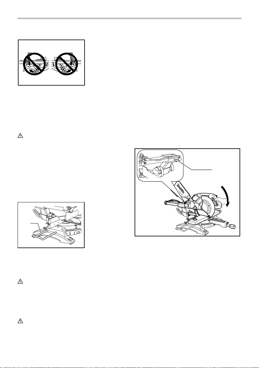
29. NEVER hold workpiece on right side of blade
with left hand or vice versa. This is called
cross-armed cutting and exposes user to risk
of SERIOUS PERSONAL INJURY as shown in
the figure. ALWAYS use vise to secure
workpiece.
000030
30. Do not abuse cord. Never yank cord to
disconnect it from the receptacle. Keep cord
away from heat, oil, water and sharp objects.
31. NEVER stack workpieces on the table top to
speed cutting operations. Cut only one piece
at a time.
32. Some material contains chemicals which may
be toxic. Take caution to prevent dust
inhalation and skin contact. Follow material
4
supplier safety data.
SAVE THESE INSTRUCTIONS.
WARNING:
MISUSE or failure to follow the safety rules stated in
this instruction manual may cause serious personal
injury.
USB088-2
ADDITIONAL SAFETY RULES
FOR THE LASER
CAUTION:
• LASER RADIATION DO NOT STARE INTO
BEAM.
• AVOID EXPOSURE - LASER RADIATION IS
EMITTED FROM APERTURE.
• USE OF CONTROLS OR ADJUSTMENTS OR
PERFORMANCE OF PROCEDURES OTHER
THAN THOSE SPECIFIED HEREIN MAY
RESULT IN HAZARDOUS RADIATION
EXPOSURE.
COMPLIES WITH 21CFR 1040.10 AND
1040.11
AVOID EXPOSURE – LASER RADIATIONS
IS EMITTED FROM THIS APERTURE
CONFORME A 21CFR 1040.10 ET 1040.11
EVITEZ L'EXPOSITION - UN
RAYONNEMENT LASER EST EMIS PAR
CETTE OUVERTURE.
CAUTION/ PRECAUCIÓN
LASER RADIATION DO NOT STARE INTO BEAM
RADIACIÓN LÁSER NO DIRIJA LA
VISTA HACIA EL RAYO LÁSER
Maximum Output
< 1mW, Wavelength : 660 nm
CLASS LASER PRODUCT
010401
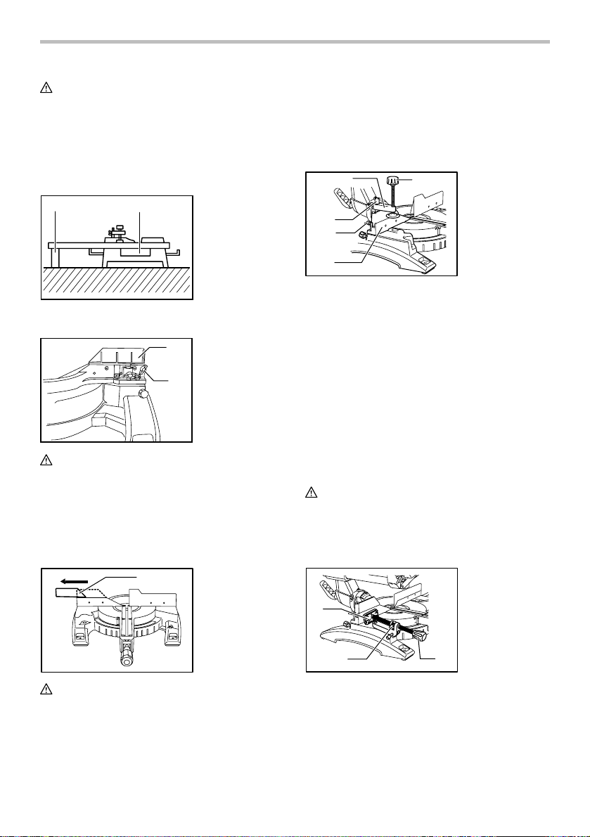
INSTALLATION
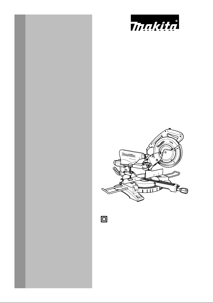
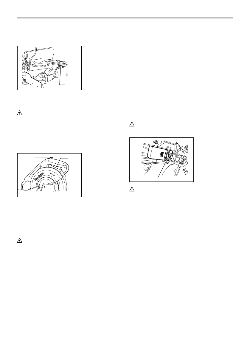
Bench mounting
1. Stopper pin
1
010228
When the tool is shipped, the handle is locked in the
lowered position by the stopper pin. Release the stopper
pin by lowering the handle slightly and pulling the stopper
pin.
1
010564
1. Bolt
This tool should be bolted with four bolts to a level and
stable surface using the bolt holes provided in the tool's
base. This will help prevent tipping and possible injury.
FUNCTIONAL DESCRIPTION
CAUTION:
• Always be sure that the tool is switched off and
unplugged before adjusting or checking function on
the tool.
Blade guard
1. Blade guard
1
010386
When lowering the handle, the blade guard rises
automatically. The blade guard returns to its original
position when the cut is completed and the handle is
raised. NEVER DEFEAT OR REMOVE THE BLADE
GUARD OR THE SPRING WHICH ATTACHES TO THE
GUARD.
In the interest of your personal safety, always maintain
the blade guard in good condition. Any irregular
operation of the blade guard should be corrected
immediately. Check to assure spring loaded return action
of guard. NEVER USE THE TOOL IF THE BLADE
GUARD OR SPRING ARE DAMAGED, FAULTY OR
REMOVED. DOING SO IS HIGHLY DANGEROUS AND
CAN CAUSE SERIOUS PERSONAL INJURY.
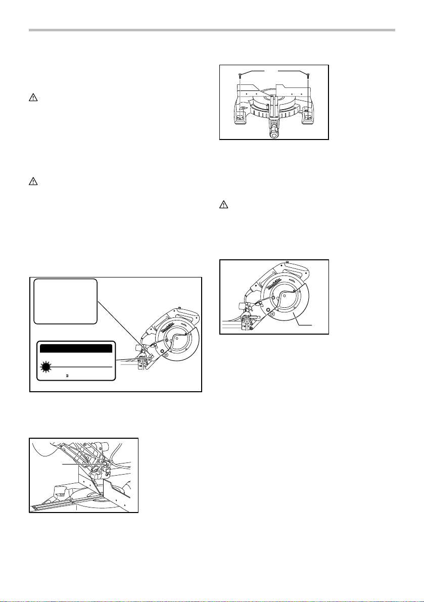
If the see-through blade guard becomes dirty, or sawdust
adheres to it in such a way that the blade and/or
workpiece is no longer easily visible, unplug the saw and
clean the guard carefully with a damp cloth. Do not use
solvents or any petroleum-based cleaners on the plastic
guard.
If the blade guard is especially dirty and vision through
the guard is impaired, use the supplied socket wrench to
loosen the hex bolt holding the center cover. Loosen the
5
hex bolt by turning it counterclockwise and raise the
blade guard and center cover. With the blade guard so
positioned, cleaning can be more completely and
efficiently accomplished. When cleaning is complete,
reverse procedure above and secure bolt. Do not remove
spring holding blade guard. If guard becomes discolored
through age or UV light exposure, contact a Makita
service center for a new guard. DO NOT DEFEAT OR
REMOVE GUARD.
1. Blade guard
1
010387
Positioning kerf board
1. Kerf board
2. Screw
boards so that the kerf boards just contact the sides of
blade teeth. Tighten the rear screws (do not tighten
firmly).
After adjusting the kerf boards, release the stopper pin
and raise the handle. Then tighten all the screws
securely.
CAUTION:
• Before and after changing the bevel angle, always
adjust the kerf boards as described above.
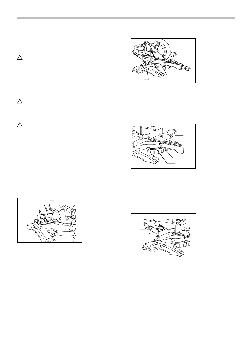
Maintaining maximum cutting capacity
Unplug the tool before any adjustment is attempted. This
tool is factory adjusted to provide the maximum cutting
capacity for a 255 mm (10") saw blade.
When installing a new blade, always check the lower limit
position of the blade and if necessary, adjust it as follows:
1
1. Adjusting bolt
2. Turn base
1
010384
2
12
3
45
001800
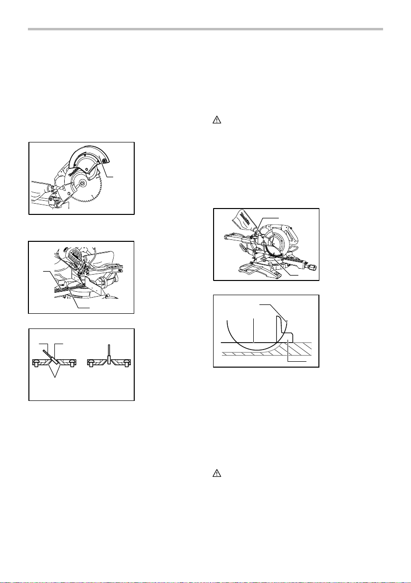
This tool is provided with the kerf boards in the turn base
to minimize tearing on the exit side of a cut. The kerf
boards are factory adjusted so that the saw blade does
not contact the kerf boards. Before use, adjust the kerf
boards as follows:
First, unplug the tool. Loosen all the screws (3 each on
left and right) securing the kerf boards. Re-tighten them
only to the extent that the kerf boards can still be easily
moved by hand. Lower the handle fully and push in the
stopper pin to lock the handle in the lowered position.
Loosen the screw which secures the slide poles. Pull the
carriage toward you fully. Adjust the kerf boards so that
the kerf boards just contact the sides of the blade teeth.
Tighten the front screws (do not tighten firmly). Push the
carriage toward the guide fence fully and adjust the kerf
1. Saw blade
2. Blade teeth
3. Kerf board
4. Left bevel cut
5. Straight cut
2
010402
2
1
001540
First, unplug the tool. Push the carriage toward the guide
fence fully and lower the handle completely. Use the hex.
wrench to turn the adjusting bolt until the periphery of the
blade extends slightly below the top surface of the turn
base at the point where the front face of the guide fence
meets the top surface of the turn base.
With the tool unplugged, rotate the blade by hand while
holding the handle all the way down to be sure that the
blade does not contact any part of the lower base.
Re-adjust slightly, if necessary.
CAUTION:
• After installing a new blade, always be sure that the
blade does not contact any part of the lower base
when the handle is lowered completely. Always do
this with the tool unplugged.
1. Top surface of
turn base
2. Periphery of
blade
3. Guide fence
3
6
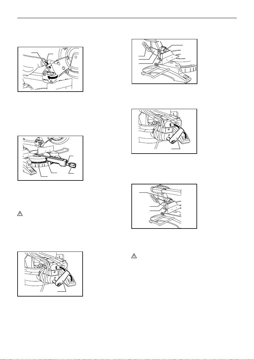
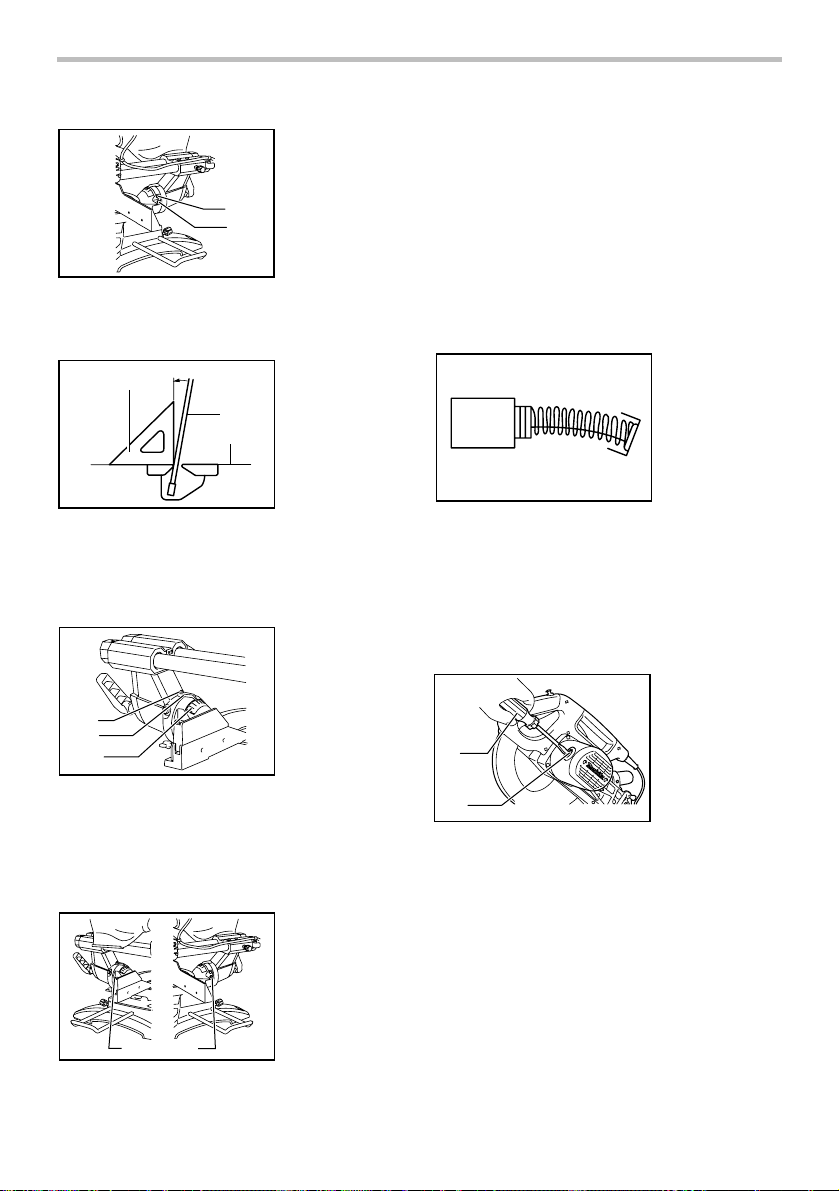
Stopper arm
1
1. Lever
4
2
1. Stopper arm
2. Adjusting screw
1
2
3
2. Arm
3. Pointer
4. Bevel scale
010233
The lower limit position of the blade can be easily
adjusted with the stopper arm. To adjust it, move the
stopper arm in the direction of the arrow as shown in the
figure. Adjust the adjusting screw so that the blade stops
at the desired position when lowering the handle fully.
Adjusting the miter angle
1. Miter scale
2. Pointer
3. Lock lever
4. Grip
3
4
2
1
010234
Loosen the grip by turning counterclockwise. Turn the turn base
while pressing down the lock lever. When you have moved the
grip to the position where the pointer points to the desired angle
on the miter scale, securely tighten the grip clockwise.
CAUTION:
• When turning the turn base, be sure to raise the
handle fully.
• After changing the miter angle, always secure the
turn base by tightening the grip firmly.
Adjusting the bevel angle
1. Lever
1
010236
To adjust the bevel angle, loosen the lever at the rear of
the tool counterclockwise. Unlock the arm by pushing the
handle somewhat strongly in the direction that you intend
to tilt the saw blade.
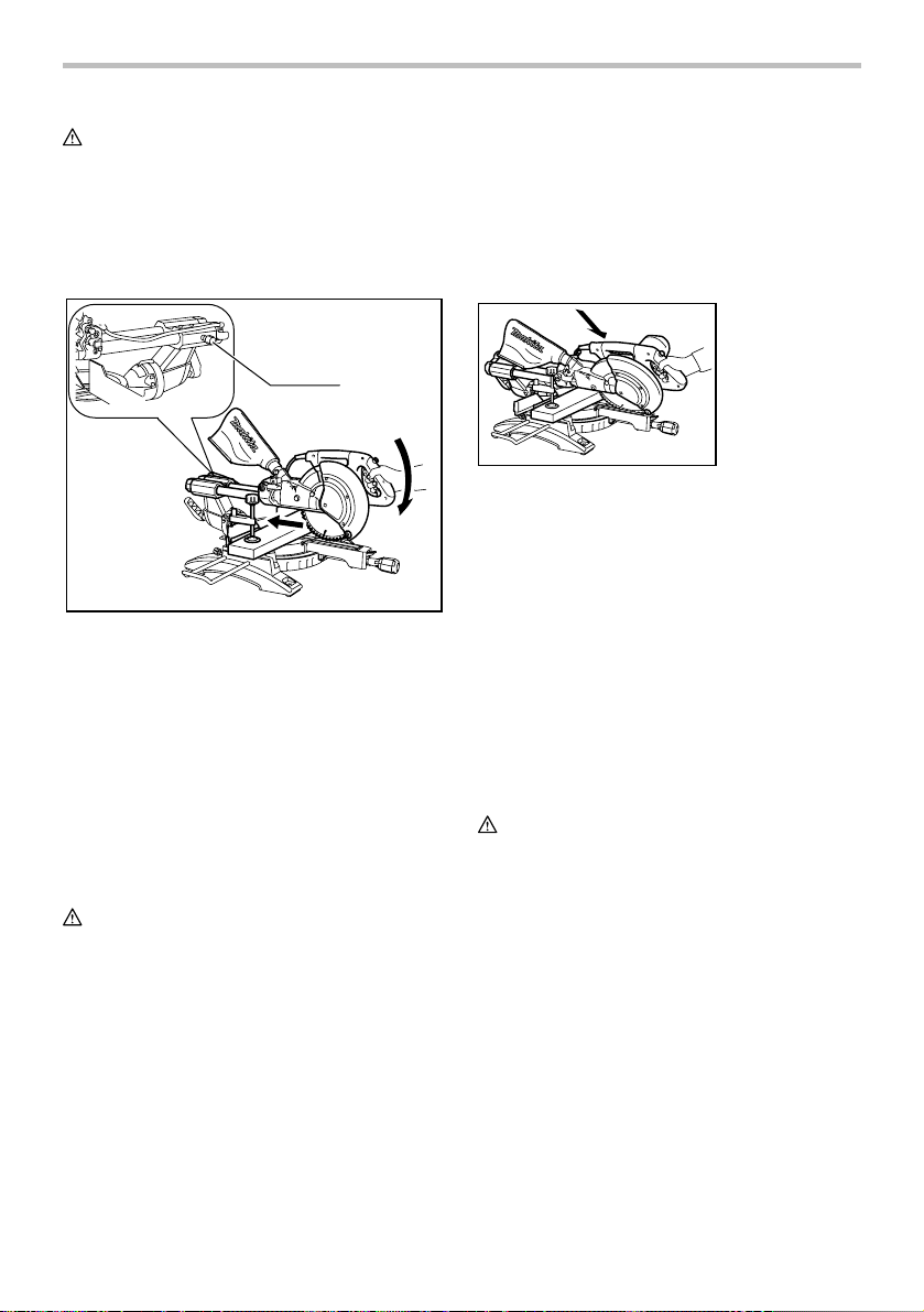
010235
Tilt the saw blade until the pointer points to the desired
angle on the bevel scale. Then tighten the lever
clockwise firmly to secure the arm.
1
010236
When tilting the carriage to the right, tilt the carriage to
the left slightly after loosening the lever and press the
releasing button. With the releasing button being pressed,
tilt the carriage to the right.
1
2
3
010430
Tilt the saw blade until the pointer points to the desired
angle on the bevel scale. Then tighten the lever
clockwise firmly to secure the arm.
CAUTION:
• When tilting the saw blade, be sure to raise the
handle fully.
• After changing the bevel angle, always secure the
arm by tightening the lever clockwise.
• When changing bevel angles, be sure to position
the kerf boards appropriately as explained in the
"Positioning kerf boards" section.
1. Lever
1. Pointer
2. Release button
3. Bevel scale
7
Slide lock adjustment
1. Locking screw
1
010428
To lock the slide pole, turn the locking screw clockwise.
Switch action
CAUTION:
• Before plugging in the tool, always check to see
that the switch trigger actuates properly and returns
to the "OFF" position when released.
• Do not pull the switch trigger hard without pressing
in the lock-off button. This can cause switch
breakage.
1
1. Lock-off button
2
2. Switch trigger
3. Hole for padlock
Electric brake
This tool is equipped with an electric blade brake. If the
tool consistently fails to quickly stop blade after switch
trigger release, have tool serviced at a Makita service
center.
The blade brake system is not a substitute for blade
guard. NEVER USE TOOL WITHOUT A FUNCTIONING
BLADE GUARD. SERIOUS PERSONAL INJURY CAN
RESULT.
Electronic function
Soft start feature
• Soft start because of suppressed starting shock.
Laser beam action
For model LS1017L only
CAUTION:
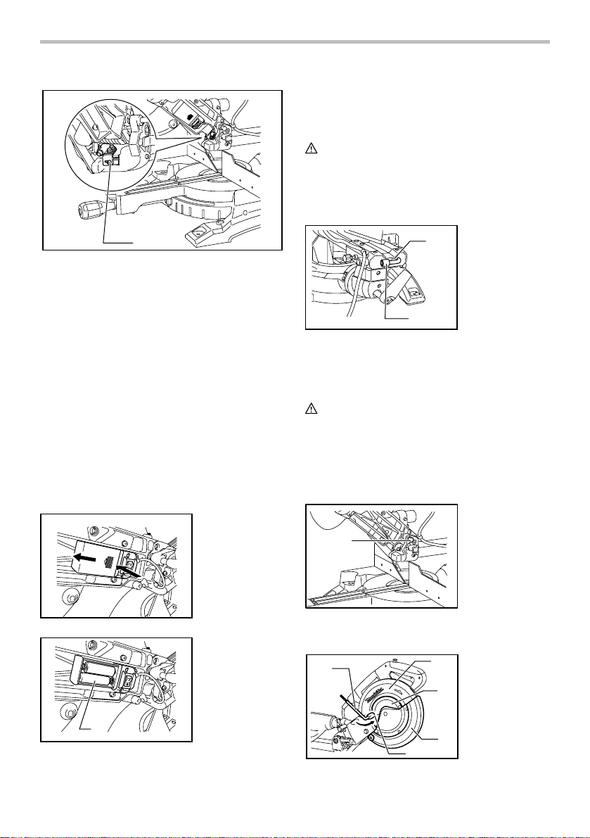
• When not in use, be sure to turn off the laser
1. Switch for laser
3
010388
To prevent the switch trigger from being accidentally
pulled, a lock-off button is provided. To start the tool,
press in the lock-off button and pull the switch trigger.
Release the switch trigger to stop.
A hole is provided in the switch trigger for insertion of
padlock to lock the tool off.
WARNING:
• Do not use a lock with a shank or cable any smaller
than 6.35 mm (1/4") in diameter.
• NEVER use tool without a fully operative switch
trigger. Any tool with an inoperative switch is
HIGHLY DANGEROUS and must be repaired
before further usage.
• For your safety, this tool is equipped with a lock-off
button which prevents the tool from unintended
starting. NEVER use the tool if it runs when you
simply pull the switch trigger without pressing the
lock-off button. Return tool to a Makita service
center for proper repairs BEFORE further usage.
• NEVER tape down or defeat purpose and function
of lock-off button.
010257
1
CAUTION:
• LASER RADIATION
Do not stare into beam.
• Before shifting the laser line or performing
maintenance adjustment, be sure to unplug the
tool.
To turn on the laser beam, press the upper position (I) of
the switch. Press the lower position (O) to turn off.
Laser line can be shifted to either the left or right side of
the saw blade by loosening the screw holding the laser
unit box and shifting it in the desired direction. After
shifting, be sure to tighten the screw.
8
1
x
1. Screw holding the laser unit bo
010389
Laser line is factory adjusted so that it is positioned within
1 mm (0.04") from the side surface of the blade (cutting
position).
Cleaning of the lens for the laser light
If the lens for the laser light becomes dirty, or sawdust
adheres to it in such a way that the laser line is no longer
easily visible, unplug the saw and remove and clean the
lens for the laser light carefully with a damp, soft cloth.
Do not use solvents or any petroleum-based cleaners on
the lens.
NOTE:
• When laser line is dim and almost or entirely
invisible because of the direct sunlight in the indoor
or outdoor window-by work, relocate the work area
to a place not exposed to the direct sunlight.
Replacing the dry cells for laser unit
new ones as shown in the figure. After replacing, return
the lid to cover it.
ASSEMBLY
CAUTION:
• Always be sure that the tool is switched off and
unplugged before carrying out any work on the tool.
Storage of socket wrench with hex wrench on
its other end
1. Socket wrench
2
1
010240
The socket wrench is stored as shown in the figure. When
using the socket wrench, pull it out of the wrench holder.
After using the socket wrench, return it to the wrench holder.
Installing or removing saw blade
CAUTION:
• Always be sure that the tool is switched off and
unplugged before installing or removing the blade.
• Use only the Makita socket wrench provided to
install or remove the blade. Failure to do so may
result in overtightening or insufficient tightening of
the hex bolt. This could cause an injury.
with hex wrench
on its other end
2. Wrench holder
1. Stopper pin
010399
1
010259
Remove the lid for the dry cells for laser unit by sliding
while pressing it. Take out the old dry cells and put the
1. Dry cell
1
010228
Lock the handle in the raised position by pushing in the
stopper pin.
1
010390
9
4
2
1. Socket wrench
2. Blade case
3. Center cover
3
4. Hex bolt
5. Blade guard
5
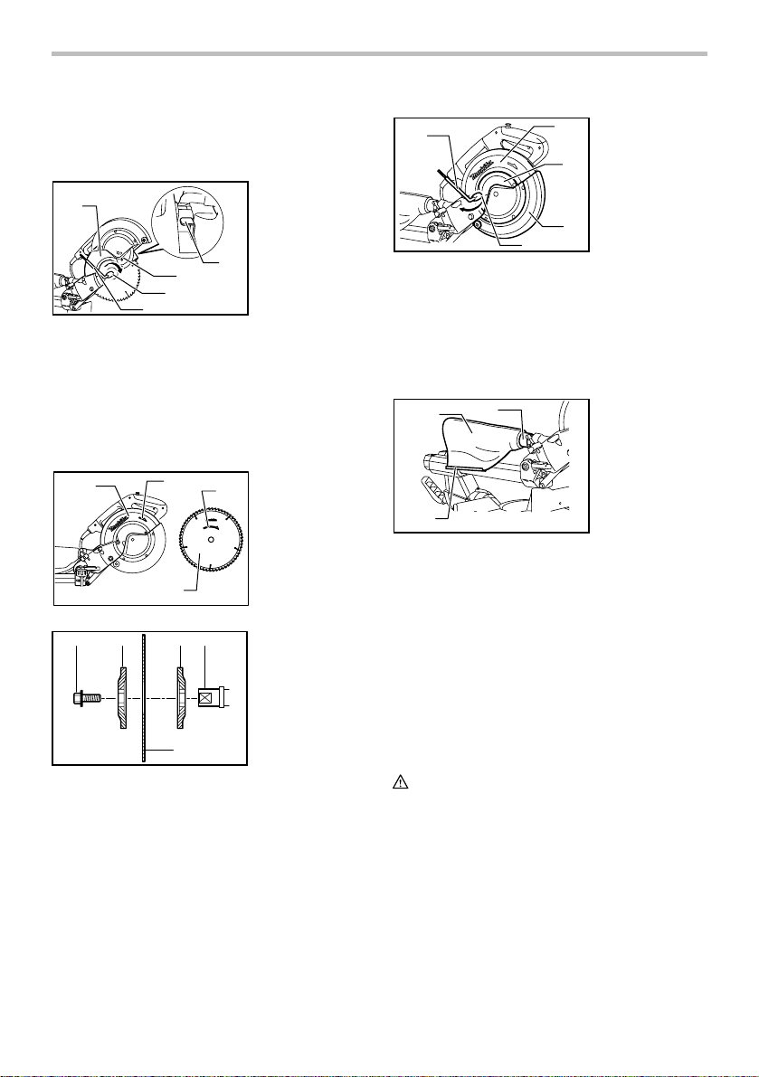
To remove the blade, use the socket wrench to loosen
the hex bolt holding the center cover by turning it
counterclockwise. Raise the blade guard and center
cover.
1. Blade case
2. Socket wrench
3. Hex bolt
4. Arrow
5. Shaft lock
5
010391
1
4
3
2
Press the shaft lock to lock the spindle and use the
socket wrench to loosen the hex bolt clockwise. Then
remove the hex bolt, outer flange and blade.
NOTE:
• When inner flange is removed mistakenly, be sure
to install it on the spindle with its protrusion facing
the spindle.
1
010392
12 435
001786
2
4
1. Blade case
3
2. Arrow
3. Arrow
4. Saw blade
1. Hex bolt
2. Outer flange
3. Saw blade
4. Inner flange
5. Spindle
To install the blade, mount it carefully onto the spindle,
making sure that the direction of the arrow on the surface
of the blade matches the direction of the arrow on the
blade case.
Install the outer flange and hex bolt, and then use the
socket wrench to tighten the hex bolt (left-handed)
securely counterclockwise while pressing the shaft lock.
2
1. Socket wrench
2. Blade case
3. Center cover
3
4. Hex bolt
5. Blade guard
5
010560
1
4
Return the blade guard and center cover to its original
position. Then tighten the hex bolt clockwise to secure
the center cover. Release the handle from the raised
position by pulling the stopper pin. Lower the handle to
make sure that the blade guard moves properly. Make
sure shaft lock has released spindle before making cut.
Dust bag (accessory)
2
3
010245
1
The use of the dust bag makes cutting operations clean
and dust collection easy. To attach the dust bag, fit it onto
the dust nozzle.
When the dust bag is about half full, remove the dust bag
from the tool and pull the fastener out. Empty the dust
bag of its contents, tapping it lightly so as to remove
particles adhering to the insides which might hamper
further collection.
NOTE:
If you connect a vacuum cleaner to your saw, more
efficient and cleaner operations can be performed.
Securing workpiece
WARNING:
• It is extremely important to always secure the
workpiece properly and tightly with the vise. Failure
to do so can cause the tool to be damaged and/or
the workpiece to be destroyed. PERSONAL
INJURY MAY ALSO RESULT. Also, after a cutting
operation, DO NOT raise the blade until the blade
has come to a complete stop.
1. Dust nozzle
2. Dust bag
3. Fastener
10
CAUTION:
• When cutting long workpieces, use supports that
are as high as the top surface level of the turn base.
Do not rely solely on the vertical vise and/or
horizontal vise to secure the workpiece.
Thin material tends to sag. Support workpiece over
its entire length to avoid blade pinch and possible
KICKBACK.
1
2
1. Support
2. Turn base
However, when performing left bevel cuts, set it to the left
position as shown in the figure if the tool head contacts it.
When bevel-cutting operations are complete, don't forget
to return the sliding fence to the original position and
secure it by firmly tightening the clamping screw.
Vertical vise
1
2
3
4
1. Vise arm
2. Vise knob
3. Vise rod
4. Screw
5. Guide fence
001549
Sliding fence adjustment
1. Sliding fence
1
2. Clamping screw
2
010480
WARNING:
• Before operating the tool, make sure that the sliding
fence is secured firmly.
• Before bevel-cutting, make sure that no part of the
tool contacts the sliding fence when lowering and
raising the handle fully at any position and pulling or
pushing the carriage all the way at the lowest
position..
1
010407
CAUTION:
• When performing bevel cuts, slide the sliding fence
to the left and secure it as shown in the figure.
Otherwise, it will contact the blade or a part of the
tool, causing possible serious injury to the operator.
This tool is equipped with the sliding fence which should
ordinarily be positioned as shown in the figure.
1. Sliding fence
5
010393
The vertical vise can be installed on either the left or right
side of the guide fence. Insert the vise rod into the hole in
the guide fence and tighten the screw on the back of the
guide fence to secure the vise rod.
Position the vise arm according to the thickness and
shape of the workpiece and secure the vise arm by
tightening the screw. If the screw to secure the vise arm
contacts the guide fence, install the screw on the
opposite side of vise arm. Make sure that no part of the
tool contacts the vise when lowering the handle fully and
pulling or pushing the carriage all the way. If some part
contacts the vise, re-position the vise.
Press the workpiece flat against the guide fence and the
turn base. Position the workpiece at the desired cutting
position and secure it firmly by tightening the vise knob.
CAUTION:
• The workpiece must be secured firmly against the
turn base and guide fence with the vise during all
operations.
Horizontal vise (optional accessory)
1. Vise plate
2. Vise nut
1
2
010299
The horizontal vise can be installed in two positions on
either the left or right side of the base. When performing
10° or greater miter cuts, install the horizontal vise on the
side opposite the direction in which the turn base is to be
turned.
11
3. Vise knob
3
005232
By flipping the vise nut to the left, the vise is released,
and rapidly moves in and out. To grip the workpiece,
push the vise knob forward until the vise plate contacts
the workpiece and flip the vise nut to the right. Then turn
the vise knob clockwise to secure the workpiece.
The maximum width of workpiece which can be secured
by the horizontal vise is 215 mm (8-1/2").
CAUTION:
• Always rotate the vise nut to the right fully when
securing the workpiece. Failure to do so may result
in insufficient securing of the workpiece. This could
cause the workpiece to be thrown, cause damage
to the blade or cause the loss of control, which can
result in PERSONAL INJURY.
• When cutting out thin workpiece, such as base
boards, against the fence, always use the
horizontal vise.
Holders
1. Holder
• Make sure the blade is not contacting the
workpiece, etc. before the switch is turned on.
• Do not apply excessive pressure on the handle
when cutting. Too much force may result in
overload of the motor and/or decreased cutting
efficiency. Push down handle with only as much
force as is necessary for smooth cutting and
without significant decrease in blade speed.
• Gently press down the handle to perform the cut. If
the handle is pressed down with force or if lateral
force is applied, the blade will vibrate and leave a
mark (saw mark) in the workpiece and the precision
of the cut will be impaired.
• During a slide cut, gently push the carriage toward
the guide fence without stopping. If the carriage
movement is stopped during the cut, a mark will be
left in the workpiece and the precision of the cut will
be impaired.
1. Press cutting (cutting small workpieces)
1
1
010255
The holders can be installed on either side as a
convenient means of holding workpieces horizontally.
Slip fully the holder rods into the holes in the base. Then
tighten the holders securely with the screws.
CAUTION:
• Always support long workpieces level with the top
surface of the turn base for accurate cuts and to
prevent dangerous loss of control of the tool.
OPERATION
CAUTION:
• Before use, be sure to release the handle from the
lowered position by pulling the stopper pin.
1. Locking screw
010394
Workpieces up to 91 mm (3-5/8") high and 70 mm
(2-3/4") wide can be cut in the following way.
Push the carriage toward the guide fence fully and
tighten the locking screw clockwise to secure the
carriage. Secure the workpiece with the vise.
Switch on the tool without the blade making any
contact and wait until the blade attains full speed
before lowering. Then gently lower the handle to
the fully lowered position to cut the workpiece.
When the cut is completed, switch off the tool and
WAIT UNTIL THE BLADE HAS COME TO A
COMPLETE STOP before returning the blade to its
fully elevated position.
12
CAUTION:
• Firmly tighten the knob clockwise so that the
carriage will not move during operation. Insufficient
tightening may cause unexpected kickback of the
blade. Possible serious PERSONAL INJURY may
result.
2. Slide (push) cutting (cutting wide workpieces)
1
• Never loosen the locking screw which secures the
carriage while the blade is rotating. This may cause
serious injury.
3. Miter cutting
Refer to the previously covered "Adjusting the miter
angle".
4. Bevel cut
1. Locking screw
010395
Loosen the locking screw counterclockwise so that
the carriage can slide freely. Secure the workpiece
with the vise. Pull the carriage toward you fully.
Switch on the tool without the blade making any
contact and wait until the blade attains full speed.
Press down the handle and PUSH THE
CARRIAGE TOWARD THE GUIDE FENCE AND
THROUGH THE WORKPIECE. When the cut is
completed, switch off the tool and WAIT UNTIL
THE BLADE HAS COME TO A COMPLETE STOP
before returning the blade to its fully elevated
position.
CAUTION:
• Whenever performing the slide cut, FIRST PULL
THE CARRIAGE TOWARD YOU FULLY and press
down the handle to the fully lowered position, then
PUSH THE CARRIAGE TOWARD THE GUIDE
FENCE. NEVER START THE CUT WITH THE
CARRIAGE NOT FULLY PULLED TOWARD YOU.
If you perform the slide cut without pulling the
carriage fully or if you perform the slide cut toward
your direction, the blade may kickback
unexpectedly with the potential to cause serious
PERSONAL INJURY.
• Never perform the slide cut with the handle locked
in the lowered position by pressing the stopper pin.
010396
Loosen the lever and tilt the saw blade to set the
bevel angle (Refer to the previously covered
"Adjusting the bevel angle"). Be sure to retighten
the lever firmly to secure the selected bevel angle
safely. Secure the workpiece with a vise. Make sure
the carriage is pulled all the way back toward the
operator. Switch on the tool without the blade
making any contact and wait until the blade attains
full speed. Then gently lower the handle to the fully
lowered position while applying pressure in parallel
with the blade and PUSH THE CARRIAGE
TOWARD THE GUIDE FENCE TO CUT THE
WORKPIECE. When the cut is completed, switch
off the tool and WAIT UNTIL THE BLADE HAS
COME TO A COMPLETE STOP before returning
the blade to its fully elevated position.
CAUTION:
• Always be sure that the blade will move down to
bevel direction during a bevel cut. Keep hands out
of path of saw blade.
• During a bevel cut, it may create a condition
whereby the piece cut off will come to rest against
the side of the blade. If the blade is raised while the
blade is still rotating, this piece may be caught by
the blade, causing fragments to be scattered which
is dangerous. The blade should be raised ONLY
after the blade has come to a complete stop.
• When pressing down the handle, apply pressure in
parallel with the blade. If a force is applied
perpendicularly to the turn base or if the pressure
direction is changed during a cut, the precision of
the cut will be impaired.
• Always slide the sliding fence so that it does not
interfere any part of the carriage when performing
bevel cuts.
13
5. Compound cutting
Compound cutting is the process in which a bevel
angle is made at the same time in which a miter
angle is being cut on a workpiece. Compound
cutting can be performed at angle shown in the
table.
Miter angle Bevel angle
Left and Right 0 - 45
010340
Left 0 - 45
When performing compound cutting, refer to "Press
cutting", "Slide cutting", "Miter cutting" and "Bevel
cut" explanations.
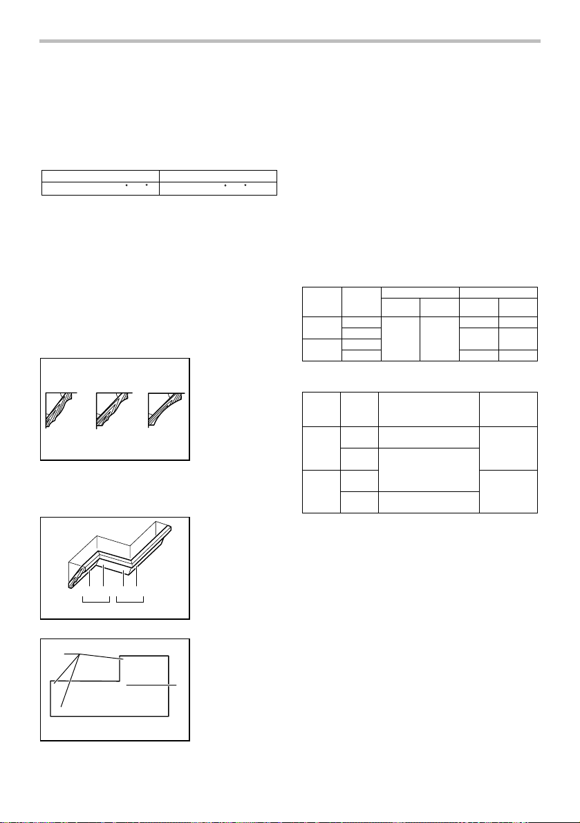
6. Cutting crown and cove moldings
Crown and cove moldings can be cut on a
compound miter saw with the moldings laid flat on
the turn base.
There are two common types of crown moldings
and one type of cove moldings; 52/38° wall angle
crown molding, 45° wall angle crown molding and
45° wall angle cove molding. See illustrations.
1. 52/38 ゚ type
crown molding
52
38
45
45
45
45
2. 45 ゚ type crown
molding
3. 45 ゚ type cove
molding
123
001555
There are crown and cove molding joints which are
made to fit "Inside" 90° corners ((1) and (2) in Fig.
A) and "Outside" 90° corners ((3) and (4) in Fig. A).
1. Inside corner
2. Outside corner
(1) (2) (3) (4)
Fig.A
001556
(1)
(2)
1 2
1
(2)
(1)
(2)
(1)
(4)
(3)
1. Inside corner
(2)
2
(1)
2. Outside corner
(1)
(2)
Measuring
Measure the wall length and adjust workpiece on
table to cut wall contact edge to desired length.
Always make sure that cut workpiece length at the
back of the workpiece is the same as wall length.
Adjust cut length for angle of cut. Always use
several pieces for test cuts to check the saw
angles.
When cutting crown and cove moldings, set the
bevel angle and miter angle as indicated in the
table (A) and position the moldings on the top
surface of the saw base as indicated in the table
(B).
In the case of left bevel cut
Molding
position in
Fig. A
For inside
corner
For outside
corner
006361
For inside
corner
For
outside
corner
006362
(1)
(2)
(3)
(4)
Molding
position in
Fig. A
(1)
(2)
(3)
(4)
Example:
In the case of cutting 52/38° type crown
molding for position (1) in Fig. A:
• Tilt and secure bevel angle setting to
• Adjust and secure miter angle setting to
• Lay crown molding with its broad back
• The finished piece to be used will
Table (A)
Bevel angleMiter angle
52/38° type 45° type
Left 33.9° Left 30°
52/38° type
Right 31.6°
45° type
Right 35.3°
Left 31.6° Left 35.3°
Right 35.3°Right 31.6°
Table (B)
Molding edge against
guide fence
Ceiling contact edge should
be against guide fence.
Wall contact edge should be
against guide fence
Ceiling contact edge should
be against guide fence
.
.
Finished piece
Finished piece
will be on the
Left side of
blade.
Finished piece
will be on the
Right side of
blade.
33.9° LEFT.
31.6° RIGHT.
(hidden) surface down on the turn base
with its CEILING CONTACT EDGE
against the guide fence on the saw.
always be on the LEFT side of the blade
after the cut has been made.
001557
14

Compound Miter Saw
Miter and Bevel Angle Settings
Ceiling
52°
38°
Wall
Wall to Crown Molding Angle: 52/38 degrees
Wall Angle
(deg.)
EN0002-1
Bevel Angle
60
61
62
63
64
65
66
67
68
69
70
71
72
73
74
75
76
77
78
79
80
81
82
83
84
85
86
87
88
89
90
91
92
93
94
95
96
97
98
99
100
(deg.)
43.0
42.8
42.5
42.2
41.9
41.7
41.4
41.1
40.8
40.5
40.2
39.9
39.6
39.3
39.0
38.7
38.4
38.1
37.8
37.4
37.1
36.8
36.5
36.2
35.8
35.5
35.2
34.9
34.5
34.2
33.9
33.5
33.2
32.8
32.5
32.2
31.8
31.5
31.1
30.8
30.4
Miter Angle
(deg.)
46.8
46.3
45.7
45.1
44.6
44.0
43.5
42.9
42.4
41.9
41.3
40.8
40.3
39.8
39.2
38.7
38.2
37.7
37.2
36.8
36.3
35.8
35.3
34.8
34.4
33.9
33.4
33.0
32.5
32.1
31.6
31.2
30.7
30.3
29.9
29.4
29.0
28.6
28.2
27.7
27.3
Wall Angle
(deg.)
Bevel Angle
101
102
103
4
10
105
106
107
108
109
110
111
112
113
114
115
116
117
118
119
120
121
122
123
124
125
126
127
128
129
130
131
132
133
134
135
136
137
138
139
140
(deg.)
30.1
29.7
29.4
29.0
28.7
28.3
28.0
27.6
27.2
26.9
26.5
26.1
25.8
25.4
25.0
24.7
24.3
23.9
23.6
23.2
22.8
22.5
22.1
21.7
21.3
21.0
20.6
20.2
19.8
19.5
19.1
18.7
18.3
17.9
17.6
17.2
16.8
16.4
16.0
15.6
Miter Angle
(deg.)
26.9
26.5
26.1
25.7
25.3
24.9
24.5
24.1
23.7
23.3
22.9
22.6
22.2
21.8
21.4
21.0
20.7
20.3
19.9
19.6
19.2
18.8
18.5
18.1
17.8
17.4
17.1
16.7
16.4
16.0
15.7
15.3
15.0
14.6
14.3
14.0
13.6
13.3
13.0
12.8
000031
Wall Angle
(deg.)
141
142
143
144
145
146
147
148
149
150
151
152
153
154
155
156
157
158
159
160
161
162
163
164
165
166
167
168
169
170
171
172
173
174
175
176
177
178
179
180
Bevel Angle
(deg.)
15.3
14.9
14.5
14.1
13.7
13.3
12.9
12.5
12.2
11.8
11.4
11. 0
10.8
10.2
9.8
9.4
9.0
8.6
8.3
7.9
7.5
7.1
6.7
6.3
5.9
5.5
5.1
4.7
4.3
3.9
3.5
3.2
2.8
2.4
2.0
1.6
1.2
0.8
0.4
0.0
Miter Angle
(deg.)
12.3
12.0
11.6
11.3
11. 0
10.7
10.3
10.0
9.7
9.4
9.0
8.7
8.4
8.1
7.8
7.5
7.1
6.8
6.5
6.2
5.9
5.6
5.3
4.9
4.6
4.3
4.0
3.7
3.4
3.1
2.8
2.5
2.2
1.8
1.5
1.2
0.9
0.6
0.3
0.0
15

Compound Miter Saw
Miter and Bevel Angle Settings
Ceiling
45°
45°
Wall
Wall to Crown Molding Angle: 45 degrees
Wall Angle
EN0003-1
(deg.)
Bevel Angle
60
61
62
63
64
65
66
67
68
69
70
71
72
73
74
75
76
77
78
79
80
81
82
83
84
85
86
87
88
89
90
91
92
93
94
95
96
97
98
99
100
(deg.)
37.8
37.5
37.3
37.1
36.8
36.6
36.4
36.1
35.9
35.6
35.4
35.1
34.9
34.6
34.4
34.1
33.9
33.6
33.3
33.1
32.8
32.5
32.3
32.0
31.7
31.4
31.1
30.9
30.6
30.3
30.0
29.7
29.4
29.1
28.8
28.5
28.2
27.9
27.6
27.3
27.0
Miter Angle
(deg.)
50.8
50.2
49.6
49.1
48.5
48.0
47.4
46.9
46.4
45.8
45.3
44.8
44.2
43.7
43.2
42.7
42.1
41.6
41.1
40.6
40.1
39.6
39.1
38.6
38.1
37.7
37.2
36.7
36.2
35.7
35.3
34.8
34.3
33.9
33.4
32.9
32.5
32.0
31.6
31.1
30.7
Wall Angle
(deg.)
101
102
103
104
105
106
107
1
109
110
111
112
113
114
115
116
117
118
119
120
121
122
123
124
125
126
127
128
129
130
131
132
133
134
135
136
137
138
139
140
Bevel Angle
(deg.)
08
26.7
26.4
26.1
25.8
25.5
25.2
24.9
24.6
24.2
23.9
23.6
23.3
23.0
22.7
22.3
22.0
21.7
21.4
21.0
20.7
20.4
20.0
19.7
19.4
19.1
18.7
18.4
18.1
17.7
17.4
17.1
16.7
16.4
16.0
15.7
15.4
15.0
14.7
14.3
14.0
Miter Angle
(deg.)
30.2
29.8
29.4
28.9
28.5
28.1
27.6
27.2
26.8
26.3
25.9
25.5
25.1
24.7
24.3
23.8
23.4
23.0
22.6
22.2
21.8
21.4
21.0
20.6
20.2
19.8
19.4
19.0
18.6
18.2
17.9
17.5
17.1
16.7
16.3
15.9
15.6
15.2
14.8
14.4
000032
Wall Angle
(deg.)
141
142
143
144
145
146
147
148
149
150
151
152
153
154
155
156
157
1
159
160
161
162
163
164
165
166
167
168
169
170
171
172
173
174
175
176
177
178
179
180
Bevel Angle
(deg.)
58
13.7
13.3
13.0
12.6
12.3
11. 9
11. 6
11. 2
10.9
10.5
10.2
9.8
9.5
9.2
8.8
8.5
8.1
7.8
7.4
7.1
6.7
6.4
6.0
5.6
5.3
4.9
4.6
4.2
3.9
3.5
3.2
2.8
2.5
2.1
1.8
1.4
1.1
0.7
0.4
0.0
Miter Angle
(deg.)
14.1
13.7
13.3
12.9
12.6
12.2
11. 8
11. 5
11. 1
10.7
10.4
10.0
9.6
9.3
8.9
8.5
8.2
7.8
7.5
7.1
6.7
6.4
6.0
5.7
5.3
5.0
4.6
4.3
3.9
3.5
3.2
2.8
2.5
2.1
1.8
1.4
1.1
0.7
0.4
0.0
16
7. Cutting aluminum extrusion
1. Guide fence
2. Vise
3. Spacer block
2
4. Aluminum
extrusion
5. Spacer block
1. Aluminum
extrusion
2. Guide fence
3. Spacer block
4. Horizontal vise
(optional
accessory)
010404
010469
3
4
1
1
2
5
3
4
When securing aluminum extrusions, use spacer
blocks or pieces of scrap as shown in the figure to
prevent deformation of the aluminum. Use a cutting
lubricant when cutting the aluminum extrusion to
prevent build-up of the aluminum material on the
blade.
CAUTION:
• Never attempt to cut thick or round aluminum
extrusions. Thick aluminum extrusions may come
loose during operation and round aluminum
extrusions cannot be secured firmly with this tool.
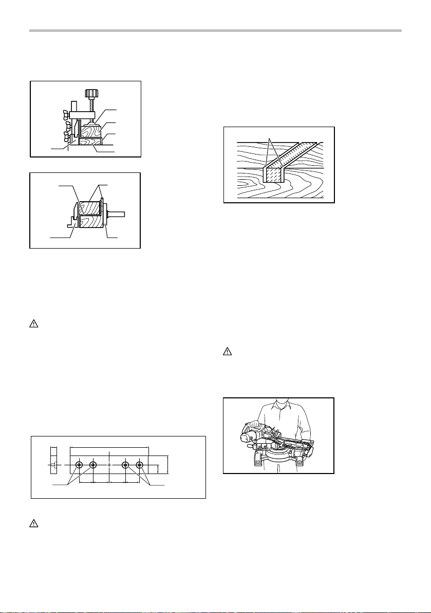
8. Wood facing
Use of wood facing helps to assure splinter-free
cuts in workpieces. Attach a wood facing to the
guide fence using the holes in the guide fence.
See the figure concerning the dimensions for a
suggested wood facing.
screw heads are below the surface of the wood
facing.
• When the wood facing is attached, do not turn the
turn base with the handle lowered. The blade
and/or the wood facing will be damaged.
9. Groove cutting
1
001563
1. Cut grooves with
blade
A dado type cut can be made by proceeding as
follows:
Adjust the lower limit position of the blade using the
adjusting screw and the stopper arm to limit the
cutting depth of the blade. Refer to "Stopper arm"
section described previously.
After adjusting the lower limit position of the blade,
cut parallel grooves across the width of the
workpiece using a slide (push) cut as shown in the
figure. Then remove the workpiece material
between the grooves with a chisel. Do not attempt
to perform this type of cut using wide (thick) blades
or with a dado blade. Possible loss of control and
injury may result.
CAUTION:
• Be sure to return the stopper arm to the original
position when performing other than groove cutting.
Carrying tool
15mm (9/16") Over 500 mm (19-3/4")
80mm-90mm
(3-1/8"-3-1/2")
1
1. Holes
010535
68mm
(2-11/16")
121mm
(4-3/4")
121mm
(4-3/4")
68mm
(2-11/16")
24 mm (15/16")
1
CAUTION:
• Use straight wood of even thickness as the wood
facing.
• Use screws to attach the wood facing to the guide
fence. The screws should be installed so that the
010397
Make sure that the tool is unplugged. Secure the blade at
0° bevel angle and the turn base at right miter angle fully.
Secure the slide poles after pulling the carriage toward
you fully. Lower the handle fully and lock it in the lowered
position by pushing in the stopper pin.
Wind the power supply cord using the cord rests.
Carry the tool by holding the tool base as shown in the
figure. If you remove the holders, dust bag, etc., you can
carry the tool more easily.
17
Carry the tool by holding both sides of the tool base as
shown in the figure. If you remove the holders, dust bag,
etc., you can carry the tool more easily.
CAUTION:
• Always secure all moving portions before carrying
the tool.
• Stopper pin is for carrying and storage purposes
only and not for any cutting operations.
MAINTENANCE
CAUTION:
• Always be sure that the tool is switched off and
unplugged before attempting to perform inspection
or maintenance.
WARNING:
• Always be sure that the blade is sharp and clean for
the best and safest performance.
NOTICE:
• Never use gasoline, benzine, thinner, alcohol or the
like. Discoloration, deformation or cracks may
result.
Adjusting the cutting angle
This tool is carefully adjusted and aligned at the factory,
but rough handling may have affected the alignment. If
your tool is not aligned properly, perform the following:
1. Miter angle
1
3
2
010251
Push the carriage toward the guide fence and
tighten the locking screw to secure the carriage.
Loosen the grip which secures the turn base. Turn
the turn base so that the pointer points to 0° on the
miter scale. Then turn the turn base slightly
clockwise and counterclockwise to seat the turn
base in the 0° miter notch. (Leave as it is if the
pointer does not point to 0°.) Loosen the hex
sockets bolts securing the guide fence using the
socket wrench.
1. Guide fence
2. Hex bolts
3. Grip
1. Guide fence
2. Triangular rule
2
010398
1
Lower the handle fully and lock it in the lowered
position by pushing in the stopper pin. Square the
side of the blade with the face of the guide fence
using a triangular rule, try-square, etc. Then
securely tighten the hex socket bolts on the guide
fence in the order from the right side.
1. Screw
2. Pointer
1
3. Miter scale
2
3
010432
Make sure that the pointer points to 0° on the miter
scale. If the pointer does not point to 0°, loosen the
screw which secures the pointer and adjust the
pointer so that it will point to 0°.
2. Bevel angle
(1) 0° bevel angle
1. Lever
2. Arm
1
2
010260
Push the carriage toward the guide fence and
tighten the locking screw to secure the
carriage. Lower the handle fully and lock it in
the lowered position by pushing in the stopper
pin. Loosen the lever at the rear of the tool.
18
010482
1. 0 ゚ adjusting
bolt
2. Left 45 ゚ bevel
angle adjusting
1
2
bolt
Turn the hex bolt on the right side of the arm
two or three revolutions counterclockwise to
tilt the blade to the right.
1
2
3
1. Triangular rule
2. Saw blade
3. Top surface of
turn base
Adjust the 45° bevel angle only after
performing 0° bevel angle adjustment. To
adjust left 45° bevel angle, loosen the lever
and tilt the blade to the left fully. Make sure
that the pointer on the arm points to 45° on
the bevel scale on the arm holder. If the
pointer does not point to 45°, turn the 45°
bevel angle adjusting bolt on the right side of
the arm holder until the pointer points to 45°.
To adjust the right 5° bevel angle, perform
the same procedure as that described above.
Replacing carbon brushes
001819
010261
010483
Carefully square the side of the blade with the
top surface of the turn base using the
triangular rule, try-square, etc. by turning the
hex bolt on the right side of the arm clockwise.
Then tighten the lever securely.
1
2
3
Make sure that the pointer on the arm point to
0° on the bevel scale on the arm holder. If
they do not point to 0°, loosen the screw
which secure the pointer and adjust it so that
it will point to 0°.
(2) 45° bevel angle
1
1. Screw
2. Pointer
3. Bevel scale
007834
Remove and check the carbon brushes regularly.
Replace when they wear down to 3 mm in length. Keep
the carbon brushes clean and free to slip in the holders.
Both carbon brushes should be replaced at the same
time. Use only identical carbon brushes.
Use a screwdriver to remove the brush holder caps. Take
out the worn carbon brushes, insert the new ones and
secure the brush holder caps.
1
1. Screwdriver
2. Brush holder
cap
2
010256
After replacing brushes, plug in the tool and break in
brushes by running tool with no load for about 10 minutes.
Then check the tool while running and electric brake
operation when releasing the switch trigger. If electric
1. Right 5 ゚ bevel
angle adjusting
bolt
2. Left 45 ゚ bevel
angle adjusting
bolt
2
brake is not working well, ask your local Makita service
center for repair.
After use
• After use, wipe off chips and dust adhering to the
tool with a cloth or the like. Keep the blade guard
clean according to the directions in the previously
covered section titled "Blade guard". Lubricate the
sliding portions with machine oil to prevent rust.
• When storing the tool, pull the carriage toward you
fully.
19

To maintain product SAFETY and RELIABILITY, repairs,
any other maintenance or adjustment should be
performed by Makita Authorized or Factory Service
Centers, always using Makita replacement parts.
ACCESSORIES
CAUTION:
• These accessories or attachments are
recommended for use with your Makita tool
specified in this manual. The use of any other
accessories or attachments might present a risk of
injury to persons. Only use accessory or
attachment for its stated purpose.
If you need any assistance for more details regarding
these accessories, ask your local Makita Service Center.
• Steel & Carbide-tipped saw blades
Miter saw blades
Combination
Crosscutting
Fine cross cutsFor sand-free cuts cleanly against
Non-ferrous metals
miter saw blades
006526
Vise assembly (Horizontal vise)
•
• Ve rtical vise
• Socket wrench with hex wrench on its other end
• Holder
• Dust bag
• Elbow
• Triangular rule
For smooth and precise cutting in various materials.
General purpose blade for fast and smooth rip,
crosscuts and miters.
For smoother cross grain cuts. Slices cleanly
against the grain.
the grain.
For miters in aluminum, copper, brass, tubing,
and other non-ferrous metals.
MAKITA LIMITED ONE YEAR WARRANTY
Warranty Policy
Every Makita tool is thoroughly inspected and tested
before leaving the factory. It is warranted to be free of
defects from workmanship and materials for the period
of ONE YEAR from the date of original purchase.
Should any trouble develop during this one year period,
return the COMPLETE tool, freight prepaid, to one of
Makita’s Factory or Authorized Service Centers. If
inspection shows the trouble is caused by defective
workmanship or material, Makita will repair (or at our
option, replace) without charge.
This Warranty does not apply where:
repairs have been made or attempted by others:
repairs are required because of normal wear and
tear:
the tool has been abused, misused or improperly
maintained:
alterations have been made to the tool.
IN NO EVENT SHALL MAKITA BE LIABLE FOR ANY
INDIRECT, INCIDENTAL OR CONSEQUENTIAL
DAMAGES FROM THE SALE OR USE OF THE
PRODUCT. THIS DISCLAIMER APPLIES BOTH
DURING AND AFTER THE TERM OF THIS
WARRANTY.
MAKITA DISCLAIMS LIABILITY FOR ANY IMPLIED
WARRANTIES, INCLUDING IMPLIED WARRANTIES
OF "MERCHANTABILITY" AND "FITNESS FOR A
SPECIFIC PURPOSE," AFTER THE ONE YEAR TERM
OF THIS WARRANTY.
This Warranty gives you specific legal rights, and you
may also have other rights which vary from state to
state. Some states do not allow the exclusion or
limitation of incidental or consequential damages, so
the above limitation or exclusion may not apply to you.
Some states do not allow limitation on how long an
implied warranty lasts, so the above limitation may not
apply to you.
EN0006-1
20

FRANÇAIS (Mode d’emploi original)
SPÉCIFICATIONS
Modèle LS1017 /LS1017L
Diamètre de la lame 255 mm (10")
Diamètre de l'orifice 15,88 mm (5/8")
Capacités de coupe maximales (H x P)
Angle de coupe d'onglet
0°
45°
60° (droite)
Vitesse à vide (T/MIN) 4 200/min.
Type de laser (LS1017L uniquement) Longueur d'ondes 660 nm, sortie maximale 1mW (Laser Classe II)
Dimensions (L x P x H) 825 mm x 536 mm x 581 mm
(32-1/2" x 21-1/8" x 22-7/8")
Poids net 19,4 kg (42,8 lbs)
• Étant donné l'évolution constante de notre programme de recherche et de développement, les spécifications contenues dans ce
manuel sont sujettes à modification sans préavis.
• Les spécifications peuvent varier suivant les pays.
• Poids conforme à la procédure EPTA du 01/2003
45° (gauche) 0°
50 mm x 305 mm 91 mm x 305 mm
(2" x 12") (3-5/8" x 12")
(gauche) 50 mm x 200 mm
(2" x 7-7/8") 91 mm x 215 mm
(droite) 50 mm x 215 mm (3-5/8" x 8-1/2")
(2" x 8-1/2")
USA007-2
Pour votre propre sécurité,
veuillez lire le manuel
d'instructions
Avant d'utiliser l'outil
Conservez-le pour référence
ultérieure
PRÉCAUTIONS GÉNÉRALES
(POUR TOUS LES OUTILS)
1. VOUS DEVEZ CONNAÎTRE VOTRE OUTIL
ÉLECTRIQUE. Lisez attentivement le manuel
d'instructions. Familiarisez-vous avec les
applications et limites de l'outil, ainsi qu'avec
les risques potentiels qui lui sont spécifiques.
2. MAINTENEZ LES PROTECTEURS EN PLACE
et en bon état de fonctionnement.
3. RETIREZ LES CLÉS DE RÉGLAGE ET DE
SERRAGE. Prenez l'habitude de vous assurer
que les clés de réglage et de serrage ont été
Angle de coupe en biseau
- 91 mm x 150 mm
(3-5/8" x 5-7/8")
retirées de l'outil avant de le mettre sous
tension.
4. MAINTENEZ LA ZONE DE TRAVAIL PROPRE.
Les zones de travail et les établis encombrés
ouvrent grande la porte aux accidents.
5. ÉVITEZ L'UTILISATION DANS UN
ENVIRONNEMENT DANGEREUX. N'utilisez
pas les outils électriques dans les endroits
humides ou mouillés, et ne les exposez pas à
la pluie. Maintenez un éclairage adéquat dans
la zone de travail. Ne vous servez pas de votre
outil en présence de liquides ou gaz
inflammables.
6. MAINTENEZ LES ENFANTS À L'ÉCART. Toute
autre personne que l'utilisateur de l'outil doit
se tenir à une distance sûre de l'aire de travail.
7. FAITES EN SORTE QUE L'ATELIER SOIT
SANS DANGER POUR LES ENFANTS, en y
posant des cadenas, un interrupteur principal,
ou en retirant des équipements leurs clés de
démarrage.
8. NE FORCEZ PAS L'OUTIL. Il effectuera un
travail de meilleure qualité et plus sécuritaire
s'il est utilisé au régime pour lequel il a été
conçu.
21
 Loading...