

Page 1
INSTRUCTION MANUAL
MANUEL D'INSTRUCTION
MANUAL DE INSTRUCCIONES
Slide Compound Miter Saw
Scie à Onglet Radiale
Sierra de Inglete Telescópica
LS1016
LS1016L
009482
DOUBLE INSULATION
DOUBLE ISOLATION
DOBLE AISLAMIENTO
WARNING:
For your personal safety, READ and UNDERSTAND before using.
SAVE THESE INSTRUCTIONS FOR FUTURE REFERENCE.
AVERTISSEMENT:
Pour votre propre sécurité, prière de lire attentivement avant l'utilisation.
GARDER CES INSTRUCTIONS POUR RÉFÉRENCE ULTÉRIEURE.
ADVERTENCIA:
Para su seguridad personal, LEA DETENIDAMENTE este manual antes de usar la
herramienta.
GUARDE ESTAS INSTRUCCIONES PARA FUTURA REFERENCIA.
1
Page 2

ENGLISH
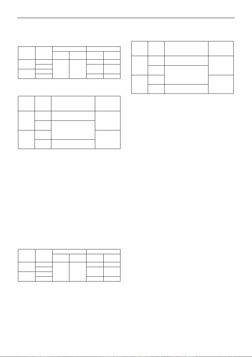
SPECIFICATIONS
Model LS1016/LS1016L
Blade diameter 255 mm (10")
Hole diameter 15.88 mm (5/8")
Max. Cutting capacities (H x W)
Miter angle
0°
45° (left) 0° 45° (right)
47 mm x 305 mm
(1-7/8"x12")
61 mm x 279 mm
(2-3/8"x11")
47 mm x 215 mm
45°(right and left)
(1-7/8"x 8-1/2")
61 mm x 197 mm
(2-3/8"x 7-3/4")
52°(right and left) -
60°(right) -
Special Max. Cutting capacities
Crown molding 45 ° type
(with Crown molding stopper used)
Base board (H)
(with Horizontal vise used)
No load speed (RPM) 3,200/min.
Laser Type (LS1016L only)
Wavelength 650 nm, Maximum output 1mW (Laser Class II)
Dimensions (L x W x H) 718 mm x 640 mm x 671 mm
(28-1/4" x 25-1/4"x 26-1/2")
Net weight 23.7 kg (52.2 lbs)
• Due to our continuing programme of research and development, the specifications herein are subject to change without notice.
• Note: Specifications may differ from country to country.
• Weight according to EPTA-Procedure 01/2003
2
Bevel angle
71 mm x 305 mm
(2-13/16"x12")
91 mm x 279 mm
(3-5/8"x11")
71 mm x 215 mm
(2-13/16"x 8-1/2")
91 mm x 197 mm
(3-5/8"x 7-3/4")
25 mm x 187 mm
(1"x 7-3/8")
91 mm x 91 mm
(3-5/8"x 3-5/8")
25 mm x 152 mm
(1"x 6")
91 mm x 76 mm
(3-5/8"x 3")
168 mm (6-5/8")
120 mm (4-3/4")
29 mm x 305 mm
(1-1/8"x12")
43 mm x 279 mm
(1-11/16"x11")
29 mm X 215 mm
(1-1/8"x 8-1/2")
43 mm x 197 mm
(1-11/16"x 7-3/4")
-
-
Page 3

USA007-2
For Your Own Safety Read
Instruction Manual
Before Operating Tool
Save it for future reference
GENERAL SAFETY
PRECAUTIONS
(FOR ALL TOOLS)
1. KNOW YOUR POWER TOOL. Read the owner's
manual carefully. Learn the tool's applications
and limitations, as well as the specific
potential hazards peculiar to it.
2. KEEP GUARDS IN PLACE and in working
order.
3. REMOVE ADJUSTING KEYS AND WRENCHES.
Form habit of checking to see that keys and
adjusting wrenches are removed from tool
before turning it on.
4. KEEP WORK AREA CLEAN. Cluttered areas
and benches invite accidents.
5. DO NOT USE IN DANGEROUS ENVIRONMENT.
Do not use power tools in damp or wet
locations, or expose them to rain. Keep work
area well lighted. Do not use tool in presence
of flammable liquids or gases.
6. KEEP CHILDREN AWAY. All visitors should be
kept safe distance from work area.
7. MAKE WORKSHOP KID PROOF with padlocks,
master switches, or by removing starter keys.
8. DO NOT FORCE TOOL. It will do the job better
and safer at the rate for which it was designed.
9. USE RIGHT TOOL. Do not force tool or
attachment to do a job for which it was not
designed.
10. WEAR PROPER APPAREL. Do not wear loose
clothing, gloves, neckties, rings, bracelets, or
other jewelry which may get caught in moving
parts. Nonslip footwear is recommended.
Wear protective hair covering to contain long
hair.
11. ALWAYS USE SAFETY GLASSES. Also use
face or dust mask if cutting operation is dusty.
Everyday eyeglasses only have impact
resistant lenses, they are NOT safety glasses.
12. SECURE WORK. Use clamps or a vise to hold
work when practical. It's safer than using your
hand and it frees both hands to operate tool.
13. DO NOT OVERREACH. Keep proper footing
and balance at all times.
14. MAINTAIN TOOLS WITH CARE. Keep tools
sharp and clean for best and safest
performance. Follow instructions for
lubricating and changing accessories.
15. DISCONNECT TOOLS before servicing; when
changing accessories such as blades, bits,
cutters, and the like.
16. REDUCE THE RISK OF UNINTENTIONAL
STARTING. Make sure switch is in off position
before plugging in.
17. USE RECOMMENDED ACCESSORIES.
Consult the owner's manual for recommended
accessories. The use of improper accessories
may cause risk of injury to persons.
18. NEVER STAND ON TOOL. Serious injury could
occur if the tool is tipped or if the cutting tool
is unintentionally contacted.
19. CHECK DAMAGED PARTS. Before further use
of the tool, a guard or other part that is
damaged should be carefully checked to
determine that it will operate properly and
perform its intended function - check for
alignment of moving parts, binding of moving
parts, breakage of parts, mounting, and any
other conditions that may affect its operation.
A guard or other part that is damaged should
be properly repaired or replaced.
20. DIRECTION OF FEED. Feed work into a blade
or cutter against the direction of rotation of
the blade or cutter only.
21. NEVER LEAVE TOOL RUNNING UNATTENDED.
TURN POWER OFF. Do not leave tool until it
comes to a complete stop.
22. REPLACEMENT PARTS. When servicing, use
only identical replacement parts.
23. POLARIZED PLUGS. To reduce the risk of
electric shock, this appliance has a polarized
plug (one blade is wider than the other). This
plug will fit in a polarized outlet only one way.
If the plug does not fit fully in the outlet,
reverse the plug. If it still does not fit, contact
a qualified electrician to install the proper
outlet. Do not change the plug in any way.
3
Page 4

VOLTAGE WARNING: Before connecting the tool to
a power source (receptacle, outlet, etc.) be sure the
voltage supplied is the same as that specified on the
nameplate of the tool. A power source with voltage
greater than that specified for the tool can result in
SERIOUS INJURY to the user- as well as damage to
the appliance. If in doubt, DO NOT PLUG IN THE
APPLIANCE. Using a power source with voltage less
than the nameplate rating is harmful to the motor.
USE PROPER EXTENSION CORD. Make sure your
extension cord is in good condition. When using an
extension cord, be sure to use one heavy enough to
carry the current your product will draw. An
undersized cord will cause a drop in line voltage
resulting in loss of power and overheating. Table 1
shows the correct size to use depending on cord
length and nameplate ampere rating. If in doubt, use
the next heavier gage. The smaller the gage number,
the heavier the cord.
Table 1: Minimum gage for cord
Ampere Rating
Volts Total length of cord in feet
120 V 25 ft. 50 ft. 100 ft. 150 ft.
More Than Not More Than AWG
0 6 18 16 16 14
18 16 14 12610
10 12 16 16 14 12
000173
ADDITIONAL SAFETY RULES
DO NOT let comfort or familiarity with product
(gained from repeated use) replace strict adherence
to slide compound saw safety rules. If you use this
tool unsafely or incorrectly, you can suffer serious
personal injury.
1. Wear eye protection.
2. Keep hands out of path of saw blade. Avoid
3. Do not operate saw without guards in place.
4. Do not perform any operation freehand. The
5. Never reach around saw blade.
6. Turn off tool and wait for saw blade to stop
7. Unplug tool before changing blade or
8. To reduce the risk of injury, return carriage to
12 16 14 12
USB036-2
contact with any coasting blade. It can still
cause severe injury.
Check blade guard for proper closing before
each use. Do not operate saw if blade guard
does not move freely and close instantly.
Never clamp or tie the blade guard into the
open position.
workpiece must be secured firmly against the
turn base and guide fence with a vise during
all operations. Never use your hand to secure
the workpiece.
before moving workpiece or changing
settings.
servicing.
the full rear position after each crosscut
operation.
9. Always secure all moving portions before
carrying the tool.
10. Stopper pin which locks the cutter head down
is for carrying and storage purposes only and
not for any cutting operations.
11. Do not use the tool in the presence of
flammable liquids or gases.
12. Check the blade carefully for cracks or
damage before operation. Replace cracked or
damaged blade immediately. Gum and wood
pitch hardened on blades slows saw and
increases potential for kickback. Keep blade clean
by first removing it from tool, then cleaning it with
gum and pitch remover, hot water or kerosene.
Never use gasoline to clean blade.
13. While making a slide cut, KICKBACK can
occur. KICKBACK occurs when the blade
binds in the workpiece during a cutting
operation and the saw blade is driven back
rapidly towards the operator. Loss of control
and serious personal injury can result. If blade
begins to bind during a cutting operation, do
not continue to cut and release switch
immediately.
14. Use only flanges specified for this tool.
15. Be careful not to damage the arbor, flanges
(especially the installing surface) or bolt.
Damage to these parts could result in blade
breakage.
4
Not Recommended
Page 5

16. Make sure that the turn base is properly
secured so it will not move during operation.
Use the holes in the base to fasten the saw to
a stable work platform or bench. NEVER use
tool where operator positioning would be
awkward.
17. For your safety, remove the chips, small
pieces, etc. from the table top before
operation.
18. Avoid cutting nails. Inspect for and remove all
nails from the workpiece before operation.
19. Make sure the shaft lock is released before the
switch is turned on.
20. Be sure that the blade does not contact the
turn base in the lowest position.
21. Hold the handle firmly. Be aware that the saw
moves up or down slightly during start-up and
stopping.
22. Make sure the blade is not contacting the
workpiece before the switch is turned on.
23. Before using the tool on an actual workpiece,
let it run for a while. Watch for vibration or
wobbling that could indicate poor installation
or a poorly balanced blade.
24. Wait until the blade attains full speed before
cutting.
25. Stop operation immediately if you notice
anything abnormal.
26. Do not attempt to lock the trigger in the "ON"
position.
27. Be alert at all times, especially during
repetitive, monotonous operations. Do not be
lulled into a false sense of security. Blades are
extremely unforgiving.
28. Always use accessories recommended in this
manual. Use of improper accessories such as
abrasive wheels may cause an injury.
29. NEVER hold workpiece on right side of blade
with left hand or vice versa. This is called
cross-armed cutting and exposes user to risk
of SERIOUS PERSONAL INJURY as shown in
the figure. ALWAYS use vise to secure
workpiece.
000030
30. Do not abuse cord. Never yank cord to
disconnect it from the receptacle. Keep cord
away from heat, oil, water and sharp objects.
31. NEVER stack workpieces on the table top to
speed cutting operations. Cut only one piece
at a time.
32. Some material contains chemicals which may
be toxic. Take caution to prevent dust
inhalation and skin contact. Follow material
supplier safety data.
SAVE THESE INSTRUCTIONS.
WARNING:
MISUSE or failure to follow the safety rules stated in
this instruction manual may cause serious personal
injury.
USB094-1
ADDITIONAL SAFETY RULES
FOR THE LASER
CAUTION:
• LASER RADIATION DO NOT STARE INTO
BEAM.
• AVOID EXPOSURE - LASER RADIATION IS
EMITTED FROM APERTURE.
• USE OF CONTROLS OR ADJUSTMENTS OR
PERFORMANCE OF PROCEDURES OTHER
THAN THOSE SPECIFIED HEREIN MAY
RESULT IN HAZARDOUS RADIATION
EXPOSURE.
5
Page 6
Complies with 21CFR
1040.10 and 1040.11
AVOID EXPOSURE-Laser
radiation is emitted from
this aperture
CAUTION
LASER RADIATION
DO NOT STARE INTO BEAM
Maximum Output
<1mW,Wavelength:655nm
CLASS II LASER PRODUCT
FUNCTIONAL DESCRIPTION
CAUTION:
• Always be sure that the tool is switched off and
unplugged before adjusting or checking function on
the tool.
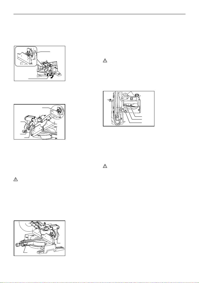
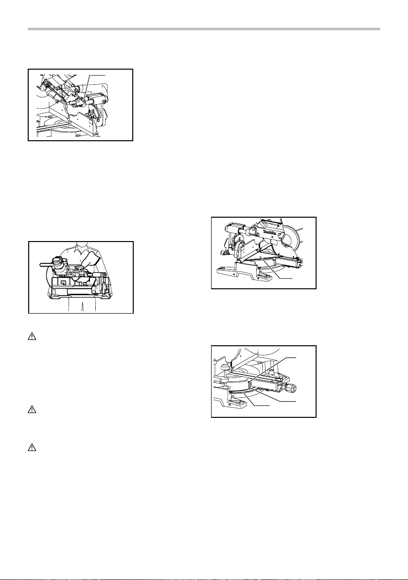
Blade guard
1. Blade guard
009605
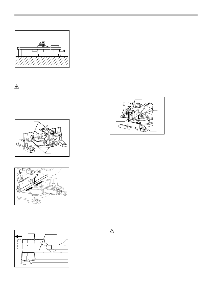
INSTALLATION
Bench mounting
When the tool is shipped, the handle is locked in the
lowered position by the stopper pin. Release the stopper
pin by lowering the handle slightly and pulling the
stopper pin.
1
009483
This tool should be bolted with four bolts to a level and
stable surface using the bolt holes provided in the tool's
base. This will help prevent tipping and possible injury.
1
009484
1. Stopper pin
1. Hex bolt
1
009485
When lowering the handle, the blade guard rises
automatically. The blade guard returns to its original
position when the cut is completed and the handle is
raised. NEVER DEFEAT OR REMOVE THE BLADE
GUARD OR THE SPRING WHICH ATTACHES TO THE
GUARD.
In the interest of your personal safety, always maintain
the blade guard in good condition. Any irregular
operation of the blade guard should be corrected
immediately. Check to assure spring loaded return
action of guard. NEVER USE THE TOOL IF THE
BLADE GUARD OR SPRING ARE DAMAGED, FAULTY
OR REMOVED. DOING SO IS HIGHLY DANGEROUS
AND CAN CAUSE SERIOUS PERSONAL INJURY.
If the see-through blade guard becomes dirty, or
sawdust adheres to it in such a way that the blade
and/or workpiece is no longer easily visible, unplug the
saw and clean the guard carefully with a damp cloth. Do
not use solvents or any petroleum-based cleaners on
the plastic guard.
If the blade guard is especially dirty and vision through
the guard is impaired, use the supplied socket wrench to
loosen the hex bolt holding the center cover. Loosen the
hex bolt by turning it counterclockwise and raise the
blade guard and center cover. With the blade guard so
positioned, cleaning can be more completely and
efficiently accomplished. When cleaning is complete,
reverse procedure above and secure bolt. Do not
remove spring holding blade guard. If guard becomes
discolored through age or UV light exposure, contact a
Makita service center for a new guard. DO NOT
DEFEAT OR REMOVE GUARD.
6
Page 7
1. Blade guard
1
009486
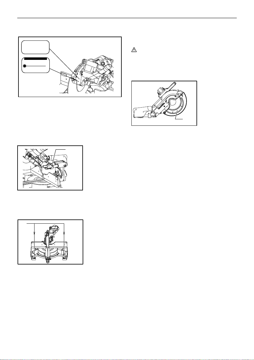
Positioning kerf board
1. Kerf board
1
009488
1
3
4
5
6
001538
This tool is provided with the kerf boards in the turn base
to minimize tearing on the exit side of a cut. The kerf
boards are factory adjusted so that the saw blade does
not contact the kerf boards. Before use, adjust the kerf
boards as follows:
1. Saw blade
2
2. Blade teeth
3. Kerf board
4. Left bevel cut
5. Straight cut
6. Right bevel cut
1. Lock lever
2. Screw
2
009496
First, unplug the tool. Loosen all the screws (2 each on
left and right) securing the kerf boards. Re-tighten them
only to the extent that the kerf boards can still be easily
moved by hand. Lower the handle fully and push in the
stopper pin to lock the handle in the lowered position.
Loosen the locking screw counterclockwise which
secures the upper slide poles and also push forward the
lock lever which secures the lower slide poles. Pull the
carriage toward you fully. Adjust the kerf boards so that
the kerf boards just contact the sides of the blade teeth.
Tighten the front screws (do not tighten firmly). Push the
carriage toward the guide fence fully and adjust the kerf
boards so that the kerf boards just contact the sides of
blade teeth. Tighten the rear screws (do not tighten
firmly).
After adjusting the kerf boards, release the stopper pin
and raise the handle. Then tighten all the screws
securely.
1
CAUTION:
• Before and after changing the bevel angle, always
adjust the kerf boards as described above.
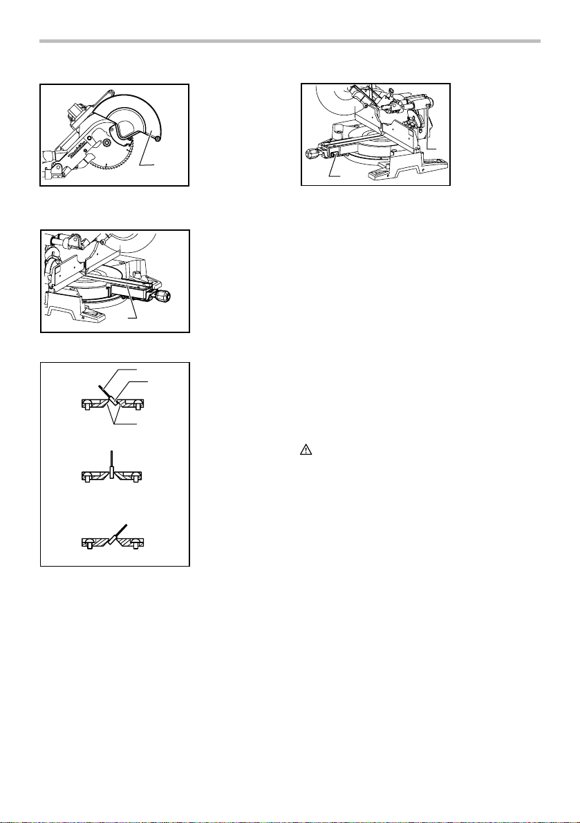
Maintaining maximum cutting capacity
Unplug the tool before any adjustment is attempted. This
tool is factory adjusted to provide the maximum cutting
capacity for a 255 mm (10") saw blade.
When installing a new blade, always check the lower
limit position of the blade and if necessary, adjust it as
follows:
7
Page 8
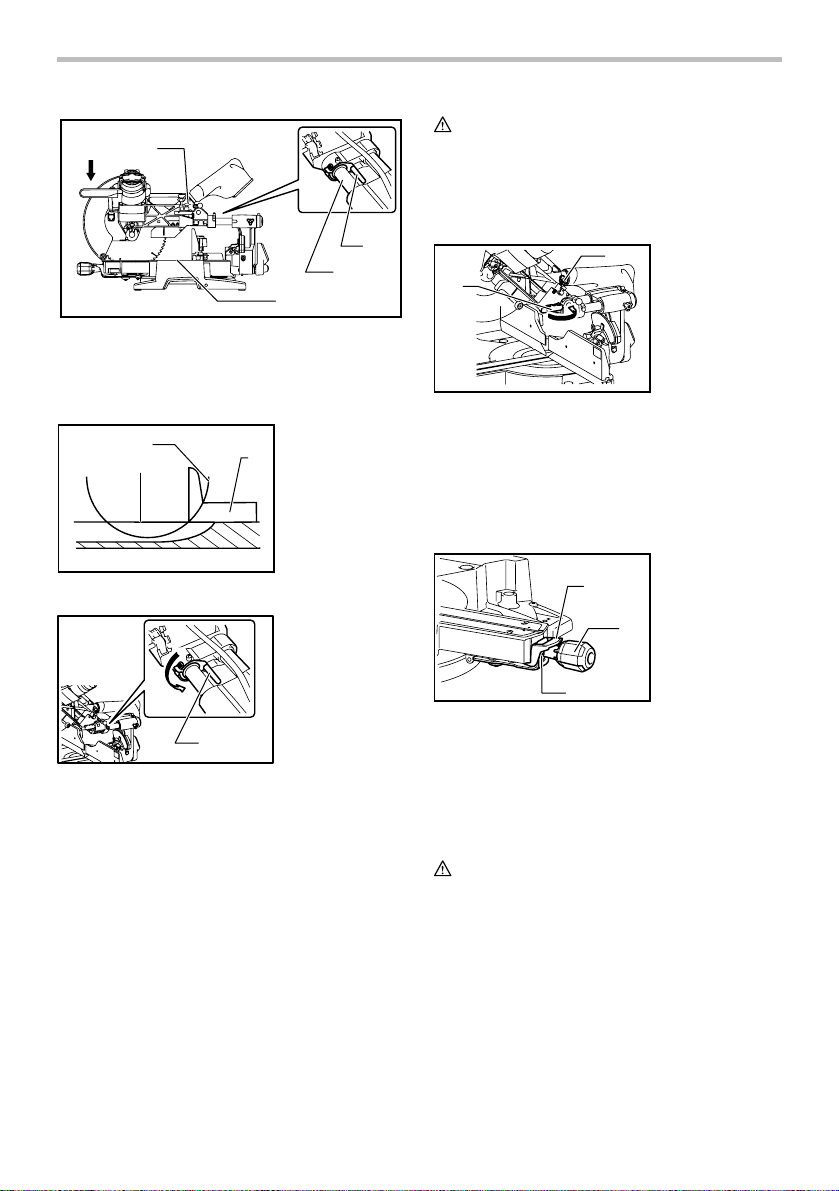
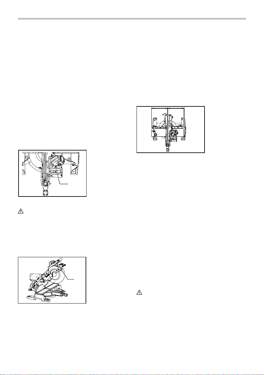
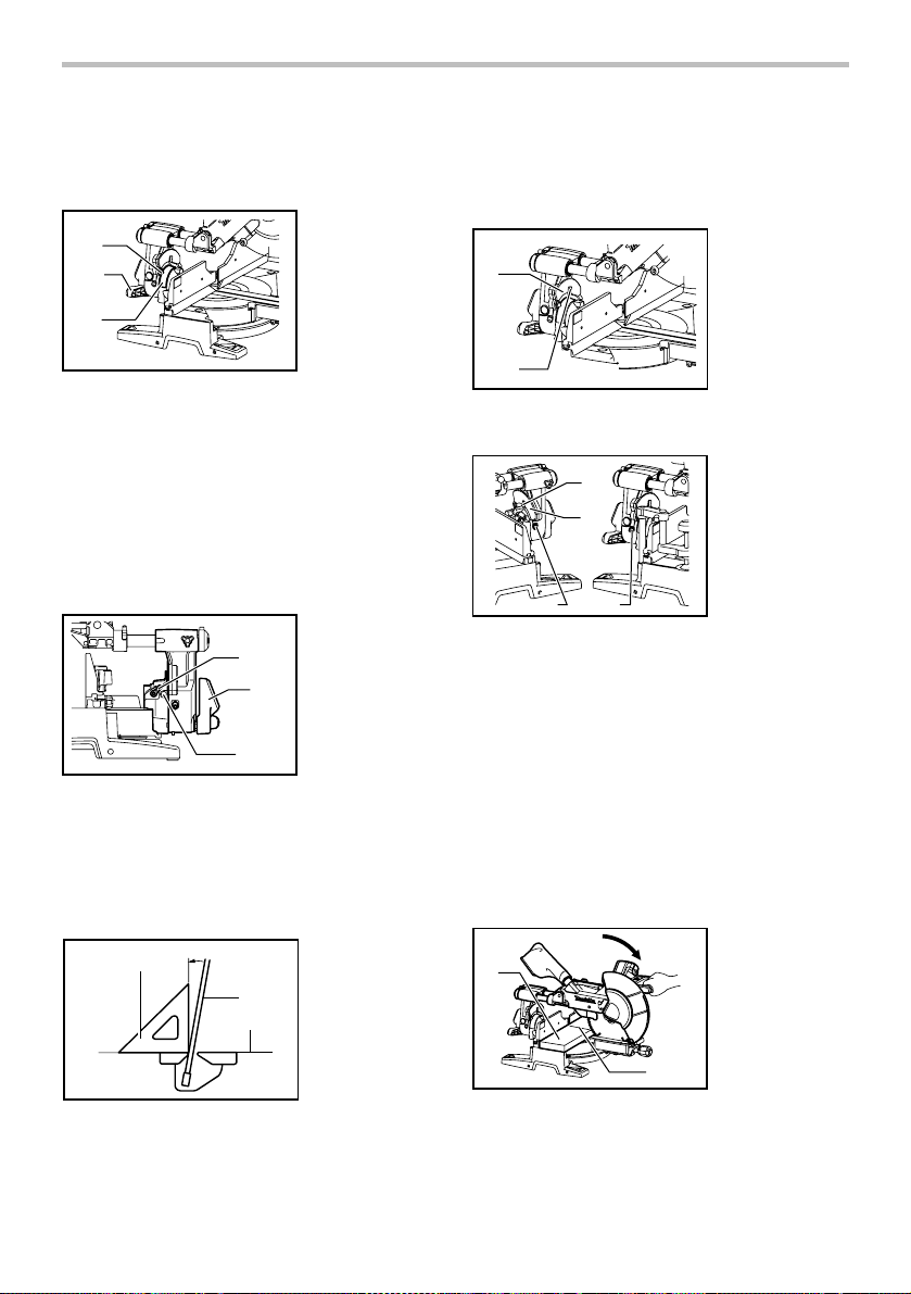
1. Adjusting bolt
2. Turn base
3. Stopper lever
4. Slide pipe
009518
2
1
009737
CAUTION:
1
• After installing a new blade, always be sure that
the blade does not contact any part of the lower
base when the handle is lowered completely.
Always do this with the tool unplugged.
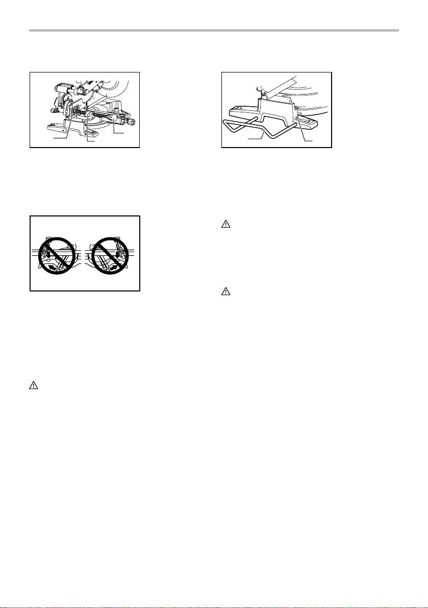
Stopper arm
2
1. Top surface of
turn base
3
2. Periphery of
blade
3. Guide fence
3
4
1
009487
The lower limit position of the blade can be easily
adjusted with the stopper arm. To adjust it, rotate the
stopper arm in the direction of the arrow as shown in the
figure. Adjust the adjusting screw so that the blade stops
at the desired position when lowering the handle fully.
1. Stopper arm
2
2. Adjusting screw
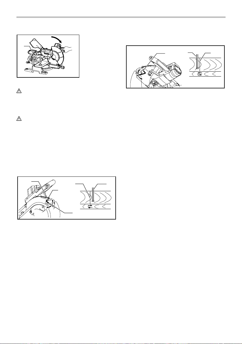
Adjusting the miter angle
2
1. Lock lever
2. Grip
3. Cam
1
1. Stopper lever
1
009736
First, unplug the tool. Lower the stopper lever to position
the saw blade as shown in the figure. Push the carriage
toward the guide fence fully and lower the handle
completely. Use the socket wrench to turn the adjusting
bolt until the periphery of the blade extends slightly
below the top surface of the turn base at the point where
the front face of the guide fence meets the top surface of
the turn base.
With the tool unplugged, rotate the blade by hand while
holding the handle all the way down to be sure that the
blade does not contact any part of the lower base.
Re-adjust slightly, if necessary.
After adjustment, always return the stopper lever to the
original position by turning it counterclockwise.
009517
3
Push the grip so that the cams engages and turn it
clockwise until it stops. Turn the turn base while pressing
down the lock lever. When you have moved the grip to
the position where the pointer points to the desired angle
on the miter scale, turn the grip to 90° counterclockwise
to lock the turn base.
CAUTION:
• When turning the turn base, be sure to raise the
handle fully.
• After changing the miter angle, always secure the
turn base by turning the grip to 90°
counterclockwise.
Adjusting the bevel angle
To adjust the bevel angle, loosen the lever at the rear of
the tool counterclockwise. Push the latch lever forward
fully and unlock the arm by pushing the handle slightly in
the direction that you intend to tilt the saw blade.
8
Page 9
When tilting the carriage to the right, tilt the carriage to
the left slightly after loosening the lever and press the
releasing button. With the releasing button being
pressed, tilt the carriage to the right.
2
1
009489
1. Lever
2. Latch lever
Tilt the saw blade until the pointer points to the desired
angle on the bevel scale. Then tighten the lever
clockwise firmly to secure the arm.
1. Scale plate
2. Release button
3. Pointer
4. Latch lever
3
009513
4
2
1
When the latch lever is pulled toward yourself, the saw
blade can be locked using positive stops at the right and
left 22.5 ° and 33.9 ° angle to the base surface.
When the latch lever is pushed forward to the arm holder,
the saw blade can be locked at an desired angle within
the specified bevel angle range.
CAUTION:
• When tilting the saw blade, be sure to raise the
handle fully.
• After changing the bevel angle, always secure the
arm by tightening the lever clockwise.
• When changing bevel angles, be sure to position
the kerf boards appropriately as explained in the
"Positioning kerf boards" section.
Slide lock adjustment
1. Lock lever
2. Screw
2
009496
1
To lock the lower slide pole, pull the lock lever toward
yourself.
To lock the upper slide pole, turn the locking screw
clockwise.
Switch action
CAUTION:
• Before plugging in the tool, always check to see
that the switch trigger actuates properly and
returns to the "OFF" position when released.
• Do not pull the switch trigger hard without pressing
in the lock-off button. This can cause switch
breakage.
1. Switch trigger
2. Lock-off button
3. Hole for padlock
1
3
2
009491
To prevent the switch trigger from being accidentally
pulled, a lock-off button is provided. To start the tool,
press in the lock-off button and pull the switch trigger.
Release the switch trigger to stop.
A hole is provided in the switch trigger for insertion of
padlock to lock the tool off.
WARNING:
• Do not use a lock with a shank or cable any
smaller than 6.35 mm (1/4") in diameter.
• NEVER use tool without a fully operative switch
trigger. Any tool with an inoperative switch is
HIGHLY DANGEROUS and must be repaired
before further usage.
• For your safety, this tool is equipped with a lock-off
button which prevents the tool from unintended
starting. NEVER use the tool if it runs when you
simply pull the switch trigger without pressing the
lock-off button. Return tool to a Makita service
center for proper repairs BEFORE further usage.
• NEVER tape down or defeat purpose and function
of lock-off button.
Electric brake
This tool is equipped with an electric blade brake. If the
tool consistently fails to quickly stop blade after switch
trigger release, have tool serviced at a Makita service
center.
9
Page 10
The blade brake system is not a substitute for blade
guard. NEVER USE TOOL WITHOUT A FUNCTIONING
BLADE GUARD. SERIOUS PERSONAL INJURY CAN
RESULT.
Electronic function
Constant speed control
• Possible to get fine finish, because the rotating
speed is kept constantly even under the loaded
condition.
• Additionally, when the load on the tool exceeds
admissible levels, power to the motor is reduced to
protect the motor from overheating. When the load
returns to admissible levels, the tool will operate as
normal.
Soft start feature
• Soft start because of suppressed starting shock.
Laser beam action
For model LS1016L only
1. Switch for laser
1
009492
CAUTION:
• LASER RADIATION
Do not stare into beam.
To turn on the laser beam, press the upper position (I) of
the switch. Press the lower position (O) to turn off.
Laser line can be shifted to either the left or right side of
the saw blade by adjusting the adjusting screw as
follows.
009493
1. Loosen the adjusting screw by turning it
counterclockwise.
2. With the adjusting screw loosened, slide the
adjusting screw to the right or left as far as it goes.
1. Adjusting screw
1
3. Tighten the adjusting screw firmly at the position
where it stops sliding.
Laser line is factory adjusted so that it is positioned
within 1 mm (0.04") from the side surface of the blade
(cutting position).
NOTE:
• When laser line is dim and almost or entirely
invisible because of the direct sunlight in the indoor
or outdoor window-by work, relocate the work area
to a place not exposed to the direct sunlight.
Aligning the laser line
AB
009494
Laser line can be shifted to either the left or right side of
the blade according to the applications of cutting. Refer
to explanation titled "Laser beam action" regarding its
shifting method.
NOTE:
• Use wood facing against the guide fence when
aligning the cutting line with the laser line at the
side of guide fence in compound cutting (bevel
angle 45 degrees and miter angle right 45
degrees).
A) When you obtain correct size on the left side of
workpiece
• Shift the laser line to the left of the blade.
B) When you obtain correct size on the right side of
workpiece
• Shift the laser line to the right of the blade.
Align the cutting line on your workpiece with the laser
line.
ASSEMBLY
CAUTION:
• Always be sure that the tool is switched off and
unplugged before carrying out any work on the
tool.
10
Page 11
Socket wrench storage
1
009495
The socket wrench is stored as shown in the figure.
When using the socket wrench, pull it out of the wrench
holder. After using the socket wrench, return it to the
wrench holder.
Installing or removing saw blade
CAUTION:
• Always be sure that the tool is switched off and
unplugged before installing or removing the blade.
• Use only the Makita socket wrench provided to
install or remove the blade. Failure to do so may
result in overtightening or insufficient tightening of
the hex bolt. This could cause an injury.
Lock the handle in the raised position by pushing in the
stopper pin.
1
009483
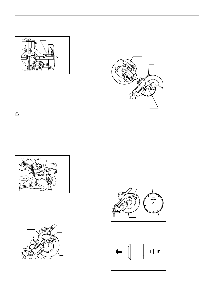
To remove the blade, use the socket wrench to loosen
the hex bolt holding the center cover by turning it
counterclockwise. Raise the blade guard and center
cover.
1
2
009497
1. Wrench holder
2. Socket wrench
2
1. Stopper pin
1. Center cover
2. Socket wrench
3
3. Hex bolt
4. Blade guard
4
Press the shaft lock to lock the spindle and use the
socket wrench to loosen the hex bolt clockwise. Then
remove the hex bolt, outer flange and blade.
1. Shaft lock
2. Blade case
1
3
009498
NOTE:
• When inner flange is removed mistakenly, be sure
to install it on the spindle with its protrusion facing
the spindle.
To install the blade, mount it carefully onto the spindle,
making sure that the direction of the arrow on the
surface of the blade matches the direction of the arrow
on the blade case.
Install the outer flange and hex bolt, and then use the
socket wrench to tighten the hex bolt (left-handed)
securely counterclockwise while pressing the shaft lock.
1
34
009500
1
009499
2
3
4
3. Hex bolt
2
1. Arrow
2
2. Arrow
3. Blade case
4. Saw blade
1. Hex bolt
2. Outer flange
3. Saw blade
4. Inner flange
5. Spindle
5
11
Page 12
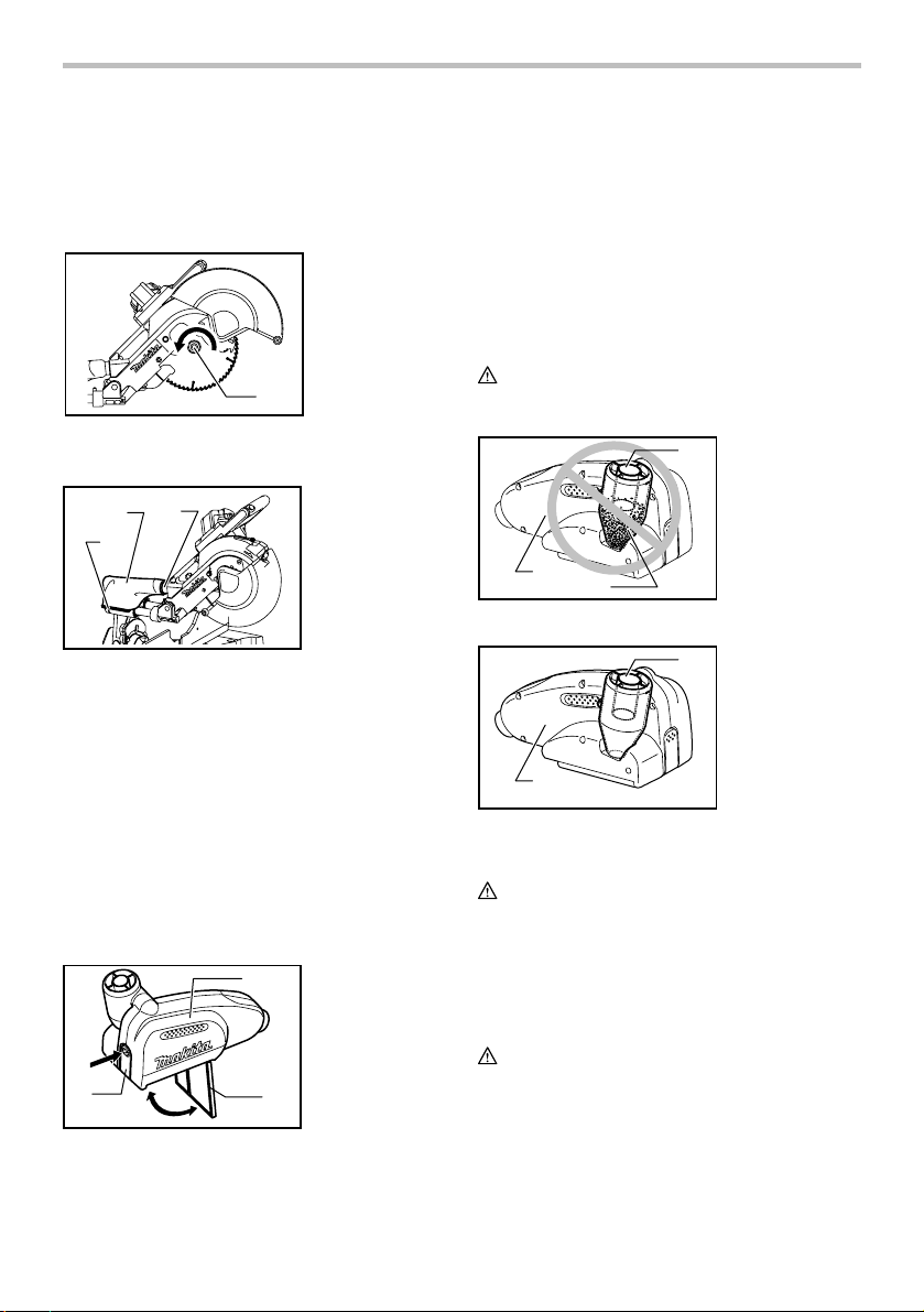
Return the blade guard and center cover to its original
position. Then tighten the hex bolt clockwise to secure
the center cover. Release the handle from the raised
position by pulling the stopper pin. Lower the handle to
make sure that the blade guard moves properly. Make
sure shaft lock has released spindle before making cut.
1. Hex bolt
1
009524
Dust bag
3
2
1
009501
The use of the dust bag makes cutting operations clean
and dust collection easy. To attach the dust bag, fit it
onto the dust nozzle.
When the dust bag is about half full, remove the dust
bag from the tool and pull the fastener out. Empty the
dust bag of its contents, tapping it lightly so as to remove
particles adhering to the insides which might hamper
further collection.
NOTE:
If you connect a vacuum cleaner to your saw, more
efficient and cleaner operations can be performed.
1. Fastener
2. Dust bag
3. Dust nozzle
Dust box (Optional accessory)
1
3
006793
1. Dust box
2. Cover
3. Button
2
Insert the dust box into the dust nozzle.
Empty the dust box at the earliest possible.
To empty the dust box, open the cover by pushing the
button and throw away sawdust. Return the cover to the
original position and it locks. Dust box can easily be
removed by pulling out while turning it near the dust
nozzle on the tool.
NOTE:
• If you connect a Makita vacuum cleaner to this tool,
more efficient and cleaner operations can be
performed.
CAUTION:
• Empty the dust box before collected sawdust level
reaches the cylinder part.
1. Cylinder part
1
2. Dust box
3. Sawdust
2
006792
3
1. Cylinder part
1
2. Dust box
2
006794
Securing workpiece
WARNING:
• It is extremely important to always secure the
workpiece properly and tightly with the vise. Failure
to do so can cause the tool to be damaged and/or
the workpiece to be destroyed. PERSONAL
INJURY MAY ALSO RESULT. Also, after a cutting
operation, DO NOT raise the blade until the blade
has come to a complete stop.
CAUTION:
• When cutting long workpieces, use supports that
are as high as the top surface level of the turn base.
Do not rely solely on the vertical vise and/or
horizontal vise to secure the workpiece.
Thin material tends to sag. Support workpiece over
its entire length to avoid blade pinch and possible
KICKBACK.
12
Page 13
1
001549
2
1. Support
2. Turn base
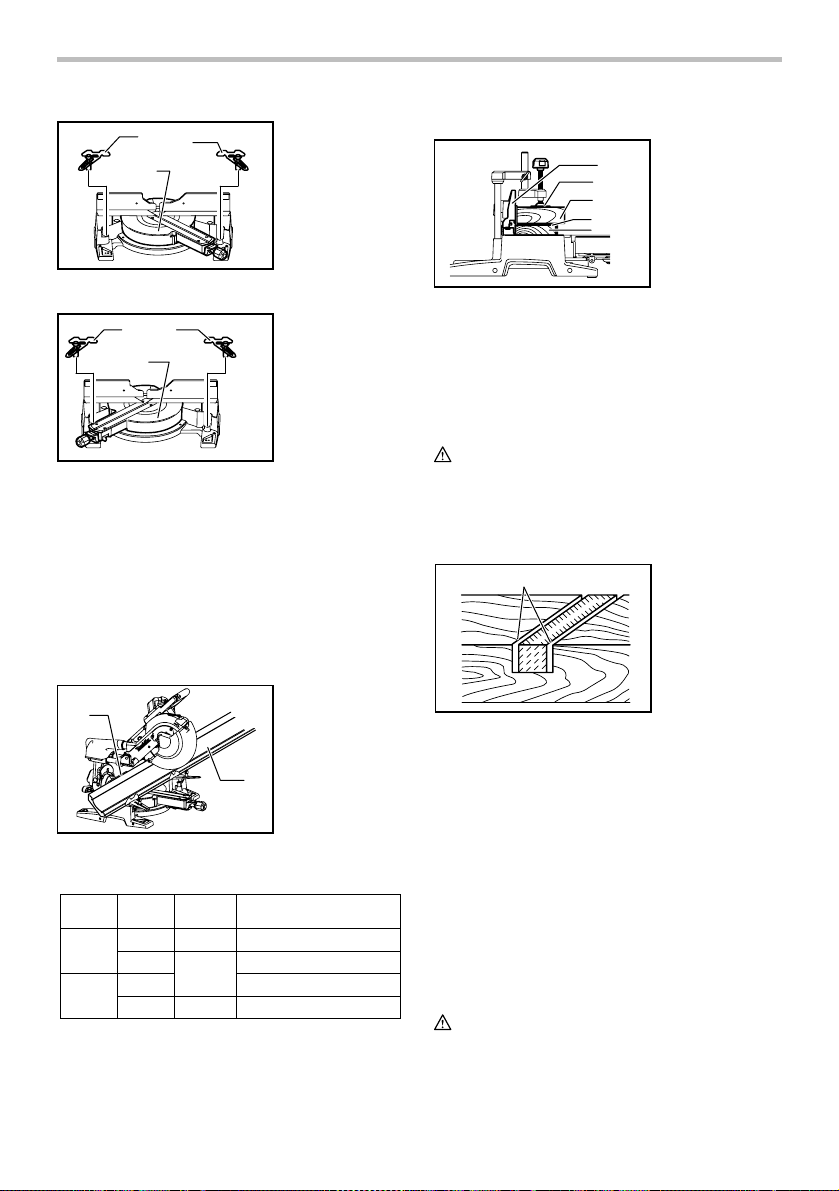
Fence adjustment
WARNING:
• Before operating the tool, make sure that the upper
and lower fences are secured firmly.
• Before bevel-cutting, make sure that no part of the
tool contacts the upper and lower fences when
lowering the handle fully and pulling or pushing the
carriage all the way.
1
2
009508
1. Lever
2. Clamping screw
009611
Sliding the fences to inside by loosening the clamping
screw only before miter-cutting allows support of
workpiece close to the saw blade.
1
009519
1. Upper fence
2
2. Lower fence
To adjust the fences before bevel-cutting, loosen a lever
and slide the upper fence outward. Make a dry run with
the saw turned off and check clearance.
Adjust the fence to be as close to the blade as practical
to provide maximum workpiece support, without
interfering with arm up and down movement. Tighten
lever securely. When the bevel operations are complete,
don't forget to relocate the fence.
NOTE:
• For easy tightening/loosening, the position of the
lever can be changed according to your need by
pulling it up.
Vertical vise
4
3
009502
The vertical vise can be installed in two positions on
either the left or right side of the base. Insert the vise rod
into the hole in the base.
Position the vise arm according to the thickness and
shape of the workpiece and secure the vise arm by
tightening the screw. If the screw to secure the vise arm
contacts the carriage, install the screw on the opposite
side of vise arm. Make sure that no part of the tool
contacts the vise when lowering the handle fully and
pulling or pushing the carriage all the way. If some part
contacts the vise, re-position the vise.
Press the workpiece flat against the guide fence and the
turn base. Position the workpiece at the desired cutting
position and secure it firmly by tightening the vise knob.
Turning the vise knob to 90° counterclockwise allows the
vise knob to be moved up and down, facilitating the
quick setting of workpiece. To secure the workpiece after
setting, turn it the vise knob clockwise.
CAUTION:
• The workpiece must be secured firmly against the
turn base and guide fence with the vise during all
operations.
1. Vise knob
2. Vise arm
3. Vise rod
1
4. Screw
2
13
Page 14
Horizontal vise (optional accessory)
1. Vise plate
2. Vise nut
3. Vise knob
Holders (Optional accessory)
1. Holder
2. Screw
1
009606
3
2
The horizontal vise can be installed in two positions on
either the left or right side of the base. When performing
15° or greater miter cuts, install the horizontal vise on
the side opposite the direction in which the turn base is
to be turned.
005232
By flipping the vise nut to the left, the vise is released,
and rapidly moves in and out. To grip the workpiece,
push the vise knob forward until the vise plate contacts
the workpiece and flip the vise nut to the right. Then turn
the vise knob clockwise to secure the workpiece.
The maximum width of workpiece which can be secured
by the horizontal vise is 215 mm (8-1/2").
CAUTION:
• Always rotate the vise nut to the right fully when
securing the workpiece. Failure to do so may result
in insufficient securing of the workpiece. This could
cause the workpiece to be thrown, cause damage
to the blade or cause the loss of control, which can
result in PERSONAL INJURY.
• When cutting out thin workpiece, such as base
boards, against the fence, always use the
horizontal vise.
1
009607
2
The holders can be installed on either side as a
convenient means of holding workpieces horizontally.
Slip the holder rods into the holes in the base and adjust
their length according to the workpiece to be held. Then
tighten the holders securely with the screws.
CAUTION:
• Always support long workpieces level with the top
surface of the turn base for accurate cuts and to
prevent dangerous loss of control of the tool.
OPERATION
CAUTION:
• Before use, be sure to release the handle from the
lowered position by pulling the stopper pin.
• Make sure the blade is not contacting the
workpiece, etc. before the switch is turned on.
• Do not apply excessive pressure on the handle
when cutting. Too much force may result in
overload of the motor and/or decreased cutting
efficiency. Push down handle with only as much
force as is necessary for smooth cutting and
without significant decrease in blade speed.
• Gently press down the handle to perform the cut. If
the handle is pressed down with force or if lateral
force is applied, the blade will vibrate and leave a
mark (saw mark) in the workpiece and the
precision of the cut will be impaired.
• During a slide cut, gently push the carriage toward
the guide fence without stopping. If the carriage
movement is stopped during the cut, a mark will be
left in the workpiece and the precision of the cut
will be impaired.
14
Page 15
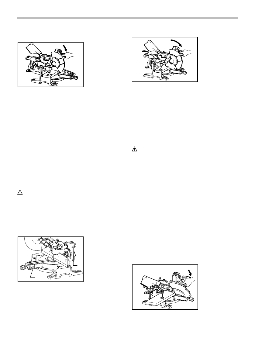
1. Press cutting (cutting small workpieces)
009503
Workpieces up to 71 mm (2-13/16") high and 155
mm (6-1/8") wide can be cut in the following way.
After turning the stopper lever clockwise and
sliding the carriage to your desired position, push
the carriage toward the guide fence fully and
tighten the locking screw clockwise and pull the
lock lever toward yourself to secure the carriage.
Secure the workpiece with the vise. Switch on the
tool without the blade making any contact and wait
until the blade attains full speed before lowering.
Then gently lower the handle to the fully lowered
position to cut the workpiece. When the cut is
completed, switch off the tool and WAIT UNTIL
THE BLADE HAS COME TO A COMPLETE STOP
before returning the blade to its fully elevated
position.
CAUTION:
• Firmly tighten the locking screw clockwise and pull
the lock lever toward yourself so that the carriage
will not move during operation. Insufficient
tightening may cause unexpected kickback of the
blade. Possible serious PERSONAL INJURY may
result.
2. Slide (push) cutting (cutting wide workpieces)
1. Lock lever
2. Screw
2
009504
Pull the carriage toward you fully. Switch on the
tool without the blade making any contact and wait
until the blade attains full speed. Press down the
handle and PUSH THE CARRIAGE TOWARD
THE GUIDE FENCE AND THROUGH THE
WORKPIECE. When the cut is completed, switch
off the tool and WAIT UNTIL THE BLADE HAS
COME TO A COMPLETE STOP before returning
the blade to its fully elevated position.
CAUTION:
• Whenever performing the slide cut, FIRST PULL
THE CARRIAGE TOWARD YOU FULLY and press
down the handle to the fully lowered position, then
PUSH THE CARRIAGE TOWARD THE GUIDE
FENCE. NEVER START THE CUT WITH THE
CARRIAGE NOT FULLY PULLED TOWARD YOU.
If you perform the slide cut without pulling the
carriage fully or if you perform the slide cut toward
your direction, the blade may kickback
unexpectedly with the potential to cause serious
PERSONAL INJURY.
• Never perform the slide cut with the handle locked
in the lowered position by pressing the stopper pin.
• Never loosen the knob which secures the carriage
while the blade is rotating. This may cause serious
injury.
3. Miter cutting
Refer to the previously covered "Adjusting the
miter angle".
4. Bevel cut
009496
1
Loosen the locking screw counterclockwise and
also push forward the lock lever so that the
carriage can slide freely. Secure the workpiece
with the vise.
15
009505
Page 16
Loosen the lever and tilt the saw blade to set the
bevel angle (Refer to the previously covered
"Adjusting the bevel angle"). Be sure to retighten
the lever firmly to secure the selected bevel angle
safely. Secure the workpiece with a vise. Make
sure the carriage is pulled all the way back toward
the operator. Switch on the tool without the blade
making any contact and wait until the blade attains
full speed. Then gently lower the handle to the fully
lowered position while applying pressure in parallel
with the blade and PUSH THE CARRIAGE
TOWARD THE GUIDE FENCE TO CUT THE
WORKPIECE. When the cut is completed, switch
off the tool and WAIT UNTIL THE BLADE HAS
COME TO A COMPLETE STOP before returning
the blade to its fully elevated position.
CAUTION:
• Always be sure that the blade will move down to
bevel direction during a bevel cut. Keep hands out
of path of saw blade.
• During a bevel cut, it may create a condition
whereby the piece cut off will come to rest against
the side of the blade. If the blade is raised while the
blade is still rotating, this piece may be caught by
the blade, causing fragments to be scattered which
is dangerous. The blade should be raised ONLY
after the blade has come to a complete stop.
• When pressing down the handle, apply pressure in
parallel with the blade. If a force is applied
perpendicularly to the turn base or if the pressure
direction is changed during a cut, the precision of
the cut will be impaired.
• Always slide or remove the upper fence so that it
does not interfere any part of the carriage when
performing bevel cuts.
5. Compound cutting
Compound cutting is the process in which a bevel
angle is made at the same time in which a miter
angle is being cut on a workpiece. Compound
cutting can be performed at angle shown in the
table.
Miter angle Bevel angle
Left and Right 0 - 45
009713
Left and Right 0 - 45
When performing compound cutting, refer to
"Press cutting", "Slide cutting", "Miter cutting" and
"Bevel cut" explanations.
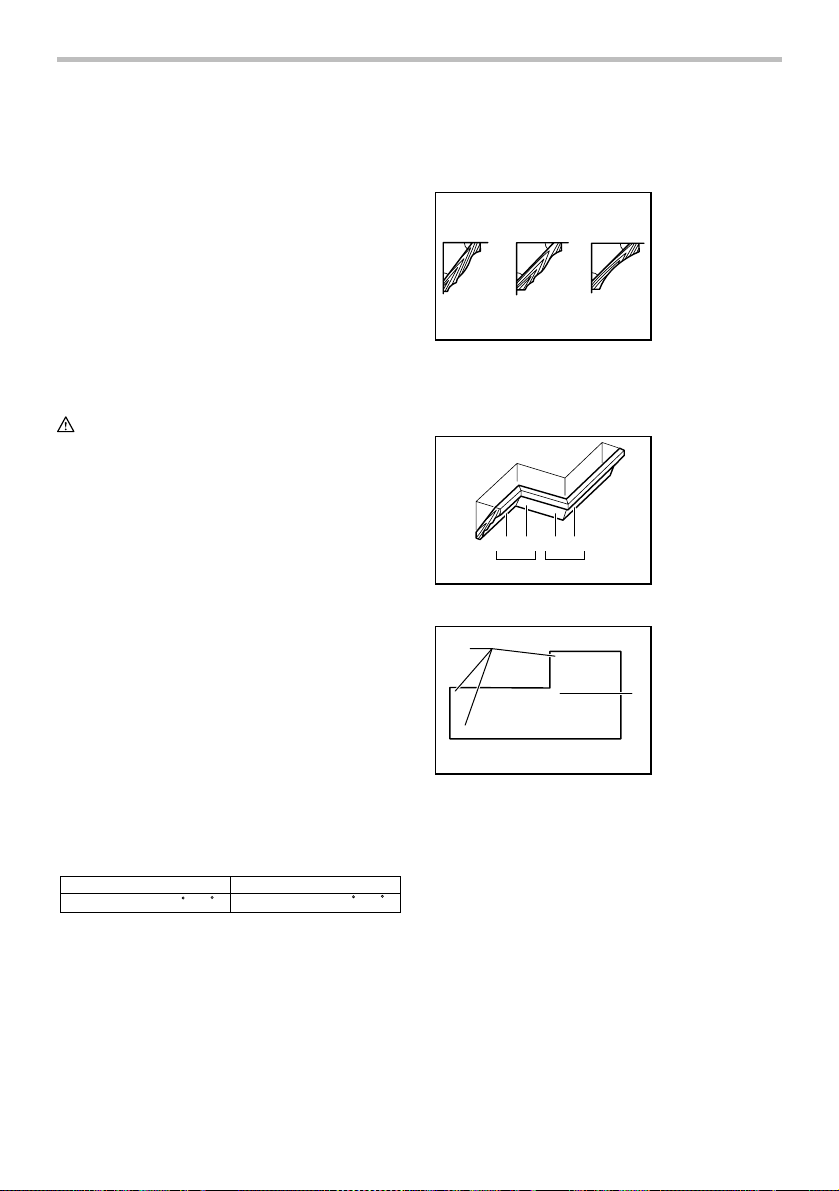
6. Cutting crown and cove moldings
Crown and cove moldings can be cut on a
compound miter saw with the moldings laid flat on
the turn base.
There are two common types of crown moldings
and one type of cove moldings; 52/38° wall angle
crown molding, 45° wall angle crown molding and
45° wall angle cove molding. See illustrations.
52
38
45
45
123
001555
There are crown and cove molding joints which are
made to fit "Inside" 90° corners ((1) and (2) in Fig.
A) and "Outside" 90° corners ((3) and (4) in Fig. A).
(1) (2) (3)(4)
Fig.A
001556
1 2
(1)
(2)
001557
1
(2)
(1)
(1)
(4)
(3)
Measuring
Measure the wall length and adjust workpiece on
table to cut wall contact edge to desired length.
Always make sure that cut workpiece length at the
back of the workpiece is the same as wall length.
Adjust cut length for angle of cut. Always use
several pieces for test cuts to check the saw
angles.
When cutting crown and cove moldings, set the
bevel angle and miter angle as indicated in the
table (A) and position the moldings on the top
surface of the saw base as indicated in the table
(B).
1. 52/38 ゚ type
crown molding
2. 45 ゚ type crown
45
45
molding
3. 45 ゚ type cove
molding
1. Inside corner
2. Outside corner
1. Inside corner
(2)
2. Outside corner
(1)
(2)
2
(1)
(2)
16
Page 17
In the case of left bevel cut
Table (A)
Bevel angleMiter angle
52/38° type 45° type
Left 33.9° Left 30°
For inside
corner
For outside
corner
006361
Molding
position in
Fig. A
(1)
(2)
(3)
(4)
Table (B)
Molding
Molding edge against
position in
guide fence
Fig. A
Ceiling contact edge should
(1)
For inside
corner
For
outside
corner
006362
be against guide fence.
(2)
Wall contact edge should be
against guide fen
(3)
Ceiling contact edge should
(4)
be against guide fence.
Example:
In the case of cutting 52/38° type crown
molding for position (1) in Fig. A:
• Tilt and secure bevel angle setting to
33.9° LEFT.
• Adjust and secure miter angle setting to
31.6° RIGHT.
• Lay crown molding with its broad back
(hidden) surface down on the turn base
with its CEILING CONTACT EDGE
against the guide fence on the saw.
• The finished piece to be used will
always be on the LEFT side of the blade
after the cut has been made.
In the case of right bevel cut
Table (A)
Bevel angleMiter angle
52/38° type 45° type
Right 33.9° Right 30°
For inside
corner
For outside
corner
006363
Molding
position in
Fig. A
(1)
(2)
(3)
(4)
52/38° type
Right 31.6°
Left 31.6°Left 35.3°
ce.
52/38° type
Right 31.6°
Left 31.6°Left 35.3°
45° type
Right 35.3°
Right 35.3°Right 31.6°
Finished piece
Finished piece
will be on the
Left side of
blade.
Finished piece
will be on the
Right side of
blade.
45° type
Right 35.3°
Right 35.3°Right 31.6°
Table (B)
Molding
Molding edge against
position in
guide fence
Fig. A
Wall contact edge should b
(1)
For inside
corner
For
outside
corner
006364
against guide fence.
(2)
Ceiling contact edge should
be against guide fence.
(3)
Wall contact edge should be
(4)
against guide fence.
Finished piece
e
Finished piece
will be on the
Right side of
blade.
Finished piece
will be on the
Left side of
blade.
Example:
In the case of cutting 52/38° type crown
molding for position (1) in Fig. A:
• Tilt and secure bevel angle setting to
33.9° RIGHT.
• Adjust and secure miter angle setting to
31.6° RIGHT.
• Lay crown molding with its broad back
(hidden) surface down on the turn base
with its WALL CONTACT EDGE against
the guide fence on the saw.
• The finished piece to be used will
always be on the RIGHT side of the
blade after the cut has been made.
17
Page 18
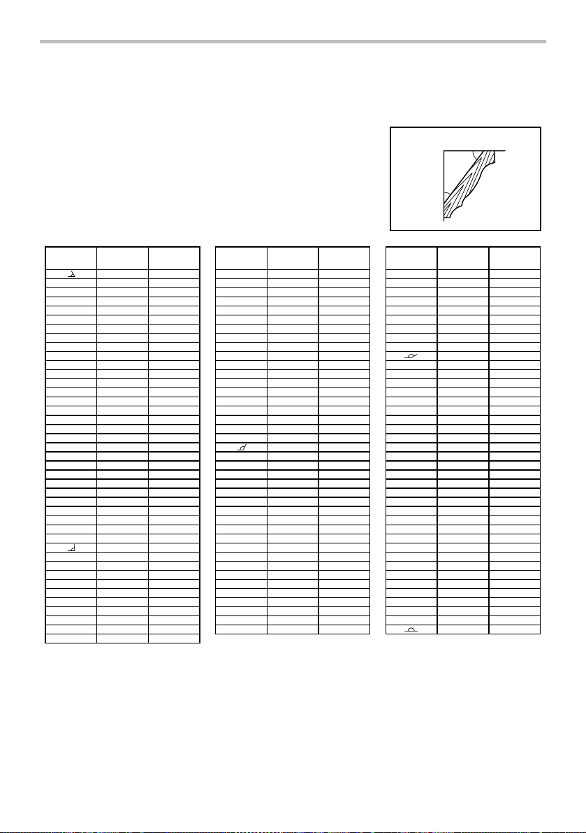
Compound Miter Saw
Miter and Bevel Angle Settings
Ceiling
52°
38°
Wall
Wall to Crown Molding Angle: 52/38 degrees
Wall Angle
(deg.)
EN0002-1
Bevel Angle
60
61
62
63
64
65
66
67
68
69
70
71
72
73
74
75
76
77
78
79
80
81
82
83
84
85
86
87
88
89
90
91
92
93
94
95
96
97
98
99
100
(deg.)
43.0
42.8
42.5
42.2
41.9
41.7
41.4
41.1
40.8
40.5
40.2
39.9
39.6
39.3
39.0
38.7
38.4
38.1
37.8
37.4
37.1
36.8
36.5
36.2
35.8
35.5
35.2
34.9
34.5
34.2
33.9
33.5
33.2
32.8
32.5
32.2
31.8
31.5
31.1
30.8
30.4
Miter Angle
(deg.)
46.8
46.3
45.7
45.1
44.6
44.0
43.5
42.9
42.4
41.9
41.3
40.8
40.3
39.8
39.2
38.7
38.2
37.7
37.2
36.8
36.3
35.8
35.3
34.8
34.4
33.9
33.4
33.0
32.5
32.1
.6
31
31.2
30.7
30.3
29.9
29.4
29.0
28.6
28.2
27.7
27.3
Wall Angle
(deg.)
Bevel Angle
101
102
103
104
105
106
107
108
109
110
111
112
113
114
115
116
117
118
119
120
121
122
123
124
125
126
127
128
129
130
131
132
133
134
135
136
137
138
139
140
(deg.)
30.1
29.7
29.4
29.0
28.7
28.3
28.0
27.6
27.2
26.9
26.5
26.1
25.8
25.4
25.0
24.7
24.3
23.9
23.6
23.2
22.8
22.5
22.1
21.7
21.3
21.0
20.6
20.2
19.8
19.5
19.1
18.7
18.3
17.9
17.6
17.2
16.8
16.4
16.0
15.6
Miter Angle
(deg.)
26.9
26.5
26.1
25.7
25.3
24.9
24.5
24.1
23.7
23.3
22.9
22.6
22.2
21.8
21.4
21.0
20.7
20.3
19.9
19.6
19.2
18.8
18.5
18.1
17.8
17.4
17.1
.7
16
16.4
16.0
15.7
15.3
15.0
14.6
14.3
14.0
13.6
13.3
13.0
12.8
000031
Wall Angle
(deg.)
141
142
143
144
1
146
147
148
149
150
151
152
153
154
155
156
157
158
159
160
161
162
163
164
165
166
167
168
169
170
171
172
173
174
175
176
177
178
179
180
Bevel Angle
(deg.)
45
15.3
14.9
14.5
14.1
13.7
13.3
12.9
12.5
12.2
11.8
11.4
11.0
10.8
10.2
9.8
9.4
9.0
8.6
8.3
7.9
7.5
7.1
6.7
6.3
5.9
5.5
5.1
4.7
4.3
3.9
3.5
3.2
2.8
2.4
2.0
1.6
1.2
0.8
0.4
0.0
Miter Angle
(deg.)
12.3
12.0
11.6
11.3
11.0
10.7
10.3
10.0
9.7
9.4
9.0
8.7
8.4
8.1
7.8
7.5
7.1
6.8
6.5
6.2
5.9
5.6
5.3
4.9
4.6
4.3
4.0
3.7
3.4
3.1
2.8
2.5
2.2
1.8
1.5
1.2
0.9
0.6
0.3
0.0
18
Page 19
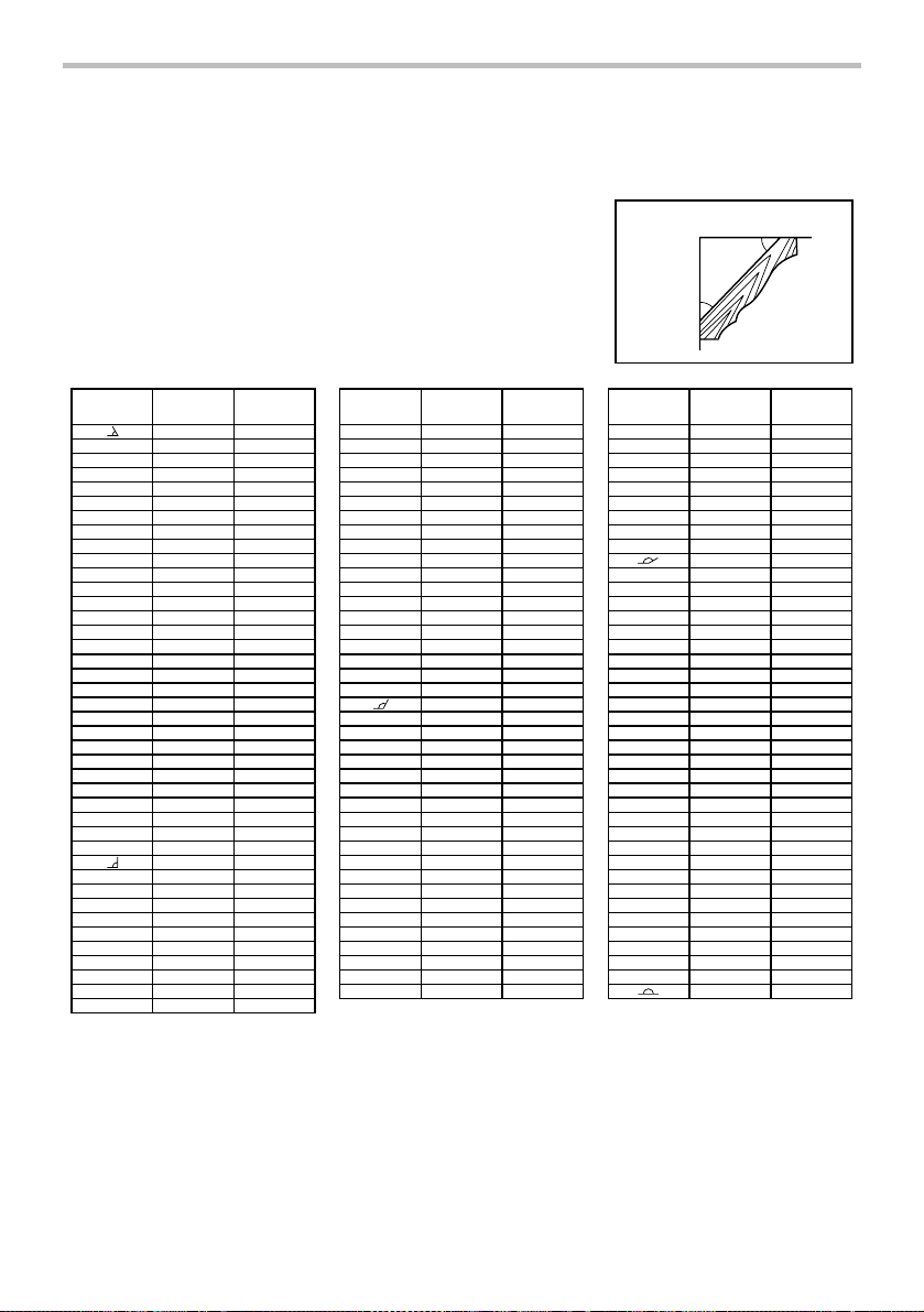
Compound Miter Saw
Miter and Bevel Angle Settings
Ceiling
45°
45°
Wall
Wall to Crown Molding Angle: 45 degrees
Wall Angle
EN0003-1
(deg.)
Bevel Angle
60
61
62
63
64
65
66
67
68
69
70
71
72
73
74
75
76
77
78
79
80
81
82
83
84
85
86
87
88
89
90
91
92
93
94
95
96
97
98
99
100
(deg.)
37.8
37.5
37.3
37.1
36.8
36.6
36.4
36.1
35.9
35.6
35.4
35.1
34.9
34.6
34.4
34.1
33.9
33.6
33.3
33.1
32.8
32.5
32.3
32.0
31.7
31.4
31.1
30.9
30.6
30.3
30.0
29.7
29.4
29.1
28.8
28.5
28.2
27.9
27.6
27.3
27.0
Miter Angle
(deg.)
50.8
50.2
49.6
49.1
48.5
48.0
47.4
46.9
46.4
45.8
45.3
44.8
44.2
43.7
43.2
42.7
42.1
41.6
41.1
40.6
40.1
39.6
39.1
38.6
38.1
37.7
37.2
36.7
36.2
35.7
35.3
34.8
34.3
33.9
33.4
32.9
32.5
32.0
31.6
31.1
30.7
Wall Angle
(deg.)
Crown molding stoppers (optional accessories)
allow easier cuts of crown molding without tilting
the saw blade. Install them on the base as shown
in the figures.
Bevel Angle
101
102
103
104
105
106
107
108
109
110
111
112
113
114
115
116
117
118
119
120
121
122
123
124
125
126
127
128
129
130
131
132
133
134
135
136
137
138
139
140
(deg.)
26.7
26.4
26.1
25.8
25.5
25.2
24.9
24.6
24.2
23.9
23.6
23.3
23.0
22.7
22.3
22.0
21.7
21.4
21.0
20.7
20.4
20.0
19.7
19.4
19.1
18.7
18.4
18.1
17.7
17.4
17.1
16.7
16.4
16.0
15.7
15.4
15.0
14.7
14.3
14.0
Miter Angle
(deg.)
30.2
9.8
2
29.4
28.9
28.5
28.1
27.6
27.2
26.8
26.3
25.9
25.5
25.1
24.7
24.3
23.8
23.4
23.0
22.6
22.2
21.8
21.4
21.0
20.6
20.2
19.8
19.4
19.0
18.6
18.2
17.9
17.5
17.1
16.7
16.3
15.9
15.6
15.2
14.8
14.4
000032
Wall Angle
(deg.)
141
142
143
144
145
146
147
148
149
150
151
152
153
154
155
156
157
158
159
160
161
162
163
164
165
166
167
168
169
170
171
172
173
174
175
176
177
178
179
180
Bevel Angle
(deg.)
13.7
13.3
13.0
12.6
12.3
11.9
11.6
11.2
10.9
10.5
10.2
9.8
9.5
9.2
8.8
8.5
8.1
7.8
7.4
7.1
6.7
6.4
6.0
5.6
5.3
4.9
4.6
4.2
3.9
3.5
3.2
2.8
2.5
2.1
1.8
1.4
1.1
0.7
0.4
0.0
Miter Angle
(deg.)
14.1
13.7
13.3
12.9
12.6
12.2
11.8
11.5
.1
11
10.7
10.4
10.0
9.6
9.3
8.9
8.5
8.2
7.8
7.5
7.1
6.7
6.4
6.0
5.7
5.3
5.0
4.6
4.3
3.9
3.5
3.2
2.8
2.5
2.1
1.8
1.4
1.1
0.7
0.4
0.0
19
Page 20
1. Crown molding
stopper L
(Optional
accessory)
2. Crown molding
stopper R
(Optional
accessory)
3. Turn base
009521
1
2
3
1. Crown molding
stopper L
2. Crown molding
stopper R
3. Turn base
009522
2
1
3
Fig. B: At right 45° miter angle
Fig. C: At left 45° miter angle
Position crown molding with its WALL CONTACT
EDGE against the guide fence and its CEILING
CONTACT EDGE against the crown molding
stoppers as shown in the figure. Adjust the crown
molding stoppers according to the size of the
crown molding. Tighten the screws to secure the
crown molding stoppers. Refer to the table (C) for
the miter angle.
1. Guide fence
1
2. Crown molding
2
009520
Table (C)
Position in
Miter angle Finished piece
Fig. A
For inside
corner
For outside
corner
006365
(1) Right 45° Save the right side of blade
(2) Save the left side of blade
Left 45°
(3) Save the right side of blade
(4) Right 45° Save the left side
of blade
1. Cutting aluminum extrusion
1. Guide fence
2. Vise
3. Spacer block
4. Aluminum
extrusion
5. Spacer block
009523
1
2
3
4
5
When securing aluminum extrusions, use spacer
blocks or pieces of scrap as shown in the figure to
prevent deformation of the aluminum. Use a
cutting lubricant when cutting the aluminum
extrusion to prevent build-up of the aluminum
material on the blade.
CAUTION:
• Never attempt to cut thick or round aluminum
extrusions. Thick aluminum extrusions may come
loose during operation and round aluminum
extrusions cannot be secured firmly with this tool.
2. Groove cutting
1
001563
1. Cut grooves with
blade
A dado type cut can be made by proceeding as
follows:
Adjust the lower limit position of the blade using
the adjusting screw and the stopper arm to limit the
cutting depth of the blade. Refer to "Stopper arm"
section described previously.
After adjusting the lower limit position of the blade,
cut parallel grooves across the width of the
workpiece using a slide (push) cut as shown in the
figure. Then remove the workpiece material
between the grooves with a chisel. Do not attempt
to perform this type of cut using wide (thick) blades
or with a dado blade. Possible loss of control and
injury may result.
CAUTION:
• Be sure to return the stopper arm to the original
position when performing other than groove
cutting.
20
Page 21
Carrying tool
1
009483
Make sure that the tool is unplugged. Secure the blade
at 0° bevel angle and the turn base at right miter angle
fully. Secure the slide poles (refer to the section titled "
Slide lock adjustment " after pulling the carriage toward
you fully. Lower the handle fully and lock it in the lowered
position by pushing in the stopper pin.
Carry the tool by holding both sides of the tool base as
shown in the figure. If you remove the holders, dust bag,
etc., you can carry the tool more easily.
009506
CAUTION:
• Always secure all moving portions before carrying
the tool.
• Stopper pin is for carrying and storage purposes
only and not for any cutting operations.
1. Stopper pin
MAINTENANCE
CAUTION:
• Always be sure that the tool is switched off and
unplugged before attempting to perform inspection
or maintenance.
WARNING:
• Always be sure that the blade is sharp and clean
for the best and safest performance.
Adjusting the cutting angle
This tool is carefully adjusted and aligned at the factory,
but rough handling may have affected the alignment. If
your tool is not aligned properly, perform the following:
1. Miter angle
Push the carriage toward the guide fence and
tighten the locking screw clockwise and pull the
lock lever toward yourself to secure the carriage.
Turn the grip counterclockwise which secures the
turn base. Turn the turn base so that the pointer
points to 0° on the miter scale. Then turn the turn
base slightly clockwise and counterclockwise to
seat the turn base in the 0° miter notch. (Leave as
it is if the pointer does not point to 0°.) Loosen the
hex sockets bolts securing the guide fence using
the socket wrench.
Lower the handle fully and lock it in the lowered
position by pushing in the stopper pin. Square the
side of the blade with the face of the guide fence
using a triangular rule, try-square, etc. Then
securely tighten the hex socket bolts on the guide
fence in the order from the right side.
1. Triangular rule
1
009509
Make sure that the pointer points to 0° on the miter
scale. If the pointer does not point to 0°, loosen the
screw which secures the pointer and adjust the
pointer so that it will point to 0°.
1. Screw
2. Pointer
1
3. Miter scale
2
3
009525
21
Page 22
2. Bevel angle
Push the latch lever forward fully to release the positive
stops.
(1) 0° bevel angle
1. Pointer
1
2
3
2. Lever
3. Bevel scale
plate
Make sure that the pointers on the arm holder
point to 0° on the bevel scale plate on the
arm. If they do not point to 0°, loosen the
screws which secure the pointers and adjust
them so that they will point to 0°.
1
1. Bevel scale
plate
2. Pointer
009512
009511
Push the carriage toward the guide fence and
tighten the locking screw clockwise and pull
the lock lever toward yourself to secure the
carriage. Lower the handle fully and lock it in
the lowered position by pushing in the
stopper pin. Loosen the lever at the rear of
the tool.
Turn the hex socket bolt on the right side of
the arm holder two or three revolutions
counterclockwise to tilt the blade to the right.
1. 0 ゚ Angle
3
2
1
adjusting bolt
2. Lever
3. Latch lever
Carefully square the side of the blade with
the top surface of the turn base using the
triangular rule, try-square, etc. by turning the
hex socket bolt on the right side of the arm
holder clockwise. Then tighten the lever
securely.
3
1. Triangular rule
2. Saw blade
3. Top surface of
turn base
1
2
2
009490
(2) 45° bevel angle
009608
3
Adjust the 45° bevel angle only after
performing 0° bevel angle adjustment. To
adjust left 45° bevel angle, loosen the lever
and tilt the blade to the left fully. Make sure
that the pointer on the arm holder points to
45° on the bevel scale on the arm. If the
pointer does not point to 45°, turn the left 45°
bevel angle adjusting bolt on the side of the
arm until the pointer points to 45°.
To adjust right 45° bevel angle, perform the
same procedure described above.
1
2
4
1. Pointer
2. Scale plate
3. Left 45 ゚ bevel
angle adjusting
bolt
4. Right 45 ゚ bevel
angle adjusting
bolt
Adjusting the position of laser line
For model LS1016L only
1. Workpiece
1
2. Laser line
001819
2
009526
22
Page 23
1. Vertical vise
1
When adjusting the laser line appears on the right
side of the saw blade
1
2
3
009527
WARNING:
• As the tool is plugged when adjusting the position
of laser line, take a full caution especially at switch
action. Pulling the switch trigger accidentally cause
an accidental start of the tool and personal injury.
CAUTION:
• Never look into the laser beam directly. Direct laser
beam causes damage to your eyes.
• LASER RADIATION
Do not stare into beam.
• Never apply a blow or impact to the tool. A blow or
impact causes the incorrect position of laser line,
damage to the laser beam emitting part or a short
life of the tool.
When adjusting the laser line appears on the left
side of the saw blade
1
4
5
2
3
1. Screw to change the movable range of the adjusting
screw
2. Adjusting screw
3. Hex wrench
4. Laser line
5. Saw blade
009514
1. Adjusting screw
2. Saw blade
3. Laser line
009515
For both adjustments, do as follows.
1. Make sure that the tool is unplugged.
2. Draw the cutting line on the workpiece and place it
on the turn table. At this time, do not secure the
workpiece with a vise or similar securing device.
3. Lower the blade by lowering the handle and just
check to see where the cutting line and the
position of the saw blade is. (Decide which
position to cut on the line of cut.)
4. After decision the position to be cut, return the
handle to the original position. Secure the
workpiece with the vertical vise without shifting
the workpiece from the pre-checked position.
5. Plug the tool and turn on the laser switch.
6. Adjust the position of laser line as follows.
The position of laser line can be changed as the
movable range of the adjusting screw for the laser is
changed by turning two screws with a hex wrench. (The
movable range of laser line is factory adjusted within 1
mm (0.04") from the side surface of blade.)
To shift the laser line movable range further away from
the side surface of blade, turn the two screws
counterclockwise after loosening the adjusting screw.
Turn these two screws clockwise to shift it closer to the
side surface of the blade after loosening the adjusting
screw.
Refer to the section titled "Laser line action" and adjust
the adjusting screw so that the cutting line on your
workpiece is aligned with the laser line.
NOTE:
• Check the position of laser line regularly for
accuracy .
• Have the tool repaired by Makita authorized
service center for any failure on the laser unit.
23
Page 24
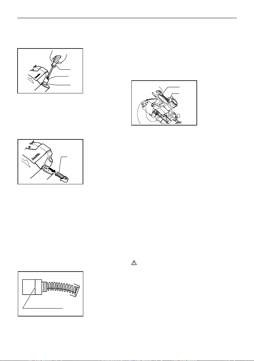
Cleaning of the lens for the laser light
For model LS1016L only
1. Screwdriver
2. Screw (one
piece only)
3. Lens for the
1
laser light
2
3
009609
If the lens for the laser light becomes dirty, or sawdust
adheres to it in such a way that the laser line is no longer
easily visible, unplug the saw and remove and clean the
lens for the laser light carefully with a damp, soft cloth.
Do not use solvents or any petroleum-based cleaners on
the lens.
1. Lens for the
laser light
1
009610
To remove the lens for the laser light, remove the saw
blade before removing the lens according to the
instructions in the section titled "Installing or removing
saw blade".
Loosen but do not remove the screw which secures the
lens using a screwdriver.
Pull out the lens as shown in the figure.
NOTE:
• If the lens does not come out, loosen the screw
further and pull out the lens again without removing
the screw.
Replacing carbon brushes
1. Limit mark
1
001145
Remove and check the carbon brushes regularly.
Replace when they wear down to the limit mark. Keep
the carbon brushes clean and free to slip in the holders.
Both carbon brushes should be replaced at the same
time. Use only identical carbon brushes.
Use a screwdriver to remove the brush holder caps.
Take out the worn carbon brushes, insert the new ones
and secure the brush holder caps.
1
2
009516
1. Screwdriver
2. Brush holder
cap
After replacing brushes, plug in the tool and break in
brushes by running tool with no load for about 10
minutes. Then check the tool while running and electric
brake operation when releasing the switch trigger. If
electric brake is not working well, ask your local Makita
service center for repair.
After use
• After use, wipe off chips and dust adhering to the
tool with a cloth or the like. Keep the blade guard
clean according to the directions in the previously
covered section titled "Blade guard". Lubricate the
sliding portions with machine oil to prevent rust.
• When storing the tool, pull the carriage toward you
fully so that the slide pole is thoroughly inserted
into the turn base.
To maintain product SAFETY and RELIABILITY, repairs,
any other maintenance or adjustment should be
performed by Makita Authorized or Factory Service
Centers, always using Makita replacement parts.
ACCESSORIES
CAUTION:
• These accessories or attachments are
recommended for use with your Makita tool
specified in this manual. The use of any other
accessories or attachments might present a risk of
injury to persons. Only use accessory or
attachment for its stated purpose.
If you need any assistance for more details regarding
these accessories, ask your local Makita Service Center.
• Steel & Carbide-tipped saw blades
24
Page 25

Miter saw blades
Combination
Crosscutting
Fine cross cuts For sand-free cuts cleanly against the grain.
Non-ferrous metals
miter saw blades
006526
For smooth and precise cutting in various materials.
General purpose blade for fast and smooth rip,
crosscuts and miters.
For smoother cross grain cuts. Slices cleanly
against the grain.
For miters in aluminum, copper, brass, tubing,
and other non-ferrous metals.
• Vise assembly (Horizontal vise)
• Ver ti cal vise
• Socket wrench 13
• Holder
• Dust bag
• Crown molding stopper set
• Triangular rule
• Dust box
• Hex wrench (for LS1016L)
MAKITA LIMITED ONE YEAR WARRANTY
Warranty Policy
Every Makita tool is thoroughly inspected and tested
before leaving the factory. It is warranted to be free of
defects from workmanship and materials for the period
of ONE YEAR from the date of original purchase.
Should any trouble develop during this one year period,
return the COMPLETE tool, freight prepaid, to one of
Makita’s Factory or Authorized Service Centers. If
inspection shows the trouble is caused by defective
workmanship or material, Makita will repair (or at our
option, replace) without charge.
This Warranty does not apply where:
repairs have been made or attempted by others:
repairs are required because of normal wear and
tear:
the tool has been abused, misused or improperly
maintained:
alterations have been made to the tool.
IN NO EVENT SHALL MAKITA BE LIABLE FOR ANY
INDIRECT, INCIDENTAL OR CONSEQUENTIAL
DAMAGES FROM THE SALE OR USE OF THE
PRODUCT. THIS DISCLAIMER APPLIES BOTH
DURING AND AFTER THE TERM OF THIS
WARRANTY.
MAKITA DISCLAIMS LIABILITY FOR ANY IMPLIED
WARRANTIES, INCLUDING IMPLIED WARRANTIES
OF "MERCHANTABILITY" AND "FITNESS FOR A
SPECIFIC PURPOSE," AFTER THE ONE YEAR TERM
OF THIS WARRANTY.
This Warranty gives you specific legal rights, and you
may also have other rights which vary from state to
state. Some states do not allow the exclusion or
limitation of incidental or consequential damages, so
the above limitation or exclusion may not apply to you.
Some states do not allow limitation on how long an
implied warranty lasts, so the above limitation may not
apply to you.
EN0006-1
25
Page 26

FRANÇAIS
SPÉCIFICATIONS
Modèle LS1016/LS1016L
Diamètre de la lame 255 mm (10")
Diamètre de l'orifice 15.88 mm (5/8")
Capacités de coupe maximales (H x P)
Angle de coupe d'onglet
0°
45° (Gauche) 0° 45° (droite)
47 mm x 305 mm
(1-7/8"x12")
61 mm x 279 mm
(2-3/8"x11")
47 mm x 215 mm
45°(droite et gauche)
(1-7/8"x 8-1/2")
61 mm x 197 mm
(2-3/8"x 7-3/4")
52°(droite et gauche) -
60°(droite) -
Capacités spéciales de coupe max
Moulure couronnée du type 45°
(avec l'utilisation de la butée de moulure couronnée)
Plinthe (H)
(avec l’utilisation de l’étau horizontal)
Vitesse à vide (T/MIN) 3,200/min
Type de laser (LS1016L uniquement)
Longueur d'ondes 650 nm, sortie maximale 1mW (Laser Classe II)
Dimensions (L x P x H) 718 mm x 640 mm x 671 mm
(28-1/4" x 25-1/4"x 26-1/2")
Poids net 23.7 kg (52.2 lbs)
• Étant donné l'évolution constante de notre programme de recherche et de développement, les spécifications contenues dans ce
manuel sont sujettes à modification sans préavis.
• Note : Les spécifications peuvent varier suivant les pays.
• Poids conforme à la procédure EPTA du 01/2003
26
Angle de coupe en biseau
71 mm x 305 mm
(2-13/16"x12")
91 mm x 279 mm
(3-5/8"x11")
71 mm x 215 mm
(2-13/16"x 8-1/2")
91 mm x 197 mm
(3-5/8"x 7-3/4")
25 mm x 187 mm
(1"x 7-3/8")
91 mm x 91 mm
(3-5/8"x 3-5/8")
25 mm x 152 mm
(1"x 6")
91 mm x 76 mm
(3-5/8"x 3")
168 mm (6-5/8")
120 mm (4-3/4")
29 mm x 305 mm
(1-1/8"x12")
43 mm x 279 mm
(1-11/16"x11")
29 mm X 215 mm
(1-1/8"x 8-1/2")
43 mm x 197 mm
(1-11/16"x 7-3/4")
-
-
Page 27

USA007-2
Pour votre propre sécurité,
veuillez lire le manuel
d'instructions
Avant d'utiliser l'outil
Conservez-le pour référence
ultérieure
PRÉCAUTIONS GÉNÉRALES
(POUR TOUS LES OUTILS)
1. VOUS DEVEZ CONNAÎTRE VOTRE OUTIL
ÉLECTRIQUE. Lisez attentivement le manuel
d'instructions. Familiarisez-vous avec les
applications et limites de l'outil, ainsi qu'avec
les risques potentiels qui lui sont spécifiques.
2. MAINTENEZ LES PROTECTEURS EN PLACE
et en bon état de fonctionnement.
3. RETIREZ LES CLÉS DE RÉGLAGE ET DE
SERRAGE. Prenez l'habitude de vous assurer
que les clés de réglage et de serrage ont été
retirées de l'outil avant de le mettre sous
tension.
4. MAINTENEZ LA ZONE DE TRAVAIL PROPRE.
Les zones de travail et les établis encombrés
ouvrent grande la porte aux accidents.
5. ÉVITEZ L'UTILISATION DANS UN
ENVIRONNEMENT DANGEREUX. N'utilisez
pas les outils électriques dans les endroits
humides ou mouillés, et ne les exposez pas à
la pluie. Maintenez un éclairage adéquat dans
la zone de travail. Ne vous servez pas de votre
outil en présence de liquides ou gaz
inflammables.
6. MAINTENEZ LES ENFANTS À L'ÉCART. Toute
autre personne que l'utilisateur de l'outil doit
se tenir à une distance sûre de l'aire de travail.
7. FAITES EN SORTE QUE L'ATELIER SOIT
SANS DANGER POUR LES ENFANTS, en y
posant des cadenas, un interrupteur principal,
ou en retirant des équipements leurs clés de
démarrage.
8. NE FORCEZ PAS L'OUTIL. Il effectuera un
travail de meilleure qualité et plus sécuritaire
s'il est utilisé au régime pour lequel il a été
conçu.
9. UTILISEZ LE BON OUTIL. Ne forcez pas un
outil ou accessoire à effectuer un travail pour
lequel il n'a pas été conçu.
10. PORTEZ DES VÊTEMENTS ADÉQUATS. Ne
portez ni vêtements ni gants amples, ni
cravate, anneaux/bagues, bracelets ou autres
bijoux susceptibles d'être happés par les
pièces mobiles de l'outil. Le port de
chaussures antidérapantes est recommandé.
Portez un filet de protection pour envelopper
les cheveux longs.
11. PORTEZ TOUJOURS DES LUNETTES DE
SÉCURITÉ. Si le travail de coupe dégage de la
poussière, portez également un écran facial
ou un masque antipoussières. Les lunettes
ordinaires ne sont munies que de lentilles
résistances aux chocs ; elles ne constituent
PAS des lunettes de sécurité.
12. FIXEZ BIEN LA PIÈCE. Lorsque cela est
possible, fixez la pièce à travailler à l'aide de
dispositifs de serrage ou d'un étau. Cela est
plus sécuritaire que l'utilisation de la main et
libère les deux mains pour le maniement de
l'outil.
13. MAINTENEZ UNE BONNE POSITION.
Assurez-vous d'une bonne prise au sol et
d'une bonne position d'équilibre en tout
temps.
14. PRENEZ SOIN DES OUTILS. Maintenez les
outils bien aiguisés et propres pour assurer
une performance sécuritaire et optimale.
Suivez les instructions de lubrification et de
changement des accessoires.
15. DÉBRANCHEZ LES OUTILS avant tout travail
de réparation ou avant de changer les
accessoires tels que lames,
embouts/forets/fraises et couteaux.
16. RÉDUISEZ LES RISQUES DE MISE EN
MARCHE ACCIDENTELLE. Assurez-vous que
l'interrupteur est en position d'arrêt avant de
brancher l'outil.
17. UTILISEZ LES ACCESSOIRES
RECOMMANDÉS. Consultez le manuel de
l'utilisateur pour savoir quels sont les
accessoires recommandés. L'utilisation
d'accessoires non adéquats peut comporter
un risque de blessure.
18. NE VOUS APPUYEZ JAMAIS SUR L'OUTIL.
Vous courez un risque de blessure grave si
l'outil bascule ou si vous touchez
accidentellement l'outil tranchant.
27
Page 28

19. VÉRIFIEZ S'IL Y A DES PIÈCES
ENDOMMAGÉES. Avant d'utiliser l'outil, tout
protecteur ou dispositif endommagé doit être
vérifié soigneusement afin de s'assurer qu'il
fonctionne adéquatement et peut remplir la
fonction pour laquelle il est conçu. Vérifiez si
les pièces mobiles sont bien alignées et bien
fixées, vérifiez la présence de pièces brisées,
vérifiez que l'outil est bien monté et
assurez-vous que rien ne peut entraver son
bon fonctionnement. Un protecteur ou tout
autre dispositif endommagé doit être
adéquatement réparé ou remplacé.
20. SENS D'ALIMENTATION. Vous devez faire
avancer la pièce à l'encontre de la lame ou de
l'outil tranchant, non la faire progresser dans
le même sens.
21. NE LAISSEZ JAMAIS SANS SURVEILLANCE
UN OUTIL EN MARCHE. COUPEZ LE
CONTACT. Attendez que l'outil se soit
complètement arrêté avant de le quitter.
22. PIÈCES DE RECHANGE. Seules des pièces de
rechange identiques aux originales doivent
être utilisées lors des réparations.
23. FICHES POLARISÉES. Pour réduire les
risques de choc électrique, cet appareil est
muni d'une fiche polarisée (une des lames est
plus large que l'autre). Cette fiche ne peut être
insérée dans une prise polarisée que dans un
seul sens. Si la fiche ne s'insère pas à fond
dans la prise, insérez-la en sens inverse. Si
elle ne s'insère toujours pas à fond, contactez
un technicien qualifié pour faire installer une
prise appropriée. N'apportez aucune
MISE EN GARDE RELATIVE À LA TENSION : avant
de brancher l'outil sur une source d'alimentation
(prise ou autre dispositif), assurez-vous que la
tension du circuit correspond à celle qui est
spécifiée sur la plaque signalétique de l'outil.
L'utilisation d'une source d'alimentation dont la
tension est supérieure à celle spécifiée pour l'outil
peut entraîner une GRAVE BLESSURE et
endommager l'outil. En cas de doute, NE
BRANCHEZ PAS L'OUTIL. L'utilisation d'une source
d'alimentation dont la tension est inférieure à la
valeur indiquée sur la plaque signalétique
endommagera le moteur.
UTLISEZ UN CORDON PROLONGATEUR ADÉQUAT.
Assurez-vous que le cordon prolongateur est en
bon état. Lors de l'utilisation d'un cordon
prolongateur, utilisez sans faute un cordon assez
gros pour conduire le courant que l'outil nécessite.
Un cordon trop petit provoquera une baisse de
tension de secteur, résultant en une perte de
puissance et une surchauffe. Le Tableau 1 indique la
dimension appropriée de cordon selon sa longueur
et selon l'intensité nominale indiquée sur la plaque
signalétique. En cas de doute sur un cordon donné,
utilisez le cordon suivant (plus gros). Plus le numéro
de gabarit indiqué est petit, plus le cordon est gros.
modification à la fiche.
Tableau 1. Gabarit minimum du cordon
Intensit
é nominale
Volts Longueur totale du cordon en pieds
120 V 25 pi 50 pi 100 pi 150 pi
Plus de Pas plus de Calibre am
0 6 18 16 16 14
10 12 16 16 14 12
000173
12 16 14 12
éricain des fils
18 16 14 12610
Non recommand
é
28
Page 29

USB036-2
RÈGLES DE SÉCURITÉ
SUPPLÉMENTAIRES
NE vous laissez PAS tromper (au fil d'une utilisation
répétée) par un sentiment d'aisance et de familiarité
avec le produit, en négligeant le respect rigoureux
des consignes de sécurité qui accompagnent la scie
à chariot mixte. L'utilisation non sécuritaire ou
incorrecte de cet outil comporte un risque de
blessure grave.
1. Portez un protecteur pour la vue.
2. Maintenez les mains hors de la ligne de coupe
de la lame. Évitez tout contact avec la lame
lorsqu'elle continue de tourner après la mise
hors tension de l'outil. Elle peut alors quand
même causer de graves blessures.
3. N'utilisez jamais la scie sans les protections
en place. Assurez-vous avant chaque
utilisation que le protecteur de lame se
referme bien. N'utilisez pas la scie si le
protecteur de lame ne se déplace pas
librement et ne se referme pas instantanément.
Ne fixez ou n'attachez jamais le protecteur de
lame en position ouverte.
4. N'effectuez aucune opération en tenant la
pièce uniquement avec la main. La pièce doit
être fixée fermement contre le socle rotatif et
le garde de guidage avec un étau lors de
toutes les opérations. N'utilisez jamais la main
pour immobiliser la pièce.
5. N'approchez jamais les mains de la lame.
6. Coupez le contact et attendez l'arrêt de la lame
avant de déplacer la pièce ou de modifier les
réglages.
7. Débranchez l'outil avant le changement de
lame ou la réparation.
8. Pour réduire les risques de blessure, ramenez
le chariot complètement vers l'arrière après
chaque opération de coupe en travers.
9. Avant de transporter l'outil, immobilisez
d'abord toutes ses pièces mobiles.
10. La broche de blocage qui verrouille en
position basse le porte-lame est conçue
exclusivement pour le transport et le
rangement de l'outil, et ne doit être utilisée
pour aucun travail de coupe.
11. N'utilisez pas l'outil en présence de liquides
ou gaz inflammables.
12. Avant l'utilisation, vérifiez toujours
soigneusement l'absence de fissures ou de
dommages sur la lame. Veuillez remplacer
immédiatement toute lame fissurée ou
endommagée. La présence de résine et de
goudron sur la lame ralentit la scie et entraîne une
augmentation des risques de recul. Pour nettoyer
la lame, retirez-la d'abord de l'outil, puis utilisez un
décapant, de l'eau chaude ou du kérosène pour
retirer la colle et les copeaux. N'utilisez jamais
d'essence.
13. Un RECUL peut se produire lors d'une coupe
en glissière. Un RECUL se produit lorsque la
lame se coince dans la pièce pendant la coupe
et se trouve soudainement ramenée vers
l'utilisateur. Il peut en résulter une perte de
maîtrise de l'outil et une grave blessure. Si la
lame commence à se coincer dans la pièce
pendant la coupe, interrompez la coupe et
relâchez immédiatement l'interrupteur.
14. Utilisez exclusivement les flasques spécifiés
pour cet outil.
15. Prenez garde d'endommager l'arbre, les
flasques (tout particulièrement leur surface
d'installation) ou le boulon.
L'endommagement de ces pièces peut causer
une cassure de la lame.
16. Assurez-vous que le socle rotatif est bien
immobilisé, de sorte qu'il ne bouge pas
pendant l'opération. Fixez la scie à une
surface de travail ou à un établi stable au
moyen des orifices de la base. N'utilisez
JAMAIS l'outil si vous vous trouvez dans une
position qui n'assure pas une pleine liberté de
mouvement.
17. Pour votre sécurité, retirez les copeaux et
autres petites pièces présentes sur la table
avant de commencer le travail.
18. Évitez les clous. Avant de travailler votre pièce,
inspectez-la et retirez-en tous les clous.
19. Assurez-vous que le blocage de l'arbre est
libéré avant de mettre le contact.
20. Assurez-vous que la lame n'entre pas en
contact avec le socle rotatif lorsqu'elle se
trouve sur sa position la plus basse.
21. Tenez la poignée fermement. N'oubliez pas
que la scie se déplace légèrement vers le haut
ou le bas au démarrage et à l'arrêt.
22. Assurez-vous que la lame n'entre pas en
contact avec la pièce avant de mettre l'outil
sous tension.
29
Page 30

23. Avant d'utiliser l'outil sur la pièce, laissez-le
tourner à vide un instant. Soyez attentif à toute
vibration ou sautillement pouvant indiquer
que la lame n'est pas bien installée ou est mal
équilibrée.
24. Attendez que la lame atteigne sa pleine
vitesse avant de procéder à la coupe.
25. Arrêtez immédiatement votre outil dès que
vous observez quelque chose d'anormal.
26. N'essayez pas de verrouiller la gâchette en
position de marche.
27. Demeurez attentif en tout temps, et tout
particulièrement lors des travaux répétitifs et
monotones. Ne vous laissez pas emporter par
un sentiment de sécurité trompeur. Les lames
ne pardonnent pas.
28. Utilisez toujours les accessoires
recommandés dans le présent manuel.
L'utilisation d'accessoires inadéquats, tels
que les meules abrasives par exemple, peut
entraîner une blessure.
29. Ne tenez JAMAIS la pièce du côté droit de la
scie avec la main gauche, et vice versa. Cela
s'appelle une coupe à bras croisé et expose
l'utilisateur à un RISQUE DE GRAVE
BLESSURE, tel qu'indiqué sur l'illustration.
Utilisez TOUJOURS un étau pour immobiliser
la pièce.
000030
30. Ne maltraitez pas le cordon. Ne tirez jamais
directement sur le cordon pour le débrancher
de la prise. Maintenez le cordon à l'écart de la
chaleur, de l'huile, de l'eau et des objets
tranchants.
31. N'empilez JAMAIS plusieurs pièces sur la
table de travail pour accélérer le travail de
coupe. Coupez les pièces une à la fois.
32. Certains matériaux contiennent des produits
chimiques qui peuvent être toxiques. Prenez
les précautions nécessaires pour éviter
l'inhalation de ces poussières ou leur contact
avec la peau. Conformez-vous aux consignes
de sécurité du fournisseur du matériau.
CONSERVEZ CE MODE
D'EMPLOI.
AVERTISSEMENT:
Une MAUVAISE UTILISATION de l'outil ou
l'ignorance des consignes de sécurité du présent
manuel d'instructions peuvent entraîner une grave
blessure.
USB094-1
RÈGLES DE SÉCURITÉ
ADDITIONNELLES POUR LE
LASER
ATT EN TI ON :
• RAYONNEMENT LASER, NE PAS REGARDER
DIRECTEMENT LE RAYON.
• ÉVITEZ L'EXPOSITION – UN RAYONNEMENT
LASER EST ÉMIS PAR L'OUVERTURE.
• IL Y A DANGER D'EXPOSITION AU
RAYONNEMENT LASER SI DES COMMANDES
OU RÉGLAGES AUTRES QUE CEUX
SPÉCIFIÉS DANS LE PRÉSENT MANUEL SONT
EXÉCUTÉS.
Complies with 21CFR
1040.10 and 1040.11
AVOID EXPOSURE-Laser
radiation is emitted from
this aperture
CAUTION
LASER RADIATION
DO NOT STARE INTO BEAM
Maximum Output
<1mW,Wavelength:655nm
CLASS II LASER PRODUCT
009605
Pose
Montage du banc
À sa sortie d'usine, la poignée de cet outil est verrouillée
en position basse par la broche de blocage. Pour
dégager la broche de blocage, abaissez légèrement la
poignée et tirez sur la broche.
30
Page 31

1
009483
Cet outil doit être boulonné sur une surface plane et
stable avec quatre boulons, en utilisant les trous
d'éclissage pratiqués dans la base de l'outil. Cela aidera
à prévenir les risques de basculement et de blessure.
1
009484
1. Broche de
blocage
1. Boulon
hexagonal
DESCRIPTION DU
FONCTIONNEMENT
ATT EN TI ON :
• Assurez-vous toujours que l'outil est hors tension
et débranché avant de l'ajuster ou de vérifier son
fonctionnement.
Protecteur de lame
1. Protecteur de
lame
Pour votre propre sécurité, maintenez toujours le
protecteur de lame en bonne condition. Tout
fonctionnement irrégulier du protecteur de lame doit être
corrigé immédiatement. Assurez-vous que le
mécanisme de rappel du protecteur fonctionne
correctement. NE JAMAIS UTILISER L'OUTIL SI LE
PROTECTEUR DE LAME OU LE RESSORT EST
ENDOMMAGÉ, DÉFECTUEUX OU RETIRÉ. CELA EST
EXTRÊMEMENT DANGEREUX ET PEUT CAUSER
UNE GRAVE BLESSURE.
Si le protecteur de lame transparent devient sale ou si la
sciure de bois y adhère au point que la lame et/ou la
pièce ne soit plus bien visible, débranchez la scie et
nettoyez soigneusement le protecteur avec un chiffon
humide. N'utilisez pas de solvants ni de détergents à
base d'essence sur le protecteur en plastique.
Lorsque le protecteur est très sale et qu'il n'est plus
possible de voir à travers, utilisez la clé à douille fournie
pour desserrer le boulon hexagonal qui retient le
couvercle central. Desserrer le boulon hexagonal en le
faisant tourner dans le sens inverse des aiguilles d'une
montre, puis soulevez le protecteur de lame et le
couvercle central. Le nettoyage du protecteur de lame
peut être effectué de manière plus complète et efficace
lorsqu'il se trouve dans cette position. Une fois le
nettoyage terminé, effectuez la procédure ci-dessus en
sens inverse et fixez le boulon. Ne retirez pas le ressort
du protecteur de lame. Lorsque le protecteur se
décolore avec le temps ou sous l'effet des rayons
ultraviolets, contactez un centre de service après-vente
Makita pour vous procurer un nouveau protecteur. NE
PAS MODIFIER OU RETIRER LE PROTECTEUR.
1. Protecteur de
lame
1
009485
Le protecteur de lame s'élève automatiquement lorsque
vous abaissez la poignée. Le protecteur étant équipé
d'un ressort de rappel, il revient à sa position d'origine
une fois la coupe terminée et la poignée relevée. NE
JAMAIS MODIFIER OU RETIRER LE PROTECTEUR
DE LAME OU SON RESSORT.
1
009486
Positionnement du plateau de découpe
1. Plateau de
1
009488
31
découpe
Page 32

1
2
3
4
5
6
001538
Le socle rotatif de cet outil est équipé de plateaux de
découpe pour réduire la déchirure du côté extérieur de
la coupe. Les plateaux de découpe sont réglés en usine
de sorte qu'ils n'entrent pas en contact avec la lame.
Avant l'utilisation, ajustez les plateaux de découpe
comme suit:
009496
Débranchez d'abord l'outil. Desserrez toutes les vis (2,
une à gauche, une à droite) qui immobilisent les
plateaux de découpe. Resserrez-les de façon à pouvoir
déplacer facilement les plateaux de découpe
manuellement. Abaissez complètement la poignée et
enfoncez la broche d'arrêt pour verrouiller la poignée
dans cette position. Desserrez la vis de verrouillage en
la tournant dans le sens inverse des aiguilles d'une
montre, ce qui immobilise les tiges de glissement
supérieures, et poussez le levier de blocage vers l'avant,
ce qui immobilise les tiges de glissement inférieures.
Tirez complètement le chariot vers vous. Réglez les
plateaux de découpe de sorte qu'ils n'entrent en contact
qu'avec les côtés des dents de la lame. Serrez les vis
avant (ne les serrez pas fermement). Poussez
complètement le chariot vers le garde de guidage et
réglez les plateaux de découpe de sorte qu'ils n'entrent
en contact qu'avec les côtés des dents de la lame.
Serrez les vis arrière (ne les serrez pas fermement).
1
1. Lame
2. Dents de la lame
3. Plateau de
découpe
4. Coupe en
biseau sur la
gauche
5. Coupe rectiligne
6. Coupe en
biseau sur la
droite
1. Levier de
verrouillage
2. Vis
2
Après le réglage des plateaux de découpe, relâchez la
broche de blocage et soulevez la poignée. Puis serrez
toutes les vis fermement.
ATT EN TI ON :
• Avant et après la modification de l'angle de coupe
en biseau, ajustez toujours les plateaux de
découpe de la façon décrite ci-dessus.
Maintien de la capacité de coupe maximale
Débranchez l'outil avant d'y entreprendre tout réglage.
Cet outil est réglé en usine de sorte que sa capacité de
coupe maximale soit atteinte avec une lame de 255 mm
(10'').
Lorsque vous posez une nouvelle lame, vérifiez toujours
la position limite inférieure de la lame, et réglez-la
comme suit au besoin:
1
3
4
2
1. Boulon de réglage
2. Socle rotatif
3. Levier de blocage
4. Tuyau de la glissière
009518
2
1
009737
1
009736
1. Face supérieure
du socle rotatif
3
2. Bord de la lame
3. Garde de
guidage
1. Levier de
blocage
32
Page 33

Débranchez d’abord l’outil. Abaissez le levier de blocage
pour positionner la lame de la façon indiquée sur
l’illustration. Poussez complètement le chariot vers le
garde de guidage et abaissez totalement la poignée.
Utilisez la clé à douille pour tourner le boulon de réglage
jusqu’à ce que le tranchant de la lame dépasse
légèrement sous la face supérieure du socle rotatif au
point de rencontre entre le garde de guidage et la face
supérieure du socle rotatif.
Débranchez l'outil et faites tourner la lame
manuellement en maintenant la poignée en position
parfaitement abaissée, pour être sûr que la lame n'entre
en contact avec aucune partie de la base inférieure. Au
besoin, effectuez un léger réajustement.
Après le réglage, replacez toujours le levier de blocage
à sa position d'origine en le tournant dans le sens
inverse des aiguilles d'une montre.
ATT EN TI ON :
• Après avoir posé une nouvelle lame, assurez-vous
toujours qu'elle n'entre en contact avec aucune
partie de la base inférieure lorsque la poignée est
complètement abaissée. Débranchez toujours
l'outil avant d'effectuer cette opération.
Bras de blocage
1. Bras de blocage
2
1
2. Vis de réglage
Poussez le manche de sorte que la came s'engage et
tournez-le dans le sens des aiguilles d'une montre
jusqu'à ce qu'il se bloque. Tournez le socle rotatif en
appuyant sur le levier de blocage. Lorsque vous avez
déplacé le manche de sorte que le pointeur indique
l'angle désiré sur l'échelle de coupe d'onglet, tournez le
manche de 90° dans le sens inverse des aiguilles d'une
montre pour verrouiller le socle rotatif.
ATT EN TI ON :
• Assurez-vous de soulever complètement la
poignée lorsque vous faites tourner le socle rotatif.
• Après avoir modifié l'angle de coupe d'onglet,
immobilisez toujours le socle rotatif en tournant le
manche de 90° dans le sens inverse des aiguilles
d'une montre.
Réglage de l'angle de coupe en biseau
Pour régler l’angle de biseau, desserrez le levier à
l’arrière de l’outil en le tournant dans le sens inverse des
aiguilles d’une montre. Poussez le levier de fermeture
complètement vers l’avant et déverrouillez le bras en
poussant légèrement la poignée dans la direction
d'inclinaison de la lame.
Lors de l'inclinaison du chariot vers la droite, inclinez le
chariot légèrement vers la gauche après avoir desserré
le levier et appuyez sur le bouton de déblocage. Tout en
appuyant sur le bouton de déblocage, inclinez le chariot
vers la droite.
2
1. Levier
2. Levier de
fermeture
009487
Le bras de blocage permet un réglage facile de la
position limite inférieure de la lame. Pour l'ajuster,
tournez le bras de blocage dans le sens de la flèche, tel
qu'indiqué sur la figure. Ajustez la vis de réglage de
sorte que la lame s'arrête à la position désirée lorsque la
poignée est complètement abaissée.
Réglage de l'angle de coupe d'onglet
1. Levier de
1
3
009517
verrouillage
2. Poignée
3. Came
2
1
009489
Inclinez la lame jusqu'à ce que le pointeur indique
l'angle désiré sur l'échelle de coupe en biseau. Serrez
ensuite le levier fermement dans le sens des aiguilles
d'une montre pour fixer le bras.
1. Secteur
angulaire
2. Bouton de
libération
3. Index
4. Levier de
fermeture
3
2
009513
4
1
33
Page 34

Lorsque vous tirez le levier de fermeture vers vous, la
lame peut être verrouillée à l'aide des arrêts positifs sur
les angles droit et gauche 22,5° et 33,9° à la surface du
socle.
Lorsque vous poussez le levier de fermeture vers le
support du bras, la lame peut être verrouillée à un angle
voulu dans la plage d'angle de biseau spécifiée.
ATT EN TI ON :
• Assurez-vous de soulever complètement la
poignée lorsque vous inclinez la lame.
• Après avoir modifié l'angle de coupe en biseau,
fixez toujours le bras en serrant le levier dans le
sens des aiguilles d'une montre.
• Lorsque vous modifiez l'angle de coupe en biseau,
assurez-vous toujours de bien placer les plateaux
de découpe, tel que décrit dans la section
"Positionnement des plateaux de découpe."
Réglage du verrou de la glissière
1. Levier de
verrouillage
2. Vis
2
009496
Pour verrouiller la tige de glissement inférieure, tirez le
levier de blocage vers vous.
Pour verrouiller la tige de glissement supérieure, tournez
la vis de verrouillage dans le sens des aiguilles d'une
1
montre.
Interrupteur
ATT EN TI ON :
• Avant de brancher l'outil, assurez-vous toujours
que la gâchette fonctionne correctement et revient
en position d'arrêt une fois relâchée.
• N'appuyez pas fortement sur la gâchette sans
avoir d'abord enfoncé le bouton de sécurité. Vous
risqueriez de briser la gâchette.
009491
1. Gâchette
2. Bouton de
sécurité
3. Trou pour
cadenas
1
3
2
Un bouton de sécurité est fourni pour prévenir la
pression accidentelle sur la gâchette. Pour faire
démarrer l'outil, appuyez sur le bouton de sécurité puis
sur la gâchette. Pour l'arrêter, relâchez la gâchette.
Un trou a été prévu dans la gâchette pour l'insertion d'un
cadenas permettant de déverrouiller l'outil.
AVERTISSEMENT:
• N'utilisez pas un verrou dont la tige ou le câble a
un diamètre inférieur à 6,35 mm (1/4").
• NE JAMAIS utiliser un outil dont la gâchette ne
fonctionne pas parfaitement. Tout outil dont la
gâchette est inopérante est EXTRÊMEMENT
DANGEREUX et doit faire l'objet d'une réparation
avant d'être à nouveau utilisé.
• Pour assurer votre sécurité, cet outil est équipé
d'un bouton de sécurité qui prévient le démarrage
de l'outil par inadvertance. NE JAMAIS utiliser
l'outil s'il se met en marche sur simple pression de
la gâchette alors que vous n'avez pas appuyé sur
le bouton de sécurité. Retournez alors l'outil à un
centre de service après-vente Makita pour le faire
réparer AVANT d'en poursuivre l'utilisation.
• Le bouton de sécurité ne doit JAMAIS être
immobilisé avec de la bande adhésive ou modifié.
Frein électrique
Cet outil est équipé d'un frein à lame électrique. Si à
plusieurs reprises l'outil ne s'arrête pas rapidement
après le relâchement de la gâchette, faites-le réparer
dans un centre de service après-vente Makita.
Le mécanisme de frein à lame ne doit pas être utilisé en
remplacement du protecteur de lame. N'UTILISEZ
JAMAIS L'OUTIL LORSQUE LE PROTECTEUR DE
LAME NE FONCTIONNE PAS. CELA COMPORTE DES
RISQUES DE BLESSURE GRAVE.
Fonction électronique
Commande de vitesse constante
• La vitesse de rotation étant maintenue constante
même dans des conditions de lourde charge de
travail, il est possible d'atteindre une grande
finesse de finition.
• De plus, lorsque la charge imposée à l'outil
dépasse le niveau permis, l'alimentation du moteur
est réduite pour le protéger contre la surchauffe.
Le fonctionnement normal de l'outil est rétabli
lorsque la charge imposée revient à un niveau
permis.
Fonction de démarrage en douceur
• La suppression du choc de démarrage permet un
démarrage en douceur.
34
Page 35

Action du faisceau laser
Pour le modèle LS1016L uniquement
1. Interrupteur du
Alignement de la ligne laser
AB
laser
1
009492
ATT EN TI ON :
• RAYONNEMENT LASER
Ne pas regarder directement le rayon.
Pour allumer le faisceau laser, appuyez sur la position
supérieure (I) de l'interrupteur. Appuyez sur sa position
inférieure (O) pour éteindre.
En ajustant la vis de réglage comme suit, vous pouvez
déplacer la ligne laser du côté gauche ou droit de la
lame.
1. Vis de réglage
1
009493
1. Desserrez la vis de réglage en la tournant dans le
sens inverse des aiguilles d'une montre.
2. Une fois la vis de réglage desserrée, glissez-la
complètement vers la droite ou la gauche.
3. Serrez fermement la vis de réglage jusqu'à la
position où elle cesse de glisser.
La ligne laser est ajustée en usine pour se trouver à
moins de 1 mm (0.04") de la face latérale de la lame
(position de coupe).
NOTE:
• Si la ligne de coupe est trop pâle et presque
imperceptible parce que vous travaillez dans un
endroit exposé directement aux rayons du soleil ou
près d'une fenêtre intérieure ou extérieure,
changez de zone de travail pour ne plus être
exposé directement aux rayons du soleil.
009494
Suivant le type de coupe à effectuer, vous pouvez
déplacer la ligne laser du côté gauche ou droit de la
lame. Reportez-vous à l'explication intitulée "Action du
faisceau laser" concernant la façon de le déplacer.
NOTE:
• Placez un parement de bois contre le garde de
guidage lorsque vous alignez la ligne de coupe sur
la ligne laser à côté du garde de guidage pour
effectuer une coupe mixte (coupe en biseau de 45
degrés et coupe d'onglet de 45 degrés sur la
droite).
A) Pour obtenir la taille désirée du côté gauche de la
pièce à travailler
• Placez la ligne laser du côté gauche de la lame.
B) Pour obtenir la taille désirée du côté droit de la pièce
à travailler
• Placez la ligne laser du côté droit de la lame.
Alignez votre ligne de coupe avec la ligne laser sur la
pièce à travailler.
ASSEMBLAGE
ATT EN TI ON :
• Avant d'effectuer toute intervention sur l'outil,
assurez-vous toujours qu'il est hors tension et
débranché.
Rangement de la clé à douille
1
009495
1. Support à clé
2. Clé à douille
2
35
Page 36

Le rangement de la clé à douille s'effectue de la façon
indiquée sur l'illustration. Pour utiliser la clé à douille,
retirez-la du support à clé. Après avoir utilisé la clé à
douille, remettez-la dans le support à clé.
Pose et retrait de la lame de scie
ATT EN TI ON :
• Assurez-vous toujours que l'outil est hors tension
et débranché avant de poser ou de retirer la lame.
• Utilisez exclusivement la clé à douille Makita
fournie pour poser ou retirer la lame. Sinon, le
boulon hexagonal risque d'être trop ou pas assez
serré. Cela peut entraîner une blessure.
Verrouillez la poignée en position élevée en y poussant
la broche de blocage.
1
009483
1. Broche de
blocage
Pour retirer la lame, utiliser la clé à douille pour
desserrer le boulon hexagonal qui retient le couvercle
central, en tournant dans le sens inverse des aiguilles
d'une montre. Soulevez le protecteur de lame et le
couvercle central.
1
2
1. Couvercle
3
2. Clé à douille
3. Boulon
4. Protecteur de
central
hexagonal
lame
4
009497
Appuyez sur le blocage de l'arbre pour verrouiller l'arbre,
et utilisez la clé à douille pour desserrer le boulon
hexagonal dans le sens des aiguilles d'une montre.
Retirez ensuite le boulon hexagonal, le flasque extérieur
et la lame.
1. Verrouillage de
l'arbre
2
2. Boîtier de la
lame
3. Boulon
hexagonal
1
3
009498
NOTE:
• Lorsque le flasque intérieur est retiré par erreur,
assurez-vous de l'installer sur l'axe, sa
protubérance face à l'axe.
Pour installer la lame, montez-la soigneusement sur
l'axe en vous assurant que le sens indiqué par la flèche
sur la surface de la lame correspond à celui de la flèche
du carter de lame.
Installez le flasque extérieur et le boulon hexagonal, puis,
à l'aide de la clé à douille, serrez à fond le boulon
hexagonal (filetage à gauche) en le tournant vers la
gauche tout en appuyant sur le blocage de l'arbre.
1
34
009500
1. Flèche
2
2. Flèche
3. Boîtier de la
lame
4. Lame
1
009499
2
3
4
1. Boulon
hexagonal
2. Bague externe
3. Lame
4. Bague interne
5. Axe
5
36
Page 37

Remettez le protecteur de lame et le couvercle central
en position initiale. Serrez ensuite le boulon hexagonal
dans le sens des aiguilles d'une montre pour fixer le
couvercle central. Tirez sur la broche de blocage pour
dégager la poignée de la position élevée. Abaissez la
poignée pour vous assurer que le protecteur de lame se
déplace adéquatement. Avant de procéder à la coupe,
assurez-vous que le blocage de l'arbre n'est pas engagé
sur l'arbre.
1. Boulon
hexagonal
1
009524
Sac à poussières
3
2
1
009501
L'utilisation du sac à poussières permet d'effectuer des
coupes en toute propreté et facilite la collecte des
poussières. Pour fixer le sac à poussières, insérez-le
dans le raccord à poussières.
Lorsque le sac à poussières est environ à moitié plein,
retirez-le de l'outil et tirez sur l'agrafe. Videz le sac à
poussières, en le tapant légèrement pour retirer les
particules qui adhèrent à sa surface intérieure et
risqueraient de faire obstacle à la collecte des
poussières par la suite.
NOTE:
Vous pourrez effectuer un travail plus efficace et plus
propre si vous raccordez un aspirateur à votre scie.
1. Pièce de fixation
2. Sac à
poussières
3. Raccord à
poussières
Boîte à poussière (accessoire en option)
1
3
006793
Insérez la boîte à poussière dans le raccord à
poussières.
Videz la boîte à poussières le plus tôt possible.
Pour vider la boîte à poussières ouvrez le couvercle en
appuyant sur le bouton, puis jetez la sciure de bois.
Remettez le couvercle en position initiale de sorte qu'il
se verrouille. Il est facile de retirer la boîte à poussières
en tirant dessus tout en la tournant près du raccord à
poussières de l'outil.
NOTE:
• Vous pouvez effectuer un travail plus efficace et
plus propre en raccordant un aspirateur Makita à
cet outil.
ATT EN TI ON :
• Videz la boîte à poussières avant que la quantité
de sciure de bois aspirée n'atteigne le partie
cylindrique.
2
006792
006794
3
2
1. Boîtier collecteur
de poussière
2. Couvercle
3. Bouton
2
1. Partie
1
cylindrique
2. Boîtier collecteur
de poussière
3. Sciure de bois
1. Partie
1
cylindrique
2. Boîtier collecteur
de poussière
37
Page 38

Immobilisation de la pièce
AVERTISSEMENT:
• Il est très important de toujours immobiliser la
pièce de manière adéquate et ferme avec l'étau.
Sinon, vous risquez d'endommager l'outil et/ou de
détruire la pièce. CELA COMPORTE
ÉGALEMENT UN RISQUE DE BLESSURE. De
plus, après la coupe, NE PAS soulever la lame
avant qu'elle ne se soit complètement arrêtée.
ATT EN TI ON :
• Lorsque vous coupez des pièces longues, utilisez
des supports aussi hauts que le niveau de la
surface supérieure du socle rotatif. Ne vous
contentez pas d'un étau vertical et/ou d'un étau
horizontal pour immobiliser la pièce.
Les matériaux minces ont tendance à s'affaisser.
Supportez la pièce sur toute sa longueur, pour
éviter que la lame ne se coince et provoque un
éventuel CHOC EN RETOUR.
1
001549
2
1. Support
2. Socle rotatif
Réglage du garde
AVERTISSEMENT:
• Avant de faire fonctionner l'outil, assurez-vous que
les gardes supérieur et inférieur sont fermement
immobilisés.
• Avant le biseautage, assurez-vous qu’aucune
pièce de l’outil ne touche aux gardes supérieurs et
inférieurs lorsque vous abaissez complètement la
poignée et que vous tirez ou poussez le chariot.
1
1. Levier
2. Vis de serrage
009611
Pour supporter des pièces proches de la lame, faites
glisser les gardes vers l'intérieur en desserrant la vis de
serrage juste avant la découpe d'onglet.
1
009519
1. Garde supérieur
2
2. Garde inférieur
Pour régler les gardes avant la découpe en biseau,
desserrez un levier et faites glisser le guide supérieur
vers l'extérieur. Effectuez une marche à sec avec la scie
éteinte et vérifiez le jeu.
Réglez le garde de sorte qu'il soit le plus près possible
de la lame pour fournir le maximum de support à la
pièce, sans interférer avec le mouvement vers le haut et
vers le bas du bras. Serrez le levier fermement. Lorsque
les opérations de biseau sont terminées, n'oubliez pas
de replacer le garde.
NOTE:
• Pour faciliter le serrage/desserrage, vous pouvez
déplacer le levier en le soulevant.
Étau vertical
4
1. Bouton de l'étau
2. Bras de l'étau
3. Tige de l'étau
1
4. Vis
009508
3
2
2
009502
38
Page 39

Deux positions sont possibles pour la pose de l'étau
vertical, du côté gauche ou du côté droit du socle.
Insérez la tige de l'étau dans le trou du socle.
Placez le bras de l'étau en tenant compte de l'épaisseur
et de la forme de la pièce à travailler, puis immobilisez le
bras de l'étau en serrant la vis. Si la vis pour immobiliser
le bras de l'étau entre en contact avec le chariot,
installez la vis sur le côté opposé du bras de l'étau.
Assurez-vous qu'aucune pièce de l'outil ne touche l'étau
lorsque vous abaissez complètement la poignée et que
vous tirez ou poussez le chariot. Si une pièce touche
l'étau, modifiez la position de l'étau.
Appuyez la pièce bien à plat contre le garde de guidage
et tournez le socle rotatif. Placez la pièce sur la position
de coupe désirée et immobilisez-la fermement en
serrant le bouton de l'étau.
Tourner le bouton de l’étau de 90° dans le sens inverse
des aiguilles d’une montre permet de le déplacer vers le
haut et vers le bas, ce qui facilite le réglage rapide de la
pièce. Pour immobiliser la pièce après le réglage,
tournez le bouton de l’étau dans le sens des aiguilles
d’une montre.
ATT EN TI ON :
• La pièce doit être fixée fermement contre le socle
rotatif et le garde de guidage avec l'étau pendant
toutes les opérations.
Étau horizontal (Accessoire en option)
1. Plaque de l'étau
2. Écrou de l'étau
3. Bouton de l'étau
1
009606
L'étau horizontal peut être installé sur l'une ou l'autre de
deux positions, du côté gauche ou droit de la base.
Lorsque vous effectuez des coupes d'onglet de 15° ou
plus, installez l'étau horizontal du côté opposé au sens
où doit être tourné le socle rotatif.
005232
3
2
En faisant basculer l'écrou de l'étau vers la gauche,
l'étau est relâché et peut être déplacé rapidement vers
l'intérieur et l'extérieur. Pour serrer la pièce, poussez le
bouton de l'étau vers l'avant jusqu'à ce que la plaque de
l'étau entre en contact avec la pièce, puis faites basculer
l'écrou de l'étau vers la droite. Tournez ensuite le bouton
de l'étau dans le sens des aiguilles d'une montre pour
immobiliser la pièce.
La largeur maximale de la pièce qui peut être
immobilisée par l'étau horizontal est de 215 mm (8-1/2").
ATT EN TI ON :
• Lorsque vous immobilisez la pièce, tournez
toujours l'écrou de l'étau complètement vers la
droite. Sinon, la pièce risque de ne pas être bien
immobilisée. Cela risque d'entraîner la projection
de la pièce, d'endommager la lame ou de
provoquer une perte de contrôle de l'outil dont peut
résulter une BLESSURE.
• Lors du découpage d'une pièce mince, comme des
plinthes, contre le garde, utilisez toujours l'étau
horizontal.
Supports (accessoire optionnel)
1. Support
2. Vis
1
009607
2
Les supports peuvent être installés d'un côté ou de
l'autre et constituent un moyen pratique de supporter les
pièces horizontalement. Introduisez les tiges de support
dans les orifices de la base puis ajustez leur longueur
selon la pièce qui doit être maintenue. Serrez ensuite les
supports fermement avec les vis.
ATT EN TI ON :
• Maintenez toujours les longues pièces au même
niveau que la surface supérieure du socle rotatif
pour obtenir des coupes de précision et pour
prévenir toute perte de contrôle dangereuse de
l'outil.
UTILISATION
ATT EN TI ON :
• Avant l'utilisation, assurez-vous d'avoir dégagé la
poignée de la position basse en tirant sur la broche
de blocage.
39
Page 40

• Assurez-vous que la lame n'entre pas en contact
avec la pièce ou tout autre objet avant de mettre le
contact.
• Pendant la coupe, n'appliquez pas une pression
excessive sur la poignée. L'application d'une trop
grande force peut entraîner une surcharge du
moteur et/ou réduire la capacité de coupe.
Abaissez la poignée en ne lui appliquant que la
force nécessaire pour obtenir une coupe en
douceur et sans décélération excessive de la
lame.
• Abaissez doucement la poignée pour effectuer la
coupe. Si la poignée est abaissée avec force ou si
une force latérale lui est appliquée, la lame vibrera
et laissera une marque (trace de scie) dans la
pièce, et la précision de la coupe sera affectée.
• Lors d'une coupe en glissière, poussez doucement
le chariot vers le garde de guidage sans arrêter. Si
le mouvement du chariot est interrompu pendant la
coupe, cela laissera une marque sur la pièce et la
précision de la coupe sera affectée.
1. Coupe sous presse (coupe de petites pièces)
ATT EN TI ON :
• Serrez fermement la vis de verrouillage en la
tournant dans le sens des aiguilles d'une montre et
tirez le levier de blocage vers vous pour que le
chariot ne bouge pas pendant l'opération. Un
serrage insuffisant peut provoquer un choc en
retour inattendu de la lame. Cela comporte un
risque de BLESSURE.
2. Coupe en glissière (poussée) (coupe de
grandes pièces)
1. Levier de
verrouillage
2. Vis
2
009496
1
Desserrez la vis de verrouillage en la tournant
dans le sens inverse des aiguilles d'une montre et
poussez le levier de blocage vers l'avant pour que
le chariot puisse glisser librement. Immobilisez la
pièce avec l'étau.
009503
Les pièces de 71 mm (2-13/16") de hauteur et de
155 mm (6-1/8") de largeur maximum peuvent être
coupées de la façon suivante.
Après avoir tourné le levier de blocage dans le
sens des aiguilles d'une montre et glissé le chariot
sur la position désirée, poussez complètement le
chariot vers le garde de guidage et serrez la vis de
verrouillage en la tournant dans le sens des
aiguilles d'une montre et tirez le levier de blocage
vers vous pour immobiliser le chariot. Immobilisez
la pièce avec l'étau. Mettez le contact alors que la
lame ne touche aucune surface, et attendez que la
lame ait atteint sa pleine vitesse avant de
l'abaisser. Puis abaissez lentement la poignée vers
la position complètement baissée pour découper la
pièce. Une fois la coupe terminée, coupez le
contact et ATTENDEZ L'ARRÊT COMPLET DE LA
LAME avant de remettre la lame en position
complètement élevée.
009504
Tirez complètement le chariot vers vous. Mettez le
contact alors que la lame ne touche aucune
surface, et attendez que la lame ait atteint sa
pleine vitesse. Appuyez sur la poignée et
POUSSEZ LE CHARIOT VERS LE GARDE DE
GUIDAGE ET À TRAVERS LA PIÈCE. Une fois la
coupe terminée, coupez le contact et ATTENDEZ
L'ARRÊT COMPLET DE LA LAME avant de
remettre la lame en position complètement élevée.
40
Page 41

ATT EN TI ON :
• Chaque fois que vous effectuez une coupe en
glissière, TIREZ D'ABORD LE CHARIOT
COMPLÈTEMENT VERS VOUS, et abaissez la
poignée sur sa position la plus basse, puis
POUSSEZ LE CHARIOT VERS LE GARDE DE
GUIDAGE. NE COMMENCEZ JAMAIS LA COUPE
ALORS QUE LE CHARIOT N'EST PAS
COMPLÈTEMENT TIRÉ VERS VOUS. Si vous
effectuez la coupe en glissière sans avoir tiré
complètement le chariot ou si vous effectuez la
coupe dans votre direction, il se peut que la lame
effectue un soudain choc en retour, risquant ainsi
de causer une grave BLESSURE.
• N'effectuez jamais une coupe en glissière alors
que la poignée a été verrouillée en position basse
en appuyant sur la broche de blocage.
• Ne desserrez jamais le bouton qui retient le chariot
pendant que la lame tourne. Cela peut entraîner
une grave blessure.
3. Coupe d'onglet
Référez-vous à la section précédente intitulée
"Réglage de l'angle de coupe d'onglet."
4. Coupe en biseau
009505
Desserrez le levier et inclinez la lame pour régler
l'angle de coupe en biseau (référez-vous à la
section précédente intitulée "Réglage de l'angle de
coupe en biseau"). Assurez-vous d'avoir resserré
fermement le levier pour fixer de manière sûre
l'angle de coupe en biseau sélectionné.
Immobilisez la pièce avec un étau. Assurez-vous
que le chariot est complètement ramené vers vous.
Mettez l'outil sous tension alors que la lame n'entre
en contact avec aucune surface, et attendez
qu'elle ait atteint sa pleine vitesse. Abaissez
ensuite doucement la poignée sur la position la
plus basse tout en appliquant une pression
parallèle à la lame et POUSSEZ LE CHARIOT
VERS LE GARDE PARALLÈLE POUR COUPER
LA PIÈCE. Une fois la coupe terminée, mettez
l'outil hors tension et ATTENDEZ L'ARRÊT
COMPLET DE LA LAME avant de remettre la lame
sur sa position la plus élevée.
ATT EN TI ON :
• Assurez-vous toujours que la lame s'abaisse dans
le sens du biseau lors d'une coupe en biseau.
Maintenez les mains hors de la ligne de coupe de
la lame.
• Lors d'une coupe en biseau, il peut arriver que la
pièce coupée vienne s'appuyer contre le côté de la
lame. Si la lame est soulevée alors qu'elle tourne
encore, il se peut que la pièce soit saisie par la
lame et que cela provoque une dangereuse
projection de fragments. La lame doit être
soulevée UNIQUEMENT après s'être
complètement arrêtée.
• A la descente, manœuvrez la poignée selon l'angle
donné à la lame. Si vous appuyez
perpendiculairement au socle rotatif, ou si la
pression change de sens pendant la coupe, la
précision de coupe en souffrira.
• Faites toujours glisser ou retirez le garde supérieur
pour qu'il n'interfère avec aucune partie du chariot
lors de coupes en biseau.
5. Coupe mixte
La coupe mixte consiste à appliquer un angle de
coupe en biseau simultanément à l'exécution d'une
coupe d'onglet sur une pièce. La coupe mixte peut
être effectuée sur les angles indiqués dans le
tableau.
Angle de coupe d'onglet Angle de coupe en biseau
Gauche et droite 0 à 45
009713
Gauche et droite 0 à 45
Pour effectuer une coupe mixte, référez-vous aux
explications des sections "Coupe de petites
pièces", "Coupe en glissière", "Coupe d'onglet" et
"Coupe en biseau".
6. Coupe de moulures couronnées et concaves
Les moulures couronnées et concaves peuvent
être coupées avec une scie d'onglet combinée, en
les déposant à plat sur le socle rotatif.
Il existe deux types communs de moulures
couronnées et un type de moulure concave, à
savoir : les moulures couronnées pour angles de
murs respectifs de 52/38° et 45°, et les moulures
concaves pour angle de mur de 45°. Voir les
illustrations.
1. Moulure
couronnée du
52
38
45
45
45
45
123
001555
type 52/38 ゚
2. Moulure
couronnée du
type 45 ゚
3. Moulure
concave du type
45 ゚
41
Page 42

Il existe des joints de moulures couronnées et
concaves qui s'adaptent aux coins "intérieurs" de
90° ((1) et (2) sur la Fig. A), et aux coins
"extérieurs" de 90° ((3) et (4) sur la Fig. A).
1. Coin intérieur
2. Coin extérieur
(1) (2) (3)(4)
Fig.A
001556
1 2
1. Coin intérieur
2. Coin extérieur
(2)
2
(1)
(1)
(2)
001557
1
(2)
(1)
(3)
(1)
(2)
(1)
(4)
(2)
Mesure
Mesurez la longueur du mur et ajustez la pièce sur
l'établi pour couper à la longueur désirée le bord
qui entrera en contact avec le mur. Assurez-vous
toujours que la longueur de la pièce coupée à
l'arrière de la pièce correspond à celle du mur.
Ajustez la longueur de coupe selon l'angle de
coupe. Vérifiez toujours les angles de coupe de la
scie en effectuant des tests sur quelques
morceaux.
Lorsque vous coupez des moulures couronnées et
concaves, réglez l'angle de coupe en biseau et
l'angle de coupe d'onglet tel qu'indiqué dans le
tableau (A) et placez les moulures sur la face
supérieure de la base de la scie, tel qu'indiqué
dans la tableau (B).
Dans le cas d'une coupe en biseau sur la gauche
Tableau (A)
Angle de coupe en biseau Angle de coupe d'onglet
Gauche 30°
Type 52/38°
Droite 31,6°
Gauche 31.6°
Type 52/38° Type 45°
(1)
(2)
Gauche 33,9°
(3)
(4)
Type 45°
Droite 35.3°
Gauche 35.3°
Droite 35.3°Droite 31,6°
Pour coin
intérieur
Pour coin
extérieur
006361
Position de
moulure sur
la Fig. A
Tableau (B)
Pour coin
intérieur
Pour coin
extérieur
006362
Position de
moulure sur
la Fig. A
Bord de moulure contre le
garde de guidage
Le bord de contact avec le plafond
(1)
doit être contre le garde de guidage.
(2)
Le bord de contact avec le
mur doit être contre le garde
de guidage.
(3)
Le bord de contact avec le plafond
(4)
doit être contre le garde de guidage.
Exemple:
Dans le cas d'une coupe de moulure
couronnée du type 52/38° pour la position (1)
de la Fig. A :
• Inclinez l'angle de coupe en biseau et
immobilisez-le sur 33.9° vers la
GAUCHE.
• Réglez l'angle de coupe d'onglet et
immobilisez-le sur 31.6° vers la
DROITE.
• Déposez sur le socle rotatif la moulure
couronnée, face large (cachée)
orientée vers le bas, et en plaçant le
BORD DE CONTACT AVEC LE
PLAFOND contre le garde de guidage
de la scie.
• La pièce terminée à utiliser doit toujours
être du côté GAUCHE de la lame une
fois la coupe terminée.
Dans le cas d'une coupe en biseau sur la droite
Tableau (A)
Pour coin
intérieur
Pour coin
extérieur
006363
Position de
moulure sur
la Fig. A
(1)
(2)
(3)
(4)
Angle de coupe en biseau
Type 52/38° Type 45°
Droite 33.9° Droite 30°
Angle de coupe d'onglet
Type 52/38°
Droite 31,6°
Gauche 31.6° Gauche 35.3°
Droite 31,6°
Tableau (B)
Position de
moulure sur
la Fig. A
Pour coin
intérieur
Pour coin
extérieur
006364
Bord de moulure contre le
garde de guidage
Le bord de contact avec le mur doit
(1)
être contre le garde de guidage.
(2)
Le bord de contact avec le
plafond doit être contre le
garde de guidage.
(3)
Le bord de contact avec le mur doit
(4)
être contre le garde de guidage.
Pièce terminée
La pièce terminée
sera du côté
gauche de la lame.
La pièce terminée
sera du côté droit
de la lame.
Type 45°
Droite 35.3°
Droite 35.3°
Pièce terminée
La pièce terminée
sera du côté droit
de la lame.
La pièce terminée
sera du côté gauche
de la lame.
42
Page 43

Exemple:
Dans le cas d'une coupe de moulure
couronnée du type 52/38° pour la position (1)
de la Fig. A :
• Inclinez l'angle de coupe en biseau et
immobilisez-le sur 33.9° vers la
DROITE.
• Réglez l'angle de coupe d'onglet et
immobilisez-le sur 31.6° vers la
DROITE.
• Déposez sur le socle rotatif la moulure
couronnée, face large (cachée)
orientée vers le bas, et en plaçant le
BORD DE CONTACT AVEC LE MUR
contre le garde de guidage de la scie.
• La pièce terminée à utiliser doit toujours
être du côté DROIT de la lame une fois
la coupe terminée.
43
Page 44

Scie à coupe d'onglet mixte
Réglages de l'angle de coupe d'onglet et de
l'angle de coupe en biseau
Mur
Plafond
52°
38°
Angle de mur à la moulure couronnée: 52/38 degrés
Angle de mur
(deg.)
EN0002-1
Angle de coupe
en biseau (deg.)
60
61
62
63
64
65
66
67
68
69
70
71
72
73
74
75
76
77
78
79
80
81
82
83
84
85
86
87
88
89
90
91
92
93
94
95
96
97
98
99
100
43.0
42.8
42.5
42.2
41.9
41.7
41.4
41.1
40.8
40.5
40.2
39.9
39.6
39.3
39.0
38.7
38.4
38.1
37.8
37.4
37.1
36.8
36.5
36.2
35.8
35.5
35.2
34.9
34.5
34.2
33.9
33.5
33.2
32.8
32.5
32.2
31.8
31.5
31.1
30.8
30.4
Angle de coupe
d'onglet (deg.)
46.8
46.3
45.7
45.1
44.6
44.0
43.5
42.9
42.4
41.9
41.3
40.8
40.3
39.8
39.2
38.7
38.2
37.7
37.2
36.8
36.3
35.8
35.3
34.8
34.4
33.9
33.4
33.0
32.5
32.1
31.6
31.2
30.7
30.3
29.9
29.4
29.0
28.6
28.2
27.7
27.3
Angle de mur
(deg.)
101
102
103
104
105
106
107
108
109
110
111
112
113
114
115
116
117
118
119
120
121
122
123
124
125
126
127
128
129
130
131
132
133
134
135
136
137
138
139
140
Angle de coupe
en biseau (deg.)
30.1
29.7
29.4
29.0
28.7
28.3
28.0
27.6
27.2
26.9
26.5
26.1
25.8
25.4
25.0
24.7
24.3
23.9
23.6
23.2
22.8
22.5
22.1
21.7
21.3
21.0
20.6
20.2
19.8
19.5
19.1
18.7
18.3
17.9
17.6
17.2
16.8
16.4
16.0
15.6
Angle de coupe
d'onglet (deg.)
26.9
26.5
26.1
25.7
25.3
24.9
24.5
24.1
23.7
23.3
22.9
22.6
22.2
21.8
21.4
21.0
20.7
20.3
19.9
19.6
19.2
18.8
18.5
18.1
17.8
17.4
17.1
16.7
16.4
16.0
15.7
15.3
15.0
14.6
14.3
14.0
13.6
13.3
13.0
12.8
000031
Angle de mur
(deg.)
141
142
143
144
145
146
147
148
149
150
151
152
153
154
155
156
157
158
159
160
161
162
163
164
165
166
167
168
169
170
171
172
173
174
175
176
177
178
179
180
Angle de coupe
en biseau (deg.)
15.3
14.9
14.5
14.1
13.7
13.3
12.9
12.5
12.2
11.8
11.4
11.0
10.8
10.2
9.8
9.4
9.0
8.6
8.3
7.9
7.5
7.1
6.7
6.3
5.9
5.5
5.1
4.7
4.3
3.9
3.5
3.2
2.8
2.4
2.0
1.6
1.2
0.8
0.4
0.0
Angle de coupe
d'onglet (deg.)
12.3
12.0
11.6
11.3
11.0
10.7
10.3
10.0
9.7
9.4
9.0
8.7
8.4
8.1
7.8
7.5
7.1
6.8
6.5
6.2
5.9
5.6
5.3
4.9
4.6
4.3
4.0
3.7
3.4
3.1
2.8
2.5
2.2
1.8
1.5
1.2
0.9
0.6
0.3
0.0
44
Page 45

Scie à coupe d'onglet mixte
Réglages de l'angle de coupe d'onglet et de
l'angle de coupe en biseau
Mur
Plafond
45°
45°
Angle de mur à la moulure couronnée: 45 degrés
Angle de mur
EN0003-1
(deg.)
Angle de coupe
en biseau (deg.)
60
61
62
63
64
65
66
67
68
69
70
71
72
73
74
75
76
77
78
79
80
81
82
83
84
85
86
87
88
89
90
91
92
93
94
95
96
97
98
99
100
37.8
37.5
37.3
37.1
36.8
36.6
36.4
36.1
35.9
35.6
35.4
35.1
34.9
34.6
34.4
34.1
33.9
33.6
33.3
33.1
32.8
32.5
32.3
32.0
31.7
31.4
31.1
30.9
30.6
30.3
30.0
29.7
29.4
29.1
28.8
28.5
28.2
27.9
27.6
27.3
27.0
Angle de coupe
d'onglet (deg.)
50.8
50.2
49.6
49.1
48.5
48.0
47.4
46.9
46.4
45.8
45.3
44.8
44.2
43.7
43.2
42.7
42.1
41.6
41.1
40.6
40.1
39.6
39.1
38.6
38.1
37.7
37.2
36.7
36.2
35.7
35.3
34.8
34.3
33.9
33.4
32.9
32.5
32.0
31.6
31.1
30.7
Angle de mur
(deg.)
Les butées de moulure couronnée (accessoires en
option) facilitent les coupes de moulure couronnée
sans inclinaison de la lame. Installez-les sur le
socle rotatif de la façon indiquée sur les
illustrations.
Angle de coupe
en biseau (deg.)
101
102
103
104
105
106
107
108
109
110
111
112
113
114
115
116
117
118
119
120
121
122
123
124
125
126
127
128
129
130
131
132
133
134
135
136
137
138
139
140
26.7
26.4
26.1
25.8
25.5
25.2
24.9
24.6
24.2
23.9
23.6
23.3
23.0
22.7
22.3
22.0
21.7
21.4
21.0
20.7
20.4
20.0
19.7
19.4
19.1
18.7
18.4
18.1
17.7
17.4
17.1
16.7
16.4
16.0
15.7
15.4
15.0
14.7
14.3
14.0
Angle de coupe
d'onglet (deg.)
30.2
29.8
29.4
28.9
28.5
28.1
27.6
27.2
26.8
26.3
25.9
25.5
25.1
24.7
24.3
23.8
23.4
23.0
22.6
22.2
21.8
21.4
21.0
20.6
20.2
19.8
19.4
19.0
18.6
18.2
17.9
17.5
17.1
16.7
16.3
15.9
15.6
15.2
14.8
14.4
000032
Angle de mur
(deg.)
141
142
143
144
145
146
147
148
149
150
151
152
153
154
155
156
157
158
159
160
161
162
163
164
165
166
167
168
169
170
171
172
173
174
175
176
177
178
179
180
Angle de coupe
en biseau (deg.)
13.7
13.3
13.0
12.6
12.3
11. 9
11. 6
11. 2
10.9
10.5
10.2
9.8
9.5
9.2
8.8
8.5
8.1
7.8
7.4
7.1
6.7
6.4
6.0
5.6
5.3
4.9
4.6
4.2
3.9
3.5
3.2
2.8
2.5
2.1
1.8
1.4
1.1
0.7
0.4
0.0
Angle de coupe
d'onglet (deg.)
14.1
13.7
13.3
12.9
12.6
12.2
11. 8
11. 5
11. 1
10.7
10.4
10.0
9.6
9.3
8.9
8.5
8.2
7.8
7.5
7.1
6.7
6.4
6.0
5.7
5.3
5.0
4.6
4.3
3.9
3.5
3.2
2.8
2.5
2.1
1.8
1.4
1.1
0.7
0.4
0.0
45
Page 46

Butée de moulure
1.
couronnée L
(accessoire en
option)
2.
Butée de moulure
couronnée R
(accessoire en
option)
3. Socle rotatif
009521
1
2
3
Butée de moulure
1.
couronnée de
gauche
2.
Butée de moulure
couronnée de
droite
3. Socle rotatif
009522
2
1
3
Fig. B : Avec un angle de coupe d'onglet de 45°
vers la droite
Fig. C : Avec un angle de coupe d'onglet de 45°
vers la gauche
Placez la moulure couronnée avec le BORD DE
CONTACT AVEC LE MUR contre le garde de
guidage et le BORD DE CONTACT AVEC LE
PLAFOND contre les butées de moulure
couronnée, tel qu'indiqué sur l'illustration. Ajustez
les butées de moulure couronnée suivant la taille
de la moulure couronnée. Serrez les vis pour fixer
les butées de moulure couronnée. Référez-vous
au tableau (C) pour l'angle de coupe d'onglet.
1. Garde de
1
guidage
2. Moulure
couronnée
2
009520
Tableau (C)
Position sur
Pour coin
intérieur
Pour coin
extérieur
006365
la Fig. A
(1) Droite 45°
(2)
(3)
(4) Droite 45°
Angle de coupe
d'onglet
Gauche 45°
Pièce terminée
Conserver la pièce à droite de la lame
Conserver la pièce à gauche de la lame
Conserver la pièce à droite de la lame
Conserver la pièce à gauche de la lame
1. Coupe de profilés d'aluminium
1. Garde de
guidage
2. Étau
3. Cale
d'espacement
4. Profilé
d'aluminium
5. Cale
d'espacement
009523
1
2
3
4
5
Lorsque vous immobilisez des profilés d'aluminium,
utilisez des cales d'espacement ou des bouts de
ferraille, tel qu'indiqué sur l'illustration, pour
prévenir la déformation de l'aluminium. Utilisez un
lubrifiant de coupe lorsque vous coupez un profilé
d'aluminium, pour prévenir l'accumulation de
particules d'aluminium sur la lame.
ATT EN TI ON :
• N'essayez jamais de couper des profilés
d'aluminium épais ou ronds. Il se peut que les
profilés d'aluminium se desserrent pendant la
coupe, et il n'est pas possible de serrer fermement
les profilés d'aluminium ronds avec cet outil.
2. Rainurage
1
001563
1. Rainures de
coupe avec la
lame
Des rainures peuvent être effectuées en procédant
comme suit :
Ajustez la position limite inférieure de la lame au
moyen de la vis de réglage et du bras de blocage
pour limiter la profondeur de coupe de la lame.
Référez-vous à la section "Bras de blocage"
ci-dessus.
Après avoir ajusté la position limite inférieure de la
lame, coupez des rainures parallèles sur la largeur
de la pièce, en procédant par coupe en glissière
(poussée), tel qu'indiqué sur l'illustration. Retirez
ensuite le matériau de la pièce entre les rainures,
au moyen d'un ciseau. Ne tentez pas d'effectuer ce
type de coupe au moyen d'une lame large
(épaisse) ou d'une lame à rainer. Cela comporte un
risque de perte de contrôle de l'outil et de blessure.
46
Page 47

ATT EN TI ON :
• Assurez-vous d'avoir remis le bras de blocage sur
sa position initiale avant d'effectuer un autre type
de coupe que le rainurage.
Transport de l'outil
1
009483
Assurez-vous que l'outil est débranché. Immobilisez la
lame à l'angle de biseau de 0° et le socle rotatif à l'angle
de coupe d'onglet complètement sur la droite.
Immobilisez les tiges de glissement (référez-vous à la
section intitulée "Réglage du verrou de la glissière"
après avoir tiré complètement le chariot vers vous.
Abaissez complètement la poignée et verrouillez-la dans
cette position en enfonçant la broche d'arrêt.
Saisissez l'outil par les deux côtés de sa base pour le
transporter, comme indiqué sur l'illustration. L'outil sera
plus facile à transporter si vous retirez les supports, le
sac à poussières, etc.
1. Broche de
blocage
AVERTISSEMENT:
• Assurez-vous toujours que la lame est bien affûtée
et propre pour assurer un rendement optimal et la
sécurité.
Réglage de l'angle de coupe
L'outil est soigneusement réglé et aligné en usine, mais
cet alignement peut être éventuellement affecté s'il est
manipulé avec brutalité. Si l'outil n'est pas bien aligné,
suivez la procédure suivante :
1. Angle de coupe d'onglet
Poussez le chariot vers le garde de guidage,
serrez la vis de verrouillage en la tournant dans le
sens des aiguilles d'une montre et tirez le levier de
blocage vers vous pour immobiliser le chariot.
Tournez dans le sens inverse des aiguilles d'une
montre le manche qui retient le socle rotatif.
Tournez le socle rotatif de sorte que le pointeur
indique 0° sur l'échelle de coupe d'onglet. Tournez
ensuite le socle rotatif légèrement dans le sens
des aiguilles d'une montre et dans le sens inverse
pour asseoir le socle rotatif dans l'encoche d'onglet
de 0°. (Laissez-le ainsi si le pointeur n'indique pas
0°.) Desserrez les boulons hexagonaux qui
immobilisent le garde de guidage avec la clé à
douille.
Abaissez complètement la poignée et verrouillez-la
dans cette position en enfonçant la broche d'arrêt.
Placez le côté de la lame à angle droit par rapport
au garde de guidage à l'aide d'une règle
triangulaire, d'une équerre de menuisier, etc. Puis
serrez fermement les boulons hexagonaux sur le
garde de guidage dans l'ordre à partir du côté droit.
1. Règle
triangulaire
009506
ATT EN TI ON :
• Avant de transporter l'outil, immobilisez d'abord
toutes ses pièces mobiles.
• La broche de blocage est conçue exclusivement
pour le transport et le rangement de l'outil, et ne
doit être utilisée pour aucun travail de coupe.
ENTRETIEN
ATT EN TI ON :
• Assurez-vous toujours que l'outil est hors tension
et débranché avant d'y effectuer tout travail
d'inspection ou d'entretien.
1
009509
Assurez-vous que le pointeur indique 0° sur
l'échelle de coupe d'onglet. Si le pointeur n'indique
pas 0°, desserrez la vis qui retient le pointeur et
réglez le pointeur de sorte qu'il indique 0°.
47
Page 48

1. Vis
2. Index
1
3. Échelle de
coupe d'onglet
2
3
009525
2. Angle de coupe en biseau
Poussez le levier de fermeture complètement pour
relâcher les arrêts positifs.
(1) Angle de coupe en biseau 0°
1
2
3
009512
Poussez le chariot vers le garde de guidage,
serrez la vis de verrouillage en la tournant
dans le sens des aiguilles d’une montre et
tirez le levier de blocage vers vous pour
immobiliser le chariot. Abaissez
complètement la poignée et verrouillez-la
dans cette position en enfonçant la broche
d’arrêt. Desserrez le levier à l’arrière de
l’outil.
Tournez le boulon hexagonal sur le côté droit
du support du bras de deux ou trois tours
dans le sens inverse des aiguilles d’une
montre pour incliner la lame vers la droite.
009511
1. Index
2. Levier
3. Plaque graduée
de coupe en
biseau
Boulon de réglage
1.
3
2
1
d’angle 0 ゚
2. Levier
3. Levier de
fermeture
Placez doucement le côté de la lame à angle
droit par rapport à la face supérieure du socle
rotatif à l'aide d'une règle triangulaire, d'une
équerre de menuisier, etc. en tournant le
boulon hexagonal sur le côté droit du support
du bras dans le sens des aiguilles d'une
montre. Serrez ensuite le levier fermement.
1
001819
009490
009608
48
Assurez-vous que les pointeurs sur le
support du bras indiquent 0° sur la plaque de
l'échelle de coupe en biseau sur le bras. S'ils
n'indiquent pas 0°, desserrez les vis qui
immobilisent les pointeurs et réglez-les pour
qu'ils indiquent 0°.
1
2
(2) Angle de coupe en biseau 45°
1
2
4
3
1. Règle
triangulaire
3
2. Lame
3. Face supérieure
du socle rotatif
2
1. Plaque graduée
de coupe en
biseau
2. Index
1. Index
2.
Secteur angulaire
3.
Boulon de réglage de
l'angle de coupe en
biseau 45 ゚ de gauche
4.
Boulon de réglage de
l'angle de coupe en
biseau 45 ゚ de droite
Page 49

Ne réglez l'angle de biseau 45° qu'après
avoir réglé l'angle de biseau 0°. Pour régler
l'angle de biseau 45° gauche, desserrez le
levier et inclinez la lame complètement vers
la gauche. Assurez-vous que le pointeur sur
le support du bras indique 45° sur l'échelle de
coupe en biseau sur le bras. Si le pointeur
n'indique pas 45°, tournez le boulon de
réglage d'angle de biseau 45° gauche sur le
côté du bras jusqu'à ce que le pointeur
indique 45°.
Pour régler l'angle de biseau 45° droit,
effectuez la même procédure décrite
ci-dessus.
Ajuster la position de la ligne laser
Pour le modèle LS1016L uniquement
1. Pièce
1
2. Ligne laser
Pour ajuster la ligne laser pour qu'elle apparaisse du
côté gauche de la lame
1
1. Vis de modification de la plage de déplacement de la
vis de réglage
2. Vis de réglage
3. Clé hexagonale
4. Ligne laser
5. Lame
009514
Pour ajuster la ligne laser pour qu'elle apparaisse du
côté droit de la lame
4
2
3
5
2
009526
1
009527
AVERTISSEMENT:
• L'outil étant branché lorsque vous ajustez la
position de la ligne laser, veuillez prendre tout
particulièrement garde à la gâchette. L'outil risque
de démarrer et de vous blesser si vous appuyez
accidentellement sur la gâchette.
ATT EN TI ON :
• Ne regardez jamais directement le faisceau laser.
L'exposition directe au faisceau laser entraînerait
des blessures aux yeux.
• RAYONNEMENT LASER
Ne pas regarder directement le rayon.
• Ne faites subir aucun choc ou impact à l'outil. Un
choc ou impact peut fausser la ligne laser,
endommager l'émetteur de faisceau laser ou
réduire la durée de service de l'outil.
1. Étau vertical
1
1. Vis de réglage
2. Lame
3. Ligne laser
009515
Procédez comme suit pour ces deux types d'ajustement.
1. Vérifiez que l'outil est débranché.
2. Tracez votre ligne de coupe sur la pièce à
travailler et placez cette dernière sur le plateau
tournant. Ne fixez pas immédiatement la pièce à
travailler avec un étau ou un dispositif de sécurité
similaire.
3. Abaissez la lame en baissant la poignée, et
vérifiez simplement la position respective de la
ligne de coupe et de la lame. (Choisissez la
position à couper sur la ligne de coupe.)
4. Après avoir choisi la position à couper, remettez la
poignée sur sa position initiale. Fixez la pièce à
travailler avec l'étau vertical, en prenant soin
qu'elle reste dans la position où elle se trouvait
avant la vérification.
5. Branchez l'outil et mettez l'interrupteur du laser en
position de marche.
6. Procédez comme suit pour ajuster la position de
la ligne laser.
2
3
49
Page 50

La position de la ligne laser peut être modifiée sur la
plage permise par la vis de réglage, en tournant deux vis
avec une clé hexagonale. (En usine la plage de
déplacement de la ligne laser est réglée à moins de 1
mm (0.04") de la face latérale de la lame.)
Pour éloigner de la face latérale de la lame la plage de
déplacement de la ligne laser, tournez les deux vis en
sens inverse des aiguilles d'une montre après avoir
desserré la vis de réglage. Pour la rapprocher de la face
latérale de la lame, tournez ces deux vis dans le sens
des aiguilles d'une montre après avoir desserré la vis de
réglage.
Reportez-vous à la section intitulée "Action de la ligne
laser" et ajustez la vis de réglage de sorte que la ligne
de coupe tracée sur la pièce à travailler soit alignée sur
la ligne laser.
NOTE:
• Pour assurer la précision du travail de coupe,
vérifiez régulièrement la position de la ligne laser.
• En cas de défaillance du dispositif laser, faites
réparer l'outil par un centre de service après-vente
agréé Makita.
Nettoyage de la lentille de lumière laser
Pour le modèle LS1016L uniquement
1. Tournevis
2. Vis (une pièce
seulement)
3. Lentille du laser
1
2
3
009609
Lorsque la lentille de lumière laser est sale ou que la
sciure de bois qui y adhère rend la ligne laser peu visible,
débranchez la scie puis retirez et nettoyez doucement la
lentille de la lumière laser avec un chiffon doux et
humide. N'utilisez pas de solvants ni de détergents à
base de pétrole pour nettoyer la lentille.
009610
1. Lentille du laser
1
Avant de retirer la lentille de lumière laser, retirez
d'abord la lame en suivant les instructions de la section
intitulée "Pose et dépose de la lame".
Avec un tournevis, desserrez, sans la retirer, la vis qui
retient la lentille.
Tirez sur la lentille pour la retirer, tel qu'indiqué sur
l'illustration.
NOTE:
• Si la lentille ne sort pas, desserrez davantage la vis
et tirez à nouveau sur la lentille, sans toutefois
retirer la vis.
Remplacement des charbons
1. Trait de limite
d'usure
1
001145
Retirez et vérifiez régulièrement les charbons.
Remplacez-les lorsqu'ils sont usés jusqu'au trait de
limite d'usure. Maintenez les charbons propres et en état
de glisser aisément dans les porte-charbon. Les deux
charbons doivent être remplacés en même temps.
N'utilisez que des charbons identiques.
Utilisez un tournevis pour retirer les bouchons de
porte-charbon. Enlevez les charbons usés, insérez-en
de nouveaux et revissez solidement les bouchons de
porte-charbon.
1
2
009516
1. Tournevis
2. Bouchon de
porte-charbon
Après avoir remplacé les charbons, branchez l'outil et
rodez les brosses en faisant fonctionner l'outil à vide
pendant environ 10 minutes. Vérifiez ensuite le bon
fonctionnement de l'outil, ainsi que l'activation du frein
électrique lors du relâchement de la gâchette. Si le frein
électrique ne fonctionne pas bien, faites une demande
de réparation auprès du centre de service après-vente
Makita le plus près.
50
Page 51

Après l'utilisation
A
À
A
• Après l'utilisation, essuyez les copeaux et
poussières qui adhèrent à l'outil au moyen d'un
linge ou d'un objet similaire. Maintenez le
protecteur de lame propre en respectant les
instructions de la section précédente intitulée
"Protecteur de lame." Pour prévenir la rouille,
lubrifiez les pièces mobiles avec de l'huile pour
machine.
• Lorsque vous rangez l'outil, tirez complètement le
chariot vers vous de sorte que la tige de
glissement soit parfaitement insérée dans le socle
rotatif.
Pour maintenir la SÉCURITÉ et la FIABILITÉ du produit,
les réparations, tout autre travail d'entretien ou de
réglage doivent être effectués dans un centre de service
Makita agréé ou un centre de service de l'usine Makita,
exclusivement avec des pièces de rechange Makita.
ACCESSOIRES
ATT EN TI ON :
• Ces accessoires ou pièces complémentaires sont
recommandés pour l'utilisation avec l'outil Makita
spécifié dans ce mode d'emploi. L'utilisation de
tout autre accessoire ou pièce complémentaire
peut comporter un risque de blessure. N'utilisez les
accessoires ou pièces qu'aux fins auxquelles ils
ont été conçus.
Si vous désirez obtenir plus de détails concernant ces
accessoires, veuillez contacter le centre de service
après-vente Makita le plus près.
• Lames à dents d'acier et de carbure de tungstène
Lames pour scie
d'onglet
Combinaison
Coupe en travers
Coupes en travers
de précision
Lames pour coupe d'onglet
sur métaux non ferreux
006526
• Ensemble étau (étau horizontal)
• Étau vertical
• Clé à douille 13
• Support
• Sac à poussières
• Jeu de butée de moulure couronnée
• Règle triangulaire
• Boîte à poussières
• Clé hexagonale (pour LS1016L)
Pour des coupes effectuées en douceur et avec
précision dans divers matériaux.
Lame d'usage général pour effectuer rapidement et en douceur des
coupes longitudinales, des coupes en travers et des coupes d'onglet.
Pour des coupes plus en douceur dans le sens opposé au grain.
Permet un découpage propre dans le sens opposé au grain.
Pour des coupes propres et sans ponçage dans
le sens opposé au grain.
Pour les coupes d'onglet dans l'aluminium, le cuivre, le laiton, les tubes
et autres métaux non ferreux.
GARANTIE LIMITÉE D’UN AN MAKITA
Politique de garantie
Chaque outil Makita est inspecté rigoureusement et
testé avant sa sortie d’usine. Nous garantissons qu’il
sera exempt de défaut de fabrication et de vice de
matériau pour une période d’UN AN à partir de la date
de son achat initial. Si un problème quelconque devait
survenir au cours de cette période d’un an, veuillez
retourner l’outil COMPLET, port payé, à une usine ou à
un centre de service après-vente Makita. Makita
réparera l’outil gratuitement (ou le remplacera, à sa
discrétion) si un défaut de fabrication ou un vice de
matériau est découvert lors de l’inspection.
Cette garantie ne s’applique pas dans les cas où:
des réparations ont été effectuées ou tentées par
un tiers:
des réparations s’imposent suite à une usure
normale:
l’outil a été malmené, mal utilisé ou mal entretenu:
l’outil a subi des modifications.
MAKITA DÉCLINE TOUTE RESPONSABILITÉ POUR
TOUT DOMMAGE ACCESSOIRE OU INDIRECT LIÉ À
LA VENTE OU À L’UTILISATION DU PRODUIT. CET
VIS DE NON-RESPONSABILITÉ S’APPLIQUE À LA
FOIS PENDANT ET APRÈS LA PÉRIODE COUVERTE
PAR CETTE GARANTIE.
MAKITA DÉCLINE TOUTE RESPONSABILITÉ QUANT
TOUTE GARANTIE TACITE, INCLUANT LES
GARANTIES TACITES DE “QUALITÉ MARCHANDE”
ET “ADÉQUATION À UN USAGE PARTICULIER”
PRÈS LA PÉRIODE D’UN AN COUVERTE PAR
CETTE GARANTIE.
Cette garantie vous donne des droits spécifiques
reconnus par la loi, et possiblement d’autres droits, qui
varient d’un État à l’autre. Certains États ne permettant
pas l’exclusion ou la limitation des dommages
accessoires ou indirects, il se peut que la limitation ou
exclusion ci-dessus ne s’applique pas à vous. Certains
États ne permettant pas la limitation de la durée
d’application d’une garantie tacite, il se peut que la
limitation ci-dessus ne s’applique pas à vous.
EN0006-1
51
Page 52

ESPAÑOL
ESPECIFICACIONES
Modelo LS1016/LS1016L
Especificaciones eléctricas en México 120 V 15 A 50/60 Hz
Diámetro del disco 255 mm (10")
Diámetro interno 15,88 mm (5/8")
Capacidades de corte máximas (Al x An)
Ángulo de inglete
0°
45° (Izquierdo) 0° 45° (derecho)
47 mm x 305 mm
(1-7/8"x12")
61 mm x 279 mm
(2-3/8"x11")
47 mm x 215 mm
45°(Derecho y Izquierdo)
(1-7/8"x 8-1/2")
61 mm x 197 mm
(2-3/8"x 7-3/4")
52°(Derecho y Izquierdo) -
60°(derecho) -
Capacidades de corte máximo especiales
Moldura tipo corona de 45 °
(con uso del tope para moldura de corona)
Zócalo (H)
(con uso de la prensa horizontal)
Revoluciones por minuto (r.p.m.) 3 200 r/min
Tipo de láser (LS1016L solamente)
Longitud de onda 650 nm, Salida máximat 1mW (Laser Class II)
Dimensiones (La x An x Al) 718 mm x 640 mm x 671 mm
(28-1/4" x 25-1/4"x 26-1/2")
Peso neto 23,7 kg (52,2 lbs)
• Debido a nuestro programa continuo de investigación y desarrollo, las especificaciones aquí dadas están sujetas a cambios sin
previo aviso.
• Nota: Las especificaciones pueden ser diferentes de país a país.
• Peso de acuerdo al procedimiento de EPTA-01/2003
Ángulo de bisel
71 mm x 305 mm
(2-13/16"x12")
91 mm x 279 mm
(3-5/8"x11")
71 mm x 215 mm
(2-13/16"x 8-1/2")
91 mm x 197 mm
(3-5/8"x 7-3/4")
25 mm x 187 mm
(1"x 7-3/8")
91 mm x 91 mm
(3-5/8"x 3-5/8")
25 mm x 152 mm
(1"x 6")
91 mm x 76 mm
(3-5/8"x 3")
168 mm (6-5/8")
120 mm (4-3/4")
29 mm x 305 mm
(1-1/8"x12")
43 mm x 279 mm
(1-11/16"x11")
29 mm X 215 mm
(1-1/8"x 8-1/2")
43 mm x 197 mm
(1-11/16"x 7-3/4")
-
-
52
Page 53

USA007-2
Por su propia seguridad lea el
Manual de Instrucciones
Antes de utilizar la herramienta
Guarde las instrucciones para
referencia futura
PRECAUCIONES DE
SEGURIDAD GENERALES
(Para todas las herramientas)
1. CONOZCA SU HERRAMIENTA ELÉCTRICA.
Lea el manual del usuario atentamente.
Conozca las aplicaciones y limitaciones de la
herramienta, así como también los riesgos
potenciales específicos propios de la misma.
2. NO QUITE LOS PROTECTORES y
manténgalos en buen estado de
funcionamiento.
3. RETIRE LAS LLAVES DE AJUSTE Y DE
APRIETE. Adquiera el hábito de comprobar y
ver que las llaves de ajuste y de apriete estén
retiradas de la herramienta antes de ponerla
en marcha.
4. MANTENGA EL ÁREA DE TRABAJO LIMPIA.
Las áreas y bancos de trabajo desordenados y
amontonados hacen que los accidentes sean
propensos.
5. NO LAS UTILICE EN AMBIENTES
PELIGROSOS. No utilice las herramientas
eléctricas en lugares húmedos o mojados, ni
las exponga a la lluvia. Mantenga el área de
trabajo bien iluminada. No utilice la
herramienta en presencia de líquidos o gases
inflamables.
6. MANTENGA ALEJADOS A LOS NIÑOS. Todos
los visitantes deberán ser mantenidos a una
distancia segura del área de trabajo.
7. MANTENGA EL TALLER A PRUEBA DE NIÑOS
con candados, interruptores maestros, o
quitando las llaves de encendido.
8. NO FORCE LA HERRAMIENTA. La herramienta
realizará la tarea mejor y de forma más segura
a la potencia para la que ha sido diseñada.
9. UTILICE LA HERRAMIENTA APROPIADA. No
force la herramienta ni los accesorios
realizando con ellos un trabajo para el que no
han sido diseñados.
10. PÓNGASE INDUMENTARIA APROPIADA. No
se ponga ropa holgada, guantes, corbata,
anillos, pulseras, ni otro tipo de alhajas que
puedan engancharse en las partes móviles. Se
recomienda utilizar calzado antiderrapante.
Recójase el cabello o si lo tiene largo o
cúbralo para su protección.
11. UTILICE SIEMPRE GAFAS DE SEGURIDAD.
Utilice también careta contra el polvo si la
operación de corte es polvorienta. Las gafas
de uso diario para la vista sólo tienen lentes
que pueden proteger contra pequeños
impactos, NO son gafas de seguridad.
12. SUJETE LA PIEZA DE TRABAJO. Utilice
mordazas o un tornillo de banco para sujetar
la pieza de trabajo cuando resulte práctico. Es
más seguro que utilizar la mano y además
dispondrá de ambas manos para manejar la
herramienta.
13. NO UTILICE LA HERRAMIENTA DONDE NO
ALCANCE. Mantenga los pies sobre suelo
firme y el equilibrio en todo momento.
14. DÉ MANTENIMIENTO A SUS HERRAMIENTAS.
Mantenga las herramientas afiladas y limpias
para obtener de ellas un mejor y más seguro
rendimiento. Siga las instrucciones para
lubricarlas y cambiar los accesorios.
15. DESCONECTE LAS HERRAMIENTAS antes de
darles mantenimiento; cuando cambie
accesorios tales como discos, brocas,
cuchillas, y otros por el estilo.
16. REDUZCA EL RIESGO DE PUESTAS EN
MARCHA INVOLUNTARIAS. Asegúrese de que
el interruptor esté en posición desactivada
antes de conectar la herramienta.
17. UTILICE ACCESORIOS RECOMENDADOS.
Consulte el manual del propietario para ver los
accesorios recomendados. La utilización de
accesorios no apropiados podría ocasionar
un riesgo de heridas a personas.
18. NO SE PARE NUNCA ENCIMA DE LA
HERRAMIENTA. Si se tropieza y enciende la
herramienta, o si se toca sin querer el disco de
corte podrá ocasionar graves heridas.
19. COMPRUEBE LAS PARTES DAÑADAS. Si un
protector u otra parte están dañados, antes de
seguir utilizando la herramienta deberá
verificarlos cuidadosamente para cerciorarse
de que van a funcionar debidamente y realizar
la función para la que han sido previstos compruebe la alineación de las partes móviles,
53
Page 54

la sujeción de las partes m'viles, si hay partes
rotas, el montaje y cualquier otra condición
que pueda afectar su operación. Un protector
u otra parte que esté dañada deberá ser
reparada o debidamente cambiada.
Si el cordón de alimentación es dañado, éste
deberá ser reemplazado por un cordón
especial o ensamble disponible por parte del
fabricante o su centro de sercvicio.
20. DIRECCIÓN DE AVANCE. Avance la pieza de
trabajo hacia el disco o cuchilla solamente a
contra dirección del giro de los mismos.
21. NO DESCUIDE NI DEJE NUNCA LA
HERRAMIENTA MIENTRAS ESTÉ EN MARCHA.
DESCONECTE LA ALIMENTACIÓN. No deje la
herramienta hasta que haya detenido
completamente.
22. PIEZAS DE REPUESTO. Cuando se dé el
servicio a la herramienta (mantenimiento),
utilice solamente piezas de repuesto
idénticas.
23. CLAVIJAS POLARIZADAS. Para reducir el
riesgo de descargas eléctricas, este equipo
tiene una clavija polarizada (un borne es más
ancho que el otro.) Esta clavija encajará en
una toma de corriente polarizada en un
sentido solamente. Si la clavija no encaja
totalmente en la toma de corriente, invierta la
clavija. Si aún así no encaja, póngase en
contacto con un electricista cualificado para
que le instale la toma de corriente apropiada.
ADVERTENCIA SOBRE EL VOLTAJE: Antes de
conectar la herramienta a una toma de corriente
(enchufe, fuente de alimentación, etc.), asegúrese
de que la tensión suministrada es igual a la
especificada en la placa de características de la
herramienta. Una toma de corriente con un voltaje
mayor que el especificado para la herramienta podrá
resultar en HERIDAS GRAVES al usuario -así como
también daños a la herramienta. Si no está seguro,
NO CONECTE LA HERRAMIENTA. La utilización de
una toma de corriente con una voltaje menor al
nominal indicado en la placa de características es
dañino para el motor.
UTILICE CABLES DE EXTENSIÓN APROPIADOS.
Asegúrese de que su cable de extensión esté en
buenas condiciones. Cuando utilice un cable de
extensión, asegúrese de utilizar uno del calibre
suficiente para conducir la corriente que demande el
producto. Un cable de calibre inferior ocasionará
una caída en la tensión de línea que resultará en una
pérdida de potencia y sobrecalentamiento. La Tabla
1 muestra el tamaño correcto a utilizar dependiendo
de la longitud del cable y el amperaje nominal
indicado en la placa de características. Si no está
seguro, utilice el siguiente calibre más potente.
Cuanto menor sea el número de calibre, más
potente será el cable.
No modifique la clavija de ninguna forma.
Tabla 1. Calibre mínimo para el cable
Amperaje nominal
Volts Longitud total del cable en metros
120 V~
7,6 m (25 ft) 15,2 m (50 ft) 30,4 m (100 ft) 45,7 m (150 ft)
Más de No más de Calibre del cable (AWG)
0 A 6 A 18161614
18 16 14 126 A 10 A
10 A 12 A 16 16 14 12
000173
12 A 16 A 14 12
54
No se recomienda
Page 55

USB036-2
NORMAS DE SEGURIDAD
ADICIONALES
Advertencias y precauciones
NO deje que la comodidad o familiaridad con el
producto (a base de utilizarlo repetidamente)
sustituya la estricta observancia de las normas de
seguridad para la sierra de inglete compuesta
deslizable. Si utiliza esta herramienta de forma no
segura o incorrecta, podría sufrir graves heridas
personales.
1. Utilice protección para los ojos.
2. Mantenga las manos alejadas de la trayectoria
del disco. Evite el contacto con cualquier
disco que esté girando por inercia. Aún puede
ocasionarle heridas graves.
3. No utilice la sierra sin los protectores puestos.
Verifique el protector de disco para confirmar
que se cierra debidamente antes de cada uso.
No utilice la sierra si el protector de disco no
se mueve libremente y se cierra
instantáneamente. No sujete ni ate el protector
de disco en la posición abierta.
4. No realice ninguna operación directamente
con la mano. La pieza de trabajo deberá estar
firmemente sujetada contra la base giratoria y
la guía lateral con la mordaza durante todas
las operaciones. No utilice nunca la mano para
sujetar la pieza de trabajo.
5. No acerque nunca las manos alrededor del
disco.
6. Apague la herramienta y espere hasta que el
disco de sierra pare antes de mover la pieza
de trabajo o cambiar los ajustes.
7. Desconecte la herramienta del tomacorriente
antes de cambiar la hoja o realizar cualquier
arreglo.
8. Para reducir el riesgo de heridas, vuelva a
poner el carro en posición hacia atrás
completa después de cada operación de corte
transversal.
9. Asegúrese siempre de que todas las partes
movibles se encuentran fijas antes de utilizar
la herramienta.
10. El pasador de tope que bloquea el cabezal de
corte en posición hacia abajo es solamente
para transportar y almacenar la herramienta y
no para ninguna operación de corte.
11. No utilice la herramienta en presencia de
líquidos o gases inflamables.
12. Inspeccione el disco cuidadosamente para ver
si tiene grietas o daños antes de comenzar la
operación. Reemplace el disco
inmediatamente si está agrietado o dañado. EL
pegamento y la resina de madera endurecidas en
el disco frenan la sierra y aumentan las
posibilidades de que se produzcan retrocesos
bruscos. Mantenga el disco limpio desmontándolo
primero de la herramienta, y limpiándolo después
con un producto para quitar pegamento y resina;
agua caliente o queroseno. No utilice nunca
gasolina para limpiar el disco.
13. Mientras se hace un corte con deslizamiento,
puede producirse un RETROCESO BRUSCO.
Los RETROCESOS BRUSCOS ocurren cuando
el disco se traba en la pieza de trabajo durante
una operación de corte y es impulsado a
retroceder rápidamente hacia el operador. El
resultado puede ser la pérdida de control y
graves heridas personales. Si el disco
comienza a trabarse durante una operación de
corte, no continúe cortando y suelte el
interruptor inmediatamente.
14. Utilice solamente las bridas especificadas
para esta herramienta.
15. Tenga cuidado de no dañar el eje, bridas
(especialmente la cara de instalación) ni el
perno. Los daños en estas piezas podrían
provocar la ruptura del disco.
16. Asegúrese de que la base giratoria esté
debidamente sujeta de forma que no se mueva
durante la operación. Utilice los agujeros de la
base para sujetar la sierra a una plataforma o
banco de trabajo estable. No utilice NUNCA la
herramienta donde la posición del operador
vaya a resultar incómoda.
17. Para su seguridad, quite todas las astillas,
pequeñas piezas, etc. de la mesa de trabajo
antes de utilizar la herramienta.
18. Evite cortar clavos. Inspeccione y quite todos
los clavos de la pieza de trabajo antes de la
operación.
19. Asegúrese de que el bloqueo del eje esté
suelto antes de activar el interruptor.
20. Asegúrese de que el disco no esté en contacto
con la base giratoria en la posición más baja.
21. Sostenga firmemente la empuñadura. Tenga
en cuenta que la sierra se mueve levemente
hacia arriba o hacia abajo al iniciar y al
finalizar el funcionamiento.
22. Asegúrese de que el disco no esté haciendo
contacto con la pieza de trabajo antes de
activar el interruptor.
55
Page 56

23. Antes de utilizar la herramienta en una pieza
de trabajo definitiva, déjela funcionar durante
un rato. Observe para ver si hay vibración o
bambamboleo que pueda indicar una
incorrecta instalación o un desequilibrio del
disco.
24. Espere hasta que el disco alcance plena
velocidad antes de cortar.
25. Pare la operación inmediatamente si nota algo
anormal.
26. No intente bloquear el gatillo en la posición
activada (ON).
27. Esté alerta en todo momento, especialmente
durante las operaciones repetitivas y
monótonas. No se deje llevar por una falsa
sensación de seguridad. Los discos no
perdonan nunca.
28. Utilice los accesorios recomendados en este
manual. La utilización de accesorios no
apropiados, tales como discos abrasivos,
podría ocasionarle heridas.
29. NUNCA sostenga la pieza sobre el lado
derecho de la hoja con la mano izquierda ni
viceversa. Este procedimiento se denomina
corte de brazo contrario y expone al usuario a
recibir GRAVES HERIDAS PERSONALES tal
como se muestra en la figura. SIEMPRE utilice
una prensa para sujetar la pieza de trabajo.
32. Algunos materiales contienen sustancias
químicas que pueden ser tóxicas. Tome
precauciones para evitar la inhalación de
polvo o que éste tenga contacto con la piel.
Consulte la información de seguridad del
proveedor de los materiales.
GUARDE ESTAS
INSTRUCCIONES.
ADVERTENCIA:
El USO INCORRECTO o el no seguir las normas de
seguridad que se declaran en este instructivo podría
resultar en lesiones personales graves.
USB094-1
NORMAS DE SEGURIDAD
ADICIONALES PARA EL LÁSER
PRECAUCIÓN:
• RADIACIÓN LÁSER. NO SE QUEDE MIRANDO
AL RAYO LÁSER.
• EVITE LA EXPOSICIÓN – SE EMITE
RADIACIÓN LÁSER POR LA ABERTURA.
• LA UTILIZACIÓN DE CONTROLES O AJUSTES
O LA REALIZACIÓN DE PROCEDIMIENTOS
DISTINTOS A LOS ESPECIFICADOS AQUÍ
PODRÁ RESULTAR EN UNA PELIGROSA
EXPOSICIÓN A RADIACIÓN.
Complies with 21CFR
1040.10 and 1040.11
AVOID EXPOSURE-Laser
radiation is emitted from
this aperture
CAUTION
LASER RADIATION
DO NOT STARE INTO BEAM
Maximum Output
<1mW,Wavelength:655nm
CLASS II LASER PRODUCT
000030
30. No jale el cable. Nunca jale el cable para
desconectarlo desde el toma de corriente.
Mantenga el cable alejado del calor, aceite,
agua u objetos cortantes.
31. No apile NUNCA piezas de trabajo encima de
la mesa para acelerar las operaciones de corte.
Corte las piezas de trabajo solamente de una
en una.
009605
56
Page 57

INSTALACIÓN
Montaje en un banco de trabajo
Cuando se transporta la herramienta, se debe trabar la
empuñadura en la posición inferior mediante la clavija
de retención. Para soltar esta clavija, baje la
empuñadura levemente y jale de aquélla.
1
009483
Esta herramienta se deberá fijar con cuatro tornillos en
una superficie nivelada y estable utilizando los agujeros
para tornillos provistos en la base de la herramienta.
Esto ayudará a evitar que se vuelque y pueda ocasionar
heridas.
1
009484
1. Clavija de
retención
1. Tornillo
hexagonal
DESCRIPCIÓN DEL
FUNCIONAMIENTO
PRECAUCIÓN:
• Asegúrese siempre de que la herramienta esté
apagada y desconectada antes de ajustar o
comprobar cualquier función en la misma.
Protección del disco
1. Protector de
disco
1
009485
Al bajar la empuñadura, la guarda del disco se sube
automáticamente. La guarda retorna a su posición
original cuando se completa el corte y se sube la
empuñadura. NO ANULE NI QUITE NUNCA EL
PROTECTOR DE DISCO NI EL RESORTE QUE HAY
EN EL PROTECTOR.
Por su propia seguridad, siempre mantenga la
protección del disco en buenas condiciones. Toda
irregularidad en el funcionamiento de la protección debe
ser reparada de inmediato. Compruebe que el
mecanismo del resorte de la protección funcione
correctamente. NUNCA UTILICE LA HERRAMIENTA SI
LA PROTECCIÓN DEL DISCO O EL RESORTE
ESTUVIERAN DAÑADOS, DEFECTUOSOS O
HUBIERAN SIDO QUITADOS. ESTO ES ALTAMENTE
PELIGROSO Y PUEDE OCASIONAR GRAVES
HERIDAS PERSONALES.
Si la guarda de disco transparente se ensucia, o si se
adhiere a ella serrín de tal forma que no pueda verse
fácilmente el disco y/o la pieza de trabajo, desconecte la
sierra y limpie la guarda cuidadosamente con un paño
húmedo. No utilice disolventes ni ningún limpiador
derivado del petróleo en la guarda de plástico.
Si el protector de disco está especialmente sucio y no se
puede ver bien a través de él, afloje el perno hexagonal
que sujeta la cubierta central utilizando la llave de tubo
suministrada. Afloje el perno hexagonal girándolo hacia
la izquierda y suba el protector del disco y la cubierta
central. Con el protector de disco en esta posición, la
limpieza se puede hacer de forma más completa y
eficiente. Cuando haya completado la limpieza, invierta
el procedimiento de arriba y apriete el perno. No quite el
resorte que sujeta el protector de disco. Si el protector
de disco se descolora con el paso del tiempo o por la
exposición a los rayos ultravioleta, póngase en contacto
con el Centro de servicio Makita para adquirir un
protector nuevo. NO ANULE NI QUITE EL
PROTECTOR.
1. Protector de
disco
1
009486
57
Page 58

Posicionamiento del panel de corte
1. Panel de corte
1
009488
1
3
4
5
6
001538
La base giratoria de esta herramienta viene provista con
paneles de corte a fin de minimizar el desgaste en el
lado de salida del corte. Estos paneles vienen
ajustados de fábrica de manera que no hagan contacto
con la hoja de la sierra. Antes de utilizar la herramienta,
ajuste los paneles de corte de la siguiente manera:
1. Disco de sierra
2
2. Dientes del
disco
3. Panel de corte
4. Corte en bisel
izquierdo
5. Corte recto
6. Corte en bisel
derecho
1. Palanca de
bloqueo
2. Tornillo
Primero, desconecte la herramienta. Afloje todos los
tornillos (dos de cada lado a la derecha e izquierda)
fijando los paneles de corte. Vuelva a apretarlos sólo
hasta el punto en que los paneles de corte puedan aún
moverse a mano con facilidad. Baje la empuñadura por
completo y empuje la clavija de retención para bloquear
la empuñadura en la posición baja. Afloje el tornillo de
bloqueo girándolo en sentido contrario a las agujas del
reloj para fijar los soportes de corredera de la parte
superior, y además empuje hacia adelante la palanca de
bloqueo para fijar los soportes de corredera de la parte
inferior. Jale el carro por completo hacia usted. Ajuste
los paneles de corte de manera que éstos hagan
contacto con los costados de los dientes del disco.
Apriete los tornillos delanteros (no los apriete por
completo). Empuje el carro hacia la línea de corte por
completo y ajuste los paneles de corte de tal forma que
éstos apenas hagan contacto con los costados de los
dientes del disco. Apriete los tornillos traseros (no los
apriete por completo).
Una vez ajustados los paneles de corte, libere la clavija
de retención y levante la empuñadura. Luego apriete
todos los tornillos firmemente.
PRECAUCIÓN:
• Antes y después de cambiar el ángulo bisel,
siempre ajuste los paneles de corte tal como se
describió anteriormente.
Manteniendo la máxima capacidad de corte
Desconecte la herramienta antes de intentar hacer
cualquier ajuste. Esta herramienta se ajusta en fábrica
para lograr su capacidad de corte máxima con un disco
de sierra de 255 mm (10").
Al instalar un disco nuevo, siempre compruebe que
dicha hoja se encuentra en el límite inferior y, si es
necesario, ajústela de la siguiente manera:
1
009496
2
1
1. Tornillo de ajuste
2. Base giratoria
3. Palanca de bloqueo
4. Tubo de corredera
009518
58
2
3
4
Page 59

2
1
1. Parte superior
de la base
3
giratoria
2. Periferia del
disco
3. Guía lateral
Brazo de retención
1
1. Brazo de
2
2. Tornillo de ajuste
retención
009737
1. Palanca de
bloqueo
1
009736
Primero, desconecte la herramienta. Baje la palanca del
tope para posicionar el disco de la sierra como se ilustra
en la figura. Empuje el carro hacia la línea de corte por
completo y baje la empuñadura completamente. Use la
llave de tubo para girar el perno de ajuste hasta que el
borde del disco se extienda levemente por debajo de la
superficie superior de la base giratoria al punto donde la
cara frontal de la guía confronte la superficie superior de
la base giratoria.
Con la herramienta desconectada haga rotar el disco
manualmente manteniendo en todo momento la
empuñadura baja, a fin de asegurarse que el disco no
haga contacto con ninguna parte de la base inferior. Si
es necesario, vuelva a ajustar levemente.
Tras el ajuste, retorne siempre la palanca del tope a la
posición original al girarla en sentido contrario a las
agujas del reloj.
PRECAUCIÓN:
• Luego de instalar el disco nuevo, siempre
asegúrese de que ésta no haga contacto con
ninguna parte de la base inferior mientras la
empuñadura está completamente abajo. Siempre
haga esta verificación con la herramienta
desconectada.
009487
La posición inferior máxima del disco puede ajustarse
fácilmente con el brazo de tope. Para ajustarla, gire el
brazo de tope en el sentido de la flecha como se
muestra en la figura. Ajuste el tornillo de ajuste de forma
que el disco pare en la posición deseada cuando baje
completamente la empuñadura.
Ajuste del ángulo inglete
1. Palanca de
1
3
009517
bloqueo
2. Empuñadura
3. Leva
2
Empuje el sujetador de tal forma que la leva engrane y
gire en sentido de las agujas del reloj hasta que se
detenga. Gire la base giratoria mientras presiona la
palanca de bloqueo. Cuando haya movido el sujetador a
la posición del ángulo deseado que indica el apuntador
en la escala de inglete, gire el sujetador a 90° en sentido
contrario a las agujas del reloj para trabar la base
giratoria.
PRECAUCIÓN:
• Al girar la base, asegúrese de subir
completamente la empuñadura.
• Tras haber cambiado el ángulo de inglete, fije
siempre la base giratoria al girar el sujetador a 90°
en sentido contrario a las agujas del reloj.
Ajuste del ángulo bisel
Para ajustar el ángulo bisel, afloje la palanca en la parte
trasera de la herramienta en sentido contrario a las
agujas del reloj. Empuje la palanca de la aldabilla
completamente hacia adelante y desbloquee el brazo al
empujar la empuñadura levemente en la dirección en
la que desea inclinar el disco de la sierra.
59
Page 60

Al inclinar el carro hacia la derecha, inclínelo levemente
hacia la izquierda tras aflojar la palanca y presione el
botón de liberación. Mientras mantiene el botón
presionado, incline el carro hacia la derecha.
2
1. Palanca
2. Palanca de
seguridad
Ajuste del soporte de corredera
2
1. Palanca de
bloqueo
2. Tornillo
1
009489
Incline el disco hasta que el puntero apunte hacia el
ángulo deseado en la escala de bisel. Apriete la palanca
en el sentido de las agujas del reloj firmemente para
sujetar el brazo.
1. Placa graduada
2. Botón de
liberación
3. Puntero
4. Palanca de
seguridad
3
009513
4
2
1
Cuando jala la palanca de la aldabilla hacia usted, podrá
trabar el disco de la sierra mediante el uso de los topes
de seguridad en los ángulos de 22.5° y 33.9° hacia la
derecha e izquierda respecto a la superficie de la base.
Cuando la palanca de la aldabilla se empuje hacia el
sujetador del brazo, el disco de la sierra podrá trabar en
el ángulo deseado dentro del rango específico del
ángulo de bisel.
PRECAUCIÓN:
• Cuando incline el disco, asegúrese de levantar la
empuñadura por completo.
• Luego de cambiar el ángulo bisel, siempre
asegure el brazo ajustando la palanca en el
sentido de las agujas del reloj.
• Cuando cambie los ángulos bisel, asegúrese de
posicionar adecuadamente las paneles de corte,
tal como se explica en la sección "Posicionamiento
de paneles de corte".
009496
1
Para fijar el soporte de corredera de la parte inferior, jale
la palanca de bloqueo hacia usted.
Para fijar el soporte de corredera de la parte superior,
gire el tornillo de fijación en sentido de las agujas del
reloj.
Accionamiento del interruptor
PRECAUCIÓN:
• Antes de conectar la herramienta, compruebe
siempre que el gatillo interruptor se acciona
debidamente y que vuelve a la posición "OFF"
(apagado) cuando lo suelta.
• No accione el gatillo interruptor con fuerza sin
antes presionar el botón lock-off. Esto podría
ocasionar la rotura del interruptor.
1. Gatillo
interruptor
2. Botón lock-off
(bloqueador)
3. Orificio para
candado
009491
1
3
2
Se proporciona un botón lock-off a fin de evitar que el
gatillo interruptor sea accionado accidentalmente. Para
encender la herramienta, presione este botón y accione
el gatillo interruptor. Para detenerla, suelte el gatillo.
Se dispone de un orificio en gatillo interruptor para la
inserción de un candado para prevenir el encendido de
la herramienta.
ADVERTENCIA:
• No use un candado con un grosor menor de 6.35
mm (1/4") de diámetro.
• NUNCA utilice la herramienta si ésta no cuenta con
un gatillo interruptor que funcione correctamente.
Toda herramienta cuyo interruptor no funcione es
ALTAMENTE PELIGROSA y debe ser reparada
antes de seguir utilizándola.
60
Page 61

• Para su seguridad, esta herramienta está
equipada con un botón lock-off que evita que
pueda ser encendida involuntariamente. NUNCA
utilice la herramienta en caso de que ésta
comience a funcionar si usted simplemente jala del
gatillo interruptor sin presionar el botón lock-off.
Envíe la herramienta al centro de servicio Makita
para que se realice la reparación correspondiente
ANTES de seguir utilizándola.
• NUNCA tape el botón lock-off ni lo force
utilizándolo para otros propósitos o funciones.
Freno eléctrico
Esta herramienta está equipada con un freno eléctrico
para el disco. Si sistemáticamente ocurre que al soltar el
gatillo interruptor el disco no se detiene de inmediato,
envíe la herramienta al centro de servicio Makita para su
reparación.
El sistema de freno del disco no es sustituto de la
protección correspondiente. NUNCA UTILICE LA
HERRAMIENTA SI NO CUENTA CON UNA
PROTECCIÓN EN FUNCIONAMIENTO. LA AUSENCIA
DE PROTECCIÓN PODRÍA OCASIONAR HERIDAS
GRAVES.
Función electrónica
Control de velocidad constante
• Se puede lograr un acabado fino, porque la
velocidad de giro se mantiene constante incluso en
condición de carga.
• Además, cuando la carga en la herramienta
exceda niveles excesivos, se reducirá la potencia
del motor para proteger el motor contra el
recalentamiento. Cuando la carga retorne a
niveles admisibles, la herramienta funcionará de
modo normal.
Función de inicio suave
• Inicio suave gracias a la supresión del golpe de
arranque.
Accionamiento del rayo láser
Sólo para el modelo LS1016L
1. Interruptor para
láser
PRECAUCIÓN:
• RADIACIÓN LÁSER
No se quede mirando al rayo láser.
Para encender el rayo láser, presione la posición
superior (I) del interruptor. Presione la posición inferior
(O) para apagar.
La línea láser puede moverse tanto hacia el lado
izquierdo como el derecho del disco ajustando el tornillo
de ajuste de la forma siguiente.
1. Tornillo de ajuste
1
009493
1. Afloje el tornillo de ajuste girándolo en el sentido
contrario a las agujas del reloj.
2. Con el tornillo de ajuste aflojado, deslice el tornillo
de ajuste hacia la derecha o hacia la izquierda a
tope.
3. Apriete el tornillo de ajuste firmemente en la
posición donde deje de deslizarse.
La línea láser se ajusta en fábrica de forma que está
posicionada en 1 mm (0,04") desde la superficie lateral
del disco (posición de corte).
NOTA:
• Cuando la línea láser sea débil y casi o totalmente
invisible debido a la luz solar directa en exteriores
o en interiores cerca de una ventana donde se
trabaja, reubique el área de trabajo a un lugar no
expuesto a la luz solar directa.
Alineación de la línea láser
AB
009492
1
009494
La línea láser se puede cambiar al lado derecho o
izquierdo del disco de acuerdo con las aplicaciones de
corte. Consulte la explicación titulada "Accionamiento
del rayo láser" referente a su método de cambio.
61
Page 62

NOTA:
• Cuando quiera alinear la línea de corte con la línea
láser en el lado de la guía lateral en corte
compuesto (ángulo de bisel de 45 grados y ángulo
de inglete derecha de 45 grados), utilice una
guarnición de madera contra la guía lateral.
A) Cuando obtenga el tamaño correcto en el lado
izquierdo de la pieza de trabajo
• Cambie la línea láser al lado izquierdo del disco.
B) Cuando obtenga el tamaño correcto en el lado
derecha de la pieza de trabajo
• Cambie la línea láser al lado derecho del disco.
Alinee la línea de corte de su pieza de trabajo con la
línea láser.
ENSAMBLE
PRECAUCIÓN:
• Asegúrese siempre de que la herramienta esté
apagada y desconectada antes de realizar
cualquier trabajo en la misma.
Almacenamiento de la llave tubo
1
009495
La llave de tubo se almacena tal como se muestra en la
figura. Retírela del portallave cuando la utilice y vuelva a
colocarla allí cuando termine.
Instalación o extracción del disco de sierra.
PRECAUCIÓN:
• Asegúrese siempre de que la herramienta esté
apagada y desconectada antes de instalar o
extraer el disco.
• Utilice solamente la llave de tubo Makita provista
para instalar o desmontar el disco. De lo contrario,
podría producirse apretamiento excesivo o
insuficiente del perno hexagonal. Esto podría
ocasionarle heridas.
Trabe la empuñadura en la posición superior empujando
la clavija de retención.
1. Portallaves
2. Llave de tubo
2
1
009483
1. Clavija de
retención
Para desmontar el disco, utilice la llave de tubo para
aflojar el perno hexagonal que sujeta la cubierta central
girándolo en el sentido contrario a las agujas del reloj.
Suba el protector de disco y la cubierta central.
1
2
1. Cubierta central
2. Llave de tubo
3
3. Tornillo
hexagonal
4. Protector de
disco
4
009497
Presione el bloqueo del eje para bloquear el eje y utilice
la llave de tubo para aflojar el perno hexagonal en el
sentido de las agujas del reloj. Después quite el perno
hexagonal, brida exterior y disco.
1. Bloqueo del eje
2. Caja del disco
1
3. Tornillo
hexagonal
2
3
009498
NOTA:
• Cuando la brida interior sea extraída por error,
asegúrese de colocarla sobre el eje con la
protuberancia dando hacia el eje.
62
Page 63

Para instalar el disco, móntelo con cuidado en el eje,
asegurándose de que la dirección de la flecha de la
superficie del disco coincida con la dirección de la flecha
de la caja del disco.
Instale la brida exterior y el perno de cabeza hexagonal,
y después apriete el perno de cabeza hexagonal con la
llave de tubo (rosca hacia la izquierda) firmemente
girándolo en el sentido contrario a las agujas del reloj a
la vez que presiona el bloqueo del eje.
1
34
009500
2
1
009499
Devuelva el protector de disco y la cubierta central a sus
posiciones originales. Después apriete el perno
hexagonal en el sentido de las agujas del reloj para
sujetar la cubierta central. Libere la empuñadura de la
posición levantada tirando del pasador de retención.
Baje la empuñadura para asegurarse de que el protector
de disco se mueve debidamente. Asegúrese de que el
bloqueo del eje ha liberado el eje antes de hacer el
corte.
009524
3
5
4
1. Flecha
2
2. Flecha
3. Caja del disco
4. Disco de sierra
1. Tornillo
hexagonal
2. Brida exterior
3. Disco de sierra
4. Brida interior
5. Eje
1. Tornillo
hexagonal
1
Bolsa recolectora de polvo
3
2
1
009501
El uso de esta bolsa permite realizar las operaciones de
corte en condiciones de limpieza y facilita la recolección
de polvo. Para acoplar la bolsa, insértela en la boquilla
para recolección de polvo.
Cuando la bolsa esté llena por la mitad, retírela y quite
el sujetador. Vacíe el contenido de la bolsa dándole
golpes suaves, a fin de eliminar las partículas adheridas
que pudieran dificultar una recolección posterior.
NOTA:
Si conecta un aspirador Makita a su sierra, podrá
realizar operaciones más eficaces y limpias.
1. Sujetador
2. Bolsa para polvo
3. Boquilla para
polvo
Caja de recolección de polvo (accesorio
opcional)
1
3
006793
Inserte la bolsa para polvo en la boquilla de polvo.
Vacíe la bolsa para polvo lo antes posible.
Para vaciar la bolsa para polvo, abra la cubierta
empujando el botón y vierta fuera el serrín. Vuelva a
poner la cubierta en la posición original de forma que
quede bloqueada. Puede quitar fácilmente la bolsa para
polvo agarrándola cerca de la boquilla de polvo en la
herramienta y tirando de ella hacia fuera a la vez que la
gira.
NOTA:
• Si conecta un aspirador Makita a esta herramienta,
podrá realizar operaciones más eficaces y limpias.
PRECAUCIÓN:
• Si conecta un aspirador Makita a esta herramienta,
podrá realizar operaciones más eficaces y limpias.
1. Bolsa para polvo
2. Cubierta
3. Botón
2
63
Page 64

1. Parte del cilindro
1
2. Bolsa para polvo
3. Aserrín
2
006792
3
1. Parte del cilindro
1
2. Bolsa para polvo
2
006794
Aseguramiento de la pieza
ADVERTENCIA:
• Es extremadamente importante que siempre
asegure firmemente la pieza con la prensa de
manera adecuada. Lo contrario podría causar
daños a la herramienta y/o la destrucción de la
pieza. TAMBIÉN PODRÍA CAUSARLE HERIDAS
PERSONALES. Además, después de una
operación de corte, NO levante el brazo de la
sierra hasta que el disco se haya detenido
completamente.
PRECAUCIÓN:
• Cuando corte piezas largas, utilice soportes cuya
altura sea igual al nivel en donde se encuentra la
parte superior de la base giratoria. No confíe
únicamente en la prensa vertical y/o horizontal
para asegurar la pieza.
El material delgado tiende a hundirse. Sostenga la
pieza en toda su extensión para evitar la
compresión del disco y un posible RETROCESO
BRUSCO.
1
001549
2
1. Apoyo
2. Base giratoria
Ajuste de la línea (guía) de corte
ADVERTENCIA:
• Antes de usar la herramienta, asegúrese de que
las guías inferior y superior estén fijadas con
firmeza.
• Antes de hacer un corte de bisel, asegúrese de
que ninguna parte de la herramienta haga contacto
con las guías de corte superior o inferior al bajar la
empuñadura por completo y al jalar y empujar el
carro completamente.
1
2
009508
1. Palanca
2. Tornillo de
fijación
009611
Deslice las guías hacia el interior al aflojar el tornillo de
la prensa sólo antes de que el corte de inglete permita
apoyar la pieza de trabajo a distancia próxima del disco
de la sierra.
1
009519
1. Línea (guía) de
2
corte superior
2. Línea (guía) de
corte inferior
Para ajustar las guías antes del corte de bisel, afloje la
palanca y deslice la guía superior hacia afuera. Realice
una pasada de prueba con la sierra apagada para
verificar que haya un área despajada adecuada.
64
Page 65

Ajuste la guía tan próxima al disco como resulte práctico
para ofrecer un apoyo óptimo a la pieza de trabaja sin
que interfiera con el movimiento del brazo hacia arriba y
hacia abajo. Apriete bien la palanca. Cuando se
finalicen las operaciones de bisel, no olvide reposicionar
la guía.
NOTA:
• Para un apretado/aflojado con facilidad, la posición
de la palanca puede cambiarse de acuerdo a su
necesidad con jalarla hacia arriba.
Prensa vertical
4
3
009502
La prensa vertical puede instalarse en dos posiciones ya
sea sobre el costado izquierdo o derecho de la base.
Inserte la varilla de la prensa en el orificio de la base.
Posicione el brazo de la prensa de acuerdo al grosor y
forma de la pieza de trabajo y fíjelo al apretarlo con el
tornillo. Si el tornillo de fijación del brazo de la prensa
hace contacto con el carro, coloque el tornillo sobre el
lado opuesto del brazo de la prensa. Asegúrese de que
ninguna parte de la herramienta haga contacto con la
prensa al bajar la empuñadura por completo y al jalar y
empujar el carro completamente. Si alguna parte hace
contacto con la prensa, vuelva a colocar la prensa.
Presione la pieza contra las guías laterales y la base
giratoria. Coloque la pieza en la posición de corte
deseada y asegúrela con firmeza ajustando la perilla de
la mordaza.
Girar la perilla de la prensa a 90° en sentido contrario a
las agujas del reloj permite que la perilla de la prensa
pueda moverse hacia arriba y hacia abajo, facilitando un
ajuste rápido de la pieza de trabajo. Para fijar la pieza
de trabajo tras el ajuste, gire la perilla de la prensa en
sentido de las agujas del reloj.
PRECAUCIÓN:
• La pieza debe estar firmemente asegurada, con la
prensa sujetándola contra la base giratoria y las
guías laterales, durante todas las operaciones que
se realicen.
1. Perilla de la
mordaza
2. Brazo de la
1
mordaza
3. Barra de la
mordaza
4. Tornillo
2
Prensa horizontal (accesorio opcional)
1. Placa de la
mordaza
2. Tuerca de la
mordaza
3. Perilla de la
mordaza
1
009606
3
2
La mordaza horizontal se puede instalar en dos
posiciones tanto en el lado izquierdo como en el
derecho de la base. Cuando quiera hacer cortes en
inglete de más de 15°, instale la mordaza horizontal en
el lado opuesto a la dirección en la que vaya a ser
girada la base giratoria.
005232
Poniendo la tuerca de la mordaza hacia la izquierda, la
mordaza se suelta, y se puede mover rápidamente
hacia dentro y afuera. Para sujetar la pieza de trabajo,
empuje el pomo de la mordaza hacia delante hasta que
la placa de la mordaza haga contacto con la pieza de
trabajo y después ponga la tuerca de la mordaza hacia
la derecha. Después gire el pomo de la mordaza en el
sentido de las agujas del reloj para sujetar la pieza de
trabajo.
La anchura máxima de la pieza de trabajo que puede
fijarse por la prensa horizontal es de 215 mm (8-1/2").
PRECAUCIÓN:
• Ponga siempre la tuerca de la mordaza
completamente hacia la derecha cuando sujete la
pieza de trabajo. En caso contrario podrá resultar
en una insuficiente sujeción de la pieza de trabajo.
Esto podrá hacer que la pieza de trabajo salga
lanzada, ocasionar daños al disco u ocasionar la
pérdida del control, que podrá resultar en
HERIDAS PERSONALES.
• Al hacer cortes en piezas de trabajo delgadas
contra las guía de corte, como se hace con los
zócalos, use siempre la prensa horizontal.
65
Page 66

Sujetadores (accesorio opcional)
1. Soporte
2. Tornillo
1. Corte con prensa (corte de piezas pequeñas)
1
009607
2
Los soportes se pueden instalar en cualquiera de los
lados como medio útil para sujetar piezas de trabajo
horizontalmente. Deslice las barras de los soportes
dentro de los agujeros de la base y ajuste su longitud de
acuerdo con la pieza de trabajo que quiera sujetar.
Después apriete los soportes firmemente con los
tornillos.
PRECAUCIÓN:
• Siempre mantenga las piezas largas al mismo
nivel de la parte superior de la base giratoria a fin
de realizar cortes precisos y de evitar perder el
control de la herramienta, ya que podría resultar
peligroso.
OPERACIÓN
PRECAUCIÓN:
• Antes de utilizar la herramienta, asegúrese de
sacar la empuñadura de la posición inferior jalando
la clavija de retención.
• Asegúrese de que el disco no haga contacto con la
pieza, etc. antes de encender la herramienta.
• No haga excesiva presión sobre la empuñadura
mientras corta. Al hacerlo podría sobrecargar el
motor y/o disminuir la eficacia del corte. La fuerza
ejercida sobre la empuñadura debe ser sólo la
necesaria para realizar un corte parejo sin
disminuir de manera significativa la velocidad del
disco.
• Presione suavemente la empuñadura para realizar
el corte. Si lo hace con fuerza, o si aplica presión
en los laterales, el disco vibrará y dejará una
marca (marca de sierra) en la pieza, y la precisión
del corte se verá perjudicada.
• Cuando realice un corte por deslizamiento, empuje
suavemente el carro hacia las guías laterales sin
detenerse. Si el carro se detiene durante el corte,
quedará una marca en la pieza y la precisión de
dicho corte se verá perjudicada.
009503
Las piezas de trabajo con dimensiones de hasta
71 mm (2-13/16") de alto y 155 mm (6-1/8") de
ancho pueden cortarse de la siguiente manera.
Tras haber girado la palanca del tope en sentido
de las agujas del reloj y deslizado el carro a la
posición deseada, empuje el carro hacia la línea
(guía) de corte y apriete el tornillo de fijación
girándolo en sentido de la agujas del reloj y jale la
palanca de bloqueo hacia usted para fijar el carro.
Fije la pieza de trabajo con la prensa. Encienda la
herramienta sin que el disco haga contacto alguno
y espere a que éste adquiera velocidad completa
antes de bajar la empuñadura. Luego baje
lentamente la empuñadura a la posición
completamente abajo para realizar el corte en la
pieza de trabajo. Cuando se haya finalizado el
corte, apague la herramienta Y ESPERE HASTA
QUE EL DISCO SE HAYA DETENIDO POR
COMPLETO antes de retornar el disco a una
posición totalmente elevada.
PRECAUCIÓN:
• Apriete firmemente el tornillo de fijación girándolo
en sentido de las agujas del reloj y jale la palanca
de bloque hacia usted de tal manera que el carro
no se moverá durante la operación. Un apretado
insuficiente puede que cause retrocesos bruscos
inesperados de la sierra. Esto puede que resulte
en LESIONES PERSONALES graves.
2. Corte por deslizamiento (empuje) (corte de
piezas anchas)
1. Palanca de
bloqueo
2. Tornillo
2
009496
1
66
Page 67

Afloje el tornillo de fijación girándolo en sentido
contario a las agujas del reloj y además empuje la
palanca de bloqueo hacia adelante de tal forma
que el carro pueda deslizarse libremente. Fije la
pieza de trabajo con la prensa.
4. Corte en bisel
009504
Jale el carro por completo hacia usted. Encienda la
herramienta sin que el disco haga contacto alguno
y espere a que éste adquiera velocidad completa.
Presione hacia abajo la empuñadura y EMPUJE
EL CARROIO HACA LA LÍNEA (GUÍA) DE CORTE
Y A TRAVÉS DE LA PIEZA DE TRABAJO. Cuando
se haya finalizado el corte, apague la herramienta
Y ESPERE HASTA QUE EL DISCO SE HAYA
DETENIDO POR COMPLETO antes de retornar el
disco a una posición totalmente elevada.
PRECAUCIÓN:
• Toda vez que realice un corte por deslizamiento,
PRIMERO JALE COMPLETAMENTE EL CARRO
EN DIRECCIÓN A USTED y presione la
empuñadura hasta la posición máxima inferior,
luego EMPUJE EL CARRO HACIA LAS GUÍAS
LATERALES. NUNCA COMIENCE EL CORTE SI
EL CARRO NO ESTÁ COMPLETAMENTE
DESLIZADO EN DIRECCIÓN A USTED. Si realiza
el corte y el carro no se encuentra así posicionado,
o si realiza el corte de deslizamiento en dirección a
usted, la hoja podría retroceder bruscamente y
ocasionarle graves HERIDAS PERSONALES.
• Nunca realice el corte de deslizamiento con la
empuñadura trabada en la posición máxima
inferior presionando la clavija de retención.
• No afloje nunca el fijador que sujeta el carro
mientras el disco esté girando. Podría ocasionarle
heridas graves.
3. Corte en inglete
Consulte la sección "Ajuste de ángulo inglete"
descrita anteriormente
009505
Afloje la palanca e incline la hoja para fijar el
ángulo inglete (consulte la sección "Ajuste de
ángulo bisel" descrita anteriormente). Asegúrese
de volver a ajustar con firmeza la palanca para fijar
bien el ángulo bisel seleccionado. Asegure la pieza
con una prensa. Asegúrese de que el carro esté
completamente deslizado en dirección al operador
de la herramienta. Encienda la herramienta sin que
el disco haga contacto alguno y espere hasta que
ésta alcance la velocidad máxima. Luego baje
suavemente la empuñadura hasta la posición
máxima inferior mientras aplica presión
paralelamente al disco y EMPUJA EL CARRO
HACIA LAS GUÍAS LATERALES PARA CORTAR
LA PIEZA. Cuando haya terminado el corte,
apague la herramienta y ESPERE HASTA QUE EL
DISCO SE HAYA DETENIDO POR COMPLETO
antes de regresarlo a la posición máxima superior.
PRECAUCIÓN:
• Siempre asegúrese de que el disco se desplaza en
dirección de bisel durante el corte. Mantenga las
manos alejadas del radio de acción del disco.
• Durante un corte bisel, puede ocurrir que la pieza
cortada quede apoyada sobre el lateral del disco.
Si el disco se levanta mientras aún está rotando, la
pieza podría quedar atrapada por aquel y expulsar
fragmentos que al esparcirse podrían resultar
peligrosos. El disco debe ser levantado
ÚNICAMENTE después de que se haya detenido
por completo.
• Cuando presione hacia abajo la empuñadura,
aplique fuerza paralela a la hoja de sierra. Si la
fuerza es aplicada perpendicularmente a la base
giratoria o si se cambia la dirección de la presión
durante el corte, la precisión de corte se
deteriorará.
• Deslice o extraiga siempre la guía superior de tal
forma que no interfiera con ninguna parte del carro
al estar realizando cortes de bisel.
67
Page 68

5. Corte combinado
El corte combinado es el proceso mediante el cual
un ángulo bisel se realiza al mismo tiempo que un
ángulo inglete durante el corte de una pieza. Este
tipo de corte puede ser realizado en el ángulo que
se muestra en la tabla.
Ángulo de inglete Ángulo de bisel
Izquierda y Derecha 0 – 45
009713
Izquierda y Derecha 0 – 45
Cuando realice un corte combinado, consulte las
explicaciones de "Corte con prensa", "Corte por
deslizamiento", "Corte en inglete" y "Corte en
bisel".
6. Corte de molduras crown o corona (de canto
liso) y cove cóncavo (de canto ondulado)
Las molduras corona y cóncavas pueden ser
cortadas con una sierra ingleteadora combinada,
colocando las molduras sobre la base giratoria.
Existen dos tipos comunes de molduras corona y
un tipo de moldura cóncava; moldura corona de
ángulo de pared de 52/38°, moldura corona de
ángulo de pared de 45° y moldura cóncava de
ángulo de pared de 45°. Ver las ilustraciones.
1. Moldura corona
tipo 52/38 ゚
52
38
45
45
45
123
001555
2. Moldura corona
45
tipo 45 ゚
3. Moldura
cóncava tipo
45 ゚
Existen juntas de molduras corona y molduras
cóncavas que se realizan para ser insertadas en
rincones "Internos" de 90° ((1) y (2) en Fig. A) y
rincones "Externos" de 90° ((3) y (4) en Fig. A).
1. Esquina interior
2. Esquina exterior
(1) (2) (3)(4)
Fig.A
001556
1 2
1
(2)
(1)
(2)
(1)
001557
(2)
(1)
(4)
(3)
Medición
Medir el largo de la pared y ajustar la pieza sobre
la mesa para cortar el borde de contacto de la
pared del largo deseado. Siempre asegúrese de
que el largo de la pieza cortada en la parte
posterior de la pieza sea igual al largo de la
pared. Ajuste el largo del corte según el ángulo de
corte. Siempre haga pruebas de corte con varias
piezas a fin de verificar los ángulos de la sierra.
Cuando corte molduras corona y cóncava, fije el
ángulo bisel y el ángulo inglete tal como se indica
en la tabla (A), y posicione las molduras en la parte
superior de la base de la sierra tal como se indica
en la tabla (B).
En caso de corte bisel izquierdo
Ángulo de bisel Ángulo de inglete
tipo 52/38° tipo 45°
(1)
(2)
Izquierda 33.9° Izquierdo 30°
(3)
(4)
Para esquina
interior
Para esquina
exterior
006361
Posición de
moldura en
Fig. A
Posición de
Borde de moldura contra la
moldura en
guía lateral
Fig. A
El borde de contacto con el techo
(1)
Para esquina
interior
Para esquina
exterior
006362
debe estar contra la guía lateral.
(2)
El borde de contacto con la pared
debe estar contra la guía lateral.
(3)
El borde de contacto con el techo
(4)
debe estar contra la guía lateral.
Ejemplo:
En caso de cortar una moldura tipo corona
de 52/38° para la posición (1) en la Fig. A:
• Incline y asegure la posición del ángulo
bisel a 33,9° a la IZQUIERDA.
68
(1)
(2)
(1)
(2)
Tabla (A)
Tabla (B)
1. Esquina interior
2. Esquina exterior
2
tipo 52/38°
Derecha 31.6°
Izquierdo 31,6°
tipo 45°
Derecho 35,3°
Izquierdo 35,3°
Derecho 35,3°Derecha 31.6°
Pieza terminada
La pieza terminada
estará en el lado
izquierdo del disco.
La pieza terminada
estará en el lado
derecho del disco.
Page 69

• Ajuste y asegure la posición del ángulo
inglete a 31,6° a la DERECHA.
• Coloque la moldura corona con la
superficie ancha de la parte trasera
(oculta) sobre la base giratoria con el
BORDE DE CONTACTO CON EL
TECHO apoyado sobre las guías
laterales de la sierra.
• La pieza terminada a ser utilizada
siempre debe estar del lado
IZQUIERDO del disco luego de
terminado el corte.
En caso de corte bisel derecha
Tabla (A)
Ángulo de bisel Ángulo de inglete
tipo 52/38° tipo 45°
(1)
(2)
Derecho 33,9°
(3)
(4)
Derecho 30°
Para esquina
interior
Para esquina
exterior
006363
Posición de
moldura en
Fig. A
Tabla (B)
Posición de
Borde de moldura contra la
moldura en
guía lateral
Fig. A
El borde de contacto con la pared
(1)
Para esquina
interior
Para esquina
exterior
006364
debe estar contra la guía lateral.
(2)
El borde de contacto con el
techo debe estar contra la
guía lateral.
(3)
El borde de contacto con la pared
(4)
debe estar contra la guía lateral.
Ejemplo:
En caso de cortar una moldura tipo corona
de 52/38° para la posición (1) en la Fig. A:
• Incline y asegure la posición del ángulo
bisel a 33,9° a la DERECHA.
• Ajuste y asegure la posición del ángulo
inglete a 31,6° a la DERECHA.
• Coloque la moldura corona con la
superficie ancha de la parte trasera
(oculta) sobre la base giratoria con el
BORDE DE CONTACTO CON LA
PARED apoyado sobre las guías
laterales de la sierra.
• La pieza terminada a ser utiizada
siempre debe estar del lado DERECHO
del disco luego de terminado el corte.
tipo 52/38°
Derecha 31.6°
Izquierdo 31,6°
Pieza terminada
La pieza terminada
estará en el lado
derecho del disco.
La pieza terminada
estará en el lado
izquierdo del disco.
tipo 45°
Derecho 35,3°
Izquierdo 35,3°
Derecho 35,3°Derecha 31.6°
69
Page 70

Ajustes de ángulo del inglete y del bisel
Sierra de Inglete
38°
Pared
Te ch o
52°
Ángulo de moldura ente la pared y la corona: 52/38 grados
Ángulo de
pared (grado)
EN0002-1
100
60
61
62
63
64
65
66
67
68
69
70
71
72
73
74
75
76
77
78
79
80
81
82
83
84
85
86
87
88
89
90
91
92
93
94
95
96
97
98
99
Ángulo de
bisel (grado)
43.0
42.8
42.5
42.2
41.9
41.7
41.4
41.1
40.8
40.5
40.2
39.9
39.6
39.3
39.0
38.7
38.4
38.1
37.8
37.4
37.1
36.8
36.5
36.2
35.8
35.5
35.2
34.9
34.5
34.2
33.9
33.5
33.2
32.8
32.5
32.2
31.8
31.5
31.1
30.8
30.4
Ángulo de
inglete (grado)
46.8
46.3
45.7
45.1
44.6
44.0
43.5
42.9
42.4
41.9
41.3
40.8
40.3
39.8
39.2
38.7
38.2
37.7
37.2
36.8
36.3
35.8
35.3
34.8
34.4
33.9
33.4
33.0
32.5
32.1
31.6
31.2
30.7
30.3
29.9
29.4
29.0
28.6
28.2
27.7
27.3
Ángulo de
pared (grado)
bisel (grado)
101
102
103
104
105
106
107
108
109
110
111
112
113
114
115
116
117
118
119
120
121
122
123
124
125
126
127
128
129
130
131
132
133
134
135
136
137
138
139
140
Ángulo de
30.1
29.7
29.4
29.0
28.7
28.3
28.0
27.6
27.2
26.9
26.5
26.1
25.8
25.4
25.0
24.7
24.3
23.9
23.6
23.2
22.8
22.5
22.1
21.7
21.3
21.0
20.6
20.2
19.8
19.5
19.1
18.7
18.3
17.9
17.6
17.2
16.8
16.4
16.0
15.6
Ángulo de
inglete (grado)
26.9
26.5
26.1
25.7
25.3
24.9
24.5
24.1
23.7
23.3
22.9
22.6
22.2
21.8
21.4
21.0
20.7
20.3
19.9
19.6
19.2
18.8
18.5
18.1
17.8
17.4
17.1
16.7
16.4
16.0
15.7
15.3
15.0
14.6
14.3
14.0
13.6
13.3
13.0
12.8
000031
Ángulo de
pared (grado)
141
142
143
144
145
146
147
148
149
150
151
152
153
154
155
156
157
158
159
160
161
162
163
164
165
166
167
168
169
170
171
172
173
174
175
176
177
178
179
180
Ángulo de
bisel (grado)
15.3
14.9
14.5
14.1
13.7
13.3
12.9
12.5
12.2
11.8
11.4
11.0
10.8
10.2
9.8
9.4
9.0
8.6
8.3
7.9
7.5
7.1
6.7
6.3
5.9
5.5
5.1
4.7
4.3
3.9
3.5
3.2
2.8
2.4
2.0
1.6
1.2
0.8
0.4
0.0
Ángulo de
inglete (grado)
12.3
12.0
11.6
11.3
11.0
10.7
10.3
10.0
9.7
9.4
9.0
8.7
8.4
8.1
7.8
7.5
7.1
6.8
6.5
6.2
5.9
5.6
5.3
4.9
4.6
4.3
4.0
3.7
3.4
3.1
2.8
2.5
2.2
1.8
1.5
1.2
0.9
0.6
0.3
0.0
70
Page 71

Ajustes de ángulo del inglete y del bisel
Sierra de Inglete
45°
Pared
Te ch o
45°
Ángulo de moldura ente la pared y la corona: 45 grados
Ángulo de
pared (grado)
EN0003-1
100
60
61
62
63
64
65
66
67
68
69
70
71
72
73
74
75
76
77
78
79
80
81
82
83
84
85
86
87
88
89
90
91
92
93
94
95
96
97
98
99
Ángulo de
bisel (grado)
37.8
37.5
37.3
37.1
36.8
36.6
36.4
36.1
35.9
35.6
35.4
35.1
34.9
34.6
34.4
34.1
33.9
33.6
33.3
33.1
32.8
32.5
32.3
32.0
31.7
31.4
31.1
30.9
30.6
30.3
30.0
29.7
29.4
29.1
28.8
28.5
28.2
27.9
27.6
27.3
27.0
Ángulo de
inglete (grado)
50.8
50.2
49.6
49.1
48.5
48.0
47.4
46.9
46.4
45.8
45.3
44.8
44.2
43.7
43.2
42.7
42.1
41.6
41.1
40.6
40.1
39.6
39.1
38.6
38.1
37.7
37.2
36.7
36.2
35.7
35.3
34.8
34.3
33.9
33.4
32.9
32.5
32.0
31.6
31.1
30.7
Ángulo de
pared (grado)
101
102
103
104
105
106
107
108
109
110
111
112
113
114
115
116
117
118
119
120
121
122
123
124
125
126
127
128
129
130
131
132
133
134
135
136
137
138
139
140
Ángulo de
bisel (grado)
Los bloqueadores para molduras corona
(accesorios opcionales) permiten cortar este tipo
de molduras con mayor facilidad sin necesidad de
inclinar el disco. Instale estos bloqueadores sobre
la base tal como se muestra en las figuras.
26.7
26.4
26.1
25.8
25.5
25.2
24.9
24.6
24.2
23.9
23.6
23.3
23.0
22.7
22.3
22.0
21.7
21.4
21.0
20.7
20.4
20.0
19.7
19.4
19.1
18.7
18.4
18.1
17.7
17.4
17.1
16.7
16.4
16.0
15.7
15.4
15.0
14.7
14.3
14.0
Ángulo de
inglete (grado)
30.2
29.8
29.4
28.9
28.5
28.1
27.6
27.2
26.8
26.3
25.9
25.5
25.1
24.7
24.3
23.8
23.4
23.0
22.6
22.2
21.8
21.4
21.0
20.6
20.2
19.8
19.4
19.0
18.6
18.2
17.9
17.5
17.1
16.7
16.3
15.9
15.6
15.2
14.8
14.4
000032
Ángulo de
pared (grado)
141
142
143
144
145
146
147
148
149
150
151
152
153
154
155
156
157
158
159
160
161
162
163
164
165
166
167
168
169
170
171
172
173
174
175
176
177
178
179
180
Ángulo de
bisel (grado)
13.7
13.3
13.0
12.6
12.3
11. 9
11. 6
11. 2
10.9
10.5
10.2
9.8
9.5
9.2
8.8
8.5
8.1
7.8
7.4
7.1
6.7
6.4
6.0
5.6
5.3
4.9
4.6
4.2
3.9
3.5
3.2
2.8
2.5
2.1
1.8
1.4
1.1
0.7
0.4
0.0
Ángulo de
inglete (grado)
14.1
13.7
13.3
12.9
12.6
12.2
11. 8
11. 5
11. 1
10.7
10.4
10.0
9.6
9.3
8.9
8.5
8.2
7.8
7.5
7.1
6.7
6.4
6.0
5.7
5.3
5.0
4.6
4.3
3.9
3.5
3.2
2.8
2.5
2.1
1.8
1.4
1.1
0.7
0.4
0.0
71
Page 72

Tope izquierdo de
1.
moldura de corona
(accesorio
opcional)
2.
Tope derecho de
moldura de corona
(accesorio
opcional)
3. Base giratoria
009521
1
2
3
1. Tope izquierdo
de moldura de
corona
2. Tope derecho de
moldura de
corona
3. Base giratoria
009522
2
1
3
Fig. B: Al ángulo derecha de los ingletes 45°
Fig. C: Al ángulo Izquierdo de los ingletes 45°
Ubique la moldura corona con su BORDE DE
CONTACTO DE LA PARED contra la guía lateral y
su BORDE DE CONTACTO CON EL TECHO
contra los bloqueadores para molduras corona,
como se muestra en la figura. Ajuste los
bloqueadores para molduras corona según el
tamaño de dichas molduras. Ajuste los tornillos
para fijar los bloqueadores para molduras corona.
Consulte la tabla (C) para conocer el ángulo de la
ingleta.
1. Guía lateral
1
2. Moldura de
corona
2
009520
Tabla (C)
Para esquina
interior
Para esquina
exterior
006365
Posición en
Fig. A
Ángulo de
inglete
(1) Derecho 45°
(2)
Izquierdo 45°
(3)
(4) Derecho 45°
Pieza terminada
Protege el lado derecho del disco
Protege el lado izquierdo del disco
Protege el lado derecho del disco
Protege el lado izquierdo del disco
1. Corte de extrusión de aluminio
2
3
4
1
009523
5
1. Guía lateral
2. Mordaza
3. Bloque
espaciador
4. Extrusión de
aluminio
5. Bloque
espaciador
Cuando asegure las extrusiones de aluminio,
utilice espaciadores o fragmentos de desechos tal
como se muestra en la figura, a fin de evitar que se
deforme el aluminio. Utilice un lubricante cuando
corte la extrusión para evitar la acumulación de
aluminio sobre el disco.
PRECAUCIÓN:
• Nunca intente cortar extrusiones de aluminio
gruesas o circulares. Las extrusiones gruesas
pueden aflojarse durante la operación, y las
circulares no pueden ser aseguradas con firmeza
con esta herramienta.
2. Corte de ranuras
1
001563
1. Corte ranuras
con el disco
Procediendo de la forma siguiente se puede hacer
un corte tipo ranura:
Ajuste la posición límite inferior del disco utilizando
el tornillo de ajuste y el brazo de tope para limitar
la profundidad de corte del disco. Consulte la
sección "Brazo de tope" descrita previamente.
Luego de ajustar el límite inferior del disco, corte
ranuras paralelas a lo largo del ancho de la pieza
con un corte de deslizamiento (empuje), tal como
se muestra en la figura. Luego elimine el material
que quede en las ranuras con un cincel. No intente
realizar este tipo de corte con discos anchos
(gruesos) o con una hoja de frisado. Si lo hace,
podría perder el control de la herramienta y sufrir
heridas.
72
Page 73

PRECAUCIÓN:
• Asegúrese de regresar el brazo de retención a la
posición original cuando realice otro corte que no
sea de ranuras.
Transporte de la herramienta
1
009483
Asegúrese de que la herramienta está desenchufada.
Fije el disco a un ángulo de bisel de 0° y gire la base por
completo a un ángulo derecho del inglete adecuado. Fije
los soportes de corredera (consulte la sección titulada
"Ajuste del soporte de corredera" tras haber jalado el
carro hacia usted por completo. Baje la empuñadura por
completo y bloquéela en esa posición al presionar la
clavija de detención.
Transporte la herramienta sosteniendo ambos lados de
la base, tal como se muestra en la figura. Si quita los
soportes, la bolsa recolectora, etc., podrá transportarla
con más facilidad.
1. Clavija de
retención
ADVERTENCIA:
• Siempre asegúrese de que el disco esté afilado y
limpio a fin de trabajar de una manera más
eficiente y segura.
Ajuste del ángulo de corte
Esta herramienta ya viene cuidadosamente ajustada y
alineada de fábrica, pero una manipulación descuidada
podría afectar la alineación. Si su herramienta no está
adecuadamente alineada, haga lo siguiente:
1. Ángulo inglete
Empuje el carro hacia la línea (guía) de corte y
apriete el tornillo de fijación girándolo en sentido
de las agujas del reloj, y jale la palanca de bloqueo
hacia usted para fijar el carro.
Afloje la empuñadura girándola en sentido
contrarios a las agujas del reloj lo cual fija la base
giratoria. Gire la base giratoria de tal forma que el
apuntador apunte a 0° en la escala medidora de
inglete. Luego gire la base giratoria levemente en
ambas direcciones para sentar la base giratoria en
la ranura de inglete de 0° (déjela como esté en
caso de que el apuntador no esté apuntando hacia
0°). Afloje los pernos de entrada hexagonal con la
llave de tubo fijando la guía de corte.
Baje la empuñadura por completo y bloquéela en
esa posición al presionar la clavija de detención.
Empareje el costado del disco con la cara del la
línea (guía) de corte mediante una escuadra o
similar. Luego fije con firmeza y en orden los
pernos de entrada hexagonal sobre el costado del
lado derecho de la guía.
1. Escuadra
009506
PRECAUCIÓN:
• Siempre asegure todas las partes movibles antes
de transportar la herramienta.
• La clavija de retención se utiliza únicamente para
los fines del transporte y almacenamiento, y no
para operaciones de corte.
MANTENIMIENTO
PRECAUCIÓN:
• Asegúrese siempre que la herramienta esté
apagada y desconectada antes de intentar realizar
una inspección o mantenimiento.
1
009509
Asegúrese de que el marcador indique 0° en la
escala de inglete. De no ser así, afloje el tornillo
que asegura el marcador y ajústelo de manera que
marque 0°.
73
Page 74

1. Tornillo
2. Puntero
1
3. Escala de
inglete
2
3
009525
2. Ángulo bisel
Empuje la palanca de la aldabilla hacia adelante para
liberar los topes positivos.
(1) Ángulo bisel de 0°
1
2
3
1. Puntero
2. Palanca
3. Placa de la
escala de bisel
001819
1
3
1. Escuadra
2. Disco de sierra
3. Parte superior
de la base
giratoria
1
2
Asegúrese de que los apuntadores sobre el
brazo apunten hacia 0° en la escala
medidora de bisel en el brazo. En caso de
que no apunten a 0°, afloje los tornillos que
fijan los apuntadores y ajústelos de tal forma
que apunten a 0°.
1. Placa de la
escala de bisel
2. Puntero
009512
009511
Empuje el carro hacia la línea (guía) de corte
y apriete el tornillo de fijación girándolo en
sentido de las agujas del reloj, y jale la
palanca de bloqueo hacia usted para fijar el
carro. Baje la empuñadura por completo y
bloquéela en esa posición al presionar la
clavija de detención. Afloje la palanca en la
parte trasera de la herramienta.
Aplique dos o tres giros en sentido contrario
de las agujas del reloj al perno de entrada
hexagonal sobre el costado derecho del
brazo para inclinar el disco hacia la derecha.
1. Perno de ajuste
3
2
1
de ángulo a 0 ゚
2. Palanca
3. Palanca de
seguridad
De manera cuidadosa empareje la parte
lateral del disco con la superficie de la base
giratoria usando una regla triangular,
escuadra, etc. al girar el perno de entrada
hexagonal sobre el costado derecho del
brazo sentido contrario a las agujas del reloj.
Luego apriete firmemente la palanca.
2
009490
(2) Ángulo bisel de 45°
009608
74
1. Puntero
1
2
4
3
Ajuste el ángulo bisel de 45° sólo después de
haber hecho el ajuste del ángulo bisel de 0°.
Para ajustar el ángulo bisel de 45°, afloje la
palanca e incline el disco a la izquierda por
completo. Asegúrese de que el apuntador en
el brazo apunte hacia 45° en la escala
medidora de bisel en el brazo. Si el
apuntador no apunta a 45°, gire el ángulo
bisel de 45° ajustando el perno en el costado
izquierdo del brazo hasta que el apuntador
apunte a 45°.
Para ajustar el ángulo de bisel de 45° sobre
el costado derecho, realice el procedimiento
correspondiente como se indicó
anteriormente.
2. Placa graduada
3.
Perno de ajuste
para bisel en ángulo
izquierdo a 45 ゚
4.
Perno de ajuste
para bisel en ángulo
derecho a 45 ゚
Page 75

Ajuste de la posición de la línea láser
Sólo para el modelo LS1016L
1. Pieza de trabajo
1
2. Línea láser
Al hacer el ajuste la línea láser aparece en el lado
izquierdo del disco
1
4
2
5
2
009526
1
009527
ADVERTENCIA:
• Como la herramienta está desconectada cuando
se ajusta la línea láser, preste mucha atención
especialmente al accionamiento del interruptor. Si
presiona el gatillo interruptor accidentalmente
ocasionará un inicio de la herramienta sin querer y
heridas personales.
PRECAUCIÓN:
• No mire nunca directamente al rayo láser. El rayo
láser directo producirá daño a sus ojos.
• RADIACIÓN LÁSER
No se quede mirando al rayo láser.
• No aplique golpes ni impactos a la herramienta. Un
golpe o impacto resultará en una posición
incorrecta de la línea láser, daños a la parte
emisora del rayo láser o en un acortamiento de la
vida de servicio de la herramienta.
1. Prensa vertical
3
1. Tornillo para cambiar el rango movible del tornillo de
ajuste
2. Tornillo de ajuste
3. Llave hexagonal
4. Línea láser
5. Disco de sierra
009514
Al hacer el ajuste la línea láser aparece en el lado
derecho del disco
1
1. Tornillo de ajuste
2. Disco de sierra
3. Línea láser
009515
Para ambos ajustes, haga lo siguiente.
1. Asegúrese de que la herramienta esté
desenchufada.
2. Trace la línea de corte en la pieza de trabajo y
póngala en la base giratoria. En este momento,
no sujete la pieza de trabajo con una mordaza o
dispositivo de sujeción similar.
3. Baje el brazo de la sierra y simplemente verifique
la posición de la línea de corte y del disco de
sierra .(Decida qué posición quiere cortar en la
línea de corte.)
4. Después de decidir la posición a cortar, vuelva a
poner la empuñadura en la posición original.
Sujete la pieza de trabajo con la mordaza vertical
sin cambiar la pieza de trabajo de la posición
precomprobada.
5. Enchufe la herramienta y active el interruptor
láser.
6. Ajuste de la posición de la línea láser de la forma
siguiente.
75
2
3
Page 76

La posición de la línea láser se puede cambiar dado que
el rango movible del tornillo de ajuste para el láser se
cambia girando los dos tornillos con una llave hexagonal.
(El rango movible de la línea láser ha sido ajustado en
fábrica en 1 mm (0,04") desde la superficie lateral del
disco.)
Para cambiar el rango movible de la línea láser a una
distancia mayor desde la superficie lateral del disco, gire
los dos tornillos en el sentido contrario a las agujas del
reloj después de aflojar el tornillo de ajuste. Gire estos
dos tornillos en el sentido de las agujas del reloj para
cambiarla a una distancia más próxima a la superficie
lateral del disco después de aflojar el tornillo de ajuste.
Consulte la sección titulada "Accionamiento del rayo
láser" y regule el tornillo de ajuste de forma que la línea
de corte de su pieza de trabajo quede alineada con la
línea láser.
NOTA:
• Compruebe regularmente la posición de la línea
láser para mayor precisión.
• Haga que le reparen la herramienta en un Centro
de Servicio Autorizado Makita si ocurre cualquier
falla en la unidad láser.
Limpieza de la lente de la luz láser
Sólo para el modelo LS1016L
1. Destornillador
2. Tornillo (una
pieza
1
2
3
009609
Si la lente de la luz láser se ensucia, o si se adhiere
serrín a ella de tal forma que impida ver fácilmente la
línea láser, desconecte la herramienta y quite y limpie la
lente de la luz láser cuidadosamente con un paño suave
humedecido. No utilice disolventes ni productos de
limpieza a base de petróleo para limpiar la lente.
1
009610
solamente)
3. Lente para la luz
láser
1. Lente para la
luz láser
Para quitar la lente de la luz láser, quite el disco antes
de quitar la lente de acuerdo con las instrucciones en la
sección titulada "Instalación o desmontaje del disco".
Afloje pero no quite el tornillo que sujeta la lente
utilizando un destornillador.
Extraiga la lente como se muestra en la figura.
NOTA:
• Si la lente no saliera, afloje un poco más el tornillo
y tire de la lente otra vez sin quitar el tornillo.
Reemplazamiento de las escobillas de carbón
1. Marca límite
1
001145
Extraiga e inspeccione de forma periódica las escobillas
de carbón. Sustitúyalas cuando se hayan gastado hasta
la marca límite. Mantenga las escobillas de carbón
limpias de forma que entren libremente en los
portaescobillas. Ambas escobillas de carbón deberán
ser sustituidas al mismo tiempo. Utilice únicamente
escobillas de carbón originales e idénticas.
Utilice un destornillador para quitar las tapas de los
portaescobillas. Extraiga las escobillas gastadas, inserte
las nuevas y vuelva a colocar los tapas.
1
1. Destornillador
2. Tapa del carbón
2
009516
Después de substituir las escobillas, conectar la
herramienta y ablande estas escobillas haciendo
funcionar la herramienta sin carga durante 10 minutos.
Luego verifique la herramienta en funcionamiento y la
operación del freno eléctrico cuando suelte el gatillo
interruptor. Si el freno eléctrico no funciona bien,
comuníquese con su Centro de Servicio Makita local
para solicitar reparación.
76
Page 77

Luego del uso
• Luego de utilizar la herramienta, limpie los restos
de astillas y polvo con un paño o similar. Mantenga
el disco limpio de acuerdo con las instrucciones
porporcionadas en sección denominada
"Protección del disco". Lubrique las partes
deslizantes con aceite para máquinas a fin de
evitar que se oxiden.
• Cuando almacene la herramienta, jale el carro en
dirección a usted de manera que el soporte de
corredera quede perfectamente insertado en la
base giratoria.
Para mantener la SEGURIDAD y FIABILIDAD del
producto, las reparaciones, y cualquier otra tarea de
mantenimiento o ajuste deberán ser realizadas en
Centros de Servicio Autorizados por Makita, empleando
siempre repuestos Makita.
ACCESORIOS
PRECAUCIÓN:
• Estos accesorios o aditamentos están
recomendados para utilizar con su herramienta
Makita especificada en este manual. El empleo de
cualesquiera otros accesorios o acoplamientos
conllevará un riesgo de sufrir heridas personales.
Utilice los accesorios o acoplamientos solamente
para su fin establecido.
Si necesita cualquier ayuda para más detalles en
relación con estos accesorios, pregunte a su centro de
servicio Makita local.
• Discos de sierra de acero y de carburo
Discos de ingletadora
Combinación
Corte transversal
Corte fino transversal
Discos de ingletadora para
metales no ferrosos
006526
• Montaje de prensa (Prensa horizontal)
• Prensa vertical
• Llave de tubo de 13
• Soporte
• Bolsa recolectora de polvo
• Conjunto de tope de moldura corona
• Regla triangular
• Bolsa de polvo
• Llave hexagonal (para LS1016L)
Para cortes limpios y precisos en varios materiales.
Disco de uso general para cortes al hilo, transversales
e ingletes rápidos y limpios.
Para cortes a contrahilo más suaves. Rebanados
limpiamente a contrahilo.
Para cortes sin lijar limpiamente a contrahílo.
Para ingletes en aluminio, cobre, latón, tubos y
otros metales no ferrosos.
GARANTÍA LIMITADA MAKITA DE UN AÑO
Ésta Garantía no aplica para México
Política de garantía
Cada herramienta Makita es inspeccionada y probada
exhaustivamente antes de salir de fábrica. Se
garantiza que va a estar libre de defectos de mano de
obra y materiales por el periodo de UN AÑO a partir de
la fecha de adquisición original. Si durante este
periodo de un año se desarrollase algún problema,
retorne la herramienta COMPLETA, porte pagado con
antelación, a una de las fábricas o centros de servicio
autorizados Makita. Si la inspección muestra que el
problema ha sido causado por mano de obra o
material defectuoso, Makita la reparará (o a nuestra
opción, reemplazará) sin cobrar.
Esta garantía no será aplicable cuando:
se hayan hecho o intentado hacer reparaciones
por otros:
se requieran reparaciones debido al desgaste
normal:
la herramienta haya sido abusada, mal usada o
mantenido indebidamente:
se hayan hecho alteraciones a la herramienta.
EN NINGÚN CASO MAKITA SE HARÁ
RESPONSABLE DE NINGÚN DAÑO INDIRECTO,
FORTUITO O CONSECUENCIAL DERIVADO DE LA
VENTA O USO DEL PRODUCTO.
ESTA RENUNCIA SERÁ APLICABLE TANTO
DURANTE COMO DESPUÉS DEL TÉRMINO DE
ESTA GARANTÍA.
MAKITA RENUNCIA LA RESPONSABILIDAD POR
CUALQUIER GARANTÍA IMPLÍCITA, INCLUYENDO
GARANTÍAS IMPLÍCITAS DE “COMERCIALIDAD” E
“IDONEIDAD PARA UN FIN ESPECÍFICO”, DESPUÉS
DEL TÉRMINO DE UN AÑO DE ESTA GARANTÍA.
Esta garantía le concede a usted derechos legales
específicos, y usted podrá tener también otros
derechos que varían de un estado a otro. Algunos
estados no permiten la exclusión o limitación de daños
fortuitos o consecuenciales, por lo que es posible que
la antedicha limitación o exclusión no le sea de
aplicación a usted. Algunos estados no permiten
limitación sobre la duración de una garantía implícita,
por lo que es posible que la antedicha limitación no le
sea de aplicación a usted.
EN0006-1
77
Page 78

78
Page 79

79 80
Page 80

< USA only >
WARNING
Some dust created by power sanding, sawing, grinding, drilling, and other
construction activities contains chemicals known to the State of California
to cause cancer, birth defects or other reproductive harm. Some examples
of these chemicals are:
• lead from lead-based paints,
• crystalline silica from bricks and cement and other masonry products, and
• arsenic and chromium from chemically-treated lumber.
Your risk from these exposures varies, depending on how often you do this
type of work. To reduce your exposure to these chemicals: work in a well
ventilated area, and work with approved safety equipment, such as those
dust masks that are specially designed to filter out microscopic particles.
< USA solamente >
ADVERTENCIA
Algunos tipos de polvo creados por el lijado, serrado, amolado, taladrado, y
otras actividades de la construccion contienen sustancias quimicas
reconocidas por el Estado de California como causantes de cancer, defectos
de nacimiento y otros peligros de reproduccion. Algunos ejemplos de estos
productos quimicos son:
• plomo de pinturas a base de plomo,
• silice cristalino de ladrillos y cemento y otros productos de albanileria, y
• arsenico y cromo de maderas tratadas quimicamente.
El riesgo al que se expone variara, dependiendo de la frecuencia con la que
realice este tipo de trabajo. Para reducir la exposicion a estos productos
quimicos: trabaje en un area bien ventilada, y pongase el equipo de seguridad
indicado, tal como esas mascaras contra el polvo que estan especialmente
disenadas para filtrar particulas microscopicas.
Makita Corporation
3-11-8, Sumiyoshi-cho,
Anjo, Aichi 446-8502 Japan
884886A945 LS1016-1
 Loading...