

Page 1
GB
Slide Compound Saw Instruction Manual
F
Scie radiale Manuel d’instructions
D
Verbund-Tischkreissäge Betriebsanleitung
I
Sega composita a slitta Istruzioni per l’uso
NL
Radiaal-/afkortzaag Gebruiksaanwijzing
E
Sierra mixta deslizable Manual de instrucciones
P
Serra de esquadria telescópica Manual de instruções
DK
Kombineret afkorter-geringssav Brugsanvisning
S
Kap-och geringssåg Bruksanvisning
N
Skyvbar kombinasjonssag Bruksanvisning
SF
Ristikelkkasaha Käyttöohje
GR
Ολισθαίνον σύνθετο πρινι
Οδηγίες χρήσεως
LS1013F
Page 2
1
2
12
4
3
5
34
6
7
5
8
9
10
5
14
11
12
13
15
67
2
Page 3
16
17
19
18
21
20
89
23
22
22
10 11
25
27
26
22
12 13
28
29
25
20
24
27
26
14 15
3
Page 4
30
31
16 17
1
34
32
33
30
3
18 19
39
37
38
40
41
6
20 21
42
43
35
30
35
45
34
36
33
35
6
44
22 23
4
Page 5
45
24 25
49 48
47
50
15
26 27
53
51
46
47
52
54
55
28 29
4
30 31
56
4
5
Page 6
32 33
60
34 35
15
58
57
59
57
1
15
36 37
15
62
38 39
6
61
63
21 20
Page 7
23
22
33
40 41
62 6
13
42 43
64
65
66
20
23
33
47
24
20
67
44 45
50
68
15
46 47
71
7069
63
69
72
7
Page 8
75
73
74
48 49
Symbols
The followings show the symbols used for the tool. Be sure that you understand their meaning before use.
Symboles
Nous donnons ci-dessous les symboles utilisés pour l’outil. Assurez-vous que vous en avez bien compris la signification avant d’utiliser l’outil.
Symbole
Die folgenden Symbole werden für die Maschine verwendet. Machen Sie sich vor der Benutzung unbedingt mit ihrer
Bedeutung vertraut.
Symboli
Per questo utensile vengono usati i simboli seguenti. Bisogna capire il loro significato prima di usare l’utensile.
Symbolen
Voor dit gereedschap worden de volgende symbolen gebruikt. Zorg ervoor dat u de betekenis van deze symbolen
begrijpt alvorens het gereedschap te gebruiken.
Símbolos
A continuación se muestran los símbolos utilizados con esta herramienta. Asegúrese de que entiende su significado
antes de usarla.
Símbolos
O seguinte mostra os símbolos utilizados para a ferramenta. Certifique-se de que compreende o seu significado antes
da utilização.
Symboler
Nedenstående symboler er anvendt i forbindelse med denne maskine. Vær sikker på, at De har forstået symbolernes
betydning, før maskinen anvendes.
Symboler
Det följande visar de symboler som används för den här maskinen. Se noga till att du förstår deras innebörd innan
maskinen används.
Symbolene
Følgende viser de symblene som brukes for maskinen. Det er viktig å forstå betydningen av disse før maskinen tas i
bruk.
Symbolit
Alla on esitetty koneessa käytetyt symbolit. Opettele näiden merkitys, ennen kuin käytät konetta.
Σύµβολα
Τα ακλουθα δείχνουν τα σύµβολα που χρησιµοποιούνται για το µηχάνηµα. Βεβαιωθείτε τι καταλαβαίνετε
τη σηµασία τους πριν απ τη χρήση.
8
Page 9

❏ Read instruction manual. ❏ Leia o manual de instruções.
❏ Lire le mode d’emploi. ❏ Læs brugsanvisningen.
❏ Bitte Bedienungsanleitung lesen. ❏ Läs bruksanvisningen.
❏ Leggete il manuale di istruzioni. ❏ Les bruksanvisingen.
❏ Lees de gebruiksaanwijzing. ❏ Katso käyttöohjeita.
❏ Lea el manual de instrucciones. ❏ ∆ιαβάστε τισ οδηγίεσ χρήσησ.
❏ DOUBLE INSULATION ❏ DUPLO ISOLAMENTO
❏ DOUBLE ISOLATION ❏ DOBBELT ISOLERET
❏ DOPPELT SCHUTZISOLIERT ❏ DUBBEL ISOLERING
❏ DOPPIO ISOLAMENTO ❏ DOBBEL ISOLERING
❏ DUBBELE ISOLATIE ❏ KAKSINKERTAINEN ERISTYS
❏ DOBLE AISLAMIENTO ❏ ∆ΙΠΛΗ ΜΟΝΩΣΗ
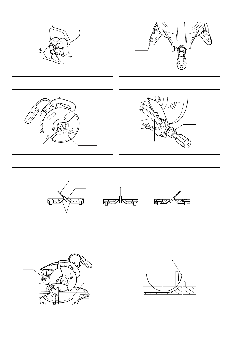
❏ When using the kerf block, always cut at the same mitre angle. When changing the mitre angle,
use other kerf blocks.
❏ Lors de l’utilisation du plateau de dÝcoupe, effectuez toujours la coupe au même angle de coupe.
Lorsque vous changez l’angle de coupe, utilisez d’autres plateaux de dÝcoupe.
❏ Bei Verwendung der Einlegeplatte immer mit demselben Gehrungswinkel schneiden. Bei einer
Änderung des Gehrungswinkels sind andere Einlegeplatten zu verwenden.
❏ Usando il blocco di taglio, tagliare sempre allo stesso angolo di taglio a quartabuono. Per cambiare
l’angolo di taglio a quartabuono, usare altri blocchi di taglio.
❏ Zaag altijd met dezelfde verstekhoek wanneer u het zaagsnedeblok gebruikt. Wanneer u de ver-
stekhoek verandert, moet u een ander zaagsnedeblok gebruiken.
❏ Cuando utilice la placa de corte, corte siempre con el mismo Üngulo de inglete. Cuando cambie el
Üngulo de inglete, utilice otras placas de corte.
❏ Quando utilize o bloco de corte, corte sempre com o mesmo ângulo de esquadria. Quando mudar
o ângulo de esquadria, utilize outros blocos de corte.
❏ Når indlægspladen anvendes, skal der altid skæres med samme geringsvinkel. Hvis geringsvin-
klen ændres, skal der anvendes en anden indlægsplade.
❏ Såga alltid med samma geringsvinkel när spårklossen används. Använd andra spårklossar om du
ändrar geringsvinkeln.
❏ Ved bruk av skjæreplaten, må det alltid skjæres i samme gjæringsvinkel. Når gjæringsvinkelen
endres, må det brukes andre skjæreplater.
❏ Kun käytät uurroslohkoa, sahaa aina samalla kulmalla. Kun vaihdat jiirisahauskulmaa, käytä toisia
uurroslohkoja.
❏ ταν χρησιµοποιείτε το µπλοκ εγκοπήσ, πάντοτε να κβετε µε την ίδια γωνία κεφαλήσ.
9
Page 10

ENGLISH
Explanation of general view
1 Stopper pin
2Bolt
3 Blade guard
4 Knob
5 Kerf board
6 Saw blade
7 Blade teeth
8 Left bevel cut
9 Straight cut
10 Right bevel cut
11 Adjusting bolt
12 Turn base
13 Top surface of turn base
14 Periphery of blade
15 Guide fence
16 Adjusting screw
17 Stopper arm
18 Lock lever
19 Grip
20 Pointer
21 Miter scale
22 Lever
23 Arm
24 Bevel scale
25 Lock-off button
26 Switch trigger
SPECIFICATIONS
Model LS1013F
Blade diameter ......................................................................................................................................... 250 – 260 mm
Hole diameter .....................................................European countries: 30 mm, other than European countries: 25.4 mm
Max. cutting capacities (H xW)
Miter angle
0° 50 mm x 305 mm 91 mm x 305 mm 31 mm x 305 mm
45° (left and right) 50 mm x 215 mm 91 mm x 215 mm 31 mm x 215 mm
52° (right) – 91 mm x 185 mm –
–1
No load speed (min
Dimensions (L x W x H) ..................................................................................................... 715 mm x 520 mm x 625 mm
Net weight ..................................................................................................................................... .......................21 .0 kg
• Due to our continuing program of research and development, the specifications herein are subject to change
without notice.
• Note: Specifications may differ from country to country.
Intended use
The tool is intended for accurate straight and miter cutting in wood. With appropriate saw blades, aluminum can
also be sawed.
) ............................................................................................................................................ 3,700
27 Handle
28 Light
29 Light switch
30 Socket wrench
31 Wrench holder
32 Center cover
33 Hex bolt
34 Blade case
35 Arrow
36 Shaft lock
37 Inner flange
38 Spindle
39 Ring
40 Outer flange
41 Hex bolt (left handed)
42 Dust nozzle
43 Dust bag
44 Fastener
45 Sub-fence
46 Sub-fence R
47 Screws
48 Vise arm
49 Vise rod
50 Clamp screw
51 Support
52 Turn base
Bevel angle
45° (left) 0° 45° (right)
Power supply
The tool should be connected only to a power supply of
the same voltage as indicated on the nameplate, and can
only be operated on single-phase AC supply. They are
double-insulated in accordance with European Standard
and can, therefore, also be used from sockets without
earth wire.
Safety hints
For your own safety, please refer to the enclosed safety
instructions.
53 Vise plate
54 Vise nut
55 Vise knob
56 Holder
57 Spacer block
58 Vise
59 Aluminum extrusion
60 Cut grooves with blade
61 Hex bolts
62 Triangular rule
63 Screw
64 Arm holder
65 Right 45° bevel angle
adjusting bolt
66 Left 45° bevel angle
adjusting bolt
67 Hex lock nut
68 Kerf block
69 Pull out
70 Push
71 Lamp box
72 Fluorescent tube
73 Limit mark
74 Brush holder cap
75 Screwdriver
10
Page 11

ADDITIONAL SAFETY RULES FOR TOOL
1. Wear eye protection.
2. Keep hands out of path of saw blade. Avoid con-
tact with any coasting blade. It can still cause severe
injury.
3. Do not operate saw without guards in place.
Check blade guard for proper closing before
each use. Do not operate saw if blade guard
does not move freely and close instantly. Never
clamp or tie the blade guard into the open position.
4. Do not perform any operation freehand. The
workpiece must be secured firmly against the turn
base and guide fence with the vise during all operations. Never use your hand to secure the workpiece.
5. Never reach around saw blade.
6. Turn off tool and wait for saw blade to stop
before moving workpiece or changing settings.
7. Unplug tool before changing blade or servicing.
8. Always secure all moving portions before carrying the tool.
9. Stopper pin which locks the cutter head down is
for carrying and storage purposes only and not
for any cutting operations.
10. Don’t use the tool in the presence of flammable liq-
uids or gases.
11. Check the blade carefully for cracks or damage
before operation.
Replace cracked or damaged blade immediately.
12. Use only flanges specified for this tool.
13. Be careful not to damage the arbor, flanges (espe-
cially the installing surface) or bolt. Damage to these
parts could result in blade breakage.
14. Make sure that the turn base is properly secured so
it will not move during operation.
15. For your safety, remove the chips, small pieces, etc.
from the table top before operation.
16. Avoid cutting nails. Inspect for and remove all nails
from the workpiece before operation.
17. Make sure the shaft lock is released before the
switch is turned on.
18. Be sure that the blade does not contact the turn
base in the lowest position.
19. Hold the handle firmly. Be aware that the saw moves
up or down slightly during start-up and stopping.
20. Make sure the blade is not contacting the workpiece
before the switch is turned on.
21. Before using the tool on an actual workpiece, let it
run for a while. Watch for vibration or wobbling that
could indicate poor installation or a poorly balanced
blade.
22. Wait until the blade attains full speed before cutting.
23. Stop operation immediately if you notice anything
abnormal.
24. Do not attempt to lock the trigger in the on position.
25. Be alert at all times, especially during repetitive,
monotonous operations. Don’t be lulled into a false
sense of security. Blades are extremely unforgiving.
26. Always use accessories recommended in this manual. Use of improper accessories such as abrasive
wheels may cause an injury.
27. Do not use the saw to cut other than aluminum,
wood or similar materials.
28. Connect miter saws to a dust collecting device
when sawing.
ENB034-2
29. Select saw blades in relation to the material to be
cut.
30. Take care when slotting.
31. Replace the kerf board when worn.
SAVE THESE INSTRUCTIONS
INSTALLATION
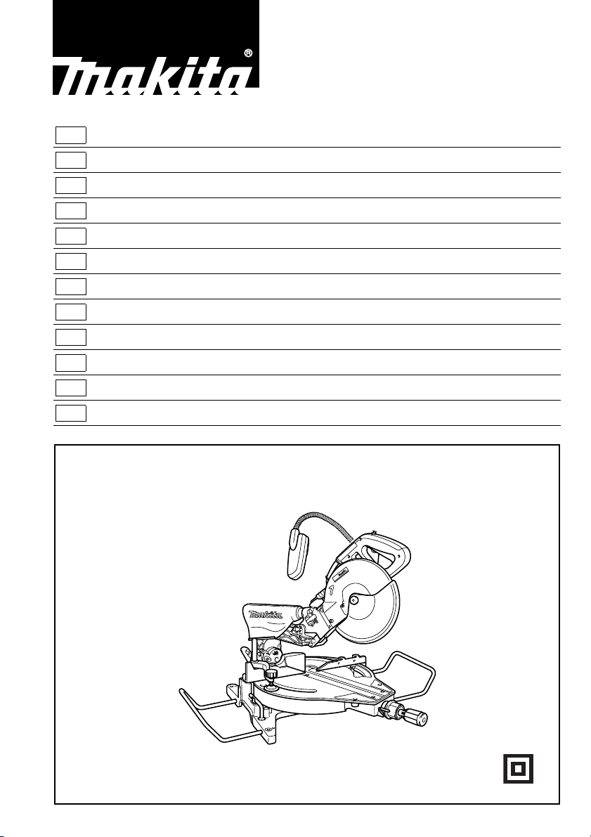
Bench mounting
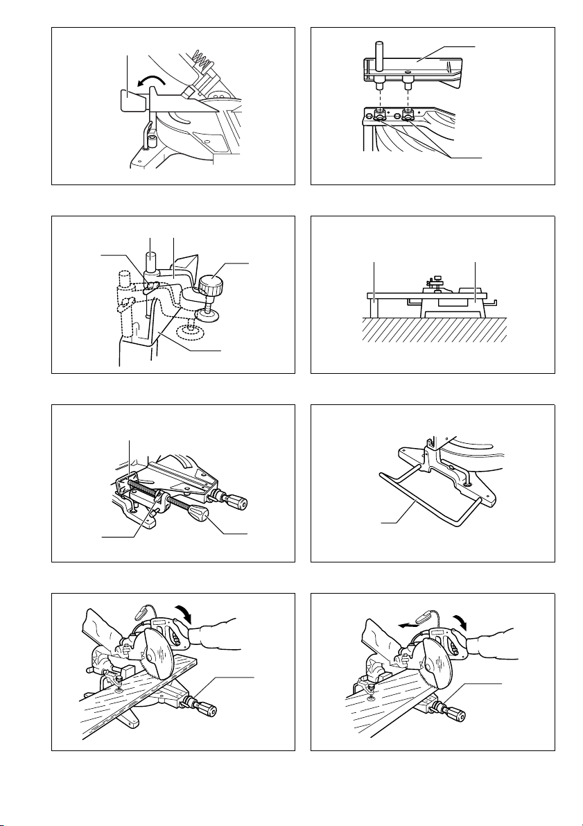
When the tool is shipped, the handle is locked in the lowered position by the stopper pin. Release the stopper pin
by lowering the handle slightly and pulling the stopper
pin. (Fig. 1)
This tool should be bolted with four bolts to a level and
stable surface using the bolt holes provided in the tool’s
base. This will help prevent tipping and possible injury.
(Fig. 2)
FUNCTIONAL DESCRIPTION
CAUTION:
• Always be sure that the tool is switched off and
unplugged before adjusting or checking function on the
tool.
Blade guard (Fig. 3)
When lowering the handle, the blade guard rises automatically. The blade guard returns to its original position
when the cut is completed and the handle is raised.
NEVER DEFEAT OR REMOVE THE BLADE GUARD.
In the interest of your personal safety, always maintain
the blade guard in good condition. Any irregular operation of the blade guard should be corrected immediately.
NEVER USE THE TOOL WITH A FAULTY BLADE
GUARD.
If the see-through blade guard becomes dirty, or sawdust
adheres to it in such a way that the blade and/or workpiece is no longer easily visible, unplug the saw and
clean the guard carefully with a damp cloth. Do not use
solvents or any petroleum-based cleaners on the plastic
guard.
Positioning kerf board (Fig. 4 & 5)
This tool is provided with the kerf boards in the turn base.
The kerf boards are factory adjusted so that the saw
blade does not contact the kerf boards. Before use,
adjust the kerf boards as follows:
First, unplug the tool. Loosen all the screws (2 each on
left and right) securing the kerf boards. Re-tighten them
to the extent that the kerf boards can be easily moved by
hand. Loosen the knob which secures the slide poles.
Pull the carriage toward you fully and lower the handle.
Adjust the kerf boards so that the kerf boards just contact
the side of blade teeth slightly. Tighten the front screws
(do not tighten firmly). Push the carriage toward the
guide fence fully and adjust the kerf boards so that the
kerf boards just contact the sides of blade teeth slightly.
Tighten the rear screws (do not tighten firmly). After
adjusting the kerf boards, raise the handle. Then tighten
all the screws securely.
CAUTION:
After changing the bevel angle, always readjust the kerf
boards as described above.
11
Page 12

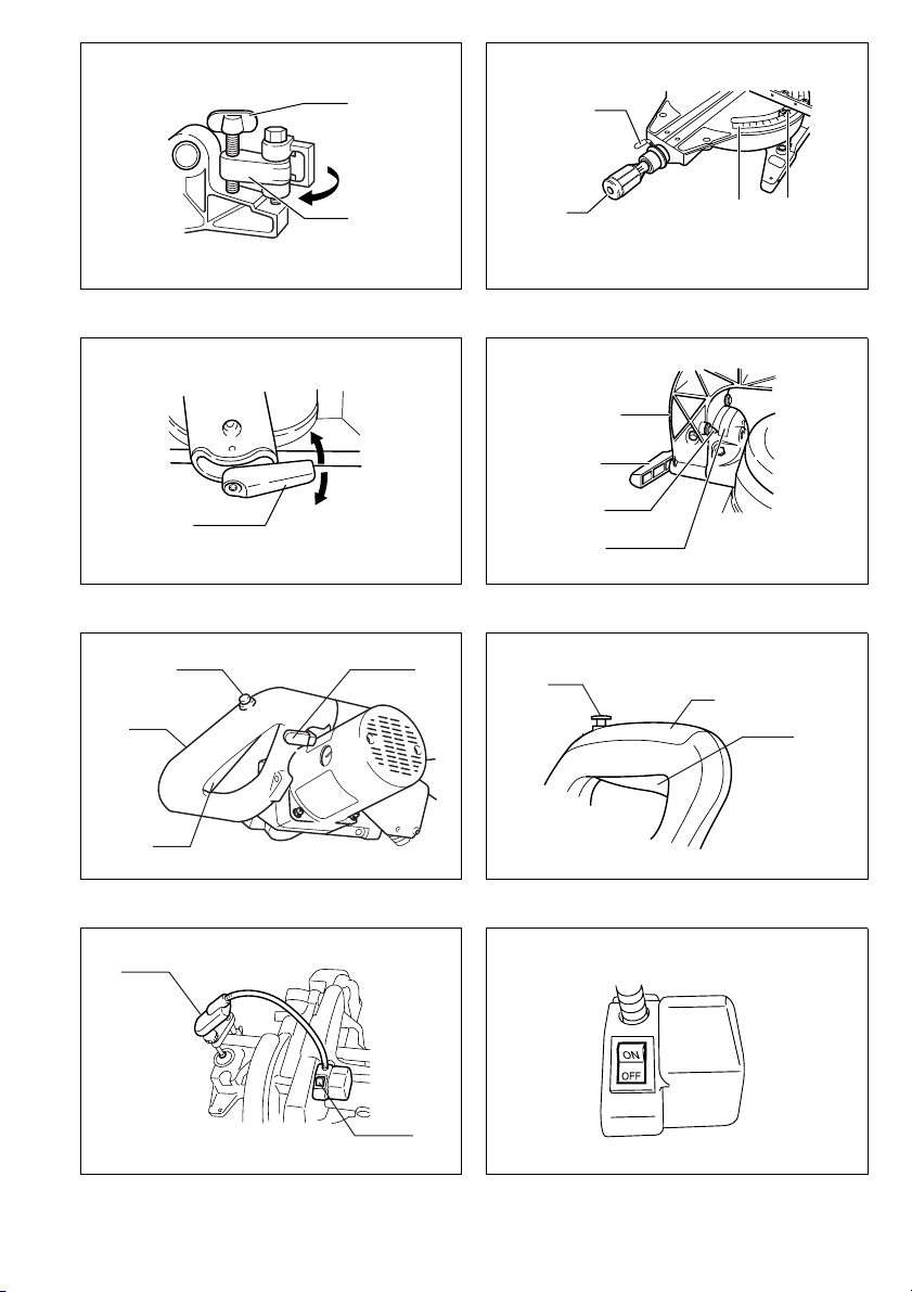
Maintaining maximum cutting capacity
(Fig. 6 & 7)
Unplug the tool before any adjustment is attempted. This
tool is factory adjusted to provide the max. cutting capacity for a 255mm saw blade.
When the diameter of the blade has been reduced due to
sharpening, adjust the lower limit position of the blade as
follows:
Push the carriage toward the guide fence fully and lower
the handle completely. Use the socket wrench to turn the
adjusting bolt until the periphery of the blade extends
slightly below the top surface of the turn base at the point
where the front face of the guide fence meets the top surface of the turn base. With the tool unplugged, rotate the
blade by hand while holding the handle all the way down
to be sure that the blade does not contact any part of the
lower base. Re-adjust slightly, if necessary.
CAUTION:
After installing a new blade, always be sure that the blade
does not contact any part of the lower base when the
handle is lowered completely. Always do this with the tool
unplugged.
Stopper arm (Fig. 8)
The lower limit position of the blade can be easily
adjusted with the stopper arm. To adjust it, rotate the
stopper arm in the direction of the arrow as shown in the
figure. Adjust the adjusting screw so that the blade stops
at the desired position when lowering the handle fully.
Positioning for adjusting the miter angle (Fig. 9)
Loosen the grip by turning counterclockwise. Turn the
turn base while pressing down the lock pin. When you
have moved the grip to the position where the pointer
indicates the desired angle on the miter scale, securely
tighten the grip clockwise.
CAUTION:
• When turning the turn base, be sure to raise the handle
fully.
• After changing the miter angle, always secure the turn
base by tightening the grip firmly.
Positioning for adjusting the bevel angle
(Fig. 10 & 11)
To adjust the bevel angle, loosen the lever at the rear of
the tool. Unlock the arm by pushing the handle rather
firmly in the direction that you intend to tilt the saw blade.
Tilt the saw blade until the pointer points to the desired
angle on the bevel scale. Tighten the lever to secure the
arm.
CAUTION:
• When tilting the saw blade, be sure to raise the handle
fully.
• After changing the bevel angle, always secure the arm
by tightening the lever clockwise.
• When changing bevel angles, be sure to position the
kerf boards appropriately as explained in the “Position-
ing kerf boards” section.
Switch action
CAUTION:
• Before plugging in the tool, always check to see that
the switch trigger actuates properly and returns to the
“OFF” position when released.
• When not using the tool, remove the lock-off button and
store it in a secure place. This prevents unauthorized
operation.
• Do not pull the switch trigger hard without pressing in
the lock-off button. This can cause switch breakage.
For European countries (Fig. 12)
To prevent the trigger from being accidentally pulled, a
lock-off button is provided. To start the tool, push the
lever to the left, press in the lock-off button and then pull
the switch trigger. Release the switch trigger to stop.
For all countries other than European countries
(Fig. 13)
To prevent the switch trigger from being accidentally
pulled, a lock-off button is provided. To start the tool,
press in the lock-off button and pull the switch trigger.
Release the switch trigger to stop.
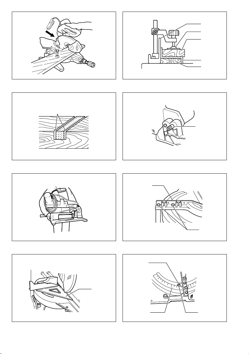
Lighting up the lamps (Fig. 14 & 15)
CAUTION:
• This is not a rainproof light. Do not wash the light in
water or use it in a rain or a wet area. Such a conduct
can cause an electric shock and fume.
• Do not touch the lens of the light, as it is very hot while
it is lighted or shortly after it is turned off. This may
cause a burn to a human body.
• Do not apply impact to the light, which may cause damage or shorted service time to it.
• Do not keep casting the beam of the light to your eyes.
This can cause your eyes to be hurt.
• Do not cover the light with clothes, carton, cardboard or
similar objects while it is lighted, which can cause a fire
or an ignition.
Push the upper position of the switch for turning on the
light and the lower position for off.
Move the light to shift an area of lighting.
NOTE:
• Use a dry cloth to wipe the dirt off the lens of lamp. Be
careful not to scratch the lens of light, or it may lower
the illumination.
ASSEMBLY
CAUTION:
• Always be sure that the tool is switched off and
unplugged before carrying out any work on the tool.
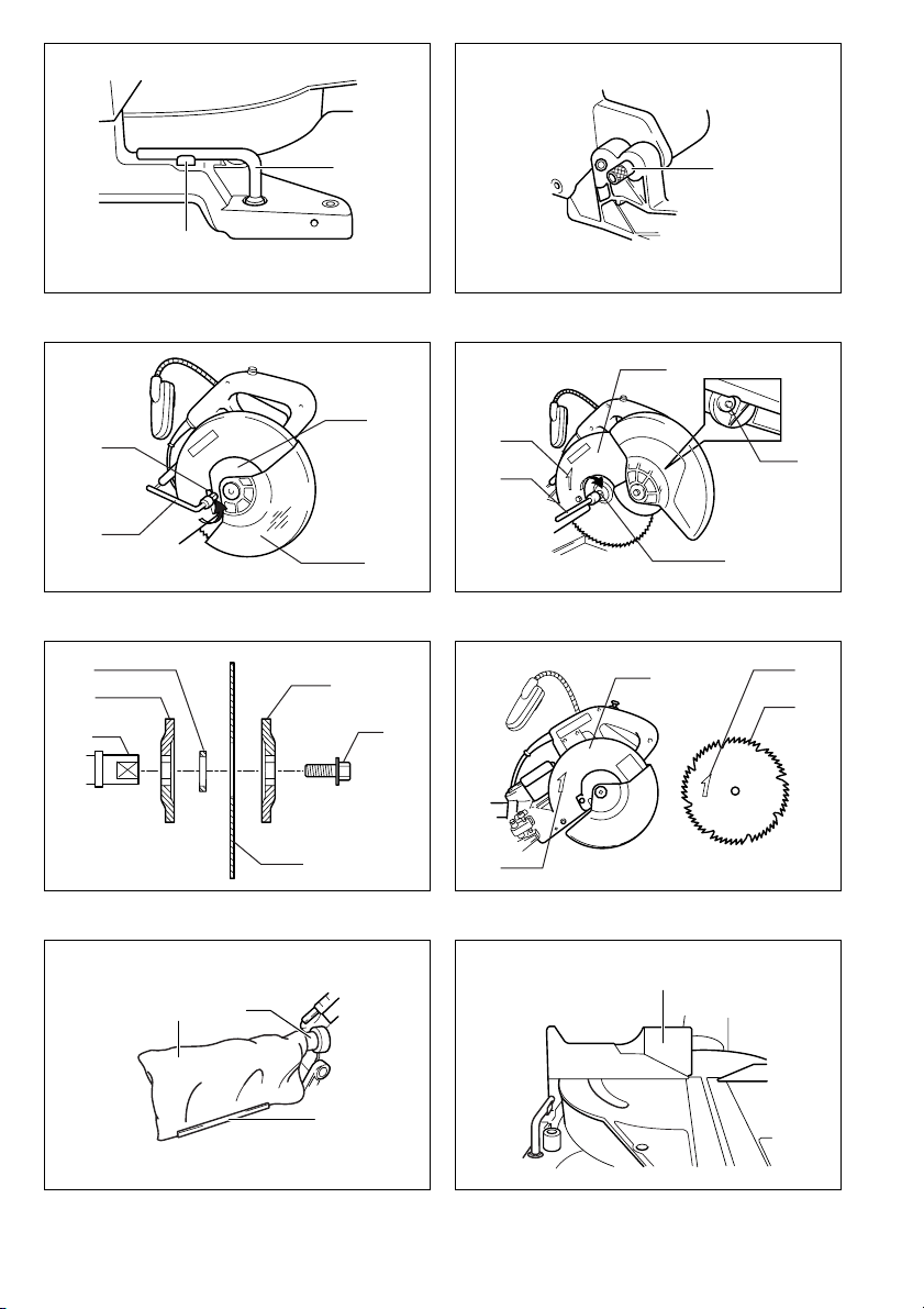
Socket wrench storage (Fig. 16)
The socket wrench is stored as shown in the figure.
When using the socket wrench, pull it out of the wrench
holder. After using the socket wrench, return it to the
wrench holder.
12
Page 13

Installing or removing saw blade
CAUTION:
• Always be sure that the tool is switched off and
unplugged before installing or removing the blade.
• Use only the Makita socket wrench provided to install
or remove the blade. Failure to do so may result in overtightening or insufficient tightening of the hex bolt. This
could cause a personal injury.
Lock the handle in the raised position by pushing in the
stopper pin. (Fig. 17)
To remove the blade, use the socket wrench to loosen the
hex bolt holding the center cover by turning it counterclockwise. Raise the blade guard and center cover.
(Fig. 18)
Press the shaft lock to lock the spindle and use the
socket wrench to loosen the hex bolt clockwise. Then
remove the hex bolt, outer flange and blade.
Mount the blade onto the spindle, making sure that the
direction of the arrow on the surface of the blade
matches the direction of the arrow on the blade case.
(Fig. 19)
For all countries other than European countries
CAUTION:
• The black ring 25 mm in outer diameter and the silver
ring 25.4 mm in outer diameter are factory-installed as
shown in the figure. When using a blade with 25 mm
hole diameter, replace the silver ring with the black ring.
Before mounting the blade onto the spindle, always be
sure that the correct ring for the arbor hole of the blade
you intend to use is installed between the inner and
outer flanges. (Fig. 20)
For European countries
CAUTION:
• The ring 30 mm in outer diameter is factory-installed
between the inner and outer flanges.
Install the outer flange and hex bolt, and then use the
socket wrench to tighten the hex bolt securely counter
clockwise while pressing the shaft lock. Then tighten the
hex bolt clockwise to secure the center cover. (Fig. 21)
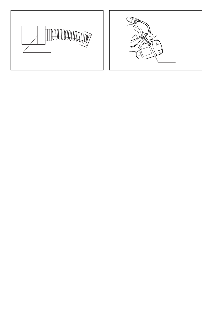
Dust bag
The use of the dust bag makes cutting operations clean
and dust collection easy. To attach the dust bag, insert
the dust nozzle into the dust spout on the blade case and
fit the bag’s entry port over the dust nozzle.
When the dust bag is about half full, remove the dust bag
from the tool and pull the fastener out. Empty the dust
bag of its contents, tapping it lightly so as to remove particles adhering to the insides which might hamper fur ther
collection.
NOTE:
• If you connect a vacuum cleaner to your saw, more effi-
(Fig. 22)
cient and cleaner operations can be performed.
Securing workpiece
WARNING:
• It is extremely important to always secure the workpiece properly and tightly with the vise. Failure to do so
can cause the tool to be damaged and/or the workpiece to be destroyed. PERSONAL INJURY MAY
ALSO RESULT. Also, after a cutting operation, DO NOT
raise the blade until the blade has come to a complete
stop.
Sub-fence
This tool is equipped with the sub-fence which should
ordinarily be positioned as shown in Fig. 23.
However, when performing left bevel cuts, set it to the left
position as shown in Fig. 24.
Sub-fence R (Accessory) (Fig. 25)
The sub-fence R should ordinarily be installed on the
right side of the guide fence. Insert the rods of the subfence R into the holes in the guide fence. Tighten the
screws to secure the sub-fence R.
CAUTION:
• When performing right bevel cuts, never use the subfence R. It will contact the blade or some part of the
tool, causing a serious injury to operator.
Vertical vise (Fig. 26 & 27)
The vertical vise can be installed in two positions on
either the left or right side of the guide fence or the base.
Insert the vise rod into the hole in the guide fence or the
base and tighten the screw on the back of the guide
fence to secure the vise rod.
Position the vise arm according to the thickness and
shape of the workpiece and secure the vise arm by tightening the screw. If the screw to secure the vise arm contacts the guide fence, install the screw on the opposite
side of vise arm. Make sure that no part of the tool contacts the vise when lowering the handle fully and pulling
or pushing the carriage all the way. If some part contacts
the vise, re-position the vise.
Press the workpiece flat against the guide fence and the
turn base. Position the workpiece at the desired cutting
position and secure it firmly by tightening the clamp
screw of the vise.
CAUTION:
• The workpiece must be secured firmly against the turn
base and guide fence with the vise during all operations.
Horizontal vise (optional accessory) (Fig. 28)
The horizontal vise can be installed in two positions on
either the left or right side of the base. When performing
15° or greater miter cuts, install the horizontal vise on the
side opposite the direction in which the turn base is to be
turned.
By flipping the vise nut to the left, the vise is released,
and rapidly moves in and out. To grip the workpiece, push
the vise knob forward until the vise plate contacts the
workpiece and flip the vise nut to the right. Then turn the
vise knob clockwise to secure the workpiece.
The maximum width of workpiece which can be secured
by the horizontal vise is 200 mm.
When installing the horizontal vise on the right side of the
base, also use the sub-fence R to secure the workpiece
more firmly. Refer to the “Sub-fence R” section described
on previously for installing the sub-fence R.
CAUTION:
• Always set the vice nut to the right fully when securing
the workpiece. Failure to do so may result in insufficient
securing of the workpiece. This could cause the workpiece to be thrown, cause damage to the blade subfence or cause the dangerous loss of control of the tool.
13
Page 14

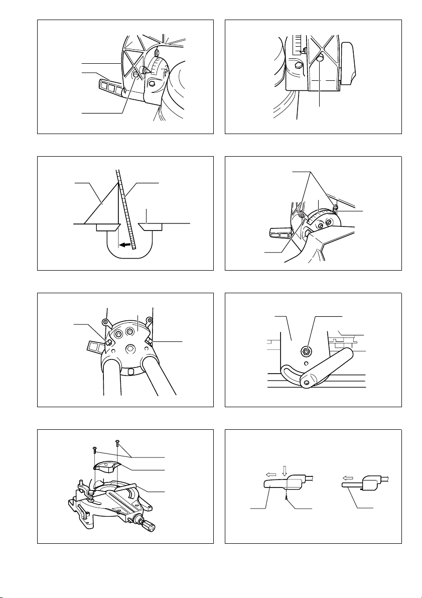
Holders (Fig. 29)
The holders can be installed on either side as a convenient means of holding workpieces horizontally. Slip the
holder rods into the holes in the base and adjust their
length according to the workpiece to be held. Then
tighten the holders securely with the screws.
OPERATION
CAUTION:
• Before use, be sure to release the handle from the lowered position by pulling the stopper pin.
• Make sure the blade is not contacting the workpiece,
etc. before the switch is turned on.
• Do not apply excessive pressure on the handle when
cutting. Too much force may result in overload of the
motor and/or decreased cutting efficiency.
• Gently press down the handle to perform the cut. If the
handle is pressed down with force or if lateral force is
applied, the blade will vibrate and leave a mark (saw
mark) in the workpiece and the precision of the cut will
be impaired.
• During a slide cut, gently push the carriage toward the
guide fence without stopping. If the carriage movement
is stopped during the cut, a mark will be left in the workpiece and the precision of the cut will be impaired.
1. Press cutting (cutting small workpieces)
(Fig. 30)
Workpieces up to 91 mm high and 70 mm wide can be
cut in the following way.
Push the carriage toward the guide fence fully and
tighten the knob to secure the carriage. Secure the workpiece with the vise. Switch on the tool and wait until the
blade attains full speed before lowering gently into the
cut. When the cut is completed, switch off the tool and
WAIT UNTIL THE BLADE HAS COME TO A COMPLETE STOP before returning the blade to its fully elevated position.
CAUTION:
• Firmly tighten the clamp screw on the turn base so that
the carriage will not move during operation. Insufficient
tightening may cause unexpected kickback of the
blade. Possible serious injury may result.
2. Slide (push) cutting (cutting wide workpieces)
(Fig. 31)
Workpieces up to 91 mm high and 305 mm wide can be
cut in the following way.
Loosen the knob counterclockwise so that the carriage
can slide freely. Secure the workpiece with the vise. Pull
the carriage toward you fully. Switch on the tool without
the blade making any contact and wait until the blade
attains full speed. Press down the handle and PUSH
THE CARRIAGE TOWARD THE GUIDE FENCE AND
THROUGH THE WORKPIECE. When the cut is completed, switch off the tool and WAIT UNTIL THE BLADE
HAS COME TO A COMPLETE STOP before returning
the blade to its fully elevated position.
CAUTION:
• Whenever performing the slide cut, FIRST PULL THE
CARRIAGE TOWARD YOU FULLY and press down the
handle to the fully lowered position, then PUSH THE
CARRIAGE TOWARD THE GUIDE FENCE. If you perform the slide cut without pulling the carriage fully or if
you perform the slide cut toward your direction, the
blade may kick back unexpectedly with the potential to
cause serious injury.
• Never perform the slide cut with the handle locked in
the lowered position by pressing the stopper pin.
3. Miter cutting
Refer to the previously covered “Positioning for adjusting
the miter angle”.
4. Bevel cut (Fig. 32)
Left and right 0°–45° bevel cuts can be performed. At a
left 45° bevel angle, workpieces up to 50 mm high and
305 mm wide can be cut. At a right 45° bevel angle,
workpieces up to 31 mm high and 305 mm wide can be
cut.
Loosen the lever and tilt the saw blade to set the bevel
angle. Be sure to re-tighten the lever firmly to secure the
selected bevel angle safely. Secure the workpiece with a
vise. Switch on the tool and wait until the blade attains
full speed. Then gently lower the handle to the fully lowered position while applying pressure in parallel with the
blade and PUSH THE CARRIAGE TOWARD THE
GUIDE FENCE TO CUT THE WORKPIECE. When the
cut is completed, switch off the tool and WAIT UNTIL
THE BLADE HAS COME TO A COMPLETE STOP
before returning the blade to its fully elevated position.
CAUTION:
• During a bevel cut, it may create a condition whereby
the piece cut off will come to rest against the side of the
blade. If the blade is raised while the blade is still rotating, this piece may be caught by the blade, causing
fragments to be scattered which is dangerous. The
blade should be raised ONLY after the blade has come
to a complete stop.
• When pressing down the handle, apply pressure in parallel with the blade. If a force is applied perpendicularly
to the turn base or if the pressure direction is changed
during a cut, the precision of the cut will be impaired.
5. Compound cutting
Compound cutting is the process in which a bevel angle
is made at the same time in which a miter angle is being
cut on a workpiece. Compound cutting can be performed
at angle shown in the table.
Miter angle Bevel angle
Left 0°–47°
and Right 0°–40°
Right 52°
At the miter angle of left and right 45° and bevel angle of
left 45°, workpieces up to 50 mm high and 215 mm wide
can be cut.
At the miter angle of left and right 45° and bevel angle of
right 45°, workpieces up to 31 mm high and 215 mm
wide can be cut.
When performing compound cutting, refer to “Press cutting”, “Slide cutting”, “Miter cutting” and “Bevel cut” explanations.
Left and Right 0°–45°
Left 0°–40°
and Right 0°–45°
14
Page 15

6. Cutting aluminum extrusion
When securing aluminum extrusions, use spacer blocks
or pieces of scrap as shown in Fig. 33 to prevent deformation of the aluminum. Use a cutting lubricant when
cutting the aluminum extrusion to prevent buildup of the
aluminum material on the blade.
CAUTION:
• Never attempt to cut thick or round aluminum extrusions. Thick aluminum extrusions may come loose during operation and round aluminum extrusions cannot
be secured firmly with this tool.
7. Groove cutting (Fig. 34)
A dado type cut can be made by proceeding as follows:
Adjust the lower limit position of the blade using the
adjusting screw and the stopper arm to limit the cutting
depth of the blade. Refer to “Stopper arm” section
described previously.
After adjusting the lower limit position of the blade, cut
parallel grooves across the width of the workpiece using
a slide (push) cut as shown in the figure. Then remove
the workpiece material between the grooves with a
chisel. Do not attempt to perform this type of cut using
wide (thick) blades or with a dado blade. Possible loss of
control and injury may result.
CAUTION:
• Be sure to return the stopper arm to the original position when performing other than groove cutting.
Carrying tool
Make sure that the tool is unplugged. Secure the blade at
0° bevel angle and the turn base at right miter angle fully.
Secure the slide poles after pulling the carriage toward
you fully. Lower the handle fully and lock it in the lowered
position by pushing in the stopper pin. (Fig. 35)
Carry the tool by holding both sides of the tool base as
shown in the figure. If you remove the holders, dust bag,
etc., you can carry the tool more easily. (Fig. 36)
CAUTION:
• Always secure all moving portions before carrying the
tool.
MAINTENANCE
CAUTION:
• Always be sure that the tool is switched off and
unplugged before attempting to perform inspection or
maintenance.
Adjusting the cutting angle
This tool is carefully adjusted and aligned at the factory,
but rough handling may have affected the alignment. If
your tool is not aligned properly, perform the following:
1. Miter angle
Push the carriage toward the guide fence and tighten the
knob to secure the carriage.
Loosen the grip which secures the turn base. Turn the
turn base so that the pointer points 0° on the miter scale.
Then turn the turn base slightly clockwise and counterclockwise to seat the turn base in the 0° miter notch.
(Leave as it is if the pointer does not point 0°.) Loosen
the hex bolts securing the guide fence using the socket
wrench. (Fig. 37)
Lower the handle fully and lock it in the lowered position
by pushing in the lock pin. Square the side of the blade
with the face of the guide fence using a triangular rule,
try-square, etc. Then securely tighten the hex bolts on
the guide fence in the order from the left side. (Fig. 38)
Make sure that the pointer indicates 0° on the miter
scale. If the pointer does not indicate 0°, loosen the
screw securing the pointer and adjust the pointer.
(Fig. 39)
2. Bevel angle
1) 0° bevel angle
Push the carriage toward the guide fence and
tighten the knob to secure the slide poles. Lower the
handle fully and lock it in the lowered position by
pushing in the lock pin. Loosen the lever at the rear
of the tool. Make sure that the arm is locked.
(Fig. 40)
Turn the hex bolt on the left side of the arm two or
three revolutions counterclockwise. Turn the hex bolt
on the right side of the arm two or three revolutions
counterclockwise to tilt the blade to the left. (Fig. 41)
Carefully square the side of the blade with the top
surface of the turn base using the triangular rule, trysquare, etc. by turning the hex bolt on the right side
of the arm clockwise. Turn the hex bolt on the left
side of the arm clockwise as far as it will go. Then
tighten the lever securely. (Fig. 42)
Make sure that the two pointers on the arm point to
each 0° on the bevel scale on the arm holder. If they
do not point to 0°, loosen the screws which secure
the pointers and adjust them so that they will point to
0°. (Fig. 43)
2) 45° bevel angle (Fig. 44)
Adjust the 45° bevel angle only after performing 0°
bevel angle adjustment. To adjust left 45° bevel
angle, loosen the lever and tilt the blade 45° to the
left. Make sure that the pointer on the arm holder
points to 45° on the bevel scale on the arm holder. If
the pointer does not point to 45°, turn the left 45°
bevel angle adjusting bolt on the side of the arm
holder until the pointer points to 45°. To adjust right
45° bevel angle, perform the same procedure
described above.
Adjusting for smooth beveling action (Fig. 45)
The hex lock nut holding together the arm and arm
holder has been factory adjusted to assure smooth beveling action and to guarantee precise cutting. Do not
tamper with it. Should looseness develop at the arm and
arm holder connection, tighten the hex lock nut using a
wrench.
15
Page 16

Kerf block (optional accessory) (Fig.46)
CAUTION:
• When using the kerf block, always cut at the same miter
angle.
• When changing the miter angle, use other kerf blocks.
• When performing bevel cuts, never use the kerf blocks.
Failure to do so splits the block, causing a serious injury
to operator.
When you use the kerf block at 90° cutting, you can splinter-free cut in workpiece on the side of the guide fence
(height of the workpiece is up to 35 mm). Install the kerf
block onto the guide fence by means of the two screws.
(Adjust the guide fence and the kerf block so that they
contact their faces. Then tighten the screws securely.)
Replacing fluorescent tube (Fig. 47)
CAUTION:
• Always be sure that the tool is switched off and
unplugged before replacing the fluorescent tube.
• Do not apply force, impact or scratch to a fluorescent
tube, which can cause a glass of the fluorescent tube to
be broken resulting in a injury to you or your bystanders.
• Leave the florescent tube for a while immediately after
a use of it and then replace it. If not, you may burn
yourself.
Remove screws, which secure Lamp box for the light.
Pull out the Lamp box keeping pushing lightly the upper
position of it as illustrated on Fig. 47.
Pull out the fluorescent tube and then replace it with
Makita original new one.
Replacing carbon brushes (Fig. 48 & 49)
Remove and check the carbon brushes regularly.
Replace when they wear down to the limit mark. Keep
the carbon brushes clean and free to slip in the holders.
Both carbon brushes should be replaced at the same
time. Use only identical carbon brushes.
Use a screwdriver to remove the brush holder caps. Take
out the worn carbon brushes, insert the new ones and
secure the brush holder caps.
After use
• After use, wipe off chips and dust adhering to the tool
with a cloth or the like. Keep the blade guard clean
according to the directions in the previously covered
section titled “Blade guard”. Lubricate the sliding portions with tool oil to prevent rust.
• When storing the tool, pull the carriage toward you fully
so that the slide pole is thoroughly inserted into the turn
base.
To maintain product SAFETY and RELIABILITY, repairs,
any other maintenance or adjustment should be performed by Makita Authorized Service Centers, always
using Makita replacement parts.
ACCESSORIES
CAUTION:
• These accessories or attachments are recommended
for use with your Makita tool specified in this manual.
The use of any other accessories or attachments might
present a risk of injury to persons. Only use accessory
or attachment for its stated purpose.
If you need any assistance for more details regarding
these accessories, ask your local Makita service center.
• Carbide-tipped saw blades
• Dust bag
• Sub-fence R
• Elbow
• Vise assembly (Horizontal vise)
• Triangular rule
• Vertical vise
• Lock-off button (2 pcs.)
• Socket wrench 13
• Kerf block
• Fluorescent tube
16
Page 17

NEDERLANDS
Verklaring van algemene gegevens
1 Aanslagpen
2Bout
3 Veiligheidskap
4 Knop
5 Zaagsnedeplaat
6 Zaagblad
7 Zaagbladtanden
8 Linkse verstek snede
9 Rechte snede
10 Rechtse verstek snede
11 Stelbout
12 Draaibaar voetstuk
13 Bovenvlak van draaibaar
voetstuk
14 Omtrek van zaagblad
15 Geleider
16 Stelschroef
17 Aanslagarm
18 Ingedrukt houdt
19 Greep
20 Wijzer
21 Verstekschaal
22 Hendel
23 Arm
24 Schuine-hoek schaal
25 Ontgrendelknop
26 Trekschakelaar
TECHNISCHE GEGEVENS
Model LS1013F
Diameter zaagblad .................................................................................................................................... 250 – 260 mm
Diameter zaagbladgat ..........................................................Europese landen: 30 mm, niet-Europese landen: 25,4 mm
Max. zaagcapaciteiten (H x B)
Verstekhoek
0° 50 mm x 305 mm 91 mm x 305 mm 31 mm x 305 mm
45° (links en rechts) 50mmx215mm 91mmx215mm 31mmx215mm
52° (rechts) – 91 mm x 185 mm –
–1
Toerental onbelast (min
Afmetingen (L x B x H) .......................................................................................................715 mm x 520 mm x 625 mm
Netto gewicht........................................................................................................................................................... 21 kg
• In verband met ononderbroken research en ontwikke-
ling, behouden wij ons het recht voor de bovenstaande
technische gegevens zonder voorafgaande kennisgeving te wijzigen.
• Opmerking: De technische gegevens kunnen van land
tot land verschillen.
Doeleinden van gebruik
Dit gereedschap is bedoeld voor nauwkeurig recht zagen
en verstekzagen in hout. Bij gebruik van de geschikte
zaagbladen kan ook aluminium worden gezaagd.
)....................................................................................................................................... 3 700
27 Handvat
28 Lamp
29 Lampschakelaar
30 Dopsleutel
31 Sleutelhouder
32 Middenkap
33 Zeskante bout
34 Zaagbladkast
35 Pijltje
36 Asvergrendeling
37 Binnenflens
38 As
39 Ring
40 Buitenflens
41 Zeskantbout
(linkse schroefdraad)
42 Stofuitlaat
43 Stofzak
44 Sluitstrip
45 Hulpgeleider
46 Hulpgeleider R
47 Schroeven
48 Spanschroefarm
49 Spanschroefstang
50 Klemschroef
51 Steun
52 Draaibaar voetstuk
Schuine hoek
45° (links) 0° 45° (rechts)
Stroomvoorziening
Het gereedschap mag alleen worden aangesloten op
een stroombron van hetzelfde voltage als aangegeven op
de naamplaat, en kan alleen op enkel-fase wisselstroom
worden gebruikt. Het gereedschap is dubbel-geïsoleerd
volgens de Europese standaard en kan derhalve ook op
een niet-geaard stopcontact worden gebruikt.
Veiligheidswenken
Voor uw veiligheid dient u de bijgevoegde Veiligheidsvoorschriften nauwkeurig op te volgen.
53 Spanschroefplaat
54 Spanschroefmoer
55 Spanschroefknop
56 Houder
57 Vulblok
58 Spanschroef
59 Aluminium werkstuk
60 Groeven zagen met
het zaagblad
61 Zeskante bout
62 Driehoeksliniaal
63 Schroef
64 Armhouder
65 Stelbout voor rechtse 45°
schuine hoek
66 Stelbout voor linkse 45°
schuine hoek
67 Zeskant borgmoer
68 Zaagsnedeblok
69 Naar buiten trekken
70 Drukken
71 Lampkast
72 TL-buis
73 Limietmerkstreep
74 Borstelhouderdop
75 Schroevendraaier
41
Page 18

AANVULLENDE
VEILIGHEIDSVOORSCHRIFTEN VOOR HET
GEREEDSCHAP
1. Draag oogbescherming.
2. Houd uw handen uit de buurt van het zaagblad.
Raak het freewheelende zaagblad niet aan, aangezien dit nog ernstige verwonding kan veroorzaken.
3. Gebruik de zaag niet zonder dat de veiligheidskappen zijn aangebracht.
Controleer vóór elk gebruik of de veiligheidskap
goed sluit. Gebruik de zaag niet indien de veiligheidskap niet goed beweegt en niet snel over het
zaagblad sluit. Klem of bind de veiligheidskap
nooit in de geopende stand vast.
4. Zaag nooit met het werkstuk in uw hand. Gebruik
altijd de spanschroef om het werkstuk goed vast te
zetten op het draaibaar voetstuk en tegen de geleider. Gebruik nooit uw hand om het werkstuk tijdens
het zagen vast te houden.
5. Reik nooit in de nabijheid van het zaagblad.
6. Schakel het gereedschap uit en wacht totdat het
zaagblad volledig tot stilstand is gekomen alvorens het werkstuk te verwijderen of instellingen
te veranderen.
7. Trek de stekker uit het stopcontact alvorens het
zaagblad te verwisselen of onderhoud aan het
gereedschap uit te voeren.
8. Zet altijd alle bewegende onderdelen vast alvorens het gereedschap te dragen.
9. De aanslagpen die de zaagkop in de omlaagpositie vergrendelt, wordt alleen gebruikt voor het
dragen en opbergen van het gereedschap en
niet voor zaagbedieningen.
10. Gebruik het gereedschap niet in de nabijheid van
ontvlambare gassen of vloeistoffen.
11. Controleer het zaagblad zorgvuldig op barsten of
beschadiging, alvorens het gereedschap te gebruiken.
Een gebarsten of beschadigd zaagblad dient onmiddellijk te worden vervangen.
12. Gebruik alleen flenzen die voor dit gereedschap zijn
bestemd.
13. Pas op dat u de as, de flenzen (vooral hun montagevlak) of de bout niet beschadigt. Beschadiging van
deze onderdelen kan zaagbladbreuk veroorzaken.
14. Zorg dat het draaibaar voetstuk goed vastgezet is,
zodat het tijdens het zagen niet kan bewegen.
15. Verwijder voor uw eigen veiligheid zaagafval, stukjes
hout e.d. van de werktafel alvorens te gaan zagen.
16. Vermijd het zagen op spijkers. Inspecteer het werkstuk en verwijder alle eventuele spijkers alvorens
met het zagen te beginnen.
17. Zet de asvergrendeling in de vrije stand alvorens de
trekschakelaar in te drukken.
18. Zorg ervoor dat het zaagblad in zijn laagste positie
niet in aanraking komt met het draaibaar voetstuk.
19. Houd het handvat stevig vast. Denk eraan dat de
zaag bij het starten en stoppen even op- en neergaat.
20. Zorg dat het zaagblad bij het inschakelen niet in con-
tact is met het werkstuk.
21. Laat het gereedschap een tijdje draaien alvorens het
op het werkstuk te gebruiken. Controleer op trillingen of schommelingen die op onjuiste installatie of
op een slecht gebalanceerd zaagblad kunnen wijzen.
22. Wacht totdat het zaagblad op volle toeren draait,
alvorens het werkstuk te zagen.
23. Stop onmiddellijk met zagen indien u iets abnor-
maals opmerkt.
24. Probeer niet om de trekschakelaar in de ingescha-
keld positie te vergrendelen.
25. Laat uw aandacht nooit verslappen, vooral niet wan-
neer het werk saai is en uit herhalingen bestaat.
Laat u niet door een vals gevoel van veiligheid misleiden, aangezien zaagbladen altijd uiterst gevaarlijk
zijn.
26. Gebruik uitsluitend de accessoires die in deze
gebruiksaanwijzing worden aanbevolen. Het gebruik
van ongeschikte accessoires, zoals slijpschijven,
kan verwonding veroorzaken.
27. Gebruik de zaag niet voor het zagen van andere
materialen dan aluminium, hout of soortgelijk
materiaal.
28. Sluit verstekzagen tijdens het zagen aan op een
stofvanginrichting.
29. Selecteer de zaagbladen in overeenstemming
met het te zagen materiaal.
30. Wees voorzichtig wanneer u gleuven zaagt.
31. Vervang de zaagsnedeplaat wanneer deze versleten is.
BEWAAR DEZE VOORSCHRIFTEN
INSTALLEREN
Het gereedschap op de werktafel monteren
Bij de verscheping uit de fabriek is het handvat door middel van de aanslagpen in de omlaagpositie vergrendeld.
Ontgrendel de aanslagpen door het handvat ietwat
omlaag te drukken en aan de aanslagpen te trekken.
(Fig. 1)
Dit gereedschap dient op een vlak en stabiel oppervlak
te worden gemonteerd door middel van vier bouten die u
vastdraait in de boutgaten in de voet van het gereedschap. Hierdoor wordt voorkomen dat het gereedschap
omkantelt en mogelijk verwondingen veroorzaakt.
(Fig. 2)
BESCHRIJVING VAN DE FUNCTIES
LET OP:
• Controleer altijd of het gereedschap is uitgeschakeld
en zijn stekker uit het stopcontact is verwijderd alvorens de functies op het gereedschap te controleren of
af te stellen.
42
Page 19

Veiligheidskap (Fig. 3)
Wanneer het handvat omlaag wordt gebracht, gaat de
veiligheidskap automatisch omhoog. De veiligheidskap
keert terug naar haar oorspronkelijke positie wanneer het
zagen is voltooid en het handvat omhoog wordt gebracht.
ZET DE VEILIGHEIDSKAP NOOIT VAST EN VERWIJDER NOOIT DE VEILIGHEIDSKAP OF DE VEER.
Voor uw persoonlijke veiligheid dient de veiligheidskap
altijd in goede staat te worden gehouden. Elke onregelmatigheid in de werking van de veiligheidskap dient
onmiddellijk te worden hersteld. GEBRUIK HET
GEREEDSCHAP NOOIT MET EEN DEFECTE VEILIGHEIDSKAP.
Als de doorzichtige veiligheidskap vuil is of met zaagsel
is bedekt zodat het zaagblad en/of het werkstuk niet
meer goed zichtbaar is, haal dan de stekker uit het stopcontact en maak de veiligheidskap met een bevochtigde
doek goed schoon. Gebruik voor het reinigen van de
plastic veiligheidskap nooit oplosmiddelen of benzinehoudende schoonmaakmiddelen.
Afstellen van de zaagsnedeplaten (Fig. 4 en 5)
Deze machine is voorzien van zaagsnede-platen in het
draaibaar voetstuk. De zaagsnede-platen zijn in de
fabriek zodanig afgesteld dat het zaagblad niet met de
zaagsnede-platen in aanraking komt. Stel de zaagsnedeplaten als volgt af, alvorens de machine in gebruik te
nemen:
Trek eerst de stekker van de machine uit het stopcontact.
Draai alle schroeven (2 aan de linkerzijde en 2 aan de
rechterzijde) waarmee de zaagsnede-platen zijn vastgemaakt los. Trek de schroeven weer aan zodanig dat de
zaagsnede-platen gemakkelijk met de hand kunnen worden bewogen. Draai de knop waarmee de glijstangen
zijn vastgemaakt los. Trek de slede helemaal naar u toe
en breng het handvat omlaag. Stel de positie van de
zaagsnede-platen zodanig af dat deze lichtjes in aanraking komen met de zijkanten van de zaagbladtanden.
Trek de voorste schroeven aan (niet te hard aantrekken).
Duw de slede zo ver mogelijk naar de geleider en stel de
positie van de zaagsnede-platen zodanig af dat deze
lichtjes in aanraking komen met de zijkanten van de
zaagbladtanden. Trek de achterste schroeven aan (niet
te hard aantrekken). Breng het handvat omhoog nadat
de zaagsnede-platen zijn afgesteld. Trek vervolgens alle
schroeven stevig aan.
LET OP:
Telkens nadat u de schuine hoek hebt gewijzigd, dient u
de zaagsnede-platen opnieuw af te stellen op de bovenstaande wijze.
Handhaven van de maximale zaagcapaciteit
(Fig.6 en7)
Trek de stekker van de machine uit het stopcontact alvorens afstellingen te maken. Deze machine is in de fabriek
ingesteld voor het leveren van maximale zaagcapaciteit
met een 255 mm zaagblad.
Wanneer de diameter van het zaagblad vanwege herhaald aanscherpen is geslonken, dient u de laagste positie van het zaagblad als volgt af te stellen:
Duw de slede zo ver mogelijk naar de geleider en breng
het handvat helemaal omlaag. Gebruik de dopsleutel en
verdraai de afstelbout totdat de omtrek van het zaagblad
een beetje onder het bovenvlak van het draaibaar voetstuk komt te zitten op het punt waar het voorvlak van de
geleider in aanraking komt met het bovenvlak van het
draaibaar voetstuk. Draai met de hand het zaagblad rond
(met de stekker uit het stopcontact!) terwijl u het handvat
volledig omlaag gedrukt houdt, en controleer of het zaagblad met geen enkel deel van het onderste voetstuk in
aanraking komt. Stel opnieuw een beetje af, indien nodig.
LET OP:
Na het installeren van een nieuw zaagblad, dient u altijd
te controleren of het zaagblad met geen enkel deel van
het onderste voetstuk in aanraking komt wanneer het
handvat volledig naar omlaag is gebracht. Trek voor deze
controle altijd de stekker van de machine uit het stopcontact.
Aanslagarm (Fig. 8)
Met de aanslagarm kunt u de laagste positie van het
zaagblad gemakkelijk instellen. Om in te stellen draait u
de aanslagarm in de richting van het pijltje zoals afgebeeld. Stel de stelschroef zodanig in dat het zaagblad bij
de gewenste positie stopt wanneer het handvat volledig
omlaag wordt gebracht.
Instellen van de verstekhoek (Fig.9)
Draai de handgreep naar links los. Verdraai het draaibaar
voetstuk terwijl u de borgpen ingedrukt houdt. Beweeg
de handgreep naar de positie waarbij de wijzer de
gewenste hoek op de verstekschaal aanwijst en draai
dan de handgreep weer stevig naar rechts vast.
LET OP:
• Voor het verdraaien van het draaibaar voetstuk dient u
het handvat volledig omhoog te brengen.
• Na het wijzigen van de verstekhoek, dient u het draaibaar voetstuk altijd vast te zetten door de greep goed
vast te draaien.
Instellen van de schuine hoek (Fig. 10 en 11)
Om de schuine hoek in te stellen, draait u de hendel aan
de achterzijde van het gereedschap los. Ontgrendel de
arm door het handvat tamelijk krachtig in de richting te
duwen waarin u het zaagblad wilt schuinzetten.
Kantel het zaagblad totdat de wijzer naar de gewenste
hoek op de schuine-hoek schaalverdeling wijst. Draai
daarna de hendel weer vast om de arm te vergrendelen.
LET OP:
• Wanneer u het zaagblad schuin zet, dient u het handvat volledig omhoog te brengen.
• Na het wijzigen van de schuine hoek, dient u de arm
altijd vast te zetten door de hendel naar rechts vast te
draaien.
• Na het wijzigen van de schuine hoek, dient u de
zaagsnedeplaten weer in de juiste positie te zetten volgens de aanwijzingen in de paragraaf “Afstellen van de
zaagsnedeplaten.”
43
Page 20

Werking van de schakelaar
LET OP:
• Alvorens de stekker in een stopcontact te steken, moet
u altijd controleren of de trekschakelaar goed werkt en
bij het loslaten naar de “UITGESCHAKELD” (OFF)
positie terugkeert.
• Verwijder de ontgrendelknop en bewaar deze op een
veilige plaats wanneer u het gereedschap niet gebruikt.
Hierdoor voorkomt u ongeoorloofd gebruik van het
gereedschap.
• Druk de trekschakelaar niet hard in zonder dat de ontgrendelknop is ingedrukt. Hierdoor kan de schakelaar
namelijk breken.
Voor Europese landen (Fig. 12)
Een ontgrendelknop is voorzien om te voorkomen dat de
trekschakelaar per ongeluk wordt ingedrukt. Om de hetgereedschap te starten, duw de hendel naar links, druk
de ontgrendelknop in en druk daarna de trekschakelaar
in. Om het gereedschap te stoppen, laat u de trekschakelaar los.
Voor alle niet-Europese landen (Fig. 13)
Een ontgrendelknop is voorzien om te voorkomen dat de
trekschakelaar per ongeluk wordt ingedrukt. Om het
gereedschap te starten, druk de ontgrendelknop in en
druk vervolgens de trekschakelaar in. Om het gereedschap te stoppen, laat u de trekschakelaar los.
Aanzetten van de lampen (Fig. 14 en 15)
LET OP:
• De lamp is niet waterdicht. Was de lamp niet in water
en gebruik hem niet in de regen of in een natte omgeving. Dit kan namelijk een elektrische schok en uitwaseming veroorzaken.
• Raak de lens van de lamp niet aan, aangezien deze tijdens of onmiddellijk na het gebruik uiterst heet is en
brandwonden kan veroorzaken.
• Stel de lamp niet bloot aan schokken of stoten, aangezien de lamp daardoor beschadigd kan raken of minder
lang zal meegaan.
• Richt de stralenbundel van de lamp niet langdurig naar
uw ogen. Dit kan namelijk oogletsel veroorzaken.
• Bedek de brandende lamp niet met een doek, karton of
soortgelijke voorwerpen. Dit kan namelijk brand of ontbranding veroorzaken.
Druk op het bovenste gedeelte van de schakelaar om de
lamp aan te zetten, en op het onderste gedeelte om de
lamp uit te doen.
Beweeg de lamp om de gewenste plek te verlichten.
OPMERKING:
• Gebruik een droge doek om vuil op de lens van de
lamp eraf te vegen. Pas op dat u geen krassen maakt
op de lens, omdat de verlichtingssterkte daardoor kan
verminderen.
INEENZETTEN
LET OP:
• Zorg altijd dat het gereedschap is uitgeschakeld en zijn
stekker uit het stopcontact is verwijderd alvorens enig
werk aan het gereedschap uit te voeren.
Opbergen van de dopsleutel (Fig. 16)
Berg de dopsleutel op zoals afgebeeld. Trek de dopsleutel uit de sleutelhouder wanneer u hem wilt gebruiken.
Breng hem na het gebruik weer aan in de sleutelhouder.
Installeren of verwijderen van het zaagblad
LET OP:
• Zorg altijd dat het gereedschap is uitgeschakeld en zijn
stekker uit het stopcontact is verwijderd alvorens het
zaagblad te installeren of te verwijderen.
• Gebruik voor het installeren of verwijderen van het
zaagblad uitsluitend de bijgeleverde Makita dopsleutel.
Doet u dit niet, dan kan de zeskante bout te vast of te
los worden aangedraaid, hetgeen persoonlijke verwonding kan veroorzaken.
Druk de aanslagpen naar binnen om het handvat in de
omhoogpositie te vergrendelen. (Fig. 17)
Gebruik de dopsleutel om de zeskante bout, die de middenkap op zijn plaats houdt, naar links los te draaien.
Breng de veiligheidskap en de middenkap omhoog.
(Fig.18)
Druk de asvergrendeling in om de as te vergrendelen en
draai met de dopsleutel de zeskante bout naar rechts los.
Verwijder vervolgens de zeskante bout, de buitenflens en
het zaagblad.
Om het zaagblad te installeren, monteert u het zaagblad
op de as, ervoor zorgend dat de pijlen op het zaagblad
en op de vaste besschermkap in dezelfde richting wijzen.
(Fig.19)
Voor alle niet-Europese landen
LET OP:
• De zwarte ring (25 mm buitendiameter) en de zilverring
(25,4 mm buitendiameter) zijn in de fabriek op de as
gemonteerd zoals afgebeeld. Bij gebruik van een zaagblad met een 25 mm asgatdiameter, dient u de zilverring door de zwarte ring te vervangen. Alvorens het
zaagblad op de as te monteren, moet u altijd controleren of de juiste ring, voor het asgat van het blad dat u
gaat gebruiken, tussen de binnenflens en buitenflens
op de as is gemonteerd. (Fig. 20)
Voor Europese landen
LET OP:
• De ring met een buitendiameter van 30 mm werd in de
fabriek tussen de binnenflens en buitenflens gemonteerd.
Monteer de buitenflens en de zeskante bout. Draai vervolgens met de dopsleutel de zeskante bout stevig naar
links vast terwijl u de asvergrendeling ingedrukt houdt.
Draai daarna de zeskante bout naar rechts vast om de
middenkap vast te zetten. (Fig. 21)
44
Page 21

Stofzak (Fig. 22)
Door de stofzak te gebruiken wordt het zaagsel opgevangen zodat u schoon kunt werken. Om de stofzak te
bevestigen, steekt u het verbindingsstuk in de stofuitlaat
op de zaagbladkast en monteert u de inlaat van de stofzak over het verbindingsstuk.
Wanneer de stofzak ongeveer halfvol is, verwijdert u hem
van het gereedschap en trekt u de sluitstrip eruit. Maak
de stofzak leeg en tik er lichtjes op voor het verwijderen
van achtergebleven stofdeeltjes die de stofopvang zouden kunnen belemmeren.
OPMERKING:
• U kunt doeltreffender en schoner werken door een stofzuiger op de zaag aan te sluiten.
Vastzetten van het werkstuk
WAARSCHUWING:
• Het is uiterst belangrijk dat u het werkstuk altijd juist en
stevig vastzet met behulp van de spanschroef. Als u dit
nalaat, kan het gereedschap beschadiging oplopen en/
of het werkstuk worden vernield. OOK KAN PERSOONLIJK LETSEL HET GEVOLG ZIJN. Nadat het
zagen is voltooid, mag u de zaag NIET omhoog brengen voordat het zaagblad volledig tot stilstand is gekomen.
Hulpgeleider
Dit gereedschap is voorzien van een hulpgeleider die
normaal in de afgebeelde positie in Fig. 23 moet staan.
Wanneer u echter linkse schuine sneden wilt maken,
moet u deze geleider in de linkerpositie afgebeeld in
Fig. 24 zetten.
Hulpgeleider R (Accessoire) (Fig. 25)
Normaal dient de hulpgeleider R op de rechterzijde van
de geleider te worden gemonteerd. Steek de stangen
van de hulpgeleider R in de gaten in de geleider. Trek de
schroeven aan om de hulpgeleider R vast te zetten.
LET OP:
• Gebruik nooit de hulpgeleider R wanneer u rechtse
schuine sneden wilt zagen. Als u dit doet, zal hij in aanraking komen met het zaagblad of een ander deel van
het gereedschap, hetgeen ernstige verwonding van de
gebruiker kan veroorzaken.
Verticale spanschroef (Fig. 26 en 27)
De verticale spanschroef kan in twee posities aan de linkerzijde of de rechterzijde van de geleider of het voetstuk
worden geïnstalleerd. Steek de stang van de span-
schroef in het gat in de geleider of in het voetstuk en trek
de schroef op de achterzijde van de geleider aan om de
stang vast te zetten.
Zet de arm van de spanschroef in de positie die geschikt
is voor de dikte en vorm van het werkstuk, en zet de arm
vast door de schroef vast te draaien. Indien de schroef in
aanraking komt met de geleider, moet u de schroef op de
tegenovergestelde zijde van de spanschroefarm monteren. Controleer of geen enkel deel van het gereedschap
in aanraking komt met de spanschroef wanneer het
handvat volledig omlaag wordt gebracht en de slede
helemaal naar achteren of naar voren wordt getrokken of
geduwd. Indien dit wel het geval is, moet u de positie van
de spanschroef veranderen.
Druk het werkstuk vlak tegen de geleider en het draaibaar voetstuk. Plaats het werkstuk in de gewenste zaagpositie en zet het stevig vast door de klembout van de
spanschroef vast te draaien.
LET OP:
• Tijdens alle bedieningen moet het werkstuk door de
spanschroef stevig tegen het draaibaar voetstuk en de
geleider worden gedrukt.
Horizontale spanschroef (los verkrijgbaar
accessoire) (Fig. 28)
De horizontale spanschroef kan in twee posities aan de
linkerzijde of de rechterzijde van het voetstuk worden
geïnstalleerd. Voor het maken van versteksneden van
15° of meer, installeert u de horizontale spanschroef aan
de tegenovergestelde zijde van de richting waarin het
draaibaar voetstuk zal worden gedraaid.
Door de moer van de spanschroef naar links te tikken
wordt de spanschroef in de vrije stand gezet en kunt u
deze snel naar binnen en naar buiten bewegen. Om het
werkstuk te grijpen, duwt u de knop van de spanschroef
naar voren totdat de spanschroefplaat in aanraking komt
met het werkstuk en dan tikt u de spanschroefmoer naar
rechts. Draai vervolgens de spanschroefknop naar rechts
om het werkstuk vast te zetten.
Met de horizontale spanschroef kunt u werkstukken met
een maximale breedte van 200 mm vastzetten.
Wanneer u de horizontale spanschroef aan de rechterzijde van het voetstuk installeert, dient u ook de hulpgeleider R te gebruiken om het werkstuk steviger vast te
zetten. Voor het installeren van de hulpgeleider R, zie de
paragraaf “Hulpgeleider R” hierboven.
LET OP:
• Zet de spanschroefmoer altijd zo ver mogelijk naar
rechts wanneer u het werkstuk vastzet. Als u dit verzuimt, zal het werkstuk mogelijk niet goed vastzitten.
Het werkstuk kan dan worden teruggeslagen, wat kan
leiden tot beschadiging van de hulpgeleider van het
zaagblad of gevaarlijk verlies van controle over het
gereedschap.
Houders (Fig. 29)
U kunt de houders aan beide zijden van het gereedschap
aanbrengen om de werkstukken goed horizontaal te houden. Steek de houderstangen in de gaten in het voetstuk
en stel hun lengte af in overeenstemming met het werkstuk. Zet vervolgens de houders stevig vast met de
schroeven.
BEDIENING
LET OP:
• Alvorens het gereedschap wordt ingeschakeld, dient
het handvat uit zijn laagste positie te worden gehaald
door de aanslagpen naar buiten te trekken.
• Zorg ervoor dat het zaagblad niet in aanraking is met
het werkstuk e.d. voordat u de trekschakelaar indrukt.
• Oefen tijdens het zagen geen overmatige druk op het
handvat uit. Wanneer u te hard drukt, kan de motor
overbelast raken en/of de zaagcapaciteit verminderen.
• Druk het handvat zachtjes naar beneden om te zagen.
Indien het handvat met geweld naar beneden wordt
gedrukt of zijwaartse druk erop wordt uitgeoefend, zal
het zaagblad trillen en een merkteken (zaagteken) in
het werkstuk achterlaten, en zal ook de zaagsnede
minder nauwkeurig zijn.
• Voor glijdend zagen duwt u de slede langzaam en zonder te stoppen naar de geleider. Als de slede tijdens
het zagen wordt gestopt, zal een merkteken in het
werkstuk achterblijven en zal de zaagsnede minder
nauwkeurig zijn.
45
Page 22

1. Drukkend zagen
(zagen van kleine werkstukken) (Fig. 30)
Werkstukken die maximaal 91 mm hoog en 70 mm breed
zijn kunt u als volgt zagen.
Duw de slede zo ver mogelijk naar de geleider en draai
de knop vast om de slede vast te zetten. Zet het werkstuk
vast met de spanschroef. Schakel de machine in, wacht
totdat het zaagblad op volle toeren draait, en laat dan de
zaag voorzichtig op het werkstuk neerzakken. Nadat het
zagen is beëindigd, schakelt u de machine uit. WACHT
TOTDAT HET ZAAGBLAD VOLLEDIG TOT STILSTAND
IS GEKOMEN alvorens het zaagblad in zijn hoogste
positie terug te zetten.
LET OP:
• Draai de klemschroef op het draaibaar voetstuk stevig
vast, zodat de slede tijdens het zagen niet kan bewegen. Wanneer de klemschroef niet goed vastzit, kan
het zaagblad onverwachts worden teruggeslagen, hetgeen ernstige verwondingen kan veroorzaken.
2. Glijdend (duwend) zagen
(zagen van brede werkstukken) (Fig. 31)
Werkstukken die maximaal 91 mm hoog en 305 mm
breed zijn kunt u als volgt zagen.
Draai de knop naar links los zodat de slede vrij kan glijden. Zet het werkstuk vast met de spanschroef. Trek de
slede volledig naar u toe. Schakel het gereedschap in
zonder dat het zaagblad met het werkstuk in contact is,
en wacht totdat het zaagblad op volle toeren draait. Druk
het handvat omlaag en DUW DE SLEDE NAAR DE
GELEIDER OM HET WERKSTUK TE ZAGEN. Nadat het
zagen is voltooid, schakelt u het gereedschap uit.
WACHT TOTDAT HET ZAAGBLAD VOLLEDIG TOT
STILSTAND IS GEKOMEN alvorens het zaagblad in zijn
hoogste positie terug te zetten.
LET OP:
• Voor glijdend zagen DIENT U EERST DE SLEDE ZO
VER MOGELIJK NAAR U TOE TE TREKKEN. Druk
dan het handvat tot in de laagste positie omlaag en
DUW DE SLEDE NAAR DE GELEIDER. Indien u de
slede niet zo ver mogelijk naar u toe trekt of zaagt naar
uw richting toe, kan het zaagblad onverwachts worden
teruggeslagen, hetgeen ernstige verwondingen kan
veroorzaken.
• Glijdend zagen mag nooit worden uitgevoerd terwijl het
handvat in de laagste positie is vergrendeld door het
indrukken van de aanslagpen.
3. Verstekzagen
Zie de paragraaf “Instellen van de verstekhoek” hierboven.
4. Schuine sneden zagen (Fig. 32)
Linkse en rechtse schuine sneden van 0° tot 45° kunnen
worden gezaagd. Bij een linkse schuine hoek van
45° kunt u werkstukken zagen die maximaal 50 mm hoog
en 305 mm breed zijn. Bij een rechtse schuine hoek van
45° kunt u werkstukken zagen die maximaal 31 mm hoog
en 305 mm breed zijn.
Draai de hendel los en houd het zaagblad schuin om de
schuine hoek in te stellen. Draai de hendel weer stevig
vast om de gekozen schuine hoek vast te houden. Zet
het werkstuk vast met een spanschroef. Schakel de
machine in en wacht totdat het zaagblad op volle toeren
draait. Breng dan het handvat langzaam tot in de laagste
positie door druk uit te oefenen evenwijdig met het zaagblad, en DUW DE SLEDE NAAR DE GELEIDER OM
HET WERKSTUK TE ZAGEN. Nadat het zagen is beëin-
digd, schakelt u de machine uit. WACHT TOTDAT HET
ZAAGBLAD VOLLEDIG TOT STILSTAND IS GEKOMEN
alvorens het zaagblad in zijn hoogste positie terug te zetten.
LET OP:
• Tijdens het zagen van schuine sneden kan het gebeuren dat het afgezaagde stuk tegen de zijkant van het
zaagblad komt te liggen. Indien het zaagblad omhoog
wordt gebracht terwijl het nog draait, kan dit stuk door
het draaiende zaagblad worden gegrepen zodat brokstukken in het rond worden geslingerd, hetgeen natuurlijk gevaarlijk is. Breng daarom het zaagblad omhoog
ALLEEN nadat het volledig tot stilstand is gekomen.
• Wanneer u het handvat omlaag drukt, dient u druk uit
te oefenen evenwijdig met het zaagblad. Indien u verticale druk op het draaibaar voetstuk uitoefent of de
drukrichting tijdens het zagen verandert, zal de
zaagsnede minder nauwkeurig zijn.
5. Gecombineerd zagen
Gecombineerd zagen betekent dat het werkstuk tegelijk
met een schuine hoek en een verstekhoek wordt
gezaagd. Gecombineerd zagen is mogelijk voor de hoeken aangegeven in de onderstaande tabel.
Verstekhoek Schuine hoek
Links 0°–47° en
rechts 0°–40°
Rechts 52°
Bij een verstekhoek van 45° links en rechts en een
schuine hoek van 45° links, kunnen werkstukken die
maximaal 50 mm hoog en 215 mm breed zijn worden
gezaagd.
Bij een verstekhoek van 45° links en rechts en een
schuine hoek van 45° rechts, kunnen werkstukken die
maximaal 31 mm hoog en 215 mm breed zijn worden
gezaagd.
Voor de bedieningen voor gecombineerd zagen, zie de
uitleg onder “Drukkend zagen”, “Glijdend zagen”, “Ver-
stekzagen” en “Schuine sneden zagen.”
Links en rechts 0°–45°
Links 0°–40° en
rechts 0°–45°
46
Page 23

6. Zagen van aluminium werkstukken
Gebruik vulblokken of afgedankte blokstukken voor het
vastzetten van aluminium werkstukken, zoals afgebeeld
in Fig. 33, om vervorming van de aluminium te voorkomen. Gebruik voor het zagen ook zaagolie, om te voorkomen dat aluminium zaagsel zich op het zaagblad
vastzet.
LET OP:
• Probeer nooit om dikke of ronde aluminium werkstukken te zagen. Dikke aluminium werkstukken kunnen tijdens het zagen los komen, terwijl ronde aluminium
werkstukken op dit gereedschap niet goed kunnen worden vastgezet.
7. Zagen van groeven (Fig. 34)
Sokkel-type zaagsneden kunnen als volgt worden
gemaakt: Stel de laagste positie van het zaagblad in met
behulp van de stelschroef en de aanslagarm, om de snijdiepte van het zaagblad te beperken. Zie de paragraaf
“Aanslagarm” hierboven.
Nadat de laagste positie van het zaagblad is ingesteld,
kunt u evenwijdige groeven over de breedte van het
werkstuk zagen door glijdend (duwend) te zagen zoals
afgebeeld. Verwijder daarna het zaagmateriaal tussen de
groeven met behulp van een beitel. Probeer niet om dit
soort zaagsnede uit te voeren door gebruikmaking van
een breed (dik) zaagblad of een sokkelzaagblad (dadozaagblad). Deze kunnen controleverlies en eventuele
verwonding veroorzaken.
LET OP:
• Breng de aanslagarm terug naar zijn oorspronkelijke
positie voor andere zaagbedieningen dan het zagen
van groeven.
Dragen van het gereedschap
Zorg dat de stekker van het gereedschap uit het stopcontact is getrokken. Zet het zaagblad vast op de 0°schuine
hoek en het draaibaar voetstuk op de maximale rechtse
verstekhoek. Trek de slede zo ver mogelijk naar u toe en
zet de glijstangen vast. Breng het handvat volledig
omlaag en vergrendel het in de laagste positie door de
aanslagpen naar binnen te drukken. (Fig. 35)
Draag het gereedschap door beide zijden van de gereedschapsvoet vast te houden zoals afgebeeld. Het gereedschap is gemakkelijker om dragen wanneer u de
houders, stofzak, enz., ervan verwijdert. (Fig. 36)
LET OP:
• Zet alle bewegende onderdelen vast alvorens het
gereedschap te dragen.
ONDERHOUD
LET OP:
• Zorg altijd dat het gereedschap is uitgeschakeld en zijn
stekker uit het stopcontact is verwijderd alvorens te
beginnen met inspectie of onderhoud.
Afstellen van de zaaghoek
Dit gereedschap werd in de fabriek nauwkeurig afgesteld
en uitgelijnd, maar door ruwe behandeling kan de uitlijning ervan verslechterd zijn. Doe het volgende indien uw
gereedschap niet meer juist is uitgelijnd:
1. Verstekhoek
Duw de slede naar de geleider toe en draai de knop vast
om de slede vast te zetten.
Draai de handgreep los om het draaibaar voetstuk los te
maken. Draai het voetstuk zodanig dat de wijzer 0° op de
verstekschaalverdeling aanwijst. Draai daarna het voetstuk een beetje naar rechts en naar links zodat het netjes
in de 0° verstek-inkeping komt te zitten. (Laat het voetstuk zoals het is indien de wijzer niet naar 0° wijst.) Draai
de zeskant bouten met de dopsleutel los om de geleider
los te maken. (Fig.37)
Breng het handvat helemaal omlaag en vergrendel het in
de laagste positie door de borgpen in te drukken. Zet de
zijde van het zaagblad haaks ten opzichte van het vlak
van de geleider door gebruikmaking van een driehoekslineaal of een winkelhaak e.d. Zet vervolgens de zeskante
bouten op de geleider stevig vast, beginnend vanaf de
linkerzijde. (Fig.38)
Controleer of de wijzer 0° op de verstekschaalverdeling
aanwijst. Indien de wijzer niet naar 0° wijst, draait u de
bevestigingsschroef van de wijzer los en stelt u de wijzer
juist in. (Fig.39)
2. Schuine hoek
1) 0° schuine hoek
Duw de slede naar de geleider toe en draai de knop
vast om de glijstangen van de slede vast te zetten.
Breng het handvat helemaal omlaag en vergrendel
het in de laagste positie door de borgpen in te drukken. Draai de hendel aan de achterzijde van de
machine los. Zorg ervoor dat de arm is vergrendeld.
(Fig. 40)
Draai de zeskant bout op de linkerzijde van de arm
twee of drie slagen naar links. Draai de zeskant bout
op de rechterzijde van de arm twee of drie slagen
naar links om het zaagblad naar links te doen hellen.
(Fig. 41)
Zet de zijde van het zaagblad haaks ten opzichte
van het bovenvlak van het draagbaar voetstuk door
de zeskant bout op de rechterzijde van de arm voorzichtig naar rechts te draaien; gebruik hiervoor een
driehoekslineaal of een winkelhaak e.d. Draai de
zeskant bout op de linkerzijde van de arm zo ver
mogelijk naar rechts vast. Draai daarna de hendel
stevig vast. (Fig.42)
Controleer of de twee wijzers op de arm allebei 0°
op de schuine-hoek schaalverdeling op de armhouder aanwijzen. Indien niet, maak dan de bevestigingsschroeven van de wijzers los en verstel de
wijzers zodanig dat zij naar 0° wijzen. (Fig. 43)
2) 45° schuine hoek (Fig. 44)
Stel de 45° schuine hoek pas in nadat de 0° schuine
hoek is ingesteld. Voor het instellen van de linkse
45° schuine hoek, draait u de hendel los en doet u
het zaagblad 45° naar links hellen. Controleer of de
wijzer op de armhouder wijst naar 45° op de
schuine-hoek schaalverdeling op de armhouder.
Indien niet, dan verdraait u de stelbout voor de
linkse 45° schuine hoek op de zijkant van de armhouder totdat de wijzer naar 45° wijst. Ga op
dezelfde wijze te werk voor het instellen van de
rechtse 45° schuine hoek.
47
Page 24

Afstelling voor soepel schuinzagen (Fig. 45)
De zeskant borgmoer die de arm en de armhouder aaneen houdt is in de fabriek ingesteld voor maximaal soepele werking en nauwkeurigheid tijdens schuinzagen.
Doe dus geen pogingen om deze instelling te wijzigen.
Indien de arm losser van de armhouder raakt, draai dan
de zeskant borgmoer met een sleutel vast.
Zaagsnedeblok (los verkrijgbaar accessoire)
(Fig. 46)
LET OP:
• Zaag altijd met dezelfde verstekhoek wanneer u het
zaagsnedeblok gebruikt.
• Wanneer u de verstekhoek verandert, moet u een
ander zaagsnedeblok gebruiken.
• Gebruik nooit het zaagsnedeblok wanneer u schuine
sneden wilt zagen.
Als u dit verzuimt, zal het blok splitsen zodat de gebruiker
ernstige verwonding kan oplopen.
Wanneer u het zaagsnedeblok gebruikt voor zagen bij
90°, kunt u splintervrije sneden zagen in het werkstuk
aan de zijde van de geleider (de maximale hoogte van
het werkstuk is 35 mm). Monteer het zaagsnedeblok op
de geleider door middel van de twee schroeven. (Stel de
geleider en het zaagsnedeblok zodanig af dat hun vlakken elkaar raken. Draai daarna de schroeven goed vast.)
Vervangen van de TL-buis (Fig. 47)
LET OP:
• Zorg altijd dat het gereedschap is uitgeschakeld en zijn
stekker uit het stopcontact is verwijderd alvorens de
TL-buis te vervangen.
• Bescherm de TL-buis tegen stoten, krassen of schokken, waardoor het glas van de TL-buis zou kunnen breken met mogelijke verwonding als gevolg.
• Laat de TL-buis na het gebruik een tijdje afkoelen alvorens deze te vervangen. De buis is dan nog heet en
kan brandwonden veroorzaken.
Verwijder de schroeven van de lampkast. Trek de lampkast eruit terwijl u lichtjes blijft drukken op het bovenste
gedeelte, zoals afgebeeld in Fig. 47.
Trek de TL-buis eruit en vervang deze door een nieuwe
originele Makita TL-buis.
Vervangen van de koolborstels (Fig. 48 en 49)
Verwijder en controleer regelmatig de koolborstels. Vervang de koolborstels wanneer deze tot aan de limietmerkstreep versleten zijn. Houd de koolborstels schoon
zodat ze vlot in hun houders glijden. Beide koolborstels
dienen tegelijkertijd te worden vervangen. Gebruik uitsluitend identieke koolborstels.
Gebruik een schroevendraaier om de koolborsteldoppen
te verwijderen. Haal de versleten koolborstels eruit,
schuif de nieuwe erin, en zet de koolborsteldoppen goed
vast.
Na het gebruik
• Veeg na gebruik alle zaagsel en stof op het gereedschap eraf met een doek of iets dergelijks. Houd de
veiligheidskap schoon volgens de instructies die in de
paragraaf “Veiligheidskap” werden beschreven. Smeer
de glijdende onderdelen in met machine-olie om roestvorming te voorkomen.
• Wanneer u de machine opbergt, moet u de slede zo ver
mogelijk naar u toe trekken zodat de glijstangen helemaal in het draaibaar voetstuk komen te zitten.
Om de VEILIGHEID en BETROUWBAARHEID van het
gereedschap te handhaven, dienen alle reparaties,
onderhoud of afstellingen te worden uitgevoerd bij een
erkend Makita servicecentrum, en altijd met gebruik van
Makita vervangingsonderdelen.
ACCESSOIRES
LET OP:
• Deze accessoires of hulpstukken worden aanbevolen
voor gebruik met het Makita gereedschap dat in deze
gebruiksaanwijzing is beschreven. Bij gebruik van
andere accessoires of hulpstukken bestaat er gevaar
voor persoonlijke verwonding. Gebruik de accessoires
of hulpstukken uitsluitend voor hun bestemd doel.
Wenst u meer bijzonderheden over deze accessoires,
neem dan contact op met het plaatselijke Makita servicecentrum.
• Zaagbladen met hardmetalen tanden
• Stofzak
• Hulpgeleider R
• Elleboogstuk
• Spanschroef compleet (Horizontale spanschroef)
• Driehoeksliniaal
• Verticale spanschroef
• Ontgrendelknop (2 stuks)
• Dopsleutel 13
• Zaagsnedeblok
• TL-buis
48
Page 25

ENGLISH
The typical A-weighted noise levels are
The typical weighted root mean square acceleration value is
not more than 2.5 m/s
Noise and Vibration
sound pressure level: 88 dB (A)
sound power level: 101 dB (A)
– Wear ear protection. –
2
.
FRANÇAISE
Les niveaux de bruit ponderes types A sont:
L’accélération pondérée ne dépasse pas 2,5 m/s
Bruit et vibrations
niveau de pression sonore: 88 dB (A)
niveau de puissance du son: 101 dB (A)
– Porter des protecteurs anti-bruit. –
2
.
ENG005-1
PORTUGUÊS
Os níveis normais de ruído A são
nível de pressão de som: 88 dB (A)
nível do sum: 101 dB (A)
O valor médio da aceleração é inferior a 2,5 m/s
Ruído e vibração
– Utilize protectores para os ouvidos –
2
.
DANSK
De typiske A-vægtede lydniveauer er
Den vægtede effektive accelerationsværdi overstiger ikke
2
.
2,5 m/s
Lyd og vibration
lydtryksniveau: 88 dB (A)
lydeffektniveau: 101 dB (A)
– Bær høreværn. –
DEUTSCH
Geräusch- und Vibrationsentwicklung
Die typischen A-bewerteten Geräuschpegel betragen:
Der gewichtete Effektivwert der Beschleunigung beträgt nicht
mehr als 2,5m/s
Schalldruckpegel: 88 dB (A)
Schalleistungspegel: 101 dB (A)
– Gehörschutz tragen. –
2
.
ITALIANO
I livelli del rumore pesati secondo la curva A sono:
Il valore quadratico medio di accellerazione non supera i
2
.
2,5m/s
Rumore e vibrazione
Livello pressione sonora: 88 dB (A)
Livello potenza sonora: 101 dB (A)
– Indossare i paraorecchi. –
NEDERLANDS
De typische A-gewogen geluidsniveau’s zijn
De typische gewogen effectieve versnellingswaarde is niet
meer dan 2,5m/s
Geluidsniveau en trilling
geluidsdrukniveau: 88 dB (A)
geluidsenergie-niveau: 101 dB (A)
– Draag oorbeschermers. –
2
.
ESPAÑOL
Los niveles típicos de ruido ponderados A son
El valor ponderado de la aceleración no sobrepasa los
2
.
2,5m/s
Ruido y vibración
presión sonora: 88 dB (A)
nivel de potencia sonora: 101 dB (A)
– Póngase protectores en los oídos. –
SVENSKA
De typiska A-vägda bullernivåerna är
Det typiskt vägda effektivvärdet för acceleration överstiger
inte 2,5 m/s
Buller och vibration
ljudtrycksnivå 88 dB (A)
ljudeffektnivå: 101 dB (A)
– Använd hörselskydd –
2
.
NORSK
De vanlige A-belastede støynivå er
Den vanlig belastede effektiv-verdi for akselerasjon overskrider ikke 2,5 m/s
Støy og vibrasjon
lydtrykksnivå:88dB (A)
lydstyrkenivå: 101 dB (A)
– Benytt hørselvern. –
2
.
SUOMI
Tyypilliset A-painotetut melutasot ovat
Tyypillinen kiihtyvyyden painotettu tehollisarvo ei ylitä
2
.
2,5 m/s
Melutaso ja tärinä
äänenpainetaso: 88 dB (A)
äänen tehotaso: 101 dB (A)
– Käytä kuulosuojaimia. –
ΕΛΛΗΝΙΚΑ
Οι τυπικέσ A-µετρούµενεσ εντάσεισ ήχου είναι
Η τυπική αξία τησ µετρούµενησ ρίζασ του µέσου
τετραγώνου τησ επιτάχυνσησ δεν ξεπερνά τα 2, 5 m/s
Θρυβος και κραδασµς
πίεση ήχου 88 dB (A)
δύναµη του ήχου: 101 dB (A)
– Φοράτε ωτοασπίδεσ. –
2
.
102
Page 26

ENGLISH
EC-DECLARATION OF CONFORMITY
We declare under our sole responsibility that this product is in compliance with the following standards of standardized documents,
in accordance with Council Directives, 73/23/EEC, 89/336/EEC
and 98/37/EC.
EN61029, EN55014, EN61000
FRANÇAISE
DÉCLARATION DE CONFORMITÉ CE
Nous déclarons sous notre entière responsabilité que ce produit
est conforme aux normes des documents standardisés suivants,
conformément aux Directives du Conseil, 73/23/CEE, 89/336/CEE
et 98/37/EG.
EN61029, EN55014, EN61000
DEUTSCH
Hiermit erklärt wir unter unserer alleinigen Verantwortung, daß
dieses Produkt gemäß den Ratsdirektiven 73/23/EWG, 89/336/EWG
und 98/37/EG mit den folgenden Normen von Normendokumenten
übereinstimmen:
CE-KONFORMITÄTSERKLÄRUNG
EN61029, EN55014, EN61000.
ITALIANO
DICHIARAZIONE DI CONFORMITÀ
CON LE NORME DELLA COMUNITÀ EUROPEA
Dichiariamo sotto la nostra sola responsabilità che questo prodotto
è conforme agli standard di documenti standardizzati seguenti:
secondo le direttive del Consiglio 73/23/CEE, 89/336/CEE e 98/37/CE.
EN61029, EN55014, EN61000
NEDERLANDS
EG-VERKLARING VAN CONFORMITEIT
Wij verklaren hierbij uitsluitend op eigen verantwoordelijkheid dat
dit produkt voldoet aan de volgende normen van genormaliseerde
documenten,
in overeenstemming met de richtlijnen van de Raad 73/23/EEC,
89/336/EEC en 98/37/EC.
EN61029, EN55014, EN61000
ESPAÑOL
DECLARACIÓN DE CONFORMIDAD DE LA CE
Declaramos bajo nuestra sola responsabilidad que este producto
cumple con las siguientes normas de documentos normalizados,
de acuerdo con las directivas comunitarias, 73/23/EEC,
89/336/EEC y 98/37/CE.
EN61029, EN55014, EN61000
Yasuhiko Kanzaki
ENH003-1
PORTUGUÊS
DECLARAÇÃO DE CONFORMIDADE DA CE
Declaramos sob inteira responsabilidade que este produto obedece às seguintes normas de documentos normalizados,
de acordo com as directivas 73/23/CEE, 89/336/CEE e 98/37/CE
do Conselho.
EN61029, EN55014, EN61000
DANSK
EU-DEKLARATION OM KONFORMITET
Vi erklærer hermed på eget ansvar, at dette produkt er i overensstemmelse med de følgende standarder i de normsættende dokumenter,
i overensstemmelse med Rådets Direktiver 73/23/EEC,
89/336/EEC og 98/37/EC.
EN61029, EN55014, EN61000
SVENSKA
EG-DEKLARATION OM ÖVERENSSTÄMMELSE
Under eget ansvar deklarerar vi härmed att denna produkt över-
ensstämmer med följande standardiseringar för standardiserade
dokument,
i enlighet med EG-direktiven 73/23/EEC, 89/336/EEC och 98/37/EC.
EN61029, EN55014, EN61000
NORSK
Vi erklærer på eget ansvar at dette produktet er i overensstem-
melse med følgende standard i de standardiserte dokumenter:
i samsvar med Råds-direktivene, 73/23/EEC, 89/336/EEC og
98/37/EC.
EUs SAMSVARS-ERKLÆRING
EN61029, EN55014, EN61000,
SUOMI
VAKUUTUS EC-VASTAAVUUDESTA
Yksinomaisesti vastuullisina ilmoitamme, että tämä tuote on
seuraavien standardoitujen dokumenttien standardien mukainen,
neuvoston direktiivien 73/23/EEC, 89/336/EEC ja 98/37/EC mukaisesti.
EN61029, EN55014, EN61000
ΕΛΛΗΝΙΚΑ
∆ηλώνουµε υπ την µοναδικ ή µασ ευθύνη τι αυτ το προιν
βρίσκεται σε Συµφωνία µε τα ακλουθα πρτυπα
τυποποιηµένων εγγράφων,
σύµφωνα µε τισ Οδηγίεσ του Συµβουλίου, 73/23/EEC,
89/336/EEC και 98/37/ΚE.
CE 2004
∆ΗΛΩΣΗ ΣΥΜΜΟΡΦΩΣΗΣ ΕΚ
EN61029, EN55014, EN61000
Director Director
Directeur Direktør
Direktor Direktör
Amministratore Direktor
Directeur Johtaja
Director ∆ιευθυντήσ
MAKITA INTERNATIONAL EUROPE LTD.
Michigan Drive, Tongwell, Milton Keynes,
Bucks MK15 8JD, ENGLAND
103
Page 27

AUS TR IA
Makita Werkzeug
Gesellschaft m.b.H.
Kolpingstraße 13, A 1232 Wien
Phone: (01) 6162730
Fax: (01) 616273040
Telex: 136384 MAKITA A
BELGIUM
S.A. Makita N.V.
Mechelsesteenweg 323,
1800 Vilvoorde
Phone: (02) 253-1234
Fax: (02) 253-0101
CZECH REPUBLIC
Makita S.R.O.
Pražákova 51
CZ- 61900, Brno
Tel: (05) 432-16944
Fax: (05) 432-16946
DENMARK
Denmark office
Sandøvej 11, 8700 Horsens
Phone: 75 601133
Fax: 75 601958
ΕΛΛΑ∆Α
ΠΑΝΑΓΙΩΤΗΣ ΜΙΧΟΣ
ΜΕΝΑΝ∆ΡΟΥ, 85
ΑΘΗΝΑ 10438
ΤΗΛ: (01) 522.6390
FAX: (01) 555.6392
ΚΟΥΡΟΣ Α.Β.Ε.Ε
ΛΕΓΑΚΙ 8,
ΑΓ. ΙΩΑΝΝΗΣ ΡΕΝΤΗΣ
ΠΕΙΡΑΙΑΣ 182 33
ΤΗΛ: (01) 345.9573
FAX: (01) 345.6766
ΠΑΡΤΣΑΛΙ∆ΗΣ ΓΕΩΡΓΙΟΣ
ΜΕΡΚΟΥΡΙΟΥ 1 (ΝΤΕΝΩ)
ΘΕΣ/ΝΙΚΗ
ΤΗΛ: (031) 411.592
FAX: (031) 411.592
FINLAND
ESSVE FINLAND OY
ELANNONTIE 5: 01510
VANTAA ASIAKASPAVELU
Puh.: 09-8575 830
Puh.: 09-857 880
Fax.: 09-8578 8211
FRANCE
Makita France S.A.
Head office
2, Allée des performances,
Zone Industrielle des Richardets,
(B.P. 119) 93162 Noisy-Le-Grand
Cedex
Phone: (0) 149326200
Fax: (0) 143059913
Telex: 235337 MAKITA F
GERMANY
Makita Werkzeug GmbH
Head office
Keniastraße 20, 47269 Duisburg
Phone: (0203) 9757-0
Fax: (0203) 9757-129
HUNGARY
Makita kft.
8000, Székesfehérvár,
Seregélyesi út 96
Phone: (22) 327-025
Fax: (22) 348-092
IRELAND
Tuck & Co (Ireland) LTD
77 Upper Gardiner street.
DUBLIN 1, Ireland
Phone: 00 353 1 8749851
ITALY
Makita S.p.A.
Via Sempione 269A,
20028 S. Vittore Olona (Ml)
Phone: (0331) 524111
Fax: (0331) 421580
NORWAY
ESSEVE BYGG OG INDUSTRIAS
Grenseveien 86 C
Postboks 6399
Etterstad 0604 Oslo
Telefon: 22 88 40 40
Telefax: 22 65 16 16
Direkte innv.: 22 88 40 43
Telefon privat: 67 53 61 32
POLAND
Makita Sp. Z.O.O.
UL, Straźacka 81,
PL43-382
Bielsko-Biala
Phone: (9030) 7354
Fax: (033) 184059
PORTUGAL
FIXANCO
SEDE:
Rua Vale Formoso,
94 - 2.° Esq. – 1900 Llsaoa
Tel: (01) 861 0530
Fax: 868 73 06
SPAIN
Makita S.A.
C/JUAN DE LA CIERVA, 7-11
28820 COSLADA (MADRID)
Tfno.: 671 1262
Fax.: 671 8293
SWEDEN
ESSVE Produkter AB
Box 770
Sidensvansvägen 10
19127 Sollentuna
Tel vxl: 08-623 61 00
Fax: 08-92 68 65
SWITZERLAND
Hebor SA
Route de Genges 6
Z.I. En Carouge
CH-1027 LONAY/Morges
Tél.: 021/803 07 51
Téléfax: 021/801 12 82
THE NETHERLANDS
Makita Benelux B.V.
Ekkersrijt 4086,
5692 DA, Son
Phone: 0499-460045
Fax: 0499-460096
UNITER KINGDOM
Makita (U.K.) Ltd.
Michigan Drive, Tongwell,
Milton Keynes,
Bucks MK15 8JD
Phone: (01908) 211678
Fax: (01908) 211400
Makita Corporation
Anjo, Aichi, Japan
884447-991
 Loading...