

Page 1
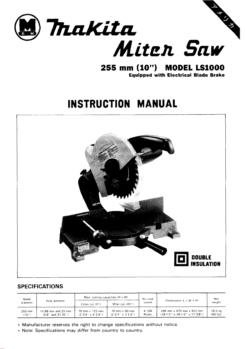
Mitea
SKW
255
mm
(10")
MODEL
Equipped with Electrical Blade Brake
INSTRUCTION MANUAL
LSlOOO
SPEC
I F I
CAT
I 0 N
S
Max
cuitinq
capacifies
Blade
d,amefe,
255
mm
1lO"l
*
Manufacturer reserves the right to change specifications without notice.
*
Note: Specifications may differ from country to country.
1
15 88
15,8"
Hole
mm
and
diamerer
and
31
25
Cross cut
I0"I
mm
I
70
mm
x
122
3/4" x 4 3)4
mm
12
32
I
IH x WI
1
Miter
cut
145"l
70
mm
x
90
mm
4.100
I
I
12
3,4"
x
3 112") I Rlmin 1 119
496
Dirneriiion~
mm
x
470
112"
x
18 1
DOUBLE
INSULA1 'ION
IL
x W x
HI
mm
x
442 mm 18
2" x 17
3r8"I
I
Ne1
weigh1
0
140lbsl
kg
Page 2
BEFORE CONNECTING YOUR TOOL
TO
A POWER SOURCE
Be sure you have read all
GENERAL POWER TOOL SAFETY RULES
GENERAL SAFETY PRECAUTIONS
(For
All
Tools)
1.
KNOW YOUR POWER TOOL. Read the owner's manual carefully. Learn the
tools applications and limitations, as well as the specific potential hazards
peculiar to
2.
KEEP GUARDS IN PLACE and in working order.
3.
REMOVE ADJUSTING KEYS AND WRENCHES. Form habit of checking to
see that keys and adjusting wrenches are removed from tool before turning
it
on.
4.
KEEP WORK AREA CLEAN. Cluttered areas and benches invite accidents.
5.
DON'T USE IN DANGEROUS ENVIRONMENT. Don't use power tools in damp
or wet locations, or expose them to rain. Keep work area well lighted.
6.
KEEP CHILDREN AWAY. All visitors should be kept safe distance from work
area.
7.
MAKE WORKSHOP KID PROOF with padlocks, master switches, or by
removing starter keys.
8.
DON'T FORCE TOOL.
it
was designed.
9.
USE RIGHT TOOL. Don't force tool or attachment to do a job for which
was not designed.
IO.
WEAR PROPER APPAREL. Wear no loose clothing, gloves, neckties, rings,
bracelets, or other jewelry which may get caught
footwear is recommended. Wear protective hair covering to contain long hair.
11.
ALWAYS USE SAFETY GLASSES. Also use face or dust mask if cutting operation is dusty. Everyday eyeglasses only have impact resistant lenses, they
are NOT safety glasses.
12.
SECURE WORK. Use clamps or a vise to hold work when practical. It's safer
than using your hand and
13.
DON'T OVERREACH. Keep proper footing and balance at all times.
14.
MAINTAIN TOOLS WITH CARE. Keep tools sharp and clean for best and
safest performance. Follow instructions for lubricating and changing accessories.
15.
DISCONNECT TOOLS before servicing; when changing accessories such as
blades, bits, cutters, and the like.
it.
It
will do the job better and safer at the rate for which
in
moving parts. Nonslip
it
frees both hands to operate tool.
it
2
Page 3
16.
REDUCE THE RISK OF UNINTENTIONAL STARTING. Make sure switch is
in off position before plugging in.
17.
USE RECOMMENDED ACCESSORIES. Consult the owner's manual for
recommended accessories. The use of improper accessories may cause risk
of injury to persons.
18.
NEVER STAND ON TOOL. Serious injury could occur if the tool is tipped or
if the cutting tool is accidentally contacted.
19.
CHECK DAMAGED PARTS. Before further use of the tool, a guard or other
it
part that is damaged should be carefully checked to determine that
operate properly and perform its intended function - check for alignment
of moving parts, binding of moving parts, breakage of parts, mounting, and
any other conditions that may affect its operation. A guard or other part that
is damaged should be properly repaired or replaced.
20.
DIRECTION
of rotation of the blade or cutter only.
21.
NEVER LEAVE TOOL RUNNING UNATTENDED. TURN POWER OFF. Don't
leave
22.
This tool is intend d for residential use only.
23.
When servicing use only identical replacement parts.
VOLTAGE WARNING: Before connecting the tool to a power source (receptacle,
outlet, etc.) be sure the voltage supplied is the same as that specified on the
nameplate of the tool. A power source
for the tool can result
the tool. If
voltage less than the nameplate rating is harmful to the motor.
tool
in
OF
FEED. Feed work into a blade or cutter against the direction
until
it
comes to a complete stop.
9
with
voltage greater than that specified
in
SERIOUS INJURY to the user - as well as damage to
doubt,
DO
NOT PLUG IN THE TOOL. Using a power source
will
with
3
Page 4
ADDITIONAL SAFETY RULES
1.
Don't use the tool in the presence of flammable liquids or gases.
2.
Check the blade carefully for cracks or damage before operation. Replace
cracked or damaged blade immediately.
3.
Use only flanges specified for this tool.
4.
Be careful not to damage the arbor, flanges (especially the installing sur-
in
face) or bolt. Damage to these parts could result
5.
Make sure that the turn base is properly secured
operation.
6.
Always keep the table top clear of chips, small pieces and
to maintain a safe, clean surface.
7.
Avoid cutting nails. Inspect for and remove all nails from the workpiece be-
fore operation.
8.
Make sure the shaft lock is released before the switch is turned on.
9.
Be sure that the blade does not contact the turn base in the lowest position.
IO.
Hold the handle firmly.
11.
Keep hands away from rotating parts.
12.
Make sure the blade is not contacting the workpiece before the switch is
turned on.
13.
Before using the tool on an actual workpiece, let
for vibration or wobbling that could indicate poor installation or a poorly
balanced blade.
14.
Wait
until
the blade attains full speed before cutting.
15.
Stop operation immediately if you notice anything abnormal.
16.
Do
not attempt to lock the trigger in the on position.
17.
Always switch off and wait for the blade to come to a complete stop before
removing, securing workpiece, changing workpiece position, angle or the
blade itself.
18.
Don't abuse cord. Never yank cord to disconnect
cord away from heat, oil, water and sharp edges.
blade breakage.
so
it
will not move during
so
on
it
run for a while. Watch
it
from the receptacle. Keep
in
order
WARNING
For Your Own Safety Read Instruction
Manual Before Operating Miter Saw
1.
Wear eye protection.
2.
Keep hands out of path of saw blade.
3.
Do
not operate saw without guards
4.
Do
not perform any operation freehand.
5.
Never reach around saw blade.
6.
Shut off power and wait for saw blade to stop before servicing or adjusting
tool.
in
place.
SAVE THESE INSTRUCTIONS.
4
Page 5
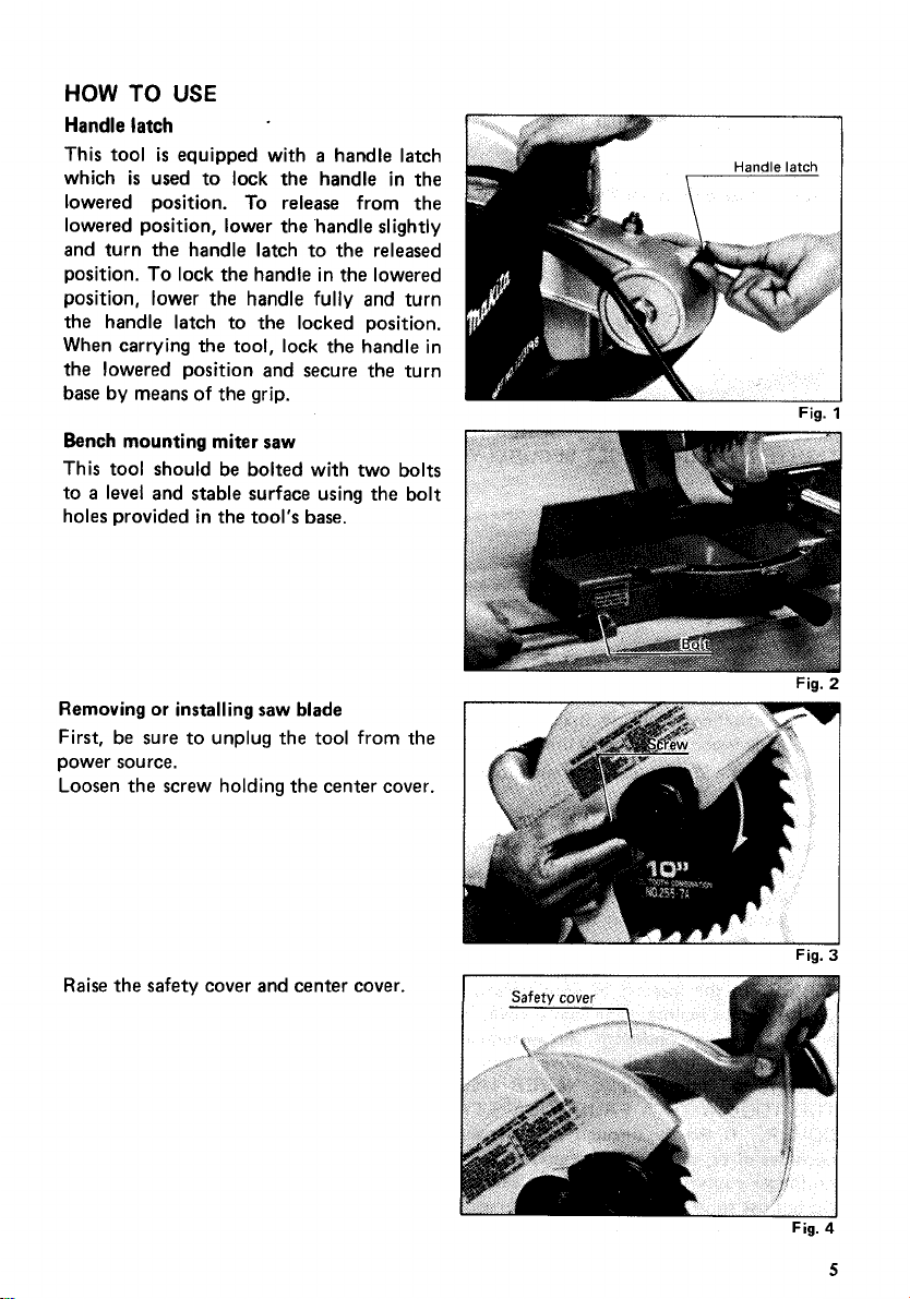
HOW
TO
USE
Handle latch
This tool
which
is
equipped with a handle latch
is
used to lock the handle in the
lowered position. To release from the
lowered position, lower the handle slightly
and turn the handle latch to the released
To
position.
lock the handle in the lowered
position, lower the handle fully and turn
the handle latch to the locked position.
When carrying the tool, lock the handle in
the lowered position and secure the turn
base by means of the grip.
Bench mounting miter saw
This tool should be bolted with two bolts
to
a
level
and stable surface using the bolt
holes provided in the tool's base.
Removing
or
installing saw blade
First, be sure to unplug the tool from the
power source.
Loosen the screw holding the center cover.
i
Handle
latch
Fig.
Fig.
1
2
Raise
the safety cover and center cover.
Fig.
Fig.
3
4
5
Page 6

Fig.
Fig.
CAUTION
:
*When installing the blade, make sure that the direction of the arrow on the surface of
is
the blade
0
Use only the Makita socket wrench to install or remove the blade.
Safety
compatible with that on the blade
cover
case.
When cutting operations are performed,
the safety cover rises
as
a
result of contact
with the workpiece. The cover returns to
its
original position when the cut
pleted and the handle
DEFEAT
COVER.
OR
REMOVE THE SAFETY
In the interest of your personal
is
raised. NEVER
is
com-
safety, always maintain the safety cover in
a
freely moving condition. Any irregular
operation of the safety cover should
be corrected immediately. NEVER USE
THE TOOL WITH A FAULTY SAFETY
COVER. If the see-through safety cover
it
becomes dirty, or sawdust adheres to
in such a way that the blade and/or workpiece
no longer easily visible; unplug the saw and clean the cover carefully with a damp cloth.
Do
not use solvents or any petroleum-based cleaners on the plastic cover.
5
6
is
6
Page 7

Maintaining maximum cutting capacity
Unplug the tool before any adjustment
is
attempted.
is
This tool
the max. cutting capacity for
(1
0")
saw blade. When the diameter of the
factory adjusted to provide
a
255"
blade has been reduced due to sharpening,
loosen the hex nut
housing. Use
depth adjusting bolt. The saw blade
at
the rear of the gear
a
screwdriver to adjust the
is
lowered by turning the depth adjusting
bolt counterclockwise and raised by turn-
it
clockwise. Adjust
ing
is
handle
in the
there will be
(4-3/4")
from the front face of the guide
so
that when the
fully
lowered position,
a
distance of about 122 mm
Fig.
fence to the point where the front edge of
the blade enters the kerf. Now tighten the
hex nut with the wrench while carefully
holding the adjusting bolt in position with
the screwdriver.
Fig.
Adjusting
for
smooth handle action
The hex lock nut holding together the gear
housing and arm has been factory adjusted
to assure smooth handle action up and
down and to guarantee precise cutting.
not tamper with
Should looseness develop
it.
at
the gear hous-
Do
ing and arm connection, perform the following adjustment. Work the handle up
and down while tightening the hex lock
nut;
the
best
position to tighten the hex
is
lock nut
weight
just before the motor body
is
obvious.
Fig.
11
After adjusting the hex lock nut, be sure the handle returns automatically to the initial
is
position from any position. If the hex lock nut
affected; if
is
a
self locking nut;
it
is
too tight,
it
is
it
will be hard to work the handle up and down. Note that this
a
special type that does not loose in normal use.
too loose, the cutting accuracy will be
It
should not
be overtightened or replaced with other types of nuts.
I
9
7
Page 8

Positioning for miter angle
Loosen the grip by turning counterclock-
wise. Press down the latch spring. This
allows the turn base to turn freely. When
you have moved the grip to the position
where the pointer indicates the desired
angle on the miter
scale,
release the latch
spring and securely tighten the grip clockwise.
Latch
spring
P
Fig.
NOTE
:
The latch spring automatically locates miter angles
of
0,
15,22.5,30
and
45
degrees. To
11
select one of these angles, turn the turn base near the desired angle while releasing the
latch spring and allow the latch spring to
seat
itself in the miter notch. Then tighten the
grip securely.
Alignment for squareness
This tool was carefully adjusted and aligned for squareness of cut
rough handling may have affected the alignment. If your tool
at
the factory, but
is
not aligned properly,
perform the following.
I
Loosen the grip and
set
the turn base
at
zero degree by turning the turn base and
allowing the latch spring to
seat
itself in
the miter notch.
is
If the pointer on the indication plate
at
zero on the miter scale, gently tighten
not
the grip and then loosen the screws on the
indication plate. Adjust the indication
plate
so
that the pointer will
the miter scale. Then tighten the screws
on the indication plate. Tighten the grip
be
at
zero
on
1
Fig.
12
securely and loosen the hex bolts on the
guide fence.Square the side of the blade with the side of the guide fence using a ruler
(try-square or the like). Then securely tighten the hex bolts on the guide fence.
8
Page 9

Emptying
When the dust bag
dust
bag
is
about half full, remove the dust bag from the tool and pull
the fastener out. Empty the dust bag of
contents, tapping
it
lightly
so
as
to
its
remove
particles adhering to the insides which
might hamper collection.
I
Securing workpiece
By
turning the knob on the
can be moved rapidly in and out.
secured.
its
To
grip workpieces, turn the knob gently clockwise, until the projection reaches
topmost position, then fasten securely.
vise
counterclockwise, the screw
By
turning the knob clockwise, the screw remains
If
being turned clockwise, the projection may stop
is
back counterclockwise until the screw
CAUTION
:
released, before turning again gently clock~se.
.Grip workpieces only when the projec-
tion
is
at
the topmost position. Other-
wise the workpiece cannot be properly
gripped and might pop out or damage the
blade.
the knob
at
an angle. In this
Fig.
is
released and the
is
forced in or pulled out while
case,
vise
turn the knob
14
shaft
(Dangerous way
0
When making miter cuts of
35
degrees or more, to the side that the
safety cover movement may be slightly obstructed by the
the workpiece dimensions are more than
(2-3/8“) in height, or
in height.
If
this situation occurs, re-mount the
less
than
90
90
mm (3-1/2”) in width and
mm (3-1/2”) in width and
vise
on the other side of the tool’s base.
to
grip workpiece)
vise
is
vise.
This only occurs when
less
less
than 30 mm (1-3/16”)
Fig.
17
mounted, the
than 60 mm
9
Page 10

Switch action
To prevent the trigger from being acciden-
tally pulled,
as
a
safety feature.
To start the tool, press
button and pull the trigger.
trigger to stop.
CAUTION
0
Before plugging in the tool, always check to
and returns to the
When not using the tool, remove the lock-off button. This prevents unauthorized opera-
tion.
Operation
When cutting with this tool, the thickness
of the blade
cutting line should be on either the left or
right side of the groove in the kerf board.
Switch on the tool and wait until the blade
attains full speed before lowering gently
into the cut. When the blade contacts the
workpiece, gradually bear down on the
handle to perform the cut. When the cut
completed, switch off the tool and WAIT
UNTIL THE BLADE HAS COME
COMPLETE STOP before returning the
blade to
cut piece could otherwise contact the
coasting blade and be thrown around dangerously.
a
lock-off button
:
"OFF"
is
cut
as
well. Therefore, your
its
fully elevated position. A thin-
is
provided
in
the lock-off
Release
position when released.
TO
the
is
A
see
that the trigger switch actuates properly
Fig.
18
2
x
4
When cutting
Cuts
of
45
degrees can be done
long
as
the workpiece
tically. To cut vertically positioned work-
piece, insert
measuring
tween the workpiece and the guide fence.
10
1/2"
(1-518"
a
space block or scrap of wood
(12") in thickness be-
x
3-112")
as
usual
is
not positioned ver-
as
I
I
,-.---->
/I
!I
j
Guide
fence
Workpiece
Page 11

Carrying
When carrying the tool, lower the handle
fully and turn the handle latch to the
locked position. Also secure the turn base
by means
conveniently carried by the carrying handle.
tool
of
the grip. The tool can then be
MAINTENANCE
CAUTION
Always be sure that the tool
inspection or maintenance.
Replacing carbon brushes
Remove and check the carbon brushes
regularly. Replace when they wear down
to about
carbon brushes clean and free to slip in the
holders. Both carbon brushes should
replaced
carbon brushes.
Use
holder caps. Take out the worn carbon
brushes, insert the new ones and secure the
brush holder caps.
:
is
switched off and unplugged before attempting to perform
6
mm
(1/4")
at
the same time. Use only Makita
a
screwdriver to remove the brush
or less. Keep the
be
I
6mm
(1/4")
Fig.
Fig.
21
2:
To maintain product SAFETY and RELIABILITY, repairs, any other maintenance or
adjustment should be performed by Makita Authorized or Factory Service Centers,
always using Makita replacement parts.
11
Page 12

ACCESSORIES
CAUTION:
These accessories or attachments are recommended for use with your Makita tool specified in this
manual. The use of any other accessories or attachments might present a risk
The accessories or attachments should be used only in the proper and intended manner.
e
0
Dust
bag
Part No.
122319-8
Lock-off button
Part No.
0
Saw blades
Chisel tooth combination
41 1478-6
2
PCS.
saw
blade
~
Part No.
792317-2
Socket wrench
Part No.
0
Ring
Part No.
For
For rip and cross-cut work.
Most frequently used for general carpentry.
255-7A 255 (10') 15.88 (5/8") 36
NO.
a
(16)
25
782212-4
257022-3
mm
13
(31/32")
Dia. Hole dia. No.
(mm) (mm) teeth
of
injury to persons.
arbor
hole
Miter
saw
Carbide-tipped
12
blade
saw
blade
For
smooth cutting of wood.
Part
No.
7920774 I 255-4
NO.
I
255(10') I 25(31/32") 1 100
792078-4 I 255-4A I 255
Fast, smoother, longer sawing without blade
sharpening. Cuts wood, dry wall, plastics.
No.
Part
. .
.
For aluminum cutting.
Dia. Hole dia.
(mm) (mm)
(10") I 25 (31/32")
Dia.
teeth
1
No.
100
Page 13

@ma
255
mm
MITER
Model
(IO")
SAW
LSIOOO
Oci
-04-'85
EN
13
Page 14

Note: The switch, noise suppressor and other part configurations
may differ from country
to
country.
14
Page 15

MACHINE
~
1 1 Spindle Lock Ishaft Lock)
2
1
Baffle Plate
1
0
Ring
3
4
1
5
1
6
1
7
1
6
1
9
2
10
1
11
1
12 1
13 1
14 4
16 4
17 3 Pan Head
18
2
19 2
20
2
21
1
22 2 Pan Head
23 1
24 1
25
1
26
1
21
1
26 1
29
1 Cord Guard
30
1
31
1
32
1
33
1
34 1
35 1 Pan Head
39
2
40
1
41 1
42
1
43
1
44
1
45 1 t Pan
46 1 Rubbersleeve
47
1
46
1
49 1
50
1
51
1
52 1
53
1
54 4 Pan Head
55
1
56
1
57 1
Note
The switch
32
Ball
Bearing
6ZOILL6
Fan
92
ARMATURE ASSEMBLY
(With
item
5
Bearing
Hex
Bolt
Housing
Plate
Head
Brush
Holder Cap
Head
cover
Relief
Head
Bare
MlOx7O
Washer
Nu1 M10
Square
26
Head
Washer
Hex
Nut
Cane
Hex
Flange
Outer
Flange
Inner Flange
Bearing
Retainer
Spindle
Thin
Washer
noise
wppressor and
-
Washer
6200LB
M5x65
Screw
Screw
Screw
Screw
Screw
10
Screw
Screw
~5~12
Neck
Screw
6
M5
Head
55
55
Screw
I7
lnsulatton
Ball
+
Rubbei Pin 4
FIELD ASSEMBLY
Motor
Name
Rivelo-5
Pan
Carbon
Brush
Pan
Clamp
Strain
Noise Suppressor
Handlecover
Pan
Switch
Clamp
Cord
Screw
Flat
Hex
Cushion
Pan Head
Key 4
wlngnoit
Cap
Plate
Spring
Safety cover
Spring
Blade
81
lWith Washer1
M5x75
M4x30
M4x16
M4x18
M4x6
M5x22
M4x14
Boll
M5
5
Boll
M5x20
71
(With Washer)
(With Washerl
(With Washer1
(With Washer)
(With Washer1
(With Washerl
(With Washerl
M5x8
Max20
(With Washerl
other
par1 SpeClfKatlOnS
MACHINE
~
58
1
59
1
60
1
1
61
62
1
63
I
64 4 Hex
65
1 Guide
66
1
67
1
68
1
69
1
70 1
71
1 Stopper
72
1
73
I
74 1 + Pan Head
75 1
76
1 Hex NufM16-24
77
1
18
1
79
1
80
1 Holder
81
1
82
1
83 1
84
1
85
1
86 2
87
1
88
1
89
1
90
1
91
1
1
92
93
1
94
1
95
2
96
1 Indication Label
97
1
98
1 Grip 32
99
1 Knock Spring
100
1
101
2
102
1
103
1
104 1
io5
2
106
1 Holder
107
2
108
2
109 1 TurnBase
110 2 SpringPin5-18
differ
from
may
Country
nail
Beallng
6203~~8
Bearing
BOX
Helical
Gear 41
Retaining
Ring
Needle
Bearing
Gear
Housing
Boll
M10x25
Rule
(Guide
Setscrew
M10
Hex
BoltM16
Flat
Washer
16
Arm
Torsion
Spring
Wave Washer
Thin
Washer
Screw
Flat Washer
16
Chip
Deflector
Kerf
Board
set
Plate
Screw
M6x12
Base
Nut
Holder
Pan Heed
Screw
set
Plate
Prolecler
~eiease
NUT
R
Release
Nut
L
vice
~~m
Knob
45
Flat
Washer
12
Vice
Plate
Flat
Washer 6
Pan Head
Screw
Pan Head
Screw
Plate
Pan
Head
Screw
Hex
Bolt
M8x25
Leaf
stay
Knock Pin
Turning
Stay
wlngnoit
~6x12
Hex Socket Head
Sprlng
Washer
10
country
S
~
17
1210
(With Washerl
Fence1
32
8
8
M5x14
M6x14
M4x8
M5x30
(With Washed
Boll
10
M6
lWith Washer1
lWilh Washer)
(With Washerl
M10x35
15
Page 16

MAKITA
LIMITED
ONE YEAR WARRANTY
Warranty Policy
Every Makita tool is thoroughly inspected and tested before leaving the factory. It is warranted to
be free of defects from workmanship and materials for the period of ONE YEAR from the date of
original purchase. Should any trouble develop during this one-year period, return the COMPLETE
tool, freight prepaid, to one of Makita’s Factory or Authorized Service Centers. If inspection shows
the trouble is caused by defective workmanship
replace) without charge.
This Warranty does not apply where:
repairs have been made
e
repairs are required because of normal wear and tear
e
The tool has been abused, misused or improperly maintained;
e
alterations have been made to the tool.
IN
NO
EVENT SHALL MAKITA BE LIABLE FOR ANY INDIRECT, INCIDENTAL OR CON-
SEQUENTIAL DAMAGES FROM THE SALE OR USE OF THE PRODUCT. THIS DISCLAIMER
APPLIES BOTH DURING AND AFTER THE TERM OF THIS WARRANTY.
MAKITA DISCLAIMS LIABILITY FOR ANY IMPLIED WARRANTIES, INCLUDING IMPLIED
WARRANTIES OF “MERCHANTABILITY“ AND “FITNESS FOR A SPECIFIC PURPOSE,”
AFTER THE ONE-YEAR TERM OF THIS WARRANTY.
This Warranty gives you specific legal rights, and you may also have other rights which vary from
state to state. Some states do not allow the exclusion or Limitation
so
damages,
limitation on how long an implied warranty lasts,
the above limitation or exclusion may not apply to you. Some states do not allow
or
attempted by others:
or
material, Makita will repair (or at our option,
of
incidental or consequential
so
the above limitation may not apply to you.
~~
11-8,3-chome, Sumiyoshi-eho, Anjo, Aichi
wln&x,Ltd.
446,
Japan
PRINTED IN JAPAN
1986
-
3
-
N
 Loading...