

Page 1
GB Slide Compound Miter Saw Instruction manual
F Scie à Onglet Radiale Manuel d’instructions
D Kapp- und Gehrungssäge Betriebsanleitung
I Troncatrice radiale per legno Istruzioni per l’uso
NL Schuifbare samengesteld- Gebruiksaanwijzing
verstekzaag
E Sierra de Inglete Telescópica Manual de instrucciones
P Serra de Esquadria c/ Braço Manual de instruções
Telescópico
DK Afkorter- og geringssav Brugsanvisning
GR Συρόμενο σύνθετο φαλτσοπρίονο Οδηγίες χρήσης
TR
Kızaklı Birleşik Gönyeburun Testere
Kullanım kılavuzu
LS0815F
LS0815FL
1078301
Page 2
1 000030 2 010228
1
2
2
3
7
7
3 011382 4 014305
6
4
5
5 1078316 6 010386
8
6
7 010387 8 014287
2
Page 3
9
10
8
11 12
3
15
14
16
17
18
19
20
21
22
20
23
25
24
13
9 001800 10 1078317
11 001540 12 010233
23
13 1078403 14 014281
20
26
25
15 1078303 16 1078304
3
Page 4
17 011352 18 010388
17
28
29
30
31
33
34
32
19 014271 20 014275
21 014270 22 014274
4
Page 5
23 014282 24 014303
35
36
1
37
38
39
40
7
38
41
41
9
43
44
9
45
46
47
38
41
40
37
25 010390 26 010391
27 010392 28 014309
42
5
Page 6
29 010560 30 1078305
37
38
39
7
40
48
49
50
51
13
52
53
52
31 014283 32 001549
33 014595 34 014647
6
Page 7
35 1078306
54 55
56
6
16
27
36 1078307
27
37 1078308
7
Page 8
57 58 59
(1) (2) (3) (4)
60 61
Fig. A
16
62
63
64
63
65
66 66
38 1078309 39 001555
60
(1)
(2)
(1)
(2)
(1)
(4)
(3)
(1)
(2)
(2)
61
(1)
(2)
40 001556 41 001557
42 010404
43 014279
8
Page 9
44 001563 45 014292
67
16
69
6
20
19
23
24
69
9
72
16
22
68
46 014273 47 1078315
48 1078310 49 1078311
50 1078312 51 001819
70
71
9
Page 10
52 1078313 53 1078314
6
20
25
73 71
77
75
54 007834 55 010256
10
Page 11

ENGLISH (Original instructions)
Explanation of general view
1. Stopper pin
2. Bolts
3. Adjusting bolt
4. Holder
5. Holder assembly
6. Screw
7. Blade guard
8. Kerf board
9. Saw blade
10. Blade teeth
11. Left bevel cut
12. Straight cut
13. Turn base
14. Top surface of turn base
15. Periphery of blade
16. Guide fence
17. Stopper arm
18. Adjusting screw
19. Miter scale
20. Pointer
21. Lock lever
22. Grip
23. Lever
24. Arm
25. Bevel scale
26. Release button
27. Locking screw
28. Lock-off button
29. Switch trigger
30. Hole for padlock
31. Switch for laser
32. Screw holding the laser unit box
33. Light
34. Switch for light
35. Socket wrench with hex wrench
on its other end
36. Wrench holder
37. Socket wrench
38. Blade case
39. Center cover
40. Hex bolt
41. Arrow
42. Shaft lock
43. Hex bolt (left-handed)
44. Outer flange
45. Ring
46. Inner flange
47. Spindle
48. Dust nozzle
49. Dust bag
50. Fastener
51. Support
52. Sliding fence
53. Clamping screw
54. Vise arm
55. Vise knob
56. Vise rod
57. 52/38° type crown molding
58. 45° type crown molding
59. 45° type cove molding
60. Inside corner
61. Outside corner
62. Vise
63. Spacer block
64. Aluminum extrusion
65. Over 450 mm
66. Holes
67. Cut grooves with blade
68. Hex bolts
69. Triangular rule
70. 0° adjusting bolt
71. Left 45° bevel angle adjusting bolt
72. Top surface of turn table
73. Right 5° bevel angle adjusting bolt
74. Screwdriver
75. Brush holder cap
SPECIFICATIONS
Model LS0815F LS0815FL
Blade diameter 216 mm
Hole diameter
Max. kerf thickness of the saw blade 2.8 mm
• Due to our continuing program of research and development, the specifications herein are subject to change without
notice.
• Specifications may differ from country to country.
• Weight according to EPTA-Procedure 01/2014
Countries other than Europe
European countries 30 mm
Max. miter angle Right 60°, Left 50°
Max. bevel angle Right 5°, Left 48°
No load speed (RPM) 5,000 min
Laser type –
Dimensions (L x W x H) 755 mm x 450 mm x 488 mm
Net weight 15.5 kg
Safety class /II
25.4 mm or 30 mm
(country specific)
-1
1 mW < (Laser Class 2M)
Red Laser 650 nm,
Maximum output
11
Page 12
Max. Cutting capacities (H x W) with 216 mm in diameter
Miter angle
0° 50 mm x 305 mm 60 mm x 305 mm 65 mm x 305 mm
45° 50 mm x 215 mm - 65 mm x 215 mm
60° (right) - - 65 mm x 150 mm
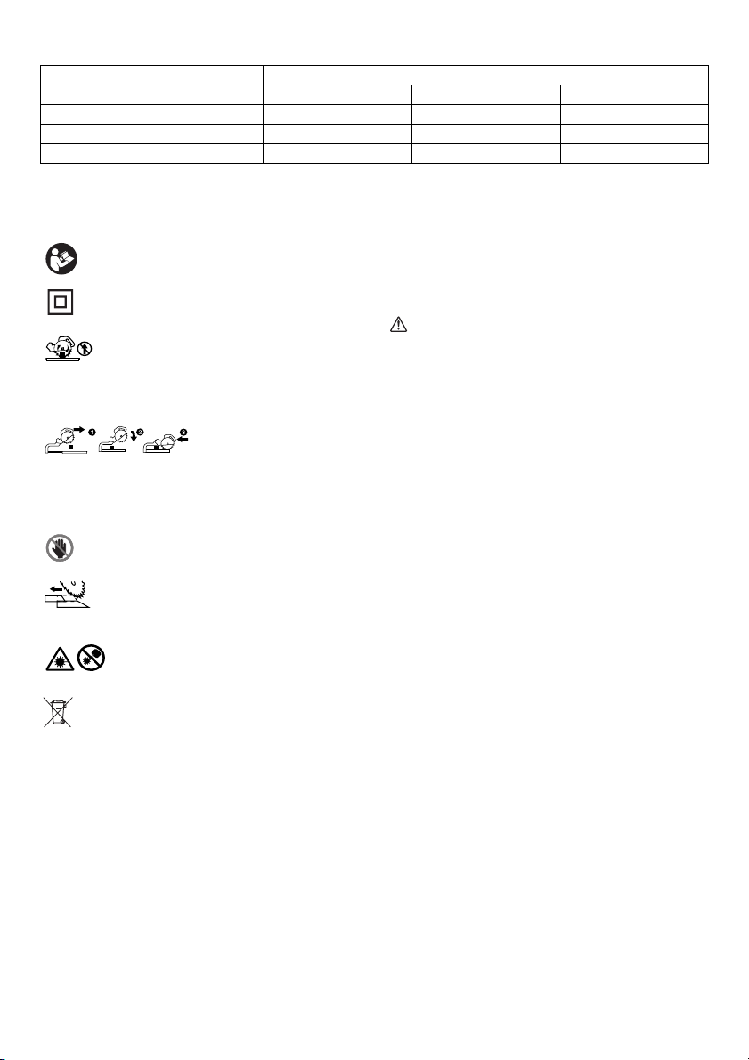
Symbols
The following show the symbols used for the equipment.
Be sure that you understand their meaning before use.
............. Read instruction manual.
............. DOUBLE INSULATION
......... To avoid injury from flying debris, keep
holding the saw head down, after making
cuts, until the blade has come to a
complete stop.
When performing slide cut, first pull
carriage fully and press down handle,
then push carriage toward the guide
fence.
............. Do not place hand or fingers close to the
blade.
.......... Adjust sliding fences clear of blade and
blade guard properly.
...... LASER RADIATION: Do not stare into
beam. Direct laser beam may injure your
eyes.
............... Only for EU countries
Do not dispose of electric equipment
together with household waste material!
In observance of the European Directive,
on Waste Electric and Electronic
Equipment and its implementation in
accordance with national law, electric
equipment that have reached the end of
their life must be collected separately and
returned to an environmentally
compatible recycling facility.
Intended use
The tool is intended for accurate straight and miter cutting
in wood. With appropriate saw blades, aluminum can also
be sawed.
Power supply
The tool should be connected only to a power supply of
the same voltage as indicated on the nameplate, and can
only be operated on single-phase AC supply. They are
double-insulated and can, therefore, also be used from
sockets without earth wire.
45° (left) 5° (right) 0°
END326-1
ENE006-1
ENF002-2
Bevel angle
SAFETY WARNINGS
General power tool safety
warnings
WARNING: Read all safety warnings, instructions,
illustrations and specifications provided with this
power tool. Failure to follow all instructions listed below
may result in electric shock, fire and/or serious injury.
GEA010-2
Save all warnings and
instructions for future reference.
The term “power tool” in the warnings refers to your
mains-operated (corded) power tool or battery-operated
(cordless) power tool.
Safety instructions for mitre saws
ENB130-2
1. Mitre saws are intended to cut wood or wood-like
products, they cannot be used with abrasive cut-
off wheels for cutting ferrous material such as
bars, rods, studs, etc. Abrasive dust causes moving
parts such as the lower guard to jam. Sparks from
abrasive cutting will burn the lower guard, the kerf
insert and other plastic parts.
2. Use clamps to support the workpiece whenever
possible. If supporting the workpiece by hand, you
must always keep your hand at least 100 mm from
either side of the saw blade. Do not use this saw to
cut pieces that are too small to be securely
clamped or held by hand. If your hand is placed too
close to the saw blade, there is an increased risk of
injury from blade contact.
3. The workpiece must be stationary and clamped or
held against both the fence and the table. Do not
feed the workpiece into the blade or cut
“freehand” in any way. Unrestrained or moving
workpieces could be thrown at high speeds, causing
injury.
4. Push the saw through the workpiece. Do not pull
the saw through the workpiece. To make a cut,
raise the saw head and pull it out over the
workpiece without cutting, start the motor, press
the saw head down and push the saw through the
workpiece. Cutting on the pull stroke is likely to cause
the saw blade to climb on top of the workpiece and
violently throw the blade assembly towards the
operator.
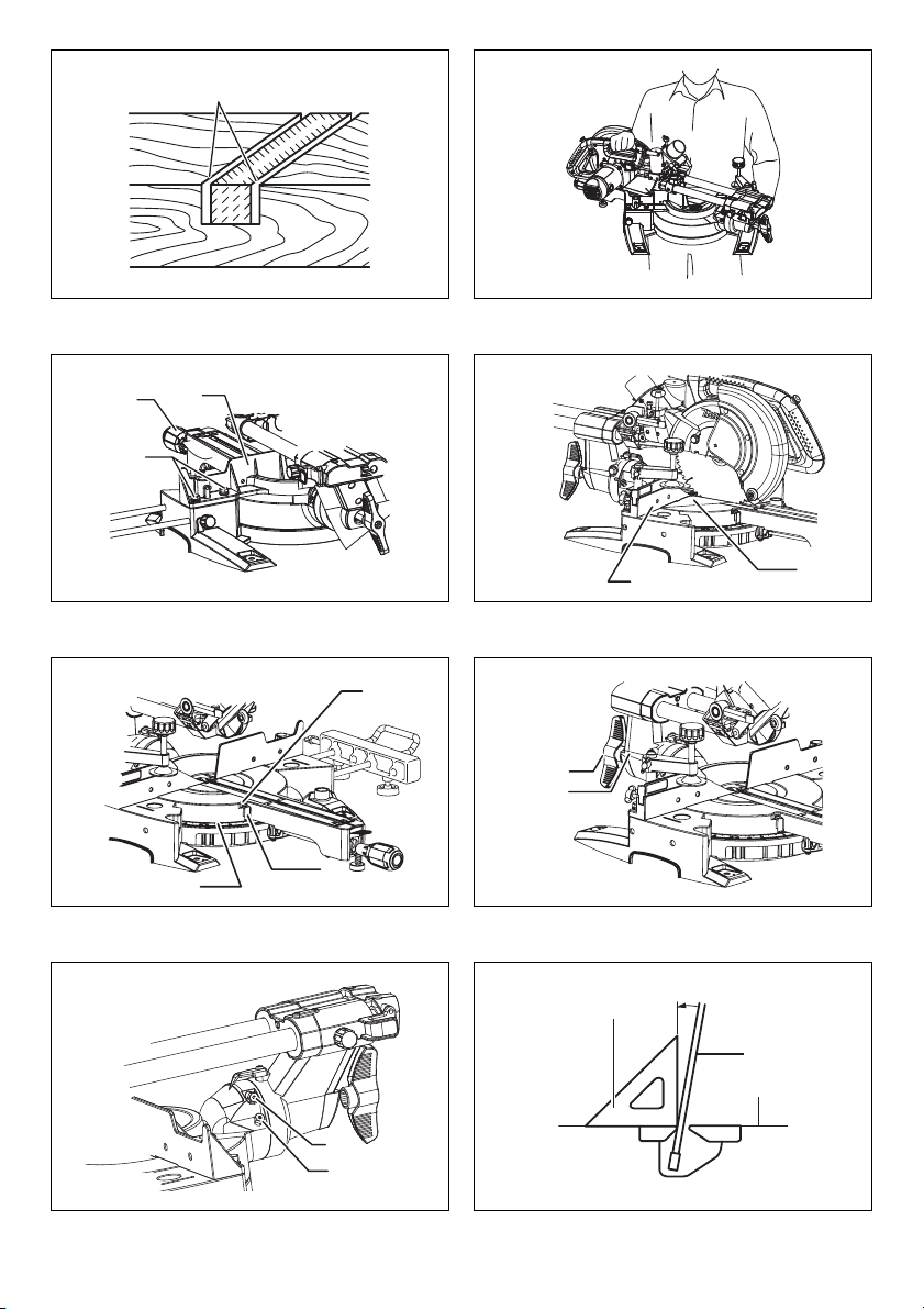
5. Never cross your hand over the intended line of
cutting either in front or behind the saw blade.
12
Page 13

Supporting the workpiece “cross handed” i.e. holding
the workpiece to the right of the saw blade with your
left hand or vice versa is very dangerous. (Fig. 1)
6. Do not reach behind the fence with either hand
closer than 100 mm from either side of the saw
blade, to remove wood scraps, or for any other
reason while the blade is spinning. The proximity of
the spinning saw blade to your hand may not be
obvious and you may be seriously injured.
7. Inspect your workpiece before cutting. If the
workpiece is bowed or warped, clamp it with the
outside bowed face toward the fence. Always
make certain that there is no gap between the
workpiece, fence and table along the line of the
cut. Bent or warped workpieces can twist or shift and
may cause binding on the spinning saw blade while
cutting. There should be no nails or foreign objects in
the workpiece.
8. Do not use the saw until the table is clear of all
tools, wood scraps, etc., except for the workpiece.
Small debris or loose pieces of wood or other objects
that contact the revolving blade can be thrown with
high speed.
9. Cut only one workpiece at a time. Stacked multiple
workpieces cannot be adequately clamped or braced
and may bind on the blade or shift during cutting.
10. Ensure the mitre saw is mounted or placed on a
level, firm work surface before use. A level and firm
work surface reduces the risk of the mitre saw
becoming unstable.
11. Plan your work. Every time you change the bevel
or mitre angle setting, make sure the adjustable
fence is set correctly to support the workpiece
and will not interfere with the blade or the
guarding system. Without turning the tool “ON” and
with no workpiece on the table, move the saw blade
through a complete simulated cut to assure there will
be no interference or danger of cutting the fence.
12. Provide adequate support such as table
extensions, saw horses, etc. for a workpiece that
is wider or longer than the table top. Workpieces
longer or wider than the mitre saw table can tip if not
securely supported. If the cut-off piece or workpiece
tips, it can lift the lower guard or be thrown by the
spinning blade.
13. Do not use another person as a substitute for a
table extension or as additional support. Unstable
support for the workpiece can cause the blade to bind
or the workpiece to shift during the cutting operation
pulling you and the helper into the spinning blade.
14. The cut-off piece must not be jammed or pressed
by any means against the spinning saw blade. If
confined, i.e. using length stops, the cut-off piece
could get wedged against the blade and thrown
violently.
15. Always use a clamp or a fixture designed to
properly support round material such as rods or
tubing. Rods have a tendency to roll while being cut,
causing the blade to “bite” and pull the work with your
hand into the blade.
16. Let the blade reach full speed before contacting
the workpiece. This will reduce the risk of the
workpiece being thrown.
17. If the workpiece or blade becomes jammed, turn
the mitre saw off. Wait for all moving parts to stop
and disconnect the plug from the power source
and/or remove the battery pack. Then work to free
the jammed material. Continued sawing with a
jammed workpiece could cause loss of control or
damage to the mitre saw.
18. After finishing the cut, release the switch, hold the
saw head down and wait for the blade to stop
before removing the cut-off piece. Reaching with
your hand near the coasting blade is dangerous.
19. Hold the handle firmly when making an incomplete
cut or when releasing the switch before the saw
head is completely in the down position. The
braking action of the saw may cause the saw head to
be suddenly pulled downward, causing a risk of injury.
20. Only use the saw blade with the diameter that is
marked on the tool or specified in the manual. Use
of an incorrectly sized blade may affect the proper
g
uarding of
result in serious personal injury.
21. Only use the saw blades that are marked with a
speed equal or higher than the speed marked on
the tool.
22. Do not use the saw to cut other than wood,
aluminum or similar materials.
23. (For European countries only)
Always use the blade which conforms to EN847-1.
Additional instructions
1. Make workshop kid proof with padlocks.
2. Never stand on the tool. Serious injury could occur if
the tool is tipped or if the cutting tool is unintentionally
contacted.
3. Never leave the tool running unattended. Turn the
power off. Do not leave tool until it comes to a
complete stop.
4. Do not operate saw without guards in place.
Check blade guard for proper closing before each
use. Do not operate saw if blade guard does not
move freely and close instantly. Never clamp or tie
the blade guard into the open position.
5. Keep hands out of path of saw blade. Avoid
contact with any coasting blade. It can still cause
severe injury.
6. To reduce the risk of injury, return carriage to the
full rear position after each crosscut operation.
7. Always secure all moving portions before carrying
the tool.
8. Stopper pin which locks the cutter head down is
for carrying and storage purposes only and not for
any cutting operations.
9. Check the blade carefully for cracks or damage
before operation. Replace cracked or damaged
blade immediately. Gum and wood pitch hardened
on blades slows saw and increases potential for
kickback. Keep blade clean by first removing it
from tool, then cleaning it with gum and pitch
remover, hot water or kerosene. Never use
gasoline to clean blade.
10. While making a slide cut, KICKBACK can occur.
KICKBACK occurs when the blade binds in the
workpiece during a cutting operation and the saw
blade is driven rapidly towards the operator. Loss
of control and serious personal injury can result. If
the blade or guard operation which could
13
Page 14

blade begins to bind during a cutting operation,
do not continue to cut and release switch
immediately.
11. Use only flanges specified for this tool.
12. Be careful not to damage the arbor, flanges
(especially the installing surface) or bolt. Damage
to these parts could result in blade breakage.
13. Make sure that the turn base is properly secured
so it will not move during operation. Use the holes
in the base to fasten the saw to a stable work
platform or bench. NEVER use tool where operator
positioning would be awkward.
14. Make sure the shaft lock is released before the
switch is turned on.
15. Be sure that the blade does not contact the turn
base in the lowest position.
16. Hold the handle firmly. Be aware that the saw
moves up or down slightly during start-up and
stopping.
17. Make sure the blade is not contacting the
workpiece before the switch is turned on.
18. Before using the tool on an actual workpiece, let it
run for a while. Watch for vibration or wobbling
that could indicate poor installation or a poorly
balanced blade.
19. Stop operation immediately if you notice anything
abnormal.
20. Do not attempt to lock the trigger in the “ON”
position.
21. Always use accessories recommended in this
manual. Use of improper accessories such as
abrasive wheels may cause an injury.
22. Some material contains chemicals which may be
toxic. Take caution to prevent dust inhalation and
skin contact. Follow material supplier safety data.
Additional safety rules for the laser
1. LASER RADIATION, DO NOT STARE INTO THE
BEAM OR VIEW DIRECTLY WITH OPTICAL
INSTRUMENTS, CLASS 2M LASER PRODUCT.
SAVE THESE INSTRUCTIONS.
WARNING:
DO NOT let comfort or familiarity with product (gained
from repeated use) replace strict adherence to safety
rules for the subject product. MISUSE or failure to
follow the safety rules stated in this instruction
manual may cause serious personal injury.
INSTALLATION
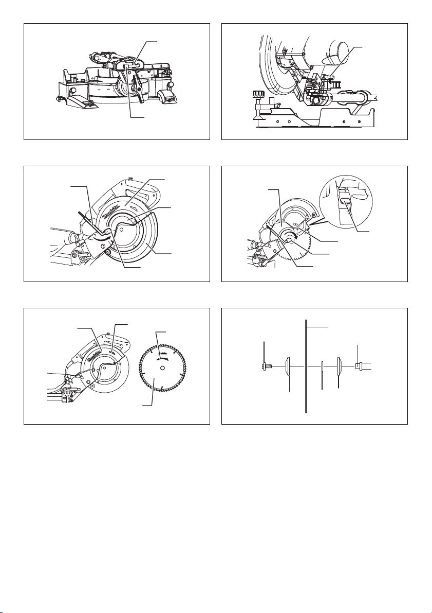
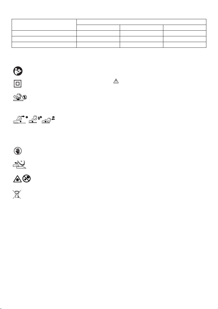
Bench mounting (Fig. 2)
When the tool is shipped, the handle is locked in the
lowered position by the stopper pin. Release the stopper
pin by simultaneously applying a slight downward
pressure on the handle and pulling the stopper pin.
WARNING:
• Ensure that the tool will not move on the
supporting surface. Movement of the miter saw on
the supporting surface while cutting may result in loss
of control and serious personal injury. (Fig. 3)
This tool should be bolted with four bolts to a level and
stable surface using the bolt holes provided in the tool’s
14
base. This will help prevent tipping and possible injury.
(Fig. 4)
Turn the adjusting bolt clockwise or counterclockwise so
that it comes into a contact with the tool surface to keep
the tool stable.
Installing the holders and holder
assemblies
NOTE:
• In some countries, the holders and holder assemblies
may not be included in the tool package as standard
accessory. (Fig. 5)
The holders and the holder assemblies support
workpieces horizontally.
Install the holders and the holder assemblies on both side
as shown in the figure.
Then tighten the screws firmly to secure the holders and
the holder assemblies.
FUNCTIONAL DESCRIPTION
WARNING:
• Always be sure that the tool is switched off and
unplugged before adjusting or checking function
on the tool. Failure to switch off and unplug the tool
may result in serious personal injury from accidental
start-up.
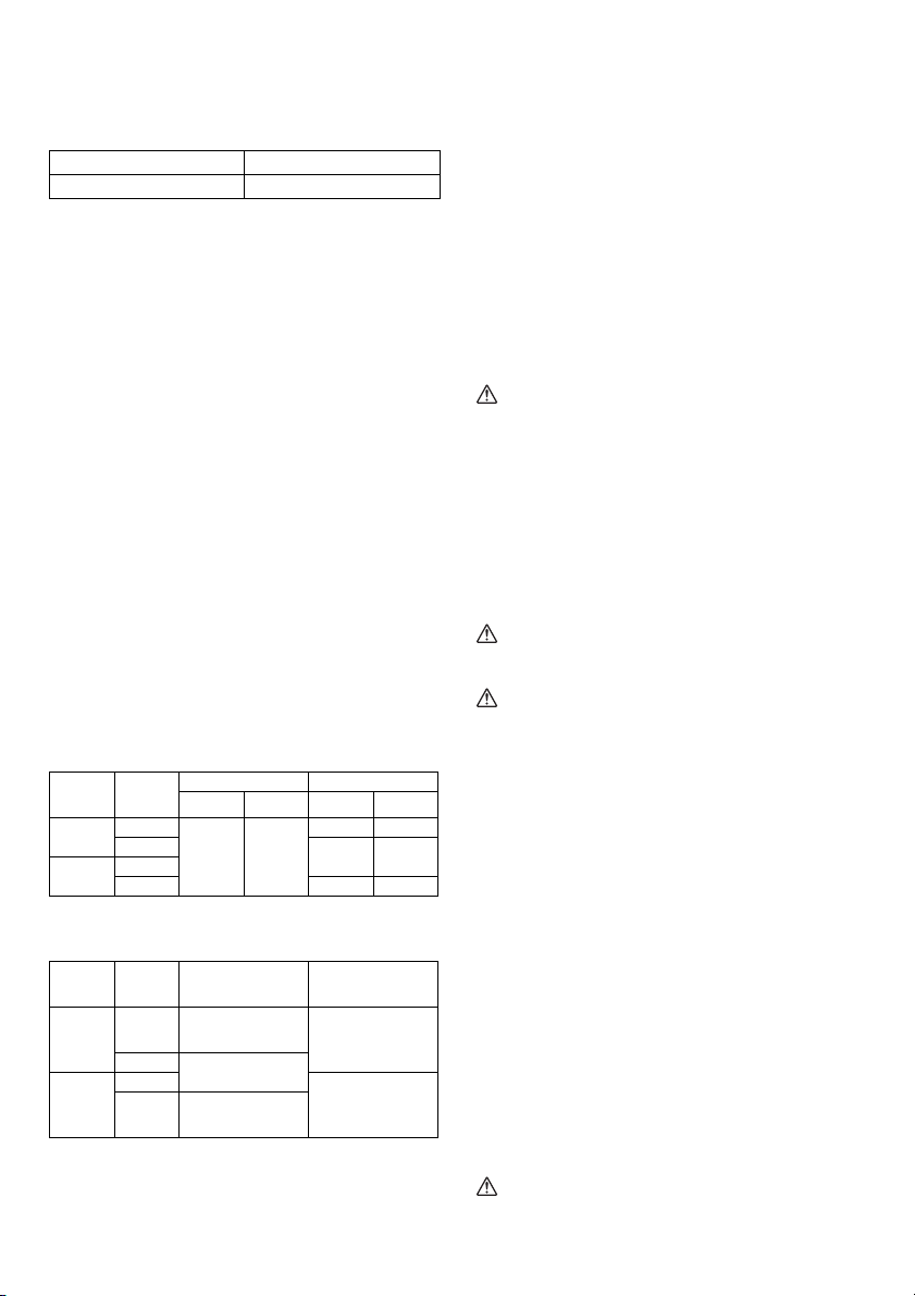
Blade guard (Fig. 6)
When lowering the handle, the blade guard rises
automatically. The blade guard returns to its original
position when the cut is completed and the handle is
raised.
WARNING:
• Never defeat or remove the blade guard or the
spring which attaches to the guard. An exposed
blade as a result of defeated guarding may result in
serious personal injury during operation.
In the interest of your personal safety, always maintain the
blade guard in good condition. Any irregular operation of
the blade guard should be corrected immediately. Check
to assure spring loaded return action of guard.
WARNING:
• Never use the tool if the blade guard or spring are
damaged, faulty or removed. Operation of the tool
with a damaged, faulty or removed guard may result in
serious personal injury.
If the see-through blade guard becomes dirty, or sawdust
adheres to it in such a way that the blade and/or
workpiece is no longer easily visible, unplug the saw and
clean the guard carefully with a damp cloth. Do not use
solvents or any petroleum-based cleaners on the plastic
guard because this may cause damage to the guard.
If the blade guard becomes dirty and needs to be cleaned
for proper operation follow the steps below:
With the tool switched off and unplugged, use the
supplied socket wrench to loosen the hex bolt holding the
center cover. Loosen the hex bolt by turning it
counterclockwise and raise the blade guard and center
cover. (Fig. 7)
With the blade guard so positioned, cleaning can be more
completely and efficiently accomplished. When cleaning is
Page 15

complete reverse procedure above and secure bolt. Do
not remove spring holding blade guard. If guard becomes
damaged through age or UV light exposure, contact a
Makita service center for a new guard. DO NOT DEFEAT
OR REMOVE GUARD.
Positioning kerf board (Fig. 8 & 9)
This tool is provided with the kerf boards in the turn base
to minimize tearing on the exit side of a cut. The kerf
boards are factory adjusted so that the saw blade does
not contact the kerf boards. Before use, adjust the kerf
boards as follows:
First, unplug the tool. Loosen all the screws (3 each on left
and right) securing the kerf boards. Re-tighten them only
to the extent that the kerf boards can still be easily moved
by hand. Lower the handle fully and push in the stopper
pin to lock the handle in the lowered position. Loosen the
screw which secures the slide poles. Pull the carriage
toward you fully. Adjust the kerf boards so that the kerf
boards just contact the sides of the blade teeth. Tighten
the front screws (do not tighten firmly). Push the carriage
toward the guide fence fully and adjust the kerf boards so
that the kerf boards just contact the sides of blade teeth.
Tighten the rear screws (do not tighten firmly).
After adjusting the kerf boards, release the stopper pin
and raise the handle. Then tighten all the screws securely.
NOTICE:
• After setting the bevel angle ensure that the kerf
boards are adjusted properly. Correct adjustment of
the kerf boards will help provide proper support of the
workpiece minimizing workpiece tear out.
Maintaining maximum cutting capacity
This tool is factory adjusted to provide the maximum
cutting capacity for a 216 mm saw blade.
Unplug the tool before any adjustment is attempted.
When installing a new blade, always check the lower limit
position of the blade and if necessary, adjust it as follows:
(Fig. 10 & 11)
First, unplug the tool. Push the carriage toward the guide
fence fully and lower the handle completely. Use the hex.
wrench to turn the adjusting bolt until the periphery of the
blade extends slightly below the top surface of the turn
base at the point where the front face of the guide fence
meets the top surface of the turn base.
With the tool unplugged, rotate the blade by hand while
holding the handle all the way down to be sure that the
blade does not contact any part of the lower base. Readjust slightly, if necessary.
WARNING:
• After installing a new blade and with the tool
unplugged, always be sure that the blade does not
contact any part of the lower base when the handle
is lowered completely. If a blade makes contact with
the base it may cause kickback and result in serious
personal injury.
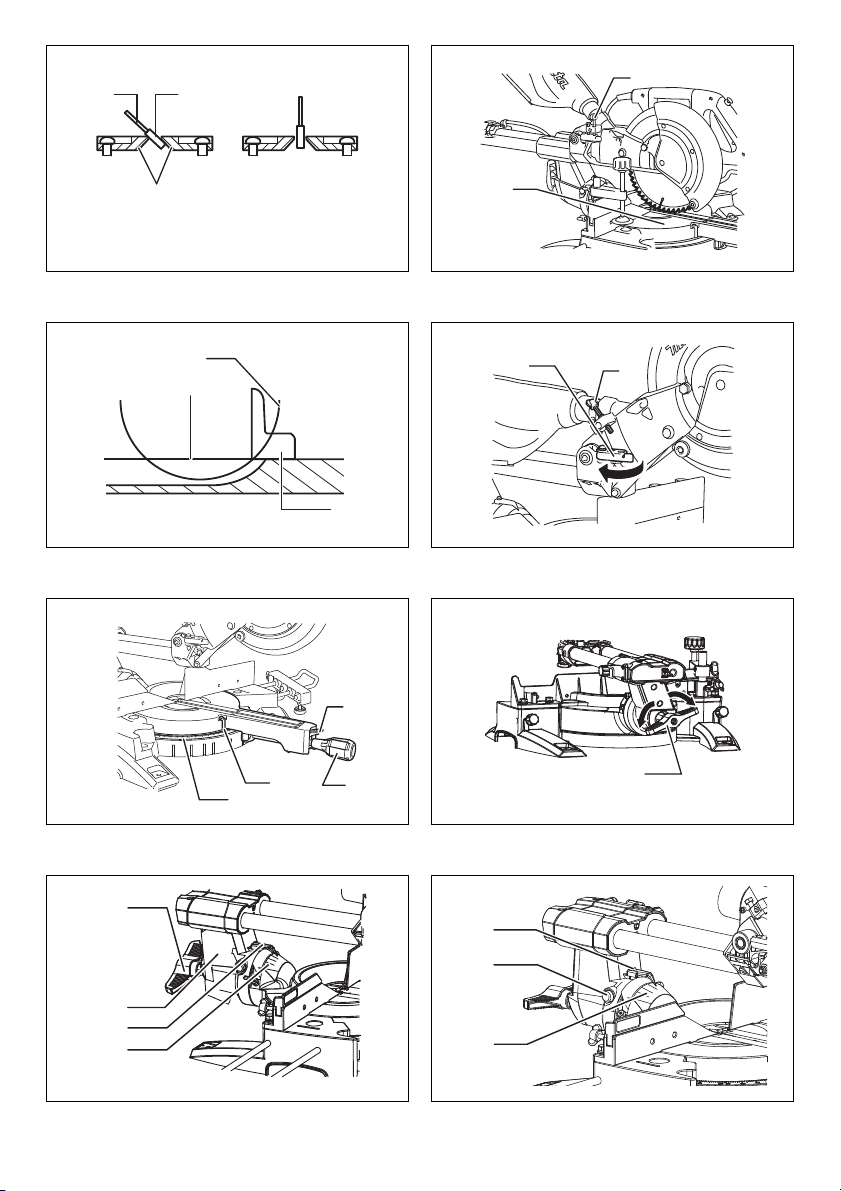
Stopper arm (Fig. 12)
The lower limit position of the blade can be easily
adjusted with the stopper arm. To adjust it, move the
stopper arm in the direction of the arrow as shown in the
figure. Adjust the adjusting screw so that the blade stops
at the desired position when lowering the handle fully.
Adjusting the miter angle (Fig. 13)
Loosen the grip by turning counterclockwise. Turn the turn
base while pressing down the lock lever. When you have
moved the grip to the position where the pointer points to
the desired angle on the miter scale, securely tighten the
grip clockwise.
CAUTION:
• After changing the miter angle, always secure the turn
base by tightening the grip firmly.
NOTICE:
• When turning the turn base, be sure to raise the handle
fully.
Adjusting the bevel angle (Fig. 14)
To adjust the bevel angle, loosen the lever at the rear of
the tool counterclockwise. Unlock the arm by pushing the
handle somewhat strongly in the direction that you intend
to tilt the saw blade.
NOTE:
• Lever can be adjusted to a different lever angle by
removing the screw holding the lever and securing the
lever at a desired angle. (Fig. 15)
Tilt the saw blade until the pointer points to the desired
angle on the bevel scale. Then tighten the lever clockwise
firmly to secure the arm. (Fig. 16)
To tilt the saw blade to right 5° or left 48°: set the saw
blade to 0° for right 5°, or 45° for left 48°. Then slightly tilt
the saw blade to the opposite side. Push the release
button and tilt the saw blade to the desired position.
Tighten the lever to secure the arm.
CAUTION:
• After changing the bevel angle, always secure the arm
by tightening the lever clockwise.
NOTICE:
• When tilting the saw blade be sure the handle is fully
raised.
• When changing bevel angles, be sure to position the
kerf boards appropriately as explained in the
“Positioning kerf board” section.
Slide lock adjustment (Fig. 17)
To lock the slide pole, turn the locking screw clockwise.
Switch action (Fig. 18)
To prevent the switch trigger from being accidentally
pulled, a lock-off button is provided. To start the tool,
press in the lock-off button and pull the switch trigger.
Release the switch trigger to stop.
WARNING:
• Before plugging in the tool, always check to see
that the switch trigger actuates properly and
returns to the “OFF” position when released. Do
not pull the switch trigger hard without pressing in
the lock-off button. This can cause switch
breakage. Operating a tool with a switch that does not
actuate properly can lead to loss of control and serious
personal injury.
A hole is provided in the switch trigger for insertion of
padlock to lock the tool off.
15
Page 16

WARNING:
• Do not use a lock with a shank or cable any smaller
than 6.35 mm in diameter. A smaller shank or cable
may not properly lock the tool in the off position and
unintentional operation may occur resulting in serious
personal injury.
• NEVER use tool without a fully operative switch
trigger. Any tool with an inoperative switch is HIGHLY
DANGEROUS and must be repaired before further
usage or serious personal injury may occur.
• For your safety, this tool is equipped with a lock-off
button which prevents the tool from unintended
starting. NEVER use the tool if it runs when you simply
pull the switch trigger without pressing the lock-off
button. A switch in need of repair may result in
unintentional operation and serious personal injury.
Return tool to a Makita service center for proper repairs
BEFORE further usage.
• NEVER defeat the lock-off button by taping down or
some other means. A switch with a defeated lock-off
button may result in unintentional operation and
serious personal injury.
Electronic function
Soft start feature
This function allows the smooth start-up of the tool by
limiting the start-up torque.
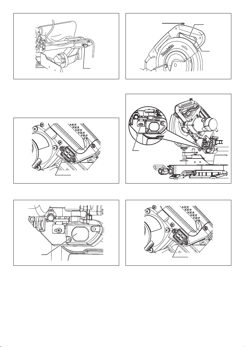
Laser beam action
For model LS0815FL only
CAUTION:
• When not in use, be sure to turn off the laser. (Fig. 19)
CAUTION:
• Never look into the laser beam. Direct laser beam may
injure your eyes.
• LASER RADIATION, DO NOT STARE INTO THE
BEAM OR VIEW DIRECTLY WITH OPTICAL
INSTRUMENTS, CLASS 2M LASER PRODUCT.
• Before shifting the laser line or performing
maintenance adjustment, be sure to unplug the tool.
To turn on the laser beam, press the upper position (ON)
of the switch. To turn off the laser beam, press the lower
position (OFF) of the switch.
Laser line can be shifted to either the left or right side of
the saw blade by loosening the screw holding the laser
unit box and shifting it in the desired direction. After
shifting, be sure to tighten the screw. (Fig. 20)
Laser line is factory adjusted so that it is positioned within
1 mm from the side surface of the blade (cutting position).
NOTE:
• When laser line appears dim and hard to see because
of direct sunlight, relocate the work area to a place
where there is less direct sunlight.
Cleaning of the lens for the laser light
If the lens for the laser light becomes dirty, or sawdust
adheres to it in such a way that the laser line is no longer
easily visible, unplug the saw and remove and clean the
lens for the laser light carefully with a damp, soft cloth. Do
not use solvents or any petroleum-based cleaners on the
lens.
16
NOTE:
• When laser line is dim and almost or entirely invisible
because of the direct sunlight in the indoor or outdoor
window-by work, relocate the work area to a place not
exposed to the direct sunlight.
Light action (Fig. 21 & 22)
To turn on the light, press the upper position (ON) of the
switch. To turn off the light, press the lower position (OFF)
of the switch.
CAUTION:
• Do not look in the light or see the source of light
directly.
NOTE:
• Use a dry cloth to wipe the dirt off the lens of lamp.
• Be careful not to scratch the lens of lamp, or it may to
lower the luminance.
ASSEMBLY
WARNING:
• Always be sure that the tool is switched off and
unplugged before working on the tool. Failure to
switch off and unplug the tool may result in serious
personal injury.
Storage of socket wrench with hex
wrench on its other end (Fig. 23)
The socket wrench is stored as shown in the figure. When
the socket wrench is needed it can be pulled out of the
wrench holder.
After using the socket wrench it can be stored by returning
it to the wrench holder.
Installing or removing saw blade
WARNING:
• Always be sure that the tool is switched off and
unplugged before installing or removing the blade.
Accidental start up of the tool may result in serious
personal injury.
• Use only the Makita socket wrench provided to
install or remove the blade. Failure to use the wrench
may result in overtightening or insufficient tightening of
the hex bolt and serious personal injury. (Fig. 24)
Lock the handle in the raised position by pushing in the
stopper pin. (Fig. 25)
To remove the blade, use the socket wrench to loosen the
hex bolt holding the center cover by turning it
counterclockwise. Raise the blade guard and center
cover.
WARNING:
• Do not remove any screw other than the hex bolt
illustrated. If you mistakenly remove another screw
and the blade guard comes off, make sure to reassemble the blade guard. (Fig. 26)
Press the shaft lock to lock the spindle and use the socket
wrench to loosen the hex bolt clockwise. Then remove the
hex bolt, outer flange and blade.
NOTE:
• If the inner flange is removed be sure to install it on the
spindle with its protrusion facing away from the blade. If
Page 17

the flange is installed incorrectly the flange will rub
against the machine.
WARNING:
• Before mounting the blade onto the spindle, always
be sure that the correct ring for the blade’s arbor
hole you intend to use is installed between the
inner and the outer flanges. Use of the incorrect
arbor hole ring may result in the improper mounting of
the blade causing blade movement and severe
vibration resulting in possible loss of control during
operation and in serious personal injury. (Fig. 27)
To install the blade, mount it carefully onto the spindle,
making sure that the direction of the arrow on the surface
of the blade matches the direction of the arrow on the
blade case.
Install the outer flange and hex bolt, and then use the
socket wrench to tighten the hex bolt (left-handed)
securely counterclockwise while pressing the shaft lock.
(Fig. 28 & 29)
Return the blade guard and center cover to its original
position. Then tighten the hex bolt clockwise to secure the
center cover. Release the handle from the raised position
by pulling the stopper pin. Lower the handle to make sure
that the blade guard moves properly. Make sure the shaft
lock has released spindle before making cut.
Connecting a vacuum cleaner
When you wish to perform clean cutting operation,
connect a Makita vacuum cleaner.(Fig. 30)
Dust bag (Fig. 31)
The use of the dust bag makes cutting operations cleaner
and dust collection easier. To attach the dust bag, fit it
onto the dust nozzle.
When the dust bag is about half full, remove the dust bag
from the tool and pull the fastener out. Empty the dust bag
of its contents, tapping it lightly so as to remove particles
adhering to the insides which might hamper further
collection.
Securing workpiece
WARNING:
• It is extremely important to always secure the
workpiece correctly with the proper type of vise or
crown molding stoppers. Failure to do so may result
in serious personal injury and cause damage to the tool
and/or the workpiece.
• After a cutting operation do not raise the blade
until it has come to a complete stop. The raising of a
coasting blade may result in serious personal injury
and damage to the workpiece.
• When cutting a workpiece that is longer than the
support base of the saw, the material should be
supported the entire length beyond the support
base and at the same height to keep the material
level. Proper workpiece support will help avoid blade
pinch and possible kickback which may result in
serious personal injury. Do not rely solely on the
vertical vise and/or horizontal vise to secure the
workpiece. Thin material tends to sag. Support
workpiece over its entire length to avoid blade pinch
and possible KICKBACK. (Fig. 32)
Guide fence (SLIDING FENCES)
adjustment (Fig. 33)
WARNING:
• Before operating the tool, make sure that the sliding
fence is secured firmly.
• Before bevel-cutting, make sure that no part of the
tool, especially the blade, contacts the sliding
fence. when fully lowering and raising the handle in
any position and while moving the carriage
through its full range of travel. If the blade makes
contact the sliding fence may result in kickback or
unexpected movement of the material and serious
personal injury. (Fig. 34)
CAUTION:
• When performing bevel cuts, slide the sliding fence to
the left and secure it as shown in the figure. Otherwise,
it will contact the blade or a part of the tool, causing
possible serious injury to the operator.
This tool is equipped with the sliding fence which should
ordinarily be positioned as shown in the figure.
However, when performing left bevel cuts, set it to the left
position as shown in the figure if the tool head contacts it.
When bevel-cutting operations are complete, don’t forget
to return the sliding fence to the original position and
secure it by firmly tightening the clamping screw.
Vertical vise (Fig. 35)
The vertical vise can be installed on either the left or right
side of the guide fence. Insert the vise rod into the hole in
the guide fence and tighten the screw on the back of the
guide fence to secure the vise rod.
Position the vise arm according to the thickness and
shape of the workpiece and secure the vise arm by
tightening the screw. If the screw to secure the vise arm
contacts the guide fence, install the screw on the opposite
side of vise arm. Make sure that no part of the tool
contacts the vise when lowering the handle fully and
pulling or pushing the carriage all the way. If some part
contacts the vise, re-position the vise.
Press the workpiece flat against the guide fence and the
turn base. Position the workpiece at the desired cutting
position and secure it firmly by tightening the vise knob.
WARNING:
• The workpiece must be secured firmly against the
turn base and guide fence with the vise during all
operations. If the workpiece is not properly secured
against the fence the material may move during the
cutting operation causing possible damage to the
blade, causing the material to be thrown and loss of
control resulting in serious personal injury.
OPERATION
NOTICE:
• Before use, be sure to release the handle from the
lowered position by pulling the stopper pin.
• Do not apply excessive pressure on the handle when
cutting. Too much force may result in overload of the
motor and/or decreased cutting efficiency. Push down
handle with only as much force as is necessary for
smooth cutting and without significant decrease in
blade speed.
17
Page 18

• Gently press down the handle to perform the cut. If the
handle is pressed down with force or if lateral force is
applied, the blade will vibrate and leave a mark (saw
mark) in the workpiece and the precision of the cut will
be impaired.
• During a slide cut, gently push the carriage toward the
guide fence without stopping. If the carriage movement
is stopped during the cut, a mark will be left in the
workpiece and the precision of the cut will be impaired.
WARNING:
• Make sure the blade is not contacting the
workpiece, etc. before the switch is turned on.
Turning the tool on with the blade in contact with the
workpiece may result in kickback and serious personal
injury.
1. Press cutting (cutting small workpieces) (Fig. 36)
Workpieces up to 90 mm high and 60 mm wide can be
cut in the following manner.
Push the carriage toward the guide fence fully and
tighten the locking screw clockwise to secure the
carriage. Secure the workpiece correctly with the
proper type of vise. Switch on the tool without the
blade making any contact and wait until the blade
attains full speed before lowering. Then gently lower
the handle to the fully lowered position to cut the
workpiece. When the cut is completed, switch off the
tool and WAIT UNTIL THE BLADE HAS COME TO A
COMPLETE STOP before returning the blade to its
fully elevated position.
WARNING:
• Firmly tighten the knob clockwise so that the
carriage will not move during operation. Insufficient
tightening of the knob may cause possible kickback
which may result in serious personal injury.
• Never cut so small workpiece which cannot be
securely held by the vise. Improperly held workpiece
may cause kickback and serious personal injury.
2. Slide (push) cutting (cutting wide workpieces)
(Fig. 37)
Loosen the locking screw counterclockwise so that the
carriage can slide freely. Secure the workpiece with
the proper type of vise. Pull the carriage toward you
fully. Switch on the tool without the blade making any
contact and wait until the blade attains full speed.
Press the handle down and PUSH THE CARRIAGE
TOWARD THE GUIDE FENCE AND THROUGH THE
WORKPIECE. When the cut is completed, switch off
the tool and WAIT UNTIL THE BLADE HAS COME
TO A COMPLETE STOP before returning the blade to
its fully elevated position.
WARNING:
• Whenever performing a slide cut, first pull the
carriage full towards you and press the handle all
the way down, then push the carriage toward the
guide fence. Never start the cut with the carriage
not pulled fully toward you. If you perform the slide
cut without the carriage pulled fully toward you
unexpected kickback may occur and serious personal
injury may result.
• Never attempt to perform a slide cut by pulling the
carriage towards you. Pulling the carriage towards
you while cutting may cause unexpected kickback
resulting in possible serious personal injury.
• Never perform the slide cut with the handle locked in
the lowered position.
• Never loosen the locking screw which secures the
carriage while the blade is rotating. A loose carriage
while cutting may cause unexpected kickback resulting
in possible in serious personal injury.
3. Miter cutting
Refer to the previously covered “Adjusting the miter
angle”.
4. Bevel cut (Fig. 38)
Loosen the lever and tilt the saw blade to set the bevel
angle (Refer to the previously covered “Adjusting the
bevel angle”). Be sure to retighten the lever firmly to
secure the selected bevel angle safely. Secure the
workpiece with a vise. Make sure the carriage is pulled
all the way back toward the operator. Switch on the
tool without the blade making any contact and wait
until the blade attains full speed. Then gently lower the
handle to the fully lowered position while applying
pressure in parallel with the blade and PUSH THE
CARRIAGE TOWARD THE GUIDE FENCE TO CUT
THE WORKPIECE. When the cut is completed, switch
off the tool and WAIT UNTIL THE BLADE HAS COME
TO A COMPLETE STOP before returning the blade to
its fully elevated position.
WARNING:
• After setting the blade for a bevel cut, before
operating the tool ensure that the carriage and
blade will have free travel throughout the entire
range of the intended cut. Interruption of the carriage
or blade travel during the cutting operation may result
in kickback and serious personal injury.
• While making a bevel cut keep hands out of the
path of the blade. The angle of the blade may confuse
the operator as to the actual blade path while cutting
and contact with the blade will result in serious
personal injury.
• The blade should not be raised until it has come to
a complete stop. During a bevel cut the piece cut off
may come to rest against the blade. If the blade is
raised while
ejected by the blade causing the material to fragment
which may result in serious personal injury.
NOTICE:
• When pressing down the handle, apply pressure in
parallel with the blade. If a force is applied
perpendicularly to the turn base or if the pressure
direction is changed during a cut, the precision of the
cut will be impaired.
• Before bevel-cutting, an adjustment of sliding fence
maybe required. Refer to the section titled “Guide
fence adjustment”.
rotating the cut-off piece maybe
it is
18
Page 19
5. Compound cutting
Compound cutting is the process in which a bevel
angle is made at the same time in which a miter angle
is being cut on a workpiece. Compound cutting can be
performed at the angle shown in the table.
Miter angle Bevel angle
Left and Right 0° - 45° Left 0° - 45°
010340
When performing compound cutting, refer to “Press
cutting”, “Slide cutting”, “Miter cutting” and “Bevel cut”
explanations.
6. Cutting crown and cove moldings
Crown and cove moldings can be cut on a compound
miter saw with the moldings laid flat on the turn base.
There are two common types of crown moldings and
one type of cove moldings; 52/38° wall angle crown
molding, 45° wall angle crown molding and 45° wall
angle cove molding. See illustrations. (Fig. 39)
There are crown and cove molding joints which are
made to fit “Inside” 90° corners ((1) and (2) in Fig. A)
and “Outside” 90° corners ((3) and (4) in Fig. A).
(Fig. 40 & 41)
Measuring
Measure the wall length and adjust workpiece on table
to cut wall contact edge to desired length. Always
make sure that cut workpiece length at the back of
the workpiece is the same as wall length. Adjust cut
length for angle of cut. Always use several pieces for
test cuts to check the saw angles.
When cutting crown and cove moldings, set the bevel
angle and miter angle as indicated in the table (A) and
position the moldings on the top surface of the saw
base as indicated in the table (B).
In the case of left bevel cut
Table (A)
For inside
corner
For outside
corner
006361
Molding
position in
Fig. A
(1)
(2)
(3)
(4) Right 31.6° Right 35.3°
Bevel angle Miter angle
52/38° type 45° type 52/38° type 45° type
Right 31.6° Right 35.3°
Left 33.9° Left 30°
Left 31.6° Left 35.3°
Table (B)
For inside
corner
For outside
corner
006362
Molding
position in
Fig. A
Molding edge against
guide fence
Ceiling contact edge
(1)
should be against guide
fence.
(2)
Wall contact edge should
be against guide fence.
(3)
Ceiling contact edge
(4)
should be against guide
fence.
Finished piece
Finished piece will be on
the Left side of blade.
Finished piece will be on
the Right side of blade.
Example:
In the case of cutting 52/38° type crown molding for
position (1) in Fig. A:
• Tilt and secure bevel angle setting to 33.9° LEFT.
• Adjust and secure miter angle setting to 31.6°
RIGHT.
• Lay crown molding with its broad back (hidden)
surface down on the turn base with its CEILING
CONTACT EDGE against the guide fence on the
saw.
• The finished piece to be used will always be on the
LEFT side of the blade after the cut has been
made.
7. Cutting aluminum extrusion (Fig. 42)
When securing aluminum extrusions, use spacer
blocks or pieces of scrap as shown in the figure to
prevent deformation of the aluminum. Use a cutting
lubricant when cutting the aluminum extrusion to
prevent build-up of the aluminum material on the
blade.
WARNING:
• Never attempt to cut thick or round aluminum
extrusions. Thick or round aluminum extrusions can
be difficult to secure and may work loose during the
cutting operation which may result in loss of control and
serious personal injury.
8. Wood facing
Use of wood facing helps to assure splinter-free cuts
in workpieces. Attach a wood facing to the guide fence
using the holes in the guide fence.
See the figure concerning the dimensions for a
suggested wood facing. (Fig. 43)
CAUTION:
• Use straight wood of even thickness as the wood
facing.
WARNING:
• Use screws to attach the wood facing to the guide
fence. The screws should be installed so that the
screw heads are below the surface of the wood
facing so that they will not interfere with the
positioning of the material being cut. Misalignment
of the material being cut can case unexpected
movement during the cutting operation which may
result in a loss of control and serious personal injury.
NOTICE:
• When the wood facing is attached, do not turn the turn
base with the handle lowered. The blade and/or the
wood facing will be damaged.
9. Groove cutting (Fig. 44)
A dado type cut can be made by proceeding as
follows:
Adjust the lower limit position of the blade using the
adjusting screw and the stopper arm to limit the cutting
depth of the blade. Refer to “Stopper arm” section
described previously.
After adjusting the lower limit position of the blade, cut
parallel grooves across the width of the workpiece
using a slide (push) cut as shown in the figure. Then
remove the workpiece material between the grooves
with a chisel.
WARNING:
• Do not attempt to perform this type of cut by using
a wider type blade or dado blade. Attempting to
19
Page 20

make a groove cut with a wider blade or dado blade
could lead to unexpected cutting results and kickback
which may result in serious personal injury.
• Be sure to return the stopper arm to the original
position when performing other than groove
cutting. Attempting to make cuts with the stopper arm
in the incorrect position could lead to unexpected
cutting results and kickback which may result in serious
personal injury.
CAUTION:
• Be sure to return the stopper arm to the original
position when performing other than groove cutting.
Carrying tool (Fig. 45)
Make sure that the tool is unplugged. Secure the blade at
0° bevel angle and the turn base at the full right miter
angle position. Secure the slide poles so that the lower
slide pole is locked in the position of the carriage fully
pulled to operator and the upper poles are locked in the
position of the carriage fully pushed forward to the guide
fence (refer to the section titled “Slide lock adjustment”.)
Lower the handle fully and lock it in the lowered position
by pushing in the stopper pin.
Wind the power supply cord using the cord rests.
WARNING:
• Stopper pin is only for carrying and storage
purposes and should never be used for any cutting
operations. The use of the stopper pin for cutting
operations may cause unexpected movement of the
saw blade resulting in kickback and serious personal
injury.
Carry the tool by holding both sides of the tool base as
shown in the figure. If you remove the holders, dust bag,
etc., you can carry the tool more easily.
CAUTION:
• Always secure all moving portions before carrying the
tool. If portions of the tool move or slide while being
carried loss of control or balance may occur resulting in
personal injury.
MAINTENANCE
WARNING:
• Always be sure that the tool is switched off and
unplugged before attempting to perform inspection
or maintenance. Failure to unplug and switch off the
tool may result in accidental start up of the tool which
may result in serious personal injury.
• Always be sure that the blade is sharp and clean
for the best and safest performance. Attempting a
cut with a dull and /or dirty blade may cause kickback
and result in a serious personal injury.
NOTICE:
• Never use gasoline, benzine, thinner, alcohol or the
like. Discoloration, deformation or cracks may result.
Adjusting the cutting angle
This tool is carefully adjusted and aligned at the factory,
but rough handling may have affected the alignment. If
your tool is not aligned properly, perform the following:
20
1. Miter angle (Fig. 46)
Push the carriage toward the guide fence and tighten
the locking screw to secure the carriage.
Loosen the grip which secures the turn base. Turn the
turn base so that the pointer points to 0° on the miter
scale. Then turn the turn base slightly clockwise and
counterclockwise to seat the turn base in the 0° miter
notch. (Leave as it is if the pointer does not point to
0°.) Loosen the hex sockets bolts securing the guide
fence using the socket wrench. (Fig. 47)
Lower the handle fully and lock it in the lowered
position by pushing in the stopper pin. Square the side
of the blade with the face of the guide fence using a
triangular rule, try-square, etc. Then securely tighten
the hex socket bolts on the guide fence in order
starting from the right side. (Fig. 48)
Make sure that the pointer points to 0° on the miter
scale. If the pointer does not point to 0°, loosen the
screw which secures the pointer and adjust the pointer
so that it will point to 0°.
2. Bevel angle
(1) 0° bevel angle (Fig. 49)
Push the carriage toward the guide fence and
tighten the locking screw to secure the carriage.
Lower the handle fully and lock it in the lowered
position by pushing in the stopper pin. Loosen the
lever at the rear of the tool. (Fig. 50)
Turn the hex bolt on the right side of the arm two
or three revolutions counterclockwise to tilt the
blade to the right. (Fig. 51)
Carefully square the side of the blade with the top
surface of the turn base using the triangular rule,
try-square, etc. by turning the hex bolt on the right
side of the arm clockwise. Then tighten the lever
securely. (Fig. 52)
Make sure that the pointer on the arm point to 0°
on the bevel scale on the arm holder. If they do not
point to 0°, loosen the screw which secure the
pointer and adjust it so that it will point to 0°.
(2) 45° bevel angle (Fig. 53)
Adjust the 45° bevel angle only after performing 0°
bevel angle adjustment. To adjust left 45° bevel
angle, loosen the lever and tilt the blade to the left
fully. Make sure that the pointer on the arm points
to 45° on the bevel scale on the arm holder. If the
pointer does not point to 45°, turn the 45° bevel
angle adjusting bolt on the right side of the arm
holder until the pointer points to 45°.
To adjust the right 5° bevel angle, perform the
same procedure as that described above.
Replacing carbon brushes (Fig. 54)
Remove and check the carbon brushes regularly. Replace
when they wear down to 3 mm in length. Keep the carbon
brushes clean and free to slip in the holders. Both carbon
brushes should be replaced at the same time. Use only
identical carbon brushes. (Fig. 55)
Use a screwdriver to remove the brush holder caps. Take
out the worn carbon brushes, insert the new ones and
secure the brush holder caps.
After use
• After use, wipe off chips and dust adhering to the tool
with a cloth or the like. Keep the blade guard clean
Page 21

according to the directions in the previously covered
section titled “Blade guard”. Lubricate the sliding
portions with machine oil to prevent rust.
• When storing the tool, pull the carriage toward you fully.
To maintain product SAFETY and RELIABILITY, repairs,
any other maintenance or adjustment should be
performed by Makita Authorized Service Centers, always
using Makita replacement parts.
OPTIONAL ACCESSORIES
WARNING:
• These Makita accessories or attachments are
recommended for use with your Makita tool
specified in this manual. The use of any other
accessories or attachments may result in serious
personal injury.
• Only use the Makita accessory or attachment for its
stated purpose. Misuse of an accessory or
attachment may result in serious personal injury.
If you need any assistance for more details regarding
these accessories, ask your local Makita Service Center.
• Steel & Carbide-tipped saw blades
(Refer to our website or contact your local Makita
dealer for the correct saw blades to be used for the
material to be cut.)
• Vertical vise
• Socket wrench with hex wrench on its other end
• Holder
• Holder assembly
• Dust bag
• Triangular rule
NOTE:
• Some items in the list may be included in the tool
package as standard accessories. They may differ
from country to country.
Noise
The typical A-weighted noise level determined according
to EN62841-3-9:
Sound pressure level (L
Sound power level (L
Uncertainty (K): 3 dB (A)
): 89 dB (A)
pA
): 100 dB (A)
WA
• The declared noise emission value(s) has been
measured in accordance with a standard test method
and may be used for comparing one tool with another.
• The declared noise emission value(s) may also be
used in a preliminary assessment of exposure.
WARNING:
• Wear ear protection.
• The noise emission during actual use of the power
tool can differ from the declared value(s)
depending on the ways in which the tool is used
especially what kind of workpiece is processed.
• Be sure to identify safety measures to protect the
operator that are based on an estimation of
exposure in the actual conditions of use (taking
account of all parts of the operating cycle such as
the times when the tool is switched off and when it
is running idle in addition to the trigger time).
ENG905-1
ENG907-1
EC Declaration of Conformity
For European countries only
The EC declaration of conformity is included as Annex A
to this instruction manual.
21
Page 22

FRANÇAIS (Instructions d’origine)
1. Broche de blocage
2. Boulons
3. Boulon de réglage
4. Support
5. Assemblage de support
6. Vis
7. Protecteur de lame
8. Plateau de découpe
9. Lame
10. Dents de la lame
11. Coupe en biseau sur la gauche
12. Coupe rectiligne
13. Socle rotatif
14. Face supérieure du socle rotatif
15. Périphérie de la lame
16. Garde de guidage
17. Bras de blocage
18. Vis de réglage
19. Échelle de coupe d’onglet
20. Pointeur
21. Levier de verrouillage
22. Manche
23. Levier
24. Bras
25. Échelle de coupe en biseau
26. Bouton de déblocage
27. Vis de verrouillage
28. Bouton de sécurité
29. Gâchette
30. Trou pour cadenas
31. Interrupteur du laser
32. Vis de maintien de l’unité laser
33. Lumière
34. Interrupteur de lumière
35. Clé à douille avec clé hexagonale
36. Support à clé
37. Clé à douille
38. Boîtier de la lame
39. Couvercle central
40. Boulon hexagonal
41. Flèche
42. Blocage de l’arbre
43. Boulon hexagonal (fileté vers la
44. Flasque extérieur
45. Bague
46. Flasque intérieur
47. Axe
48. Raccord à poussières
49. Sac à poussière
50. Fermeture-éclair
51. Support
52. Ergot coulissant
SPÉCIFICATIONS
de l’autre côté
gauche)
Descriptif
53. Vis de serrage
54. Bras de l’étau
55. Bouton de serrage de l’étau
56. Tige de l’étau
57. Moulure couronnée du type 52/
38°
58. Moulure couronnée du type 45°
59. Moulure concave du type 45°
60. Coin intérieur
61. Coin extérieur
62. Étau
63. Cale d’espacement
64. Profilé d’aluminium
65. Plus de 450 mm
66. Orifices
67. Rainures de coupe avec la lame
68. Boulons hexagonaux
69. Règle triangulaire
70. Boulon de réglage 0°
71. Boulon de réglage de l’angle de
coupe en biseau 45° de gauche
72. Face supérieure de la table
rotative
73. Boulon de réglage de l’angle de
coupe en biseau 5° de droite
74. Tournevis
75. Bouchon de porte-charbon
Modèle LS0815F LS0815FL
Diamètre de la lame 216 mm
Diamètre du trou
Épaisseur max. du trait de la lame de scie 2,8 mm
Angle de coupe d’onglet max. À droite 60°, à gauche 50°
Angle de biseau max. À droite 5°, à gauche 48°
Vitesse à vide (tr/min) 5 000 min
Dimensions (L x P x H) 755 mm x 450 mm x 488 mm
Niveau de sécurité /II
• Étant donné l’évolution constante de notre programme de recherche et de développement, les spécifications
contenues dans ce manuel sont sujettes à des modifications sans préavis.
• Les spécifications peuvent varier suivant les pays.
• Poids conforme à la procédure EPTA 01/2014
22
Pays non européens
Pays d’Europe 30 mm
Type de laser –
Poids net 15,5 kg
25,4 mm ou 30 mm
(varie selon les pays)
-1
Laser rouge 650 nm,
Puissance maximale
1 mW < (classe de laser 2M)
Page 23
Capacités max. de coupe (H x P) avec une lame d’un diamètre de 216 mm
Angle de coupe d’onglet
0° 50 mm x 305 mm 60 mm x 305 mm 65 mm x 305 mm
45° 50 mm x 215 mm - 65 mm x 215 mm
60° (droite) - - 65 mm x 150 mm
Symboles
Les symboles utilisés pour l’appareil sont indiqués cidessous. Assurez-vous d’avoir bien compris leur
signification avant d’utiliser l’appareil.
............. Reportez-vous au manuel d’instructions.
............. DOUBLE ISOLATION
......... Pour éviter les blessures causées par les
projections, maintenez la tête porte-scie
orientée vers le bas après la coupe,
jusqu’à ce que la lame soit complètement
arrêtée.
Lorsque vous effectuez des coupes en
glissière, tirez complètement le chariot et
appuyez sur la poignée, puis poussez le
chariot vers le garde de guidage.
.............. N’approchez pas la main ou les doigts de
la lame.
.......... Réglez bien les ergots coulissants hors
de la trajectoire de la lame et du
protecteur de lame.
...... RAYONNEMENT LASER : ne pas fixer le
faisceau. Le faisceau laser direct peut
blesser vos yeux.
............... Pour les pays européens uniquement
Ne pas jeter les appareils électriques
dans les ordures ménagères !
Conformément à la directive européenne
relative aux déchets d’équipements
électriques et électroniques (DEEE), et à
sa transposition dans la législation
nationale, les appareils électriques
doivent être collectés à part et être
soumis à un recyclage respectueux de
l’environnement.
Utilisations
L’outil est conçu pour les coupes rectilignes et coupes
d’onglet de précision dans le bois. Avec des lames
appropriées, il permet aussi de scier l’aluminium.
Alimentation
L’outil ne doit être raccordé qu’à une alimentation de la
même tension que celle qui figure sur la plaque
signalétique, et il ne peut fonctionner que sur un courant
45° (gauche) 5° (droite) 0°
END326-1
ENE006-1
ENF002-2
Angle de coupe en biseau
secteur monophasé. Réalisé avec une double isolation, il
peut de ce fait être alimenté sans mise à la terre.
AVERTISSEMENTS DE SÉCURITÉ
Consignes de sécurité générales
pour outils électriques
AVERTISSEMENT : Veuillez lire les consignes de
sécurité, instructions, illustrations et spécifications
qui accompagnent cet outil électrique. Le non-respect
de toutes les instructions indiquées ci-dessous peut
entraîner une électrocution, un incendie et/ou de graves
blessures.
GEA010-2
Conservez toutes les mises en
garde et instructions pour
référence ultérieure.
Le terme « outil électrique » dans les avertissements fait
référence à l’outil électrique alimenté par le secteur (avec
cordon d’alimentation) ou à l’outil électrique fonctionnant
sur batterie (sans cordon d’alimentation).
Consignes de sécurité pour scies
radiales
1. Les scies radiales sont conçues pour couper le
bois ou des produits similaires au bois ; elles ne
peuvent pas être utilisées avec des meules à
tronçonner pour couper des matériaux ferreux
comme des barres, des tiges, des goujons, etc. La
poussière abrasive provoque le blocage des pièces
mobiles comme le protecteur inférieur. Les étincelles
produites par le tronçonnage abrasif brûleront le
protecteur inférieur, le pare-éclats et les autres pièces
en plastique.
2. Utilisez des dispositifs de serrage pour soutenir la
pièce si possible. Si vous soutenez la pièce avec
la main, vous devez toujours tenir votre main à au
moins 100 mm des côtés de la lame de scie.
N’utilisez pas cette scie pour découper des
morceaux trop petits pour être solidement
bloqués ou tenus avec la main. Si votre main est
placée trop près de la lame de scie, cela présente un
risque accru de blessures en cas de contact avec la
lame.
3. La pièce doit être immobile et bloquée ou
maintenue à la fois contre le guide et la table. En
aucun cas, ne poussez la pièce dans la lame, ni ne
coupez « à main levée ». Les pièces non retenues ou
ENB130-2
23
Page 24

en mouvement pourraient être projetées à grande
vitesse et vous blesser.
4. Poussez la scie à travers la pièce. Ne tirez pas la
scie à travers la pièce. Pour faire une coupe,
soulevez la tête de scie et placez-la au-dessus de
la pièce sans couper, démarrez le moteur, appuyez
la tête de scie vers le bas et poussez la scie à
travers la pièce. Couper en tirant peut faire que la
lame de scie monte sur le haut de la pièce et projette
violemment l’ensemble de la lame en direction de
l’utilisateur.
5. Ne croisez jamais les mains sur la ligne de coupe
prévue devant ou derrière la lame de scie. Soutenir
la pièce les « mains croisées », à savoir en tenant la
pièce à droite de la lame de scie avec la main gauche
et inversement, est très dangereux. (Fig. 1)
6. Ne tendez pas les mains derrière le guide plus
près que 100 mm d’un côté ou de l’autre de la lame
de scie pour retirer les chutes de bois ou pour tout
autre motif pendant que la lame tourne. La
proximité de la lame de scie en rotation avec votre
main pourrait ne pas être évidente et vous pourriez
gravement vous blesser.
7. Inspectez votre pièce avant la coupe. Si la pièce
est arquée ou tordue, serrez-la en place avec la
face externe arquée tournée vers le guide.
Assurez-vous toujours qu’il n’y a pas d’espace
entre la pièce, le guide et la table le long de la
ligne de coupe. Les pièces courbées ou tordues
peuvent se tordre ou bouger et pincer la lame de scie
en rotation pendant la coupe. La pièce ne doit pas
avoir de clous ou corps étrangers.
8. N’utilisez pas la scie tant que la table n’est pas
dégagée de tous les outils, chutes de bois, etc., à
l’exception de la pièce. Les petits débris, les
morceaux de bois détachés ou d’autres objets entrant
en contact avec la lame en rotation peuvent être
projetés à grande vitesse.
9. Coupez uniquement une pièce à la fois. Plusieurs
pièces empilées ne peuvent pas être correctement
serrées ou attachées et risquent de pincer la lame ou
de bouger pendant la coupe.
10. Avant utilisation, assurez-vous que la scie radiale
est installée ou posée sur un plan de travail plat et
solide. Un plan de travail plat et solide réduit le risque
d’instabilité de la scie radiale.
11. Planifiez votre travail. Chaque fois que vous
changez le réglage de l’angle de coupe en biseau
ou l’angle de coupe d’onglet, assurez-vous que le
guide réglable est placé correctement pour
soutenir la pièce et qu’il ne gênera pas la lame ou
le dispositif de protection. Sans mettre l’outil sous
tension (ON) et sans pièce sur la table, déplacez la
lame de scie pour une simulation de coupe complète
afin de vous assurer qu’il n’y aura pas d’interférence
ou de risque de couper le guide.
12. Prévoyez des supports adéquats comme des
rallonges de table, un chevalet de sciage, etc.,
pour les pièces plus larges ou plus longues que la
table. Les pièces plus longues ou plus larges que la
table d’appui de la scie radiale peuvent basculer si
elles ne sont pas solidement soutenues. Si la partie
coupée de la pièce ou la pièce elle-même bascule,
elle peut soulever le protecteur inférieur ou être
projetée par la lame en rotation.
13. Ne vous servez pas d’une autre personne à la
place d’une rallonge de table ou d’un support
supplémentaire. Un soutien instable de la pièce peut
pincer la lame ou faire bouger la pièce pendant la
coupe vous entraînant vous et votre assistant vers la
lame en rotation.
14. La partie coupée de la pièce ne doit pas être
coincée ou appuyée par quelque moyen que ce
soit contre la lame de scie en rotation. Si elle est
emprisonnée, au moyen de butées longitudinales par
exemple, la partie coupée de la pièce risque de se
coincer contre la lame et d’être violemment projetée.
15. Utilisez toujours un dispositif de serrage ou de
fixation conçu pour soutenir adéquatement les
pièces rondes comme les barres ou les tuyaux.
Les barres ont tendance à rouler pendant la coupe,
faisant « mordre » la lame et entraînant la pièce et
votre main sur la lame.
16. Attendez que la lame ait atteint sa pleine vitesse
avant de la mettre en contact avec la pièce. Vous
réduirez ainsi le risque de projection de la pièce.
17. S
i la pièce ou la lame se coince, mettez la scie
radiale hors tension.
pièces en mouvement s’arrêtent et débranchez la
fiche du cordon d’alimentation de la prise secteur
et/ou retirez la batterie. Puis essayez de libérer la
pièce coincée. Si vous continuez à scier avec une
pièce coincée, vous risquez de perdre le contrôle de la
scie radiale ou de l’endommager.
18. Une fois la coupe terminée, relâchez l’interrupteur,
tenez la tête de scie vers le bas et attendez l’arrêt
de la lame avant de retirer la partie coupée de la
pièce. Approcher votre main de la lame « en roue
libre » est dangereux.
19. Tenez fermement la poignée lorsque vous faites
une coupe incomplète ou lorsque vous relâchez
l’interrupteur avant d’avoir complètement abaissé
la tête de scie. Le freinage de la scie peut tirer
brusquement la tête de scie vers le bas, ce qui
présente un risque de blessure.
20. Utilisez uniquement une lame de scie ayant le
diamètre indiqué sur l’outil ou spécifié dans le
mode d’emploi. L’utilisation d’une taille incorrecte de
lame peut affecter la protection de la lame ou le
fonctionnement du carter de protection, ce qui pourrait
provoquer de graves blessures.
21. Utilisez uniquement des lames de scie sur
lesquelles est indiquée une vitesse égale ou
supérieure à la vitesse figurant sur l’outil.
22. N’utilisez pas la scie pour couper autre chose que
du bois, de l’aluminium ou des matériaux
similaires.
23. (Pour les pays européens uniquement)
Utilisez toujours une lame conforme à la norme
EN847-1.
Instructions supplémentaires
1. Faites en sorte que l’atelier ne présente pas de
dangers pour les enfants en plaçant des cadenas.
2. Ne vous tenez jamais debout sur l’outil. Vous
risqueriez de gravement vous blesser si l’outil bascule
ou si vous touchez par inadvertance l’outil de coupe.
Attendez que toutes les
24
Page 25

3. Ne laissez jamais sans surveillance un outil en
marche. Mettez-le hors tension. Attendez que
l’outil soit complètement arrêté avant de vous
éloigner.
4. N’utilisez jamais la scie sans les protecteurs en
place. Vérifiez le bon fonctionnement du
protecteur de lame avant chaque utilisation.
N’utilisez pas la scie si le protecteur de lame ne se
déplace pas librement et ne se referme pas
instantanément. N’immobilisez jamais le
protecteur de lame en position ouverte.
5. Gardez bien les mains à l’écart de la lame de scie.
Évitez tout contact avec une lame « en roue libre
». Vous pourriez vous blesser gravement.
6. Pour réduire le risque de blessure, ramenez le
chariot à la position arrière complète après
chaque coupe transversale.
7. Immobilisez toujours toutes les pièces mobiles de
l’outil avant de le transporter.
8. La broche d’arrêt qui verrouille en position basse
la tête de coupe sert à des fins de transport et de
rangement uniquement et pas pour les opérations
de coupe.
9. Vérifiez soigneusement l’absence de fissures ou
de dommages sur les lames avant l’utilisation.
Remplacez immédiatement les lames fissurées ou
abîmées. Les dépôts de colle et les copeaux de
bois qui durcissent contre la lame ralentissent la
scie et entraînent une augmentation des risques
de choc en retour. Pour nettoyer la lame, retirez-la
d’abord de l’outil, puis nettoyez-la avec un
décapant, de l’eau chaude ou du kérosène.
N’utilisez jamais d’essence pour nettoyer la lame.
10. Les coupes en glissière peuvent entraîner un
CHOC EN RETOUR. Un CHOC EN RETOUR
survient lorsque la lame se pince dans la pièce
pendant la coupe et que la lame de scie est
entraînée rapidement vers l’utilisateur. Cela
présente un risque de perte de contrôle et de
graves blessures. Si la lame commence à
accrocher pendant la coupe, ne continuez pas à
couper et relâchez immédiatement l’interrupteur.
11. N’utilisez que les flasques spécifiés pour cet outil.
12. Prenez garde de ne pas endommager l’alésage,
les flasques (tout particulièrement leur surface
d’installation) ou le boulon. Si ces pièces sont
endommagées, la lame peut se casser.
13. Assurez-vous que le socle rotatif est bien
immobilisé, afin qu’il ne risque pas de se déplacer
pendant l’opération. Utilisez les orifices sur le
socle pour fixer la scie sur une plateforme de
travail ou un établi stable. N’utilisez JAMAIS l’outil
si vous vous trouvez dans une position
incommode.
14. Assurez-vous que le blocage de l’arbre est relâché
avant de mettre la sous tension.
15. Assurez-vous que la lame ne touche pas le socle
rotatif quand elle est abaissée au maximum.
16. Tenez la poignée fermement. N’oubliez pas que la
scie se déplace légèrement de haut en bas au
démarrage et à l’arrêt.
17. Assurez-vous que la lame ne touche pas la pièce
avant de mettre la sous tension.
18. Avant d’utiliser l’outil sur la pièce, faites-le tourner
un instant à vide. Vérifiez que la lame ne présente
ni balourd ni shimmy qui pourraient résulter d’un
montage incorrect ou d’un déséquilibre.
19. Arrêtez immédiatement si vous remarquez quoi
que ce soit d’anormal.
20. Ne tentez pas de bloquer la gâchette sur la
position de marche (ON).
21. N’utilisez que les accessoires recommandés dans
ce manuel. L’utilisation d’accessoires différents,
disques à tronçonner notamment, peut entraîner
des blessures.
22. Certains matériaux contiennent des produits
chimiques qui peuvent être toxiques. Prenez
garde de ne pas avaler la poussière et évitez tout
contact avec la peau. Suivez les données de
sécurité du fournisseur du matériau.
Consignes de sécurité supplémentaires pour le laser
1. RAYONNEMENT LASER, ÉVITEZ DE REGARDER
FIXEMENT LE FAISCEAU OU DE L’OBSERVER À
L’AIDE D’INSTRUMENTS OPTIQUES, PRODUIT
LASER DE CLASSE 2M.
CONSERVEZ CES
INSTRUCTIONS.
AVERTISSEMENT :
NE vous laissez PAS tromper (au fil d’une utilisation
répétée) par un sentiment d’aisance et de familiarité
avec le produit, en négligeant le respect rigoureux
des consignes de sécurité qui accompagnent le
produit en question. La MAUVAISE UTILISATION de
l’outil ou l’ignorance des consignes de sécurité
indiquées dans ce mode d’emploi peut entraîner de
graves blessures.
INSTALLATION
Montage du banc (Fig. 2)
À la sortie d’usine de l’outil, la poignée est verrouillée en
position abaissée par la broche de blocage. Dégagez la
broche de blocage en appliquant simultanément une
légère pression vers le bas sur la poignée et en tirant sur
la broche de blocage.
AVERTISSEMENT :
• Assurez-vous que l’outil ne se déplacera pas sur la
surface de maintien. Le mouvement de la scie à
onglet sur la surface de maintien pendant la coupe
peut entraîner une perte de contrôle et de graves
blessures corporelles. (Fig. 3)
Cet outil doit être boulonné à une surface horizontale et
stable au moyen de quatre boulons fixés dans les orifices
à boulon qui se trouvent dans le socle de l’outil. Cela
aidera à prévenir le renversement de l’outil et les risques
de blessure. (Fig. 4)
Tournez le boulon de réglage dans le sens des aiguilles
d’une montre ou dans le sens contraire des aiguilles d’une
montre pour qu’il entre en contact avec la surface de
l’outil afin que ce dernier reste stable.
25
Page 26

Installation des supports et assemblages
des supports
REMARQUE :
• Dans certains pays, les supports et assemblages de
supports peuvent ne pas être inclus dans le coffret de
l’outil en tant qu’accessoires standard.
Les supports et assemblages de supports soutiennent les
pièces à travailler horizontalement.
Installez les supports et les assemblages de supports de
chaque côté, comme illustré sur la figure.
Serrez ensuite solidement les vis pour fixer les supports
et assemblages de support en place.
(Fig. 5)
DESCRIPTION DU
FONCTIONNEMENT
AVERTISSEMENT :
• Assurez-vous toujours que l’outil est éteint et
débranché avant de le régler ou vérifier son
fonctionnement. Veillez à mettre l’outil hors tension et
le débrancher pour éviter toute blessure corporelle
grave en cas de démarrage accidentel.
Protecteur de lame (Fig. 6)
Le protecteur de lame s’élève automatiquement lorsque
vous abaissez la poignée. Le protecteur de lame revient à
sa position d’origine lorsque la coupe est terminée et la
poignée relevée.
AVERTISSEMENT :
• Ne modifiez et ne retirez jamais le protecteur de
lame ou le ressort de fixation du protecteur. Une
lame exposée en raison de la modification du
protecteur risque d’entraîner de graves blessures
corporelles pendant le fonctionnement.
Pour assurer votre propre sécurité, maintenez toujours le
protecteur de lame en bon état. Tout fonctionnement
anormal du protecteur de lame doit être immédiatement
corrigé. Assurez-vous que l’action de retour du ressort
s’effectue correctement.
AVERTISSEMENT :
• N’utilisez jamais l’outil si le protecteur de lame ou
le ressort est endommagé, défectueux ou absent.
Le fonctionnement de l’outil avec un protecteur
endommagé, défectueux ou absent peut entraîner de
graves blessures corporelles.
Si le protecteur de lame transparent est sale ou recouvert
de poussières au point de rendre la lame ou la pièce peu
visible, débranchez la scie et nettoyez soigneusement le
protecteur à l’aide d’un chiffon humide. N’utilisez pas de
solvant ou d’autres nettoyants à base d’essence sur le
protecteur en plastique, au risque de l’endommager.
Si le protecteur de lame est sale et doit être nettoyé pour
fonctionner correctement, procédez comme suit :
Après avoir mis l’outil hors tension et l’avoir débranché,
utilisez la clé à douille fournie pour desserrer le boulon
hexagonal retenant le couvercle central. Desserrez le
boulon hexagonal en le tournant dans le sens contraire
des aiguilles d’une montre, puis soulevez le protecteur de
lame et le couvercle central. (Fig. 7)
Avec le protecteur de lame dans cette position, il est
possible de nettoyer le protecteur de manière plus
complète et efficace. Une fois le nettoyage terminé,
26
effectuez la procédure en sens inverse et serrez le
boulon. Ne retirez pas le ressort qui retient le protecteur
de lame. Si le protecteur est endommagé avec le temps
ou sous l’effet de l’exposition aux rayons ultraviolets,
contactez un centre de service Makita pour vous procurer
un nouveau protecteur. NE PAS MODIFIER OU
RETIRER LE CARTER.
Positionnement du plateau de découpe
(Fig. 8 et 9)
Cet outil est équipé d’un plateau de découpe, sur le socle
rotatif, pour minimiser le fendillement du côté de sortie de
la coupe. Les plateaux de découpe sont réglés en usine
de sorte qu’ils n’entrent pas en contact avec la lame.
Avant l’utilisation, ajustez les plateaux de découpe
comme suit :
Commencez par débrancher l’outil. Desserrez toutes les
vis (3 à gauche et à droite) qui immobilisent les plateaux
de découpe. Resserrez-les de façon à pouvoir déplacer
facilement les plateaux de découpe manuellement.
Abaissez complètement la poignée et enfoncez la broche
de blocage pour verrouiller la poignée dans cette position.
Desserrez la vis qui immobilise les tiges de glissement.
Tirez complètement le chariot vers vous. Réglez les
plateaux de découpe de sorte qu’ils n’entrent en contact
qu’avec les côtés des dents de la lame. Serrez les vis
avant (ne les serrez pas fermement). Poussez
complètement le chariot vers le garde de guidage et
réglez les plateaux de découpe de sorte qu’ils n’entrent
en contact qu’avec les côtés des dents de la lame. Serrez
les vis arrière (ne les serrez pas fermement).
Après le réglage des plateaux de découpe, relâchez la
broche de blocage et soulevez la poignée. Puis serrez
toutes les vis fermement.
NOTE :
• Après avoir réglé l’angle de coupe en biseau,
assurez-vous que les plateaux de découpe sont
correctement ajustés. Un ajustement correct des
plateaux de découpe permettra un meilleur soutien de
la pièce à travailler et diminuera l’usure de celle-ci.
Maintien de la capacité de coupe
maximale
Cet outil est réglé en usine pour fournir une capacité de
coupe maximale avec une lame de 216 mm.
Débranchez l’outil avant d’y entreprendre tout réglage.
Lorsque vous installez une lame neuve, vérifiez toujours
la position limite inférieure de la lame et, au besoin,
réglez-la comme suit : (Fig. 10 et 11)
Commencez par débrancher l’outil. Poussez
complètement le chariot vers le garde de guidage et
abaissez totalement la poignée. Utilisez la clé hexagonale
pour tourner le boulon de réglage jusqu’à ce que la
périphérie de la lame dépasse légèrement sous la face
supérieure du socle rotatif au point de rencontre entre le
garde de guidage et la face supérieure du socle rotatif.
L’outil débranché, tournez la lame manuellement tout en
maintenant la poignée complètement abaissée pour vous
assurer que la lame n’entre en contact avec aucune partie
du socle inférieur. Réajustez légèrement, si nécessaire.
Page 27

AVERTISSEMENT :
• Après avoir installé une lame neuve et débranché
l’outil, assurez-vous toujours que la lame n’entre
en contact avec aucune partie du socle inférieur
lorsque la poignée est complètement abaissée. Si
la lame entre en contact avec le socle, elle risque de
provoquer un choc en retour et d’entraîner de graves
blessures corporelles.
Bras de blocage (Fig. 12)
Le bras de blocage permet un réglage facile de la position
limite inférieure de la lame. Pour l’ajuster, tournez le bras
de blocage dans le sens de la flèche, tel qu’indiqué sur la
figure. Ajustez la vis de réglage de sorte que la lame
s’arrête à la position désirée lorsque la poignée est
complètement abaissée.
Réglage de l’angle de coupe d’onglet
(Fig. 13)
Desserrez le manche en le tournant dans le sens
contraire des aiguilles d’une montre. Tournez le socle
rotatif tout en abaissant le levier de verrouillage. Après
avoir déplacé le manche sur la position où l’index pointe
sur l’angle désiré sur l’échelle de coupe d’onglet, serrez
fermement le manche en tournant dans le sens des
aiguilles d’une montre.
ATTENTION :
• Après avoir changé l’angle de coupe d’onglet,
immobilisez toujours le socle rotatif en serrant
fermement le manche.
NOTE :
• Vous devez soulever la poignée complètement avant
de tourner le socle rotatif.
Réglage de l’angle de coupe en biseau
(Fig. 14)
Pour régler l’angle de coupe en biseau, desserrez le levier
à l’arrière de l’outil en tournant dans le sens contraire des
aiguilles d’une montre. Déverrouillez le bras en poussant
légèrement la poignée dans la direction d’inclinaison de la
lame.
REMARQUE :
• Pour ajuster le levier selon un angle différent, retirez la
vis de retenue du levier et positionnez le levier selon
l’angle souhaité. (Fig. 15)
Inclinez la lame jusqu’à ce que l’index indique l’angle
désiré sur l’échelle de coupe en biseau. Serrez ensuite le
levier dans le sens des aiguilles d’une montre pour
immobiliser le bras. (Fig. 16)
Pour incliner la lame vers la droite sur 5° ou vers la
gauche sur 48° : réglez la lame sur 0° pour la droite à 5°,
ou sur 45° pour la gauche à 48°. Inclinez ensuite
légèrement la lame vers le côté opposé. Enfoncez le
bouton de déblocage et inclinez la lame dans la position
souhaitée. Serrez le levier pour immobiliser le bras.
ATTENTION :
• Après avoir changé l’angle de coupe en biseau,
immobilisez toujours le bras en serrant le levier dans le
sens des aiguilles d’une montre.
NOTE :
• Pendant l’inclinaison de la lame, assurez-vous que la
poignée est entièrement relevée.
• Lorsque vous modifiez l’angle de coupe en biseau,
assurez-vous toujours de bien placer les plateaux de
découpe, tel que décrit dans la section
« Positionnement du plateau de découpe ».
Réglage du verrou de la glissière (Fig. 17)
Pour verrouiller la tige de glissement, tournez la vis de
verrouillage dans le sens des aiguilles d’une montre.
Interrupteurs (Fig. 18)
Pour éviter tout déclenchement accidentel de la gâchette,
l’outil est muni d’un bouton de sécurité. Pour démarrer
l’outil, enfoncez le bouton de sécurité puis appuyez sur la
gâchette. Pour l’arrêter, relâchez la gâchette.
AVERTISSEMENT :
• Avant de brancher l’outil, vérifiez toujours que la
gâchette fonctionne correctement et revient en
position d’arrêt (« OFF ») lorsqu’elle est relâchée.
N’appuyez pas fortement sur la gâchette sans avoir
d’abord enfoncé le bouton de sécurité. Vous
risqueriez de casser la gâchette. L’utilisation d’un
outil dont la gâchette ne fonctionne pas correctement
risque de provoquer une perte de contrôle et de graves
blessures corporelles.
Un trou a été prévu dans la gâchette pour l’insertion d’un
cadenas permettant de déverrouiller l’outil.
AVERTISSEMENT :
• N’utilisez pas un verrou dont le diamètre de la tige
ou du câble est inférieur à 6,35 mm. L’utilisation
d’une tige ou d’un câble plus petit risque de ne pas
verrouiller correctement l’outil en position d’arrêt et de
déclencher un démarrage involontaire, provoquant des
blessures corporelles graves.
• N’utilisez JAMAIS un outil dont la gâchette ne
fonctionne pas parfaitement. Tout outil dont la
gâchette ne fonctionne pas bien est EXTRÊMEMENT
DANGEREUX et doit être réparé avant toute nouvelle
utilisation, au risque de provoquer de graves blessures
corporelles.
• Pour assurer votre sécurité, cet outil est doté d’un
bouton de sécurité qui empêche le démarrage
accidentel de l’outil. N’utilisez JAMAIS l’outil s’il se met
en marche lorsque vous appuyez simplement sur la
gâchette sans avoir appuyé sur le bouton de sécurité.
Une gâchette qui ne fonctionne pas correctement
risque d’entraîner le déclenchement involontaire de
l’outil ainsi que de graves blessures corporelles.
Renvoyez l’outil à un centre de service après-vente
Makita pour le faire réparer AVANT toute autre
utilisation.
• NE modifiez JAMAIS le bouton de sécurité en tapant
dessus ou par un autre moyen. Une gâchette dont le
bouton de sécurité a été modifié peut entraîner le
déclenchement involontaire de l’outil ainsi que de
graves blessures corporelles.
27
Page 28

Fonction électronique
Fonction de démarrage graduel
Cette fonction permet le démarrage en douceur de l’outil
en limitant le couple de démarrage.
Action du faisceau laser
Pour le modèle LS0815FL uniquement
ATTENTION :
• Lorsque vous n’utilisez pas le laser, désactivez-le.
(Fig. 19)
ATTENTION :
• Ne regardez jamais directement le faisceau laser. Vous
risqueriez de vous blesser les yeux.
• RAYONNEMENT LASER, NE PAS FIXER LE
FAISCEAU NI LE REGARDER DIRECTEMENT AVEC
DES INSTRUMENTS OPTIQUES, PRODUIT LASER
DE CLASSE 2M.
• Avant de déplacer la ligne laser ou de réaliser une
opération de maintenance, assurez-vous de
débrancher l’outil.
Pour allumer le faisceau laser, appuyez sur la position
supérieure (ON) de l’interrupteur. Pour éteindre le
faisceau laser, appuyez sur la position inférieure (OFF) de
l’interrupteur.
Pour déplacer la ligne laser vers la gauche ou vers la
droite de la lame, desserrez la vis de retenue de l’unité
laser et déplacez-la dans la direction souhaitée. Après
avoir procédé au déplacement, n’oubliez pas de serrer la
vis. (Fig. 20)
La ligne laser est réglée en usine de manière à se trouver
à moins de 1 mm de la face latérale de la lame (position
de coupe).
REMARQUE :
• Lorsque la ligne laser est pâle et presque imperceptible
en raison des rayons directs du soleil, changez de
zone de travail afin de ne plus être exposé aux rayons
directs du soleil.
Nettoyage de la lentille de lumière laser
Si la lentille de lumière laser est sale ou si la sciure de
bois qui y adhère rend la ligne laser peu visible,
débranchez la scie puis retirez et nettoyez doucement la
lentille de la lumière laser avec un chiffon doux et humide.
N’utilisez aucun solvant ou nettoyant à base de pétrole
pour nettoyer la lentille.
REMARQUE :
• Si la ligne laser est trop pâle et presque imperceptible
car vous travaillez dans un endroit exposé directement
aux rayons du soleil ou près d’une fenêtre intérieure ou
extérieure, changez de zone de travail pour ne plus
être exposé directement aux rayons du soleil.
Action de la lumière (Fig. 21 et 22)
Pour allumer la lumière, appuyez sur la position
supérieure (ON) de l’interrupteur. Pour éteindre la
lumière, appuyez sur la position inférieure (OFF) de
l’interrupteur.
ATTENTION :
• Ne regardez pas directement la lumière ou la source
lumineuse.
28
REMARQUE :
• Utilisez un chiffon sec pour essuyer les saletés qui
recouvrent la lentille de la lampe.
• Prenez garde de ne pas rayer la lentille de la lampe, au
risque d’affecter sa capacité d’éclairage.
ASSEMBLAGE
AVERTISSEMENT :
• Avant d’effectuer toute intervention sur l’outil,
assurez-vous toujours qu’il est hors tension et
débranché. Veillez à mettre l’outil hors tension et le
débrancher pour éviter toute blessure corporelle grave.
Rangement de la clé à douille avec la clé
hexagonale de l’autre côté (Fig. 23)
La clé à douille doit être rangée comme illustré sur la
figure. En cas de besoin, prenez la clé à douille qui se
trouve dans le support à clé.
Après avoir utilisé la clé à douille, remettez-la dans le
support à clé.
Installation et retrait de la lame
AVERTISSEMENT :
• Assurez-vous toujours que l’outil est hors tension
et débranché avant d’installer ou de retirer la lame.
Le démarrage accidentel de l’outil peut entraîner de
graves blessures corporelles.
• Utilisez exclusivement la clé Makita à douille
fournie pour installer ou retirer la lame. Si vous
n’utilisez pas cette clé, vous risquez d’effectuer un
serrage excessif ou insuffisant du boulon hexagonal, et
de provoquer des blessures corporelles graves.
(Fig. 24)
Verrouillez la poignée en position élevée en y poussant la
broche de blocage. (Fig. 25)
Pour retirer la lame, utilisez la clé à douille pour desserrer
le boulon hexagonal qui retient le couvercle central, en
tournant dans le sens contraire des aiguilles d’une
montre. Soulevez le protecteur de lame et le couvercle
central.
AVERTISSEMENT :
• Ne retirez aucune vis. Retirez uniquement le
boulon hexagonal illustré. Si vous retirez par erreur
une vis et si le protecteur de lame se détache, veillez à
le réinstaller. (Fig. 26)
Appuyez sur le blocage de l’arbre pour verrouiller l’axe, et
utilisez la clé à douille pour desserrer le boulon hexagonal
dans le sens des aiguilles d’une montre. Retirez ensuite le
boulon hexagonal, le flasque extérieur et la lame.
REMARQUE :
• Si vous retirez le flasque intérieur, veillez à l’installer
sur l’axe, en orientant sa partie saillante à l’écart de la
lame. Si le flasque est mal installé, il frottera contre la
machine.
AVERTISSEMENT :
• Avant de monter la lame sur l’axe, assurez-vous
toujours d’avoir installé, entre les flasques
intérieur et extérieur, la bonne bague pour l’alésage
central de la lame que vous prévoyez d’utiliser.
L’utilisation d’une mauvaise bague d’alésage peut
entraîner un montage incorrect de la lame, provoquant
Page 29

un mouvement de la lame ainsi que d’importantes
vibrations et résultant en une perte de contrôle pendant
le fonctionnement et de graves blessures corporelles.
(Fig. 27)
Pour installer la lame, montez-la prudemment sur l’axe,
en vous assurant que le sens indiqué par la flèche sur la
surface de la lame correspond à celle de la flèche du
porte-lame.
Installez le flasque extérieur et le boulon hexagonal, puis
utilisez la clé à douille pour serrer le boulon hexagonal
(fileté vers la gauche) fermement en tournant dans le
sens contraire des aiguilles d’une montre tout en
appuyant sur le blocage de l’arbre. (Fig. 28 et 29)
Remettez en position initiale le protecteur de lame et le
couvercle central. Serrez ensuite le boulon hexagonal
dans le sens des aiguilles d’une montre pour immobiliser
le couvercle central. Tirez sur la broche de blocage pour
dégager la poignée de la position élevée. Abaissez la
poignée pour vous assurer que le protecteur de lame se
déplace correctement. Avant d’effectuer la coupe,
assurez-vous que le blocage de l’arbre a libéré l’axe.
Branchement à un aspirateur
Pour effectuer un travail plus propre, raccordez un
aspirateur Makita. (Fig. 30)
Sac à poussières (Fig. 31)
L’utilisation du sac à poussières permet d’effectuer la
coupe plus proprement et facilite la collecte des
poussières. Pour fixer le sac à poussières, insérez-le
dans le raccord à poussières.
Lorsque le sac à poussières est presque à moitié plein,
retirez-le de l’outil et ouvrez la fermeture-éclair. Videz le
sac en le tapotant pour détacher les particules qui
adhèrent à l’intérieur et peuvent empêcher la collecte des
poussières.
Immobiliser la pièce à travailler
AVERTISSEMENT :
• Il est extrêmement important de toujours sécuriser
correctement la pièce à travailler avec le type
d’étau ou de butée pour moulure couronnée
approprié(e). Le non-respect de cette instruction peut
entraîner de graves blessures corporelles et
endommager l’outil et/ou la pièce à travailler.
• Après la coupe, ne soulevez pas la lame avant
qu’elle soit parfaitement arrêtée. Si vous soulevez la
lame tandis qu’elle continue à tourner, vous risquez de
provoquer de graves blessures corporelles et
d’endommager la pièce à travailler.
• Si vous découpez une pièce à travailler plus longue
que le socle de la scie, vous devez faire reposer le
matériau sur toute sa longueur au-delà du socle et
à la même hauteur pour que le matériau reste de
niveau. Le soutien approprié de la pièce à travailler
permettra d’éviter que la lame se coince et provoque
un choc en retour, susceptible d’entraîner de graves
blessures corporelles. N’immobilisez pas la pièce à
travailler uniquement à l’aide de l’étau vertical et/ou de
l’étau horizontal. Les matériaux minces ont tendance à
s’affaisser. La pièce doit être soutenue sur toute sa
longueur pour éviter que la lame ne se coince, ce qui
comporte un risque de CHOC EN RETOUR. (Fig. 32)
Réglage du garde de guidage (ERGOTS
COULISSANTS) (Fig. 33)
AVERTISSEMENT :
• Avant d’utiliser l’outil, assurez-vous que l’ergot
coulissant est bien fixé.
• Avant d’effectuer une coupe en biseau, assurezvous qu’aucune partie de l’outil, notamment la
lame, n’entre en contact avec l’ergot coulissant,
lorsque vous relevez et abaissez complètement la
poignée et lorsque vous tirez ou poussez le
chariot. Si la lame entre en contact avec l’ergot
coulissant, un choc en retour ou un mouvement
inattendu du matériau risque de se produire,
occasionnant de graves blessures corporelles.
(Fig. 34)
ATTENTION :
• Lors de la réalisation de coupes en biseau, faites
glisser l’ergot coulissant vers la gauche et immobilisezle comme illustré sur la figure. Sinon, il touchera la
lame ou une pièce de l’outil, ce qui risque de blesser
grièvement l’opérateur.
L’outil est équipé d’un ergot coulissant qui devrait être
placé comme illustré sur la figure.
Cependant, lors de la réalisation de coupes en biseau,
placez-le sur la gauche comme illustré sur la figure si la
tête de scie le touche.
Lorsque les opérations de coupe en biseau sont
terminées, n’oubliez pas de ramener l’ergot coulissant en
position d’origine et de l’immobiliser en serrant fermement
la vis de serrage.
Étau vertical (Fig. 35)
L’étau vertical peut être installé du côté gauche ou du côté
droit du garde de guidage. Insérez la tige de l’étau dans le
trou du garde de guidage et serrez la vis à l’arrière du
garde de guidage pour immobiliser la tige de l’étau.
Placez le bras de l’étau en tenant compte de l’épaisseur
et de la forme de la pièce à travailler, puis immobilisez le
bras de l’étau en serrant la vis. Si la vis utilisée pour
immobiliser le bras de l’étau entre en contact avec le
garde de guidage, installez la vis sur le côté opposé du
bras de l’étau. Assurez-vous qu’aucune pièce de l’outil ne
touche l’étau lorsque vous abaissez complètement la
poignée et tirez ou poussez le chariot. Dans le cas
contraire, modifiez la position de l’étau.
Appuyez sur la pièce à travailler pour la mettre à plat
contre le garde de guidage et le socle rotatif. Placez la
pièce à travailler sur la position de coupe désirée et
immobilisez-la fermement en serrant le bouton de serrage
de l’étau.
AVERTISSEMENT :
• La pièce doit être fixée fermement contre le socle
rotatif et le garde de guidage avec l’étau lors de
tout travail de coupe. Si la pièce à travailler n’est pas
correctement fixée contre le garde, le matériau risque
de bouger pendant la coupe et ainsi d’endommager la
lame, entraînant la projection du matériau et une perte
de contrôle occasionnant de graves blessures
corporelles.
29
Page 30

FONCTIONNEMENT
NOTE :
• Avant l’utilisation, vous devez libérer la poignée de la
position abaissée en tirant sur la broche de blocage.
• N’appliquez pas une pression excessive sur la poignée
pendant la coupe. Une force excessive peut entraîner
une surcharge du moteur et/ou réduire l’efficacité de la
coupe. N’appliquez que la force nécessaire pour
abaisser la poignée afin d’effectuer une coupe en
douceur sans diminuer significativement la vitesse de
la lame.
• Abaissez doucement la poignée pour effectuer la
coupe. Si vous forcez la poignée pour l’abaisser ou si
une force latérale est appliquée, la lame vibrera et
laissera une marque (marque de scie) sur la pièce et la
précision de la coupe sera moindre.
• Lors d’une coupe en glissière, poussez doucement le
chariot vers le garde de guidage sans arrêter. Si le
mouvement du chariot est interrompu pendant la
coupe, cela laissera une marque sur la pièce et la
précision de la coupe en sera affectée.
AVERTISSEMENT :
• Avant de mettre le contact, assurez-vous que la
lame ne touche pas la pièce à travailler ou tout
autre objet.
Si vous mettez l’outil sous tension en plaçant la lame
contre la pièce à travailler, un choc en retour risque de
se produire et de provoquer de graves blessures
corporelles.
1. Coupe sous presse (coupe de petites pièces)
(Fig. 36)
Les pièces de 90 mm de hauteur et de 60 mm de
largeur maximum peuvent être coupées de la façon
suivante.
Poussez complètement le chariot vers le garde de
guidage, puis serrez la vis de verrouillage dans le
sens des aiguilles d’une montre pour immobiliser le
chariot. Sécurisez correctement la pièce à travailler
avec le type d’étau approprié. Mettez l’outil en marche
sans que la lame n’entre en contact avec quoi que ce
soit, et attendez que la lame atteigne sa pleine vitesse
avant de l’abaisser. Abaissez ensuite doucement la
poignée jusqu’en position complètement abaissée
pour couper la pièce. Une fois la coupe terminée,
coupez le contact de l’outil et ATTENDEZ L’ARRÊT
COMPLET DE LA LAME avant de relever
complètement la lame.
AVERTISSEMENT :
• Serrez fermement le bouton en le tournant dans le
sens des aiguilles d’une montre pour que le chariot
ne bouge pas pendant l’opération. Un serrage
insuffisant du bouton peut provoquer un choc en retour
et occasionner de graves blessures corporelles.
• Ne coupez jamais de morceaux de bois si petits
qu’ils ne peuvent être maintenus solidement dans
un étau. Une pièce à travailler mal retenue peut
entraîner un choc en retour et de graves blessures
corporelles.
2. Coupe en glissière (poussée) (coupe de grandes
pièces) (Fig. 37)
Desserrez la vis de verrouillage en la tournant dans le
sens contraire des aiguilles d’une montre pour que le
30
chariot puisse glisser librement. Sécurisez la pièce à
travailler avec le type d’étau approprié. Tirez
complètement le chariot vers vous. Mettez l’outil en
marche sans que la lame n’entre en contact avec quoi
que ce soit, et attendez que la lame atteigne sa pleine
vitesse. Appuyez sur la poignée et POUSSEZ LE
CHARIOT VERS LE GARDE DE GUIDAGE ET À
TRAVERS LA PIÈCE. Une fois la coupe terminée,
coupez le contact de l’outil et ATTENDEZ L’ARRÊT
COMPLET DE LA LAME avant de relever
complètement la lame.
AVERTISSEMENT :
• Chaque fois que vous effectuez une coupe en
glissière, tirez d’abord le chariot complètement
vers vous et abaissez la poignée sur sa position la
plus basse, puis poussez le chariot vers le garde
de guidage. Ne commencez jamais la coupe alors
que le chariot n’est pas complètement tiré vers
vous. Si vous effectuez la coupe en glissière sans
avoir tiré complètement le chariot vers vous, vous
risquez de provoquer un choc en retour soudain et
d’occasionner de graves blessures corporelles.
• N’effectuez jamais une coupe en glissière en tirant
le chariot vers vous. Si vous tirez le chariot vers vous
pendant la coupe, vous risquez de provoquer un choc
en retour soudain et d’occasionner de graves
blessures corporelles.
• N’effectuez jamais une coupe en glissière lorsque la
poignée est verrouillée dans sa position la plus basse.
• Ne desserrez jamais la vis de verrouillage qui
retient le chariot pendant que la lame tourne. Si le
chariot n’est pas bien fixé pendant la coupe, un choc
en retour soudain peut se produire et occasionner de
graves blessures corporelles.
3. Coupe d’onglet
Reportez-vous à la section précédente : « Réglage de
l’angle de coupe d’onglet ».
4. Coupe en biseau (Fig. 38)
Desserrez le levier et inclinez la lame pour régler
l’angle de coupe en biseau (reportez-vous à la section
précédente : « Réglage de l’angle de coupe en
biseau »). Vous devez resserrer le levier fermement
pour bien immobiliser la lame sur l’angle de coupe en
biseau sélectionné. Immobilisez la pièce à travailler à
l’aide d’un étau. Assurez-vous que le chariot est
complètement ramené vers vous. Mettez l’outil en
marche sans que la lame n’entre en contact avec quoi
que ce soit, et attendez que la lame atteigne sa pleine
vit
esse. Abaissez
position la plus basse tout en appliquant une pression
parallèle à la lame et POUSSEZ LE CHARIOT VERS
LE GARDE DE GUIDAGE POUR COUPER LA PIÈCE
À TRAVAILLER. Une fois la coupe terminée, coupez
le contact de l’outil et ATTENDEZ L’ARRÊT
COMPLET DE LA LAME avant de relever
complètement la lame.
AVERTISSEMENT :
• Après avoir réglé la lame pour une coupe en
biseau, assurez-vous avant d’utiliser l’outil que le
chariot et la lame pourront bouger aisément
pendant toute la durée de la coupe prévue.
L’interruption du chariot ou de la lame pendant
ensuite doucement la poignée sur la
Page 31

l’opération de coupe risque de provoquer un choc en
retour et de graves blessures corporelles.
• Pendant une coupe en biseau, éloignez vos mains
du trajet de la lame. L’angle de la lame peut
désorienter l’opérateur quant au trajet réel de la lame
pendant la coupe ; le contact avec la lame entraînerait
alors de graves blessures corporelles.
• La lame ne doit pas être relevée avant d’être
parfaitement arrêtée. Lors d’une coupe en biseau, il
peut arriver que la partie qui se détache de la pièce
coupée repose contre le côté de la lame. Si vous
remontez la lame pendant qu’elle tourne, la partie qui
se détache de la pièce coupée pourra être éjectée par
la lame, entraînant une fragmentation du matériau et
occasionnant de graves blessures corporelles.
NOTE :
• Lorsque vous abaissez la poignée, appliquez une
pression parallèle à la lame. Si vous appuyez
perpendiculairement au socle rotatif, ou si la pression
change de sens pendant la coupe, la précision de
coupe en souffrira.
• Avant d’effectuer une coupe en biseau, il peut être
nécessaire de régler l’ergot coulissant. Reportez-vous
à la section intitulée « Réglage du garde de guidage ».
5. Coupe mixte
La coupe mixte consiste à effectuer en même temps
une coupe en biseau et une coupe d’onglet sur une
pièce. La coupe mixte est possible pour les angles
indiqués dans le tableau.
Angle de coupe d’onglet Angle de coupe en biseau
0° à 45° sur la gauche et
sur la droite
010340
Gauche 0° - 45°
Pour effectuer une coupe mixte, reportez-vous aux
explications des sections « Coupe sous presse »,
« Coupe en glissière », « Coupe d’onglet » et
« Coupe en biseau ».
6. Coupe de moulures couronnées et concaves
Les moulures couronnées et concaves peuvent être
coupées avec une scie d’onglet combinée, en les
déposant à plat sur le socle rotatif.
Il existe deux types communs de moulures
couronnées et un type de moulure concave, à savoir :
les moulures couronnées pour angles de murs
respectifs de 52/38° et 45°, et les moulures concaves
pour angle de mur de 45°. Voir les illustrations.
(Fig. 39)
Il existe des joints de moulures couronnées et
concaves qui s’adaptent aux coins « intérieurs » de
90° ((1) et (2) sur la Fig. A), et aux coins « extérieurs »
de 90° ((3) et (4) sur la Fig. A). (Fig. 40 et 41)
Mesure
Mesurez la longueur du mur et ajustez la pièce sur
l’établi pour couper à la longueur désirée le bord qui
entrera en contact avec le mur. Assurez-vous toujours
que la longueur de la pièce coupée à l’arrière de la
pièce correspond à celle du mur. Ajustez la longueur
de coupe selon l’angle de coupe. Vérifiez toujours les
angles de coupe de la scie en effectuant des tests sur
quelques morceaux.
Lorsque vous coupez des moulures couronnées et
concaves, réglez l’angle de coupe en biseau et l’angle
de coupe d’onglet tel qu’indiqué dans le tableau (A) et
placez les moulures sur la face supérieure de la base
de la scie, tel qu’indiqué dans la tableau (B).
Dans le cas d’une coupe en biseau sur la gauche
Tableau (A)
Pour coin
intérieur
Pour coin
extérieur
006361
Position de
moulure
sur la Fig.
A
(1)
(2)
(3)
(4)
Angle de coupe en
biseau
Type 52/
Type 45°
38°
Gauche
Gauche
33,9°
Angle de coupe d’onglet
30°
Type 52/
38°
Droite
31,6°
Gauche
31,6°
Droite
31,6°
Type 45°
Gauche
Tableau (B)
Position de
Pour coin
intérieur
Pour coin
extérieur
006362
moulure
sur la Fig.
A
Bord mouluré contre le
garde de guidage
Le bord de contact avec
le plafond doit être
(1)
contre le garde de
guidage.
(2) Le bord de contact avec
le mur doit être contre le
(3)
garde de guidage.
Le bord de contact avec
le plafond doit être
contre le garde de
guidage.
Pièce finie
La pièce finie se trouvera
sur le côté gauche de la
lame.
La pièce finie se trouvera
sur le côté droit de la
lame.(4)
Exemple :
Dans le cas d’une coupe de moulure couronnée du
type 52/38° pour la position (1) de la Fig. A :
• Inclinez l’angle de coupe en biseau et immobilisezle sur 33,9° vers la GAUCHE.
• Ajustez et bloquez le réglage de l’angle de coupe
d’onglet sur 31,6° à DROITE.
• Déposez sur le socle rotatif la moulure couronnée,
face large (cachée) orientée vers le bas, et placez
le BORD DE CONTACT AVEC LE PLAFOND
contre le garde de guidage de la scie.
• La pièce terminée à utiliser doit toujours être du
côté GAUCHE de la lame une fois la coupe
terminée.
7. Coupe de profilés d’aluminium (Fig. 42)
Lorsque vous immobilisez des profilés d’aluminium,
utilisez des cales d’espacement ou des bouts de
ferraille, tel qu’indiqué sur l’illustration, pour prévenir la
déformation de l’aluminium. Utilisez un lubrifiant de
coupe lorsque vous coupez un profilé d’aluminium,
pour prévenir l’accumulation de particules d’aluminium
sur la lame.
AVERTISSEMENT :
• N’essayez jamais de couper des profilés
d’aluminium épais ou ronds. Les profilés
d’aluminium épais ou ronds peuvent être difficiles à
fixer et se détendre pendant la coupe, entraînant une
perte de contrôle et de graves blessures corporelles.
Droite
35,3°
35,3°
Droite
35,3°
31
Page 32

8. Parement de bois
L’utilisation d’un parement de bois aide à effectuer des
coupes sans fente. Fixez le parement de bois au
garde de guidage au moyen des orifices de ce dernier.
Concernant les dimensions suggérées pour le
parement de bois, reportez-vous à l’illustration.
(Fig. 43)
ATTENTION :
• Comme parement de bois, utilisez du bois droit et
d’épaisseur uniforme.
AVERTISSEMENT :
• Fixez le parement de bois au garde de guidage à
l’aide de vis. Les vis doivent être installées de sorte
que leur tête se trouve sous la surface du parement
de bois, afin qu’elles ne gênent pas le
positionnement du matériau à découper. Un
désalignement du matériau à découper peut entraîner
un mouvement inattendu pendant la coupe,
provoquant une perte de contrôle et de graves
blessures corporelles.
NOTE :
• Une fois le parement de bois fixé, ne tournez pas le
socle rotatif avec la poignée abaissée. La lame et/ou le
parement de bois serait abîmé(e).
9. Rainurage (Fig. 44)
Des rainures peuvent être effectuées en procédant
comme suit :
Réglez la position de la lame sur la limite inférieure au
moyen de la vis de réglage et du bras de blocage pour
limiter la profondeur de coupe de la lame. Reportezvous à la section « Bras de blocage » précédente.
Après avoir ajusté la position de la lame sur la limite
inférieure, coupez des rainures parallèles sur la
largeur de la pièce à travailler, en procédant par coupe
en glissière (poussée), tel qu’indiqué sur l’illustration.
Retirez ensuite le matériau de la pièce entre les
rainures, au moyen d’un ciseau.
AVERTISSEMENT :
• N’essayez pas d’effectuer ce type de coupe au
moyen d’une lame plus large ou d’une lame à
rainer. Si vous tentez de réaliser un rainurage à l’aide
d’une lame plus large ou d’une lame à rainer, vous
risquez d’obtenir des résultats de coupe inattendus
ainsi qu’un choc en retour, susceptible d’occasionner
de graves blessures corporelles.
• Assurez-vous d’avoir remis le bras de blocage en
position initiale avant d’effectuer un autre type de
coupe que le rainurage. Si vous tentez de réaliser
des coupes en positionnant le bras de blocage de
manière incorrecte, vous risquez d’obtenir des
résultats de coupe inattendus ainsi qu’un choc en
retour, susceptible d’occasionner de graves blessures
corporelles.
ATTENTION :
• Assurez-vous d’avoir remis le bras de blocage en
position initiale avant d’effectuer un autre type de
coupe que le rainurage.
Transport de l’outil (Fig. 45)
Assurez-vous que l’outil est débranché. Immobilisez la
lame sur un angle de coupe en biseau de 0° et le socle
32
rotatif sur l’angle de coupe d’onglet de droite maximal.
Immobilisez les tiges de glissement de sorte que la tige
de glissement inférieure soit bloquée dans la position du
chariot tiré à fond vers l’opérateur et les tiges supérieures
bloquées dans la position du chariot enfoncé à fond vers
l’avant jusqu’au garde de guidage (reportez-vous à la
section intitulée « Réglage du verrou de la glissière »).
Abaissez complètement la poignée et verrouillez-la dans
cette position en enfonçant la broche de blocage.
Enroulez le cordon d’alimentation à l’aide du dispositif
prévu à cet effet.
AVERTISSEMENT :
• La broche de blocage est destinée uniquement au
transport et au rangement de l’outil, et elle ne doit
jamais être utilisée pour les travaux de coupe.
L’utilisation de la broche de blocage pour les travaux
de coupe peut provoquer un mouvement inattendu de
la lame, entraînant un choc en retour et de graves
blessures corporelles.
Transportez l’outil en le tenant par les deux côtés de son
socle, comme indiqué sur l’illustration. Si vous retirez les
supports, le sac à poussières et autres accessoires, l’outil
sera plus facile à transporter.
ATTENTION :
• Fixez toujours toutes les parties mobiles avant de
transporter l’outil. Si certaines parties de l’outil bougent
ou glissent pendant la coupe, il y a un risque de perte
de contrôle ou d’équilibre entraînant des blessures
corporelles.
ENTRETIEN
AVERTISSEMENT :
• Assurez-vous toujours que l’appareil est éteint et
débranché avant d’effectuer tout travail
d’inspection ou d’entretien. Veillez à débranchez
l’outil et à le mettre hors tension, afin de ne pas le
démarrer accidentellement et ainsi d’occasionner de
graves blessures corporelles.
• Assurez-vous toujours que la lame est bien affûtée
et propre pour qu’elle coupe de manière sûre et
optimale. Ne tentez pas d’effectuer une coupe à l’aide
d’une lame émoussée et/ou sale, au risque de
provoquer un choc en retour et de graves blessures
corporelles.
NOTE :
• N’utilisez jamais d’essence, de benzine, de diluant,
d’alcool ou de produit similaire. Ces produits risquent
de provoquer des décolorations, des déformations ou
des fissures.
Réglage de l’angle de coupe
L’outil est soigneusement réglé et aligné en usine, mais
cet alignement peut être éventuellement affecté s’il est
manipulé avec brutalité. Si l’outil n’est pas bien aligné,
procédez comme suit :
1. Angle de coupe d’onglet (Fig. 46)
Poussez le chariot vers le garde de guidage, puis
serrez la vis de verrouillage pour immobiliser le
chariot.
Desserrez le manche qui retient le socle rotatif.
Tournez le socle rotatif de sorte que l’index indique 0°
sur l’échelle de coupe d’onglet. Tournez ensuite le
Page 33

socle rotatif légèrement dans le sens des aiguilles
d’une montre et dans le sens inverse pour l’asseoir
dans l’encoche d’onglet de 0°. (Laissez-le ainsi si
l’index n’indique pas 0°.) Desserrez les boulons
hexagonaux qui immobilisent le garde de guidage
avec la clé à douille. (Fig. 47)
Abaissez complètement la poignée et verrouillez-la
dans cette position en enfonçant la broche de
blocage. Placez le côté de la lame à angle droit par
rapport au garde de guidage à l’aide d’une règle
triangulaire, d’une équerre de menuisier, etc. Puis
serrez fermement les boulons hexagonaux sur le
garde de guidage dans l’ordre à partir du côté droit.
(Fig. 48)
Assurez-vous que l’index indique 0° sur l’échelle de
coupe d’onglet. Si l’index n’indique pas 0°, desserrez
la vis qui retient l’index et réglez-le de sorte qu’il
indique 0°.
2. Angle de coupe en biseau
(1) Angle de coupe en biseau 0° (Fig. 49)
Poussez le chariot vers le garde de guidage, puis
serrez la vis de verrouillage pour immobiliser le
chariot. Abaissez complètement la poignée et
verrouillez-la dans cette position en enfonçant la
broche de blocage. Desserrez le levier à l’arrière
de l’outil. (Fig. 50)
Tournez le boulon hexagonal sur le côté droit du
bras de deux ou trois tours dans le sens contraire
des aiguilles d’une montre pour incliner la lame
vers la droite. (Fig. 51)
Placez doucement le côté de la lame à angle droit
par rapport à la face supérieure du socle rotatif à
l’aide d’une règle triangulaire, d’une équerre de
menuisier, etc. en tournant le boulon hexagonal
sur le côté droit du bras dans le sens des aiguilles
d’une montre. Serrez ensuite le levier fermement.
(Fig. 52)
Assurez-vous que l’index du bras indique 0° sur la
plaque de l’échelle de coupe en biseau sur le
support de bras. S’il n’indique pas 0°, desserrez la
vis de retenue de l’index et réglez-la pour qu’il
indique 0°.
(2) Angle de coupe en biseau sur 45° (Fig. 53)
Ne réglez l’angle de coupe en biseau sur 45°
qu’après avoir réglé l’angle de coupe en biseau
sur 0°. Pour régler l’angle de coupe en biseau sur
45° à gauche, desserrez le levier et inclinez la
lame complètement vers la gauche. Assurez-vous
que l’index du bras indique 45° sur l’échelle de
coupe en biseau sur le support de bras. Si l’index
n’indique pas 45°, tournez le boulon de réglage de
l’angle de coupe en biseau sur 45° sur le côté droit
du support de bras jusqu’à ce que l’index indique
45°.
Pour régler l’angle de coupe en biseau sur 5° sur
le côté droit, procédez comme décrit ci-dessus.
Remplacement des charbons (Fig. 54)
Retirez et vérifiez les charbons régulièrement.
Remplacez-les lorsqu’ils sont usés jusqu’à une longueur
de 3 mm. Maintenez les charbons propres et en état de
glisser aisément dans les porte-charbons. Les deux
charbons doivent être remplacés en même temps.
N’utilisez que des charbons identiques. (Fig. 55)
Retirez les bouchons de porte-charbon à l’aide d’un
tournevis. Enlevez les charbons usés, insérez-en de
nouveaux et revissez solidement les bouchons de portecharbon.
Après l’utilisation
• Après l’utilisation, enlevez les copeaux et poussières
qui adhèrent à l’outil, à l’aide d’un chiffon ou d’un objet
similaire. Maintenez le protecteur de lame propre en
respectant les instructions de la section précédente
intitulée « Protecteur de lame ». Pour éviter que les
pièces coulissantes rouillent, graissez-les avec de
l’huile pour machine.
• Lorsque vous rangez l’outil, tirez complètement le
chariot vers vous.
Pour garantir la SÉCURITÉ et la FIABILITÉ du produit, les
réparations ainsi que tout autre travail d’entretien ou de
réglage doivent être effectués dans un centre d’entretien
Makita agréé, exclusivement avec des pièces de
rechange Makita.
ACCESSOIRES FOURNIS EN
OPTION
AVERTISSEMENT :
• L’utilisation de ces accessoires ou pièces
complémentaires Makita est recommandée avec
l’outil Makita spécifié dans ce manuel. L’utilisation
d’autres accessoires ou pièces complémentaires peut
entraîner de graves blessures corporelles.
• N’utilisez les accessoires ou pièces
complémentaires Makita qu’aux fins auxquelles ils
ont été conçus. L’utilisation incorrecte d’un accessoire
ou d’une pièce complémentaire peut entraîner de
graves blessures corporelles.
Pour obtenir plus de détails sur ces accessoires,
contactez votre centre de service Makita le plus proche.
• Lames de scie en acier et carbure
(Reportez-vous à notre site Web ou contactez votre
revendeur Makita le plus proche pour connaître les
lames de scie correctes à utiliser pour le matériau à
couper.)
•Étau vertical
• Clé à douille avec clé hexagonale de l’autre côté
• Support
• Assemblage de support
• Sac à poussières
• Règle triangulaire
REMARQUE :
• Certains éléments de la liste peuvent être inclus en tant
qu’accessoires standard dans le coffret de l’outil
envoyé. Ils peuvent varier suivant les pays.
Bruit
Les niveaux de bruit pondéré A typiques ont été mesurés
selon la norme EN62841-3-9 :
Niveau de pression sonore (L
Niveau de puissance sonore (L
Incertitude (K) : 3 dB (A)
• La ou les valeurs d’émission de bruit déclarées ont été
mesurées conformément à la méthode de test
standard et peuvent être utilisées pour comparer les
outils entre eux.
) : 89 dB (A)
pA
) : 100 dB (A)
WA
ENG905-1
ENG907-1
33
Page 34

• La ou les valeurs d’émission de bruit déclarées
peuvent aussi être utilisées pour l’évaluation
préliminaire de l’exposition.
AVERTISSEMENT :
• Portez un serre-tête antibruit.
• L’émission de bruit lors de l’usage réel de l’outil
électrique peut être différente de la ou des valeurs
déclarées, suivant la façon dont l’outil est utilisé,
particulièrement selon le type de pièce usinée.
• Les mesures de sécurité à prendre pour protéger
l’utilisateur doivent être basées sur une estimation
de l’exposition dans des conditions réelles
d’utilisation (en tenant compte de toutes les
composantes du cycle d’utilisation, comme par
exemple le moment de sa mise hors tension,
lorsqu’il tourne à vide et le moment de son
déclenchement).
Déclaration de conformité CE
Pour les pays d’Europe uniquement
La Déclaration de conformité CE figure en Annexe A du
présent mode d’emploi.
34
Page 35

DEUTSCH (Originalanweisungen)
Erklärung der Gesamtdarstellung
1. Arretierstift
2. Schrauben
3. Einstellschraube
4. Halterung
5. Halterungssatz
6. Schraube
7. Sägeblattschutz
8. Schlitzplatte
9. Sägeblatt
10. Sägeblattzähne
11. Neigungsschnitt links
12. Geradschnitt
13. Drehteller
14. Drehteller-Oberfläche
15. Sägeblattumfang
16. Gehrungsanschlag
17. Stopperarm
18. Einstellschraube
19. Gehrungswinkelskala
20. Zeiger
21. Arretierhebel
22. Griff
23. Hebel
24. Arm
25. Neigungsskala
26. Freigabetaste
27. Sicherungsschraube
28. Arretiertaste
29. Ein/Aus-Schalter
30. Loch für Schloss
31. Schalter für Laser
32. Halteschraube der
33. Lampe
34. Schalter für Licht
35. Steckschlüssel mit
36. Schlüsselhalter
37. Steckschlüssel
38. Sägeblattgehäuse
39. Mittenabdeckung
40. Sechskantschraube
41. Pfeil
42. Spindelarretierung
43. Sechskantschraube (linksgängig)
44. Außenflansch
45. Ring
46. Innenflansch
47. Spindel
48. Absaugstutzen
49. Staubbeutel
50. Verschluss
51. Stütze
SPEZIFIKATIONEN
Laserbaugruppe
Sechskantschlüssel am anderen
Ende
52. Schiebeanschlag
53. Flügelschraube
54. Schraubklemmenarm
55. Schraubklemmenknopf
56. Stehbolzen
57. Kranzprofil 52°/38°
58. Kranzprofil 45°/45°
59. Hohlkehlenprofil 45°/45°
60. Innenecke
61. Außenecke
62. Schraubklemme
63. Abstandsblock
64. Leichtmetallprofil
65. Über 450 mm
66. Löcher
67. Nuten mit Blatt schneiden
68. Sechskantschrauben
69. Einstelldreieck
70. Einstellschraube für 0°-Rasterung
71. Einstellschraube für 45°Neigungswinkel links
72. Drehtisch-Oberfläche
73. Einstellschraube für 5°Neigungswinkel rechts
74. Schraubendreher
75. Bürstenhalterkappe
Modell LS0815F LS0815FL
Sägeblatt-Durchmesser 216 mm
Für alle Länder außerhalb
Lochdurchmesser
Max. Schnittfugenbreite des Sägeblattes 2,8 mm
Max. Gehrungswinkel Rechts 60°, links 50°
Max. Neigungswinkel Rechts 5°, links 48°
Drehzahl ohne Last 5.000 min
Lasertyp –
Abmessungen (L x B x H) 755 mm x 450 mm x 488 mm
Nettogewicht 15,5 kg
Schutzklasse /II
• Aufgrund unserer beständigen Forschungen und Weiterentwicklungen sind Änderungen an den hier angegebenen
Technischen Daten ohne Vorankündigung vorbehalten.
• Die Technischen Daten können in den einzelnen Ländern voneinander abweichen.
• Gewicht entsprechend EPTA-Verfahren 01/2014
Europas
Für europäische Länder 30 mm
25,4 mm oder 30 mm
(länderspezifisch)
-1
Rotlicht-Laser 650 nm,
1 mW < (Laserklasse 2M)
Höchstleistung
35
Page 36

Maximale Schnittleistung (H x B) mit Sägeblatt-Durchmesser 216 mm
Gehrungswinkel
0° 50 mm x 305 mm 60 mm x 305 mm 65 mm x 305 mm
45° 50 mm x 215 mm - 65 mm x 215 mm
60° (rechts) - - 65 mm x 150 mm
Symbole
Im Folgenden sind die im Zusammenhang mit diesem
Gerät verwendeten Symbole dargestellt. Machen Sie sich
vor der Benutzung des Geräts unbedingt mit diesen
Symbolen vertraut!
............. Lesen Sie die Betriebsanleitung!
............. DOPPELT SCHUTZISOLIERT
......... Um Verletzungen durch umherfliegende
Sägeabfälle zu vermeiden, halten Sie
den Sägekopf nach dem Ausführen der
Schnitte abgesenkt, bis das Sägeblatt
zum völligen Stillstand gekommen ist.
Wenn Sie einen Zugschnitt ausführen,
ziehen Sie den Schlitten zunächst ganz
heran, drücken Sie den Griff nach unten
und drücken Sie dann den Schlitten in
Richtung Gehrungsanschlag.
.............. Halten Sie Hände und Finger vom
Sägeblatt fern.
.......... Stellen Sie Schiebeanschläge weit genug
vom Sägeblatt entfernt ein und stellen
Sie den Sägeblattschutz
ordnungsgemäß ein.
...... LASERSTRAHLUNG: Nicht in den Strahl
blicken. Direkte Laserstrahlung kann zu
Augenverletzungen führen.
............... Nur für EU-Länder
Werfen Sie Elektrowerkzeuge nicht in
den Hausmüll!
Gemäß der Europäischen Richtlinie über
Elektro- und Elektronik-Altgeräte und
ihrer Umsetzung in nationales Recht
müssen verbrauchte Elektrowerkzeuge
getrennt gesammelt und einer
umweltgerechten Wiederverwertung
zugeführt werden.
Verwendungszweck
Das Werkzeug ist für exakte Gerad- und
Gehrungsschnitte in Holz vorgesehen. Mit
entsprechenden Sägeblättern kann auch Aluminium
gesägt werden.
45° (links) 5° (rechts) 0°
END326-1
ENE006-1
Neigungswinkel
Stromversorgung
Das Werkzeug darf nur an eine Stromversorgung mit
Einphasen-Wechselstrom mit der auf dem Typenschild
angegebenen Spannung angeschlossen werden. Das
Werkzeug verfügt über ein doppelt isoliertes Gehäuse
und kann daher auch an einer Stromversorgung ohne
Schutzkontakt betrieben werden.
ENF002-2
SICHERHEITSHINWEISE
Allgemeine
Sicherheitswarnungen für
Elektrowerkzeuge
WARNUNG: Lesen Sie alle mit diesem
Elektrowerkzeug gelieferten Sicherheitswarnungen,
Anweisungen, Abbildungen und technischen Daten
durch. Eine Missachtung der unten aufgeführten
Anweisungen kann zu einem elektrischen Schlag, Brand
und/oder schweren Verletzungen führen.
GEA010-2
Bewahren Sie alle Warnungen
und Anweisungen für spätere
Bezugnahme auf.
Der Ausdruck „Elektrowerkzeug“ in den Warnhinweisen
bezieht sich auf Ihr mit Netzstrom (mit Kabel) oder Akku
(ohne Kabel) betriebenes Elektrowerkzeug.
Sicherheitsanweisungen für
Gehrungssägen
1. Gehrungssägen sind zum Schneiden von Holz
oder holzähnlichen Produkten vorgesehen. Sie
können nicht mit Trennschleifscheiben zum
Schneiden von Eisenmaterial, wie z. B. Stäben,
Stangen, Bolzen usw., verwendet werden.
Schleifstaub kann Klemmen von beweglichen Teilen,
wie z. B. der unteren Schutzhaube, verursachen.
Beim Trennschleifen entstehende Funken verbrennen
die untere Schutzhaube, den Schnittfugeneinsatz und
andere Kunststoffteile.
2. Stützen Sie das Werkstück nach Möglichkeit
immer mit Klemmen ab. Wenn Sie das Werkstück
mit der Hand abstützen, müssen Sie Ihre Hand
immer mindestens 100 mm von beiden Seiten des
Sägeblatts entfernt halten. Verwenden Sie diese
Säge nicht zum Schneiden von Werkstücken, die
zu klein sind, um sicher eingespannt oder von
Hand gehalten zu werden. Wenn Sie Ihre Hand zu
ENB130-2
36
Page 37

nah an das Sägeblatt halten, besteht erhöhte
Verletzungsgefahr durch Kontakt mit dem Sägeblatt.
3. Das Werkstück muss stationär sein und sowohl
gegen den Gehrungsanschlag als auch den Tisch
geklemmt oder gehalten werden. Schieben Sie das
Werkstück nicht in das Sägeblatt, und schneiden
Sie auch nicht „freihändig“ in irgendeiner Weise.
Nicht gesicherte oder bewegliche Werkstücke könnten
mit hoher Geschwindigkeit herausgeschleudert
werden und Verletzungen verursachen.
4. Schieben Sie die Säge durch das Werkstück.
Ziehen Sie die Säge nicht durch das Werkstück.
Um einen Schnitt auszuführen, heben Sie den
Sägekopf an, ziehen Sie ihn über das Werkstück
heraus, ohne es zu schneiden, starten Sie den
Motor, drücken Sie den Sägekopf nach unten, und
schieben Sie die Säge durch das Werkstück. Beim
Schneiden in Zugrichtung ist die Wahrscheinlichkeit
groß, dass das Sägeblatt am Werkstück hoch klettert
und die Sägeblatteinheit heftig gegen den Bediener
schleudert.
5. Halten Sie niemals Ihre Hand über die
beabsichtigte Schnittlinie, weder vor noch hinter
dem Sägeblatt. Abstützen des Werkstücks mit
„überkreuzter Hand“, d. h. Halten des Werkstücks
rechts vom Sägeblatt mit der linken Hand oder
umgekehrt, ist sehr gefährlich. (Abb. 1)
6. Reichen Sie bei rotierendem Sägeblatt nicht hinter
den Gehrungsanschlag, so dass sich eine Ihrer
Hände näher als 100 mm links oder rechts des
Sägeblatts befindet, um Holzabfälle zu entfernen,
oder aus anderen Gründen. Es mag nicht
offensichtlich sein, wie nah sich Ihre Hand am
Sägeblatt befindet, und Sie können sich ernsthaft
verletzen.
7. Überprüfen Sie Ihr Werkstück vor dem Schneiden.
Falls das Werkstück verbogen oder verzogen ist,
spannen Sie es mit der äußeren gebogenen Seite
zum Gehrungsanschlag gerichtet ein.
Vergewissern Sie sich stets, dass keine Lücke
zwischen Werkstück, Gehrungsanschlag und
Tisch entlang der Schnittlinie vorhanden ist.
Verbogene oder verzogene Werkstücke neigen zum
Drehen oder Verlagern und können beim Schneiden
Klemmen am rotierenden Sägeblatt verursachen. Es
dürfen keine Nägel oder Fremdkörper im Werkstück
vorhanden sein.
8. Benutzen Sie die Säge nicht eher, bis sämtliche
Werkzeuge, Holzabfälle usw. außer dem
Werkstück vom Tisch weggeräumt sind. Kleine
Bruchstücke, lose Holzstücke oder andere Objekte,
die das rotierende Sägeblatt berühren, können mit
hoher Geschwindigkeit herausgeschleudert werden.
9. Schneiden Sie nur jeweils ein Werkstück. Mehrere
übereinander gestapelte Werkstücke lassen sich nicht
angemessen einspannen oder abstützen und können
am Sägeblatt klemmen oder sich während des
Schneidens verlagern.
10. Vergewissern Sie sich vor Gebrauch, dass die
Gehrungssäge auf einer ebenen, stabilen
Arbeitsfläche montiert oder platziert ist. Eine
ebene und stabile Arbeitsfläche verringert die Gefahr,
dass die Gehrungssäge instabil wird.
11. Planen Sie Ihre Arbeit. Stellen Sie bei jeder
Änderung der Neigungs- oder
Gehrungswinkeleinstellung sicher, dass der
verstellbare Gehrungsanschlag korrekt eingestellt
ist, um das Werkstück abzustützen, und dass er
nicht mit dem Sägeblatt oder dem Schutzsystem
in Berührung kommt. Bewegen Sie das Sägeblatt
durch einen vollständigen simulierten Schnitt, ohne
das Werkzeug einzuschalten und ein Werkstück auf
den Tisch zu legen, um zu gewährleisten, dass es
nicht zu einer Berührung oder der Gefahr des
Schneidens in den Gehrungsanschlag kommt.
12. Sorgen Sie für angemessene Abstützung eines
Werkstücks, das breiter oder länger als die
Tischplatte ist, z. B. durch Tischverlängerungen,
Sägeböcke usw. Werkstücke, die länger oder breiter
als der Tisch der Gehrungssäge sind, können kippen,
wenn sie nicht sicher abgestützt werden. Falls das
abgeschnittene Stück oder Werkstück kippt, kann es
die untere Schutzhaube anheben oder vom
rotierenden Sägeblatt weggeschleudert werden.
13. Verwenden Sie keine zweite Person als Ersatz für
eine Tischverlängerung oder zur zusätzlichen
Abstützung. Instabile Abstützung des Werkstücks
kann dazu führen, dass das Sägeblatt klemmt oder
das Werkstück sich während des Schneidvorgangs
verlagert, so dass Sie und der Helfer in das rotierende
Sägeblatt gezogen werden.
14.
Das abgeschnittene Stücke darf nicht in
irg
iner Weise gegen das rotierende Sägeblatt
ende
geklemmt oder gedrückt werden. Bei Einengung, z.
B. durch Längenanschläge, könnte sich das
abgeschnittene Stück gegen das Sägeblatt verkeilen
und heftig herausgeschleudert werden.
15. Verwenden Sie stets eine Klemme oder eine
Einspannvorrichtung, um Rundmaterial, wie z. B.
Stangen oder Rohre, einwandfrei abzustützen.
Stangen neigen beim Schneiden zum Rollen, so dass
das Sägeblatt „beißt“ und das Werkstück mit Ihrer
Hand in das Sägeblatt zieht.
16. Warten Sie, bis das Sägeblatt die volle Drehzahl
erreicht, bevor es das Werkstück kontaktiert.
Dadurch wird die Gefahr des Herausschleuderns des
Werkstücks verringert.
17. Falls das Werkstück oder das Sägeblatt
eingeklemmt wird, schalten Sie die Gehrungssäge
aus. Warten Sie, bis alle beweglichen Teile zum
Stillstand gekommen sind, und ziehen Sie dann
den Stecker von der Stromquelle ab und/oder
nehmen Sie den Akku ab. Befreien Sie dann das
eingeklemmte Material. Fortgesetztes Sägen mit
einem eingeklemmten Werkstück könnte zum Verlust
der Kontrolle oder zu einer Beschädigung der
Gehrungssäge führen.
18. Nachdem Sie den Schnitt vollendet haben, lassen
Sie den Schalter los, halten Sie den Sägekopf
nach unten, und warten Sie, bis das Sägeblatt zum
Stillstand kommt, bevor Sie das abgeschnittene
Stück entfernen. Es ist gefährlich, mit Ihrer Hand in
die Nähe des auslaufenden Sägeblatts zu reichen.
19. Halten Sie den Handgriff sicher fest, wenn Sie
einen unvollständigen Schnitt ausführen oder den
Schalter loslassen, bevor sich der Sägekopf
vollständig in der abgesenkten Position befindet.
37
Page 38

Die Abbremsung der Säge kann bewirken, dass der
Sägekopf plötzlich nach unten gezogen wird, so dass
Verletzungsgefahr besteht.
20. Verwenden Sie nur Sägeblätter mit einem
Durchmesser, der am Werkzeug markiert oder im
Handbuch angegeben ist. Die Verwendung eines
Sägeblatts mit falscher Größe kann den
einwandfreien Schutz des Sägeblatts oder den
Schutzbetrieb beeinträchtigen, was ernsthaften
Personenschaden zur Folge haben kann.
21. Verwenden Sie nur Sägeblätter, die mit einer
Drehzahl markiert sind, die der am Werkzeug
angegebenen Drehzahl entspricht oder diese
übertrifft.
22. Verwenden Sie die Säge nur zum Schneiden von
Holz, Aluminium oder ähnlichen Materialien.
23. (Nur für europäische Länder)
Verwenden Sie immer ein Sägeblatt, das EN847-1
entspricht.
Zusätzliche Anweisungen
1. Machen Sie die Werkstatt mit Vorhängeschlössern
kindersicher.
2. Stellen Sie sich niemals auf das Werkzeug. Durch
Kippen des Werkzeugs oder versehentliche
Berührung mit dem Schneidwerkzeug könnten
ernsthafte Verletzungen auftreten.
3. Lassen Sie das Werkzeug niemals unbeaufsichtigt
laufen. Schalten Sie die Stromversorgung aus.
Verlassen Sie das Werkzeug nicht eher, bis es zu
einem vollständigen Stillstand gekommen ist.
4. Betreiben Sie die Säge nicht ohne Schutzhauben.
Überprüfen Sie die Sägeblattschutzhaube vor
jeder Benutzung auf einwandfreies Schließen.
Betreiben Sie die Säge nicht, wenn sich die
Schutzhaube nicht ungehindert bewegt und sich
nicht sofort schließt. Die Schutzhaube darf auf
keinen Fall in der geöffneten Stellung
festgeklemmt oder festgebunden werden.
5. Halten Sie Ihre Hände von der Schnittlinie des
Sägeblatts fern. Vermeiden Sie die Berührung
eines auslaufenden Sägeblatts. Es kann auch in
diesem Zustand noch schwere Verletzungen
verursachen.
6. Um die Verletzungsgefahr zu verringern, führen
Sie den Schlitten nach jedem
Ablängschnittvorgang auf seine hintere
Anschlagstellung zurück.
7. Sichern Sie stets alle beweglichen Teile, bevor Sie
das Werkzeug tragen.
8. Der Anschlagstift, der den Schneidkopf verriegelt,
ist nur zum Tragen und zur Lagerung, nicht für
irgendwelche Schneidarbeiten, vorgesehen.
9. Überprüfen Sie das Sägeblatt vor dem Betrieb
sorgfältig auf Risse oder Beschädigung.
Wechseln Sie ein gerissenes oder beschädigtes
Sägeblatt unverzüglich aus. An den Sägeblättern
haftendes und verhärtetes Gummi und Harz
verlangsamen die Säge und erhöhen die
Rückschlaggefahr. Halten Sie das Sägeblatt
sauber, indem Sie es vom Werkzeug abmontieren
und dann mit Gummi- und Harzentferner, heißem
Wasser oder Petroleum reinigen. Verwenden Sie
niemals Benzin zum Reinigen des Sägeblatts.
10. Bei der Durchführung eines Schiebeschnitts kann
RÜCKSCHLAG auftreten. RÜCKSCHLAG tritt auf,
wenn das Sägeblatt während eines
Schneidvorgangs im Werkstück klemmt und
plötzlich auf den Bediener zu getrieben wird. Es
kann zum Verlust der Kontrolle und zu ernsthaften
Personenschäden kommen. Falls das Sägeblatt
während eines Schneidvorgangs zu klemmen
beginnt, brechen Sie den Schnitt ab und lassen
Sie den Schalter unverzüglich los.
11. Verwenden Sie nur die für dieses Werkzeug
vorgeschriebenen Flansche.
12. Achten Sie sorgfältig darauf, dass die Spindel, die
Flansche (insbesondere die Ansatzfläche) oder
die Schraube nicht beschädigt werden. Eine
Beschädigung dieser Teile kann zu einem
Sägeblattbruch führen.
13. Vergewissern Sie sich, dass der Drehteller
einwandfrei gesichert ist, damit er sich während
des Betriebs nicht bewegt. Verwenden Sie die
Löcher in der Grundplatte, um die Säge an einer
stabilen Arbeitsbühne oder Werkbank zu
befestigen. Benutzen Sie das Werkzeug NIEMALS
in Situationen, bei denen der Bediener gezwungen
wäre, eine ungünstige Position einzunehmen.
14. Vergewissern Sie sich vor dem Einschalten des
Werkzeugs, dass die Spindelarretierung
freigegeben ist.
15
ewissern Sie sich, dass das Sägeblatt in der
. Verg
tiefsten Position nicht mit dem Drehteller in
Berührung kommt.
16. Halten Sie den Handgriff sicher fest. Beachten Sie,
dass sich die Säge beim Anlaufen und Abstellen
geringfügig nach oben oder unten bewegt.
17. Vergewissern Sie sich vor dem Einschalten des
Werkzeugs, dass das Sägeblatt nicht das
Werkstück berührt.
18. Lassen Sie das Werkzeug vor dem eigentlichen
Schneiden eines Werkstücks eine Weile laufen.
Achten Sie auf Vibrationen oder
Taumelbewegungen, die Anzeichen für schlechte
Montage oder ein schlecht ausgewuchtetes
Sägeblatt sein können.
19. Brechen Sie sofort den Betrieb ab, wenn Sie
irgend etwas Ungewöhnliches bemerken.
20. Versuchen Sie nicht, den Auslöser in der EINStellung zu verriegeln.
21. Verwenden Sie stets das in dieser Anleitung
empfohlene Zubehör. Der Gebrauch ungeeigneten
Zubehörs, wie z. B. Schleifscheiben, kann
Verletzungen zur Folge haben.
22. Manche Materialien können giftige Chemikalien
enthalten. Treffen Sie Vorsichtsmaßnahmen, um
das Einatmen von Arbeitsstaub und Hautkontakt
zu verhüten. Befolgen Sie die Sicherheitsdaten
des Materialherstellers.
Zusätzliche Sicherheitsregeln für den Laser
1. LASERSTRAHLUNG. NICHT IN DEN STRAHL
BLICKEN ODER DIREKT MIT OPTISCHEN
INSTRUMENTEN BETRACHTEN.
LASERPRODUKT DER KLASSE 2M.
38
Page 39

DIESE ANWEISUNGEN
AUFBEWAHREN.
WARNUNG:
Lassen Sie sich NICHT durch Bequemlichkeit oder
Vertrautheit mit dem Produkt (durch wiederholten
Gebrauch erworben) von der strikten Einhaltung der
Sicherheitsregeln für das vorliegende Produkt
abhalten. MISSBRAUCH oder Missachtung der
Sicherheitsvorschriften in dieser Anleitung können
schwere Personenschäden verursachen.
INSTALLATION
Montage auf Werkbank (Abb. 2)
Der Handgriff wird vor dem Versand werkseitig mit einem
Arretierstift in der Tiefstellung verriegelt. Lösen Sie den
Arretierstift, indem Sie den Handgriff etwas
herunterdrücken und gleichzeitig den Arretierstift
herausziehen.
WARNUNG:
• Überprüfen Sie, dass sich das Werkzeug nicht auf
der Auflagefläche bewegt. Eine Bewegung der
Gehrungssäge auf der Auflagefläche während des
Schneidvorgangs kann zu einem Kontrollverlust und
schweren Verletzungen führen. (Abb. 3)
Dieses Werkzeug ist mit vier Schrauben durch die
Schraubenbohrungen in der Grundplatte des Werkzeugs
auf einer waagerechten und stabilen Oberfläche zu
montieren. So verhindern Sie ein Umkippen und mögliche
Verletzungen. (Abb. 4)
Drehen Sie die Einstellschraube im oder gegen den
Uhrzeigersinn, so dass ein Kontakt mit der
Werkzeugoberfläche zustande kommt, der das Werkzeug
stabil hält.
Anbau der Halterungen und der
Halterungssätze
HINWEIS:
• In einigen Ländern können die Halterungen und
Halterungssätze nicht serienmäßig im Werkzeugsatz
enthalten sein. (Abb. 5)
Die Halterungen und Halterungssätze dienen zur
horizontalen Befestigung von Werkstücken.
Bauen Sie die Halterungen und Halterungssätze
beidseitig wie abgebildet an.
Ziehen Sie dann die Schrauben zur Sicherung der
Halterungen und der Halterungssätze fest.
FUNKTIONSBESCHREIBUNG
WARNUNG:
• Schalten Sie das Werkzeug stets aus und ziehen
Sie den Stecker, bevor Sie Einstellungen oder eine
Funktionsprüfung am Werkzeug vornehmen. Wenn
Sie das Werkzeug nicht ausschalten und den
Netzstecker nicht herausziehen, kann dies bei einem
versehentlichen Starten zu schweren Verletzungen
führen.
Sägeblattschutz (Abb. 6)
Wenn Sie den Handgriff absenken, hebt sich der
Sägeblattschutz automatisch. Der Sägeblattschutz kehrt
in seine Ausgangsstellung zurück, wenn Sie den Schnitt
vollendet haben und den Handgriff anheben.
WARNUNG:
• Entfernen Sie niemals den Sägeblattschutz oder
die Feder, die mit dem Schutz verbunden ist, und
deaktivieren Sie diese Einrichtungen niemals. Ein
ungeschütztes Sägeblatt als Ergebnis eines
unwirksamen Schutzes kann zu schweren
Verletzungen während des Betriebs führen.
Halten Sie im Interesse Ihrer eigenen Sicherheit den
Sägeblattschutz stets in ordnungsgemäßem Zustand.
Etwaige Mängel am Sägeblattschutz müssen Sie
unverzüglich beheben. Überprüfen Sie, dass die Feder
den Schutz ordnungsgemäß in seine Position
zurückbringt.
WARNUNG:
• Verwenden Sie das Werkzeug niemals, wenn der
Sägeblattschutz oder die Feder beschädigt oder
defekt sind oder entfernt wurden. Ein Betrieb des
Werkzeugs mit einem beschädigten oder fehlerhaften
oder ohne Schutz kann zu schweren Verletzungen
führen.
Wenn der transparente Sägeblattschutz schmutzig wird
oder so viel Sägemehl an ihm haftet, dass das Sägeblatt
und/oder das Werkstück nicht mehr ohne weiteres
sichtbar sind, sollten Sie den Netzstecker der Säge
herausziehen und den Sägeblattschutz mit einem
feuchten Tuch sorgfältig reinigen. Verwenden Sie zum
Reinigen des Sägeblattschutzes keine Lösungsmittel oder
Reinigungsmittel auf Petroleumbasis, weil dadurch der
Schutz beschädigt werden kann.
Falls der Sägeblattschutz verschmutz ist und für einen
ordnungsgemäßen Betrieb gereinigt werden muss, gehen
Sie wie folgt vor:
Schalten Sie das Werkzeug aus, ziehen Sie den
Netzstecker und lösen Sie die Sechskantschraube mit
dem mitgelieferten Steckschlüssel, indem Sie die
Mittenabdeckung drehen. Lösen Sie die
Sechskantschraube, indem Sie sie gegen den
Uhrzeigersinn drehen und heben Sie den Sägeblattschutz
und die Mittenabdeckung an. (Abb. 7)
In dieser Position kann der Sägeblattschutz gründlicher
und effizienter gereinigt werden. Wenn Sie die Reinigung
abgeschlossen haben, führen Sie die oben
beschriebenen Schritte in umgekehrter Reihenfolge durch
und sichern Sie die Schraube wieder. Entfernen Sie die
Feder, die den Sägeblattschutz hält, nicht. Wenn der
Sägeblattschutz mit der Zeit oder durch
Sonneneinstrahlung beschädigt wird, wenden Sie sich an
ein Makita-Servicecenter, um einen neuen
Sägeblattschutz zu erhalten. ENTFERNEN SIE DEN
SÄGEBLATTSCHUTZ NICHT UND MACHEN SIE IHN
NICHT UNWIRKSAM!
Positionierung der Schlitzplatte (Abb. 8 u.
9)
Dieses Werkzeug ist mit Schlitzplatten im Drehteller
versehen, um ein Zerfasern an der Austrittsseite eines
Schnittes zu minimieren. Die Schlitzplatten sind
werkseitig so eingestellt, dass das Sägeblatt sie nicht
39
Page 40

berührt. Stellen Sie vor der Verwendung die Schlitzplatten
wie folgt ein:
Ziehen Sie zuerst den Netzstecker des Werkzeugs
heraus. Lösen Sie alle Sicherungsschrauben (jeweils 3
links und rechts) der Schlitzplatten. Ziehen Sie die
Schrauben nur so weit wieder an, dass sich die
Schlitzplatten noch leicht von Hand bewegen lassen.
Senken Sie den Handgriff ganz ab, und arretieren Sie den
Griff in der Tiefstellung durch Einschieben des
Arretierstifts. Lösen Sie die Schraube, mit der die
Schiebestangen gesichert sind. Ziehen Sie den Schlitten
ganz zu sich heran. Stellen Sie die Schlitzplatten so ein,
dass sie gerade die Seiten der Sägeblattzähne berühren.
Ziehen Sie die vorderen Schrauben an (aber nicht ganz
fest). Schieben Sie den Schlitten ganz gegen den
Gehrungsanschlag und stellen Sie die Schlitzplatten so
ein, dass sie gerade die Seiten der Sägeblattzähne
berühren. Ziehen Sie die hinteren Schrauben an (aber
nicht ganz fest).
Nach Einstellen der Schlitzplatten lösen Sie den
Arretierstift und heben Sie den Griff an. Ziehen Sie
anschließend alle Schrauben fest an.
HINWEIS:
• Vergewissern Sie sich nach dem Einstellen des
Neigungswinkels, dass die Schlitzplatten
ordnungsgemäß ausgerichtet sind. Eine korrekte
Ausrichtung der Schlitzplatten unterstützt die
Abstützung des Werkstücks, sodass das
Herausreißens des Werkstücks vermindert wird.
Beibehaltung der maximalen
Schnittleistung
Dieses Werkzeug ist werkseitig so eingestellt, dass die
maximale Schnittleistung mit einem 216-mm-Sägeblatt
erreicht wird.
Ziehen Sie den Stecker heraus, bevor Sie Einstellungen
vornehmen. Überprüfen Sie beim Anbringen eines neuen
Sägeblatts den unteren Sägeblattanschlag und passen
Sie ihn bei Bedarf wie folgt an: (Abb. 10 u. 11)
Ziehen Sie zuerst den Netzstecker des Werkzeugs
heraus. Drücken Sie den Schlitten ganz gegen den
Gehrungsanschlag und senken Sie den Griff vollständig.
Drehen Sie die Einstellschraube mit Hilfe des
Sechskantschlüssels, bis der Sägeblattumfang am
Berührungspunkt von Gehrungsanschlag-Vorderseite und
Drehteller-Oberfläche geringfügig unterhalb der
Drehteller-Oberfläche liegt.
Ziehen Sie den Netzstecker, drehen Sie das Sägeblatt bei
gezogenem Netzstecker von Hand, während Sie den
Handgriff in der Tiefstellung halten, um sicherzugehen,
dass das Sägeblatt keinen Teil des Auflagetisches
berührt. Bei Bedarf ist eine Nachjustierung vorzunehmen.
WARNUNG:
• Vergewissern Sie sich nach der Montage eines
neuen Sägeblatts bei noch herausgezogenem
Netzstecker stets, dass das Sägeblatt in der
Tiefstellung des Handgriffs keinen Teil des
Auflagetisches berührt. Falls das Sägeblatt Kontakt
zum Auflagetisch hat, kann dies zu einem Rückschlag
führen und schwere Verletzungen verursachen.
40
Stopperarm (Abb. 12)
Die untere Anschlagposition des Sägeblatts lässt sich
leicht mit dem Stopperarm einstellen. Bewegen Sie hierzu
den Stopperarm in Richtung der Pfeile, wie in der
Abbildung dargestellt. Stellen Sie die Einstellschraube so
ein, dass das Sägeblatt bei vollständigem Absenken des
Griffs an der gewünschten Position stoppt.
Einstellen des Gehrungswinkels (Abb. 13)
Lösen Sie den Griff durch Drehung gegen den
Uhrzeigersinn. Drehen Sie den Drehteller, während Sie
den Arretierhebel herunterdrücken. Bewegen Sie den
Griff, bis der Zeiger auf den gewünschten Winkel der
Gehrungswinkelskala zeigt, und ziehen Sie dann den Griff
durch Drehung im Uhrzeigersinn fest.
ACHTUNG:
• Sichern Sie den Drehteller nach jeder Änderung des
Gehrungswinkels stets durch Anziehen des Griffs
gegen Verdrehen.
HINWEIS:
• Bringen Sie den Handgriff in die Hochstellung, bevor
Sie den Drehteller drehen.
Einstellen des Neigungswinkels (Abb. 14)
Zum Einstellen des Neigungswinkels lösen Sie den Hebel
an der Rückseite des Werkzeugs gegen den
Uhrzeigersinn. Entriegeln Sie den Arm, indem Sie den
Handgriff recht fest in die Richtung drücken, in die das
Sägeblatt gekippt werden soll.
HINWEIS:
• Der Hebel kann auf verschiedene Hebelwinkel
eingestellt werden; entfernen Sie dazu die Schraube,
die den Hebel festhält und sichern Sie den Hebel im
gewünschten Winkel. (Abb. 15)
Neigen Sie das Sägeblatt, bis der Zeiger auf den
gewünschten Winkel der Neigungswinkelskala zeigt.
Ziehen Sie dann den Hebel im Uhrzeigersinn an, um den
Arm ordnungsgemäß zu befestigen. (Abb. 16)
Um das Sägeblatt auf 5° rechts oder 48° links zu neigen:
Stellen Sie das Sägeblatt auf 0° für 5° rechts, oder 45° für
48° links. Neigen Sie das Sägeblatt dann leicht zur
gegenüberliegenden Seite. Drücken Sie den
Freigabeschalter und neigen Sie das Sägeblatt in die
gewünschte Position. Ziehen Sie den Hebel zur
Sicherung des Arms fest an.
ACHTUNG:
• Sichern Sie den Arm nach jeder Änderung des
Neigungswinkels stets durch Anziehen des Hebels im
Uhrzeigersinn.
HINWEIS:
• Bringen Sie den Handgriff in die Hochstellung, bevor
Sie das Sägeblatt neigen.
• Achten Sie beim Ändern der Neigungswinkel darauf,
die Schlitzplatten richtig zu positionieren, wie im
Abschnitt „Positionierung der Schlitzplatte“
beschrieben.
Anpassen der Schiebeverriegelung
(Abb. 17)
Zum Verriegeln des Schiebestabs drehen Sie die
Sicherungsschraube im Uhrzeigersinn.
Page 41

Einschalten (Abb. 18)
Damit der Ein/Aus-Schalter nicht versehentlich betätigt
wird, verfügt das Werkzeug über eine Arretiertaste. Zum
Start des Werkzeugs müssen die Arretiertaste gedrückt
und der Ein/Aus-Schalter betätigt werden. Lassen Sie
zum Ausschalten des Werkzeugs den Ein/Aus-Schalter
los.
WARNUNG:
• Achten Sie vor dem Einstecken des WerkzeugNetzsteckers darauf, dass sich der Ein/AusSchalter korrekt bedienen lässt und beim
Loslassen in die Position „OFF“ (AUS)
zurückkehrt. Drücken Sie niemals mit Gewalt auf
den Ein/Aus-Schalter, ohne dabei die Arretiertaste
zu betätigen. Dadurch kann der Schalter
beschädigt werden. Der Betrieb einer Maschine mit
einem nicht ordnungsgemäß funktionierenden Schalter
kann zum Kontrollverlust und zu schweren
Verletzungen führen.
Durch das Loch im Schalter können Sie zur Sicherung der
Werkzeugs ein Schloss einsetzen.
WARNUNG:
• Verwenden Sie keine Sperre mit einem Schaft oder
Kabel mit einem Durchmesser unter 6,35 mm. Ein
dünnerer Schaft oder dünneres Kabel kann das
Werkzeug möglicherweise nicht ordnungsgemäß in der
Position „OFF“ verriegeln und ein unbeabsichtigter
Betrieb kann zu schweren Verletzungen führen.
• Verwenden Sie das Werkzeug NIEMALS ohne einen
voll funktionstüchtigen Ein/Aus-Schalter. Jedes
Werkzeug mit einem nicht funktionierenden Ein/AusSchalter ist HÖCHST GEFÄHRLICH und muss vor
dem weiteren Gebrauch repariert werden; andernfalls
kann dies zu schweren Verletzungen führen.
• Zu Ihrer Sicherheit ist das vorliegende Werkzeug mit
einer Arretiertaste ausgestattet, um zu verhindern,
dass das Werkzeug versehentlich gestartet wird.
Verwenden Sie NIEMALS das Werkzeug, wenn es
durch einfaches Betätigen des Ein/Aus-Schalters
startet, ohne dass Sie dabei die Arretiertaste drücken.
Ein reparaturbedürftiger Schalter kann zu einem
unbeabsichtigten Betrieb und schweren Verletzungen
führen. Geben Sie VOR dem weiteren Gebrauch das
Werkzeug an ein Makita-Servicecenter, um es dort
ordnungsgemäß reparieren zu lassen.
• Setzen Sie NIEMALS die Arretiertaste außer Kraft,
indem Sie diese festkleben oder ähnliches. Ein
Schalter mit unwirksamer Arretiertaste kann zu einem
unbeabsichtigten Betrieb und schweren Verletzungen
führen.
Elektronische Funktion
Soft-Start-Funktion
Diese Funktion gestattet das weiche Anlaufen des
Werkzeugs durch Begrenzung des Anlauf-Drehmoments.
Bedienung des Laserstrahls
Nur für Modell LS0815FL
ACHTUNG:
• Schalten Sie den Laser aus, wenn der Laser nicht
genutzt wird. (Abb. 19)
ACHTUNG:
• Blicken Sie niemals in den Laserstrahl. Bei direktem
Blicken in den Laserstrahl kann es zu
Augenverletzungen kommen.
• LASERSTRAHLUNG, NICHT IN DEN STRAHL
SEHEN ODER DIREKT MIT OPTISCHEN
INSTRUMENTEN BETRACHTEN, LASERPRODUKT
DER KLASSE 2M.
• Ziehen Sie unbedingt den Netzstecker des Werkzeugs,
bevor Sie die Laserlinie verschieben oder
Wartungsarbeiten ausführen.
Zum Einschalten des Laserstrahls drücken Sie die obere
Position (ON - EIN) des Schalters. Zum Ausschalten des
Laserstrahls drücken Sie die untere Position (OFF - AUS)
des Schalters.
Die Laserlinie kann nach rechts und nach links neben das
Sägeblatt verschoben werden; lösen Sie dazu die
Halteschraube der Laserbaugruppe und schieben Sie den
Laser in die gewünschte Richtung. Ziehen Sie die
Schraube nach der Einstellung unbedingt wieder
ordnungsgemäß fest. (Abb. 20)
Die Laserlinie ist werkseitig so eingestellt, dass sie sich
innerhalb von 1 mm von der seitlichen Oberfläche des
Sägeblatts befindet (Schnittposition).
HINWEIS:
• Wenn die Laserlinie abgedunkelt und wegen
Sonnenlicht schwer sichtbar ist, setzen Sie die Arbeit
an einer Stelle mit weniger Sonneinstrahlung fort.
Reinigen der Linse für das Laserlicht
Wenn die Linse für das Laserlicht schmutzig wird oder so
viel Sägemehl an ihr haftet, dass das das Laserlicht nicht
mehr ohne weiteres sichtbar sind, sollten Sie den
Netzstecker der Säge ziehen und die Linse für das
Laserlicht vorsichtig mit einem feuchten, weichen Tuch
reinigen. Verwenden Sie keine Lösungsmittel oder
Reinigungsmittel auf Petroleumbasis zum Reinigen der
Linse.
HINWEIS:
• Wenn die Laserlinie abgedunkelt und wegen
Sonnenlicht beinahe oder ganz unsichtbar ist, setzen
Sie die Arbeit an einer Stelle fort, an der kein
Sonnenlicht herrscht.
Bedienung der Leuchte (Abb. 21 u. 22)
Zum Einschalten der Leuchte drücken Sie die obere
Position (ON - EIN) des Schalters. Zum Ausschalten der
Leuchte drücken Sie die untere Position (OFF - AUS) des
Schalters.
ACHTUNG:
• Schauen Sie nicht direkt in das Licht oder in die
Lichtquelle.
HINWEIS:
• Wischen Sie Schmutz auf der Lampenlinse mit einem
trockenen Tuch ab.
• Achten Sie darauf, die Lampenlinse nicht zu
zerkratzen, da dies die Beleuchtungsstärke mindern
kann.
41
Page 42

ZUSAMMENBAU
WARNUNG:
• Schalten Sie das Werkzeug stets aus und ziehen
Sie den Netzstecker, bevor Sie Arbeiten am
Werkzeug vornehmen. Wird das Werkzeug nicht
ausgeschaltet und der Netzstecker nicht
herausgezogen, kann dies zu schweren Verletzungen
führen.
Aufbewahrung des Steckschlüssels mit
Sechskantschlüssel am anderen Ende
(Abb. 23)
Den Steckschlüssel können Sie entsprechend der
Abbildung aufbewahren. Wenn Sie den Steckschlüssel
benötigen, ziehen Sie ihn aus dem Schlüsselhalter.
Nach Verwendung des Steckschlüssels können Sie ihn
wieder im Schlüsselhalter aufbewahren.
Montage und Demontage des Sägeblatts
WARNUNG:
• Schalten Sie das Werkzeug aus und ziehen Sie den
Stecker, bevor Sie das Sägeblatt einsetzen oder
entfernen. Ein versehentliches Starten des Werkzeugs
kann zu schweren Verletzungen führen.
• Verwenden Sie zum Demontieren oder Montieren
des Sägeblatts ausschließlich den mitgelieferten
Steckschlüssel von Makita. Bei Verwendung eines
anderen Steckschlüssels besteht die Gefahr, dass die
Sechskantschraube zu stark oder zu schwach
angezogen wird und so schwere Verletzungen
verursacht werden können. (Abb. 24)
Sichern Sie den Handgriff in der oberen Position, indem
Sie den Arretierstift hineindrücken. (Abb. 25)
Zum Demontieren des Sägeblatts lösen Sie zunächst die
Sechskantschraube, mit der die Mittenabdeckung
befestigt ist, durch Drehung gegen den Uhrzeigersinn mit
dem Steckschlüssel. Dann heben Sie Sägeblattschutz
und Mittenabdeckung an.
WARNUNG:
• Entfernen Sie keine andere Schraube als die
dargestellte Sechskantschraube. Falls versehentlich
auch eine andere Schraube entfernt wird und der
Sägeblattschutz sich ablöst, stellen Sie sicher, den
Sägeblattschutz wieder anzubringen. (Abb. 26)
Blockieren Sie die Spindel durch Drücken der
Spindelarretierung, und lösen Sie die Sechskantschraube
durch Drehung des Steckschlüssels im Uhrzeigersinn.
Entfernen Sie dann Sechskantschraube, Außenflansch
und Sägeblatt.
HINWEIS:
• Falls der Innenflansch entfernt wurde, prüfen Sie, dass
er wieder auf der Spindel mit dem Vorsprung weg vom
Sägeblatt angebracht wurde. Falls der Flansch nicht
korrekt befestigt wurde, schleift der Flansch an der
Maschine.
WARNUNG:
• Bevor Sie das Sägeblatt auf der Spindel anbringen,
sollten Sie immer sicherstellen, dass der richtige
Ring für das Wellenloch des Sägeblatts, das Sie
verwenden möchten, zwischen dem Innen- und
dem Außenflansch angebracht ist. Die Verwendung
42
eines Spindellochrings nicht der richtigen Größe führt
zu einer fehlerhaften Montage des Sägeblatts und
kann so eine Verschiebung des Sägeblatts und heftige
Schwingungen verursachen, die zu einem möglichen
Kontrollverlust während des Betriebs und schweren
Verletzungen führen. (Abb. 27)
Zum Montieren schieben Sie das Sägeblatt vorsichtig auf
die Spindel; achten Sie dabei darauf, dass der Pfeil auf
dem Sägeblatt in dieselbe Richtung zeigt wie der Pfeil auf
dem Sägeblattgehäuse.
Bringen Sie Außenflansch und Sechskantschraube an,
und ziehen Sie dann die Sechskantschraube
(linksgängig) bei gedrückter Spindelarretierung durch
Drehung des Steckschlüssels gegen den Uhrzeigersinn
fest. (Abb. 28 u. 29)
Bringen Sie Sägeblattschutz und Mittenabdeckung wieder
in ihre Ausgangsstellung. Ziehen Sie dann die
Sechskantschraube zur Sicherung der mittleren
Abdeckung im Uhrzeigersinn an. Lösen Sie den Handgriff
aus der oberen Position, indem Sie den Arretierstift
herausziehen. Senken Sie den Handgriff ab, um zu
prüfen, ob sich der Sägeblattschutz einwandfrei bewegt.
Stellen Sie sicher, dass die Spindelarretierung die Spindel
gelöst hat, bevor Sie einen Schnitt ausführen.
Anschließen eines Staubsaugers
Für größere Sauberkeit bei der Arbeit können Sie einen
Makita-Staubsauger anschließen. (Abb. 30)
Staubbeutel (Abb. 31)
Der Staubbeutel ermöglicht sauberes Arbeiten und
einfaches Staubsammeln. Zum Anbringen wird der
Staubbeutel auf den Absaugstutzen geschoben.
Wenn der Staubbeutel etwa halb voll ist, sollten Sie ihn
vom Werkzeug entfernen und den Verschluss
herausziehen. Leeren Sie den Inhalt des Staubbeutels,
und schnippen Sie leicht dagegen, damit sich Partikel
lösen, die möglicherweise an der Innenseite haften und
eine weitere Sammlung behindern können.
Sicherung des Werkstücks
WARNUNG:
• Die einwandfreie Sicherung des Werkstücks mit
dem richtigen Schraubklemmentyp oder
Kranzprofil-Stoppern ist äußerst wichtig. Bei
Nichtbeachtung kann dies zu schweren Verletzungen
und einer Beschädigung des Werkzeugs und/oder
Werkstücks führen.
• Heben Sie das Sägeblatt nach erfolgtem Schnitt
erst nach völligem Stillstand an. Wenn Sie ein noch
nachlaufendes Sägeblatt anheben, kann dies zu
schweren Verletzungen und einer Beschädigung des
Werkstücks führen.
• Wenn Sie ein Werkstück schneiden, das länger als
der Auflagetisch der Säge ist, müssen Sie das
Material auf der gesamten Länge außerhalb des
Auflagetisches und in der gleichen Höhe
abstützen. Durch eine richtige Abstützung des
Werkstücks wird ein Einklemmen des Sägeblatts und
ein möglicher Rückschlag vermieden; ein Rückschlag
kann zu schweren Verletzungen führen. Verlassen Sie
sich nicht nur auf den vertikalen und/oder horizontalen
Schraubstock, um das Werkstück zu sichern. Dünne
Materialien biegen sich leicht durch. Stützen Sie
Page 43

Werkstücke über die gesamte Länge ab, um zu
verhindern, dass das Sägeblatt eingeklemmt wird und
ZURÜCKSCHLÄGT. (Abb. 32)
Einstellen des Gehrungsanschlags
(SCHIEBEANSCHLÄGE) (Abb. 33)
WARNUNG:
• Stellen Sie vor dem Einschalten des Werkzeugs sicher,
dass der Schiebeanschlag gesichert ist.
• Vergewissern Sie sich vor dem Schneiden mit
Neigung, dass keine Werkzeugteile, vor allem das
Sägeblatt, mit dem Schiebeanschlag in Berührung
kommen, wenn der Handgriff ganz abgesenkt oder
angehoben wird und der Schlitten komplett
gezogen oder geschoben wird. Wenn das Sägeblatt
mit dem Schiebeanschlag in Berührung kommt,
kann es zu Rückschlag oder unerwarteter
Materialbewegung sowie zu schweren
Verletzungen kommen. (Abb. 34)
ACHTUNG:
• Bei linken Neigungsschnitten schieben Sie den
Schiebeanschlag nach links und sichern Sie den
Schiebeanschlag, wie in der Abbildung gezeigt.
Anderenfalls berührt der Anschlag das Sägeblatt oder
ein Teil des Werkzeugs, und es kann zu Verletzungen
kommen.
Dieses Werkzeug ist mit einem Schiebeanschlag
ausgestattet, der für gewöhnlich wie in der Abbildung
gezeigt positioniert wird.
Bei linken Neigungsschnitten stellen Sie den Anschlag auf
die linke Position ein, wie in der Abbildung gezeigt, wenn
der Werkzeugkopf den Anschlag berühren sollte.
Vergessen Sie nach dem Schneiden mit Neigung nicht,
den Schiebeanschlag wieder in seiner ursprünglichen
Position zu befestigen und durch festes Anziehen der
Klemmschraube zu sichern.
Vertikal-Schraubklemme (Abb. 35)
Die Vertikal-Schraubklemme kann entweder auf der
linken oder auf der rechten Seite des Gehrungsanschlags
montiert werden. Setzen Sie den Stehbolzen in die
Bohrung des Gehrungsanschlags oder der Grundplatte
ein, und sichern Sie ihn durch Anziehen der Schraube.
Stellen Sie den Schraubklemmenarm auf die
Abmessungen des Werkstücks ein, und sichern Sie ihn
durch Anziehen der Schraube. Wenn die Schraube zur
Sicherung des Schraubklemmenarms den
Gehrungsanschlag berührt, bringen Sie die Schraube auf
der anderen Seite des Schraubklemmenarms an.
Vergewissern Sie sich, dass keine Werkzeugteile mit der
Schraubklemme in Berührung kommen, wenn der
Handgriff ganz abgesenkt wird und der Schlitten komplett
gezogen oder geschoben wird. Falls irgendwelche Teile
mit der Schraubklemme in Berührung kommen, müssen
Sie die Schraubklemme versetzen.
Drücken Sie das Werkstück flach gegen
Gehrungsanschlag und Drehteller. Bringen Sie das
Werkstück in die gewünschte Schnittposition, und sichern
Sie es einwandfrei durch Anziehen des
Schraubklemmenknopfes.
WARNUNG:
• Das Werkstück muss bei allen Arbeiten
festgespannt werden und am Gehrungsanschlag
sowie am Drehteller anliegen. Falls das Werkstück
nicht richtig am Anschlag gesichert ist, kann es sich
während des Schnitts bewegen und so eine mögliche
Beschädigung des Sägeblatts verursachen. Außerdem
kann das Werkstück umherfliegen und zum
Kontrolleverlust und zu schweren Verletzungen führen.
BETRIEB
HINWEIS:
• Achten Sie vor der Verwendung darauf, dass der
Handgriff aus der abgesenkten Stellung gelöst wird,
indem Sie den Arretierstift ziehen.
• Üben Sie beim Schneiden keinen übermäßigen Druck
auf den Handgriff aus. Zu starker Druck kann zu
Überlastung des Motors und/oder verminderter
Schnittleistung führen. Drücken Sie den Griff nur mit so
viel Kraft nach unten, wie für einen sauberen Schnitt
notwendig ist und ohne dass die Geschwindigkeit des
Sägeblatts deutlich verringert wird.
• Drücken Sie den Griff vorsichtig nach unten, um den
Schnitt auszuführen. Wenn der Griff mit Gewalt nach
unten gedrückt wird oder wenn seitliche Kräfte darauf
einwirken, vibriert das Sägeblatt und hinterlässt eine
Riefe (Sägeriefe) im Werkstück, wodurch die
Genauigkeit des Schnitts beeinflusst wird.
• Während eines Zugschnittes drücken Sie den Schlitten
sanft gegen den Gehrungsanschlag, ohne anzuhalten.
Wird die Schlittenbewegung während des Schnitts
unterbrochen, so bleibt eine Riefe auf dem Werkstück
zurück, und die Schnittpräzision wird beeinträchtigt.
WARNUNG:
• Achten Sie vor dem Einschalten des Werkzeugs
darauf, dass das Sägeblatt das Werkstück usw.
nicht berührt.
Wird das Werkzeug eingeschaltet, wenn ein Kontakt
zum Werkstück besteht, kann dies zu einem
Rückschlag und somit zu schweren Verletzungen
führen.
1. Kappschnitt (Schneiden kleiner Werkstücke)
(Abb. 36)
Werkstücke bis 90 mm Höhe und 60 mm Breite lassen
sich wie folgt schneiden.
Drücken Sie den Schlitten ganz gegen den
Gehrungsanschlag und ziehen Sie die
Sicherungsschraube des Schlittens im Uhrzeigersinn
an. Sichern Sie das Werkstück ordnungsgemäß mit
dem richtigen Schraubklemmentyp. Schalten Sie das
Werkzeug ein, ohne dass das Sägeblatt Kontakt hat,
und warten Sie, bis das Sägeblatt seine volle
Drehzahl erreicht, bevor Sie es absenken. Senken Sie
dann den Handgriff langsam bis zur Tiefstellung ab,
um das Werkstück zu schneiden. Sobald der Schnitt
beendet ist, schalten Sie das Werkzeug aus und
WARTEN SIE, BIS DAS SÄGEBLATT ZUM
VÖLLIGEN STILLSTAND GEKOMMEN IST, bevor Sie
das Sägeblatt wieder ganz anheben.
WARNUNG:
• Ziehen Sie den Knopf im Uhrzeigersinn fest an, so
dass sich der Schlitten während des Betriebs nicht
43
Page 44

bewegt. Ist der Knopf unzureichend festgezogen, kann
ein Rückschlag auftreten und schwere Verletzungen
verursacht werden.
• Sägen Sie niemals Werkstücke, die so klein sind,
dass sie nicht sicher mit dem Schraubstock
befestigt werden können. Unsachgemäß befestigte
Werkstücke können zu Rückschlag und schweren
Verletzungen führen.
2. Zugschnitt (Drücken) (Schneiden kleiner
Werkstücke) (Abb. 37)
Lösen Sie die Sicherungsschraube gegen den
Uhrzeigersinn, damit sich der Schlitten frei bewegen
lässt. Sichern Sie das Werkstück mit dem richtigen
Schraubklemmentyp. Ziehen Sie den Schlitten ganz
zu sich heran. Schalten Sie das Werkzeug ein, ohne
dass das Sägeblatt das Werkstück berührt, und
warten Sie, bis das Sägeblatt seine volle Drehzahl
erreicht. Drücken Sie den Griff herunter und
DRÜCKEN SIE DEN SCHLITTEN GEGEN DEN
GEHRUNGSANSCHLAG UND DURCH DAS
WERKSTÜCK. Sobald der Schnitt beendet ist,
schalten Sie das Werkzeug aus und WARTEN SIE,
BIS DAS SÄGEBLATT ZUM VÖLLIGEN
STILLSTAND GEKOMMEN IST, bevor Sie das
Sägeblatt wieder ganz anheben.
WARNUNG:
• Wenn Sie einen Zugschnitt ausführen, ziehen Sie
den Schlitten zunächst ganz heran, drücken Sie
den Griff nach unten und drücken Sie dann den
Schlitten in Richtung Gehrungsanschlag. Starten
Sie den Schnitt nie, wenn der Schlitten nicht ganz
in Ihre Richtung gezogen ist. Wenn Sie schneiden,
ohne dass Sie den Schlitten ganz zu sich heran
gezogen haben, kann ein unerwarteter Rückschlag
auftreten und schwere Verletzungen verursachen.
• Versuchen Sie niemals zu schneiden, indem Sie
den Schlitten zu sich heranziehen. Wenn Sie den
Schlitten beim Schneiden zu sich heranziehen, kann
ein unerwarteter Rückschlag auftreten und schwere
Verletzungen verursachen.
• Führen Sie nie einen Zugschnitt aus, wenn der Griff in
der unteren Position gesperrt ist.
• Lösen Sie bei sich drehendem Sägeblatt niemals
die Sicherungsschraube, die den Schlitten sichert.
Ein gelöster Schlitten beim Schneiden kann einen
unerwarteten Rückschlag und schwere Verletzungen
verursachen.
3. Gehrungsschnitt
Siehe Abschnitt „Einstellen des Gehrungswinkels“
weiter oben.
4. Neigungsschnitt (Abb. 38)
Lösen Sie den Hebel, und neigen Sie das Sägeblatt
auf den gewünschten Neigungswinkel (siehe
Abschnitt „Einstellen des Neigungswinkels“ weiter
oben.) Achten Sie darauf, den Hebel wieder fest
anzuziehen, damit der eingestellte Neigungswinkel
sicher beibehalten wird. Sichern Sie das Werkstück
mit einer Schraubklemme. Der Schlitten muss
komplett zurück in Richtung Bediener gezogen sein.
Schalten Sie das Werkzeug ein, ohne dass das
Sägeblatt das Werkstück berührt, und warten Sie, bis
das Sägeblatt seine volle Drehzahl erreicht. Senken
44
Sie dann den Handgriff unter Druckausübung in
Richtung des Sägeblatts langsam bis zur unteren
Position ab, während Sie parallel zum Sägeblatt Druck
ausüben, und DRÜCKEN SIE DEN SCHLITTEN IN
RICHTUNG GEHRUNGSANSCHLAG, UM DAS
WERKSTÜCK ZU SCHNEIDEN. Sobald der Schnitt
beendet ist, schalten Sie das Werkzeug aus und
WARTEN SIE, BIS DAS SÄGEBLATT ZUM
VÖLLIGEN STILLSTAND GEKOMMEN IST, bevor Sie
das Sägeblatt wieder ganz anheben.
WARNUNG:
• Stellen Sie nach dem Einstellen des Sägeblatts für
einen Neigungsschnitt und vor dem Schnitt sicher,
dass der Schlitten und das Sägeblatt sich im
gesamten Bereich des vorgesehenen Schnitts frei
bewegen können. Die Unterbrechung der Schlitten-
oder Sägeblattbewegung während eines Schnitts kann
einen Rückschlag und schwere Verletzungen
verursachen.
• Halten Sie die Hände während eines
Neigungsschnitts vom Weg des Sägeblatts fern.
Der Winkel des Sägeblatts könnte den Bediener
aufgrund des tatsächlichen Weges des Sägeblatts
beim Schnitt verwirren; der Kontakt mit dem Sägeblatt
führt zu schweren Verletzungen.
• Das Sägeblatt darf erst nach völligem Stillstand
angehoben werden. Bei Neigungsschnitten kann das
abgeschnittene Stück am Sägeblatt anliegen. Falls das
noch rotierende Sägeblatt angehoben wird, kann das
abgeschnittene Stück durch das Sägeblatt
ausgeworfen und herausgeschleudert werden; dies
kann zu schweren Verletzungen führen.
HINWEIS:
• Üben Sie den Druck beim Herunterdrücken des Griffs
immer parallel zum Sägeblatt aus. Wenn Sie senkrecht
zum Drehteller Druck ausüben oder wenn Sie die
Druckrichtung während eines Schnittes ändern, wird
die Schnittpräzision beeinträchtigt.
• Vor dem Schneiden mit Neigung kann ein Einstellen
des Schiebeanschlags erforderlich sein. Siehe
Abschnitt „Einstellen des Gehrungsanschlags“.
5. Schifterschnitt
Unter Schifterschnitt versteht man das Schneiden
eines Werkstücks mit Gehrungs- und Neigungswinkel
g
leichzeitig. Die für Schifterschnitte möglichen Winkel
entnehmen Sie bitte der Tabelle.
Gehrungswinkel Neigungswinkel
Links und rechts 0° - 45° Links 0° - 45°
010340
Wenn Sie Schifterschnitte ausführen, beachten Sie
die Erläuterungen unter „Kappschnitt“, „Zugschnitt“,
„Gehrungsschnitt“ und „Neigungsschnitt“.
6. Schneiden von Kranz- und Hohlkehlenprofile
Kranz- und Hohlkehlenprofile können auf einer
Gehrungssäge geschnitten werden, wenn die Profile
mit einer flachen Seite auf den Drehteller gelegt
werden.
Es gibt zwei übliche Varianten an Kranzprofilen und
eine an Hohlkehlenprofilen: Kranzprofil mit 52/38°
Wandwinkeln, Kranzprofil mit 45°/45° Wandwinkeln
Page 45

und Hohlkehlenprofil mit 45°/45° Wandwinkeln. Siehe
Abbildungen. (Abb. 39)
Es gibt Stöße für Kranz- und Hohlkehlenprofile für
90°-Innenecken ((1) und (2) in Abb. A) und für 90°Außenecken ((3) und (4) in Abb. A). (Abb. 40 und 41)
Ausmessen
Messen Sie die Länge der Wand, legen Sie das
Werkstück auf den Tisch und schneiden Sie die an der
Wand anliegende Kante auf die gewünschte Länge.
Vergewissern Sie sich stets, dass Sie das Werkstück
an der Rückseite des Werkstücks auf Wandlänge
schneiden. Passen Sie die Schnittlänge auf den
Schnittwinkel an. Testen Sie die Sägewinkel stets an
mehreren Probestücken aus.
Stellen Sie beim Schneiden von Kranz- und
Hohlkehlenprofilen den Neigungswinkel und den
Gehrungswinkel entsprechend Tabelle (A) ein und
legen Sie die Profile mit der Fläche entsprechend
Tabelle (B) auf den Sägeteller.
Bei einem Schnitt mit Neigung links
Tabelle (A)
Neigungswinkel Gehrungswinkel
Typ 52°/
Typ 45°/
38°
Links 33,9° Links 30°
Typ 52°/
45°
Links 31,6° Links 35,3°
38°
Rechts
31,6°
Rechts
31,6°
Für
Innenecke
Für Außenecke
006361
Position
des Profils
in Abb. A
(1)
(2)
(3)
(4)
Tabelle (B)
Für
Innenecke
Für
Außenecke
006362
Position
des Profils
in Abb. A
Am Gehrungsanschlag
anliegende Kante des
Profils
An der Decke
anliegende Kante sollte
(1)
am Gehrungsanschlag
anliegen.
(2) An der Wand anliegende
Kante sollte am
Gehrungsanschlag
(3)
anliegen.
An der Decke
anliegende Kante sollte
(4)
am Gehrungsanschlag
anliegen.
Gefertigtes Teil
Fertiges Teil an der
linken Seite des
Sägeblatts.
Fertiges Teil wird an der
rechten Seite des
Sägeblatts sein.
Beispiel:
Bei einem Schnitt eines Kranzprofils Typ 52°/38° für
Position (1) in Abb. A:
• Stellen Sie einen Neigungswinkel von 33,9° LINKS
ein und sichern Sie die Einstellung.
• Stellen Sie einen Gehrungswinkel von 31,6°
RECHTS ein und sichern Sie die Einstellung.
• Legen Sie das Kranzprofil mit der breiten
(verborgenen) Rückseite nach unten auf den
Drehteller, die AN DER DECKE ANLIEGENDE
KANTE muss dabei am Gehrungsanschlag an der
Säge anliegen.
• Das fertige Werkstück befindet sich nach dem
Schnitt immer auf der LINKEN Seite des
Sägeblatts.
Typ 4 5°/
45°
Rechts
35,3°
Rechts
35,3°
7. Schneiden von dünnwandigen
Leichtmetallprofilen (Abb. 42)
Zur Sicherung von Leichtmetallprofilen verwenden Sie
– wie in der Abbildung gezeigt – Abstandsblöcke oder
Zulagen aus Hartholz, um Verformungen des
Materials während des Schneidvorgangs zu
vermeiden. Benutzen Sie beim Schneiden von
dünnwandigen Leichtmetallprofilen eine
Schneidflüssigkeit, damit sich keine LeichtmetallRückstände am Sägeblatt ansammeln.
WARNUNG:
• Dicke oder runde Leichtmetallprofile dürfen mit
diesem Werkzeug nicht geschnitten werden. Dicke
oder runde Leichtmetallprofile können schwer zu
sichern sein und sich während des Schnitts lösen,
sodass Sie die Kontrolle verlieren und schwere
Verletzungen erleiden können.
8. Zwischenbrett
Durch das Benutzen eines Zwischenbretts können Sie
die Werkstücke splitterfrei sägen. Die Bohrungen im
Gehrungsanschlag dienen als Befestigungshilfe für
ein Zwischenbrett.
Entnehmen Sie die vorgeschlagenen Abmessungen
für ein Zwischenbrett bitte der Abbildung. (Abb. 43)
ACHTUNG:
• Benutzen Sie glatt gehobeltes Holz gleichmäßiger
Dicke als Zwischenbrett.
WARNUNG:
• Verwenden Sie Schrauben, um das Zwischenbrett
auf der Seite des Gehrungsanschlags anzubringen.
Die Schrauben sollten so angebracht werden, dass
die Schraubenköpfe in der Oberfläche des
Zwischenbretts versenkt sind, so dass die
Positionierung des zu schneidenden Materials
nicht behindert wird. Eine Falschausrichtung des zu
schneidenden Materials kann während des
Schneidvorgangs zu einem Kontrollverlust und
schweren Verletzungen führen.
HINWEIS:
• Wenn das Zwischenbrett angebracht ist, drehen Sie
den Drehteller nicht, wenn der Griff abgesenkt ist. Das
Sägeblatt und/oder das Zwischenbrett können sonst
beschädigt werden.
9. Schneiden von Nuten (Abb. 44)
Auf die folgende Weise können Sie eine Quernut
erzeugen:
Stellen Sie anhand von Einstellschraube und
Stopperarm die untere Anschlagposition für das
Sägeblatt und somit die Schnitttiefe ein. Siehe
Abschnitt „Stopperarm“ weiter oben.
Nach Einstellen der unteren Anschlagposition für das
Sägeblatt schneiden Sie mit einem Zugschnitt
(Drücken) parallele Nuten über die Breite des
Werkstückes, wie in der Abbildung dargestellt.
Entfernen Sie anschließend mit einem Stechbeitel das
zwischen den Nuten stehende Material.
WARNUNG:
• Versuchen Sie nicht, diese Art von Schnitt mit
einem breiteren Sägeblatt oder Quernutenblatt
auszuführen. Wenn Sie versuchen, eine Kerbe mit
einem breiten Sägeblatt oder Quernutenblatt zu
45
Page 46

schneiden, können unerwartete Schnittergebnisse
oder ein Rückschlag eintreten und schwere
Verletzungen verursacht werden.
• Der Stopperarm muss auf seine Ausgangsposition
zurückgesetzt sein, wenn Sie andere Schnitte als
Nutenschnitte vornehmen. Wenn Sie versuchen,
einen Schnitt mit dem Stopperarm in der falschen
Position durchzuführen, können unerwartete
Schnittergebnisse oder ein Rückschlag eintreten und
schwere Verletzungen verursacht werden.
ACHTUNG:
• Der Stopperarm muss auf seine Ausgangsposition
zurückgesetzt sein, wenn Sie andere Schnitte als
Nutenschnitte vornehmen.
Tragen der Maschine (Abb. 45)
Vergewissern Sie sich, dass der Netzstecker
herausgezogen ist. Sichern Sie das Sägeblatt in der 0°Neigungswinkelstellung und den Drehteller in der
Gehrungswinkelstellung ganz rechts. Sichern Sie die
Schiebestäbe so, dass der untere Schiebestab in der
Position des ganz herausgezogenen Schlittens verriegelt
wird und die oberen Schiebestäbe in der Position des
ganz in Richtung Gehrungsanschlag gedrückten
Schlittens (siehe Abschnitt „Anpassen der
Schiebeverriegelung“). Senken Sie den Handgriff ganz
ab, und arretieren Sie ihn in der Tiefstellung durch
Einschieben des Arretierstifts.
Wickeln Sie das Netzkabel um die Netzkabelhalterungen.
WARNUNG:
• Der Arretierstift dient nur zum Tragen und Lagern
und ist nicht für den Schneidbetrieb vorgesehen.
Die Verwendung des Arretierstifts für den
Schneidbetrieb kann eine unerwartete Bewegung des
Sägeblatts und somit einen Rückschlag und schwere
Verletzungen verursachen.
Erfassen Sie das Werkzeug zum Tragen an beiden Seiten
der Grundplatte, wie in der Abbildung gezeigt. Wenn Sie
Halterungen, den Staubbeutel usw. entfernen, können Sie
das Werkzeug bequemer tragen.
ACHTUNG:
• Sichern Sie vor dem Transportieren des Werkzeugs
immer die beweglichen Teile. Falls sich Teile des
Werkzeugs während des Transports bewegen oder
verschieben, können Sie die Kontrolle oder das
Gleichgewicht verlieren und sich schwere
Verletzungen zuziehen.
WARTUNG
WARNUNG:
• Schalten Sie das Gerät aus und ziehen Sie immer
den Netzstecker, bevor Sie Inspektionen oder
Wartungsarbeiten am Gerät vornehmen. Wird das
Werkzeug nicht ausgeschaltet und wird der
Netzstecker nicht herausgezogen, kann dies bei einem
versehentlichen Starten des Werkzeugs zu schweren
Verletzungen führen.
• Achten Sie darauf, dass das Sägeblatt immer
scharf und sauber ist, da nur so die besten
Ergebnisse bei höchstmöglicher Sicherheit
erreicht werden können. Wenn Sie versuchen, einen
Schnitt mit einem stumpfen und/oder verschmutzen
46
Sägeblatt durchzuführen, kann dies zu einem
Rückschlag führen und schwere Verletzungen
verursachen.
HINWEIS:
• Verwenden Sie zum Reinigen niemals Kraftstoffe,
Benzin, Verdünner, Alkohol oder ähnliches. Dies kann
zu Verfärbungen, Verformungen oder Rissen führen.
Justieren des Schnittwinkels
Dieses Werkzeug wurde im Werk sorgfältig eingestellt
und justiert. Durch Transporteinflüsse oder bei
unsachgemäßer Behandlung kann jedoch ein
Nachjustieren notwendig werden. Sollte Ihr Werkzeug
einer Nachjustierung bedürfen, gehen Sie
folgendermaßen vor:
1. Gehrungswinkel (Abb. 46)
Drücken Sie den Schlitten gegen den
Gehrungsanschlag und ziehen Sie die
Sicherungsschraube an, um den Schlitten in seiner
Position zu sichern.
Lösen Sie den Spanngriff, mit dem der Drehteller
gesichert wird. Drehen Sie dann den Drehteller so,
dass der Zeiger auf der Gehrungswinkelskala auf 0°
zeigt. Drehen Sie dann den Drehteller leicht im und
gegen den Uhrzeigersinn, so dass er auf die 0°Gehrungskerbe zeigt. (Lassen Sie ihn so, wie er ist,
wenn der Zeiger nicht auf 0° deutet.) Lösen Sie mit
Hilfe des Steckschlüssels, die Sechskantschrauben,
mit denen der Gehrungsanschlag gehalten wird.
(Abb. 47)
Senken Sie den Handgriff ganz ab, und arretieren Sie
ihn in der Tiefstellung durch Einschieben des
Arretierstifts. Bringen Sie die Seitenfläche des
Sägeblatts mit Hilfe eines Einstelldreiecks,
Anschlagwinkels usw. in den rechten Winkel zur
Fläche des Gehrungsanschlags. Ziehen Sie dann die
Sechskant-Inbusschrauben des Gehrungsanschlags
von rechts beginnend der Reihe nach fest. (Abb. 48)
Vergewissern Sie sich, dass der Zeiger auf 0° auf der
Gehrungswinkelskala zeigt. Wenn der Zeiger nicht auf
0° zeigt, lösen Sie die Schraube, die den Zeiger
sichert, und stellen den Zeiger auf 0° ein.
2. Neigungswinkel
(1) Neigungswinkel 0° (Abb. 49)
Drücken Sie den Schlitten gegen den
Gehrungsanschlag und ziehen Sie die
Sicherungsschraube an, um den Schlitten in
seiner Position zu sichern. Senken Sie den
Handgriff ganz ab, und arretieren Sie ihn in der
Tiefstellung durch Einschieben des Arretierstifts.
Lösen Sie den Hebel an der Rückseite des
Werkzeugs. (Abb. 50)
Drehen Sie die Sechskantschraube auf der
rechten Seite des Arms um zwei bis drei
Umdrehungen gegen den Uhrzeigersinn, um das
Sägeblatt nach rechts zu neigen. (Abb. 51)
Bringen Sie die Seitenfläche des Sägeblatts mit
Hilfe eines Einstelldreiecks, Anschlagwinkels usw.
in den rechten Winkel mit der DrehtellerOberfläche, indem Sie die Sechskantschraube auf
der rechten Seite des Arms im Uhrzeigersinn
drehen. Ziehen Sie anschließend den Hebel fest
an. (Abb. 52)
Page 47

Vergewissern Sie sich, dass der Zeiger am Arm
auf 0° der Neigungswinkelskala am Armhalter
zeigt. Wenn die Zeiger nicht auf 0° zeigen, lösen
Sie die Schraube, die den Zeiger sichert, und
stellen den Zeiger auf 0° ein.
(2) Neigungswinkel 45° (Abb. 53)
Diese Einstellung des 45°-Neigungswinkels kann
erst nach erfolgter Einstellung des 0°Neigungswinkels durchgeführt werden. Zum
Einstellen des linksseitigen 45°-Neigungswinkels
lösen Sie den Hebel und neigen Sie das Sägeblatt
vollständig nach links. Vergewissern Sie sich,
dass der Zeiger am Arm auf 45° der
Neigungswinkelskala am Armhalter zeigt. Falls der
Zeiger nicht auf 45° zeigt, drehen Sie die
Einstellschraube für 45°-Rasterung auf der
rechten Seite des Armhalters, bis der Zeiger auf
45° zeigt.
Zum Einstellen des 5°-Neigungswinkels rechts
gehen Sie nach dem oben beschriebenen
Verfahren vor.
Ersetzen der Kohlebürsten (Abb. 54)
Entnehmen und überprüfen Sie die Kohlebürsten in
regelmäßigen Abständen. Wenn die Kohlebürsten bis auf
eine Länge von 3 mm abgenutzt sind, müssen sie ersetzt
werden. Halten Sie die Kohlebürsten sauber und sorgen
Sie dafür, dass die Bürsten locker in den Halterungen
gleiten. Ersetzen Sie immer beide Kohlebürsten
gleichzeitig. Verwenden Sie nur identische Kohlebürsten.
(Abb. 55)
Nehmen Sie die Kappen der Bürstenhalter mit Hilfe eines
Schraubendrehers ab. Entnehmen Sie die verbrauchten
Kohlebürsten, setzen Sie neue Bürsten ein und bringen
Sie die Bürstenhalterkappen wieder fest an.
Nach der Verwendung
• Wischen Sie nach der Verwendung Splitter und Staub,
die am Werkzeug haften, mit einem Tuch oder etwas
ähnlichem ab. Halten Sie den Sägeblattschutz
entsprechend den Hinweisen im vorhergehenden
Abschnitt „Sägeblattschutz“ sauber. Schmieren Sie die
gleitenden Teile mit Maschinenöl ein, um ein Rosten zu
verhindern.
• Ziehen Sie vor dem Lagern des Werkzeugs den
Schlitten bis zum Anschlag in Ihre Richtung.
Zur Gewährleistung von SICHERHEIT und
ZUVERLÄSSIGKEIT des Produkts sollten Reparaturen,
Wartungsarbeiten und Einstellungen nur durch von
Makita autorisierte Servicecenter durchgeführt und
ausschließlich Makita-Ersatzteile verwendet werden.
SONDERZUBEHÖR
WARNUNG:
• Für das in diesem Handbuch beschriebene MakitaWerkzeug werden die folgenden Zubehör- und
Zusatzteile von Makita empfohlen. Die Verwendung
anderer Zubehör- und Zusatzteile kann zu
Verletzungen führen.
• Verwenden Sie Zubehör- und Zusatzteile von
Makita nur für den vorgesehenen Zweck. Die
Zweckentfremdung von Zubehör- und Zusatzteilen
kann zu schweren Verletzungen führen.
Informationen zu diesem Zubehör erhalten Sie von Ihrem
Makita-Servicecenter.
• Sägeblätter mit Stahl- und Hartmetallspitzen
(Schauen Sie sich unsere Webseite an oder wenden
Sie sich an Ihren Makita-Händler, um für jedes zu
schneidende Material das richtige Sägeblatt wählen zu
können.)
• Vertikal-Schraubklemme
• Steckschlüssel mit Sechskantschlüssel am anderen
Ende
•Halter
• Halterungssatz
• Staubbeutel
• Einstelldreieck
HINWEIS:
• Einige der in der Liste aufgeführten Elemente sind dem
Werkzeugpaket als Standardzubehör beigefügt. Diese
können in den einzelnen Ländern voneinander
abweichen.
Schallpegel
ENG905-1
Typischer A-bewerteter Schallpegel nach EN62841-3-9:
Schalldruckpegel (L
Schallleistungspegel (L
Abweichung (K): 3 dB (A)
• Der (Die) angegebene(n) Schallemissionswert(e)
): 89 dB (A)
pA
): 100 dB (A)
WA
ENG907-1
wurde(n) im Einklang mit der Standardprüfmethode
gemessen und kann (können) für den Vergleich
zwischen Werkzeugen herangezogen werden.
• Der (Die) angegebene(n) Schallemissionswert(e) kann
(können) auch für eine Vorbewertung des
Gefährdungsgrads verwendet werden.
WARNUNG:
• Einen Gehörschutz tragen.
• Die Schallemission während der tatsächlichen
Benutzung des Elektrowerkzeugs kann je nach der
Benutzungsweise des Werkzeugs, und speziell je
nach der Art des bearbeiteten Werkstücks, von
dem (den) angegebenen Wert(en) abweichen.
• Identifizieren Sie Sicherheitsmaßnahmen zum
Schutz des Benutzers anhand einer Schätzung des
Gefährdungsgrads unter den tatsächlichen
Benutzungsbedingungen (unter Berücksichtigung
aller Phasen des Arbeitszyklus, wie z. B.
Ausschalt- und Leerlaufzeiten des Werkzeugs
zusätzlich zur Betriebszeit).
EG-Konformitätserklärung
Nur für europäische Länder
Die EG-Konformitätserklärung liegt dieser
Betriebsanleitung als Anhang A bei.
47
Page 48

ITALIANO (Istruzioni originali)
1. Perno di fermo
2. Bulloni
3. Bullone di regolazione
4. Supporto
5. Gruppo supporto
6. Vite
7. Coprilama
8. Pannello di taglio
9. Lama della sega
10. Denti della lama
11. Taglio obliquo a sinistra
12. Taglio rettilineo
13. Base girevole
14. Superficie superiore della base
girevole
15. Limite della lama
16. Guida
17. Braccio del fermo
18. Vite di regolazione
19. Scala di taglio circolare
20. Indicatore di misura
21. Leva di blocco
22. Ganascia
23. Leva
24. Braccio
25. Scala di taglio obliquo
26. Pulsante di sblocco
SPECIFICHE TECNICHE
Spiegazione della vista generale
27. Vite di blocco
28. Sicura di accensione
29. Interruttore di accensione
30. Foro per lucchetto
31. Interruttore per laser
32. Vite di fermo dell’unità laser
33. Lampada
34. Interruttore per lampada
35. Chiave a tubo con chiave
esagonale all’altra estremità
36. Supporto per chiavi
37. Chiave a tubo
38. Contenitore della lama
39. Coperchio centrale
40. Bullone esagonale
41. Freccia
42. Blocco dell’albero
43. Bullone esagonale (sinistrorso)
44. Flangia esterna
45. Anello
46. Flangia interna
47. Mandrino
48. Ugello antipolvere
49. Sacchetto per la polvere
50. Dispositivo di fissaggio
51. Supporto
52. Guida scorrevole
53. Vite di serraggio
54. Braccio della morsa
55. Manopola della morsa
56. Asta della morsa
57. Modanatura crown di tipo 52/38°
58. Modanatura crown di tipo 45°
59. Modanatura cove di tipo 45°
60. Angolo interno
61. Angolo esterno
62. Morsa
63. Distanziatore
64. Estrusione in alluminio
65. Oltre 450 mm
66. Fori
67. Scanalature di taglio con lama
68. Bulloni esagonali
69. Squadra triangolare
70. Bullone di regolazione 0°
71. Bullone di regolazione per
angolazione 45° sinistra
72. Superficie superiore del banco
girevole
73. Bullone di regolazione per
angolazione 5° destra
74. Cacciavite
75. Coperchio del portaspazzola
Modello LS0815F LS0815FL
Diametro della lama 216 mm
Per paesi diversi da quelli
Diametro del foro
Spessore massimo di taglio della lama per sega 2,8 mm
Angolo massimo di taglio circolare A destra 60°, a sinistra 50°
Angolo massimo di taglio obliquo A destra 5°, a sinistra 48°
Velocità senza carico (giri/min) 5.000 min
Tipo di laser –
Dimensioni (L × P × A) 755 mm × 450 mm × 488 mm
Peso netto 15,5 kg
Classe di sicurezza /II
• Le caratteristiche tecniche riportate di seguito sono soggette a modifiche senza preavviso in virtù del nostro
programma continuo di ricerca e sviluppo.
• Le caratteristiche tecniche possono differire da paese a paese.
• Peso determinato in conformità con la EPTA-Procedure 01/2014
48
europei
Per i paesi europei 30 mm
25,4 mm o 30 mm
(in base al paese)
-1
1 mW < (classe laser 2M)
Laser rosso 650 nm,
Potenza massima
Page 49

Capacità di taglio massima (A x L) con lama di 216 mm di diametro
Angolo di taglio circolare
0° 50 mm x 305 mm 60 mm x 305 mm 65 mm x 305 mm
45° 50 mm x 215 mm - 65 mm x 215 mm
60° (destra) - - 65 mm x 150 mm
Simboli
Di seguito sono riportati i simboli utilizzati per
l’apparecchio. È importante comprenderne il significato
prima dell’uso.
............. Leggere le istruzioni per l’uso.
............. ISOLAMENTO DOPPIO
......... Per evitare infortuni dovuti ai residui di
lavorazione, continuare a tenere la testa
della sega rivolta verso il basso dopo il
taglio, fino al completo arresto della
lama.
Durante l’esecuzione del taglio
scorrevole, dapprima tirare
completamente il carrello e premere
l’impugnatura verso il basso, quindi
spingere il carrello verso la guida.
.............. Evitare di porre le mani o le dita in
prossimità della lama.
.......... Regolare adeguatamente le guide
scorrevoli staccando lama e coprilama.
...... RADIAZIONE LASER: Non sostare in
direzione del fascio. Si potrebbero subire
gravi lesioni oculari.
............... Solo per Paesi UE
Non gettare le apparecchiature elettriche
tra i rifiuti domestici.
Secondo la Direttiva Europea sui rifiuti di
apparecchiature elettriche ed
elettroniche e la sua attuazione in
conformità alle norme nazionali, le
apparecchiature elettriche esauste
devono essere raccolte separatamente,
al fine di essere riciclate in modo ecocompatibile.
Uso previsto
L’utensile è destinato alla pratica di tagli precisi, diritti e
circolari nel legno. Sono disponibili lame della sega adatte
al taglio dell’alluminio.
Alimentazione
L’utensile deve essere collegato a una presa di corrente
con la stessa tensione di quella indicata sulla targhetta e
può funzionare soltanto con corrente alternata monofase.
45° (sinistra) 5° (destra) 0°
END326-1
ENE006-1
ENF002-2
Angolo di taglio obliquo
L’utensile è dotato di doppio isolamento, pertanto può
essere usato anche con prese di corrente sprovviste della
messa a terra.
AVVERTENZE DI SICUREZZA
Avvertenze generali relative alla
sicurezza dell’utensile elettrico
GEA010-2
AVVERTENZA: Leggere tutte le avvertenze di
sicurezza, le istruzioni, le illustrazioni e i dati tecnici
forniti con il presente utensile elettrico. La mancata
osservanza di tutte le istruzioni elencate di seguito
potrebbe risultare in scosse elettriche, incendi e/o gravi
lesioni personali.
Conservare tutte le avvertenze e
le istruzioni come riferimento
futuro.
Il termine “utensile elettrico” nelle avvertenze si riferisce
sia all’utensile elettrico (cablato) nel funzionamento
alimentato da rete elettrica che all’utensile elettrico (a
batteria) nel funzionamento alimentato a batteria.
Istruzioni di sicurezza relative alle
troncatrici
1. Le troncatrici sono destinate a tagliare legno o
prodotti simili al legno, non possono essere
utilizzate con mole abrasive per il taglio di
materiali ferrosi quali barre, aste, montanti, e così
via. La polvere abrasiva causa l’inceppamento delle
parti mobili, ad esempio della protezione inferiore. Le
scintille dovute al taglio abrasivo bruciano la
protezione inferiore, la placchetta di taglio e altre parti
in plastica.
2. Utilizzare sempre delle morse per sostenere il
pezzo in lavorazione, se possibile. Qualora si
mantenga il pezzo in lavorazione con le mani, è
necessario sempre tenere la mano ad almeno 100
mm da entrambi i lati della lama. Non utilizzare
questa sega per tagliare pezzi che siano troppo
piccoli per poter essere fissati saldamente con
delle morse o mantenuti in mano. Qualora si
posizioni la mano troppo vicina alla lama, sussiste un
maggior rischio di lesioni personali dovute al contatto
con la lama.
3. Il pezzo in lavorazione deve essere immobile e
fissato con delle morse o tenuto fermo
ENB130-2
49
Page 50

appoggiandolo sia contro la guida che contro il
tavolo. Non passare il pezzo in lavorazione nella
lama né tagliarlo “a mani libere” in alcun modo.
Pezzi in lavorazione non bloccati o in movimento
potrebbero venire scagliati ad alte velocità, causando
lesioni personali.
4. Spingere la sega attraverso il pezzo in
lavorazione. Non tirare la sega attraverso il pezzo
in lavorazione. Per effettuare un taglio, sollevare la
testa della sega e tirarla verso l’esterno sopra il
pezzo in lavorazione senza tagliare, avviare il
motore, premere la testa della sega verso il basso
e spingere la sega attraverso il pezzo in
lavorazione. Qualora si tagli durante il movimento per
tirare la sega, è probabile che la lama fuoriesca al di
sopra del pezzo in lavorazione e che il gruppo lama
venga scagliato con violenza verso l’operatore.
5. Non attraversare mai con la mano la linea di taglio
stabilita, né davanti né dietro la lama. È molto
pericoloso sostenere il pezzo in lavorazione “con la
mano incrociata”, vale a dire mantenendo il pezzo in
lavorazione a destra della lama con la mano sinistra o
viceversa. (Fig. 1)
6. Non allungare le mani dietro la guida a una
distanza inferiore a 100 mm da entrambi i lati della
lama, per rimuovere sfridi di legno o per qualsiasi
altro motivo, mentre la lama sta ruotando. La
prossimità della lama in rotazione alla mano potrebbe
non risultare evidente, e si potrebbero subire gravi
lesioni personali.
7. Ispezionare il pezzo in lavorazione prima di
effettuare il taglio. Qualora il pezzo in lavorazione
sia curvato o distorto, fissarlo con una morsa con
il lato esterno curvato rivolto verso la guida.
Accertarsi sempre che non vi siano spazi tra il
pezzo in lavorazione, la guida e il tavolo lungo la
linea di taglio. Pezzi in lavorazione piegati o distorti
possono torcersi o spostarsi, e potrebbero causare
l’inceppamento della lama in rotazione durante il
taglio. Nel pezzo in lavorazione non devono essere
presenti chiodi o corpi estranei.
8. Non utilizzare la sega fino a quando il tavolo è
libero da tutti gli utensili, gli sfridi di legno, e così
via, tranne il pezzo in lavorazione. Piccoli detriti o
pezzi allentati di legno o altri oggetti che entrano in
contatto con la lama in rotazione possono venire
scagliati ad alta velocità.
9. Tagliare un solo pezzo in lavorazione alla volta.
Non è possibile fissare con una morsa o supportare in
modo adeguato più pezzi in lavorazione impilati, e
questi ultimi potrebbero incepparsi nella lama o
spostarsi durante il taglio.
10. Accertarsi che la troncatrice venga montata o
posizionata su una superficie di lavoro piana e
stabile prima dell’uso. Una superficie di lavoro piana
e stabile riduce il rischio che la troncatrice diventi
instabile.
11. Pianificare il lavoro. Ogni volta che si cambia
l’impostazione dell’angolo di taglio a unghia od
obliquo, accertarsi che la guida regolabile sia
impostata correttamente per sostenere il pezzo in
lavorazione e che non interferisca con la lama o il
sistema di protezione. Senza accendere l’utensile e
senza alcun pezzo in lavorazione sul tavolo, spostare
la lama attraverso un taglio simulato completo per
accertarsi che non vi siano interferenze o pericolo di
tagliare la guida.
12. Fornire un supporto adeguato, ad esempio
prolungamenti del tavolo, cavalletti per segare la
legna, e così via, per un pezzo in lavorazione che
sia più largo o più lungo della superficie del
tavolo. I pezzi in lavorazione più lunghi o più larghi del
tavolo della troncatrice possono rovesciarsi, se non
vengono supportati saldamente. Qualora il pezzo
tagliato o il pezzo in lavorazione si rovesci, può
sollevare la protezione inferiore o venire scagliato
dalla lama in rotazione.
13. Non utilizzare un’altra persona come sostituto per
un prolungamento del tavolo o come supporto
aggiuntivo. Il supporto instabile per il pezzo in
lavorazione può causare l’inceppamento della lama o
lo spostamento del pezzo in lavorazione durante
l’operazione di taglio, tirando sia l’operatore che
l’aiutante verso la lama in rotazione.
14. Il pezzo tagliato non deve venire spinto con forza
né premuto in alcun modo contro la lama in
rotazione. Il pezzo tagliato, qualora sia confinato, ad
esempio mediante l’uso di battute longitudinali,
potrebbe incunearsi contro la lama e venire scagliato
con violenza.
15. Utilizzare sempre una morsa o un dispositivo di
fissaggio progettato per sostenere correttamente
materiali tondi, quali aste o tubazioni.
t
endono a roto
sì che la lama “morda” e tiri il pezzo in lavorazione
insieme alla mano verso la lama.
16. Lasciar raggiugere la massima velocità alla lama,
prima di mettere quest’ultima in contatto con il
pezzo in lavorazione. In tal modo si riduce il rischio
che il pezzo in lavorazione venga scagliato.
17. Qualora il pezzo in lavorazione o la lama si
inceppino, spegnere la troncatrice. Attendere che
tutte le parti mobili si arrestino, scollegare la spina
dalla fonte di alimentazione, e/o rimuovere la
cartuccia della batteria. Quindi, intervenire per
liberare il materiale inceppato. Qualora si continui a
segare con un pezzo in lavorazione inceppato, si
potrebbe causare la perdita di controllo o il
danneggiamento della troncatrice.
18. Dopo aver terminato il taglio, rilasciare
l’interruttore, mantenere la testa della sega
abbassata e attendere che la lama si arresti, prima
di rimuovere il pezzo tagliato. È pericoloso
allungare una mano dietro la lama che si sta
arrestando.
19. Mantenere il manico saldamente quando si
intende effettuare un taglio incompleto o quando
si intende rilasciare l’interruttore prima che la
testa della sega sia completamente in posizione
abbassata. L’operazione di frenatura della sega
potrebbe far sì che la testa della sega venga tirata
improvvisamente verso il basso, causando un rischio
di lesione personale.
20. Utilizzare esclusivamente una lama che abbia il
diametro indicato sull’utensile o specificato nel
manuale. L’uso di una lama di dimensioni errate
potrebbe influire sulla corretta protezione della lama o
lare mentre vengono tagliate, facendo
Le aste
50
Page 51

sul funzionamento della protezione, il che potrebbe
risultare in gravi lesioni personali.
21. Utilizzare solo lame che siano contrassegnate con
una velocità pari o superiore a quella
contrassegnata sull’utensile.
22. Non utilizzare la sega per tagliare materiali diversi
da legno, alluminio o simili.
23. (Solo per le nazioni europee)
Utilizzare sempre una lama conforme allo
standard EN847-1.
Istruzioni aggiuntive
1. Rendere le officine a prova di bambino utilizzando
lucchetti.
2. Non salire mai sull’utensile. Qualora l’utensile si
rovesci o si entri accidentalmente in contatto con
l’utensile da taglio, si potrebbero verificare gravi
lesioni personali.
3. Non lasciare mai l’utensile in funzione incustodito.
Spegnerlo. Non abbandonare l’utensile fino al suo
arresto completo.
4. Non utilizzare la sega senza le protezioni in
posizione. Controllare che la protezione lama si
chiuda correttamente prima di ciascun utilizzo.
Non utilizzare la sega qualora la protezione lama
non si muova liberamente e non si chiuda
istantaneamente. Non bloccare o legare mai la
protezione lama in posizione di apertura.
5. Tenere le mani fuori dal percorso della lama.
Evitare il contatto con la lama durante il moto
inerziale. La lama può ancora causare gravi lesioni
personali.
6. Per ridurre il rischio di lesioni personali, riportare
il carrello nella posizione più arretrata dopo
ciascuna operazione di taglio di testa.
7. Fissare sempre tutte le parti mobili prima di
trasportare l’utensile.
8. Il perno di fermo che blocca verso il basso la testa
troncatrice va utilizzato solo per trasportare o
riporre l’utensile, non per operazioni di taglio di
alcun genere.
9. Controllare con cura che la lama non presenti
crepe o danneggiamenti prima dell’utilizzo.
Sostituire immediatamente le lame spaccate o
danneggiate. Gomma e pece nera indurite sulle
lame rallentano la sega e fanno aumentare il
rischio di contraccolpi. Mantenere la lama pulita
rimuovendola innanzitutto dall’utensile, e quindi
pulendola con sostanze di rimozione della gomma
e della pece, acqua calda o cherosene. Non
utilizzare mai benzina per pulire la lama.
10. Mentre si effettua un taglio a scorrimento, può
verificarsi un CONTRACCOLPO. Il
CONTRACCOLPO si verifica quando la lama si
inceppa nel pezzo in lavorazione durante
un’operazione di taglio, e la lama viene spinta
rapidamente verso l’operatore. Di conseguenza, si
possono verificare la perdita di controllo e gravi
lesioni personali. Qualora la lama inizi a
incepparsi durante un’operazione di taglio, non
proseguire il taglio e rilasciare immediatamente
l’interruttore.
11. Utilizzare esclusivamente le flange specificate per
il presente utensile.
12. Fare attenzione a non danneggiare l’albero, le
flange (soprattutto la superficie di installazione) o
il bullone. Eventuali danni a queste parti
potrebbero risultare nella rottura della lama.
13. Accertarsi che la base girevole sia fissata
saldamente, affinché non si muova durante l’uso
dell’utensile. Utilizzare i fori presenti nella base
per fissare la sega a una piattaforma di lavoro o un
banco stabili. Non utilizzare MAI l’utensile qualora
il posizionamento dell’operatore risulti scomodo.
14. Prima di accendere l’utensile, accertarsi di aver
rilasciato il blocco albero.
15. Accertarsi che la lama non sia a contatto con la
base girevole nella posizione più bassa.
16. Tenere saldamente l’utensile per il manico. Tenere
presente che la sega si muove leggermente verso
l’alto o verso il basso durante l’avvio e l’arresto.
17. Accertarsi che la lama non sia a contatto con il
pezzo prima di accendere l’utensile.
18. Prima di utilizzare l’utensile su un pezzo, lasciarlo
funzionare per qualche momento. Accertarsi che
non siano presenti vibrazioni oppure oscillazioni
che potrebbero indicare un’installazione
inadeguata o un bilanciamento imperfetto della
lama.
19
. Interrompere imm
qualcosa di anomalo.
20. Non tentare di bloccare l’interruttore a grilletto
nella posizione di accensione.
21. Utilizzare sempre gli accessori consigliati nel
presente manuale. L’uso di accessori inadeguati,
ad esempio ruote abrasive, potrebbe causare
lesioni personali.
22. Alcuni materiali contengono sostanze chimiche
che potrebbero essere tossiche. Adottare delle
precauzioni per evitare l’inalazione delle polveri e
il contatto con la pelle. Attenersi ai dati sulla
sicurezza del fornitore del materiale.
Regole di sicurezza aggiuntive per il laser
1. RADIAZIONE LASER, NON FISSARE LO
SGUARDO SUL RAGGIO NÉ GUARDARLO
DIRETTAMENTE CON STRUMENTI OTTICI;
PRODOTTO LASER DI CLASSE 2M.
ediatamente l’uso qualora si noti
CONSERVARE LE PRESENTI
ISTRUZIONI.
AVVER TEN ZA :
NON lasciare che comodità o la familiarità d’utilizzo
con il prodotto (acquisita con l’uso ripetuto)
sostituisca la stretta osservanza delle norme di
sicurezza per il prodotto in questione. L’USO
IMPROPRIO o la mancata osservanza delle norme di
sicurezza indicate nel presente manuale di istruzioni
potrebbero causare gravi lesioni personali.
INSTALLAZIONE
Montaggio sul banco di lavoro (Fig. 2)
Alla spedizione, l’impugnatura dell’utensile viene bloccata
nella posizione abbassata con il perno di fermo.
Rilasciare il perno di fermo applicando
51
Page 52

contemporaneamente una leggera pressione verso il
basso sull’impugnatura e tirando il perno di fermo.
AVVER TEN ZA :
• Accertarsi che l’utensile non si muova sulla
superficie di supporto. Il movimento della troncatrice
sulla superficie di supporto durante il taglio può
causare la perdita di controllo e infortuni gravi. (Fig. 3)
L’utensile deve essere bloccato con quattro bulloni su una
superficie stabile e in piano utilizzando i fori per bulloni
nella base dell’utensile. Questa precauzione permette di
impedire il rovesciamento ed eventuali infortuni. (Fig. 4)
Ruotare il bullone di regolazione in senso orario o
antiorario in modo che entri in contatto con la superficie
dell’utensile al fine di mantenere quest’ultimo stabile.
Installazione del supporti e dei gruppi
supporti
NOTA:
• In alcune nazioni, i supporti e i gruppi supporti
potrebbero non essere inclusi nella confezione
dell’utensile come accessori in dotazione. (Fig. 5)
I supporti e i gruppi supporti sostengono i pezzi in
lavorazione orizzontalmente.
Installare i supporti e i gruppi supporti da entrambi i lati,
come indicato nella figura.
Quindi, serrare saldamente le viti per fissare i supporti e i
gruppi supporti.
DESCRIZIONE FUNZIONALE
AVVER TEN ZA :
• Prima di regolare o controllare le funzioni
dell’utensile, verificare sempre di averlo spento e
scollegato dall’alimentazione. Il mancato
spegnimento o scollegamento dell’utensile potrebbe
causare infortuni gravi dovuti all’accensione
accidentale.
Coprilama (Fig. 6)
Abbassando l’impugnatura, il coprilama si solleva
automaticamente. Il coprilama ritorna nella sua posizione
originale una volta completato il taglio e sollevata
l’impugnatura.
AVVER TEN ZA :
• Non rimuovere né vanificare lo scopo del
coprilama o della molla collegata alla protezione.
Una lama esposta a causa della vanificazione dello
scopo della protezione può causare infortuni gravi
durante l’uso.
Nell’interesse della sicurezza personale, mantenere
sempre il coprilama in buone condizioni. Qualsiasi
funzionamento irregolare del coprilama deve essere
corretto immediatamente. Verificare l’azione di ritorno
caricata a molla del coprilama.
AVVER TEN ZA :
• Non utilizzare mai l’utensile se il coprilama o la
molla sono danneggiati, difettosi oppure sono stati
rimossi. L’uso dell’utensile con una protezione
rimossa, difettosa o danneggiata potrebbe causare
infortuni gravi.
Se il coprilama trasparente è sporco, o se i residui del
taglio aderiscono ad esso e impediscono la visione della
52
lama e/o del pezzo in lavorazione, scollegare la sega e
pulire con cura il coprilama utilizzando un panno umido.
Non utilizzare solventi o altri detergenti contenenti petrolio
sulla protezione di plastica in quanto ciò potrebbe
danneggiare la protezione.
Se il coprilama è sporco ed è necessario pulirlo ai fini del
corretto funzionamento, attenersi alla procedura indicata
in basso:
Con l’utensile spento e scollegato, utilizzare la chiave a
tubo in dotazione per allentare il bullone esagonale che
fissa il coperchio centrale. Allentare il bullone esagonale
ruotandolo in senso antiorario e sollevare il coprilama e il
coperchio centrale. (Fig. 7)
Con il coprilama in questa posizione, è possibile eseguire
una pulizia più completa ed efficace. Al termine della
pulizia, ripetere la procedura in senso contrario e fissare il
bullone. Non rimuovere la molla del coprilama. Se il
coprilama è danneggiato a causa del tempo o
dell’esposizione a raggi UV, rivolgersi a un centro di
assistenza Makita per ottenere un nuovo coprilama. NON
RIMUOVERE NÉ VANIFICARE LO SCOPO DELLA
PROTEZIONE.
Posizionamento del pannello di taglio
(Fig. 8 e 9)
Questo utensile è dotato di pannelli di taglio nella base
girevole che riducono al minimo le sbavature sul lato di
uscita di un taglio. I pannelli di taglio sono regolati in
fabbrica per evitare che la lama della sega entri in
contatto con i pannelli. Prima dell’uso, regolare i pannelli
come indicato di seguito:
Scollegare prima l’attrezzo. Allentare tutte le viti (3 su
entrambi i lati destro e sinistro) di protezione dei pannelli
di taglio. Serrarli solo nella misura che consente un
agevole spostamento manuale dei pannelli di taglio.
Abbassare completamente l’impugnatura e premere il
perno di fermo per bloccare l’impugnatura nella posizione
abbassata. Allentare la vite che fissa i paletti di
scorrimento. Tirare il carrello completamente verso
l’operatore. Regolare i pannelli di taglio in modo che
entrino in contatto solamente con i lati dei denti della
lama. Serrare le viti anteriori (non in modo eccessivo).
Spingere completamente il carrello verso la guida e
regolare i pannelli di taglio in modo che entrino in contatto
solamente con i lati dei denti della lama. Serrare le viti
posteriori (non in modo eccessivo).
Dopo la regolazione dei pannelli di taglio, sbloccare il
perno di fermo e sollevare l’impugnatura. Serrare quindi
tutte le viti in modo saldo.
AVVISO:
• Dopo aver impostato l’angolo di taglio obliquo,
accertarsi che i pannelli di taglio siano regolati
adeguatamente. La corretta regolazione dei pannelli
di taglio contribuirà a fornire il sostegno adeguato al
pezzo in lavorazione riducendone al minimo la
lacerazione.
Mantenere la massima capacità di taglio
L’utensile è regolato in fabbrica per garantire la massima
capacità di taglio per una lama da 216 mm.
Scollegare l’utensile prima di effettuare qualsiasi
regolazione. All’installazione di una nuova lama, verificare
la posizione del limite inferiore sulla lama e, se
Page 53

necessario, effettuare la seguente regolazione: (Fig. 10 e
11)
Scollegare prima l’attrezzo. Spingere completamente il
carrello verso la guida e abbassare del tutto
l’impugnatura. Utilizzare la chiave esagonale per ruotare il
bullone di regolazione fino a quando la parte esterna della
lama si estende leggermente sotto la superficie superiore
della base girevole nel punto in cui il lato anteriore della
guida incontra la superficie superiore della base girevole.
Con l’utensile scollegato, ruotare manualmente la lama
tenendo l’impugnatura del tutto abbassata per garantire
che la lama non entri in contatto con la base inferiore.
Ripetere la regolazione, se necessario.
AVVER TEN ZA :
• Dopo l’installazione di una nuova lama e con
l’utensile scollegato, verificare sempre che la lama
non entri in contatto con la base inferiore quando
l’impugnatura è completamente abbassata. Se una
lama entra in contatto con la base, potrebbero
verificarsi contraccolpi con la possibilità di infortuni
gravi.
Braccio del fermo (Fig. 12)
Il limite inferiore per la posizione della lama può essere
regolato facilmente con il braccio del fermo. Per la
regolazione, spostare il braccio del fermo in direzione
della freccia, come mostrato nella figura. Adeguare la vite
di regolazione in modo che la lama si fermi nella
posizione desiderata quando l’impugnatura è
completamente abbassata.
Regolazione dell’angolo di taglio
circolare (Fig. 13)
Allentare la ganascia ruotandola in senso antiorario.
Ruotare la base girevole tenendo premuta la levetta di
blocco. Una volta spostata la ganascia nella posizione in
cui l’indicatore è rivolto sull’angolazione desiderata nella
scala di taglio circolare, serrare la ganascia in senso
orario.
ATTENZIONE:
• Dopo aver cambiato l’angolo di taglio circolare, fissare
la base girevole serrando la ganascia.
AVVISO:
• Durante la rotazione della base girevole, tenere del
tutto sollevata l’impugnatura.
Regolazione dell’angolo di taglio obliquo
(Fig. 14)
Per regolare l’angolo di taglio obliquo, allentare la leva
nella parte posteriore dell’utensile in senso antiorario.
Sbloccare il braccio premendo l’impugnatura nella
direzione in cui si intende inclinare la lama della sega.
NOTA:
• La leva può essere regolata su un’angolazione diversa
rimuovendo la vite di fissaggio della leva e fissando la
leva sull’angolazione desiderata. (Fig. 15)
Inclinare la lama della sega fino a posizionare il puntatore
sull’angolazione desiderata nella scala di taglio obliquo.
Serrare quindi la leva in senso orario per fissare
saldamente il braccio. (Fig. 16)
Per inclinare la lama della sega 5° destra o 48° sinistra:
impostare la lama della sega a 0° per 5° destra o 45° per
48° sinistra. Quindi, inclinare leggermente la lama della
sega verso il lato opposto. Spingere il pulsante di sblocco
e inclinare la lama della sega verso la posizione
desiderata. Serrare la leva per fissare il braccio.
ATTENZIONE:
• Dopo aver cambiato l’angolo di taglio obliquo, fissare
sempre il braccio con una rotazione della leva in senso
orario.
AVVISO:
• Quando si inclina la lama della sega, accertarsi che
l’impugnatura sia completamente sollevata.
• Quando si cambiano gli angoli di taglio obliquo,
posizionare i pannelli di taglio come spiegato nella
sezione “Posizionamento del pannello di taglio”.
Regolazione del blocco di scorrimento
(Fig. 17)
Per bloccare il paletto di scorrimento, ruotare la vite di
blocco in senso orario.
Azionamento dell’interruttore (Fig. 18)
La sicura di accensione consente di evitare l’azionamento
involontario dell’interruttore di accensione. Per accendere
l’utensile, premere la sicura e tirare l’interruttore di
accensione. Rilasciare l’interruttore di accensione per
spegnerlo.
AVVER TEN ZA :
• Prima di collegare l’utensile, controllare se
l’interruttore funziona correttamente e ritorna alla
posizione “OFF” una volta rilasciato. Non tirare
con forza l’interruttore di accensione senza aver
prima premuto la sicura di accensione. Si corre il
rischio di causare la rottura dell’interruttore.
L’utilizzo di un utensile con un interruttore
malfunzionante può causare la perdita di controllo e
infortuni gravi.
Nell’interruttore di accensione è disponibile un foro per
l’inserimento di un lucchetto che impedisca l’accensione
dell’utensile.
AVVER TEN ZA :
• Non utilizzare un lucchetto con impugnatura o un
cavo con diametro inferiore a 6,35 mm.
Un’impugnatura o un cavo più piccolo potrebbero non
bloccare adeguatamente l’utensile nella posizione di
“OFF” e potrebbe verificarsi l’accensione involontaria
con la possibilità di infortuni gravi.
• Non utilizzare l’utensile se l’interruttore non è in
perfetta efficienza. Se l’interruttore non è in perfetta
efficienza, l’utensile è ESTREMAMENTE
PERICOLOSO e deve essere riparato prima di poterlo
utilizzare nuovamente, altrimenti potrebbero derivarne
infortuni gravi.
• Per la sicurezza personale, questo utensile è dotato di
una sicura di accensione che impedisce azionamenti
accidentali. Non utilizzare l’utensile se è possibile
azionarlo premendo semplicemente l’interruttore di
accensione senza premere contemporaneamente la
sicura. Un interruttore che deve essere riparato può
causare l’accensione involontaria e infortuni gravi.
Prima di utilizzare nuovamente l’utensile, rivolgersi a
53
Page 54

un centro di assistenza Makita per le necessarie
riparazioni.
• Non vanificare lo scopo della sicura di accensione
fermandola con del nastro adesivo o in altri modi. Un
interruttore il cui scopo della sicura di accensione sia
stato vanificato può causare l’accensione involontaria e
infortuni gravi.
Funzione elettronica
Funzione di avvio morbido
Questa funzione consente un’accensione agevole
dell’utensile limitandone il momento torcente.
Azione del raggio laser
Solo per il modello LS0815FL
ATTENZIONE:
• Disattivare il laser quando l’utensile non è utilizzato.
(Fig. 19)
ATTENZIONE:
• Non guardare mai direttamente il fascio laser. Si
potrebbero subire gravi lesioni oculari.
• RADIAZIONE LASER. NON SOSTARE IN
DIREZIONE DEL FASCIO NÉ OSSERVARLO
DIRETTAMENTE CON STRUMENTI OTTICI.
PRODOTTO LASER DI CLASSE 2M.
• Prima di spostare la linea del laser o di eseguirne la
manutenzione, scollegare l’utensile.
Per attivare il fascio laser, portare l’interruttore nella
posizione superiore (ON). Per disattivare il fascio laser,
portare l’interruttore nella posizione inferiore (OFF).
La linea del laser può essere spostata a sinistra o a destra
della lama della sega allentando la vite di fermo dell’unità
laser e spostando quest’ultima nella posizione desiderata.
Dopo lo spostamento, serrare la vite. (Fig. 20)
La linea del laser è regolata in fabbrica affinché sia
posizionata entro 1 mm dalla superficie laterale della lama
(posizione di taglio).
NOTA:
• Quando la linea del laser è poco visibile a causa della
luce diretta del sole, cambiare l’area di lavoro e
spostarsi in un luogo meno esposto alla luce diretta del
sole.
Pulizia della lente del laser
Se la lente del laser è sporca, o se i residui del taglio
aderiscono ad essa e impediscono la visione agevole
della linea del laser, scollegare la sega, quindi rimuovere
e pulire con cura la lente utilizzando un panno umido. Non
utilizzare solventi o detergenti a base di petrolio sulla
lente.
NOTA:
• Se la linea del laser è poco visibile a causa della luce
diretta del sole durante lavori all’aperto o al chiuso in
prossimità di una finestra, cambiare l’area di lavoro e
spostarsi in un luogo non esposto alla luce diretta del
sole.
Azionamento della lampada (Fig. 21 e 22)
Per attivare la lampada, portare l’interruttore nella
posizione superiore (ON). Per disattivare la lampada,
portare l’interruttore nella posizione inferiore (OFF).
54
ATTENZIONE:
• Non osservare direttamente la luce o la fonte luminosa.
NOTA:
• Utilizzare un panno asciutto per pulire la lente della
lampada.
• Fare attenzione a non graffiare la lente della lampada
per evitare riduzioni della luminosità.
MONTAGGIO
AVVER TEN ZA :
• Accertarsi sempre che l’utensile sia spento e
scollegato prima di iniziare qualsiasi operazione di
montaggio. Il mancato spegnimento o scollegamento
dell’utensile potrebbe causare infortuni gravi.
Conservazione della chiave a tubo con
chiave esagonale all’altra estremità
(Fig. 23)
La chiave a tubo viene conservata nella posizione
mostrata nella figura. Quando è necessaria la chiave a
tubo, è possibile estrarla dal supporto per chiavi.
Dopo l’utilizzo della chiave a tubo, è possibile conservarla
rimettendola nel supporto per chiavi.
Montaggio e smontaggio della lama
AVVER TEN ZA :
• Prima di montare o smontare la lama accertarsi
sempre che l’utensile sia spento e scollegato.
L’accensione accidentale dell’utensile potrebbe
causare infortuni gravi.
• Per installare o rimuovere la lama utilizzare solo la
chiave a tubo fornita da Makita. Il mancato utilizzo
della chiave potrebbe causare un serraggio eccessivo
o insufficiente del bullone esagonale, con la
conseguente possibilità di infortuni gravi. (Fig. 24)
Bloccare l’impugnatura nella posizione sollevata
premendo il perno di fermo. (Fig. 25)
Per rimuovere la lama, utilizzare la chiave a tubo per
allentare il bullone esagonale che trattiene il coperchio
centrale ruotandolo in senso antiorario. Sollevare il
coprilama e il coperchio centrale.
AVVER TEN ZA :
• Non rimuovere viti diverse dal bullone esagonale
illustrato. Se viene erroneamente rimossa un’altra vite
e il coprilama si sgancia, assicurarsi di rimontare il
coprilama. (Fig. 26)
Premere il blocco dell’albero per bloccare il mandrino e
utilizzare la chiave a tubo per allentare il bullone
esagonale in senso orario. Rimuovere il bullone
esagonale, la flangia esterna e la lama.
NOTA:
• Se viene rimossa la flangia interna, reinstallarla sul
mandrino verificando che la sporgenza non sia rivolta
verso la lama. Se la flangia non viene installata
correttamente, sfregherà contro la macchina.
AVVER TEN ZA :
• Prima di montare la lama sul mandrino, assicurarsi
che sullo stesso, tra le flange interna ed esterna,
sia installato l’anello corretto per il foro dell’asta
della lama che si intende utilizzare. L’utilizzo
Page 55

dell’anello errato per il foro dell’asta potrebbe causare il
montaggio inadeguato della lama con la possibilità di
causare movimenti e vibrazioni pericolose della lama,
con conseguenti perdite di controllo durante l’uso e
lesioni personali gravi. (Fig. 27)
Per installare la lama, montarla con attenzione sul
mandrino, verificando che la direzione della freccia sulla
superficie della lama corrisponda alla direzione della
freccia sul contenitore della lama.
Installare la flangia esterna e il bullone esagonale, quindi
utilizzare la chiave a tubo per serrare il bullone esagonale
(sinistrorso) in senso antiorario tenendo premuto il blocco
dell’albero. (Fig. 28 e 29)
Riportare il coprilama e il coperchio centrale nella
posizione originale. Serrare quindi il bullone esagonale in
senso orario per fissare il coperchio centrale. Sbloccare
l’impugnatura dalla posizione sollevata tirando il perno di
fermo. Abbassare l’impugnatura per accertarsi che il
coprilama si sposti correttamente. Accertarsi che il blocco
dell’albero sia stato rimosso sul mandrino prima di
praticare il taglio.
Collegamento di un aspirapolvere
Per eseguire operazioni di taglio pulite, collegare un
aspirapolvere Makita. (Fig. 30)
Sacchetto per la polvere (Fig. 31)
L’uso del sacchetto per la polvere permette di mantenere
la pulizia durante il taglio e di facilitare la raccolta della
polvere. Per fissare il sacchetto per la polvere, è
sufficiente applicarlo sull’ugello per la polvere.
Rimuovere il sacchetto raccoglipolvere dall’utensile
quando è pieno per metà, tirando verso l’esterno il
dispositivo di fissaggio. Svuotare il sacchetto
raccoglipolvere scuotendolo leggermente, in modo da
eliminare le particelle aderenti ai lati interni che
potrebbero ostacolare il corretto funzionamento.
Fissaggio del pezzo in lavorazione
AVVER TEN ZA :
• È estremamente importante fissare sempre
correttamente il pezzo in lavorazione con il tipo
adeguato di morsa o di fermi delle modanature
crown. Diversamente, ne potrebbero derivare infortuni
gravi e danni all’utensile e/o al pezzo in lavorazione.
• Dopo un’operazione di taglio, non sollevare la lama
fino a quando non ha effettuato un arresto
completo. Il sollevamento di una lama in rotazione
potrebbe causare infortuni gravi e danneggiare il pezzo
in lavorazione.
• Durante il taglio di un pezzo in lavorazione più
lungo della base di supporto della sega, il materiale
deve essere sostenuto per l’intera lunghezza oltre
la base di supporto alla stessa altezza in modo da
mantenere il livello del materiale. Il supporto
adeguato del pezzo in lavorazione contribuisce ad
evitare ostacoli alla lama e possibili contraccolpi, con la
possibilità di infortuni gravi. Non fare affidamento sulla
sola morsa orizzontale e/o verticale per fissare il
pezzo. I materiali sottili tendono a flettersi. Sostenere il
pezzo in lavorazione per la sua intera lunghezza per
evitare ostacoli alla lama e possibili contraccolpi.
(Fig. 32)
Regolazione della guida (GUIDE
SCORREVOLI) (Fig. 33)
AVVER TEN ZA :
• Prima di utilizzare l’utensile, assicurarsi che la guida
scorrevole sia bloccata saldamente.
• Prima delle operazioni di taglio obliquo, accertarsi
che nessun componente dell’utensile, in
particolare la lama, sia in contatto con le guide
scorrevoli durante il completo abbassamento o
sollevamento dell’impugnatura in qualsiasi
posizione e durante il movimento del carrello per
l’intera corsa. Il contatto della lama con la guida
scorrevole potrebbe provocare un contraccolpo o
uno spostamento improvviso del materiale, nonché
gravi lesioni alla persona. (Fig. 34)
ATTENZIONE:
• Durante l’esecuzione di tagli obliqui, far scorrere la
guida scorrevole verso sinistra e bloccarla come
mostrato nella figura. Diversamente, entrerà in contatto
con la lama o con una parte dell’utensile, provocando
gravi danni all’operatore.
L’utensile è dotato di una guida scorrevole che
normalmente deve essere posizionata come mostrato
nella figura.
Tuttavia, durante l’esecuzione di tagli obliqui a sinistra,
posizionarla sulla sinistra come mostrato nella figura se
entra in contatto con la testa dell’utensile.
Al termine delle operazioni di taglio obliquo, non
dimenticare di riportare la guida scorrevole nella
posizione originale e di fissarla serrando saldamente la
vite di serraggio.
Morsa verticale (Fig. 35)
La morsa verticale può essere installata sul lato sinistro o
destro della guida. Inserire l’asta della morsa nel foro
della guida e serrare la vite sul retro della guida per
fissare l’asta della morsa.
Posizionare il braccio della morsa in base allo spessore e
alla forma del pezzo in lavorazione, quindi fissare il
braccio della morsa serrando la vite. Se la vite di fissaggio
del braccio della morsa entra in contatto con la guida,
inserire la vite sul lato opposto del braccio. Accertarsi che
l’utensile non entri in contatto con la morsa quando si
abbassa completamente l’impugnatura oppure si tira e si
spinge completamente il carrello. Se alcune parti entrano
in contatto con la morsa, riposizionare la morsa.
Premere il pezzo in lavorazione contro la guida e la base
girevole. Posizionare il pezzo in lavorazione nella
posizione di taglio desiderata e fissarlo in modo saldo
serrando la manopola della morsa.
AVVER TEN ZA :
• Il pezzo in lavorazione deve essere fissato in modo
saldo sulla base girevole e sulla guida con la
morsa durante tutte le operazioni. Se il pezzo in
lavorazione non viene fissato correttamente alla guida,
il materiale potrebbe spostarsi durante l’operazione di
taglio causando possibili danni alla lama, con
conseguente spostamento del materiale e perdita di
controllo, provocando così infortuni gravi.
55
Page 56

USO
AVVISO:
• Prima dell’uso, sbloccare l’impugnatura dalla posizione
abbassata tirando il perno di fermo.
• Non applicare una pressione eccessiva
sull’impugnatura durante il taglio. Una forza eccessiva
può provocare un sovraccarico del motore e/o
un’efficienza di taglio ridotta. Premere l’impugnatura
con la sola forza necessaria per un taglio continuo e
senza una significativa diminuzione di velocità della
lama.
• Premere delicatamente l’impugnatura per eseguire il
taglio. Se l’impugnatura viene premuta con forza o se
viene applicata una forza laterale, la lama vibra e lascia
un segno nel pezzo in lavorazione, riducendo la
precisione del taglio.
• Durante un taglio scorrevole, spingere lentamente il
carrello verso la guida senza fermarsi. Se il movimento
del carrello viene fermato durante il taglio, nel pezzo
rimarrà un segno e la precisione del taglio ne risentirà.
AVVER TEN ZA :
• Verificare che la lama non tocchi il pezzo in
lavorazione prima che l’interruttore sia attivato.
L’accensione dell’utensile con la lama in contatto con il
pezzo in lavorazione potrebbe causare contraccolpi e
infortuni gravi.
1. Taglio a pressa (taglio di pezzi piccoli) (Fig. 36)
I pezzi in lavorazione con altezza massima di 90 mm e
larghezza massima di 60 mm possono essere tagliati
come indicato di seguito.
Spingere completamente il carrello verso la guida e
serrare la vite di blocco in senso orario per fissare il
carrello. Fissare correttamente il pezzo in lavorazione
con il tipo di morsa adeguato. Accendere l’utensile
senza che la lama entri in contatto con il pezzo e
attendere che la lama raggiunga la massima velocità
prima di abbassarla. Quindi, abbassare
completamente l’impugnatura per tagliare il pezzo in
lavorazione. Una volta completato il taglio, spegnere
l’utensile e ATTENDERE L’ARRESTO DELLA LAMA
prima di riportarla nella posizione sollevata.
AVVER TEN ZA :
• Serrare saldamente la manopola in senso orario in
modo che il carrello non si sposti durante l’uso. Il
serraggio insufficiente della manopola potrebbe
causare possibili contraccolpi, con conseguenti
infortuni gravi.
• Non tagliare mai pezzi troppo piccoli per essere
tenuti fermi con la morsa. I pezzi in lavorazione non
fissati correttamente potrebbero provocare
contraccolpi e gravi lesioni alla persona.
2. Taglio scorrevole (taglio di pezzi larghi) (Fig. 37)
Allentare la vite di blocco in senso antiorario in modo
che il carrello possa scorrere liberamente. Fissare il
pezzo in lavorazione con il tipo di morsa adeguato.
Tirare il carrello completamente verso l’operatore.
Accendere l’utensile senza che la lama entri in
contatto con il pezzo e attendere che la lama
raggiunga la massima velocità. Premere
l’impugnatura e SPINGERE IL CARRELLO VERSO
LA GUIDA E ATTRAVERSO IL PEZZO IN
LAVORAZIONE. Una volta completato il taglio,
56
spegnere l’utensile e ATTENDERE L’ARRESTO
DELLA LAMA prima di riportarla nella posizione
sollevata.
AVVER TEN ZA :
• Durante l’esecuzione di un taglio scorrevole,
dapprima tirare il carrello completamente verso
l’operatore e premere l’impugnatura
completamente verso il basso, quindi spingere il
carrello verso la guida. Non iniziare mai il taglio se
il carrello non è completamente tirato verso
l’operatore. Se si esegue il taglio scorrevole senza
che il carrello sia completamente tirato verso
l’operatore, potrebbero verificarsi contraccolpi
imprevisti, con conseguenti infortuni gravi.
• Non tentare mai di eseguire un taglio scorrevole,
tirando il carrello verso l’operatore. La spinta del
carrello verso l’operatore durante il taglio, potrebbe
causare contraccolpi imprevisti, con la conseguente
possibilità di infortuni gravi.
• Non eseguire mai il taglio scorrevole con l’impugnatura
bloccata nella posizione abbassata.
• Non allentare la vite di blocco che fissa il carrello
mentre la lama è in rotazione. Un carrello allentato
durante il taglio potrebbe causare contraccolpi
imprevisti, con la conseguente possibilità di infortuni
gravi.
3. Taglio circolare
Consultare la sezione “Regolazione dell’angolo di
taglio circolare” descritta in precedenza.
4. Taglio obliquo (Fig. 38)
Allentare la leva e inclinare la lama della segna per
impostare l’angolo di taglio obliquo (consultare la
sezione “Regolazione dell’angolo di taglio obliquo”
descritta in precedenza). Serrare di nuovo la leva per
fissare l’angolo di taglio obliquo selezionato. Fissare il
pezzo in lavorazione con una morsa. Assicurarsi che il
carrello sia stato tirato completamente verso
l’operatore. Accendere l’utensile senza che la lama
entri in contatto con il pezzo e attendere che la lama
raggiunga la massima velocità. Abbassare quindi
l’impugnatura nella posizione totalmente abbassata,
applicando una pressione in parallelo sulla lama, e
SPINGERE IL CARRELLO VERSO LA GUIDA PER
TAGLIARE IL PEZZO. Una volta completato il taglio,
spegnere l’utensile e ATTENDERE L’ARRESTO
DELLA LAMA prima di riportarla nella posizione
sollevata.
AVVER TEN ZA :
• D
opo aver impostato la lama per il t
prima di utilizzare l’utensile, accertarsi che l’intera
corsa del carrello e della lama lungo il taglio
desiderato sia libera da ostacoli. L’interruzione della
corsa della lama o del carrello durante le operazioni di
taglio potrebbe causare contraccolpi e infortuni gravi.
• Durante l’esecuzione di un taglio obliquo, tenere le
mani lontane dal percorso compiuto dalla lama.
L’angolo della lama potrebbe confondere l’operatore in
merito al percorso effettivo compiuto dalla lama
durante il taglio e il contatto con la lama potrebbe
causare infortuni gravi.
• La lama non deve essere sollevata finché non ha
effettuato un arresto completo. Durante un taglio
aglio obliquo,
Page 57

obliquo, il pezzo tagliato potrebbe poggiare sulla lama.
Se la lama viene sollevata mentre è ancora in
rotazione, il pezzo tagliato potrebbe essere espulso
dalla lama causando la frammentazione del materiale,
con la conseguente possibilità di infortuni gravi.
AVVISO:
• Durante la pressione dell’impugnatura, applicare una
pressione in parallelo alla lama. Se viene applicata una
forza perpendicolare alla base girevole, o se la
direzione di pressione cambia durante il taglio, ne
risentirà la precisione del taglio.
• Prima delle operazioni di taglio obliquo, potrebbe
essere necessario regolare la guida scorrevole.
Consultare la sezione intitolata “Regolazione della
guida”.
5. Taglio combinato
Il taglio combinato è un processo in cui viene
impostato un angolo di taglio obliquo durante la
realizzazione di un taglio circolare sul pezzo. Il taglio
combinato può essere eseguito con le angolazioni
indicate nella tabella.
Angolazione di taglio
circolare
Angolo di taglio obliquo
Sinistra e destra 0° - 45° Sinistra 0° - 45°
010340
Per l’esecuzione del taglio composto, consultare le
sezioni “Taglio a pressa”, “Taglio scorrevole”, “Taglio
circolare” e “Taglio obliquo”.
6. Taglio di modanature crown e cove
Le modanature crown e cove possono essere tagliate
utilizzando una troncatrice radiale dopo aver adagiato
le modanature sulla base girevole.
Esistono due tipi comuni di modanature crown e un
tipo di modanatura cove: modanatura crown con
angolazione del muro 52/38°, modanatura crown con
angolazione del muro 45° e modanatura cove con
angolazione del muro 45°. Vedere le figure. (Fig. 39)
Esistono giunti di modanatura crown e cove realizzati
per l’inserimento in angoli interni di 90° ((1) e (2) in
Fig. A) e angoli esterni di 90° ((3) e (4) in Fig. A).
(Fig. 40 e 41)
Misurazione
Misurare la lunghezza del muro e regolare il pezzo in
lavorazione sul banco per tagliare gli spigoli a contatto
con il muro alla lunghezza desiderata. Assicurarsi
inoltre che la lunghezza di taglio nella parte
posteriore del pezzo corrisponda alla lunghezza del
muro. Regolare la lunghezza del taglio in base
all’angolo di taglio. Utilizzare diversi pezzi per provare
i tagli e controllare le angolazioni della sega.
Durante il taglio di modanature crown e cove,
impostare l’angolo di taglio obliquo e l’angolo di taglio
circolare come indicato nella tabella (A), quindi
posizionare le modanature sulla superficie superiore
della base della sega come indicato nella tabella (B).
Nel caso di un taglio obliquo a sinistra
Tabella (A)
Per angolo
interno
Per angolo
esterno
006361
Posizione
della
modanatura
in Fig. A
(1)
(2)
(3)
(4)
Angolo di taglio obliquo
Tipo 52/38° Tipo 45° Tipo 52/38° Tipo 45°
Sinistra
Sinistra 30°
33,9°
Angolazione di taglio
circolare
Destra
31,6°
Sinistra
31,6°
Destra
31,6°
Tabella (B)
Per angolo
interno
Per angolo
esterno
006362
Posizione
della
modanatura
in Fig. A
Spigolo della
modanatura contro la
guida
Lo spigolo a contatto con
(1)
il soffitto dovrebbe
trovarsi contro la guida.
(2) Lo spigolo a contatto con
il muro dovrebbe trovarsi
(3)
contro la guida.
Lo spigolo a contatto con
(4)
il soffitto dovrebbe
trovarsi contro la guida.
Pezzo finito
Il pezzo finito sarà a
sinistra della lama.
Il pezzo finito sarà a
destra della lama.
Esempio:
Taglio di una modanatura crown di tipo 52/38° per la
posizione (1) in Fig. A:
• Effettuare l’inclinazione e fissare l’angolo di taglio
obliquo su 33,9° sinistra.
• Effettuare la regolazione e fissare l’angolo di taglio
circolare su 31,6° destra.
• Adagiare la modanatura crown con la superficie
posteriore (nascosta) sulla base girevole,
posizionando lo spigolo a contatto con il soffitto
contro la guida sulla sega.
• Il pezzo finito si troverà sul lato sinistro della lama
dopo l’esecuzione del taglio.
7. Taglio di estrusioni di alluminio (Fig. 42)
Durante il fissaggio delle estrusioni di alluminio,
utilizzare distanziatori o pezzi di scarto (come
mostrato nella figura) per impedire la deformazione
dell’alluminio. Utilizzare un lubrificante durante il taglio
di estrusioni di alluminio per impedire l’accumulo di
materiale sulla lama.
AVVER TEN ZA :
• Non tentare di tagliare estrusioni di alluminio
spesse o rotonde. Estrusioni di alluminio spesse o
rotonde potrebbero risultare difficili da fissare e
potrebbero essere allentate durante le operazioni di
taglio, con la conseguente possibilità di perdite di
controllo e infortuni gravi.
8. Protezione in legno
L’uso di una protezione in legno aiuta a garantire che
non vi siano schegge nei tagli del pezzo in
lavorazione. Fissare una protezione in legno alla
guida utilizzando i fori in quest’ultima.
Vedere la figura relativa alle dimensioni per un
suggerimento sulla protezione in legno da utilizzare.
(Fig. 43)
Destra
35,3°
Sinistra
35,3°
Destra
35,3°
57
Page 58

ATTENZIONE:
• Utilizzare legno piano di qualsiasi spessore come
protezione.
AVVER TEN ZA :
• Utilizzare le viti per fissare la protezione in legno
alla guida. Le viti devono essere installate in modo
tale che le teste delle viti si trovino sotto la
superficie della protezione in legno, così da non
interferire con il posizionamento del materiale che
viene tagliato. Un allineamento inadeguato del
materiale tagliato può causare movimenti imprevisti
durante le operazioni di taglio con la conseguente
possibilità di perdite di controllo e infortuni gravi.
AVVISO:
• Una volta applicata la protezione in legno, evitare di
ruotare la base girevole con l’impugnatura abbassata.
La lama e/o la protezione in legno potrebbero
danneggiarsi.
9. Scanalature (Fig. 44)
Per eseguire il taglio di scanalature, procedere come
indicato di seguito:
Regolare la posizione limite inferiore della lama
utilizzando la vite di regolazione e il braccio del fermo,
in modo da limitare la profondità di taglio della lama.
Vedere la sezione “Braccio del fermo” descritta in
precedenza.
Dopo aver regolato la posizione limite inferiore della
lama, tagliare scanalature parallele per l’intera
larghezza del pezzo utilizzando un taglio scorrevole,
come mostrato nella figura. Rimuovere quindi il
materiale del pezzo tra le scanalature utilizzando uno
scalpello.
AVVER TEN ZA :
• Non tentare di eseguire questo tipo di taglio
utilizzando lame più spesse o “dado blade”. Il
tentativo di fare una scanalatura con una lama più
spessa o una “dado blade” potrebbe portare a risultati
di taglio e contraccolpi imprevisti, con la conseguente
possibilità di infortuni gravi.
• Riportare il braccio del fermo nella posizione
originale quando si eseguono tagli diversi dalle
scanalature. Il tentativo di eseguire tagli con il braccio
del fermo nella posizione errata potrebbe portare a
risultati di taglio e contraccolpi imprevisti, con la
conseguente possibilità di infortuni gravi.
ATTENZIONE:
• Riportare il braccio del fermo nella posizione originale
quando si eseguono tagli diversi dalle scanalature.
Trasporto dell’utensile (Fig. 45)
Accertarsi che l’utensile sia scollegato. Fissare la lama
all’angolazione di taglio obliquo 0° e la base girevole
sull’angolazione di taglio circolare destra. Fissare i paletti
di scorrimento in modo che il paletto di scorrimento
inferiore sia bloccato nella posizione del carrello
completamente tirato verso l’operatore e i paletti superiori
siano bloccati nella posizione del carrello completamente
spinto verso la guida (consultare la sezione intitolata
“Regolazione del blocco di scorrimento”). Abbassare
completamente l’impugnatura premendo il perno di fermo.
Avvolgere il cavo di alimentazione utilizzando gli appositi
supporti.
58
AVVER TEN ZA :
• Il perno di fermo è destinato alle operazioni di
trasporto e immagazzinaggio, non alle operazioni
di taglio. L’uso del perno di fermo per le operazioni di
taglio potrebbe causare movimenti imprevisti della
lama della sega, con la conseguente possibilità di
contraccolpi e infortuni gravi.
Trasportare l’utensile sostenendo entrambi i lati della
base, come mostrato nella figura. La rimozione dei
sostegni, del sacchetto per la polvere, ecc. agevola il
trasporto dell’utensile.
ATTENZIONE:
• Bloccare tutte le parti mobili prima di trasportare
l’utensile. Se alcune parti dell’utensile si muovono o
scorrono durante il trasporto, potrebbero verificarsi
perdite di controllo o equilibrio con la conseguente
possibilità di infortuni.
MANUTENZIONE
AVVER TEN ZA :
• Prima di effettuare operazioni di ispezione e
manutenzione sull’utensile, verificare sempre di
averlo spento e scollegato dall’alimentazione. Il
mancato scollegamento e spegnimento dell’utensile
potrebbe provocare l’accensione accidentale
dell’utensile con la conseguente possibilità di infortuni
gravi.
• Accertarsi che la lama sia sempre affilata e pulita
per le migliori prestazioni e la massima sicurezza. Il
tentativo di eseguire un taglio con una lama sporca e/o
dura potrebbe causare contraccolpi, con la
conseguente possibilità di infortuni gravi.
AVVISO:
• Evitare assolutamente di usare benzina, diluenti,
solventi, alcol o sostanze simili. In caso contrario,
potrebbero verificarsi scoloriture, deformazioni o
incrinature.
Regolazione dell’angolo di taglio
Questo utensile è regolato e allineato in fabbrica; tuttavia,
un utilizzo non corretto potrebbe modificare
l’allineamento. Se l’utensile non è allineato correttamente,
attenersi alla procedura riportata di seguito:
1. Angolo di taglio circolare (Fig. 46)
Spingere il carrello verso la guida e serrare la vite di
blocco per fissare il carrello.
Allentare la ganascia che fissa la base girevole.
Ruotare la base girevole in modo che l’indicatore si
trovi sullo 0° nella scala di taglio circolare. Ruotare
quindi la base girevole in senso orario e antiorario per
fissarla in corrispondenza della tacca 0°. Lasciarla
com’è se il puntatore non indica 0°. Allentare i bulloni
esagonali fissando la guida con la chiave a tubo.
(Fig. 47)
Abbassare completamente l’impugnatura premendo il
perno di fermo. Accertarsi che il lato della lama sia
perpendicolare rispetto alla guida utilizzando una
squadra, quindi fissare i bulloni esagonali sulla guida
nell’ordine, partendo dal lato destro. (Fig. 48)
Assicurarsi che l’indicatore si trovi sullo 0° nella scala
di taglio circolare. Se l’indicatore non è nella posizione
0°, allentare la vite di fermo e procedere alla
regolazione.
Page 59

2. Angolo di taglio obliquo
(1) Angolo di taglio obliquo 0° (Fig. 49)
Spingere il carrello verso la guida e serrare la vite
di blocco per fissare il carrello. Abbassare
completamente l’impugnatura premendo il perno
di fermo. Allentare la leva nella parte posteriore
dell’utensile. (Fig. 50)
Ruotare il bullone esagonale sul lato destro del
braccio in senso antiorario per due o tre rivoluzioni
in modo da inclinare la lama a destra. (Fig. 51)
Assicurarsi che il lato della lama sia
perpendicolare alla superficie superiore della base
girevole utilizzando una squadra; per la
regolazione, ruotare in senso orario il bullone
esagonale sul lato destro del braccio. Serrare
quindi la leva in modo saldo. (Fig. 52)
Assicurarsi che l’indicatore sul braccio sia nella
posizione 0° sulla scala di taglio obliquo del
supporto del braccio. Se l’indicatore non è nella
posizione 0°, allentare la vite di fermo e procedere
alla regolazione.
(2) Angolo di taglio obliquo 45° (Fig. 53)
Regolare l’angolo di taglio obliquo 45° solo dopo
aver eseguito la regolazione dell’angolo di taglio
obliquo 0°. Per regolare l’angolo di taglio obliquo
45° sinistra, allentare la leva e inclinare la lama del
tutto a sinistra. Assicurarsi che l’indicatore sul
braccio sia nella posizione 45° sulla scala di taglio
obliquo del supporto del braccio. Se l’indicatore
non si trova nella posizione 45°, ruotare il bullone
di regolazione dell’angolo di taglio obliquo 45° sul
lato destro del supporto del braccio fino a quando
l’indicatore è nella posizione 45°.
Per regolare l’angolo di taglio obliquo 5° destra,
eseguire la stessa procedura descritta sopra.
Sostituzione delle spazzole in carbonio
(Fig. 54)
Rimuovere e controllare periodicamente le spazzole in
carbonio. Sostituirle quando l’usura comporta una
lunghezza di 3 mm. Mantenere le spazzole in carbonio
pulite e in grado di scivolare liberamente nei supporti. Le
spazzole in carbonio devono essere sostituite
contemporaneamente. Utilizzare solo spazzole in
carbonio identiche. (Fig. 55)
Utilizzare un cacciavite per rimuovere i coperchi dei
portaspazzola. Estrarre le spazzole in carbonio
consumate, inserire le nuove spazzole e fissare i coperchi
dei portaspazzola.
Dopo l’uso
• Dopo l’uso, rimuovere frammenti e polvere che hanno
aderito all’utensile con un panno. Tenere pulito il
coprilama secondo le indicazioni descritte in
precedenza nella sezione “Coprilama”. Lubrificare le
parti scorrevoli con olio per macchine in modo da
impedire la ruggine.
• Per riporre l’utensile, tirare il carrello completamente
verso l’operatore.
Per preservare la SICUREZZA e l’AFFIDABILITÀ del
prodotto, qualsiasi riparazione o intervento di
manutenzione e regolazione deve essere eseguito dai
centri assistenza autorizzati Makita utilizzando sempre
ricambi Makita.
ACCESSORI OPZIONALI
AVVER TEN ZA :
• Per l’utensile Makita descritto in questo manuale si
consiglia l’uso dei seguenti accessori Makita. L’uso
di accessori diversi potrebbe causare infortuni gravi.
• Utilizzare gli accessori Makita esclusivamente per
l’uso dichiarato. L’utilizzo improprio di un accessorio
potrebbe causare infortuni gravi.
Per l’assistenza e per ulteriori informazioni sugli
accessori, rivolgersi al centro assistenza Makita di zona.
• Lame in acciaio con placchette al carburo
(Fare riferimento al nostro sito web o contattare il
proprio rivenditore locale Makita per informazioni sulle
lame per sega corrette da utilizzare per il materiale da
tagliare.)
• Morsa verticale
• Chiave a tubo con chiave esagonale all’altra estremità
• Supporto
• Gruppo supporto
• Sacchetto per la polvere
• Squadra triangolare
NOTA:
• Alcuni degli accessori elencati potrebbero essere
inclusi nella confezione dell’utensile come accessori
standard. Gli accessori standard possono differire da
paese a paese.
Rumore
Il tipico livello di rumore ponderato “A” è determinato in
conformità con la norma EN62841-3-9:
Livello di pressione sonora (L
Livello di potenza sonora (L
Variazione (K): 3 dB (A)
• Il valore o i valori dichiarati delle emissioni di rumori
sono stati misurati in conformità a un metodo standard
di verifica, e possono essere utilizzati per confrontare
un utensile con un altro.
• Il valore o i valori dichiarati delle emissioni di rumori
possono venire utilizzati anche per una valutazione
preliminare dell’esposizione.
AVVERTIMENTO:
• Indossare protezioni per le orecchie.
• L’emissione di rumori durante l’utilizzo effettivo
dell’utensile elettrico può variare rispetto al valore
o ai valori dichiarati, a seconda dei modi in cui
viene utilizzato l’utensile e specialmente a seconda
di che tipo di pezzo venga lavorato.
• Accertarsi di identificare misure di sicurezza per la
protezione dell’operatore che siano basate su una
stima dell’esposizione nelle condizioni effettive di
utilizzo (tenendo conto di tutte le parti del ciclo
operativo, ad esempio del numero di spegnimenti
dell’utensile e di quando giri a vuoto, oltre al tempo
di attivazione).
Dichiarazione di conformità CE
Solo per i paesi europei
La dichiarazione di conformità CE è inclusa nell’Allegato
A di questo manuale di istruzioni.
): 89 dB (A)
pA
): 100 dB (A)
WA
ENG905-1
ENG907-1
59
Page 60

NEDERLANDS (Originele instructies)
Verklaring van het onderdelenoverzicht
1. Vergrendelpen
2. Bouten
3. Stelbout
4. Werkstuksteun
5. Werkstuksteunvoet
6. Bout
7. Beschermkap
8. Zaagsnedeplank
9. Zaagblad
10. Zaagtand
11. Links verticaal verstekzagen
12. Rechtzagen
13. Draaitafel
14. Bovenoppervlak van draaitafel
15. Rand van zaagblad
16. Geleider
17. Aanslagarm
18. Stelschroef
19. Horizontaalverstekschaalverdeling
20. Aanwijspunt
21. Vergrendelhendel
22. Handvat
23. Hendel
24. Arm
25. Verticaal-verstekschaalverdeling
26. Ontgrendelknop
27. Borgschroef
28. Uit-vergrendelknop
29. Aan-uitschakelaar
30. Gat voor hangslot
31. Schakelaar van de laserstraal
32. Bevestigingsschroef van de
lasereenheid
33. Lamp
34. Schakelaar voor lamp
35. Dopsleutel met aan het andere
uiteinde een inbussleutel
36. Sleutelhouder
37. Dopsleutel
38. Zaagbladhuis
39. Middenafdekking
40. Zeskantbout
41. Pijlpunt
42. Asvergrendeling
43. Zeskantbout (met linkse
schroefdraad)
44. Buitenflens
45. Ring
46. Binnenflens
47. As
48. Stofafzuigaansluitmond
49. Stofzak
50. Sluiting
51. Ondersteuning
52. Verschuifbare geleider
TECHNISCHE GEGEVENS
53. Klembout
54. Arm van bankschroef
55. Draaiknop van bankschroef
56. Stang van bankschroef
57. Kroon-profiellijst met een
wandhoek van van 52/38°
58. Kroon-profiellijst met een
wandhoek van 45°
59. Kwarthol-profiellijst met een
wandhoek van 45°
60. Binnenhoek
61. Buitenhoek
62. Bankschroef
63. Vulblok
64. Aluminiumprofiel
65. Meer dan 450 mm
66. Gaten
67. Groeven zagen met zaagblad
68. Zeskantbouten
69. Geodriehoek
70. Stelbout 0°
71. Stelbout voor verticaalverstekhoek van 45° naar links
72. Bovenoppervlak van draaitafel
73. Stelbout voor verticaalverstekhoek van 5° naar rechts
74. Schroevendraaier
75. Koolborsteldop
Model LS0815F LS0815FL
Diameter blad 216 mm
Diameter
middengat
Max. dikte van de zaagsnede van het zaagblad 2,8 mm
Max. horizontale verstekhoek Rechts 60°, Links 50°
Max. verticale verstekhoek Rechts 5°, Links 48°
Nullasttoerental (t/min) 5.000 min
Afmetingen (l x b x h) 755 mm x 450 mm x 488 mm
• Als gevolg van ons doorlopende onderzoeks- en ontwikkelingsprogramma, zijn de technische gegevens van dit
gereedschap onderhevig aan veranderingen zonder voorafgaande kennisgeving.
• De technische gegevens kunnen van land tot land verschillen.
• Gewicht volgens EPTA-procedure 01/2014
60
Landen buiten Europa
Europese landen 30 mm
Type laser –
Nettogewicht 15,5 kg
Veiligheidsklasse /II
25,4 mm of 30 mm
(afhankelijk van het land)
-1
Rode laserstraal 650 nm,
Maximumuitgangsvermogen
1 mW < (laserklasse 2M)
Page 61

Max. zaagdikte (h x b) met zaagbladdiameter van 216 mm
Horizontaal-verstekhoek
0° 50 mm x 305 mm 60 mm x 305 mm 65 mm x 305 mm
45° 50 mm x 215 mm - 65 mm x 215 mm
60° (rechts) - - 65 mm x 150 mm
Symbolen
Hieronder staan de symbolen die voor het gereedschap
worden gebruikt. Zorg ervoor dat u weet wat ze
betekenen alvorens de accu te gebruiken.
............. Lees de gebruiksaanwijzing.
............. DUBBEL GEÏSOLEERD
......... Om letsel door rondvliegende
houtsnippers te voorkomen, blijft u na het
zagen de zaagkop omlaag geduwd
houden totdat het zaagblad volledig tot
stilstand is gekomen.
Voor het uitvoeren van schuivend zagen
trekt u eerst de slede helemaal naar u
toe, brengt u vervolgens de handgreep
omlaag, en duwt u tenslotte de slede
naar de geleider.
.............. Houd handen en vingers uit de buurt van
het zaagblad.
.......... Stel de verschuifbare geleiders zo af dat
ze niet geraakt worden door het zaagblad
en de beschermkap.
...... LASERSTRALING: Kijk niet rechtstreeks
in de laserstraal. De rechtstreekse
laserstraal kan uw ogen beschadigen.
............... Alleen voor EU-landen
Geef elektrisch gereedschap niet met het
huisvuil mee!
Volgens de Europese richtlijn inzake
oude elektrische en elektronische
apparaten en de toepassing daarvan
binnen de nationale wetgeving, dient
gebruikt elektrisch gereedschap
gescheiden te worden ingezameld en te
worden afgevoerd naar een recycle
bedrijf dat voldoet aan de geldende
milieu-eisen.
Gebruiksdoeleinden
Het gereedschap is bedoeld voor nauwkeurig recht- en
verstekzagen in hout. Als het juiste zaagblad wordt
gebruikt, kan dit gereedschap ook aluminium zagen.
45° (links) 5° (rechts) 0°
END326-1
ENE006-1
Verticaal-verstekhoek
Voe din g
Het gereedschap mag uitsluitend worden aangesloten op
een voeding met dezelfde spanning als aangegeven op
het typeplaatje en werkt alleen op enkele-fase
wisselstroom. Het gereedschap is dubbel geïsoleerd en
mag derhalve ook op een niet-geaard stopcontact worden
aangesloten.
ENF002-2
VEILIGHEIDSWAARSCHUWINGEN
Algemene
veiligheidswaarschuwingen voor
elektrisch gereedschap
WAARSCHUWING: Lees alle
veiligheidswaarschuwingen, aanwijzingen,
afbeeldingen en technische gegevens behorend bij
dit elektrische gereedschap aandachtig door. Als u
niet alle onderstaande aanwijzingen naleeft, kan dat
resulteren in brand, elektrische schokken en/of ernstig
letsel.
GEA010-2
Bewaar alle waarschuwingen en
instructies om in de toekomst te
kunnen raadplegen.
De term “elektrisch gereedschap” in de
veiligheidsvoorschriften duidt op gereedschappen die op
stroom van het lichtnet werken (met snoer) of
gereedschappen met een accu (snoerloos).
Veiligheidsinstructies voor
verstekzagen
1. Verstekzagen zijn bedoeld voor het zagen van
hout of houtachtige materialen. Ze kunnen niet
worden gebruikt met doorslijpschijven voor het
doorslijpen van ferro-materialen, zoals stangen,
staven, draadeinden, enz. Door het slijpstof zullen
bewegende delen, zoals de onderste beschermkap,
vastlopen. De vonken die bij doorslijpen worden
geproduceerd, verbranden de onderste beschermkap,
het zaagsnede-inzetstuk en andere
kunststofonderdelen.
2. Gebruik klemmen om het werkstuk vast te zetten
wanneer dat mogelijk is. Als u het werkstuk met de
hand vasthoudt, moet u uw hand altijd minstens
100 mm van beide kanten van het zaagblad weg
houden. Gebruik deze zaag niet voor het zagen
van werkstukken die te klein zijn om stevig vast te
ENB130-2
61
Page 62

klemmen of met de hand vast te houden. Als uw
hand te dicht bij het zaagblad is geplaatst, is de kans
groter dat u letsel oploopt door het aanraken van het
zaagblad.
3. Het werkstuk moet stil liggen en vastgeklemd zijn
of vastgehouden worden tegen zowel de geleider
als de tafel. Voer het werkstuk niet in het zaagblad
aan, en zaag nooit ‘uit de vrije hand’. Losliggende
of bewegende werkstukken kunnen op hoge snelheid
worden weggeworpen en letsel veroorzaken.
4. Duw het zaagblad door het werkstuk. Trek het
zaagblad niet door het werkstuk. Om een
zaagsnede te maken, brengt u de zaagkop
omhoog en trekt u het naar u toe boven het
werkstuk zonder te zagen. Start de motor, duw de
zaagkop omlaag en duw het zaagblad door het
werkstuk. Als tijdens de trekkende beweging wordt
gezaagd, klimt het zaagblad waarschijnlijk uit het
werkstuk en wordt de zaagkop met kracht in de
richting van de gebruiker geworpen.
5. Kruis met uw hand nooit de beoogde zaaglijn,
hetzij vóór dan wel achter het zaagblad. Het
‘kruislings’ vasthouden van het werkstuk, waarbij het
werkstuk aan de rechterkant van het zaagblad wordt
vastgehouden met de linkerhand, of vice versa, is
bijzonder gevaarlijk. (Fig. 1)
6. Reik niet achter de geleider met een van uw
handen dichter dan 100 mm bij een van de kanten
van het zaagblad, om houtsnippers te verwijderen
of om welke andere reden dan ook, terwijl het
zaagblad draait. U realiseert zich mogelijk niet hoe
dicht uw hand bij het draaiende zaagblad is en u kunt
ernstig letsel oplopen.
7. Inspecteer uw werkstuk voordat u begint te zagen.
Als het werkstuk gebogen of verdraaid is, klemt u
het vast met de buitenkant van het gebogen
oppervlak tegen de geleider. Verzeker u er altijd
van dat er geen opening is tussen het werkstuk,
de geleider en de tafel langs de zaaglijn. Gebogen
of verdraaide werkstukken kunnen zich draaien of
verschuiven, en kunnen het draaiende zaagblad doen
verlopen tijdens het zagen. Er mogen geen spijkers of
vreemde voorwerpen in het werkstuk zitten.
8. Gebruik de zaag niet totdat de tafel vrij is van alle
gereedschappen, houtsnippers, enz., behalve het
werkstuk. Kleine stukjes afval, losse stukjes hout of
andere voorwerpen die in aanraking komen met het
draaiende zaagblad, kunnen met hoge snelheid
worden weggeworpen.
9. Zaag slechts één werkstuk tegelijkertijd. Meerdere,
opgestapelde werkstukken kunnen niet goed worden
vastgeklemd of vastgehouden, en kunnen het
zaagblad doen vastlopen of tijdens het zagen
verschuiven.
10. Verzeker u er vóór gebruik van dat de verstekzaag
is bevestigd of geplaatst op een stevig
werkoppervlak. Een horizontaal en stevig
werkoppervlak verkleint de kans dat de verstekzaag
instabiel wordt.
11. Plan uw werkzaamheden. Elke keer wanneer u de
instelling voor de schuine hoek of verstekhoek,
verzekert u zich ervan dat de verstelbare geleider
correct is afgesteld om het werkstuk te steunen en
tevens het zaagblad of beschermingssysteem niet
raakt tijdens gebruik. Zonder het gereedschap in te
schakelen en zonder een werkstuk op de tafel,
beweegt u het zaagblad langs een volledige,
gesimuleerde zaagsnede om er zeker van te zijn dat
het zaagblad niets raakt en er geen gevaar is dat in de
geleider wordt gezaagd.
12. Zorg voor voldoende ondersteuning, zoals
tafelverlengingen, zaagbokken, enz. voor een
werkstuk dat breder of langer is dan het
bovenoppervlak van de tafel. Werkstukken die
breder of langer zijn dan de verstekzaagtafel, kunnen
kantelen als ze niet goed worden ondersteunt. Als het
afgezaagde deel of het werkstuk kantelt, kan het de
onderste beschermkap optillen of worden
weggeworpen door het draaiende zaagblad.
13. Gebruik niet een andere persoon als vervanging
van een tafelverlenging of als extra
ondersteuning. Een instabiele ondersteuning van het
werkstuk kan ertoe leiden dat het zaagblad vastloopt
of het werkstuk verschuift tijdens het zagen, waardoor
u en de helper in het draaiende zaagblad worden
getrokken.
14. Het afgezaagde deel van het werkstuk mag op
geen enkele wijze tegen het draaiende zaagblad
bek
d raken of gedrukt worden. Indien
nel
opgesloten, d.w.z. bij gebruik van lengteaanslagen,
kan het afgezaagde deel tegen het zaagblad bekneld
raken en met kracht weggeworpen worden.
15. Gebruik altijd een klem of een
bevestigingsmethode die bedoeld is om ronde
werkstukken, zoals een staaf of buis, te
ondersteunen. Staven neigen te verrollen tijdens het
zagen, waardoor het zaagblad zich ‘vastbijt’ en het
werkstuk met uw hand in het zaagblad wordt
getrokken.
16. Laat het zaagblad de volle snelheid bereiken
voordat deze het werkstuk raakt. Dit verkleint de
kans dat het werkstuk wordt weggeworpen.
17. Als het werkstuk of zaagblad vastloopt, schakelt u
de verstekzaag uit. Wacht totdat alle bewegende
delen tot stilstand zijn gekomen en trek de stekker
uit het stopcontact en/of verwijder de accu.
Verwijder daarna het vastgelopen materiaal. Als u
blijft zagen met een vastgelopen zaagblad, kunt u de
controle over de verstekzaag verliezen of deze
beschadigen.
18. Nadat u de zaagsnede hebt voltooid, laat u de
schakelaar los, blijft u de zaagkop omlaag gedrukt
houden en wacht u tot het zaagblad stilstaat
voordat u het afgezaagde deel verwijdert. Het is
gevaarlijk om met uw hand in de buurt van het
nalopende zaagblad te reiken.
19. Houd het handvat stevig vast bij het maken van
een onvolledige zaagsnede en bij het loslaten van
de schakelaar voordat de zaagkop helemaal
omlaag is geduwd. Door het remeffect van het
zaagblad kan ertoe leiden dat de zaagkop plotseling
omlaag getrokken wordt, waardoor een kans op letsel
ontstaat.
20. Gebruik uitsluitend een zaagblad met een
diameter zoals aangegeven op het gereedschap of
vermeld in de gebruiksaanwijzing. Het gebruik van
een zaagblad met een verkeerde afmeting, kan een
goede bescherming of werking van het zaagblad
62
Page 63

verhinderen, wat kan leiden tot ernstig persoonlijk
letsel.
21. Gebruik altijd een zaagblad dat is gemarkeerd met
een toerental dat gelijk is aan of hoger is dan het
toerental dat is aangegeven op het gereedschap.
22. Gebruik de zaag niet voor het zagen van iets
anders dan hout, aluminium of soortgelijke
materialen.
23. (Alleen voor Europese landen)
Gebruik altijd een zaagblad dat voldoet aan
EN847-1.
Aanvullende instructies
1. Houd de werkplaats kinderveilig met hangsloten.
2. Ga nooit op het gereedschap staan. Er kan ernstig
letsel ontstaan als het gereedschap omvalt of als het
snij-/zaaggarnituur per ongeluk wordt aangeraakt.
3. Laat het gereedschap nooit ingeschakeld achter.
Schakel de voeding uit. Laat het gereedschap niet
achter totdat het volledig tot stilstand is gekomen.
4. Gebruik de zaag niet zonder dat de
beschermkappen zijn aangebracht. Controleer
vóór elk gebruik of de beschermkap goed sluit.
Gebruik de zaag niet indien de beschermkap niet
goed beweegt en niet snel over het zaagblad sluit.
Klem of bind de beschermkap nooit in de
geopende stand vast.
5. Houd uw handen uit de buurt van het zaagblad.
Voorkom contact met het nog nadraaiende
zaagblad. Het kan nog steeds ernstig letsel
veroorzaken.
6. Om de kans op letsel te verkleinen, schuift u de
slede terug naar zijn achterste stand na elke
afkortzaagsnede.
7. Zet alle bewegende onderdelen vast alvorens het
gereedschap te dragen.
8. De aanslagpen die de zaagkop in de onderste
stand vergrendelt, wordt alleen gebruikt voor het
dragen en opbergen van het gereedschap en niet
voor zaagbedieningen.
9. Controleer vóór het gebruik het zaagblad
zorgvuldig op barsten of beschadiging. Vervang
een gebarsten of beschadigd zaagblad
onmiddellijk. Gom of hars dat op het zaagblad is
opgedroogd vertraagt het zaagblad en verhoogt
de kans op terugslag. Houd het zaagblad schoon
door dit eerst van het gereedschap te demonteren
en het vervolgens schoon te maken met een
schoonmaakmiddel voor gom en hars, heet water
of kerosine. Gebruik nooit benzine om het
zaagblad schoon te maken.
10. Tijdens het uitvoeren van schuivend zagen, kan
een TERUGSLAG optreden. Een TERUGSLAG
treedt op wanneer het zaagblad vastloopt in het
werkstuk tijdens het zagen en et zaagblad snel in
de richting van de gebruiker wordt bewogen. Dit
kan leiden tot verlies van controle over het
gereedschap en ernstig persoonlijk letsel.
Wanneer het zaagblad begint vast te lopen tijdens
het zagen, zaagt u niet verder maar laat u de
schakelaar onmiddellijk los.
11. Gebruik alleen flenzen die voor dit gereedschap
zijn bestemd.
12. Pas op dat u de as, de flenzen (vooral hun
montagevlak) of de bout niet beschadigt.
Beschadiging van deze onderdelen kan
zaagbladbreuk veroorzaken.
13. Zorg dat het draaibaar voetstuk goed vastgezet is,
zodat het tijdens het zagen niet kan bewegen.
Gebruik de gaten in het voetstuk om de zaag te
bevestigen op een stevig werkplatform of een
stevige werkbank. Gebruik het gereedschap
NOOIT wanneer de gebruiker in een
ongemakkelijke houding moet staan.
14. Zet de asblokkering in de vrije stand alvorens de
schakelaar in te drukken.
15. Zorg ervoor dat het zaagblad in zijn laagste positie
niet in aanraking komt met het draaibaar voetstuk.
16. Houd het handvat stevig vast. Denk eraan dat de
zaag bij het starten en stoppen even op- en
neergaat.
17. Zorg dat het zaagblad bij het inschakelen niet in
contact is met het werkstuk.
18. Laat het gereedschap een tijdje draaien alvorens
het op het werkstuk te gebruiken. Controleer op
trillingen of schommelingen die op onjuiste
montage of op een slecht uitgebalanceerd
zaagblad kunnen wijzen.
19. Stop onmiddellijk met zagen indien u iets
abnormaals opmerkt.
20. Probeer niet om de trekkerschakelaar in de
ingeschakeld stand te vergrendelen.
21. G
ebruik uitsluitend de accessoires die in deze
gebruiksaanw
gebruik van ongeschikte accessoires, zoals
slijpschijven, kan letsel veroorzaken.
22. Sommige materialen bevatten chemische stoffen
die giftig kunnen zijn. Wees voorzichtig dat u geen
stof inademt en het stof niet op uw huid komt.
Volg de veiligheidsinstructies van de leverancier
van het materiaal op.
Aanvullende veiligheidsvoorschriften voor een laser
1. LASERSTRALING: KIJK NIET IN DE
LASERSTRAAL EN KIJK NIET DOOR OPTISCHE
INSTRUMENTEN RECHTSTREEKS NAAR DE
LASERSTRAAL. LASERPRODUCT VAN KLASSE
2M.
ijzing worden aanbevolen. Het
BEWAAR DEZE INSTRUCTIES.
WAARSCHUWING:
Laat u NIET misleiden door een vals gevoel van
comfort en bekendheid met het gereedschap (na
veelvuldig gebruik) en neem alle
veiligheidsvoorschriften van het betreffende
gereedschap altijd strikt in acht. VERKEERD
GEBRUIK of het niet naleven van de
veiligheidsvoorschriften in deze gebruiksaanwijzing
kan leiden tot ernstig persoonlijk letsel.
MONTEREN
Tafelopstelling (zie afb. 2)
Wanneer u het gereedschap koopt is de handgreep
vergrendeld in de onderste stand door middel van de
vergrendelpen. Maak de vergrendelpen los door eraan te
trekken terwijl u ondertussen de handgreep lichtjes
omlaag drukt.
63
Page 64

WAARSCHUWING:
• Zorg ervoor dat het gereedschap niet kan bewegen
op de ondergrond. Als de verstekzaag tijdens het
zagen beweegt ten opzichte van de ondergrond, kan
dat leiden tot verlies van controle over het
gereedschap en ernstig persoonlijk letsel (zie afb. 3).
Dit gereedschap moet met vier bouten worden bevestigd
op een horizontale en stabiele ondergrond met
gebruikmaking van de boutgaten in de voeten van het
gereedschap. Hierdoor wordt voorkomen dat het
gereedschap kan omvallen en letsel kan veroorzaken (zie
afb. 4).
Draai de stelbout rechtsom of linksom zodat deze de
ondergrond raakt waarop het gereedschap staat en het
gereedschap stabiel is.
De werkstuksteunen en
werkstuksteunvoeten aanbrengen
OPMERKING:
• In sommige landen zijn de werkstuksteunen en
werkstuksteunvoeten mogelijk niet inbegrepen in de
doos van het gereedschap als standaard toebehoren
(zie afb. 5).
De werkstuksteunen en werkstuksteunvoeten
ondersteunen het werkstuk horizontaal.
Breng de werkstuksteunen en werkstuksteunvoeten aan
beide zijden aan, zoals aangegeven in de afbeelding.
Draai daarna de schroeven stevig vast om de
werkstuksteunen en werkstuksteunvoeten te bevestigen.
BESCHRIJVING VAN DE
FUNCTIES
WAARSCHUWING:
• Controleer altijd of het gereedschap is
uitgeschakeld en de stekker uit het stopcontact is
getrokken alvorens de werking van het
gereedschap te controleren of af te stellen. Als het
gereedschap niet wordt uitgeschakeld en de stekker
niet uit het stopcontact wordt getrokken, kan dat na per
ongeluk inschakelen leiden tot ernstig persoonlijk
letsel.
Beschermkap (zie afb. 6)
Wanneer u de handgreep omlaag duwt, gaat de
beschermkap automatisch omhoog. Nadat de zaagsnede
is voltooid en de handgreep omhoog gaat, keert de
beschermkap automatisch terug naar zijn oorspronkelijke
stand.
WAARSCHUWING:
• De beschermkap en de veer die eraan vastzit
mogen nooit buiten werking gesteld of verwijderd
worden. Een blootliggend zaagblad als gevolg van een
niet-werkende beschermkap kan leiden tot ernstig
persoonlijk letsel.
Omwille van uw persoonlijke veiligheid zorgt u ervoor dat
de beschermkap altijd goed werkt. Iedere
onregelmatigheid in de werking van de beschermkap
moet onmiddellijk worden gecorrigeerd. Controleer de
werking van de trekveer van de beschermkap.
WAARSCHUWING:
• Gebruik het gereedschap nooit met een
beschadigde, defecte of verwijderde beschermkap
of veer. Gebruik van het gereedschap met een
beschadigde, defecte of verwijderde beschermkap kan
leiden tot ernstig persoonlijk letsel.
Als de doorzichtige beschermkap vuil is geworden of er
zaagsel aan kleeft zodat het zaagblad en/of het werkstuk
niet meer goed zichtbaar is, trekt u de stekker uit het
stopcontact en maakt u de beschermkap voorzichtig
schoon met een vochtige doek. Gebruik geen solvent en
en reinigingsmiddelen op basis van petroleum voor de
plastic beschermkap omdat deze hierdoor kan worden
beschadigd.
Wanneer de beschermkap vuil is en moet worden
gereinigd, gaat u als volgt te werk:
Schakel het gereedschap uit, trek de stekker uit het
stopcontact en draai met behulp van de meegeleverde
dopsleutel de zeskantbout los waarmee de
middenafdekking is bevestigd. Draai de zeskantbout los
door deze linksom te draaien en til de beschermkap en
middenafdekking op (zie afb. 7).
Met de beschermkap in deze stand kan deze effectiever
en vollediger worden schoongemaakt. Nadat u klaar bent
met het schoonmaken, volgt u de bovenstaande
procedure in omgekeerde volgorde en draait u de bout
weer vast. Verwijder niet de veer waarmee de
beschermkap is vastgezet. Als de beschermkap is
beschadigd door ouderdom of blootstelling aan
ultravioletlicht, neemt u contact op met een Makitaservicecentrum om een nieuwe beschermkap te
bestellen. DE BESCHERMKAP NIET
BUITENWERKINGSTELLEN OF VERWIJDEREN.
De zaagsnedeplanken afstellen (zie afb. 8
en 9)
Dit gereedschap is voorzien van zaagsnedeplanken in de
draaitafel om splinteren aan de uitgangszijde van de
zaagsnede te minimaliseren. De zaagsnedeplanken zijn
in de fabriek zodanig afgesteld dat het zaagblad de
zaagsnedeplanken niet raakt. Stel vóór gebruik de
zaagsnedeplanken als volgt af:
Trek eerst de stekker van het gereedschap uit het
stopcontact. Draai alle schroeven los waarmee de
zaagsnedeplanken zijn bevestigd (3 links en 3 rechts).
Draai ze daarna licht aan zodanig dat de
zaagsnedeplanken nog gemakkelijk met de hand kunnen
worden bewogen. Breng de handgreep helemaal omlaag
en duw de vergrendelpen in om de handgreep in de
onderste stand te vergrendelen. Draai de borgschroef los
waarmee de glijstangen zijn vergrendeld. Trek de slede
helemaal naar u toe. Stel de zaagsnedeplanken zodanig
af dat de zaagsnedeplanken net de zijkant van de
zaagtanden raken. Draai de voorste schroeven vast (draai
ze niet strak vast). Duw de slede helemaal naar de
geleider en stel de zaagsnedeplanken zodanig af dat de
zaagsnedeplanken net de zijkant van de zaagtanden
raken. Draai de achterste schroeven vast (draai ze niet
strak vast).
Na het afstellen van de zaagsnedeplanken, ontgrendelt u
de vergrendelpen en brengt u de handgreep omhoog.
Draai daarna alle schroeven stevig vast.
64
Page 65

KENNISGEVING:
• Controleer na het instellen van de verticaalverstekhoek of de zaagsnedeplanken goed zijn
afgesteld. Correct afgestelde zaagsnedeplanken
ondersteunen het werkstuk optimaal met minimaal
splinteren langs de zaagsnede.
Maximale zaagdikte behouden
Dit gereedschap is in de fabriek afgesteld om de
maximale zaagdikte te leveren met een zaagblad met een
diameter van 216 mm.
Trek de stekker van het gereedschap uit het stopcontact
voordat u afstellingen maakt. Controleer bij het monteren
van een nieuw zaagblad altijd de onderste stand van het
zaagblad en stel deze zo nodig als volgt af: (zie afb. 10
en 11)
Trek eerst de stekker van het gereedschap uit het
stopcontact. Duw de slede helemaal naar de geleider en
breng de handgreep helemaal omlaag. Gebruik de sleutel
om de stelbout te draaien totdat de rand van het zaagblad
tot net onder het bovenoppervlak van de draaitafel komt
op het punt waar het voorvlak van de geleider raakt aan
het bovenoppervlak van de draaitafel.
Met de stekker van het gereedschap uit het stopcontact,
houdt u de handgreep helemaal omlaag gedrukt en draait
u het zaagblad met de hand rond om u ervan te
verzekeren dat het zaagblad geen enkel onderdeel van
het onderstel raakt. Stel zo nodig opnieuw af.
WAARSCHUWING:
• Na het aanbrengen van een nieuw zaagblad en met
de stekker nog steeds uit het stopcontact
getrokken, controleert u altijd dat het zaagblad
geen enkel onderdeel van het onderstel raakt
wanneer de handgreep helemaal omlaag wordt
geduwd. Als een zaagblad het onderstel raakt, kan het
terugslaan en ernstig persoonlijk letsel veroorzaken.
Aanslagarm (zie afb. 12)
De onderste stand van het zaagblad kan eenvoudig
worden afgesteld met behulp van de aanslagarm. Om af
te stellen beweegt u de aanslagarm in de richting van de
pijl, zoals aangegeven in de afbeelding. Stel de
stelschroef zodanig af dat het zaagblad stopt in de
gewenste stand wanneer de handgreep helemaal omlaag
wordt gebracht.
De horizontaal-verstekhoek instellen (zie
afb. 13)
Draai het handvat los door hem linksom te draaien. Houd
de vergrendelhendel ingedrukt en draai de draaitafel.
Nadat u de draaitafel hebt gedraaid naar de positie
waarop de aanwijspunt de gewenste hoek op de
horizontaal-verstekschaalverdeling aangeeft, draait u het
handvat stevig rechtsom vast.
LET OP:
• Nadat u de horizontaal-verstekhoek hebt veranderd,
zet u altijd de draaitafel vast door het handvat stevig
vast te draaien.
KENNISGEVING:
• Voordat u de draaitafel draait, controleert u of de
handgreep helemaal omhoog staat.
De verticaal-verstekhoek instellen (zie
afb. 14)
Om de verticaal-verstekhoek in te stellen, draait u de
hendel op de achterkant van het gereedschap linksom.
Ontgrendel de arm door de handgreep redelijk sterk in de
richting te duwen waarin u het zaagblad wilt kantelen.
OPMERKING:
• De hendel kan onder een andere hoek worden
geplaatst door de bevestigingsschroef los te draaien en
de hendel in de gewenste hoek te bevestigen (zie
afb. 15).
Kantel het zaagblad totdat de aanwijspunt de gewenste
hoek aangeeft op de verticaal-verstekschaalverdeling.
Draai tenslotte de hendel weer stevig rechtsom vast om
de arm vast te zetten (zie afb. 16).
Om het zaagblad 5° naar rechts of 48° naar links te
kantelen: stel het zaagblad in op 0° voor 5° naar rechts, of
op 45° voor 48° naar links. Kantel daarna het zaagblad
iets in de tegengestelde richting. Druk op de
ontgrendelknop en kantel het zaagblad naar de gewenste
positie. Draai de hendel vast om de arm vast te zetten.
LET OP:
• Nadat u de verticaal-verstekhoek hebt veranderd, moet
u altijd de arm vastzetten door de hendel rechtsom vast
te draaien.
KENNISGEVING:
• Voordat u het zaagblad kantelt, controleert u of de
handgreep helemaal omhoog staat.
• Nadat u de verticaal-verstekhoek hebt veranderd, moet
u altijd de zaagsnedeplanken afstellen zoals
beschreven onder “De zaagsnedeplanken afstellen”.
Schuifvergrendeling afstellen (zie afb. 17)
Om de glijstangen te vergrendelen, draait u de
borgschroef rechtsom.
Werking van de aan-uitschakelaar (zie
afb. 18)
Om te voorkomen dat de aan-uitschakelaar per ongeluk
wordt bediend, is een uit-vergrendelknop aangebracht.
Om het gereedschap te starten, drukt u eerst de uitvergrendelknop in en knijpt u daarna de aan-uitschakelaar
in. Laat de aan-uitschakelaar los om het gereedschap te
stoppen.
WAARSCHUWING:
• Controleer altijd, voordat u de stekker in het
stopcontact steekt, of de aan-uitschakelaar op de
juiste manier schakelt en weer terugkeert naar de
uit-stand nadat deze is losgelaten. Knijp de aanuitschakelaar niet hard in zonder de uitvergrendelknop te bedienen. Hierdoor kan de aanuitschakelaar stuk gaan. Het gebruik van
gereedschap met een schakelaar die niet goed werkt,
kan leiden tot verlies van controle en ernstig
persoonlijk letsel.
In de aan-uitschakelaar is een gat aangebracht waar een
hangslot door past om het gereedschap op slot te doen.
WAARSCHUWING:
• Gebruik geen slot met een beugel of kabel met een
diameter kleiner dan 6,35 mm. Met een kleinere
beugel of kabel wordt het gereedschap mogelijk niet
65
Page 66

goed in de uit-stand vergrendeld, waardoor het
ongewild in werking kan treden met mogelijk ernstig
persoonlijk letsel tot gevolg.
• Gebruik het gereedschap NOOIT als de aan-
uitschakelaar niet goed werkt. Ieder gereedschap
met een defecte aan-uitschakelaar is UITERST
GEVAARLIJK en moet worden gerepareerd voordat
het gereedschap wordt gebruikt om ernstig persoonlijk
letsel te voorkomen.
• Omwille van uw veiligheid is dit gereedschap uitgerust
met een uit-vergrendelknop die voorkomt dat het
gereedschap onbedoeld wordt ingeschakeld. Gebruik
het gereedschap NOOIT wanneer het kan worden
ingeschakeld door alleen de aan-uitschakelaar in te
knijpen zonder de uit-vergrendelknop in te drukken.
Gereedschap met een defecte schakelaar kan
ongewild in werking treden met mogelijk ernstig
persoonlijk letsel tot gevolg. Stuur het gereedschap
voor deugdelijke reparatie terug naar een Makitaservicecentrum ALVORENS het verder te gebruiken.
• Stel de uit-vergrendelknop NOOIT buiten werking met
behulp van plakband of iets anders. Gereedschap met
een buiten werking gestelde uit-vergrendelknop kan
ongewild in werking treden met mogelijk ernstig
persoonlijk letsel tot gevolg.
Elektronische aansturing
Zachte-startfunctie
Deze functie laat het gereedschap soepel starten door het
startkoppel te beperken.
Laserstraalfunctie
Alleen voor model LS0815FL
LET OP:
• Wanneer het gereedschap niet in gebruik is, moet u de
laser uitschakelen (zie afb.19).
LET OP:
• Kijk nooit rechtstreeks in de laserstraal. De
rechtstreekse laserstraal kan uw ogen beschadigen.
• LASERSTRALING: KIJK NIET RECHTSTREEKS IN
DE LASERSTRAAL EN KIJK NIET DOOR OPTISCHE
INSTRUMENTEN NAAR DE LASERSTRAAL.
LASERPRODUCT VAN KLASSE 2M.
• Zorg ervoor dat de stekker van het gereedschap uit het
stopcontact is getrokken voordat u de laserlijn
verschuift of onderhoudsafstellingen uitvoert.
Om de laserstraal in te schakelen, drukt u op het
bovenste deel (ON) van de schakelaar. Om de laserstraal
uit te schakelen, drukt u op het onderste deel (OFF) van
de schakelaar.
De laserlijn kan worden verschoven naar de linker- of
rechterkant van het zaagblad door de schroef los te
draaien waarmee de lasereenheid is bevestigd en deze in
de gewenste richting te verschuiven. Draai na het
verschuiven de schroef weer stevig vast (zie afb. 20).
De laserlijn is in de fabriek zodanig afgesteld dat deze op
minder dan 1 mm van het zijoppervlak van het zaagblad
(zaagpositie) loopt.
OPMERKING:
• Als de laserlijn vaag en moeilijk zichtbaar is als gevolg
van direct zonlicht, verplaatst u de werkplek naar een
andere plaats met minder direct zonlicht.
66
De lens van de laser schoonmaken
Als de lens van de laser vuil is geworden of zaagsel eraan
kleeft zodat de laserlijn niet meer duidelijk zichtbaar is,
trekt u de stekker van het gereedschap uit het
stopcontact, verwijdert u de lens van de laser en maakt u
deze voorzichtig schoon met een zachte, vochtige doek.
Gebruik geen oplosmiddelen of op petroleum gebaseerde
schoonmaakmiddelen op de lens.
OPMERKING:
• Als de laserlijn zwak is en bijna of geheel onzichtbaar
is als gevolg van direct zonlicht dat buitenshuis of door
een raam binnenshuis op de werkplek valt, verplaatst u
de werkplek naar een plaats die niet is blootgesteld
aan direct zonlicht.
Lamp in- en uitschakelen (zie afb. 21 en
22)
Om de lamp in te schakelen, drukt u op het bovenste deel
(ON) van de schakelaar. Om de lamp uit te schakelen,
drukt u op het onderste deel (OFF) van de schakelaar.
LET OP:
• Kijk niet rechtstreeks in het licht of naar de bron van de
lamp.
OPMERKING:
• Gebruik een doek om het vuil van de lens van de lamp
te vegen.
• Wees voorzichtig de lens van de lamp niet te
bekrassen om de lichtopbrengst niet te verlagen.
DE ONDERDELEN MONTEREN
WAARSCHUWING:
• Controleer altijd of het gereedschap is
uitgeschakeld en de stekker uit het stopcontact is
getrokken alvorens enige werkzaamheden aan het
gereedschap uit te voeren. Als het gereedschap niet
wordt uitgeschakeld en de stekker niet uit het
stopcontact wordt getrokken, kan dat leiden tot ernstig
persoonlijk letsel.
De dopsleutel met aan het andere
uiteinde een inbussleutel bewaren (zie
afb. 23)
De dopsleutel wordt bewaard op de plaats aangegeven in
de afbeelding. De dopsleutel kan uit de sleutelhouder
worden getrokken wanneer u die nodig hebt.
Na gebruik van de dopsleutel kan deze weer worden
opgeborgen in de sleutelhouder.
Het zaagblad aanbrengen en verwijderen
WAARSCHUWING:
• Controleer altijd of het gereedschap is
uitgeschakeld en de stekker uit het stopcontact is
getrokken alvorens het zaagblad aan te brengen of
te verwijderen. Als het gereedschap per ongeluk
wordt ingeschakeld, kan dat leiden tot ernstig
persoonlijk letsel.
• Gebruik uitsluitend de bijgeleverde Makita-
dopsleutel bij het aanbrengen en verwijderen van
het zaagblad. Indien deze sleutel niet wordt gebruikt,
kan de zeskantbout te strak of onvoldoende strak
Page 67

worden vastgezet met ernstig persoonlijk letsel tot
gevolg (zie afb. 24).
Vergrendel de handgreep in de bovenste stand door de
vergrendelpen in te drukken (zie afb. 25).
Als u het zaagblad wilt verwijderen gebruikt u de
dopsleutel om de zeskantbout, waarmee de
middenafdekking is bevestigd, linksom los te draaien. Til
de beschermkap en de middenafdekking op.
WAARSCHUWING:
• Verwijder geen enkele andere bout dan de
zeskantbout aangegeven in de afbeelding. Als u per
ongeluk een andere bout verwijdert en de
beschermkap los raakt, moet u de beschermkap weer
monteren (zie afb. 26).
Druk de asvergrendeling in om de as te vergrendelen en
gebruik de dopsleutel om de zeskantbout rechtsom los te
draaien. Verwijder daarna de zeskantbout, de buitenflens
en het zaagblad.
OPMERKING:
• Als de binnenflens is verwijderd, moet die met het
uitsteeksel van het zaagblad weg worden gemonteerd
op de as. Een verkeerd gemonteerde flens schuurt
tegen het gereedschap.
WAARSCHUWING:
• Voordat het zaagblad op de as wordt geplaatst,
moet u ervoor zorgen dat de juiste ring, passend
voor het asgat van het zaagblad, is aangebracht
tussen de binnen- en buitenflens. Het gebruik van
een verkeerde asgatring kan resulteren in een
gebrekkige montage van het zaagblad, waardoor dit
gaat bewegen en sterk trillen met als gevolg dat u de
controle over het gereedschap kunt verliezen en
ernstig persoonlijk letsel kan worden veroorzaakt (zie
afb. 27).
Als u een nieuw zaagblad wilt aanbrengen, plaatst u het
voorzichtig op de as, waarbij u er goed op let dat de
richting van de pijl op de zijkant van het zaagblad
overeenkomt met de richting van de pijl op het
zaagbladhuis.
Breng de buitenflens en zeskantbout (met linkse
schroefdraad) aan, en gebruik de dopsleutel om de
zeskantbout stevig linksom vast te draaien terwijl u de
asvergrendeling ingedrukt houdt (zie afb. 28 en 29).
Breng de beschermkap en de middenafdekking aan op
hun oorspronkelijke plaatsen. Draai daarna de
zeskantbout rechtsom om de middenafdekking vast te
zetten. Ontgrendel de handgreep uit de bovenste stand
door aan de vergrendelpen te trekken. Duw de handgreep
omlaag om te controleren of de beschermkap goed
beweegt. Controleer voordat u begint te zagen of de
asvergrendeling de as niet langer vergrendelt.
Een stofzuiger aansluiten
Wanneer u tijdens het zagen schoon wilt werken, sluit u
een Makita-stofzuiger aan (zie afb. 30).
Stofzak (zie afb. 31)
Door de stofzak te gebruiken, werkt u schoner en kan het
zaagsel makkelijker worden opgeruimd. Bevestig de
stofzak op de stofafzuigaansluitmond.
Wanneer de stofzak ongeveer halfvol is, haalt u de
stofzak van het gereedschap af en trekt u de sluiting eraf.
Gooi de inhoud in de stofzak weg en tik zacht tegen de
stofzak zodat ook het stof dat tegen de binnenkant kleeft,
en verdere afzuiging kan hinderen, eruit valt.
Werkstuk vastklemmen
WAARSCHUWING:
• Het is van het grootste belang het werkstuk altijd
goed vast te zetten met een geschikte bankschroef
of kroon-profiellijstaanslagen. Als u dit niet doet, kan
dat leiden tot ernstig persoonlijk letsel en schade aan
het gereedschap en/of werkstuk.
• Nadat u klaar bent met zagen, mag u de handgreep
pas omhoog bewegen nadat het zaagblad volledig
tot stilstand is gekomen. Een draaiend zaagblad
omhoog brengen kan leiden tot ernstig persoonlijk
letsel en schade aan het werkstuk.
• Bij het zagen in een werkstuk dat langer is dan het
onderstel van de zaag, moet dit over de volle lengte
buiten het onderstel worden ondersteund op
dezelfde hoogte zodat het werkstuk horizontaal
ligt. Door het werkstuk goed te ondersteunen,
voorkomt u dat het zaagblad vastloopt en terugslag
optreedt, waardoor ernstig persoonlijk letsel kan
worden veroorzaakt. Vertrouw niet uitsluitend op de
verticale bankschroef en/of de horizontale bankschroef
om het werkstuk vast te klemmen. Dun materiaal kan
doorhangen. Ondersteun het werkstuk over zijn gehele
lengte om vastlopen van het zaagblad en mogelijke
TERUGSLAG te voorkomen (zie afb. 32).
Geleiders instellen (VERSCHUIFBARE
GELEIDERS) (zie afb. 33)
WAARSCHUWING:
• Alvorens het gereedschap te bedienen, controleert u of
de verschuifbare geleider stevig is vastgezet.
• Controleer voor het verticaal verstekzagen of geen
enkel onderdeel van het gereedschap, met name
het zaagblad, de verschuifbare geleider raakt
wanneer de handgreep in elke positie volledig
omlaag en omhoog wordt gebracht en de slede
over het hele bereik wordt verschoven. Als het
zaagblad de verschuifbare geleider raakt, kan
terugslag of een onverwachte beweging van het
materiaal worden veroorzaakt met ernstig
persoonlijk letsel tot gevolg (zie afb. 34).
LET OP:
• Voor verticaal verstekzagen, schuift u de verschuifbare
geleider naar links en zet u deze vast zoals
aangegeven in de afbeelding. Als u dit niet doet, zal hij
het zaagblad of een onderdeel van het gereedschap
raken, waardoor ernstig persoonlijk letsel van de
gebruiker kan worden veroorzaakt.
Dit gereedschap is uitgerust met een verschuifbare
geleider die normaal gesproken in de stand moet staan
die is aangegeven in de afbeelding.
Echter, bij het links verticaal verstekzagen, schuift u de
verschuifbare geleider naar links, zoals aangegeven in de
afbeelding, als de zaagkop hem raakt.
Vergeet na het verticaal verstekzagen niet de
verschuifbare geleider terug te zetten in zijn
oorspronkelijke stand en stevig vast te zetten met behulp
van de klemschroef.
67
Page 68

Verticale bankschroef (zie afb. 35)
De verticale bankschroef kan aan de linkerkant of aan de
rechterkant van de geleider worden aangebracht. Steek
de stang van de bankschroef in het gat in de geleider en
draai de schroef op de achterkant van de geleider vast om
de stang van de bankschroef vast te zetten.
Plaats de arm van de bankschroef overeenkomstig de
dikte en vorm van het werkstuk, en zet de arm van de
bankschroef vast door de schroef vast te draaien. Als de
schroef waarmee de arm van de bankschroef wordt
vastgezet de geleider raakt, draait u de schroef in de
tegenoverliggende zijde van de arm. Controleer of geen
enkel deel van het gereedschap in aanraking komt met de
bankschroef wanneer de handgreep helemaal omlaag
wordt gebracht en de slede helemaal naar voren of naar
achteren wordt getrokken of geduwd. Als enig deel van
het gereedschap de bankschroef raakt, verandert u de
positie van de bankschroef.
Duw het werkstuk glad tegen de geleider en de draaitafel.
Positioneer het werkstuk op de gewenste zaagpositie en
zet het stevig vast door de knop van de bankschroef vast
te draaien.
WAARSCHUWING:
• Het werkstuk moet bij ieder gebruik met behulp van
de bankschroef stevig worden vastgeklemd op de
draaitafel en tegen de geleider. Als het werkstuk niet
goed wordt vastgezet tegen de geleider, kan het tijdens
het zagen bewegen en zo het zaagblad beschadigen of
materiaal wegslingeren, en kunt u de controle over het
gereedschap verliezen en kan ernstig persoonlijk letsel
worden veroorzaakt.
BEDIENING
KENNISGEVING:
• Vergeet niet vóór gebruik de handgreep te
ontgrendelen uit de onderste stand door de
vergrendelpen naar buiten te trekken.
• Oefen geen grote druk uit op de handgreep tijdens het
zagen. Een te hoge kracht kan leiden tot overbelasting
van de motor en/of minder efficiënt zagen. Duw de
handgreep met net voldoende kracht omlaag als nodig
is om soepel te zagen zonder dat de snelheid van het
zaagblad aanmerkelijk lager wordt.
• Duw de handgreep voorzichtig omlaag om de
zaagsnede te maken. Als u de handgreep met kracht
omlaag duwt of als laterale kracht wordt uitgeoefend,
zal het zaagblad trillen en een streep (brandplek) op
het werkstuk achterlaten, en zal de nauwkeurigheid
van de zaagsnede eronder lijden.
• Duw bij het schuivend zagen de slede voorzichtig naar
de geleider zonder te stoppen. Als tijdens het zagen
het schuiven van de slede wordt onderbroken, zal op
het werkstuk een streep worden achtergelaten en zal
de nauwkeurigheid van de zaagsnede eronder lijden.
WAARSCHUWING:
• Zorg ervoor dat het zaagblad het werkstuk niet
raakt, enz., voordat u het gereedschap inschakelt.
Door het gereedschap in te schakelen terwijl het
zaagblad het werkstuk raakt, kan terugslag optreden,
waardoor ernstig persoonlijk letsel kan worden
veroorzaakt.
1. Rechtzagen (zagen van kleine werkstukken) (zie
afb. 36)
Werkstukken tot 90 mm hoog en 60 mm breed kunnen
op de volgende manier worden gezaagd.
Duw de slede helemaal naar de geleider en draai de
borgschroef rechtsom vast om de slede te
vergrendelen. Zet het werkstuk goed vast met een
geschikte bankschroef. Schakel het gereedschap in
zonder dat het zaagblad iets raakt en wacht tot het
zaagblad op volle snelheid draait voordat u de
handgreep omlaag brengt. Breng vervolgens de
handgreep voorzichtig helemaal omlaag om het
werkstuk te zagen. Nadat het zagen klaar is, schakelt
u het gereedschap uit en WACHT U TOTDAT HET
ZAAGBLAD VOLLEDIG TOT STILSTAND IS
GEKOMEN voordat u het zaagblad omhoog brengt tot
in de hoogste stand.
WAARSCHUWING:
• Draai de knop stevig rechtsom zodat de draaitafel
tijdens het zagen niet kan bewegen. Door een
onvoldoende aangedraaide knop kan terugslag
optreden, waardoor ernstig persoonlijk letsel kan
worden veroorzaakt.
• Zaag nooit een werkstuk dat zo klein is dat het niet
in de bankschroef kan worden vastgeklemd.
Onvoldoende goed vastgeklemde werkstukken kunnen
terugslag veroorzaken met ernstig persoonlijk letsel tot
gevolg.
2. Schuivend (duwend) zagen (zagen van brede
werkstukken) (zie afb. 37)
Draai de borgschroef linksom los zodat de slede vrij
kan schuiven. Zet het werkstuk vast met een
geschikte bankschroef. Trek de slede helemaal naar u
toe. Schakel het gereedschap in zonder dat het
zaagblad iets raakt en wacht tot het zaagblad op volle
snelheid draait. Breng de handgreep omlaag en DUW
DE SLEDE NAAR DE GELEIDER EN ZAAG DOOR
HET WERKSTUK. Nadat het zagen klaar is, schakelt
u het gereedschap uit en WACHT U TOTDAT HET
ZAAGBLAD VOLLEDIG TOT STILSTAND IS
GEKOMEN voordat u het zaagblad omhoog brengt tot
in de hoogste stand.
WAARSCHUWING:
• Om schuivend te zagen, trekt u eerst de slede naar
u toe en duwt u vervolgens de handgreep helemaal
omlaag waarna u de slede naar de geleider duwt.
Begin nooit te zagen wanneer de slede niet volledig
naar u toe is getrokken. Bij schuivend zagen zonder
dat de slede volledig naar u toe is getrokken, kan er
onverwacht terugslag optreden, waardoor ernstig
persoonlijk letsel kan worden veroorzaakt.
• Zaag nooit schuivend door de slede naar u toe te
trekken. Door de slede tijdens het zagen naar u toe te
trekken kan onverwacht terugslag optreden, waardoor
ernstig persoonlijk letsel kan worden veroorzaakt.
• Zaag nooit schuivend met de handgreep vergrendeld in
de laagste stand.
• Draai nooit de borgschroef los waarmee de slede is
vergrendeld terwijl het zaagblad draait. Een losse
slede tijdens het zagen kan onverwacht terugslag
veroorzaken, waardoor ernstig persoonlijk letsel kan
worden veroorzaakt.
68
Page 69

3. Horizontaal verstekzagen
Raadpleeg de beschrijving onder “De horizontaalverstekhoek instellen”.
4. Verticaal verstekzagen (zie afb. 38)
Draai de hendel los en kantel het zaagblad om de
verticaal-verstekhoek in te stellen. (Raadpleeg de
beschrijving onder “De verticaal-verstekhoek
instellen”.) Vergeet niet de hendel weer stevig vast te
draaien om de ingestelde verticaal-verstekhoek veilig
te kunnen gebruiken. Klem het werkstuk vast in een
bankschroef. Zorg ervoor dat de slede helemaal naar
u toe is getrokken. Schakel het gereedschap in zonder
dat het zaagblad iets raakt en wacht tot het zaagblad
op volle snelheid draait. Breng de handgreep
helemaal omlaag tot in de onderste stand terwijl u
druk uitoefent parallel aan het zaagblad en DUW DE
SLEDE HELEMAAL NAAR DE GELEIDER EN ZAAG
DOOR HET WERKSTUK. Nadat het zagen klaar is,
schakelt u het gereedschap uit en WACHT U TOTDAT
HET ZAAGBLAD VOLLEDIG TOT STILSTAND IS
GEKOMEN voordat u het zaagblad omhoog brengt tot
in de hoogste stand.
WAARSCHUWING:
• Controleer, nadat u het zaagblad hebt ingesteld
voor verticaal verstekzagen, of de slede en het
zaagblad vrij kunnen bewegen over het hele
zaagbereik alvorens het gereedschap te bedienen.
Door de slede- of zaagbladbeweging tijdens het zagen
te onderbreken, kan terugslag optreden, waardoor
ernstig persoonlijk letsel kan worden veroorzaakt.
• Hou de handen uit de buurt van het zaagblad
tijdens het verticaal verstekzagen. De zaagbladhoek
kan bij de gebruiker verwarring wekken omtrent de
daadwerkelijk baan die het zaagblad beschrijft, en
aanraking van het zaagblad kan ernstig persoonlijk
letsel veroorzaken.
• Het zaagblad mag pas omhoog worden gebracht
nadat het volledig tot stilstand is gekomen. Tijdens
verticaal verstekzagen kan het afgezaagde werkstuk
tegen het zaagblad rusten. Als het zaagblad nog draait
wanneer het omhoog wordt gebracht, kan het
afgezaagde stuk worden weggeslingerd, waardoor
ernstig persoonlijk letsel kan worden veroorzaakt.
KENNISGEVING:
• Bij het omlaag brengen van het zaagblad, oefent u druk
uit parallel aan het zaagblad. Als u haaks op de
draaitafel druk uitoefent of als de richting van de druk
verandert tijdens het zagen, zal de nauwkeurigheid van
de zaagsnede eronder lijden.
• Alvorens verticaal verstek te zagen kan het nodig zijn
de schuifgeleider af te stellen. Zie “Geleiders instellen”.
5. Samengesteld verstekzagen
Samengesteld verstekzagen is een bewerking waarbij
verticaal verstekzagen wordt gecombineerd met
horizontaal verstekzagen in een werkstuk.
Samengesteld verstekzagen kan worden uitgevoerd
met de hoeken aangegeven in de tabel.
Horizontaal-verstekhoek Verticaal-verstekhoek
Links en rechts 0° t/m 45° Links 0° - 45°
010340
Als u samengesteld verstekzagen wilt uitvoeren,
raadpleegt u de beschrijvingen onder “Rechtzagen”,
“Schuivend zagen”, “Horizontaal verstekzagen” en
“Verticaal verstekzagen”.
6. Kroon-profiellijsten en kwarthol-profiellijsten
zagen
Kroon-profiellijsten en kwarthol-profiellijsten kunnen
worden gezaagd op een samengesteld-verstekzaag
waarbij de sierlijsten plat op de draaitafel liggen.
Er zijn twee veelvoorkomende typen kroonprofiellijsten en één veelvoorkomend type kwartholprofiellijst: kroon-profiellijsten met een wandhoek van
52/38°, kroon-profiellijsten met een wandhoek van
45°, en kwarthol-profiellijsten met een wandhoek van
45°. Zie afbeeldingen (zie afb. 39).
Er zijn verbindingen van kroon-profiellijsten en van
kwarthol-profiellijsten die passen in binnenhoeken van
90° (zie (1) en (2) in afb. A), en om buitenhoeken van
90° (zie (3) en (4) in afb. A) (zie afb. 40 en 41).
Opmeten
Meet de lengte van de wand en leg het werkstuk op de
draaitafel om de kant die tegen de wand komt af te
zagen op de gewenste lengte. Zorg er altijd voor dat
de lengte van het afgezaagde werkstuk gemeten op
de achterkant hetzelfde is als de lengte van de wand.
Zaag de uiteinden onder de benodigde hoek af.
Gebruik altijd meerdere proefwerkstukken om de
benodigde zaaghoek te controleren.
Bij het zagen van kroon-profiellijsten en kwartholprofiellijsten stelt u de verticaal-verstekhoek en de
horizontaal-verstekhoek in, zoals aangegeven in tabel
(A), en legt u de sierlijst op het bovenoppervlak van de
draaitafel, zoals aangegeven in tabel (B).
Voor links verticaal verstekzagen
Tabel (A)
Verticaal-verstekhoek Horizontaal-verstekhoek
Type 52/
Type 45°
38°
(1)
(2)
Links 33,9° Linkst 30°
(3)
(4)
Type 52/
Type 45°
38°
Rechts
31,6°
Links 31,6° Links 35,3°
Rechts
31,6°
Voor
binnenhoek
Voor
buitenhoek
006361
Sierlijstgedeelte in
afb. A
Tabel (B)
Voor
binnenhoek
Voor
buitenhoek
006362
Sierlijstgedeelte in
afb. A
Rand sierlijst tegen
geleider
Kant die tegen het
(1)
plafond komt moet tegen
de geleider liggen.
(2) Kant die tegen de muur
komt moet tegen de
(3)
geleider liggen.
Kant die tegen het
plafond komt moet tegen
de geleider liggen.
Voltooid werkstuk
Voltooid werkstuk
bevindt zich links van het
zaagblad.
Voltooid werkstuk
bevindt zich rechts van
het zaagblad.(4)
Voorbeeld:
In het geval u een kroon-profiellijst zaagt van het type
52/38° voor gedeelte (1) in afbeelding A:
Rechts
35,3°
Rechts
35,3°
69
Page 70

• Kantel het zaagblad naar een verticaal-verstekhoek
van 33,9° LINKS.
• Horizontaal-verstekhoek instellen en vastzetten op
31,6° RECHTS.
• Leg de kroon-profiellijst met de achterkant (niet
zichtbare vlak) naar onderen gericht op de
draaitafel en met de KANT DIE TEGEN HET
PLAFOND KOMT tegen de geleider.
• Het afgewerkte werkstuk dat u gaat gebruiken ligt
altijd LINKS van het zaagblad nadat het zagen
klaar is.
7. Een aluminiumprofiel zagen (zie afb. 42)
Als u een aluminiumprofiel wilt vastklemmen in de
bankschroef, maakt u gebruik van vulblokken of
stukken afvalhout, zoals aangegeven in de afbeelding,
om te voorkomen dat het aluminiumprofiel vervormt.
Gebruik snijolie als smeermiddel bij het zagen van
een aluminiumprofiel om te voorkomen dat
aluminiumslijpsel zich op het zaagblad ophoopt.
WAARSCHUWING:
• Probeer nooit dikke aluminiumprofielen of ronde
aluminiumpijpen te zagen. Dikke of ronde
aluminumprofielen zijn moeilijk vast te zetten en
kunnen tijdens het zagen loskomen, waardoor u de
controle over het gereedschap kunt verliezen en
ernstig persoonlijk letsel kan worden veroorzaakt.
8. Houten bekleding
Het gebruik van houten bekleding draagt bij aan het
splintervrij zagen van werkstukken. Bevestig de
houten bekleding op de geleider met gebruikmaking
van de gaten in de geleider.
Zie de afbeelding voor de afmetingen van de
aanbevolen houten bekleding (zie afb. 43).
LET OP:
• Gebruik voor de houten bekleding recht hout van
gelijkmatige dikte.
WAARSCHUWING:
• Bevestig de houten bekleding aan de geleider met
behulp van schroeven. De schroeven moeten zo
worden aangebracht dat de koppen verzonken
zitten in de houten bekleding en de plaatsing van
het gezaagde materiaal niet hinderen. Bij een
verkeerde plaatsing van het gezaagde materiaal kan
dit onverwacht bewegen tijdens het zagen, waardoor u
de controle over het gereedschap kunt verliezen en
ernstig persoonlijk letsel kan worden veroorzaakt.
KENNISGEVING:
• Als de houten bekleding op de geleider is bevestigd,
mag u de draaitafel niet meer draaien terwijl de
handgreep omlaag staat. Hierdoor zullen het zaagblad
en/of de houten bekleding worden beschadigd.
9. Groeven zagen (zie afb. 44)
U kunt als volgt een groef in een werkstuk zagen:
Stel de onderste stand van het zaagblad af met
behulp van de stelschroef en de aanslagarm om de
zaagdiepte van het zaagblad te begrenzen.
Raadpleeg de hiervoor beschreven tekst onder
“Aanslagarm”.
Nadat de onderste stand van het zaagblad is
afgesteld, zaagt u parallelle groeven in de breedte van
70
het werkstuk met behulp van schuivend (duwend)
zagen, zoals aangegeven in de afbeelding. Verwijder
daarna het materiaal tussen de groeven uit het
werkstuk met behulp van een beitel.
WAARSCHUWING:
• Probeer dit type zaagsnede niet uit te voeren met
een breder zaagblad of een groefzaagblad. Het
zagen van groeven met een breder zaagblad of
groefzaagblad kan onverwachte resultaten opleveren
en er kan terugslag optreden, waardoor ernstig
persoonlijk letsel kan worden veroorzaakt.
• Vergeet niet de aanslagarm terug te zetten in zijn
oorspronkelijke stand wanneer u klaar bent met
groeven zagen. Zagen met de aanslagarm in de
verkeerde stand, kan onverwachte resultaten
opleveren en er kan terugslag optreden, waardoor
ernstig persoonlijk letsel kan worden veroorzaakt.
LET OP:
• Vergeet niet de aanslagarm terug te zetten in zijn
oorspronkelijke stand nadat u klaar bent met groeven
zagen.
Transport van het gereedschap (zie
afb. 45)
Zorg ervoor dat de stekker uit het stopcontact is
getrokken. Zet het zaagblad vast op een verticaalverstekhoek van 0° en de draaitafel op de maximale
horizontaal-verstekhoek naar rechts. Vergrendel de
glijstangen zodanig dat de onderste glijstang is
vergrendeld met de slede volledig naar u toe getrokken,
en de bovenste glijstangen is vergrendeld met de slede
volledig naar de geleider geduwd (zie
“Schuifvergrendeling afstellen”). Breng de handgreep
omlaag en vergrendel hem in de laagste stand door de
vergrendelpen in te duwen.
Wind het netsnoer op rond de snoerhaken.
WAARSCHUWING:
• De vergrendelpen is uitsluitend bedoeld te worden
gebruikt tijdens het dragen en bewaren van het
gereedschap, en niet tijdens het zagen. Als de
vergrendelpen tijdens het zagen wordt gebruikt, kan
het zaagblad onverwacht bewegen, waardoor
terugslag kan optreden en ernstig persoonlijk letsel kan
worden veroorzaakt.
Draag het gereedschap door het aan beide zijkanten aan
de voeten vast te houden, zoals aangegeven in de
afbeelding. Als u de werkstuksteunen, stofzak, enz.,
verwijdert, kunt u het gereedschap gemakkelijker dragen.
LET OP:
• Zet altijd alle beweegbare delen vast voordat u het
gereedschap draagt. Onderdelen die bewegen of
verschuiven tijdens het dragen van het gereedschap,
kunnen verlies van controle of onbalans veroorzaken,
waardoor ernstig persoonlijk letsel kan worden
veroorzaakt.
ONDERHOUD
WAARSCHUWING:
• Zorg er altijd voor dat het gereedschap is
uitgeschakeld en de stekker uit het stopcontact is
getrokken, voordat u een inspectie of onderhoud
Page 71

uitvoert. Als het gereedschap niet wordt uitgeschakeld
en de stekker niet uit het stopcontact wordt getrokken,
kan het gereedschap per ongeluk worden
ingeschakeld, waardoor ernstig persoonlijk letsel kan
worden veroorzaakt.
• Controleer altijd of het zaagblad scherp en schoon
is voor een veilig gebruik en optimale prestaties.
Door te zagen met een bot en/of vuil zaagblad, kan
terugslag optreden, waardoor ernstig persoonlijk letsel
kan worden veroorzaakt.
KENNISGEVING:
• Gebruik nooit benzine, wasbenzine, thinner, alcohol,
enz. Dit kan leiden tot verkleuren, vervormen of
barsten.
De zaaghoek instellen
Dit gereedschap is in de fabriek zorgvuldig uitgelijnd en
ingesteld, maar door ruwe behandeling kan de uitlijning
zijn veranderd. Als het zaagblad niet goed is uitgelijnd,
voert u de volgende afstelling uit:
1. Horizontaal-verstekhoek (zie afb. 46)
Duw de slede helemaal naar de geleider en draai de
borgschroef vast om de slede te vergrendelen.
Draai het handvat los waarmee de draaitafel is
vastgezet. Draai de draaitafel zodat de aanwijspunt
precies 0° aangeeft op de horizontaalverstekschaalverdeling. Draai vervolgens de draaitafel
iets naar links en rechts om de draaitafel in de
inkeping voor de horizontaal-verstekhoek van 0° te
laten vallen. (Ook als de aanwijspunt nu niet precies
op 0° staat, laat u de draaitafel zo staan.) Draai met
behulp van de inbussleutel de inbusbouten los
waarmee de geleider is bevestigd (zie afb. 47).
Breng de handgreep omlaag en vergrendel hem in de
laagste stand door de vergrendelpen in te duwen. Zet
de zijkant van het zaagblad haaks op de voorzijde van
de geleider met behulp van een geodriehoek,
winkelhaak, enz. Draai vervolgens de inbusbouten
van de geleider op volgorde vast vanaf de rechterkant
(zie afb. 48).
Controleer of de aanwijspunt 0° aanwijst op de
horizontaal-verstekschaalverdeling. Als de
aanwijspunt niet 0° aanwijst, draait u de schroef los
waarmee de aanwijspunt is vastgezet en verschuift u
de aanwijspunt zodat deze nu wel 0° aanwijst.
2. Verticaal-verstekhoek
(1) 0° verticaal-verstekhoek (zie afb. 49)
Duw de slede helemaal naar de geleider en draai
de borgschroef vast om de slede te vergrendelen.
Breng de handgreep omlaag en vergrendel hem in
de laagste stand door de vergrendelpen in te
duwen. Zet de hendel aan de achterkant van het
gereedschap los (zie afb. 50).
Draai de zeskantbout aan de rechterkant van de
arm twee of drie slagen linksom om het zaagblad
naar rechts te kantelen (zie afb. 51).
Zet met behulp van een geodriehoek, winkelhaak,
enz., de zijkant van het zaagblad nauwkeurig
haaks op het bovenoppervlak van de draaitafel
door de zeskantbout aan de rechterkant van de
arm rechtsom te draaien. Zet de hendel goed vast
(zie afb. 52).
Controleer of de aanwijspunt op de arm 0°
aanwijst op de verticaal-verstekschaalverdeling op
de armhouder. Als hij niet 0° aanwijst, draait u de
schroef los waarmee de aanwijspunt is vastgezet
en zet u deze weer vast zodanig dat de
aanwijspunt nu wel 0° aanwijst op de verticaalverstekschaalverdeling.
(2) 45° verticaal-verstekhoek (zie afb. 53)
Stel de verticaal-verstekhoek van 45° alleen af
nadat u eerst de verticaal-verstekhoek van 0° hebt
afgesteld. Om de verticaal-verstekhoek van 45°
naar links af te stellen, draait u de hendel los en
kantelt u het zaagblad helemaal naar links.
Controleer of de aanwijspunt op de arm 45°
aanwijst op de verticaal-verstekschaalverdeling op
de armhouder. Als de aanwijspunt niet precies op
45° aanwijst, draait u de stelbout voor de verticaalverstekhoek van 45° aan de rechterkant van de
armhouder totdat de aanwijspunt wel 45° aanwijst.
Om de verticaal-verstekhoek van 5° naar rechts in
te stellen, volgt u dezelfde procedure als
hierboven beschreven.
De koolborstels vervangen (zie afb. 54)
Verwijder en controleer de koolborstels regelmatig.
Vervang deze wanneer ze tot 3 mm lengte zijn afgesleten.
Houd de koolborstels schoon en zorg ervoor dat ze vrij
kunnen bewegen in de houders. Beide koolborstels
dienen tegelijkertijd te worden vervangen. Gebruik alleen
identieke koolborstels (zie afb. 55).
Gebruik een schroevendraaier om de koolborsteldoppen
te verwijderen. Haal de versleten koolborstels eruit, plaats
de nieuwe erin, en zet de koolborsteldoppen goed vast.
Na gebruik
• Veeg na gebruik spaanders en zaagsel van het
gereedschap af met een doek of iets dergelijks. Houd
het beschermkap schoon volgens de instructies
hiervoor beschreven onder “Beschermkap”. Smeer de
schuivende delen met machineolie om roesten te
voorkomen.
• Trek voordat u het gereedschap opbergt de slede
helemaal naar u toe.
Om de VEILIGHEID en BETROUWBAARHEID van het
gereedschap te handhaven, dienen alle reparaties,
onderhoud en afstellingen te worden uitgevoerd door een
erkend Makita-servicecentrum, en altijd met
gebruikmaking van originele Makitavervangingsonderdelen.
VERKRIJGBARE ACCESSOIRES
WAARSCHUWING:
• Deze Makita-accessoires of -hulpstukken worden
aanbevolen voor gebruik met het Makitagereedschap dat in deze gebruiksaanwijzing wordt
beschreven. Het gebruik van andere accessoires of
hulpstukken kan leiden tot ernstig persoonlijk letsel.
• Gebruik de Makita-accessoires of -hulpstukken
uitsluitend voor de aangegeven
gebruiksdoeleinden. Onoordeelkundig gebruik van
accessoires of hulpstukken kan leiden tot ernstig
persoonlijk letsel.
71
Page 72

Mocht u meer informatie willen hebben over deze
accessoires, dan kunt u contact opnemen met uw
plaatselijke Makita-servicecentrum.
• Stalen en hardmetalen zaagbladen
(Raadpleeg onze website of neem contact op met uw
plaatselijke Makita-dealer voor de juiste zaagbladen
die moeten worden gebruik in het materiaal dat u wilt
zagen.)
• Verticale bankschroef
• Dopsleutel met aan het andere uiteinde een
inbussleutel
• Werkstuksteun
• Werkstuksteunvoet
• Stofzak
• Geodriehoek
OPMERKING:
• Sommige items op de lijst kunnen zijn inbegrepen in de
doos van het gereedschap als standaard toebehoren.
Zij kunnen van land tot land verschillen.
Geluid
ENG905-1
De typische, A-gewogen geluidsniveaus zijn gemeten
volgens EN62841-3-9:
Geluidsdrukniveau (L
Geluidsvermogenniveau (L
Onzekerheid (K): 3 dB (A)
• De opgegeven geluidsemissiewaarde(n) is/zijn
): 89 dB (A)
pA
WA
): 100 dB (A)
ENG907-1
gemeten volgens een standaardtestmethode en kan/
kunnen worden gebruikt om dit gereedschap te
vergelijken met andere gereedschappen.
• De opgegeven geluidsemissiewaarde(n) kan/kunnen
ook worden gebruikt voor een beoordeling vooraf van
de blootstelling.
WAARSCHUWING:
• Draag gehoorbescherming.
• De geluidsemissie tijdens het gebruik van het
elektrisch gereedschap in de praktijk kan
verschillen van de opgegeven waarde(n)
afhankelijk van de manier waarop het gereedschap
wordt gebruikt, met name van het soort werkstuk
waarmee wordt gewerkt.
• Zorg ervoor dat veiligheidsmaatregelen worden
getroffen ter bescherming van de gebruiker die zijn
gebaseerd op een schatting van de blootstelling
onder praktijkomstandigheden (rekening houdend
met alle fasen van de bedrijfscyclus, zoals de
tijdsduur gedurende welke het gereedschap is
uitgeschakeld en stationair draait, naast de
ingeschakelde tijdsduur).
EU-verklaring van conformiteit
Alleen voor Europese landen
De EU-verklaring van conformiteit is opgenomen als
Bijlage A in deze instructiehandleiding.
72
Page 73

ESPAÑOL (Instrucciones originales)
Explicación de los dibujos
1. Pasador de retén
2. Pernos
3. Perno de ajuste
4. Soporte
5. Conjunto de soporte
6. Tornillo
7. Protector del disco
8. Placa de corte
9. Disco de sierra
10. 10 Dientes del disco
11. Corte en bisel izquierdo
12. Corte recto
13. Base giratoria
14. Superficie superior de la base
giratoria
15. Periferia del disco
16. Guía lateral
17. Brazo de retén
18. Tornillo de ajuste
19. Escala de inglete
20. Puntero
21. Palanca de bloqueo
22. Empuñadura
23. Palanca
24. Brazo
25. Escala de bisel
26. Botón de liberación
27. Tornillo de bloqueo
28. Botón de desbloqueo
29. Interruptor disparador
30. Orificio para el candado
31. Interruptor del láser
32. Tornillo de soporte de la unidad
del láser
33. Lámpara
34. Interruptor para la lámpara
35. Llave de tubo con llave hexagonal
en el otro extremo
36. Soporte para la llave
37. Llave de tubo
38. Carcasa del disco
39. Cubierta central
40. Perno hexagonal
41. Flecha
42. Bloqueo del eje
43. Perno hexagonal (rosca hacia la
izquierda)
44. Brida exterior
45. Anillo
46. Brida interior
47. Eje
48. Boquilla para el polvo
49. Bolsa colectora de polvo
50. Cierre
51. Soporte
52. Guía deslizante
ESPECIFICACIONES
53. Tornillo de sujeción
54. Brazo de la prensa de tornillo
55. Pomo de la prensa de tornillo
56. Barra de la prensa de tornillo
57. Moldura dentada de 52/38°
58. Moldura dentada de 45°
59. Moldura cóncava de 45°
60. Esquina interior
61. Esquina exterior
62. Prensa de tornillo
63. Bloque separador
64. Extrusión de aluminio
65. Más de 450 mm
66. Orificios
67. Surcos de corte con disco
68. Pernos hexagonales
69. Escuadra
70. Perno de ajuste a 0°
71. Perno de ajuste del ángulo de
bisel de 45° a la izquierda
72. Superficie superior de la base
giratoria
73. Perno de ajuste del ángulo de
bisel de 5° a la derecha
74. Destornillador
75. Tapa del portaescobillas
Modelo LS0815F LS0815FL
Diámetro del disco 216 mm
Diámetro del orificio
Grosor máx. de vía del disco de sierra 2,8 mm
Ángulo máximo de inglete Derecha 60°, Izquierda 50°
Ángulo máximo de bisel Derecha 5°, Izquierda 48°
Velocidad en vacío (RPM) 5.000 min
Dimensiones (Largo x Ancho x Alto) 755 mm x 450 mm x 488 mm
Clase de seguridad /II
• Debido a nuestro programa continuo de investigación y desarrollo, las especificaciones aquí descritas están sujetas a
cambios sin previo aviso.
• Las especificaciones pueden ser diferentes de un país a otro.
• Peso de acuerdo con el procedimiento EPTA 01/2014
Países no europeos
Países europeos 30 mm
Tipo de láser –
Peso neto 15,5 kg
25,4 mm o 30 mm
(específico de cada país)
-1
Láser rojo de 650 nm,
Potencia máxima
1 mW < (Clase de láser 2M)
73
Page 74

Capacidades máximas de corte (alto x ancho) con 216 mm de diámetro
Ángulo de inglete
0° 50 mm x 305 mm 60 mm x 305 mm 65 mm x 305 mm
45° 50 mm x 215 mm - 65 mm x 215 mm
60° (derecha) - - 65 mm x 150 mm
Símbolos
Se utilizan los siguientes símbolos para el equipo.
Asegúrese de que comprende su significado antes del
uso.
............. Lea el manual de instrucciones.
............. DOBLE AISLAMIENTO
......... Para evitar heridas provocadas por
pequeños fragmentos que puedan salir
despedidos, después de realizar cortes
no levante la sierra hasta que el disco se
detenga por completo.
Cuando realice un corte por
deslizamiento, primero tire del carro
completamente y presione la
empuñadura; a continuación, empuje el
carro hacia la guía lateral.
.............. Aleje las manos y los dedos del disco de
corte.
.......... Ajuste correctamente la separación entre
las guías deslizantes, el disco y el
protector del disco.
...... RADIACIÓN LÁSER: No mire
directamente al haz. El haz del láser
directo puede dañar sus ojos.
............... Sólo para países de la Unión Europea
¡No deseche los aparatos eléctricos junto
con los residuos domésticos!
De conformidad con la Directiva Europea
sobre residuos de aparatos eléctricos y
electrónicos y su aplicación de acuerdo
con la legislación nacional, las
herramientas eléctricas cuya vida útil
haya llegado a su fin se deberán recoger
por separado y trasladar a una planta de
reciclaje que cumpla con las exigencias
ecológicas.
Uso previsto
Esta herramienta está diseñada para realizar cortes
precisos rectos y de inglete en madera. Con discos de
sierra adecuados, también se puede serrar aluminio.
74
45° (izquierda) 5° (derecha) 0°
END326-1
ENE006-1
Ángulo de bisel
Alimentación
La herramienta debe conectarse solamente a una fuente
de alimentación de la misma tensión que la indicada en la
placa de características, y sólo puede funcionar con
corriente alterna monofásica. La herramienta cuenta con
un doble aislamiento y puede, por lo tanto, usarse
también en tomacorrientes sin conductor de tierra.
ENF002-2
ADVERTENCIAS DE SEGURIDAD
Advertencias de seguridad para
herramientas eléctricas en
general
ADVERTENCIA: Lea todas las advertencias de
seguridad, instrucciones, ilustraciones y
especificaciones provistas con esta herramienta
eléctrica. Si no sigue todas las instrucciones indicadas
abajo podrá resultar en una descarga eléctrica, un
incendio y/o heridas graves.
GEA010-2
Guarde todas las advertencias e
instrucciones para futuras
referencias.
El término “herramienta eléctrica” en las advertencias se
refiere a su herramienta eléctrica de funcionamiento con
conexión a la red eléctrica (con cable) o herramienta
eléctrica de funcionamiento a batería (sin cable).
Instrucciones de seguridad para
las sierras de inglete
1. Las sierras de inglete han sido previstas para
cortar madera o productos semejantes a la
madera, no han sido previstas para ser utilizadas
con muelas de corte abrasivas para cortar
materiales ferrosos tales como barras, vástagos,
espárragos roscados, etc. El polvo abrasivo
ocasiona que las partes móviles tal como el protector
inferior se atasquen. Las chispas del corte abrasivo
quemarán el protector inferior, la inserción de
hendidura y otras partes de plástico.
2. Utilice abrazaderas para sostener la pieza de
trabajo siempre que sea posible. Si sostiene la
pieza de trabajo con la mano, deberá mantener la
mano siempre a al menos 100 mm de cualquiera
de los lados del disco. No utilice esta sierra para
cortar piezas que sean demasiado pequeñas para
ser fijadas firmemente o sujetadas con la mano. Si
pone la mano demasiado cerca del disco, aumentará
ENB130-2
Page 75

el riesgo de heridas producidas por el contacto con el
disco.
3. La pieza de trabajo debe estar inmóvil y fijada o
sujetada contra la guía y la mesa. No avance la
pieza de trabajo hacia el disco o corte “a pulso”
de ninguna forma. Las piezas de trabajo sin sujetar o
moviéndose pueden ser lanzadas a grandes
velocidades, causando heridas.
4. Empuje la sierra a través de la pieza de trabajo. No
tire de la sierra a través de la pieza de trabajo.
Para hacer un corte, suba el cabezal de la sierra y
tire de él hacia afuera por encima de la pieza de
trabajo sin cortarla, ponga en marcha el motor,
presione el cabezal de la sierra hacia abajo y
empuje la sierra a través de la pieza de trabajo. El
cortar cuando se tira de la sierra es probable que
ocasione que el disco se suba encima de la pieza de
trabajo y lance violentamente el conjunto del disco
hacia el operario.
5. No cruce nunca la mano sobre la línea de corte
prevista ya sea por delante o por detrás del disco.
El sostener la pieza de trabajo con la “mano cruzada”,
por ejemplo, sujetando la pieza de trabajo por la
derecha del disco con la mano izquierda o viceversa
es muy peligroso. (Fig. 1)
6. No extienda ninguna de las manos por detrás de la
guía hasta más cerca de 100 mm de cualquiera de
los lados del disco, para retirar restos de madera,
o por cualquier otra razón mientras el disco está
girando. La proximidad a su mano del disco girando
puede no ser obvia y usted se puede herir
gravemente.
7. Inspeccione su pieza de trabajo antes de cortar. Si
la pieza de trabajo está curvada o combada, fíjela
con la cara curvada exterior hacia la guía.
Asegúrese siempre de que no hay holgura entre la
pieza de trabajo, la guía y la mesa a lo largo de la
línea del corte. Las piezas de trabajo curvadas o
combadas se pueden retorcer o cambiar de posición y
pueden ocasionar que el disco girando se trabe
mientras corta. No debe haber clavos u objetos
extraños en la pieza de trabajo.
8. No utilice la sierra hasta que la mesa esté
despejada de todas las herramientas, restos de
madera, etc., excepto la pieza de trabajo. Los
restos pequeños o trozos de madera sueltos u otros
objetos que entren en contacto con el disco mientras
está girando pueden salir lanzados a gran velocidad.
9. Corte solamente una pieza de trabajo al mismo
tiempo. Múltiples piezas de trabajo apiladas no se
pueden fijar o sujetar debidamente y se pueden trabar
en el disco o cambiar de posición durante el corte.
10. Asegúrese de que la sierra de inglete está
montada o colocada sobre una superficie de
trabajo nivelada y firme antes de utilizar. Una
superficie de trabajo nivelada y firme reduce el riesgo
de que la sierra de inglete se vuelva inestable.
11. Planee su trabajo. Cada vez que cambie el ajuste
del ángulo de bisel o inglete, asegúrese de que la
guía ajustable esté ajustada correctamente para
sostener la pieza de trabajo y que no va a interferir
con el disco o el sistema de protección. Sin
“ENCENDER” la herramienta y sin pieza de trabajo
encima de la mesa, mueva el disco a través de un
corte simulado completo para asegurarse de que no
va a haber interferencia o peligro de cortar la guía.
12. Proporcione un apoyo adecuado tales como
extensiones de mesa, caballetes, etc., para una
pieza de trabajo que sea más ancha o larga que la
parte superior de la mesa. Las piezas de trabajo
más largas o anchas que la mesa de la sierra de
inglete se pueden ladear si no se apoyan firmemente.
Si la pieza cortada o la pieza de trabajo se ladea,
podrá levantar el protector inferior o ser lanzada por el
disco que está girando.
13. No utilice a otra persona como sustitución de una
mesa de extensión o como apoyo adicional. Un
apoyo inestable de la pieza de trabajo puede
ocasionar que el disco se trabe o que la pieza de
trabajo cambie de posición durante la operación de
corte arrastrando a usted y al ayudante hacia el disco
que está girando.
14. La pieza cortada no deberá ser empujada o
presionada de ningún modo contra el disco que
está girando. Si se confina, por ejemplo, utilizando
topes de longitud, la pieza cortada puede incrustarse
contra el disco y ser lanzada violentamente.
15. Asegúrese siempre de utilizar una abrazadera o
accesorio designado para sostener debidamente
material redondo tales como vástagos o tubos.
Los vástagos tienen tendencia a rodar mientras están
siendo cortados, ocasionando que el disco “muerda” y
t
de la pieza de trabajo junto con su mano hacia el
ire
disco.
16. Deje que el disco alcance plena velocidad antes
de que haga contacto con la pieza de trabajo. Esto
reducirá el riesgo de que la pieza de trabajo sea
lanzada.
17. Si la pieza de trabajo o el disco se atasca, apague
la sierra de inglete. Espere hasta que todas las
partes móviles se detengan y desconecte la
clavija de la fuente de alimentación y/o retire la
batería. Después realice la tarea de liberar el
material atascado. Si continúa serrando con una
pieza de trabajo atascada podrá ocasionar la pérdida
de control o daños a la sierra de inglete.
18. Después de terminar el corte, libere el interruptor,
mantenga el cabezal de la sierra bajado y espere
hasta que el disco se detenga antes de retirar la
pieza cortada. El alargar la mano hasta cerca del
disco que está girando por inercia es peligroso.
19. Sujete la empuñadura firmemente cuando haga un
corte incompleto o cuando libere el interruptor
antes de que el cabezal de la sierra esté
completamente en la posición bajada. La acción de
frenado de la sierra puede ocasionar que el cabezal
de la sierra sea arrastrado repentinamente hacia
abajo, ocasionando un riesgo de heridas.
20. Utilice solamente el disco de sierra con el
diámetro que está marcado en la herramienta o
especificado en el manual. La utilización de un disco
de tamaño incorrecto puede afectar a la protección
apropiada del disco o a la operación del protector lo
que puede resultar en heridas personales graves.
21. Utilice solamente discos que tengan marcada una
velocidad igual o mayor que la velocidad marcada
en la herramienta.
75
Page 76

22. No utilice la sierra para cortar otra cosa que no
sea madera, aluminio y materiales similares.
23. (Para países de Europa solamente)
Utilice siempre el disco que cumpla con EN847-1.
Instrucciones adicionales
1. Haga el taller a prueba de niños utilizando
candados.
2. No se ponga nunca encima de la herramienta. Si la
herramienta se vuelca o si se hace contacto
involuntario con el implemento de corte se podrán
producir heridas graves.
3. No deje nunca la herramienta en marcha sin
atender. Desconecte la alimentación. No deje la
herramienta hasta que se haya detenido
completamente.
4. No utilice la sierra sin los protectores puestos.
Compruebe que el protector de disco se cierra
debidamente antes de cada uso. No utilice la
sierra si el protector de disco no se mueve
libremente y se cierra instantáneamente. No
sujete ni ate nunca el protector de disco en la
posición abierta.
5. Mantenga las manos apartadas del recorrido del
disco. Evite el contacto con cualquier disco
cuando esté girando por inercia. Incluso entonces
puede causar heridas graves.
6. Para reducir el riesgo de heridas, devuelva el
carro a la posición trasera completa después de
cada operación de corte cruzado.
7. Sujete siempre todas las partes móviles antes de
transportar la herramienta.
8. El pasador de retención que bloquea el cabezal de
corte en posición bajada es solamente para
transportar y almacenar la herramienta y no para
ninguna operación de corte.
9. Compruebe el disco cuidadosamente por si tiene
grietas o daños antes de comenzar la operación.
Reemplace el disco agrietado o dañado
inmediatamente. La goma y resina de madera
endurecida en los discos ralentiza la sierra y
aumenta la posibilidad de que se produzca un
retroceso brusco. Mantenga el disco limpio
retirándolo primero de la herramienta, después
límpielo con un eliminador de goma y resina, agua
caliente o keroseno. No utilice nunca gasolina
para limpiar el disco.
10. Cuando haga un corte de deslizamiento, podrá
producirse un RETROCESO BRUSCO. Los
RETROCESOS BRUSCOS se producen cuando el
disco se traba en la pieza de trabajo durante una
operación de corte y es conducido rápidamente
hacia el operario. Puede resultar en pérdida de
control y heridas graves. Si el disco comienza a
trabarse durante una operación de corte, no
continúe cortando y libere el interruptor
inmediatamente.
11. Utilice solamente las bridas especificadas para
esta herramienta.
12. Tenga cuidado de no dañar el eje, las bridas (en
especial la superficie de instalación) o el perno.
Los daños en estas piezas pueden resultar en
rotura del disco.
13. Asegúrese de que la base giratoria está
debidamente sujetada de forma que no se mueva
76
durante la operación. Utilice los agujeros en la
base para sujetar la sierra a una plataforma o
banco de trabajo estable. No utilice NUNCA la
herramienta donde la postura del operario no sea
práctica.
14. Antes de activar el interruptor, asegúrese de que
el bloqueo del eje está quitado.
15. Asegúrese de que el disco no toca la base
giratoria cuando está en la posición más baja.
16. Sujete la empuñadura firmemente. Tenga presente
que la sierra se mueve un poco hacia arriba y
hacia abajo durante el inicio y la parada.
17. Asegúrese de que el disco no está tocando la
pieza de trabajo antes de activar el interruptor.
18. Antes de utilizar la herramienta en la pieza de
trabajo definitiva, déjela funcionar durante un
rato. Observe para ver si se producen vibraciones
o bamboleos que puedan indicar que el disco está
mal instalado o mal equilibrado.
19. Detenga la operación inmediatamente si nota algo
anormal.
20. No intente bloquear el gatillo en la posición
“ACTIVADA”.
21.
Utilice siempre los accesorios recomendados en
e
ste manu
incorrectos como muelas abrasivas puede
ocasionar heridas.
22. Algunos materiales contienen sustancias
químicas que pueden ser tóxicas. Tenga
precaución para evitar la inhalación de polvo y el
contacto con la piel. Siga los datos de seguridad
del abastecedor del material.
Normas de seguridad adicionales para el láser
1. RADIACIÓN LÁSER, NO QUEDARSE MIRANDO AL
HAZ O MIRAR DIRECTAMENTE CON
INSTRUMENTOS ÓPTICOS, PRODUCTO LÁSER
CLASE 2M.
al. La utilización de accesorios
GUARDE ESTAS
INSTRUCCIONES.
ADVERTENCIA:
NO deje que la comodidad o familiaridad con el
producto (a base de utilizarlo repetidamente)
sustituya la estricta observancia de las normas de
seguridad para el producto en cuestión. El MAL USO
o el no seguir las normas de seguridad establecidas
en este manual de instrucciones podrá ocasionar
graves heridas personales.
INSTALACIÓN
Montaje en un banco (Fig. 2)
Cuando la herramienta sale de fábrica, la empuñadura
está bloqueada en su posición bajada con el pasador de
retén. Libere el pasador de retén aplicando
simultáneamente una ligera presión hacia abajo en la
empuñadura y tirando del pasador de retén.
ADVERTENCIA:
• Asegúrese de que la herramienta no se mueva en
la superficie de soporte. El movimiento de la sierra
de inglete durante el corte puede provocar una pérdida
de control y graves lesiones personales. (Fig. 3)
Page 77

Esta herramienta debe atornillarse con cuatro pernos a
una superficie nivelada y estable, utilizando para ello los
orificios para perno existentes en la base de la
herramienta. De esta forma se evita que la herramienta
pueda inclinarse y causar lesiones. (Fig. 4)
Gire el perno de ajuste en el sentido de las agujas del
reloj o en el sentido contrario a las agujas del reloj para
que entre en contacto con la superficie de la herramienta,
para mantener la herramienta estable.
Instalación de los soportes y de los
conjuntos de soporte
NOTA:
• En algunos países es posible que los soportes y los
conjuntos de soporte no se incluyan en el paquete de
la herramienta como accesorio estándar. (Fig. 5)
Los soportes y los conjuntos de soporte sujetan las
piezas de trabajo horizontalmente.
Instale los soportes y los conjuntos de soporte en ambos
lados, tal y como se muestra en la figura.
A continuación, apriete los tornillos firmemente para fijar
los soportes y los conjuntos de soporte.
DESCRIPCIÓN DEL
FUNCIONAMIENTO
ADVERTENCIA:
• Asegúrese siempre de que la herramienta esté
apagada y desenchufada antes de intentar realizar
cualquier tipo de ajuste o comprobación en ella. Si
la herramienta no se apaga y desenchufa se pueden
provocar graves lesiones personales con una puesta
en marcha accidental.
Protector del disco (Fig. 6)
Al bajar la empuñadura, el protector del disco se sube
automáticamente. El protector del disco retorna a su
posición original cuando se completa el corte y se sube la
empuñadura.
ADVERTENCIA:
• Nunca inutilice ni retire el protector del disco o el
muelle fijado al protector. Un disco expuesto
mediante la inutilización del protector puede provocar
graves lesiones personales durante el uso.
Por su propia seguridad, mantenga siempre el protector
del disco en perfectas condiciones. Cualquier
irregularidad en el funcionamiento del protector del disco
debe corregirse inmediatamente. Compruebe que el
resorte funciona perfectamente y que el protector vuelve
a su posición.
ADVERTENCIA:
• Nunca utilice la herramienta si el protector del
disco o el muelle se han dañado, son defectuosos
o se han extraído. El uso de la herramienta con un
protector dañado o defectuoso o sin protector puede
provocar graves lesiones personales.
Si se ensucia el protector del disco transparente, o si se
adhiere serrín de tal modo que el disco o la pieza de
trabajo ya no pueda verse fácilmente, desenchufe la
sierra y limpie el protector cuidadosamente con un paño
húmedo. No utilice disolventes ni limpiadores con base de
petróleo sobre el protector de plástico, ya que se puede
dañar.
Si el protector del disco se ensucia y se debe limpiar para
garantizar un funcionamiento correcto, siga los pasos de
más abajo:
Con la herramienta apagada y desenchufada, utilice la
llave hexagonal que se proporciona para aflojar el perno
hexagonal que sujeta la cubierta central. Para aflojar el
perno hexagonal, gírelo hacia la izquierda y suba el
protector del disco y la cubierta central. (Fig. 7)
Con el protector del disco en esta posición, resulta más
fácil limpiarlo por completo. Una vez finalizada la
limpieza, invierta el procedimiento anterior y apriete el
perno. No retire el muelle que sujeta el protector del
disco. Si el protector se deteriora con el tiempo o con la
exposición a los rayos ultravioleta, póngase en contacto
con un centro de servicio técnico de Makita para recibir
un nuevo protector. NO FUERCE NI RETIRE EL
PROTECTOR.
Colocación de la placa de corte (Fig. 8 y
9)
Esta herramienta se suministra con las placas de corte en
la base giratoria para minimizar el desgarramiento en el
lado de salida de un corte. Las placas de corte se ajustan
en fábrica para que el disco de sierra no las toque. Antes
de usar la herramienta, ajuste las placas de corte de la
siguiente manera:
En primer lugar, desenchufe la herramienta. Afloje todos
los tornillos (3 en cada lado derecho e izquierdo) que
sujetan las placas de corte. Apriételos otra vez pero
solamente hasta el punto en que las placas de corte
puedan seguir moviéndose fácilmente con la mano. Baje
la empuñadura completamente y empuje hacia dentro el
pasador de retén para bloquear la empuñadura en la
posición bajada. Afloje el tornillo que sujeta las barras
deslizables. Tire del carro hacia usted completamente.
Ajuste las placas de corte de forma que justamente hagan
contacto con los laterales de los dientes del disco. Apriete
los tornillos delanteros (no los apriete excesivamente).
Empuje completamente el carro hacia la guía lateral y
ajuste las placas de corte de forma que justamente hagan
contacto con los laterales de los dientes del disco. Apriete
los tornillos traseros (no los apriete excesivamente).
Después de ajustar las placas de corte, suelte el pasador
de retén y suba la empuñadura. A continuación, apriete
los tornillos firmemente.
AVI SO :
• Tras ajustar el ángulo de bisel, asegúrese de que
las placas de corte se hayan ajustado
correctamente. El correcto ajuste de las placas de
corte ayudará a proporcionar un soporte adecuado de
la pieza de trabajo y minimizará su arrancamiento.
Mantenimiento de la capacidad máxima
de corte
Esta herramienta se ha ajustado en fábrica para
proporcionar la capacidad de corte máxima con un disco
de sierra de 216 mm.
Antes de realizar cualquier ajuste, desenchufe la
herramienta. Cuando instale un disco nuevo, compruebe
siempre la posición del límite inferior del disco y, si es
necesario, ajústela del siguiente modo: (Fig. 10 y 11)
77
Page 78

En primer lugar, desenchufe la herramienta. Empuje
completamente el carro hacia la guía lateral y baje la
empuñadura completamente. Con la ayuda de la llave de
tubo, gire el perno de ajuste hasta que la periferia del
disco quede ligeramente por debajo de la superficie
superior de la base giratoria en el punto donde la cara
delantera de la guía lateral converge con la superficie
superior de la base giratoria.
Con la herramienta desenchufada, gire el disco con la
mano mientras sujeta la empuñadura bajada
completamente para asegurarse de que el disco no toca
ninguna parte de la base inferior. Si es necesario,
reajústela ligeramente.
ADVERTENCIA:
• Tras instalar una nueva hoja y con la herramienta
desenchufada, asegúrese siempre de que la hoja
no entre en contacto con ninguna parte de la base
inferior cuando la empuñadura esté
completamente abajo. Si un disco entra en contacto
con la base puede provocar un contragolpe y graves
lesiones personales.
Brazo de retén (Fig. 12)
La posición inferior máxima del disco puede ajustarse
fácilmente con el brazo de retén. Para ajustarla, mueva el
brazo de retén en el sentido de la flecha como se muestra
en la figura. Ajuste el tornillo de ajuste de forma que el
disco se pare en la posición deseada cuando baje
completamente la empuñadura.
Ajuste del ángulo de inglete (Fig. 13)
Afloje la empuñadura girándola hacia la izquierda. Gire la
base giratoria mientras presiona hacia abajo la palanca
de bloqueo. Cuando haya movido la empuñadura hasta la
posición donde la flecha apunte al ángulo deseado en la
escala de inglete, apriete la empuñadura firmemente
girándola hacia la derecha.
PRECAUCIÓN:
• Después de cambiar el ángulo de inglete, sujete
siempre la base giratoria apretando la empuñadura
firmemente.
AVI SO :
• Cuando gire la base giratoria, asegúrese de subir
completamente la empuñadura.
Ajuste del ángulo de bisel (Fig. 14)
Para ajustar el ángulo de bisel, afloje la palanca de la
parte trasera de la herramienta girando hacia la izquierda.
Desbloquee el brazo empujando la empuñadura
enérgicamente en la dirección en la que quiera inclinar el
disco.
NOTA:
• La palanca se puede ajustar en un ángulo de palanca
diferente retirando el tornillo que sujeta la palanca y
fijando la palanca en el ángulo deseado. (Fig. 15)
Incline el disco de sierra hasta que la flecha apunte hacia
el ángulo deseado en la escala de bisel. A continuación,
apriete la palanca hacia la derecha para sujetar el brazo.
(Fig. 16)
Para inclinar el disco de la sierra hacia la derecha 5° o
hacia la izquierda 48°: ajuste el disco de la sierra en 0°
para 5° a la derecha o 45° para 48° a la izquierda. A
78
continuación incline ligeramente el disco de la sierra
hacia el lado opuesto. Pulse el botón de liberación e
incline el disco de la sierra hasta la posición que desee.
Apriete la palanca para fijar el brazo.
PRECAUCIÓN:
• Después de cambiar el ángulo de bisel, sujete siempre
el brazo apretando la palanca hacia la derecha.
AVI SO :
• Cuando incline el disco de sierra, asegúrese de que la
empuñadura esté totalmente levantada.
• Cuando quiera cambiar el ángulo de bisel, asegúrese
de posicionar las placas de corte debidamente como
se explica en la sección “Colocación de la placa de
corte”.
Ajuste del bloqueo lateral (Fig. 17)
Para bloquear la barra deslizable, gire el tornillo de
bloqueo hacia la derecha.
Acción del interruptor (Fig. 18)
Para evitar que el interruptor disparador pueda ser
apretado accidentalmente, se ha provisto un botón de
desbloqueo. Para encender la herramienta, presione
hacia dentro el botón de desbloqueo y apriete el gatillo
interruptor. Suelte el interruptor disparador para detener
la herramienta.
ADVERTENCIA:
• Antes de enchufar la herramienta, asegúrese
siempre de que el interruptor disparador funcione
como es debido y de que vuelva a la posición
“OFF” (apagado) al soltarlo. No apriete con fuerza
el interruptor disparador sin presionar hacia dentro
el botón de desbloqueo. Podría romper el
interruptor. La utilización de una herramienta con un
interruptor que no funciona correctamente puede
provocar la pérdida del control y graves lesiones
personales.
El gatillo interruptor está provisto de un orificio en el que
se puede insertar un candado para bloquear la
herramienta.
ADVERTENCIA:
• No utilice un candado cuyo vástago o cable tenga
un diámetro inferior a 6,35 mm. Es posible que un
cable o un vástago más pequeño A no pueda bloquear
la herramienta en la posición de apagado y se puede
producir un accionamiento accidental que podría
provocar graves lesiones personales.
• No utilice NUNCA la herramienta si el gatillo
interruptor no funciona perfectamente bien.
Cualquier herramienta con un interruptor inoperativo
es MUY PELIGROSA y se debe reparar antes del uso
o se pueden producir graves lesiones personales.
• Por su propia seguridad, esta herramienta está
equipada con un botón de desbloqueo que impide que
la herramienta se pueda poner en marcha sin querer.
No utilice NUNCA la herramienta si se pone en marcha
cuando usted simplemente aprieta el interruptor
disparador sin presionar el botón de desbloqueo. Un
interruptor que deba repararse puede provocar un
funcionamiento accidental y graves lesiones
personales. Lleve la herramienta a un centro de
servicio Makita ANTES de seguir utilizándola.
Page 79

• NUNCA inutilice el botón de desbloqueo de apagado
con cinta adhesiva o cualquier otro medio. Un
interruptor con un botón de desbloqueo de apagado
inutilizado puede provocar un funcionamiento
accidental y graves lesiones personales.
NOTA:
• Utilice un paño seco para limpiar la suciedad del cristal
de la lámpara.
• Procure no rayar el cristal de la lámpara, puesto que
puede disminuir el grado de iluminación.
Función electrónica
Característica de inicio lento
Esta función permite una puesta en marcha suave de la
herramienta limitando el par de puesta en marcha.
Acción de la luz del láser
Sólo para el modelo LS0815FL
PRECAUCIÓN:
• Apague el láser cuando no utilice la herramienta.
(Fig. 19)
PRECAUCIÓN:
• No mire nunca directamente la luz del láser. Podrían
producirse lesiones oculares.
• RADIACIÓN LÁSER, NO MIRE FIJAMENTE LA LUZ
NI UTILICE INSTRUMENTOS ÓPTICOS PARA
MIRARLA, PRODUCTO LÁSER DE CLASE 2M.
• Antes de modificar la trayectoria del láser o realizar
ajustes de mantenimiento, desenchufe la herramienta.
Para encender la luz del láser, coloque el interruptor en la
posición superior (ON). Para apagar la luz del láser,
coloque el interruptor en la posición inferior (OFF).
Para desviar la trayectoria del láser a la izquierda o a la
derecha del disco de sierra, afloje el tornillo que sujeta la
unidad y desplácelo hacia la dirección deseada. Tras el
desplazamiento, apriete el tornillo firmemente. (Fig. 20)
La trayectoria del láser está ajustada en fábrica a 1 mm
de la superficie lateral del disco (posición de corte).
NOTA:
• Si el láser aparece atenuado y resulta difícil verlo a
causa de la luz del sol directa, cambie de lugar el área
de trabajo a una zona en la que haya menos luz directa
del sol.
Limpieza de la lente de la luz del láser
Si la lente de la luz del láser se ensucia o tiene adherido
tanto serrín que ya no es posible ver el recorrido del láser,
desenchufe la sierra y extraiga y limpie la luz del láser
cuidadosamente con un paño suave humedecido. No
utilice disolventes ni limpiadores derivados del petróleo
para limpiar la lente.
NOTA:
• Si la luz del láser está atenuada y es invisible de forma
parcial o total debido a la incidencia de la luz del sol al
realizar tareas tanto en exteriores como interiores,
cambie la ubicación de la zona de trabajo a un lugar
que no esté expuesto a la luz directa del sol.
Accionamiento de la lámpara (Fig. 21 y
22)
Para encender la lámpara, coloque el interruptor en la
posición superior (ON). Para apagar la lámpara, coloque
el interruptor en la posición inferior (OFF).
PRECAUCIÓN:
• No mire hacia la luz ni mire directamente hacia la
fuente de luz.
MONTAJE
ADVERTENCIA:
• Asegúrese siempre de que la herramienta esté
apagada y desenchufada antes de intentar realizar
cualquier trabajo en ella. Si la herramienta no se
apaga y desenchufa, se pueden provocar graves
lesiones personales.
Almacenamiento de la llave de tubo con
llave hexagonal en el otro extremo
(Fig. 23)
La llave de tubo se almacena como se muestra en la
figura. Cuando se necesite la llave de tubo se puede
extraer de soporte para la llave.
Tras utilizar la llave de tubo se puede almacenar
devolviéndola a su soporte.
Instalación o desmontaje del disco de
sierra
ADVERTENCIA:
• Asegúrese siempre de que la herramienta esté
apagada y desenchufada antes de instalar o
extraer el disco. La puesta en marcha accidental de la
herramienta puede provocar graves lesiones
personales.
• Utilice sólo la llave de tubo proporcionada por
Makita para instalar o extraer el disco. Si no se
utiliza la llave, el perno hexagonal se puede apretar en
exceso o puede no apretarse lo suficiente y se pueden
provocar graves lesiones personales. (Fig. 24)
Bloquee la empuñadura en la posición levantada
empujando hacia dentro el pasador de retén. (Fig. 25)
Para desmontar el disco, afloje el perno hexagonal que
sujeta la cubierta central, girándolo hacia la izquierda con
la llave de tubo. Suba el protector del disco y la cubierta
central.
ADVERTENCIA:
• No retire ningún tornillo que no sea el perno
hexagonal de la ilustración. Si retira por error otro
tornillo y se desprende el protector del disco,
asegúrese de volver a montar el protector del disco.
(Fig. 26)
Presione el bloqueo del eje para bloquear el eje y afloje el
perno hexagonal girándolo hacia la derecha con la llave
de tubo. A continuación, quite el perno hexagonal, la brida
exterior y el disco.
NOTA:
• Si se desmonta la brida interior, asegúrese de
instalarla en el eje con su saliente mirando hacia fuera
del disco. Si la brida se instala incorrectamente, rozará
contra la máquina.
ADVERTENCIA:
• Antes de montar el disco en el eje, asegúrese
siempre de que esté instalado entre las bridas
79
Page 80

interior y exterior el anillo correcto para el agujero
del disco que vaya a utilizar. El uso del anillo
incorrecto para el agujero del disco puede provocar el
montaje incorrecto del disco, provocando el
movimiento del disco, y las fuertes vibraciones pueden
provocar una pérdida de control durante el uso y
graves lesiones personales. (Fig. 27)
Para instalar el disco, móntelo con cuidado en el eje,
asegurándose de que la dirección de la flecha de la
superficie del disco coincida con la dirección de la flecha
de la carcasa del disco.
Instale la brida exterior y el perno hexagonal y, a
continuación, apriete firmemente el perno hexagonal
(rosca hacia la izquierda) con la llave de tubo girándolo
hacia la izquierda mientras presiona el bloqueo del eje.
(Fig. 28 y 29)
Vuelva a colocar el protector del disco y la cubierta
central en sus posiciones originales. A continuación,
apriete el perno hexagonal girándolo hacia la derecha
para sujetar la cubierta central. Suelte la empuñadura de
la posición elevada tirando del pasador de retén. Baje la
empuñadura para asegurarse de que el protector del
disco se mueve correctamente. Asegúrese de que el
bloqueo del eje haya soltado el eje antes de realizar el
corte.
Conexión de una aspiradora
Si desea realizar una operación de corte limpia, conecte
una aspiradora Makita. (Fig. 30)
Bolsa colectora de polvo (Fig. 31)
El uso de la bolsa colectora de polvo permite realizar
operaciones de corte limpias y recoger fácilmente el
polvo. Para poner la bolsa colectora de polvo, insértela en
la boquilla de polvo.
Cuando la bolsa colectora de polvo esté medio llena,
quítela de la herramienta y extraiga el cierre. Vacíe la
bolsa colectora de polvo golpeándola ligeramente para
retirar las partículas adheridas en el interior, para que no
impidan la posterior recogida de polvo.
Sujeción de la pieza de trabajo
ADVERTENCIA:
• Es muy importante fijar siempre la pieza de trabajo
de forma correcta, con el tipo adecuado de prensa
de tornillo o moldura dentada. Si no lo hace, se
pueden provocar graves lesiones personales y daños
en la herramienta y/o la pieza de trabajo.
• Tras realizar una operación de corte, no suba el
disco hasta que se haya parado completamente. Si
se sube un disco en movimiento se pueden provocar
graves lesiones personales y daños en la pieza de
trabajo.
• Cuando corte una pieza de trabajo que sea más
larga que la base de apoyo de la sierra, el material
se debe sostener en toda su longitud más allá de la
base de apoyo y a la misma altura para mantener el
material a nivel. Un correcto apoyo de la pieza de
trabajo ayudará a evitar que el disco se quede
enganchado y posibles contragolpes que pueden
provocar graves lesiones personales. No dependa
únicamente de la prensa de tornillo vertical y/o la
prensa de tornillo horizontal para sujetar la pieza de
trabajo. El material fino tiende a combarse. Apoye la
80
pieza de trabajo en toda su longitud para evitar el
pinzamiento de la hoja y un posible RETROCESO.
(Fig. 32)
Ajuste de las guías laterales (GUÍAS
DESLIZANTES) (Fig. 33)
ADVERTENCIA:
• Antes de utilizar la herramienta, asegúrese de que la
guía deslizante esté sujetada firmemente.
• Antes de realizar un corte en bisel, asegúrese de
que ninguna pieza de la herramienta,
especialmente el disco, entre en contacto con el
guía deslizante al bajar y subir la empuñadura en
cualquier posición y mientras se mueve el carro en
todo su recorrido. Si el disco entra en contacto con
la guía deslizante se puede provocar un
contragolpe o un movimiento inesperado del
material y graves lesiones personales. (Fig. 34)
PRECAUCIÓN:
• Cuando haga cortes en bisel, deslice la guía hacia la
izquierda y fíjela tal como se muestra en la figura. De lo
contrario, tocará el disco o alguna parte de la
herramienta, pudiendo ocasionar heridas graves al
operador.
Esta herramienta está equipada con una guía deslizante
que normalmente se debe montar de la forma mostrada
en la figura.
Sin embargo, cuando haga cortes en bisel izquierdo,
colóquela en la posición izquierda como en la figura si
hace contacto con la cabeza de la herramienta.
Una vez terminadas las operaciones de corte en bisel, no
olvide colocar de nuevo la guía deslizante en su posición
original y sujetarla firmemente apretando el tornillo de
apriete.
Prensa de tornillo vertical (Fig. 35)
La prensa de tornillo vertical se puede instalar en dos
posiciones tanto en el lado izquierdo como en el derecho
de la guía lateral. Inserte la barra de la prensa de tornillo
en el agujero de la parte trasera de la guía lateral y
apriete el tornillo para sujetarla.
Posicione el brazo de la prensa de tornillo de acuerdo con
el grosor y forma de la pieza de trabajo y sujete el brazo
de la prensa de tornillo apretando el tornillo. Si el tornillo
para sujetar el brazo de la prensa de tornillo toca la guía
lateral, instale el tornillo en el lado opuesto del brazo de la
prensa de tornillo. Asegúrese de que ninguna parte de la
herramienta toque la prensa de tornillo cuando baje la
empuñadura completamente o tire o empuje el carro a
tope. Si alguna parte toca la prensa de tornillo, ponga la
prensa de tornillo en otro sitio.
Presione la pieza de trabajo de forma que quede plana
contra la guía lateral y la base giratoria. Ponga la pieza de
trabajo en la posición de corte deseada y sujétela
firmemente apretando el pomo de la prensa de tornillo.
ADVERTENCIA:
• La pieza de trabajo debe estar sujetada firmemente
contra la base giratoria y la guía lateral con la
prensa de tornillo durante todas las operaciones.
Si la pieza de trabajo no se ha fijado de forma segura
contra la guía, el material puede moverse durante las
operaciones de corte, lo que causaría daños en el
Page 81

disco, haría que saliera despedido material y
provocaría la pérdida de control que causaría lesiones
personales graves.
FUNCIONAMIENTO
AVI SO :
• Antes de utilizar la herramienta, suelte la empuñadura
desde la posición inferior tirando del pasador de retén.
• No aplique una presión excesiva sobre la empuñadura
cuando corte. Si hace demasiada fuerza, puede
sobrecargar el motor y/o disminuir la eficacia de corte.
Presione la empuñadura hacia abajo únicamente con
la fuerza necesaria para cortar suavemente y sin
reducir significativamente la velocidad del disco.
• Presione suavemente la empuñadura hacia abajo para
realizar el corte. Si presiona la empuñadura con fuerza
hacia abajo o si aplica presión lateral, el disco vibrará y
dejará una marca (marca de sierra) en la pieza de
trabajo y la precisión del corte se verá afectada.
• Para realizar un corte deslizando la herramienta,
empuje suavemente el carro hacia la guía lateral sin
parar. Si se para el movimiento del carro durante el
corte, quedará una marca en la pieza de trabajo y la
precisión del corte se verá afectada.
ADVERTENCIA:
• Asegúrese de que el disco no esté tocando la pieza
de trabajo, etc. antes de activar el interruptor.
Si se pone en marcha la herramienta mientras el disco
está en contacto con la pieza de trabajo se puede
provocar un contragolpe y graves lesiones personales.
1. Corte presionando (corte de piezas pequeñas)
(Fig. 36)
Pueden cortarse piezas de trabajo de hasta 90 mm de
altura y 60 mm de anchura de la forma siguiente.
Empuje el carro hacia la guía lateral completamente y
apriete el tornillo de bloqueo para asegurar el carro.
Fije la pieza de trabajo correctamente con el tipo de
prensa de tornillo adecuado. Encienda la herramienta
sin que el disco entre en contacto con ninguna pieza y
espere hasta que el disco de sierra adquiera plena
velocidad para bajarlo. A continuación, baje
suavemente la empuñadura hasta su posición más
baja para cortar la pieza de trabajo. Una vez realizado
el corte, apague la herramienta y ESPERE HASTA
QUE EL DISCO SE HAYA DETENIDO
COMPLETAMENTE antes de retornar el disco a su
posición completamente elevada.
ADVERTENCIA:
• Apriete firmemente el pomo hacia la derecha de
forma que el carro no se mueva durante la
operación. Un apriete insuficiente del pomo puede
provocar un posible contragolpe, que puede tener
como resultado graves lesiones personales.
• Nunca corte una pieza de trabajo tan pequeña que
no se pueda sujetar con la prensa de tornillo. Una
pieza de trabajo sujetada incorrectamente puede
provocar un contragolpe y lesiones personales graves.
2. Corte de deslizamiento (empujando) (corte de
piezas anchas) (Fig. 37)
Afloje el tornillo de bloqueo hacia la izquierda de
forma que el carro pueda deslizarse libremente. Fije la
pieza de trabajo con el tipo de prensa de tornillo
adecuado. Tire del carro hacia usted completamente.
Encienda la herramienta sin que el disco entre en
contacto con ninguna pieza y espere hasta que el
disco adquiera plena velocidad. Presione hacia abajo
la empuñadura y EMPUJE EL CARRO HACIA LA
GUÍA LATERAL Y A TRAVÉS DE LA PIEZA DE
TRABAJO. Una vez realizado el corte, apague la
herramienta y ESPERE HASTA QUE EL DISCO SE
HAYA DETENIDO COMPLETAMENTE antes de
retornar el disco a su posición completamente
elevada.
ADVERTENCIA:
• Cuando realice un corte de deslizamiento, primero
tire del carro completamente hacia usted y empuje
la empuñadura hacia abajo; después empuje el
carro hacia la guía lateral. Nunca empiece el corte
si no ha tirado del carro completamente hacia
usted. Si realiza el corte deslizante sin tirar
completamente del carro hacia usted, se puede
producir un contragolpe y puede sufrir lesiones
personales graves.
• Nunca intente realizar un corte deslizante tirando
del carro hacia usted. Tirar del carro hacia usted
mientras corta puede provocar un contragolpe
inesperado, que puede tener como resultado graves
lesiones personales.
• Nunca realice el corte deslizante mientras la
empuñadura esté bloqueada en la posición bajada.
• No afloje nunca el tornillo de bloqueo mientras el
disco está girando. Un carro suelto durante el corte
puede provocar un contragolpe inesperado que puede
tener como resultado graves lesiones personales.
3. Corte a inglete
Consulte la sección anterior “Ajuste del ángulo de
inglete”.
4. Corte en bisel (Fig. 38)
Afloje la palanca e incline el disco para establecer el
ángulo de bisel (consulte la sección anterior “Ajuste
del ángulo de bisel”). Asegúrese de apretar la palanca
firmemente para sujetar de forma segura el ángulo de
bisel seleccionado. Sujete la pieza de trabajo con una
prensa de tornillo. Asegúrese de que el carro esté
empujado completamente hacia usted. Encienda la
herramienta sin que el disco entre en contacto con
ninguna pieza y espere hasta que el disco adquiera
plena velocidad. Después, baje con cuidado la
empuñadura hasta la posición completamente bajada
mientras aplica presión en dirección paralela al disco
y EMPUJE EL CARRO HACIA LA GUÍA LATERAL
PARA CORTAR LA PIEZA DE TRABAJO. Una vez
realizado el corte, apague la herramienta y ESPERE
HASTA QUE EL DISCO SE HAYA DETENIDO
COMPLETAMENTE antes de retornar el disco a su
posición completamente elevada.
A
DVERTENCIA:
• T
ras ajustar el disco para un corte en bisel, antes
de utilizar la herramienta asegúrese de que el carro
y el disco tengan su recorrido libre en toda la
extensión del corte que se pretende realizar. La
interrupción del recorrido del carro o del disco durante
la operación de corte puede tener como resultado un
contragolpe y graves lesiones personales.
81
Page 82

• Mientras realiza un corte en bisel, mantenga las
manos alejadas de la ruta del disco. El ángulo del
disco puede confundir al operario sobre la ruta real del
disco durante el corte y el contacto con el disco puede
provocar graves lesiones personales.
• El disco no se debe levantar hasta que se haya
detenido por completo. Durante un corte en bisel, la
pieza cortada puede quedar contra el disco. Si el disco
se levanta mientras gira, la pieza recortada puede salir
expulsada del disco y hacer que el material se
fragmente, lo que puede provocar graves lesiones
personales.
AVI SO :
• Cuando presione hacia abajo la empuñadura, aplique
fuerza paralela al disco. Si la fuerza se aplica
perpendicularmente a la base giratoria o si se cambia
la dirección de la presión durante el corte, la precisión
del corte se deteriorará.
• Antes de realizar un corte a bisel, se puede necesitar
un ajuste de la guía deslizante. Consulte la sección
con el título “Ajuste de las guías laterales”.
5. Corte compuesto
El corte compuesto es el proceso en el cual se realiza
un ángulo en bisel al mismo tiempo que se está
cortando en ángulo de inglete en la pieza de trabajo.
El corte compuesto se puede realizar con los ángulos
mostrados en la tabla siguiente.
Ángulo de inglete Ángulo de bisel
Izquierda y derecha 0º - 45° Izquierda 0° - 45°
010340
Cuando realice cortes compuestos, consulte las
explicaciones de las secciones “Corte presionando”,
“Corte de deslizamiento”, “Corte a inglete” y “Corte
en bisel”.
6. Corte de molduras dentadas y cóncavas
En una sierra de inglete mixta es posible realizar
cortes de molduras dentadas y cóncavas. Para ello,
las molduras deben colocarse totalmente planas en la
base giratoria.
Existen dos tipos básicos de molduras dentadas y un
único tipo de moldura cóncava: moldura dentada para
ángulos de pared de 52/38°, moldura dentada para
ángulos de pared de 45° y moldura cóncava para
ángulos de pared de 45°. Consulte las figuras.
(Fig. 39)
Hay disponibles juntas para molduras dentadas y
cóncavas diseñadas para montarse en ángulos de
90° “interiores” ((1) y (2) en Fig. A) y ángulos de 90°
“exteriores” ((3) y (4) en Fig. A). (Fig. 40 y 41)
Medición
Mida la longitud de la pared y coloque la pieza de
trabajo sobre la mesa para cortar el lado de contacto
con la pared a la longitud deseada. Asegúrese
siempre de que la longitud de la parte posterior de la
pieza de trabajo cortada sea igual a la longitud de la
pared. Ajuste la longitud del corte de acuerdo al
ángulo de corte. Para comprobar los ángulos de la
sierra, utilice siempre varias piezas para hacer cortes
de prueba.
Cuando se realizan cortes de molduras dentadas y
cóncavas, ajuste el ángulo de bisel y el ángulo de
82
inglete según las indicaciones de la tabla (A) y
posicione las molduras en la superficie superior de la
base de la sierra conforme a las indicaciones de la
tabla (B).
Para hacer un corte en bisel izquierdo
Tabla (A)
Para la
esquina
interior
Para la
esquina
exterior
006361
Posición de
la moldura
en la Fig. A
(1)
(2)
(3)
(4)
Ángulo de bisel Ángulo de inglete
Tipo 52/38° Tipo 45° Tipo 52/38° Tipo 45°
Derecho
Derecho
31,6°
35,3°
Izquierdo
33,9°
Izquierdo
Izquierdo
30°
31,6°
Derecho
31,6°
Izquierdo
35,3°
Derecho
35,3°
Tabla (B)
Para la
esquina
interior
Para la
esquina
exterior
006362
Posición de
la moldura
en la Fig. A
Extremo de la moldura
contra la guía lateral
El lado de contacto con
(1)
el techo debe tener lugar
en la guía lateral.
(2) El lado de contacto con
la pared debe tener lugar
(3)
en la guía lateral.
El lado de contacto con
el techo debe tener lugar
en la guía lateral.
Pieza acabada
La pieza acabada se
encontrará en el lado
izquierdo del disco.
La pieza acabada se
encontrará en el lado
derecho del disco.(4)
Ejemplo:
Para un corte de moldura dentada de 52/38° para la
posición (1) en Fig. A:
• Incline y fije el ajuste del ángulo de bisel en
Izquierdo 33,9°.
• Ajuste y fije el ángulo de inglete en Derecho 31,6°.
• Coloque la moldura dentada en toda su extensión
posterior (oculta) sobre la base giratoria con el
LADO DE CONTACTO CON EL TECHO contra la
guía lateral de la sierra.
• La pieza acabada que se debe utilizar siempre
estará situada en el lado izquierdo del disco
después de realizar el corte.
7. Corte de extrusión de aluminio (Fig. 42)
Cuando sujete extrusiones de aluminio, utilice
bloques separadores o piezas de desecho, como las
que se muestran en la figura, para evitar la
deformación del aluminio. Utilice un lubricante de
corte para cortar la extrusión de aluminio con el fin de
evitar la acumulación de material de aluminio en el
disco.
ADVERTENCIA:
• No intente nunca cortar extrusiones de aluminio
gruesas o redondas. La fijación de las extrusiones de
aluminio gruesas o redondas puede ser difícil y pueden
quedar sueltas durante la operación de corte, lo que
puede provocar una pérdida de control y graves
lesiones personales.
8. Revestimiento de madera
El uso de la guarnición de madera ayuda a conseguir
cortes sin astillar la pieza de trabajo. Coloque la
Page 83

guarnición de madera en la guía lateral utilizando los
orificios de la guía lateral.
Consulte la figura donde se muestran las dimensiones
para el revestimiento de madera sugerido. (Fig. 43)
PRECAUCIÓN:
• Utilice madera recta de grosor uniforme para la
guarnición.
ADVERTENCIA:
• Utilice tornillos para colocar la guarnición de
madera a la guía lateral. Los tornillos se deben
instalar de forma que las cabezas de los tornillos
se encuentren por debajo de la superficie del
revestimiento de madera, de forma que no
interfieran con el posicionamiento del material que
se va a cortar. La mala alineación del material que se
va a cortar puede provocar un movimiento inesperado
durante la operación de corte, lo que puede tener
como resultado una pérdida de control y graves
lesiones personales.
AVI SO :
• Una vez esté puesta la guarnición de madera, no gire
la base giratoria con la empuñadura bajada. Si lo hace,
el disco y/o la guarnición de madera se dañarán.
9. Corte de ranurado (Fig. 44)
Procediendo de la manera siguiente se puede hacer
un corte tipo ranura:
ajuste la posición límite inferior del disco utilizando el
tornillo de ajuste y el brazo de retén para limitar la
profundidad de corte del disco. Consulte la sección
“Brazo de retén” descrita previamente.
Después de ajustar la posición límite inferior del disco,
corte ranuras paralelas a lo ancho de la pieza de
trabajo utilizando un corte de deslizamiento
(empujando) como se muestra en la figura. Después
quite con un formón el material que queda entre las
ranuras hechas en la pieza de trabajo.
ADVERTENCIA:
• No intente realizar este tipo de corte utilizando un
disco de tipo más ancho o un disco de moldurar. Si
intenta realizar un corte de moldurar con un disco más
ancho o un disco de moldurar, puede provocar
resultados de corte inesperados y contragolpes, lo que
puede tener como resultado graves lesiones
personales.
• Asegúrese de volver a poner el brazo de retén en la
posición original cuando realice otros cortes que
no sean de ranurado. Si intenta realizar cortes con el
brazo del retén en una posición incorrecta se pueden
obtener resultados de corte inesperados y
contragolpes, que pueden provocar lesiones
personales graves.
PRECAUCIÓN:
• Asegúrese de volver a poner el brazo de retén en la
posición original cuando realice otros cortes que no
sean de ranurado.
Transporte de la herramienta (Fig. 45)
Asegúrese de que la herramienta esté desenchufada.
Sujete el disco a un ángulo de bisel de 0° y la base
giratoria a un ángulo de inglete totalmente a la derecha.
Fije los postes de deslizamiento de forma que el poste de
deslizamiento inferior quede bloqueado en la posición del
carro totalmente desplazado hacia la posición del
operario y los polos superiores queden bloqueados en la
posición del carro totalmente desplazado hacia la guía
lateral (consulte la sección con el título “Ajuste del
bloqueo lateral”.) Baje la empuñadura completamente y
bloquéela en la posición bajada presionando hacia dentro
el pasador de retén.
Enrolle el cable de alimentación mediante los
recogecables.
ADVERTENCIA:
• El pasador de retén se utiliza únicamente para
fines de transporte y almacenamiento y nunca se
debe utilizar para ninguna operación de corte. El
uso del pasador de retén para operaciones de corte
puede provocar un movimiento inesperado del disco
de sierra, con el resultado de un contragolpe y graves
lesiones personales.
Para transportar la herramienta, sostenga ambos lados
de la base de la herramienta, tal y como se muestra en la
figura. Si quita los soportes, la bolsa colectora de polvo,
etc., podrá transportar la herramienta más fácilmente.
PRECAUCIÓN:
• Sujete siempre todas las partes móviles antes de
transportar la herramienta. Si partes de la herramienta
se mueven o se deslizan durante el transporte, puede
producirse una pérdida de control o equilibrio, lo que
provocaría lesiones personales.
MANTENIMIENTO
ADVERTENCIA:
• Asegúrese siempre de que la herramienta esté
apagada y desenchufada antes de intentar realizar
cualquier trabajo de inspección o mantenimiento
en ella. Si no se desenchufa o se apaga la
herramienta, se puede provocar una puesta en marcha
accidental de la herramienta, que puede tener como
resultado graves lesiones personales.
• Asegúrese siempre de que el disco esté afilado y
limpio para obtener un rendimiento óptimo. Si se
intenta realizar un corte con una hoja mellada y/o
sucia, se puede producir un contragolpe que provocará
graves lesiones personales.
AVI SO :
• Nunca utilice gasolina, benceno, disolvente, alcohol o
un producto similar. Se puede provocar una
decoloración, una deformación o grietas.
Ajuste del ángulo de corte
Esta herramienta se suministra cuidadosamente ajustada
y alineada de fábrica, pero un manejo brusco puede
haber afectado la alineación. Si su herramienta no está
correctamente alineada, realice lo siguiente:
1. Ángulo de inglete (Fig. 46)
Empuje el carro hacia la guía lateral y apriete el
tornillo de bloqueo para asegurar el carro.
Afloje la empuñadura que fija la base giratoria. Gire la
base giratoria de modo que la flecha señale 0° en la
escala de inglete. A continuación, gire ligeramente la
base giratoria hacia la izquierda y hacia la derecha
para asentarla en la ranura de inglete de 0°. (Déjela
tal y como está si la flecha no señala 0°.) Afloje los
83
Page 84

pernos de cabeza hexagonal que aseguran la guía
lateral con la ayuda de la llave de tubo. (Fig. 47)
Baje la empuñadura completamente y bloquéela en la
posición bajada presionando hacia dentro el pasador
de retén. Encuadre el lado del disco con la cara de la
guía lateral utilizando una escuadra, cartabón, etc.
Luego apriete firmemente los pernos de cabeza
hexagonal de la guía lateral en orden a partir del lado
derecho. (Fig. 48)
Asegúrese de que la flecha indique 0° en la escala de
inglete. Si la flecha no señala 0°, afloje el tornillo que
asegura la flecha y ajuste la flecha para que señale
0°.
2. Ángulo de bisel
(1) Ángulo de biselo de 0° (Fig. 49)
Empuje el carro hacia la guía lateral y apriete el
tornillo de bloqueo para asegurar el carro. Baje la
empuñadura completamente y bloquéela en la
posición bajada presionando hacia dentro el
pasador de retén. Afloje la palanca de la parte
posterior de la herramienta. (Fig. 50)
Gire dos o tres vueltas hacia la izquierda el perno
hexagonal situado a la derecha del brazo para
inclinar el disco hacia la derecha. (Fig. 51)
Encuadre cuidadosamente la cara del disco con la
superficie superior de la base giratoria usando una
escuadra, cartabón, etc. girando hacia la derecha
el perno hexagonal situado a la derecha del brazo.
A continuación, apriete la palanca firmemente.
(Fig. 52)
Asegúrese de que la flecha del brazo indique 0°
en la escala de biselado del soporte del brazo. Si
no señala 0°, afloje el tornillo que asegura la
flecha y ajústelo para que señale 0°.
(2) Ángulo de biselo de 45° (Fig. 53)
Ajuste el ángulo de bisel de 45° sólo después de
haber realizado el ajuste del ángulo de bisel de 0°.
Para ajustar el ángulo de bisel de 45°, afloje la
palanca e incline el disco totalmente hacia la
izquierda. Asegúrese de que la flecha del brazo
apunte a 45° en la escala de biselado del soporte
del brazo. Si no apunta a 45°, gire el perno de
ajuste del ángulo de bisel de 45° del lado derecho
del soporte del brazo hasta que la flecha apunte a
45°.
Para ajustar el ángulo de bisel de 5° derecho,
realice el mismo procedimiento que el descrito
arriba.
Sustitución de las escobillas de carbón
(Fig. 54)
Extraiga y compruebe periódicamente las escobillas de
carbón. Reemplácelas cuando se gasten hasta una
longitud de 3 mm. Mantenga las escobillas de carbón
limpias y de forma que entren libremente en el
portaescobillas. Ambas escobillas de carbón deberán ser
sustituidas al mismo tiempo. Utilice únicamente escobillas
de carbón idénticas. (Fig. 55)
Utilice un destornillador para extraer las tapas de los
portaescobillas. Extraiga las escobillas de carbón
gastadas, inserte las nuevas y vuelva a fijar las tapas de
los portaescobillas.
Después del uso
• Después de utilizar la herramienta, limpie los restos de
astillas y polvo con un paño o similar. Mantenga el
protector del disco limpio según lo descrito en las
instrucciones de la sección “Protector del disco”.
Lubrique las partes deslizantes con aceite para
máquinas para evitar que se oxiden.
• Cuando guarde la herramienta, tire del carro hacia
usted completamente.
Para mantener la SEGURIDAD y la FIABILIDAD del
producto, las reparaciones y cualquier otra tarea de
mantenimiento o ajuste deberán ser realizadas en centros
de servicio autorizados por Makita, utilizando siempre
repuestos Makita.
ACCESORIOS OPCIONALES
ADVERTENCIA:
• Se recomienda el uso de estos accesorios o
complementos Makita con la herramienta Makita
especificada en este manual. El uso de otros
accesorios o complementos puede provocar graves
lesiones personales.
• Utilice los accesorios o complementos Makita
solamente para su fin establecido. El mal uso de un
accesorio o complemento puede provocar graves
lesiones personales.
Si necesita cualquier ayuda para obtener más
información relativa a estos accesorios, pregunte a su
centro de servicio Makita local.
• Discos de sierra de acero y con puntas de carburo
(Consulte nuestro sitio web o póngase en contacto con
su distribuidor local de Makita para obtener los discos
de sierra adecuados para el material que se va a
cortar.)
• Prensa de tornillo vertical
• Llave de tubo con llave hexagonal en el otro extremo
• Soporte
• Conjunto de soporte
• Bolsa colectora de polvo
• Escuadra
NOTA:
• Algunos elementos de la lista se pueden incluir en el
paquete de la herramienta como accesorios estándar.
Pueden ser diferentes de un país a otro.
Ruido
Niveles típicos de ruido ponderado A determinados
conforme a EN62841-3-9:
Nivel de presión de sonido (L
Nivel de potencia de sonido (L
Incertidumbre (K): 3 dB (A)
• El valor (o los valores) de emisión de ruido declarado
ha sido medido de acuerdo con un método de prueba
estándar y se puede utilizar para comparar una
herramienta con otra.
• El valor (o valores) de emisión de ruido declarado
también se puede utilizar en una valoración preliminar
de exposición.
ADVERTENCIA:
• Póngase protectores para oídos.
): 89 dB (A)
pA
): 100 dB (A)
WA
ENG905-1
ENG907-1
84
Page 85

• La emisión de ruido durante la utilización real de la
herramienta eléctrica puede variar del valor (o los
valores) de emisión declarado dependiendo de las
formas en las que la herramienta sea utilizada,
especialmente qué tipo de pieza de trabajo se
procesa.
• Asegúrese de identificar medidas de seguridad
para proteger al operario que estén basadas en
una estimación de la exposición en las
condiciones reales de utilización (teniendo en
cuenta todas las partes del ciclo operativo como
las veces cuando la herramienta está apagada y
cuando está funcionando en vacío además del
tiempo de gatillo).
Declaración de conformidad de la CE
Sólo para países europeos
La Declaración de conformidad de la CE se incluye como
Anexo A en este manual de instrucciones.
85
Page 86

PORTUGUÊS (Instruções de origem)
1. Pino batente
2. Parafusos
3. Parafuso de ajuste
4. Suporte
5. Conjunto de suportes
6. Parafuso
7. Protecção da lâmina
8. Placa de corte
9. Lâmina
10. Dentes da lâmina
11. Corte em bisel esquerdo
12. Corte a direito
13. Base rotativa
14. Superfície superior da base
rotativa
15. Periferia da lâmina
16. Vedação de guia
17. Braço do batente
18. Parafuso de regulação
19. Escala de corte angular
20. Ponteiro
21. Alavanca de bloqueio
22. Pega
23. Alavanca
24. Braço
25. Escala de bisel
26. Botão de libertação
27. Parafuso de bloqueio
28. Botão de bloqueio
29. Gatilho
30. Orifício para cadeado
31. Interruptor para laser
32. Parafuso que fixa a caixa da
unidade de laser
33. Luz
34. Interruptor para luz
35. Chave de tubo com chave
sextavada na outra extremidade
36. Suporte de chave
37. Chave de tubo
38. Caixa da lâmina
39. Cobertura central
40. Parafuso sextavado
41. Seta
42. Bloqueio do veio
43. Parafuso sextavado (lado
esquerdo)
44. Flange exterior
45. Anel
46. Flange interior
47. Fuso
48. Bocal do pó
49. Saco de pó
50. Atilho
51. Suporte
52. Vedação móvel
ESPECIFICAÇÕES
Descrição geral
53. Parafuso de fixação
54. Braço do torno
55. Manípulo do torno
56. Haste do torno
57. Moldação em coroa de tipo 52/
38°
58. Moldação em coroa de tipo 45°
59. Moldação em abóbada de tipo
45°
60. Canto interior
61. Canto exterior
62. Torno
63. Bloco espaçador
64. Perfil de alumínio
65. Superior a 450 mm
66. Orifícios
67. Entalhes de corte com lâmina
68. Parafusos sextavados
69. Guia triangular
70. Parafuso de ajuste a 0°
71. Parafuso de ajuste do ângulo de
bisel a 45° esquerdo
72. Superfície superior da mesa
rotativa
73. Parafuso de ajuste do ângulo de
bisel a 5° direito
74. Chave de parafusos
75. Tampa do porta-escovas
Modelo LS0815F LS0815FL
Diâmetro da lâmina 216 mm
Diâmetro do orifício
Espessura máx. de corte da lâmina 2,8 mm
Ângulo máx. de corte angular Direito 60°, Esquerdo 50°
Ângulo máx. de bisel Direito 5°, Esquerdo 48°
Velocidade de rotação sem carga (RPM) 5.000 min
Dimensões (C x L x A) 755 mm x 450 mm x 488 mm
Classe de segurança /II
• Devido à pesquisa e desenvolvimento constantes, estas especificações estão sujeitas a alteração sem aviso prévio.
• Estas especificações podem diferir de país para país.
• Peso de acordo com procedimento EPTA de 01/2014
86
Países fora da Europa
Países europeus 30 mm
Tipo de laser –
Peso líquido 15,5 kg
25,4 mm ou 30 mm.
(consoante o país)
-1
Laser vermelho 650 nm,
1 mW < (Classe de laser 2M)
Potência máxima
Page 87

Capacidades máximas de corte (A x L) com 216 mm de diâmetro
Ângulo de corte angular
0° 50 mm x 305 mm 60 mm x 305 mm 65 mm x 305 mm
45° 50 mm x 215 mm - 65 mm x 215 mm
60° (dir.) - - 65 mm x 150 mm
Símbolos
Descrição dos símbolos utilizados no equipamento.
Certifique-se de que compreende o seu significado, antes
da utilização.
............. Leia o manual de instruções.
............. BLINDAGEM DUPLA
......... Para evitar ferimentos resultantes da
projecção de resíduos, após a realização
do corte mantenha a cabeça da serra
para baixo até a lâmina parar
completamente.
Quando efectuar um corte corrediço,
puxe primeiro o carrinho na totalidade e
pressione a pega, de seguida, empurre o
carrinho na direcção da vedação de guia.
.............. Não aproxime as mãos nem os dedos da
lâmina.
.......... Ajuste as vedações móveis para longe
da lâmina e protecção da lâmina.
...... RADIAÇÃO LASER: Não olhe para o
feixe. O feixe laser directo pode ferir os
seus olhos.
............... Apenas para países da UE
Não deite equipamentos eléctricos no
lixo doméstico!
De acordo com a directiva europeia
sobre ferramentas eléctricas e
electrónicas usadas e a sua aplicação
para as leis nacionais, as ferramentas
eléctricas usadas devem ser recolhidas
em separado e encaminhadas a uma
instalação de reciclagem dos materiais
ecológicos.
Utilização prevista
A ferramenta destina-se à realização de cortes precisos a
direito e em ângulo. Através da colocação de lâminas
adequadas, também pode cortar alumínio.
Fonte de alimentação
A ferramenta apenas deve ser ligada a uma fonte de
alimentação da mesma tensão que a indicada na chapa
de especificações, e apenas pode funcionar com uma
alimentação CA monofásica. Estão blindadas duplamente
45° (à esquerda) 5° (dir.) 0°
END326-1
ENE006-1
ENF002-2
Ângulo de bisel
e podem, assim, ser igualmente ligadas a tomadas sem
fio terra.
AVISOS DE SEGURANÇA
Avisos gerais de segurança para
ferramentas elétricas
AVISO: Leia todos os avisos de segurança,
instruções, ilustrações e especificações fornecidos
com esta ferramenta elétrica. O não cumprimento de
todas as instruções indicadas em baixo pode resultar em
choque elétrico, incêndio e/ou ferimentos graves.
GEA010-2
Guarde todos os avisos e
instruções para futuras
referências.
O termo “ferramenta elétrica” nos avisos refere-se às
ferramentas elétricas ligadas à corrente elétrica (com
cabo) ou às ferramentas elétricas operadas por meio de
bateria (sem cabo).
Instruções de segurança para
serras de esquadria
1. As serras de esquadria destinam-se a cortar
madeira ou produtos semelhantes a madeira, não
podem ser utilizadas com rodas de corte
abrasivas para cortar material ferroso, tal como
barras, varões, pinos, etc. A poeira abrasiva
provoca o encravamento de peças móveis, tais como
o resguardo inferior. As faíscas do corte abrasivo
queimam o resguardo inferior, a inserção de corte e
outras peças de plástico.
2. Utilize braçadeiras para apoiar a peça de trabalho
sempre que possível. Se apoiar a peça de trabalho
manualmente, deve manter sempre as mãos
afastadas pelo menos 100 mm de cada lado da
lâmina de serra. Não utilize esta serra para cortar
peças demasiado pequenas para serem apertadas
ou seguras à mão. Se a sua mão estiver colocada
demasiado próxima da lâmina de serra, existe um
maior risco de lesão devido ao contacto com a lâmina.
3. A peça de trabalho deve estar fixa e apertada ou
segura contra a placa e a mesa. Não alimente a
peça de trabalho na lâmina nem corte “com as
mãos livres” em qualquer direção. As peças sem
fixação ou móveis podem ser projetadas a altas
velocidades, causando ferimentos.
4. Empurre a serra através da peça de trabalho. Não
puxe a serra através da peça de trabalho. Para
ENB130-2
87
Page 88

realizar um corte, eleve a cabeça da serra e puxe-a
para fora sobre a peça de trabalho sem realizar
cortes, efetue o arranque do motor, pressione a
cabeça da serra para baixo e empurre a serra
através da peça de trabalho. Cortar no tirante de
puxar provavelmente faz com que a lâmina de serra
suba para cima da peça de trabalho e atire
violentamente a conjunto de lâmina na direção do
operador.
5. Nunca cruze a sua mão sobre a linha de corte
pretendida, tanto à frente como atrás da lâmina de
serra. Apoiar a peça de trabalho “com as mãos
cruzadas”, isto é, segurando a peça de trabalho do
lado direito da lâmina de serra com a mão esquerda
ou vice versa é muito perigoso. (Fig. 1)
6. Não tente chegar mais próximo do que 100 mm
por trás da placa com as duas mãos a partir dos
dois lados da lâmina de serra para remover restos
de madeira ou por qualquer outro motivo
enquanto a lâmina estiver a rodar. A proximidade
da lâmina de serra em rotação em relação à sua mão
poderá não ser óbvia e poderá sofrer lesões graves.
7. Inspecione a sua peça de trabalho antes de
realizar o corte. Se a peça de trabalho for
encurvada ou deformada, aperte-a com a face
encurvada exterior virada para a placa. Certifiquese sempre de que não existe nenhuma lacuna
entre a peça de trabalho, a placa e a mesa ao
longo da linha de corte. As peças de trabalho
encurvadas ou deformadas podem torcer ou deslocarse e causar emperramento na lâmina de serra em
rotação durante o corte. A peça de trabalho não deve
ter pregos ou objetos estranhos.
8. Não utilize a serra até que a mesa esteja
desimpedida de todas as ferramentas, restos de
madeira, etc., exceto da peça de trabalho. Os
pequenos resíduos ou pedaços soltos de madeira ou
outros objetos que estabeleçam contacto com a
lâmina em rotação podem ser projetados a alta
velocidade.
9. Corte apenas uma peça de trabalho de cada vez.
As peças de trabalho múltiplas empilhadas não
podem ser apertadas ou fixadas adequadamente e
podem prender na lâmina ou deslocar-se durante o
corte.
10. Assegure que a serra de esquadria está montada
ou colocada numa superfície de trabalho nivelada
e firme antes de ser utilizada. Uma superfície de
trabalho nivelada e firme reduz o risco de a serra de
esquadria se tornar instável.
11. Planeie o seu trabalho. Cada vez que altera a
definição do ângulo de bisel e do ângulo de
esquadria, certifique-se de que a placa ajustável
está corretamente definida para apoiar a peça de
trabalho e que não interfere com a lâmina ou o
sistema de resguardo. Sem “LIGAR” a ferramenta e
sem qualquer peça de trabalho na mesa, mova a
lâmina de serra através de um corte simulado
completo, de modo a assegurar que não haverá
interferência ou perigo de corte da placa.
12. Assegure um apoio adequado, tal como
extensões da mesa, cavaletes, etc. para uma peça
de trabalho que é mais ampla ou mais comprida
do que o topo da mesa. As peças de trabalho mais
88
compridas ou mais amplas do que a mesa da serra de
esquadria podem virar se não estiverem apoiadas em
segurança. Se a peça cortada ou a peça de trabalho
virarem, estas podem levantar o resguardo inferior ou
serem projetadas pela lâmina em rotação.
13. Não utilize outra pessoa como substituição de
uma extensão de mesa ou um suporte adicional. O
apoio instável para a peça de trabalho pode fazer com
que a lâmina fique presa ou a peça de trabalho se
desloque durante a operação de corte, puxando-o a si
e ao seu assistente na direção da lâmina em rotação.
14. A peça de corte não deve estar encravada ou ser
pressionada por qualquer meio contra a lâmina de
serra em rotação. Se estiver limitada, isto é,
utilizando batentes de comprimento, a peça de corte
pode ficar entalada contra a lâmina e ser projetada
com violência.
15. Utilize sempre uma braçadeira ou uma fixação
concebida para apoiar adequadamente material
redondo, tal como varões ou tubagens. Os varões
têm tendência de se enrolar enquanto são cortados,
fazendo com que a lâmina “morda” e puxe a peça de
trabalho com a sua mão para a lâmina.
16. Aguarde que o disco atinja a velocidade máxima
antes de estabelecer contacto com a peça de
trabalho. I
trab
17. Se a peça de trabalho ou a lâmina ficar encravada,
desligue a serra de esquadria. Aguarde que todas
as peças móveis parem e desligue a ficha da fonte
de alimentação e/ou remova a bateria. Em
seguida, trabalhe para soltar o material
encravado. A serração contínua com uma peça de
trabalho encravada pode causar a perda de controlo
ou danos na serra de esquadria.
18. Após concluir o corte, solte o interruptor, segure a
cabeça da serra para baixo e aguarde que a lâmina
pare antes de remover a peça de corte. É perigoso
tentar alcançar a lâmina com a mão enquanto esta
está a rodar por inércia.
19. Segure firmemente na pega quando realizar um
corte incompleto ou quando soltar o interruptor
antes de a cabeça da serra estar completamente
na posição inferior. A ação de travagem da serra
pode fazer com que a cabeça da serra seja
subitamente puxada para baixo, causando o risco de
lesão.
20. Utilize a lâmina de serra apenas com o diâmetro
que está marcado na ferramenta ou especificado
no manual. A utilização de uma lâmina de tamanho
incorreto pode afetar a proteção adequada da lâmina
ou o funcionamento do resguardo, resultando em
ferimentos pessoais graves.
21. Apenas use lâminas de serra marcadas com uma
velocidade igual ou superior à velocidade
marcada na ferramenta.
22. Utilize a serra apenas para cortar madeira,
alumínio ou materiais similares.
23. (Apenas para países europeus)
Utilize sempre a lâmina que possui conformidade
com a norma EN847-1.
Instruções adicionais
1. Feche a oficina com cadeados para segurança das
crianças.
sto reduz o risco de projeção da peça de
alho.
Page 89

2. Nunca se coloque sobre a ferramenta. Podem
ocorrer lesões graves se a ferramenta virar ou se
estabelecer contacto inadvertidamente com a
ferramenta de corte.
3. Nunca deixa a ferramenta ligada sem supervisão.
Desligue a ferramenta. Não deixe a ferramenta
sem supervisão antes de estar completamente
parada.
4. Não utilize a serra sem os resguardos montados.
Verifique se o resguardo da lâmina se encontra
devidamente fechado antes de cada utilização.
Não trabalhe com a serra se o resguardo da
lâmina não se movimentar livremente e fechar
instantaneamente. Nunca fixe nem prenda o
resguardo da lâmina em posição aberta.
5. Mantenha as mãos afastadas da parte cortante da
lâmina da serra. Evite tocar na lâmina quando esta
rodar por inércia. Mesmo assim, esta pode
provocar lesões.
6. Para reduzir o risco de lesão, reposicione o
carreto na posição traseira completa após cada
operação de corte transversal.
7. Fixe sempre os componentes móveis antes de
proceder ao transporte da ferramenta.
8. O pino de bloqueio que bloqueia a cabeça de corte
é só para fins de transporte e armazenagem e não
para operação de corte.
9. Verifique a lâmina com cuidado quanto a
rachaduras ou danos antes da utilização.
Substitua imediatamente a lâmina rachada ou
danificada. A pastilha e o passo da madeira
endurecidos nas lâminas torna a serra lenta e
aumenta o potencial de contragolpe. Mantenha a
lâmina limpa, removendo-a primeiramente da
ferramenta e, em seguida, limpando-a com
removedor de pastilha e de passo, água quente ou
querosene. Nunca utilize gasolina para limpar a
lâmina.
10. Enquanto realiza um corte corrediço podem
ocorrer CONTRAGOLPES. O CONTRAGOLPE
ocorre quando a lâmina prende na peça de
trabalho durante uma operação de corte e a
lâmina de serra é puxada rapidamente na direção
do operador. Pode resultar na perda de controlo e
em lesões físicas graves. Se a lâmina começar a
prender durante uma operação de corte, não
continue a cortar e solte o interruptor
imediatamente.
11. Utilize exclusivamente as flanges especificadas
para esta ferramenta.
12. Tenha cuidado para não danificar o eixo, as
flanges (especialmente a superfície de instalação)
ou o perno. Os danos nestes componentes podem
provocar a fratura da lâmina.
13. Certifique-se de que a base giratória está bem
fixa, de modo a que não se movimente durante a
operação. Utilize os furos na base para apertar a
serra a uma plataforma de trabalho estável ou
bancada. NUNCA utilize a ferramenta no caso em
que o posicionamento do operador fosse
considerado estranho.
14. Certifique-se de que soltou o travão do eixo antes
de ligar o interruptor.
15. Certifique-se de que, na posição mais baixa, a
lâmina não fica em contacto com a base giratória.
16. Agarre na pega com firmeza. Tenha em conta que
a serra se movimenta um pouco para cima e para
baixo, durante o arranque e a paragem da
ferramenta.
17. Verifique se a lâmina não está em contacto com a
peça a trabalhar antes de ligar o interruptor.
18. Antes de utilizar a ferramenta na peça a trabalhar,
deixe-a funcionar em vazio durante algum tempo.
Verifique se existem vibrações ou movimento
irregular que possam indicar má instalação ou
desequilíbrio da lâmina.
19. Pare a ferramenta de imediato se notar algo no
funcionamento que não seja normal.
20. Não tente bloquear o gatilho na posição de ligado.
21. Utilize sempre os acessórios recomendados neste
manual. A utilização de acessórios inadequados
tais como rodas abrasivas podem dar origem a
lesões.
22. Algum material contém produtos químicos que
podem ser tóxicos. Tenha cuidado para evitar a
inalação de poeira e o contacto com a pele.
Respeite os dados de segurança do fornecedor do
material.
Nor
de segurança adicionais para o laser
mas
1. RADIAÇÃO DO LASER, NÃO OLHAR FIXAMENTE
PARA O FEIXE OU VISUALIZAR DIRETAMENTE
COM INSTRUMENTOS ÓTICOS, PRODUTO DE
LASER CLASSE 2M.
GUARDE ESTAS INSTRUÇÕES.
AVISO :
NÃO permita que o conforto ou familiaridade com o
produto (adquirido com o uso repetido) substitua o
cumprimento estrito das regras de segurança da
ferramenta. A MÁ INTERPRETAÇÃO ou o não
seguimento das regras de segurança estabelecidas
neste manual de instruções pode provocar
ferimentos pessoais graves.
INSTALAÇÃO
Montagem na bancada (Fig. 2)
A ferramenta é enviada com a alavanca bloqueada na
posição descida pelo pino batente. Solte o pino batente
aplicando em simultâneo uma ligeira pressão
descendente na alavanca e puxando o pino batente.
AVISO:
• Certifique-se de que a ferramenta não se desloca
na superfície de suporte. O movimento da serra de
esquadria na superfície de suporte durante o corte
pode resultar em perda de controlo e ferimentos
pessoais graves. (Fig. 3)
Esta ferramenta deve ser aparafusada com quatro
parafusos sobre uma superfície nivelada e estável
utilizando os orifícios que se encontram na base da
mesma. Isto ajudará a evitar que a mesma se incline e
possíveis ferimentos. (Fig. 4)
Rode o parafuso de regulação no sentido dos ponteiros
do relógio ou no sentido contrário aos ponteiros do relógio
89
Page 90

para que entre em contacto com a superfície da
ferramenta para manter a ferramenta estável.
Instalar os suportes e conjuntos de
suportes
NOTA:
• Em alguns países, os suportes e os conjuntos de
suportes poderão não ser incluídos no embalagem da
ferramenta como acessórios de série. (Fig. 5)
Os suportes e os conjuntos de suportes suportam as
peças de trabalho na horizontal.
Instale os suportes e os conjuntos de suportes em ambos
os lados, conforme mostrado na imagem.
De seguida, aperte os parafusos para fixar os suportes e
os conjuntos de suportes.
DESCRIÇÃO DO
FUNCIONAMENTO
AVISO:
• Certifique-se sempre de que a ferramenta está
desligada no interruptor e da tomada antes de
proceder a ajustes ou testes à mesma. Não desligar
a ferramenta, incluindo da corrente, pode resultar em
ferimentos pessoais graves devido a um arranque
acidental.
Protecção da lâmina (Fig. 6)
Quando desce a alavanca, a protecção da lâmina sobe
automaticamente. A protecção da lâmina regressa à sua
posição original no final do corte, quando a alavanca é
subida.
AVISO:
• Nunca desactive ou retire a protecção da lâmina ou
a mola que está fixada à protecção. Uma lâmina
exposta como resultado de uma protecção
desactivada pode resultar em ferimentos pessoais
graves durante a utilização.
No interesse da sua própria segurança, mantenha
sempre a protecção da lâmina em bom estado. Qualquer
operação irregular da protecção da lâmina deve ser
imediatamente corrigida. Verifique a correcta acção de
retorno por mola da protecção.
AVISO:
• Nunca utilize a ferramenta caso a protecção da
lâmina ou a mola estejam danificadas, apresentem
falhas ou tenham sido removidas. A utilização da
ferramenta com uma protecção danificada, avariada
ou removida pode resultar em ferimentos pessoais
graves.
Se a protecção da lâmina transparente se sujar ou
apresentar serrim de modo a impedir a visualização fácil
da lâmina e/ou da peça de trabalho, desligue a serra da
tomada e limpe cuidadosamente a protecção com um
pano húmido. Não utilize solventes ou quaisquer agentes
de limpeza à base de petróleo na protecção de plástico,
uma vez que a pode danificar.
Se a protecção da lâmina ficar suja e tiver de ser limpa
para um funcionamento correcto, siga os passos abaixo:
Com a ferramenta desligada, inclusive da corrente, utilize
a chave fornecida para soltar o parafuso sextavado que
fixa a cobertura central. Desaperte o parafuso sextavado
90
rodando-o para a esquerda e suba a protecção da lâmina
e a cobertura central. (Fig. 7)
Com a protecção da lâmina nesta posição é mais fácil
limpar de modo eficiente e completo. No final da limpeza,
inverta o procedimento acima e aperte o parafuso. Não
retire a mola que segura a protecção da lâmina. Se a
protecção ficar danificada com a idade ou exposição aos
raios UV, solicite uma nova protecção a um centro de
assistência Makita. NÃO DESACTIVE NEM RETIRE A
PROTECÇÃO.
Posicionamento da placa de corte (Fig. 8
e 9)
Esta ferramenta está equipada com placas de corte na
base rotativa para minimizar o dilaceramento no lado de
saída de um corte. As placas de corte são ajustadas de
fábrica de forma a que a lâmina da serra não entre em
contacto com as placas de corte. Antes de utilizar, ajuste
as placas de corte da forma que se segue:
Em primeiro lugar, desligue a ferramenta da tomada.
Desaperte todos os parafusos (3 de cada à esquerda e
direita) que fixam as placas de corte. Volte a apertá-los,
mas permitindo que as placas de corte sejam facilmente
movidas à mão. Desça totalmente a alavanca e empurre
o pino batente para bloquear a alavanca na posição
descida. Desaperte o parafuso que fixa os pólos móveis.
Puxe o carrinho totalmente na sua direcção. Ajuste as
placas de corte de forma a que estejam apenas em
contacto com as laterais dos dentes da lâmina. Aperte os
parafusos dianteiros (não aperte firmemente). Empurre o
carrinho totalmente na direcção da vedação de guia e
ajuste as placas de corte de forma a que estejam em
contacto com as laterais dos dentes da lâmina. Aperte os
parafusos traseiros (não aperte firmemente).
Após ajustar as placas de corte, solte o pino batente e
levante a alavanca. De seguida, aperte firmemente todos
os parafusos.
ATENÇÃO:
• Depois de definir o ângulo de bisel, certifique-se de
que as placas de corte são ajustadas
correctamente. O ajuste correcto das placas de corte
ajudará a proporcionar um suporte correcto da peça de
trabalho, minimizando o desgaste da peça de trabalho.
Manter a capacidade de corte máxima
Esta ferramenta foi ajustada de fábrica para facultar uma
capacidade de corte máxima para uma lâmina de
216 mm.
Desligue a ferramenta antes de tentar efectuar qualquer
ajuste. Ao instalar uma nova lâmina, verifique sempre a
posição do limite inferior da lâmina e, se necessário,
ajuste-a como se segue: (Fig. 10 & 11)
Em primeiro lugar, desligue a ferramenta da tomada.
Empurre o carrinho totalmente na direcção da vedação
de guia e desça a alavanca totalmente. Utilize a chave
sextavada para rodar o parafuso de ajuste até que a
periferia da lâmina passe ligeiramente abaixo da
superfície superior da base rotativa no ponto onde a face
frontal da vedação de guia se encontra com a superfície
superior da base rotativa.
Com a ferramenta desligada da tomada, rode a lâmina
com a mão ao mesmo tempo que mantém a alavanca
totalmente para baixo, para se certificar de que a lâmina
Page 91

não toca em nenhuma parte da base inferior. Se
necessário volte a ajustar ligeiramente.
AVISO:
• Depois de instalar uma nova lâmina e com a
ferramenta desligada, certifique-se sempre de que
a lâmina não toca em nenhuma parte da base
inferior quando a alavanca é totalmente descida.
Se uma lâmina entrar em contacto com a base esta
pode provocar um recuo e resultar em ferimentos
pessoais graves.
Braço do batente (Fig. 12)
A posição do limite inferior da lâmina pode ser facilmente
ajustada com o braço do batente. Para ajustar, mova o
braço do batente na direcção da seta, conforme indicado
na figura. Ajuste o parafuso de regulação de forma a que
a lâmina pare na posição pretendida ao descer
totalmente a alavanca.
Ajustar o ângulo de corte angular (Fig. 13)
Desaperte a pega rodando-a para a esquerda. Rode a
base rotativa ao mesmo tempo que empurra a alavanca
de bloqueio para baixo. Depois de ter deslocado a pega
para a posição em que o ponteiro aponta para o ângulo
pretendido na escala de corte angular, aperte firmemente
a pega rodando-a para a direita.
PRECAUÇÃO:
• Depois de alterar o ângulo de corte angular, fixe
sempre a base rotativa apertando firmemente a pega.
ATENÇÃO:
• Antes de rodar a base rotativa, certifique-se de que
levanta totalmente a alavanca.
Ajustar o ângulo de bisel (Fig. 14)
Para ajustar o ângulo de bisel, desaperte a alavanca na
parte de trás da ferramenta para a esquerda.
Desbloqueie o braço empurrando a alavanca com alguma
força na direcção em que pretende inclinar a lâmina.
NOTA:
• A alavanca pode ser ajustada para um ângulo
diferente, retirando o parafuso que fixa a alavanca e
fixando a alavanca no ângulo pretendido. (Fig. 15)
Incline a lâmina até o ponteiro apontar para o ângulo
pretendido na escala de bisel. De seguida, aperte
firmemente a alavanca para a direita para fixar o braço.
(Fig. 16)
Para inclinar a lâmina da serra para a direita 5° ou para a
esquerda 48°: coloque a lâmina da serra a 0° para direita
5° ou 45° para esquerda 48°. De seguida, incline
ligeiramente a lâmina da serra para o lado oposto. Prima
o botão de libertação e incline a lâmina da serra para a
posição pretendida. Aperte a alavanca para fixar o braço.
PRECAUÇÃO:
• Depois de alterar o ângulo de bisel, fixe sempre o
braço apertando a alavanca para a direita.
ATENÇÃO:
• Quando inclinar a lâmina, certifique-se de que a
alavanca está totalmente levantada.
• Ao alterar ângulos de bisel, certifique-se de que
posiciona as placas de corte correctamente, conforme
explicado na secção “Posicionamento da placa de
corte”.
Ajuste do bloqueio móvel (Fig. 17)
Para bloquear o pólo móvel, rode o parafuso de bloqueio
para a direita.
Acção do interruptor (Fig. 18)
Para evitar que o gatilho seja acidentalmente puxado, é
fornecido botão de bloqueio. Para iniciar a ferramenta,
pressione o botão de bloqueio e puxe o gatilho. Para
parar a ferramenta, solte o gatilho.
AVISO:
• Antes de inserir a ficha da ferramenta na tomada,
verifique se o gatilho está a funcionar
correctamente e se volta à posição “OFF” quando
o solta. Não puxe com força o gatilho sem premir o
botão de bloqueio. Isto poderá quebrar o
interruptor. Utilizar uma ferramenta com um
interruptor que não funciona correctamente pode
provocar uma perda de controlo e ferimentos pessoais
graves.
O gatilho inclui um orifício para inserção de um cadeado
para bloquear a ferramenta.
AVISO:
• Não utilize um cadeado com uma haste ou cabo de
tamanho inferior a 6,35 mm de diâmetro. Uma haste
ou cabo mais pequeno pode não bloquear a
ferramenta na posição de desligada e uma activação
acidental pode resultar em ferimentos pessoais
graves.
• NUNCA utilize a ferramenta sem um gatilho a
funcionar correctamente. Qualquer ferramenta com
um gatilho que não funcione correctamente é
ALTAMENTE PERIGOSA e deve ser reparada antes
de ser utilizada ou poderão ocorrer graves ferimentos
pessoais.
• Para a sua segurança, esta ferramenta está equipada
com um botão de bloqueio, o que evita que a
ferramenta se ligue acidentalmente. NUNCA utilize a
ferramenta se esta funcionar quando premir o gatilho
sem premir o botão de bloqueio. Um gatilho a
necessitar de reparação pode resultar num
funcionamento acidental e ferimentos pessoais graves.
Devolva a ferramenta a um centro de serviço Makita
para que seja correctamente reparada ANTES de
utilizar.
• NUNCA desactive o botão de bloqueio colocando fita
adesiva ou utilizando outros meios. Um gatilho com um
botão de bloqueio desactivado pode resultar num
funcionamento acidental e ferimentos pessoais graves.
Função electrónica
Funcionalidade de arranque suave
Esta função permite um arranque suave da ferramenta ao
limitar o binário de arranque.
91
Page 92

Acção do feixe laser
Apenas para o modelo LS0815FL
PRECAUÇÃO:
• Quando não estiver a ser utilizado, certifique-se de que
desliga o laser. (Fig. 19)
PRECAUÇÃO:
• Nunca olhe para o feixe laser. O feixe laser directo
pode ferir os olhos.
• RADIAÇÃO LASER, NÃO OLHE PARA O FEIXE NEM
VISUALIZE DIRECTAMENTE COM INSTRUMENTOS
DE ÓPTICA, PRODUTO LASER DE CLASSE 2M.
• Antes de desviar a linha do laser ou efectuar um ajuste
de manutenção, certifique-se de que desliga a
ferramenta.
Para ligar o feixe laser, prima a posição superior (ON) do
interruptor. Para desligar o feixe laser, prima a posição
inferior (OFF) do interruptor.
A linha do laser pode ser desviada para o lado esquerdo
ou direito da lâmina soltando o parafuso que fixa a caixa
da unidade de laser e desviando-a na direcção desejada.
Após o desvio, certifique-se de que aperta firmemente o
parafuso. (Fig. 20)
A linha do laser vem ajustada de fábrica para que esteja
posicionada num espaço de 1 mm da superfície lateral da
lâmina (posição de corte).
NOTA:
• Quando uma linha laser for fraca e difícil de ver devido
à luz solar directa, coloque a área de trabalho num
local onde exista menos luz solar directa.
Limpeza da lente para a luz de laser
Se a lente para a luz de laser ficar suja, ou se o serrim
aderir à lente de tal forma que a linha do laser não seja
mais facilmente visível, desligue a serra e remova e limpe
a lente para a luz de laser cuidadosamente com um pano
suave húmido. Não utilize solventes nem quaisquer
agentes de limpeza à base de petróleo na lente.
NOTA:
• Quando a linha de laser estiver fraca e quase ou
totalmente invisível devido à luz do sol directa na
janela interior ou exterior durante o trabalho, transfira a
área de trabalho para um local não exposto à luz do sol
directa.
Acção da luz (Fig. 21 e 22)
Para ligar a luz, prima a posição superior (ON) do
interruptor. Para desligar a luz, prima a posição inferior
(OFF) do interruptor.
PRECAUÇÃO:
• Não olhe directamente para a luz da ferramenta.
NOTA:
• Para limpar a lâmpada, utilize um tecido seco.
• Tenha cuidado para não riscar a lente da lâmpada,
pois poderia diminuir a luminância.
MONTAGEM
AVISO:
• Certifique-se sempre de que a ferramenta está
desligada e com o cabo desligado da corrente
antes de trabalhar com a ferramenta. Não desligar a
92
ferramenta, incluindo da corrente, pode resultar em
ferimentos pessoais graves.
Armazenamento de chave de tubo com
chave sextavada na outra extremidade
(Fig. 23)
A chave de tubo é armazenada conforme indicado na
figura. Quando a chave de tubo for necessária, pode ser
retirada do respectivo suporte.
Depois de utilizar a chave de tubo, pode guardá-la
colocando-a novamente no respectivo suporte.
Instalar ou remover a lâmina
AVISO:
• Certifique-se sempre de que a ferramenta está
desligada e com a ficha desligada da tomada antes
de instalar ou remover a lâmina. Um arranque
acidental da ferramenta pode resultar em ferimentos
pessoais graves.
• Utilize apenas a chave de tubo Makita fornecida
para instalar ou remover a lâmina. Caso não utilize a
chave, o parafuso sextavado pode ficar demasiado
apertado ou pouco apertado e provocar ferimentos
pessoais graves. (Fig. 24)
Bloqueie a alavanca na posição subida empurrado o pino
batente. (Fig. 25)
Para remover a lâmina, utilize a chave de tubo para
desapertar o parafuso sextavado que fixa a cobertura
central rodando-o para a esquerda. Eleve a protecção da
lâmina e a cobertura central.
AVISO:
• Não remova qualquer parafuso que não o parafuso
sextavado indicado. Se remover acidentalmente
outro parafuso e a protecção da lâmina sair, certifiquese de que volta a instalar a protecção da lâmina.
(Fig. 26)
Prima o bloqueio do veio para bloquear o fuso e utilize a
chave de tubo para desapertar o parafuso sextavado para
a direita. De seguida, remova o parafuso sextavado,
flange exterior e lâmina.
NOTA:
• Se a flange interior é removida, certifique-se de que a
instala no fuso com a saliência voltada na direcção
oposta à lâmina. Se a flange for instalada
incorrectamente, a flange roçará na máquina.
AVISO:
• Antes de montar a lâmina no fuso, certifique-se
sempre que foi instalado entre as flanges interior e
exterior o anel correcto para o orifício do mandril
da lâmina que pretende utilizar. A utilização de um
orifício do mandril incorrecto pode resultar na
montagem incorrecta da lâmina, provocando
movimento da lâmina e grandes vibrações, resultando
numa possível perda de controlo durante a utilização e
em ferimentos pessoais graves. (Fig. 27)
Para instalar a lâmina, monte-a cuidadosamente no fuso,
certificando-se de que a direcção da seta na superfície da
lâmina corresponde à direcção da seta na caixa da
lâmina.
Instale a flange exterior e o parafuso sextavado e, de
seguida, utilize a chave de tubo para apertar o parafuso
Page 93

sextavado (lado esquerdo) firmemente para a esquerda
ao mesmo tempo que pressiona o bloqueio do veio.
(Fig. 28 & 29)
Volte a colocar a protecção da lâmina e a cobertura
central na posição inicial. De seguida, aperte o parafuso
sextavado para a direita para fixar a cobertura central.
Solte a alavanca da posição subida puxando o pino
batente. Desça a alavanca para se certificar de que a
protecção da lâmina se desloca devidamente. Certifiquese de que o bloqueio do veio libertou o fuso antes de
efectuar um corte.
Ligar a um aspirador
Quando pretender efetuar uma operação de corte limpo,
ligue um aspirador de pó Makita. (Fig. 30)
Saco de pó (Fig. 31)
A utilização do saco do pó torna as operações de corte
mais limpas e facilita a recolha do pó. Para fixar o saco do
pó, encaixe-o no bocal do pó.
Quando o saco do pó estiver meio cheio, retire o saco do
pó da ferramenta e puxe o fixador para fora. Esvazie o
saco do pó, batendo-lhe ligeiramente de forma a remover
as partículas coladas ao interior, que poderão interferir
nas recolhas posteriores.
Fixar a peça de trabalho
AVISO:
• É muito importante fixar sempre correctamente a
peça de trabalho com o tipo adequado de torno ou
batentes de moldação em coroa. Caso contrário,
poderá resultar em ferimentos pessoais graves e
provocar danos na ferramenta e/ou peça de trabalho.
• Após uma operação de corte, não suba a lâmina
até que esta tenha parado completamente. O
levantamento de uma lâmina em rotação pode resultar
em ferimentos pessoais graves e danificar a peça de
trabalho.
• Quando cortar uma peça de trabalho que seja mais
comprida do que a base de suporte da serra, o
material deve ser suportado em todo o
comprimento para lá da base de suporte e à
mesma altura, para manter o material nivelado. Um
suporte adequado da peça de trabalho ajudará a evitar
o atracamento da lâmina e possíveis recuos, o que
pode resultar em ferimentos pessoais graves. Não
confie apenas no torno vertical e/ou torno horizontal
para fixar a peça de trabalho. O material fino tem
tendência a abater. Apoie a peça de trabalho em todo
o seu comprimento para evitar que a lâmina fique
atracada e possível RECUO. (Fig. 32)
Ajuste da vedação guia (VEDAÇÕES
MÓVEIS) (Fig. 33)
AVISO:
• Antes de operar a ferramenta, certifique-se de que a
vedação móvel está bem fixa.
• Antes de cortar em bisel, certifique-se de que
nenhuma peça da ferramenta, especialmente a
lâmina, entra em contacto com a vedação móvel ao
baixar e subir totalmente a alavanca em qualquer
posição, ao mesmo tempo que move o carrinho no
seu curso total. Se a lâmina entrar em contacto
com a vedação móvel pode resultar em recuos ou
movimentos inesperados do material e causar
ferimentos pessoais graves. (Fig. 34)
PRECAUÇÃO:
• Ao efectuar cortes de bisel, deslize a vedação móvel
para a esquerda e fixe-a conforme indicado na figura.
Caso contrário, irá entrar em contacto com a lâmina ou
uma parte da ferramenta, causando possíveis
ferimentos graves no operador.
Esta ferramenta está equipada com a vedação móvel,
que deve ser posicionada conforme indicado na figura.
No entanto, ao efectuar cortes de bisel esquerdos, definaa para a posição esquerda, conforme indicado na figura
se a cabeça da ferramenta estiver em contacto com a
mesma.
No final das operações de corte em bisel, não se esqueça
de fazer regressar a vedação móvel à posição inicial e
fixá-la apertando firmemente o parafuso de fixação.
Torno vertical (Fig. 35)
O torno vertical pode ser instalado no lado esquerdo ou
direito da vedação de guia. Introduza a haste do torno no
orifício existente na vedação de guia e aperte o parafuso
na parte traseira da vedação de guia para fixar a haste do
torno.
Posicione o braço do torno em conformidade com a
espessura e a forma da peça de trabalho e fixe o braço
do torno apertando o parafuso. Se o parafuso para fixar o
braço do torno entrar em contacto com a vedação de
guia, instale o parafuso no lado oposto no braço do torno.
Certifique-se de que nenhuma parte da ferramenta toda
no torno quando desce totalmente a alavanca e ao
empurrar ou puxar o carrinho totalmente. Caso exista
contacto entre as duas peças, reposicione o torno.
Encoste a peça de trabalho totalmente à vedação de guia
e à base rotativa. Posicione a peça de trabalho na
posição de corte pretendida e fixe-a firmemente
apertando o manípulo do torno.
AVISO:
• A peça de trabalho deve estar firmemente fixa à
base rotativa e à vedação de guia com o torno
durante todas as operações. Se a peça de trabalho
não estiver bem fixa contra a vedação, o material pode
mover-se durante a operação de corte, provocando
possíveis danos na lâmina e fazendo com que o
material seja atirado, com perda de controlo que pode
resultar em ferimentos pessoais graves.
FUNCIONAMENTO
ATENÇÃO:
• Antes de utilizar, não se esqueça de libertar a alavanca
da posição descida puxando o pino batente.
• Não exerça pressão excessiva sobre a alavanca
durante o corte. Demasiada força poderá resultar em
sobrecarga do motor e/ou redução da eficiência de
corte. Empurre a alavanca para baixo apenas
exercendo a força necessária para efectuar um corte
suave e sem redução significativa da velocidade da
lâmina.
• Empurre suavemente a alavanca para baixo para
efectuar o corte. Se a alavanca for empurrada com
força ou se for aplicada força lateral, a lâmina irá vibrar
93
Page 94

e deixar uma marca (marca da serra) na peça de
trabalho e a precisão do corte será negativamente
afectada.
• Durante um corte móvel, empurre suavemente o
carrinho na direcção da vedação de guia sem
interrupções. Se o movimento do carrinho for
interrompido durante o corte, será deixada uma marca
na peça de trabalho e a precisão do corte será
negativamente afectada.
AVISO:
• Certifique-se de que a lâmina não está em contacto
com a peça de trabalho, etc. antes de ligar o
interruptor.
Ligar a ferramenta com a lâmina em contacto com a
peça de trabalho pode resultar em recuos e ferimentos
pessoais graves.
1. Corte de pressão (cortar peças de trabalho
pequenas) (Fig. 36)
As peças de trabalho até 90 mm de altura e 60 mm de
largura podem ser cortadas da forma que se segue.
Empurre o carrinho totalmente na direcção da
vedação de guia e aperte o parafuso de bloqueio para
a direita para fixar o carrinho. Fixe correctamente a
peça de trabalho com o tipo correcto de torno. Ligue a
ferramenta sem que a lâmina toque na peça de
trabalho e aguarde até esta atinja a velocidade
máxima antes de a descer. Desça lentamente a
alavanca até à posição totalmente descida para cortar
a peça de trabalho. No final do corte, desligue a
ferramenta e AGUARDE ATÉ A LÂMINA PARAR
TOTALMENTE antes de recolocar a lâmina na
posição totalmente elevada.
AVISO:
• Aperte firmemente o manípulo para a direita de
forma a que o carrinho não se mova durante a
operação. Um aperto insuficiente do manípulo pode
causar possíveis recuos, o que pode resultar em
ferimentos pessoais graves.
• Nunca corte peças de trabalho pequenas que não
podem ser devidamente fixas com o torno. Uma
peça de trabalho mal fixa pode causar recuos e
ferimentos pessoais graves.
2. Corte corrediço (cortar peças de trabalho largas)
(Fig. 37)
Desaperte o parafuso de bloqueio rodando-o para a
esquerda, de forma a que o carrinho se mova
livremente. Fixe a peça de trabalho com o tipo
correcto de torno. Puxe o carrinho totalmente na sua
direcção. Ligue a ferramenta sem que a lâmina toque
na peça de trabalho e aguarde até esta atinja a
velocidade máxima. Empurre a alavanca para baixo e
EMPURRE O CARRINHO NA DIRECÇÃO DA
VEDAÇÃO DE GUIA E ATRAVÉS DA PEÇA DE
TRABALHO. No final do corte, desligue a ferramenta
e AGUARDE ATÉ A LÂMINA PARAR TOTALMENTE
antes de recolocar a lâmina na posição totalmente
elevada.
AVISO:
• Quando efectuar um corte corrediço, puxe primeiro
o carrinho totalmente na sua direcção, prima a
alavanca toda até baixo e empurre o carrinho na
direcção da vedação guia. Nunca inicie o corte sem
94
o carrinho estar totalmente puxado para si. Se
efectuar o corte corrediço sem que o carrinho esteja
totalmente puxado para si, podem ocorrer recuos
inesperados e ferimentos pessoais graves.
• Nunca tente efectuar um corte corrediço puxando
o carrinho o carrinho na sua direcção. Puxar o
carrinho na sua direcção ao mesmo tempo que corta
pode provocar um recuo inesperado, resultando em
ferimentos pessoais graves.
• Nunca efectue o corte corrediço com a alavanca
bloqueada na posição de baixada.
• Nunca desaperte o parafuso de bloqueio que fixa o
carrinho enquanto a lâmina estiver em rotação. Um
carrinho solto ao cortar pode provocar um recuo
inesperado, resultando em ferimentos pessoais
graves.
3. Corte angular
Consulte a secção “Ajustar o ângulo de corte
angular”.
4. Corte em bisel (Fig. 38)
Desaperte a alavanca e incline a lâmina da serra para
definir o ângulo de bisel (consulte a secção “Ajustar o
ângulo de bisel”). Certifique-se de que volta a apertar
a alavanca firmemente para fixar o ângulo de bisel
seleccionado. Fixe a peça de trabalho com um torno.
Certifique-se de que o carrinho é puxado totalmente
para o operador. Ligue a ferramenta sem que a lâmina
toque na peça de trabalho e aguarde até esta atinja a
velocidade máxima. De seguida, baixe delicadamente
a alavanca para a posição totalmente descida
enquanto aplica pressão em paralelo com a lâmina e
EMPURRE O CARRINHO NA DIRECÇÃO DA
VEDAÇÃO DE GUIA PARA CORTAR A PEÇA DE
TRABALHO. No final do corte, desligue a ferramenta
e AGUARDE ATÉ A LÂMINA PARAR TOTALMENTE
antes de recolocar a lâmina na posição totalmente
elevada.
AVISO:
• Depois de configurar a lâmina para um corte em
bisel, antes de utilizar a ferramenta, certifique-se
de que o carrinho e a lâmina têm um curso livre ao
longo de todo o corte pretendido. A interrupção do
curso do carrinho ou da lâmina durante a operação de
co
de resultar em recuos e ferimentos pessoais
rte po
graves.
• Ao fazer um corte bisel, mantenha as mãos fora do
percurso da lâmina. O ângulo da lâmina pode
confundir o operador relativamente ao percurso da
lâmina real durante o corte e o contacto com a lâmina
resultará em ferimentos pessoais graves.
• A lâmina não deve ser levantada até que pare
completamente. Durante um corte de bisel, a peça
cortada pode encostar à lâmina. Se a lâmina for
levantada enquanto está a rodar, a peça cortada pode
ser ejectada pela lâmina, fazendo com que o material
se fragmente e resulte em ferimentos pessoais graves.
ATENÇÃO:
• Ao descer a alavanca, exerça uma pressão paralela à
lâmina. Se for aplicada uma forma perpendicularmente
à base rotativa, ou se a direcção da pressão for
alterada durante um corte, a precisão do corte será
negativamente afectada.
Page 95

• Antes do corte em bisel, pode ser necessário um
ajuste da vedação móvel. Consulte a secção intitulada
“Ajuste da vedação guia”.
5. Corte combinado
O corte combinado é o processo no qual é feito um
ângulo de bisel ao mesmo tempo que é efectuado um
corte angular numa peça de trabalho. O corte
combinado pode ser efectuado com o ângulo indicado
na tabela.
Ângulo de corte angular Ângulo de bisel
Esquerda e direita 0° - 45° Esquerda 0° - 45°
010340
Para a realização de cortes combinados, consulte as
explicações nas secções “Corte de pressão”, “Corte
corrediço”, “Corte angular” e “Corte em bisel”.
6. Cortar moldações em coroa e abóbada
As moldações em coroa e abóbada podem ser
cortadas numa serra de esquadria com braço com os
moldes planos na base rotativa.
Existem dois tipos comuns de moldações em coroa e
um tipo de moldações em abóbada; moldação em
coroa de ângulo de parede de 52/38°, moldação em
coroa de ângulo de parede de 45° e moldação em
abóbada de parede de 45°. Consulte as ilustrações.
(Fig. 39)
Existem juntas de moldação em coroa e abóbada que
são concebidas para se adaptarem a cantos de 90°
“interiores” ((1) e (2) na Fig. A) e “exteriores” ((3) e (4)
na Fig. A). (Fig. 40 & 41)
Medição
Meça o comprimento da parede e ajuste a peça de
trabalho na mesma para cortar o limite de contacto da
parede na extensão desejada. Certifique-se sempre
de que o comprimento da peça de trabalho na parte
traseira é igual ao comprimento da parede. Ajuste a
extensão do corte para o ângulo de corte. Utilize
sempre várias peças para cortes de teste para
verificar os ângulos de lâmina.
Ao cortar moldações em coroa e abóbada, defina o
ângulo de bisel e o ângulo de corte angular conforme
indicado na tabela (A) e posicione as moldações na
superfície superior da base da lâmina conforme
indicado na tabela (B).
No caso de corte em bisel esquerdo
Tabela (A)
Para canto
interior
Para canto
exterior
006361
Posição de
moldação
na Fig. A
(1)
(2)
(3)
(4) 31,6° dir. 35,3° dir.
Ângulo de bisel Ângulo de corte angular
Tipo 52/38° Tipo 45° Tipo 52/38° Tipo 45°
31,6° dir. 35,3° dir.
33,9° esq. 30° esq.
31,6° esq. 35,3° esq.
Tabela (B)
Para canto
interior
Para o
canto
exterior
006362
Posição de
moldação
na Fig. A
Limite de moldação
contra vedação de guia
O limite de contacto do
(1)
tecto deve estar contra a
vedação de guia.
(2) O limite de contacto da
parede deve estar contra
(3)
a vedação de guia.
O limite de contacto do
(4)
tecto deve estar contra a
vedação de guia.
Peça terminada
A peça terminada estará
no lado esquerdo da
lâmina.
A peça terminada estará
no lado direito da lâmina.
Exemplo;
No caso do corte de uma moldação em coroa do tipo
52/38° para a posição (1) na Fig. A:
• Incline e fixe a definição do ângulo de bisel para
33,9° ESQ.
• Ajuste e fixe a definição do ângulo de corte angular
para 31,6° DIR.
• Coloque a moldação em coroa com a ampla
superfície traseira (oculta) voltada para baixo na
base rotativa, com o LIMITE DE CONTACTO DO
TECTO contra a vedação de guia na lâmina.
• A peça terminada a utilizar estará sempre no lado
ESQ. da lâmina após o corte.
7. Corte de perfis de alumínio (Fig. 42)
Para fixar perfis de alumínio, utilize blocos
espaçadores ou bocados de peças como ilustrado na
imagem, para evitar a deformação do alumínio. Utilize
um lubrificante de corte para cortar perfis de alumínio
para evitar a acumulação de restos de alumínio na
lâmina.
AVISO:
• Nunca tente cortar perfis de alumínio espessos ou
redondos. O perfil de alumínio espesso ou redondo
pode ser difícil de fixar e pode soltar-se durante a
operação de corte, o que pode resultar em perda de
controlo e ferimentos pessoais graves.
8. Face de madeira
A utilização de faces de madeira ajuda a assegurar
cortes sem lascas nas peças de trabalho. Fixe uma
face de madeira à vedação de guia utilizando os
orifícios existentes na vedação.
Veja na figura as dimensões sugeridas para uma face
de madeira. (Fig. 43)
PRECAUÇÃO:
• Utilize um pedaço de madeira direito e com uma
espessura uniforme como face de madeira.
AVISO:
• Utilize parafusos para fixar a face de madeira à
vedação de guia. Os parafusos devem ser
instalados de forma a que as cabeças dos
parafusos estejam abaixo da superfície da face de
madeira, para que não interfiram com o
posicionamento do material a ser cortado. O não
alinhamento do material a ser cortado pode provocar
um movimento inesperado durante a operação de
corte, o que pode resultar numa perda de controlo e
ferimentos pessoais graves.
95
Page 96

ATENÇÃO:
• Depois de fixar a face de madeira, não rode a base
rotativa com a alavanca descida. A lâmina e/ou a face
de madeira danificar-se-ão.
9. Cortar entalhes (Fig. 44)
Por ser efectuado um corte do tipo dado, da seguinte
forma:
Ajuste a posição de limite inferior da lâmina utilizando
o parafuso de ajuste e o braço batente para limitar a
profundidade de corte da lâmina. Consulte a secção
“Braço do batente” descrita anteriormente.
Depois de ajustar a posição de limite inferior da
lâmina, corte ranhuras paralelas ao longo da peça de
trabalho utilizando um corte de deslize (empurrar), tal
como ilustrado. De seguida, remova o material da
peça de trabalho entre as ranhuras, utilizando um
cinzel.
AVISO:
• Não tente efectuar este tipo de corte utilizando
uma lâmina mais larga ou lâmina de dado. Tentar
fazer um corte de entalho com uma lâmina mais larga
ou lâmina de dado pode levar a resultados de corte
inesperados e recuo, o que pode resultar em
ferimentos pessoais graves.
• Certifique-se de que coloca o braço batente na
posição inicial, quando efectuar outros cortes que
não de entalhes. Tentar fazer cortes com o braço
batente na posição incorrecta pode levar a resultados
de corte inesperados e recuo, o que pode resultar em
ferimentos pessoais graves.
PRECAUÇÃO:
• Certifique-se de que coloca o braço batente na posição
inicial, quando efectuar outros cortes que não de
entalhes.
Transportar a ferramenta (Fig. 45)
Certifique-se de que a ferramenta está desligada da
tomada. Segure a lâmina num ângulo de bisel de 0° e a
base rotativa na posição total de corte angular direito.
Fixe as hastes corrediças de forma a que a haste
corrediça inferior fique bloqueada na posição do carrinho
totalmente puxado para o operador e as hastes
superiores fiquem bloqueadas na posição do carrinho
totalmente puxado para a vedação guia (consulte a
secção “Ajuste do bloqueio móvel”.) Desça totalmente a
alavanca e bloqueie-a na posição descida empurrando o
pino batente para dentro.
Enrole o cabo da alimentação utilizando os respectivos
suportes.
AVISO:
• O pino batente destina-se apenas a fins de
transporte e armazenamento e nunca deve ser
utilizado para quaisquer operações de corte. A
utilização do pino batente para operações de corte
pode provocar um movimento inesperado da lâmina,
resultando em recuos e ferimentos pessoais graves.
Transporte a ferramenta segurando em ambos os lados
da base, como ilustrado. Se retirar os suportes, saco do
pó, etc., é mais fácil transportar a ferramenta.
PRECAUÇÃO:
• Fixe sempre todas as peças móveis antes de
transportar a ferramenta. Se partes da ferramenta se
96
moverem ou deslocarem ao serem efectuados cortes,
do movimento da ferramenta ou ferimentos graves.
MANUTENÇÃO
AVISO:
• Certifique-se sempre de que a ferramenta está
desligada no interruptor e da tomada antes de
inspeccionar ou fazer a manutenção da ferramenta.
Caso não desligue a ferramenta, inclusive da corrente,
pode resultar num arranque acidental da ferramenta,
resultando em ferimentos pessoais graves.
• Certifique-se sempre de que a lâmina está afiada e
limpa a fim de obter um desempenho melhor e
mais seguro. Tentar um corte com uma lâmina romba
e/ou suja pode provocar recuos e resultar em
ferimentos pessoais graves.
ATENÇÃO:
• Nunca utilize gasolina, benzina, diluente, álcool ou
semelhante. Podem formar-se descolorações,
deformações ou fissuras.
Ajustar o ângulo de corte
Esta ferramenta foi cuidadosamente ajustada e alinhada
na fábrica, no entanto, um manuseamento impróprio
poderá ter afectado o alinhamento. Se a sua ferramenta
não estiver devidamente alinhada, efectue o seguinte:
1. Ângulo de corte angular (Fig. 46)
Empurre o carrinho na direcção da vedação de guia e
aperte o parafuso de bloqueio para fixar o carrinho.
Desaperte a pega que fixa a base rotativa. Rode a
base rotativa de modo a que o ponteiro aponte para
0° na escala de corte angular. De seguida, rode
ligeiramente a base para a direita e para a esquerda
para assentar a base rotativa no entalhe de 0° de
corte angular. (Deixe ficar como está caso o ponteiro
não aponte para 0°.) Solte os parafusos sextavados
fixando a vedação de guia com a chave de tubo.
(Fig. 47)
Desça totalmente a alavanca e bloqueie-a na posição
descida empurrando o pino batente para dentro. Crie
um ângulo recto com a parte lateral da lâmina e a face
da vedação de guia utilizando um guia triangular, um
esquadro de encosto, etc. De seguida, aperte
firmemente os parafusos sextavados na vedação de
guia começando a partir do lado direito. (Fig. 48)
Certifique-se de que o ponteiro aponta para 0° na
escala de corte angular. Se o ponteiro não apontar
para 0°, solte o parafuso que fixa o ponteiro e ajuste o
ponteiro de forma a que aponte para 0°.
2. Ângulo de bisel
(1) 0° de ângulo de bisel (Fig. 49)
Empurre o carrinho na direcção da vedação de
guia e aperte o parafuso de bloqueio para fixar o
carrinho. Desça totalmente a alavanca e bloqueiea na posição descida empurrando o pino batente
para dentro. Desaperte a alavanca existente na
parte de trás da ferramenta. (Fig. 50)
Rode duas ou três vezes para a esquerda o
parafuso sextavado no lado direito do braço, para
inclinar a lâmina para a direita. (Fig. 51)
Cuidadosamente, crie um ângulo recto entre a
parte lateral da lâmina e a superfície superior da
base rotativa utilizando o guia triangular, o
Page 97

esquadro de encosto, etc. rodando para a direita o
parafuso de sextavado no lado direito do braço.
De seguida, aperte firmemente a alavanca.
(Fig. 52)
Certifique-se de que o ponteiro existente no braço
aponta para 0° na escala de bisel do suporte do
braço. Se não apontarem para 0°, solte o parafuso
que fixa o ponteiro e ajuste-o de forma a que
aponte para 0°.
(2) 45° de ângulo de bisel (Fig. 53)
Ajuste o ângulo de bisel de 45° apenas depois de
ajustar o ângulo de bisel de 0°. Para ajustar o
ângulo de bisel de 45° esquerdo, desaperte a
alavanca e incline totalmente a lâmina para a
esquerda. Certifique-se de que o ponteiro
existente no braço aponta para 45° na escala de
bisel do suporte do braço. Se o ponteiro não
apontar para 45°, rode o parafuso de ajuste do
ângulo de bisel de 45° existente no lado direito do
suporte do braço, até o ponteiro apontar para 45°.
Para ajustar o ângulo de bisel de 5° direito,
efectue o mesmo procedimento, tal como descrito
acima.
Substituição das escovas de carvão
(Fig. 54)
Remova e verifique regularmente as escovas de carvão.
Substitua-as quando estas atingirem 3 mm de
comprimento. Mantenha-as limpas para poderem deslizar
no porta-escovas. Substitua as duas ao mesmo tempo.
Utilize unicamente escovas de carvão idênticas. (Fig. 55)
Utilize uma chave de parafusos para remover as tampas
do porta-escovas. Retire as escovas usadas, coloque
umas novas e fixe as tampas do porta-escovas.
Após a utilização
• Após a utilização, retire as farpas e pó que se tenham
acumulado na ferramenta com um pano ou algo
semelhante. Mantenha a protecção da lâmina limpa
em conformidade com as instruções apresentadas na
secção “Protecção da lâmina”. Lubrifique as partes
móveis com lubrificante de lâminas para evitar a
formação de ferrugem.
• Quando guardar a ferramenta, puxe o carrinho
totalmente na sua direcção.
Para manter os níveis de SEGURANÇA e FIABILIDADE
definidos para este produto, as reparações e os
procedimentos de manutenção ou ajustes devem ser
executados por centros de assistência Makita
autorizados, utilizando sempre peças de substituição
Makita.
ACESSÓRIOS OPCIONAIS
AVISO:
• Os seguintes acessórios ou extensões Makita são
os recomendados para utilizar com a ferramenta
Makita especificada neste manual. A utilização de
quaisquer outros acessórios pode resultar em
ferimentos pessoais graves.
• Apenas utilize o acessório Makita para o fim
indicado. A utilização inadequada de um acessório
pode resultar em ferimentos pessoais graves.
Se precisar de informações adicionais relativas aos
acessórios, contacte o centro local de assistência Makita.
• Lâminas de serra em aço ou com pontas de carboneto
(Consulte o nosso website ou contacte o seu
distribuidor Makita local para saber as lâminas corretas
a utilizar para o material a cortar.)
• Torno vertical
• Chave de tubo com chave sextavada na outra
extremidade
• Suporte
• Conjunto de suportes
• Saco de pó
• Guia triangular
NOTA:
• Alguns itens na lista podem estar incluídos no pacote
de ferramentas como acessórios de série. Podem
diferir de país para país.
Ruído
Os níveis acústicos ponderados A típicos foram
determinados segundo a EN62841-3-9:
Nível de pressão sonora (L
Nível de potência sonora (L
Incerteza (K): 3 dB (A)
• O(s) valor(es) da emissão de ruído indicado(s) foi
medido de acordo com um método de teste padrão e
pode ser utilizado para comparar duas ferramentas.
• O(s) valor(es) da emissão de ruído indicado(s) pode
também ser utilizado na avaliação preliminar da
exposição.
AVISO:
• Utilize protetores auriculares.
• A emissão de ruído durante a utilização real da
ferramenta elétrica pode diferir do(s) valor(es)
indicado(s), dependendo das formas como a
ferramenta é utilizada, especialmente o tipo de
peça de trabalho que é processada.
• Certifique-se de identificar as medidas de
segurança para proteção do operador que sejam
baseadas em uma estimativa de exposição em
condições reais de utilização (considerando todas
as partes do ciclo de operação, tal como quando a
ferramenta está desligada e quando está a
funcionar em marcha lenta além do tempo de
acionamento).
Declaração de conformidade CE
Apenas para os países europeus
A declaração de conformidade CE está incluída como
Anexo A neste manual de instruções.
): 89 dB (A)
pA
): 100 dB (A)
WA
ENG905-1
ENG907-1
97
Page 98

DANSK (Originalvejledning)
Forklaring til generel oversigt
1. Stopstift
2. Bolte
3. Justeringsbolt
4. Holder
5. Holdermontering
6. Skrue
7. Beskyttelsesskærm
8. Indlægsplade
9. Savklinge
10. Klingetænder
11. Venstre skråsnit
12. Lige snit
13. Drejeskive
14. Overflade på drejeskive
15. Klingens periferi
16. Anslag
17. Stoparm
18. Justeringsskrue
19. Geringsskala
20. Viser
21. Låsehåndtag
22. Greb
23. Håndtag
24. Arm
25. Skråsnitskala
26. Frigørelsesknap
27. Låseskrue
28. Sikringsknap
29. Afbryderkontakt
30. Hul til hængelås
31. Kontakt til laser
32. Skrue, der holder laserboksen
33. Lampe
34. Kontakt til lampe
35. Topnøgle med unbrakonøgle i
den anden ende
36. Nøgleholder
37. Topnøgle
38. Klingehus
39. Midterafdækning
40. Sekskantbolt
41. Pil
42. Spindellås
43. Sekskantbolt (venstregevind)
44. Ydre flange
45. Ring
46. Indre flange
47. Spindel
48. Mundstykke
49. Støvpose
50. Lukkemekanisme
51. Støtte
52. Glideanslag
53. Vingeskrue
54. Skruearm
55. Skrueknap
56. Skruestang
57. 52/38°-type kroneform
58. 45°-type kroneform
59. 45°-type bueform
60. Indvendigt hjørne
61. Udvendigt hjørne
62. Skruetvinge
63. Afstandsklods
64. Aluminiumsprofil
65. Over 450 mm
66. Huller
67. Skær riller med klinge
68. Sekskantbolte
69. Trekantlineal
70. 0° justeringsbolt
71. Venstre justeringsbolt for 45°
skråvinkel
72. Overflade på drejeskive
73. Højre justeringsbolt for 5°
skråvinkel
74. Skruetrækker
75. Kulholderdæksel
SPECIFIKATIONER
Model LS0815F LS0815FL
Klingediameter 216 mm
Huldiameter
Maks. indlægstykkelse af savklingen 2,8 mm
Hastighed uden belastning (RPM) 5.000 min
• På grund af vores løbende forsknings- og udviklingsprogram kan specifikationerne heri ændres uden forudgående
varsel.
• Specifikationerne kan variere fra land til land.
• Vægt i henhold til EPTA-procedure 01/2014
Andre land end Europa
Europæiske lande 30 mm
Maks. geringsvinkel Højre 60°, Venstre 50°
Maks. skråvinkel Højre 5°, Venstre 48°
Lasertype –
Mål (L x B x H) 755 mm x 450 mm x 488 mm
Nettovægt 15,5 kg
Sikkerhedsklasse /II
25,4 mm eller 30 mm
(landespecifik)
-1
Rød laser 650 nm,
1 mW < (Laserklasse 2M)
Maksimalt output
98
Page 99

Maksimal skærekapacitet (H x B) med 216 mm i diameter
Geringsvinkel
0° 50 mm x 305 mm 60 mm x 305 mm 65 mm x 305 mm
45° 50 mm x 215 mm - 65 mm x 215 mm
60° (højre) - - 65 mm x 150 mm
Symboler
Her vises de symboler, der benyttes til udstyret. Vær
sikker på, at du forstår deres betydning, før du bruger
udstyret.
............. Læs brugsanvisningen.
............. DOBBELT ISOLERET
......... For at undgå skader pga. flyvende
stumper skal savhovedet holdes nede,
indtil klingen er fuldstændig stoppet, når
snittet er udført.
Når der udføres savning ved gliden, skal
du først trække slæden helt ind mod dig
og trykke håndtaget ned, og derefter
skubbe slæden mod anslaget.
.............. Placer ikke hånd eller fingre tæt på
klingen.
.......... Juster glideanslag så de ikke kommer i
kontakt med klinge og
beskyttelsesskærm.
...... LASERSTRÅLING: Kig ikke ind i strålen.
Ser du direkte ind i laserstrålen, kan det
skade dine øjne.
............... Kun for EU-lande
Elektrisk udstyr må ikke bortskaffes som
almindeligt affald!
I henhold til det europæiske direktiv om
bortskaffelse af elektriske og elektroniske
produkter og dets implementering i
overensstemmelse med gældende
national lovgivning skal brugt elektrisk
udstyr, der har udtjent dets levetid,
indsamles separat og returneres til
miljøgodkendt genindvinding.
Tilsigtet brug
Maskinen er beregnet til udførelse af præcis lige
afkortning og geringsskæring i træ. Ved brug af passende
savklinger kan der også saves i aluminium.
Strømforsyning
Værktøjet bør kun sluttes til en strømforsyning med den
spænding, der er angivet på mærkepladen, og det kan
kun benyttes med enkeltfaset vekselstrøm. Det er dobbelt
45° (venstre) 5° (højre) 0°
END326-1
ENE006-1
ENF002-2
Skråvinkel
isoleret og kan derfor også sluttes til stikkontakter uden
jordforbindelse.
SIKKERHEDSADVARSLER
Almindelige sikkerhedsregler for
el-værktøj
ADVARSEL: Læs alle de sikkerhedsadvarsler,
instruktioner, illustrationer og specifikationer, der
følger med denne maskine. Forsømmelse af at
overholde alle nedenstående instruktioner kan medføre
elektrisk stød, brand og/eller alvorlig personskade.
GEA010-2
Gem alle advarsler og
instruktioner til fremtidig
reference.
Ordet “el-værktøj” i advarslerne henviser til det
netforsynede (netledning) el-værktøj eller
batteriforsynede (akku) el-værktøj.
Sikkerhedsinstruktioner for
geringssave
1. Geringssave er beregnet til at save i træ eller
trælignende produkter. De kan ikke anvendes med
slibende afskæringsskiver til at skære i
jernholdige metaller som f.eks. bjælker, stænger,
stivere osv. Slibestøv får bevægelige dele som f.eks.
den nederste beskyttelsesskærm til at sætte sig fast.
Gnister fra slibeskæring vil forbrænde den nederste
beskyttelsesskærm, savsnitsindlæg og andre
plastikdele.
2. Brug skruetvinger til at understøtte arbejdsemnet,
når som helst det er muligt. Hvis du understøtter
arbejdsemnet i hånden, skal du altid holde hånden
mindst 100 mm fra begge sider af savklingen.
Anvend ikke denne sav til at skære stykker, der er
for små til at kunne fastgøres forsvarligt eller
holdes i hånden. Hvis din hånd er placeret for tæt på
savklingen, er der større risiko for personskade pga.
kontakt med klingen.
3. Arbejdsemnet skal være i ro og fastgjort eller
holdt mod både anslaget og bordet. Undlad at
indføre arbejdsemnet til klingen eller at skære “på
frihånd” på nogen måde. Ikke-fastholdte eller
bevægelige arbejdsemner kan blive slynget bort ved
høj hastighed og forårsage personskade.
4. Skub saven gennem arbejdsemnet. Undlad at
trække saven gennem arbejdsemnet. For at
foretage et snit skal du løfte savhovedet og trække
ENB130-2
99
Page 100

det ud over arbejdsemnet uden at skære, starte
motoren, trykke savhovedet nedad og skubbe
saven gennem arbejdsemnet. Hvis der skæres på
tilbagestrøget, vil det sandsynligvis få savklingen til at
klatre op oven på arbejdsemnet og kaste
klingemonteringen voldsomt mod operatøren.
5. Placer aldrig din hånd over den tilsigtede
skærelinje, hverken foran eller bag ved
savklingen. Understøttelse af arbejdsemnet med
“krydsede hænder”, dvs. at holde arbejdsemnet til
højre for savklingen med venstre hånd eller omvendt,
er meget farligt. (Fig. 1)
6. Undlad at række bag ved anslaget med nogen af
hænderne tættere end 100 mm fra begge sider af
savklingen, at fjerne træstykker eller af nogen
anden årsag, så længe klingen roterer. Det er
muligvis ikke tydeligt, hvor tæt den roterende
savklinge er på din hånd, og du kan komme alvorligt til
skade.
7. Inspicer arbejdsemnet, før der skæres. Hvis
arbejdsemnet er buet eller skævt, skal du fastgøre
det med den udvendige buede side mod anslaget.
Sørg altid for, at der ikke er mellemrum mellem
arbejdsemnet, anslaget og bordet langs
skærelinjen. Buede eller skæve arbejdsemner kan
vride sig eller flytte sig og kan medføre binding af den
roterende savklinge, mens der skæres. Der må ikke
være søm eller fremmedlegemer i arbejdsemnet.
8. Undlad at bruge saven, før bordet er ryddet for alle
værktøjer, træstykker osv. bortset fra
arbejdsemnet. Små rester eller løse stykker træ eller
andre genstande, der kommer i kontakt med den
roterende klinge, kan blive slynget bort med høj
hastighed.
9. Skær kun i ét arbejdsemne ad gangen. Flere
stablede arbejdsemner kan ikke fastgøres eller
understøttes tilstrækkeligt og kan binde klingen eller
flytte sig under skæringen.
10. Sørg for, at geringssaven er monteret eller
placeret på en jævn, stabil arbejdsoverflade, før
den bruges. En jævn og stabil arbejdsoverflade
mindsker risikoen for, at geringssaven bliver ustabil.
11. Planlæg dit arbejde. Hver gang du ændrer
indstillingen for skrå- eller geringsvinkel, skal du
sikre dig, at det justerbare anslag er indstillet
korrekt til at understøtte arbejdsemnet, og at det
ikke kommer i vejen for klingen eller
beskyttelsessystemet. Uden at slå maskinen “TIL”
og uden arbejdsemne på bordet skal du flytte
savklingen gennem et komplet simuleret snit for at
sikre dig, at der ikke er noget i vejen eller risiko for at
skære i anslaget.
12. Sørg for tilstrækkelig understøttelse, for eksempel
bordforlængelser, savbukke osv., for et
arbejdsemne, der er bredere eller længere end
bordpladen. Arbejdsemner, der er længere eller
bredere end geringssavens bord, kan vippe, hvis de
ikke er tilstrækkeligt understøttet. Hvis det afskårne
stykke eller arbejdsemnet vipper, kan det løfte den
nederste beskyttelsesskærm eller blive slynget bort af
den roterende klinge.
13. Undlad at bruge en anden person som erstatning
for en bordforlængelse eller som ekstra støtte.
Ustabil understøttelse af arbejdsemnet kan få klingen
til at binde eller arbejdsemnet til at flytte sig under
skæringen, så du selv og hjælperen bliver trukket ind i
den roterende klinge.
14. Det afskårne stykke må ikke på nogen måde sidde
fast eller blive trykket imod den roterende
savklinge. Hvis det begrænses, for eksempel med
længdestopper, kan det afskårne stykke blive klemt
mod klingen og slynget voldsomt bort.
15. Brug altid en skruetvinge eller et stykke inventar,
der er beregnet til korrekt at støtte runde
materialer som f.eks. stænger eller rør. Stænger
har tendens til at rulle, når de skæres, hvilket får
klingen til at “bide” og trække emnet med din hånd ind
i klingen.
16. Lad klingen nå fuld hastighed, før den sættes mod
arbejdsemnet. Dette reducerer risikoen for, at
arbejdsemnet slynges bort.
17.
Sluk for geringssaven, hvis arbejdsemnet eller
kl
ingen
klemmer sig fast. Vent, til alle bevægelige
dele er stoppet, og tag stikket ud af strømkilden
og/eller fjern akkuen. Begynd derefter at frigøre
det fastklemte materiale. Fortsat savning med et
fastklemt arbejdsemne kan medføre, at du mister
kontrollen, eller beskadigelse af geringssaven.
18. Når et snit er færdigt, skal du slippe afbryderen,
holde savhovedet nede og vente, til klingen er
stoppet, før du fjerner det afskårne stykke. Det er
farligt at stikke hånden hen til klingen, mens den
stadig kører.
19. Hold godt fast i håndtaget, når der foretages et
ufærdigt snit, eller hvis du slipper afbryderen,
inden savhovedet er helt nede i den nederste
position. Savens bremsefunktion kan medføre, at
savhovedet pludseligt trækkes nedad, og medføre
risiko for personskade.
20. Brug kun savklingen med den diameter, som er
markeret på maskinen eller angivet i vejledningen.
Brug af en klinge med forkert størrelse kan muligvis
påvirke den korrekte afskærmning af klingen eller
skærmfunktionen, hvilket muligvis kan resultere i
alvorlig personskade.
21. Brug kun savklinger, der er mærket med en
hastighed svarende til eller større end den
hastighed, der er angivet på maskinen.
22. Anvend ikke saven til at skære i andet end træ,
aluminium eller lignende materialer.
23. (Kun for lande i Europa)
Brug altid en klinge, der overholder EN847-1.
Yderligere instruktioner
1. Gør dit værksted børnesikkert med hængelåse.
2. Stå aldrig på maskinen. Det kan medføre alvorlig
personskade, hvis maskinen vælter, eller ved utilsigtet
kontakt med skæremaskinen.
3. Lad aldrig maskinen køre uovervåget. Sluk for
strømmen. Gå ikke fra maskinen, før den er
stoppet helt.
4. Anvend ikke saven, uden at
beskyttelsesskærmene er på plads. Kontrollér
beskyttelsesskærmen for korrekt funktion før hver
brug. Anvend ikke saven, hvis
beskyttelsesskærmen ikke bevæger sig frit og
lukker øjeblikkeligt. Beskyttelsesskærmen må
aldrig klemmes eller bindes til åben position.
100
 Loading...