

Page 1
Owner’s and Safety Manual
for Petrol String Trimmer
Manuel d’emploi et de sécurité
de Débroussailleuse Thermique
Manual de empleo y de seguridad
para Desbrozadora
ER2550LH
Important:
Read this instruction manual carefully before putting the Petrol String Trimmer into operation and
strictly observe the safety regulations!
Preserve instruction manual carefully!
Important :
Lisez attentivement les instructions du présent manuel avant de vous servir de la débroussailleuse
thermique pour la première fois, et respectez à la lettre les consignes de sécurité!
Conservez précieusement ce manuel d’instructions!
Importante:
Lea este manual de instrucciones con atención antes de utilizar la desbrozadora y ¡observe
estrictamente las regulaciones de seguridad!
¡Conserve cuidadosamente su manual de instrucciones!
Page 2
English
Thank you very much for purchasing the MAKITA Outdoor Power Equipment.
We are pleased to recommend to you the MAKITA product which is the result of
a long development program and many years of knowledge and experience.
Please read this booklet which refers in detail to the various points that will
demonstrate its outstanding performance. This will assist you to obtain the best
possible result from your MAKITA product.
SYMBOLS
You will note the following symbols when reading the instructions manual.
Read instruction manual and follow the
warnings and safety precautions!
Table of Contents Page
Symbols .........................................................................2
Safety instructions .........................................................3
Technical data................................................................6
Designation of parts.......................................................7
Mounting of handle ........................................................8
Mounting of protector.....................................................8
Mounting of nylon cutting head......................................8
Before start of operation ................................................9
Points in operation and how to stop ............................11
The nylon cutting head ................................................12
Servicing instructions...................................................14
Storage ........................................................................17
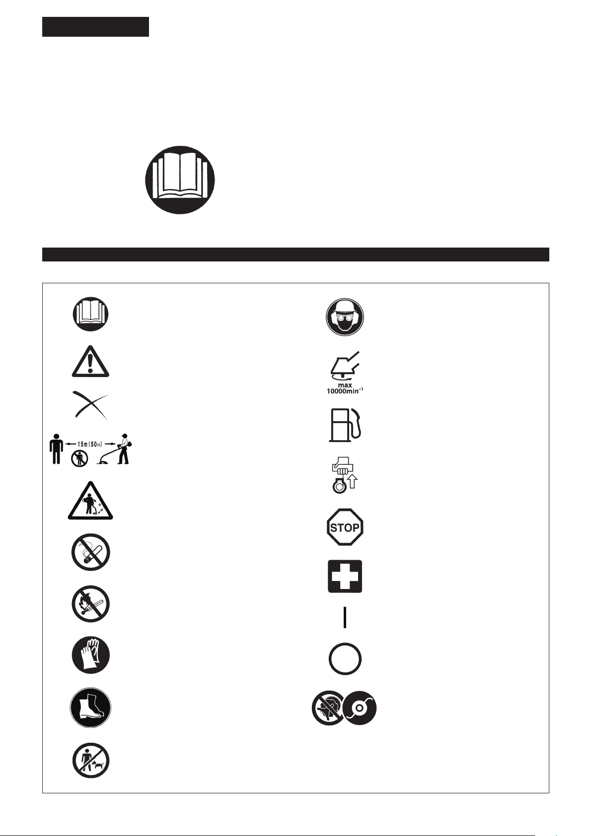
Wear protective helmet, eye and ear
protection.
Take particular care and attention!
Forbidden!
Keep distance!
Flying object hazard!
No smoking!
No open ame!
Top permissible tool speed
Fuel (Gasoline)
Engine-manual start
Emergency stop
First Aid
ON/START
Protective gloves must be worn!
Wear sturdy boots with nonslip soles.
Steeltoed safety boots are recommended!
Keep the area of operation clear of all
persons and pets!
2
OFF/STOP
Never use metal blades
Page 3
360°
SAFETY INSTRUCTIONS
General Instructions
Read this instruction manual to become familiar with handling of the –
equipment. Users insufciently informed will risk danger to themselves as
well as others due to improper handling.
It is recommended only to lend the equipment to people who have proven to –
be experienced.
Always hand over the instruction manual.
First users should ask the dealer for basic instructions to familiarize oneself –
with the handling of string trimmers.
Children and young persons aged under 18 years must not be allowed to –
operate this equipment. Persons over the age of 16 years may however
use the device for the purpose of being trained while under supervision of a
qualied trainer.
Use with the utmost care and attention. –
Operate only if you are in good physical condition. Perform all work calmly –
and carefully. The user has to accept liability for others.
Never use this equipment after consumption of alcohol or drugs, or if feeling –
tired or ill.
National regulation can restrict the use of the machine. –
Intended use of the machine
This equipment is only intended for cutting grass and light weeds. It should –
not be used for any other purpose such as edging or hedge cutting as this
may cause injury.
Personal protective equipment
The clothing worn should be functional and appropriate, i.e. it should be tight- –
tting but not cause hindrance. Do not wear either jewelry or clothing which
could become entangled with bushes or shrubs.
In order to avoid either head-, eye-, hand- or foot injuries as well as to protect –
your hearing the following protective equipment and protective clothing must
be used during operation.
Always wear a helmet where there is a risk of falling objects. The protective –
helmet (1) is to be checked at regular intervals for damage and is to be
replaced at the latest after 5 years. Use only approved protective helmets.
The visor (2) of the helmet (or alternatively goggles) protects the face from –
ying debris and stones. During operation always wear goggles, or a visor to
prevent eye injuries.
Wear adequate noise protection equipment to avoid hearing impairment (ear –
muffs (3), ear plugs etc.).
The work overalls (4) protect against ying stones and debris. –
We strongly recommend that the user wears work overalls.
Gloves (5) are part of the prescribed equipment and must always be worn –
during operation.
When using the equipment, always wear sturdy shoes (6) with a non-slip –
sole. This protects against injuries and ensures a good footing.
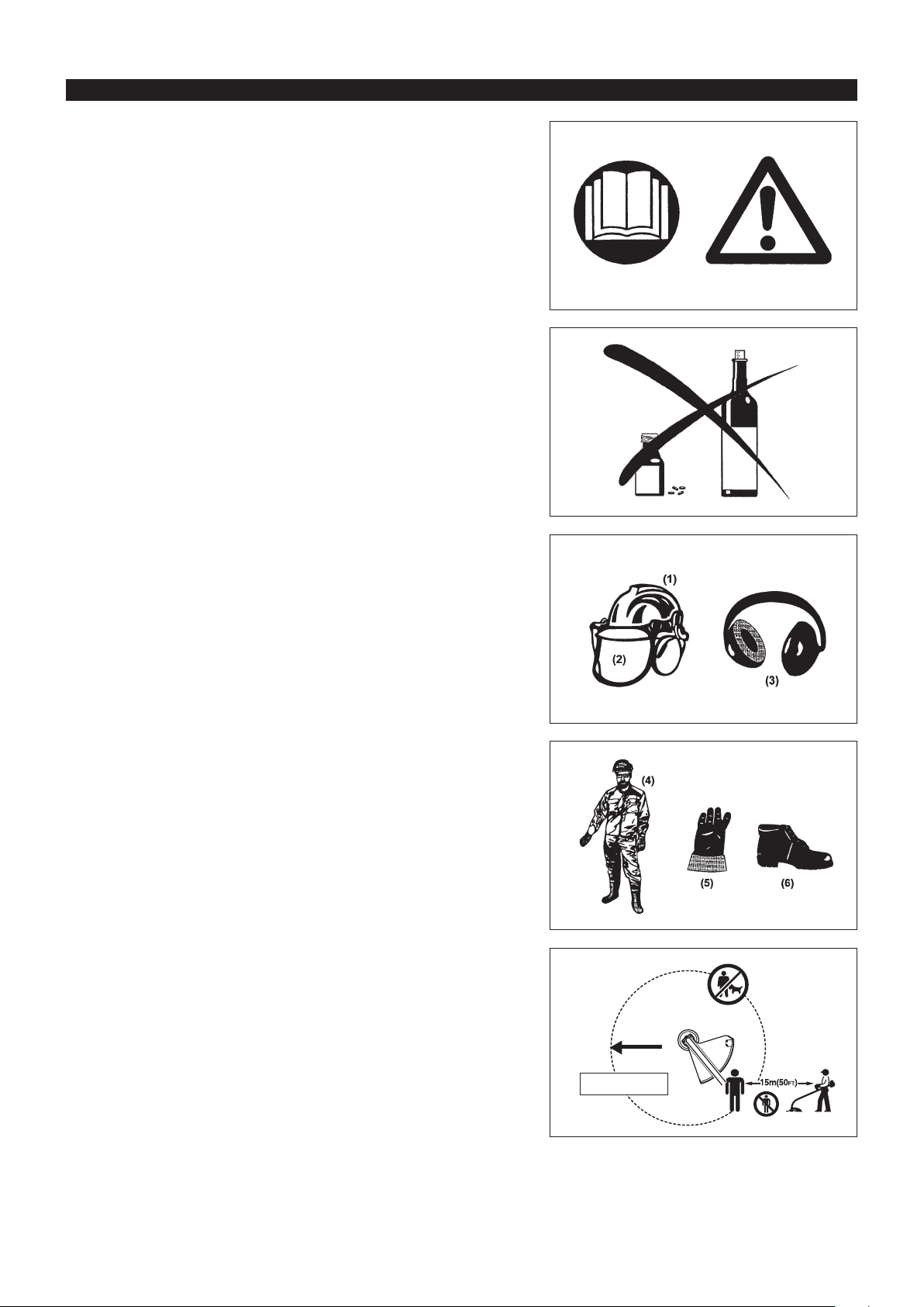
Starting up the Petrol String Trimmer
Please make sure that there are no children or other people within a working –
range of 15 meters (50 ft), also pay attention to any animals in the working
vicinity.
Before use always check the equipment is safe for operation: –
Check the security of the cutting attachment, the throttle lever for easy action
and check for proper functioning of the throttle lever lock.
Rotation of the cutting attachment during idling speed is not allowed. Check –
with your dealer for adjustment if in doubt. Check for clean and dry handles
and test the function of the start/stop switch.
Diagrammatic gure
15 Meters
3
Page 4
Start the Petrol String Trimmer only in accordance with the instructions. –
Do not use any other methods for starting the engine! –
Use the Petrol String Trimmer and the tools only for such applications as –
specied.
Only start the engine, after the entire assembly is done. Operation of the –
device is only permitted after all the appropriate accessories are attached!
Before starting make sure that the cutting attachment has no contact with –
hard objects such as branches, stones etc. as the cutting attachment will
revolve when starting.
The engine is to be switched off immediately in case of any engine problems. –
Should the cutting attachment hit stones or other hard objects, immediately –
switch off the engine and inspect the cutting attachment.
Inspect the cutting attachment at short regular intervals for damage (detection –
of hairline cracks by means of tapping-noise test).
If the equipment gets heavy impact or fall, check the condition before –
continuing work. Check the fuel system for fuel leakage and the controls
and safety devices for malfunction. If there is any damage or doubt, ask our
authorized service center for the inspection and repair.
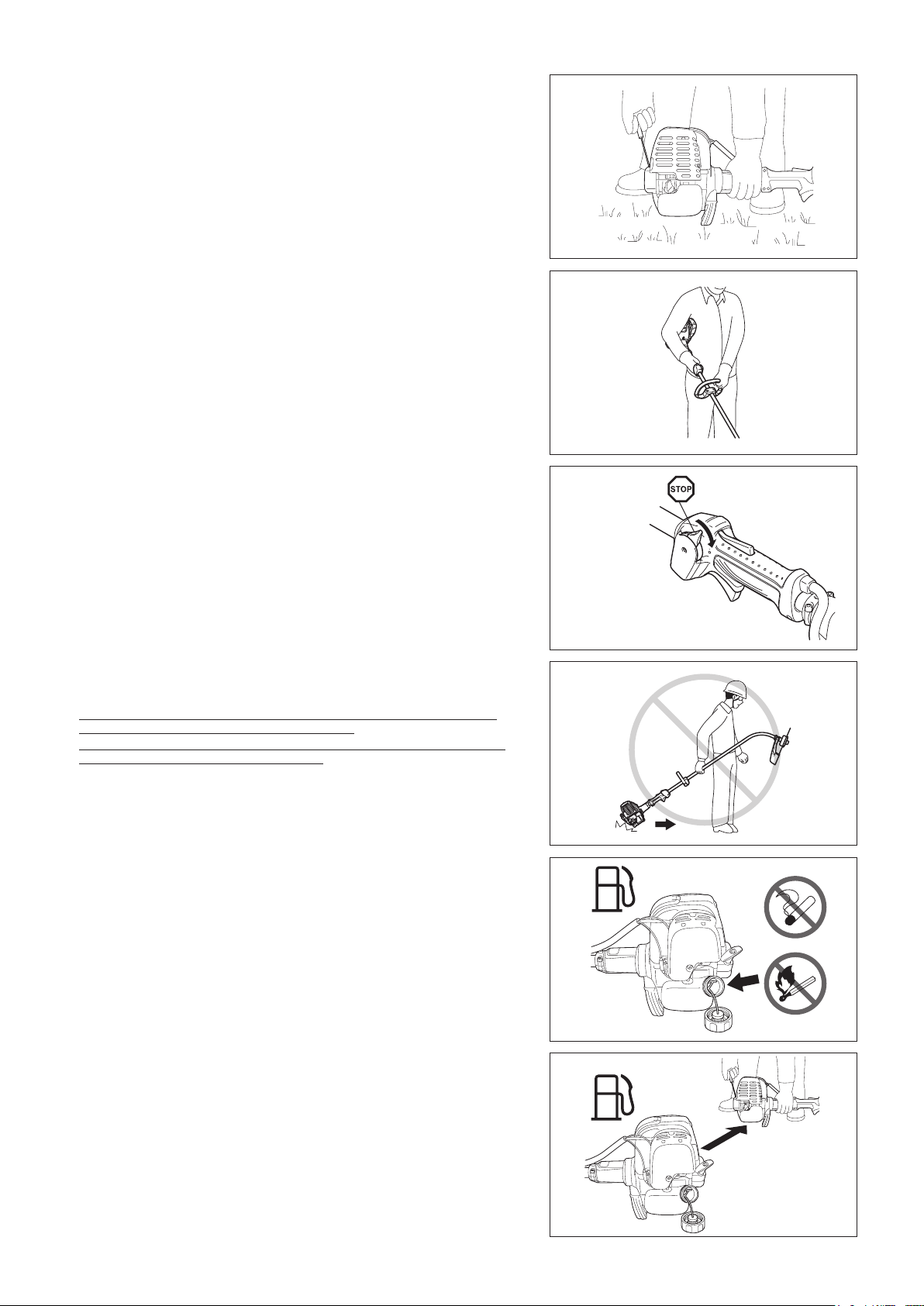
During operation always hold the Petrol String Trimmer with both hands. –
Never hold the Petrol String Trimmer with one hand during use.
Always ensure a safe footing.
Operate the equipment in such a manner as to avoid inhalation of the exhaust –
gases. Never run the engine in enclosed rooms (risk of gas poisoning).
Carbon monoxide is an odorless gas.
Switch off the engine when resting and when leaving the equipment –
unattended, and place it in a safe location to prevent danger to others or
damage to the machine.
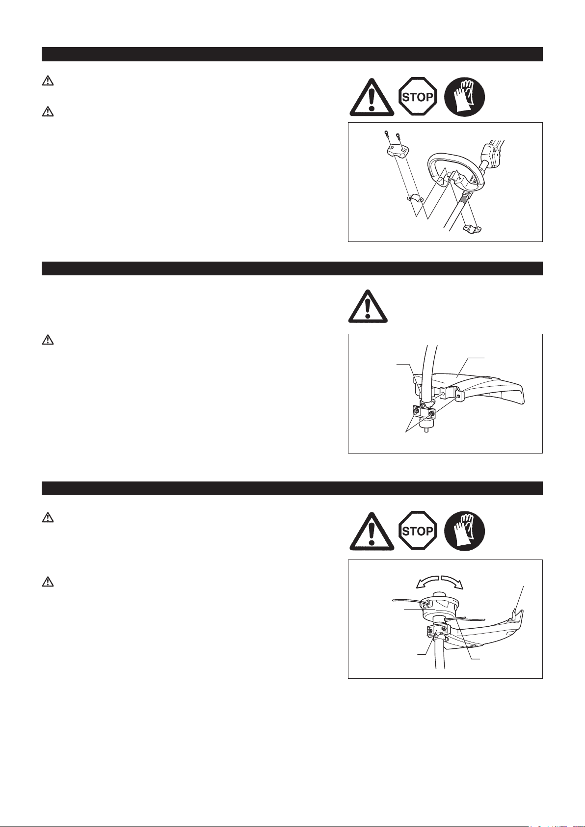
Never put the hot Petrol String Trimmer onto dry grass or onto any –
combustible materials.
Always install the approved cutting attachment guard onto the equipment –
before starting the engine. Otherwise contact with the cutting attachment may
cause serious injury.
All protective installations and guards supplied with the machine must be –
used during operation.
Never operate the engine with faulty exhaust mufer. –
Shut off the engine during transport. –
Ensure safe position of the equipment during car transportation to avoid fuel –
leakage.
When transporting, ensure that the fuel tank is completely empty. –
When unloading the equipment from the truck, never drop the Engine to the –
ground or this may severely damage the fuel tank.
Except in case of emergency, never drop or cast the equipment to the ground –
or this may severely damage the equipment.
Remember to lift the entire equipment from the ground when moving the –
equipment. Dragging the fuel tank is highly dangerous and will cause damage
and leakage of fuel, possibly causing re.
Resting•
Transport•
Refueling•
Maintenance•
Tool replacement•
Refueling
Shut off the engine during refueling, keep away from open ames and do not –
smoke.
Avoid skin contact with mineral oil products. Do not inhale fuel vapor. Always –
wear protective gloves during refueling. Change and clean protective clothing
at regular intervals.
Take care not to spill either fuel or oil in order to prevent soil contamination –
(environmental protection). Clean the Petrol String Trimmer immediately after
fuel has been spilt.
Avoid any fuel contact with your clothing. Change your clothing instantly if –
fuel has been spilt on it (to prevent clothing catching re).
Inspect the fuel cap at regular intervals making sure that it can be securely –
fastened and does not leak.
Carefully tighten the fuel tank cap. Change location to start the engine (at –
least 3 meters away from the place of refueling).
Never refuel in closed rooms. Fuel vapors accumulate at ground lever (risk of –
explosions).
Only transport and store fuel in approved containers. Make sure the fuel –
stored is not accessible to children.
4
3 meters
Page 5
Method of operation
Only use in good light and visibility. During the winter season beware of –
slippery or wet areas, ice and snow (risk of slipping). Always ensure a safe
footing.
Never cut above waist height. –
Never stand on a ladder. –
Never climb up into trees to perform cutting operation. –
Never work on unstable surfaces. –
Remove sand, stones, nails etc. found within the working range. –
Before commencing cutting, the cutting attachment must have reached full –
working speed.
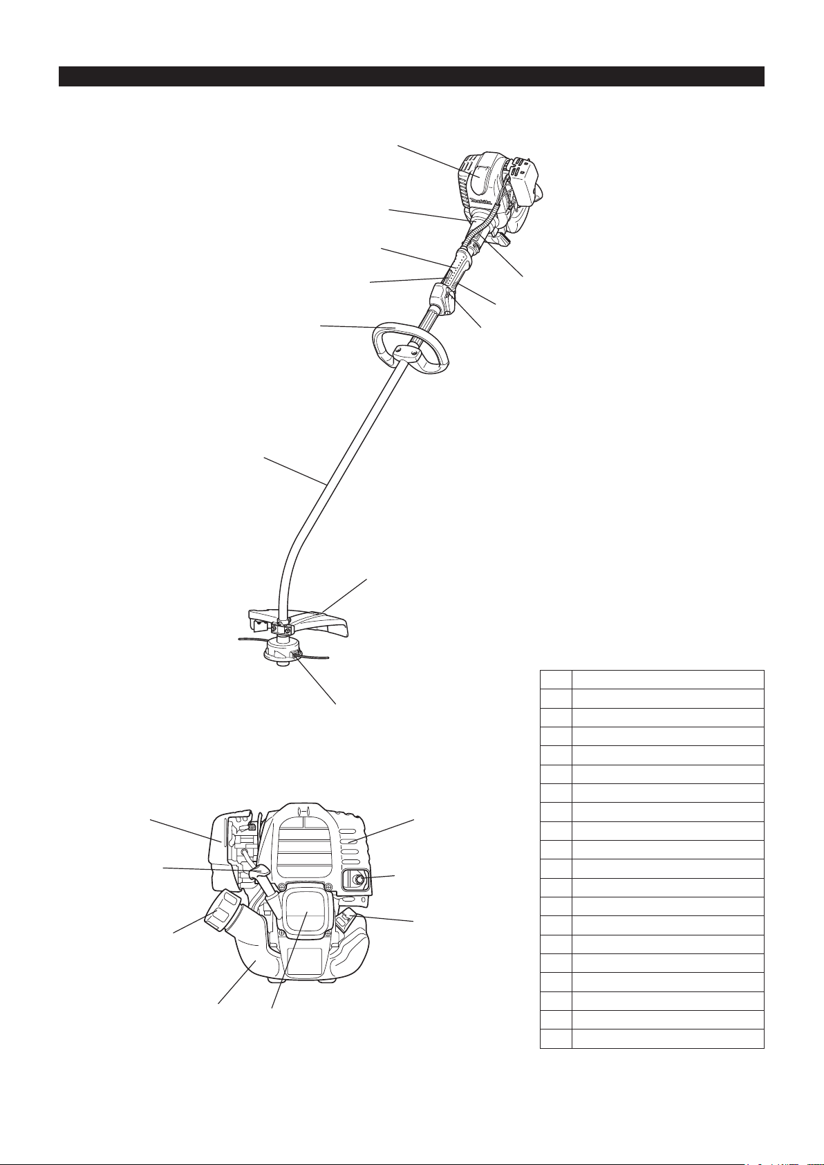
Swing the Petrol String Trimmer evenly. –
If grass or branches get caught between the cutting attachment and guard,
always stop the engine before cleaning. Otherwise unintentional attachment
rotation may cause serious injury.
Take a rest to prevent loss of control caused by fatigue. We recommend to –
take a 10 to 20-minute rest every hour.
Cutting attachments
Never use metal blades including metal multi-piece pivoting chains and ail –
blades. Otherwise blade contact may cause serious injury.
Vibration
People with poor circulation who are exposed to excessive vibration may –
experience injury to blood vessels or the nervous system. Vibration may
cause the following symptoms to occur in the ngers, hands or wrists: “Falling
asleep” (numbness), tingling, pain, stabbing sensation, alteration of skin color
or of the skin. If any of these symptoms occur, see a physician!
To reduce the risk of “white nger disease”, keep your hands warm during –
operation and well maintain the equipment and accessories.
Maintenance instructions
Have your equipment serviced by our authorized service center, always using –
only genuine replacement parts. Incorrect repair and poor maintenance can
shorten the life of the equipment and increase the risk of accidents.
The condition of the equipment, in particular of the cutting attachment of the –
protective devices must be checked before commencing work.
Turn off the engine and remove spark plug connector when replacing cutting –
attachments, and also when cleaning the cutter or cutting attachment.
Pay attention to the environment. Avoid unnecessary throttle operation for –
less pollution and noise emissions. Adjust the carburetor correctly.
Clean the equipment at regular intervals and check that all screws and nuts –
are well tightened.
Never service or store the equipment in the vicinity of naked ames. –
Always store the equipment in locked rooms and with an emptied fuel tank. –
Observe the relevant accident prevention instructions issued by the relevant trade associations and by the insurance companies.
Do not perform any modications to the equipment as this will endanger your safety.
The performance of maintenance or repair work by the user is limited to those activities as described in the instruction manual. All other work is
to be done by an Authorized Service Agent. Use only genuine spare parts and accessories released and supplied by MAKITA.
Use of non-approved accessories and tools means increased risk of accidents.
MAKITA will not accept any liability for accidents or damage caused by the use of non-approved cutting attachments and xing devices of cutting
attachments, or accessories.
First Aid
In case of accident make sure that a rst-aid box is available in the vicinity of
the cutting operations. Immediately replace any item taken from the rst aid box.
When asking for help, please give the following
information:
Place of accident –
What happened –
Number of injured persons –
Kind of injuries –
Your name –
5
Page 6

TECHNICAL DATA ER2550LH
Model
Dimensions: length x width x height (without cutting attachment) inch (mm) 64” X 11-3/8” X 18-1/4” (1,623 X 290 X 464)
Cutting diameter inch (mm) 16”-1/4” (412)
Mass (without plastic guard and cutting attachment) lbs (kg) 10.8 (4.9)
Volume (fuel tank) .oz (L) 16.9 (0.5)
Volume (oil reservoir) .oz (L) 2.7 (0.08)
Engine displacement cu.in (cm
Maximum engine performance hp (kw) 1.0 (0.71) at 7,000 rpm
Engine speed at recommended max. spindle speed RPM (1/min) 10,000
Maximum rotational frequency of the spindle RPM (1/min) 7,750
Idling speed RPM (1/min) 3,000
Clutch engagement speed RPM (1/min) 3,750
Carburetor type WALBRO WYL
Ignition system type Solid state ignition
Spark plug type NGK CMR4A
Electrode gap inch (mm) 1/32” (0.7-0.8)
Fuel Automobile gasoline
Engine Oil
(For Canada)
NOTE: This spark ignition system complies with the Canadian standard ICES-002.
3
) 1.49 (24.5)
SAE 10W-30 oil of API Classication,
Class SF or higher (4-stroke engine for automobile)
ER2550LH
Loop handle
6
Page 7
DESIGNATION OF PARTS
15
14
13
10
9
8
7
5
4
11
12
3
17
16
2
1
6
18
19
15
14
13
10
9
8
7
5
4
11
12
ER2550LH
GB DESIGNATION OF PARTS
1 Fuel tank
2 Rewind starter
3 Air cleaner
4 I-O switch (on/off)
5 Spark plug
6 Exhaust mufer
7 Clutch case
8 Rear grip
9 Lock-off lever
10 Handle
11 Throttle lever
12 Control cable
13 Shaft
14 Protector (Cutting attachment guard)
15 Nylon cutting head
16 Fuel tank cap
17 Starter knob
18 Exhaust pipe
19 Oil gauge
7
Page 8
MOUNTING OF HANDLE
CAUTION: Before doing any work on the equipment, always stop the
engine and pull the spark plug connector off the spark plug.
Always wear protective gloves!
CAUTION: Start the engine only after having assembled it completely.
For machines with loop handle
Fix the loop handle on the shaft as shown. –
Make sure that the spacer on the shaft pipe is located between the grip –
assembly and the other grip. Do not remove or shrink the spacer.
NOTE: In some countries, the spacer is not provided with the tool. In that case,
align the handle to further side of the line which is indicated by the
arrow marks.
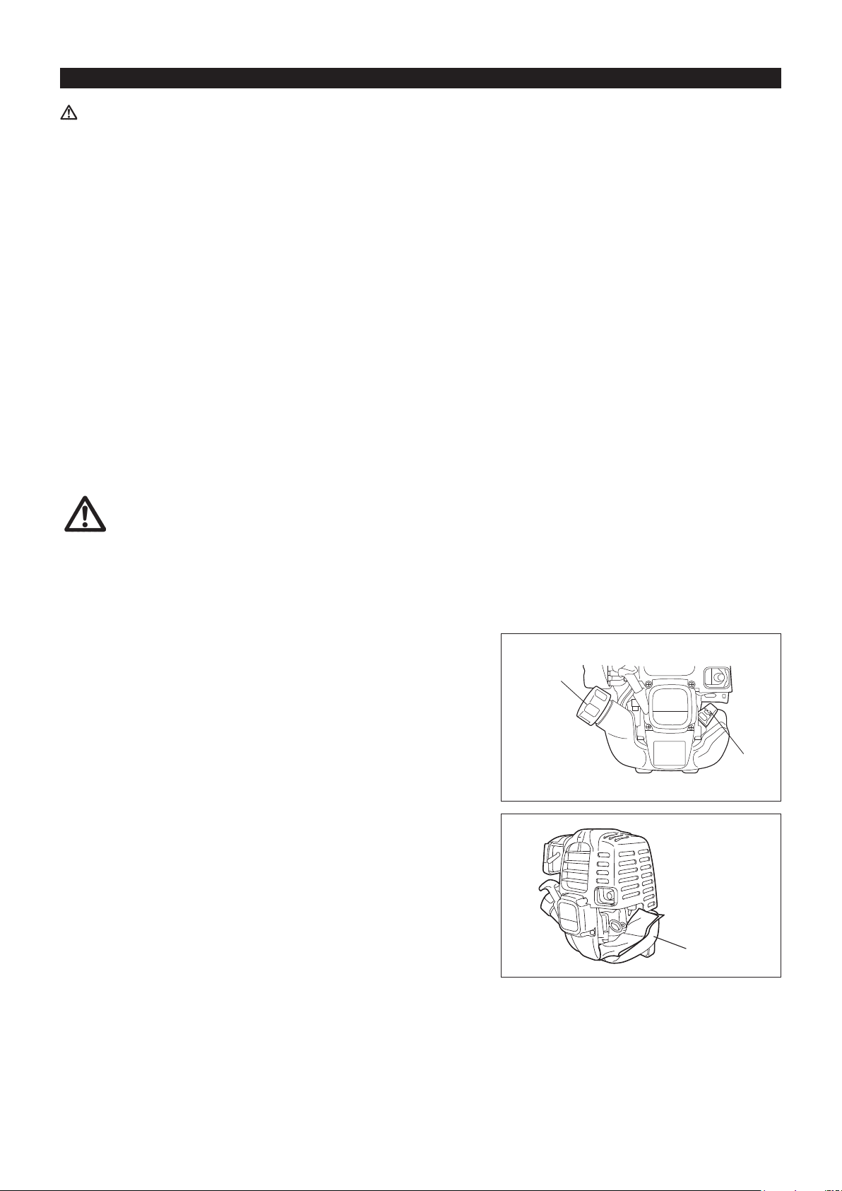
MOUNTING OF PROTECTOR
To meet the applicable safety provisions, only the tool/protector
combinations as indicated in the table must be used.
CAUTION: Do not touch the cord cutter on the protector. Touching the cord
cutter with bare hands may result in injury.
The protector must be installed to maintain the nylon-cutting-cord length and
protect the operator from thrown stones and debris. Install the protector as the
following steps.
Cord cutter
Protector
1. Set the protector so that the rib on the shaft ts into the groove on the
protector.
2. Tighten two bolts.
MOUNTING OF NYLON CUTTING HEAD
WARNING: Never use cutting blades.
Be sure to use genuine MAKITA nylon cutting head.
If the nylon cutting head hits against a stone during operation, stop the –
engine and check the nylon cutting head immediately.
CAUTION: Do not touch the cord cutter on the protector. Touching the cord
cutter with bare hands may result in injury.
Mount a nylon cutting head as the following steps.
1. Insert the lock key through the hole on the clamp. Rotate them with pushing
the lock key in until they are locked.
2. Screw a nylon cutting head onto the shaft by turning it clockwise. Make sure
that it is mounted securely.
3. Remove the lock key.
To remove the nylon cutting head, turn it counterclockwise.
Bolts
Nylon cutting
head
Clamp
Tighten Loosen
Cord cutter
Lock key
8
Page 9
BEFORE START OF OPERATION
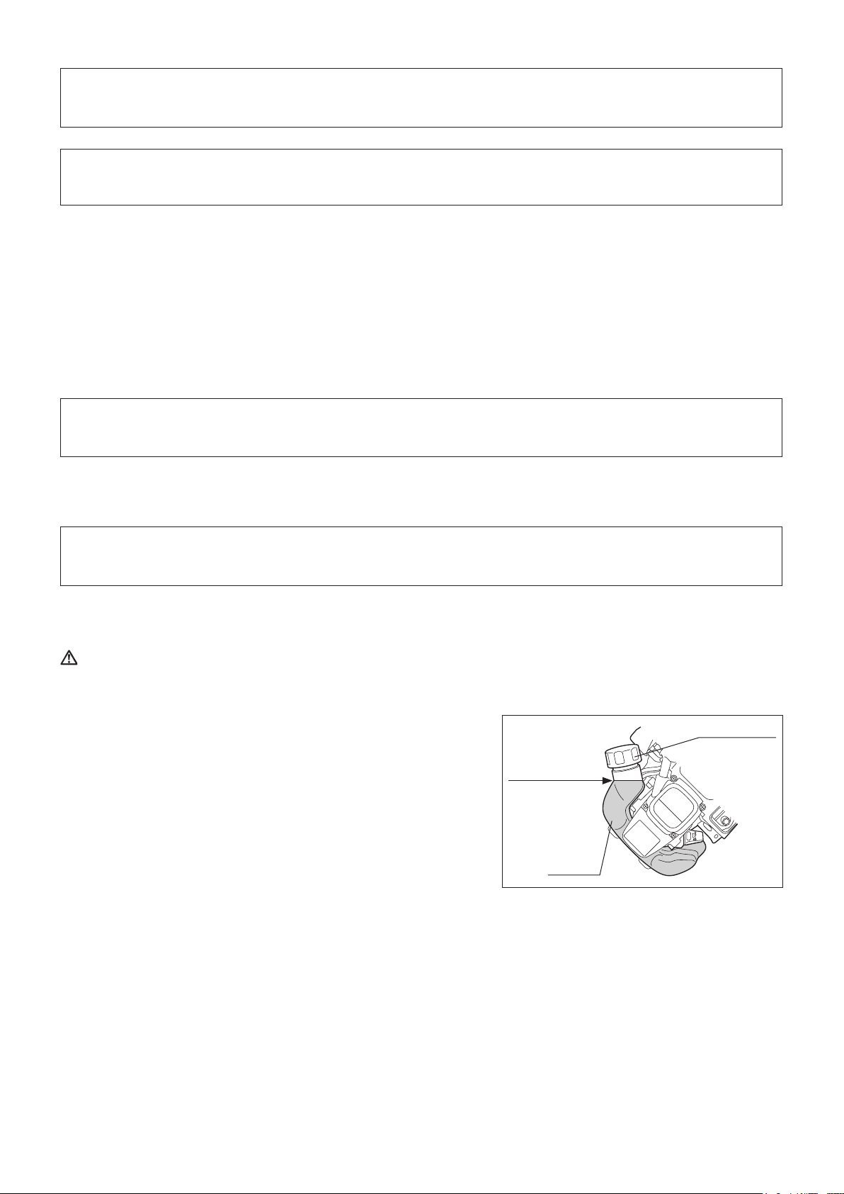
Inspectionandrellofengineoil
Perform the following procedure, with the engine cooled down. –
While keeping the engine level, remove the oil gauge, and conrm that the oil is lled within the upper and lower limit marks. –
When the oil is in short in such a way that the oil gauge touches the oil only by its tip, in particular with the oil gauge remaining inserted in the
crankcase without screwing-in (Fig. 1), rell new oil near the port (Fig. 2).
For reference, the oil rell time is about 10h (10 times or 10 tanks of oil rell). –
If the oil changes in color or mixes with dirt, replace it with new one. (For the interval and method of replacement, refer to P. 14)
Recommended oil: SAE 10W-30 oil of API Classication, Class SF or higher (4-stroke engine for automobile)
Oil volume: Approx. 0.08L
NOTE: If the engine is not kept upright, oil may go into around the engine, and may be relled excessively.
If the oil is lled above the limit, the oil may be contaminated or may catch re with white smoke.
Point 1 in Replacement of oil: “Oil gauge”
Remove dust or dirt near the oil rell port, and detach the oil gauge. –
Keep the detached oil gauge free of sand or dust. Otherwise, any sand or dust adhering to the oil gauge may cause irregular oil circulation –
or wear on the engine parts, which will result in troubles.
As an example to keep the oil gauge clean, it is recommended to insert the oil gauge on its knob side into the engine cover, as shown in –
Fig. 3.
Upper limit (Edge
of oil rell port)
If oil adheres around
this tip, rell new oil.
Fig. 1 Fig. 2 Fig. 3
(1) Keep the engine level, and detach the oil gauge.
(2) Fill oil up to the edge of the oil rell port. (Refer to Fig. 2.)
Feed oil with the lubricant rell container.
Oil gauge
(3) Securely tighten the oil gauge. Insufcient tightening may cause oil leakage.
9
Page 10
Note
Do not replace oil with the engine in a tilted position.•
Filling with oil while engine is tilted leads to overlling which causes oil contamination and/or white smoke.•
Point 2 in Replacement of oil: “If oil spills out”
If oil spills out between the fuel tank and engine main unit, the oil is sucked into through the cooling air intake port, which will contaminate –
the engine. Be sure to wipe out spilt oil before start of operation.
REFUELING
Handling of fuel
It is necessary to handle fuel with utmost care. Fuel may contain substances similar to solvents. Refueling must be performed in a sufciently
ventilated room or in the open air. Never inhale fuel vapor, and keep fuel away from you. If you touch fuel repeatedly or for a long time, the
skin becomes dry, which may cause skin disease or allergy. If fuel enters into the eye, clean the eye with fresh water. If your eye remains still
irritated, consult your doctor.
Storage period of fuel
Fuel should be used up within a period of 4 weeks, even if it is kept in a special container in a well-ventilated shade.
Otherwise, fuel may deteriorate in one day.
STORAGE OF MACHINE AND REFILL TANK
Keep the machine and tank at a cool place free from direct sunshine. –
Never keep the fuel in a car. –
Fuel
The engine is a four-stroke engine. Be sure to use an unleaded automobile gasoline 87 or higher octane ((R+M)/2). It may contain no more than
10% alcohol (E-10).
Points for fuel
Never use a gasoline mixture which contains engine oil. Otherwise, it will cause excessive carbon accumulation or mechanical troubles. –
Use of deteriorated oil will cause irregular startup. –
Refueling
WARNING: INFLAMMABLES STRICTLY PROHIBITED
Gasoline used: Unleaded automobile gasoline, 87 or higher octane. No more
than 10% alcohol (E-10).
Loosen the tank cap a little so that there will be no difference in atmospheric –
pressure.
Detach the tank cap, and refuel, discharging air by tilting the fuel tank so –
that the refuel port will be oriented upward. (Never rell fuel full to the oil rell
port.)
Wipe well the periphery of the tank cap to prevent foreign matter from –
entering into the fuel tank.
After refueling, securely tighten the tank cap. –
If there is any aw or damage on the tank cap, replace it.•
The tank cap is consumable, and therefore should be renewed every two to •
three years.
Fuel tank cap
Fuel upper limit
Fuel tank
10
Page 11
POINTS IN OPERATION AND HOW TO STOP
Observe the applicable accident prevention regulations!
STARTING
Move at least 3 m away from the place of refueling. Place the unit on the ground taking care that the cutting attachment does not come into
contact with the ground or any other objects.
A: Cold start
1) Set this machine on a at space.
2) Set the I-O switch (1) to OPERATION.
3) Primer pump
Continue to push the primer pump until fuel enters into the primer pump. (In
general, fuel enters into the primer pump by 7 to 10 pushes.)
If the primer pump is pushed excessively, an excess of gasoline returns to
the fuel tank.
OPERATION
Carburetor
Lock-off lever
STOP
Throttle lever
(1)
High speed
Low speed
Primer pump
4) Recoil starter
Pull the start knob gently until it is hard to pull (compression point). Then,
return the start knob, and pull it strongly.
Never pull the rope to the full. Once the start knob is pulled, never release
your hand immediately. Hold the start knob until it returns to its original
point.
5) Warm-up operation
Continue warm-up operation for 2 to 3 minutes.
NOTE: In case of excessive fuel intake (ooding), remove the spark plug and pull the starter handle slowly to remove excess fuel. Also, dry the
electrode section of the spark plug.
B: Startup after warm-up operation
1) Push the primer pump repeatedly.
2) Keep the throttle lever at the idling position.
3) Pull the recoil starter strongly.
4) If it is difcult to start the engine, open the throttle by about 1/3.
Attention in Operation
When the engine is operated upside down, white smoke may come out from the mufer.
11
Page 12
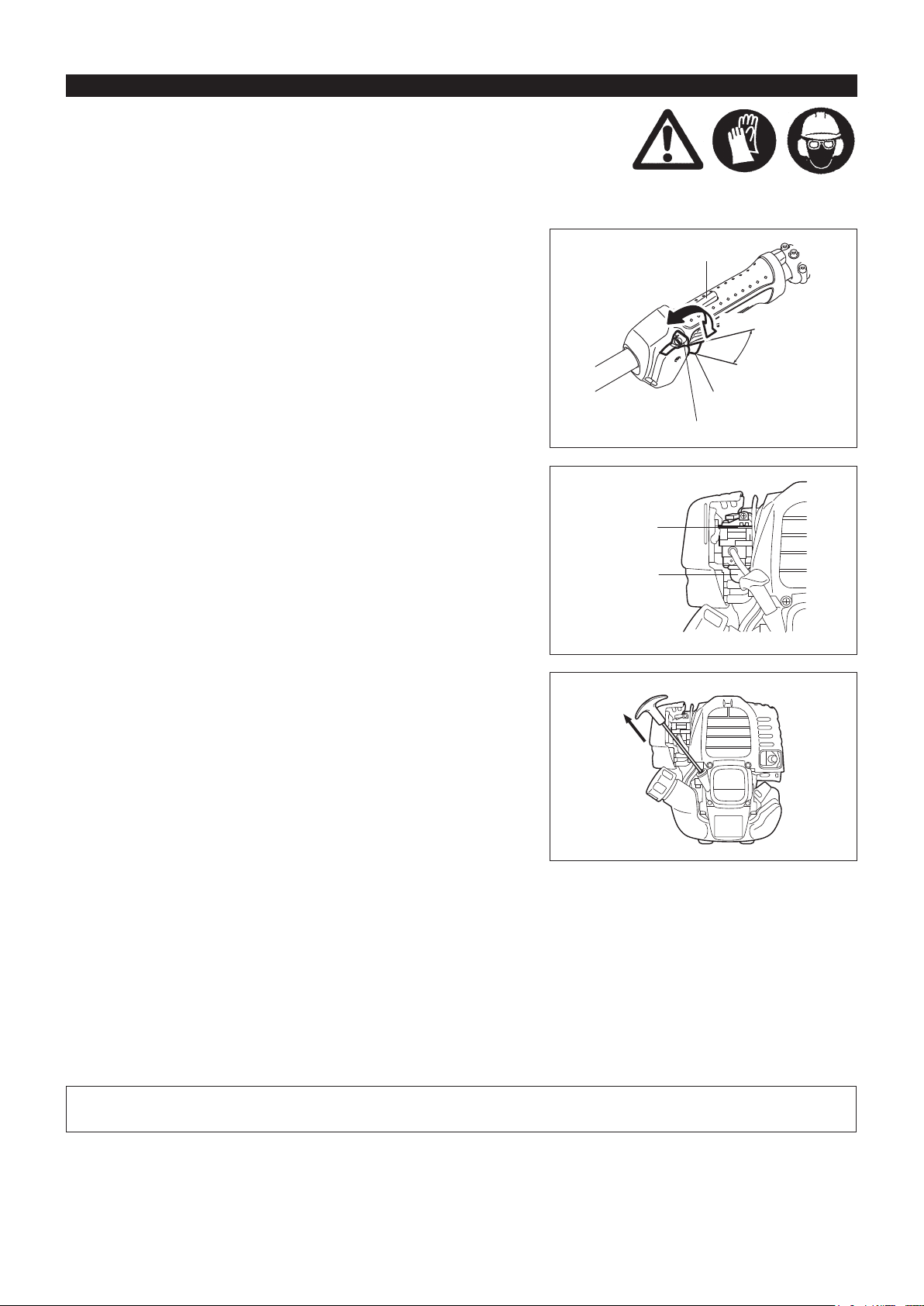
At times, such as winter, when starting the engine
is difcult
Operate choke lever with the following procedure when starting engine.
After implementing startup steps 1) to 3), set choke lever to the CLOSE •
position.
Implement startup step 4) and start engine.•
Once engine starts, set choke lever to the OPEN position.•
Implement startup step 5) and complete warm up.•
CLOSE
CAUTION: If a bang (explosive sound) is heard and the engine stops, or
the just-started engine stalls before the choke lever is operated,
return the choke lever to the OPEN position, and pull the starter
knob a few times again to start the engine.
CAUTION: If the choke lever is left in the CLOSE position, and the starter
knob merely pulled repeatedly, too much fuel will be sucked in,
and the engine will become difcult to start.
STOPPING
1) Release the throttle lever (2) fully, and when the engine rpm has lowered,
set the I-O switch to STOP the engine will now stop.
2) Be aware that the cutting head may not stop immediately and allow it to
slow down fully.
OPEN
STOP
(2)
(1)
ADJUSTMENT OF LOW-SPEED ROTATION (IDLING)
When it is necessary to adjust the low-speed rotation (idling), perform it by the carburetor adjusting screw.
CHECKUP OF LOW-SPEED ROTATION
Set the low-speed rotation to 3,000 min –
If it is necessary to change the low speed rotation (idle) speed, use a phillips
head screw driver on the screw illustrated on the right.
Turn the adjusting screw to the right, and the engine rotation will increase. –
Turn the adjusting screw to the left, and the engine rotation will drop.
The carburetor is generally adjusted before shipment. If it is necessary to –
readjust it, please contact Authorized Service Agent.
-1
.
Adjusting
screw
Carburetor
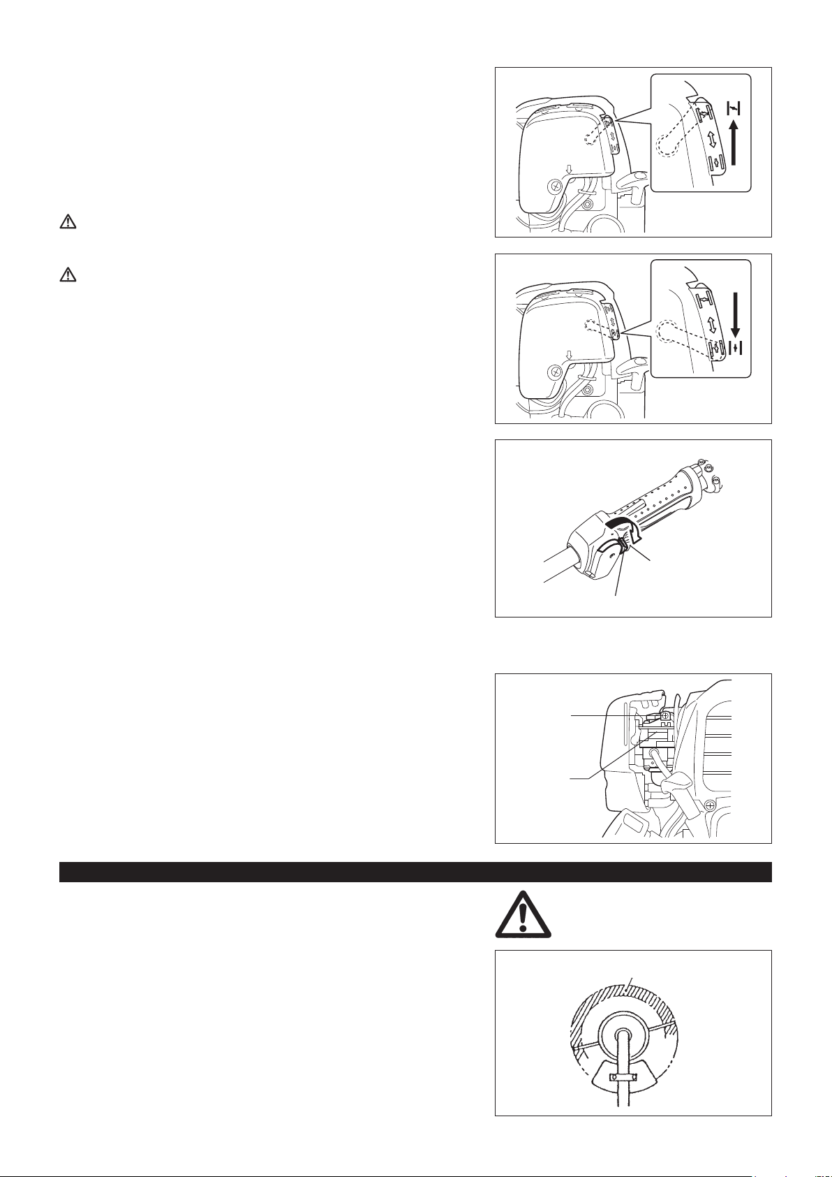
THE NYLON CUTTING HEAD
During operation, use the tip of the nylon cutting cord for cut.
Feeding the nylon cutting cord
As the nylon cutting cord is worn and shortened with the cutting operation, the
operator needs to feed it manually.
Most effective cutting area
To feed the nylon cutting cord, tap the nylon cutting head on the ground while it
rotates around 6,000 min
NOTE: If the nylon cutting cord does not feed out, rewind it.
-1
.
12
Page 13
80 mm
100 mm
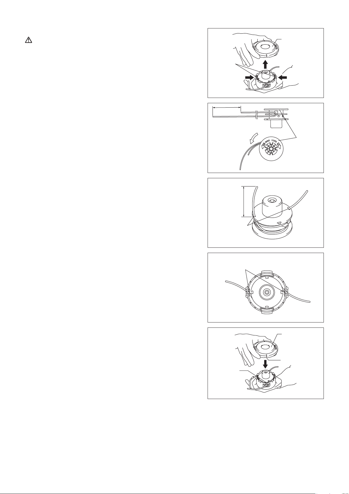
Replacing the nylon cord
WARNING:
Press inward on the housing latches and lift upward to remove the cover.
Discard any of the remaining nylon cord.
Hook the middle of the new nylon cord to the notch located at the center of the
spool between the 2 channels provided for the nylon cord. One side of the cord
should be about 80 mm longer than the other side.
Wind both ends rmly around the spool in the direction marked on the head for
right hand direction indicated by RH.
Wind all but about 100 mm of the cords, leaving the ends temporarily hooked
through a notch on the side of the spool.
Make sure that the cover of the nylon cutting head is secured
to the housing properly as described below. Failure to properly
secure the cover may cause the nylon cutting head to y apart
resulting in serious personal injury.
Latches
For right hand
rotation
Cover
PressPress
Spool
Mount the spool in the housing so that the grooves and protrusions on the spool
match up with those in the housing. Now, unhook the ends of the cord from their
temporary position and feed the cords through the eyelets to come out of the
housing.
Align the protrusion on the underside of the cover with the slots of the eyelets.
Then push cover rmly onto the housing to secure it. Make sure the latches fully
spread in the cover.
Notches
Eyelets
Cover
Protrusion
(Not shown)
Slot of
eyelet
13
Page 14
SERVICING INSTRUCTIONS
CAUTION: Before doing any work on the equipment, always stop the engine and pull the plug cap off the spark plug (see “checking the
Always wear protective gloves!
To ensure a long service life and to avoid any damage to the equipment, the following servicing operations should be performed at regular
intervals.
spark plug”).
Daily checkup and maintenance
Before operation, check the machine for loose screws or missing parts. Pay particular attention to the tightness of the nylon cutting head. –
Before operation, always check for clogging of the cooling air passage and the cylinder ns. –
Clean them if necessary.
Perform the following work daily after use: –
Clean the equipment externally and inspect for damage.•
Clean the air lter. When working under extremely dusty conditions, clean the lter the several times a day.•
Check the nylon cutting head for damage and make sure it is rmly mounted.•
Check that there is sufcient difference between idling and engagement speed to ensure that the cutting attachment is at a standstill while •
the engine is idling (if necessary reduce idling speed).
If under idling conditions the tool should still continue to run, consult your nearest Authorized Service Agent.
Check the functioning of the I-O switch, the lock-off lever, the throttle lever, and the lock button. –
REPLACEMENT OF ENGINE OIL
Deteriorated engine oil will shorten the life of the sliding and rotating parts to a great extent. Be sure to check the period and quantity of
replacement.
ATTENTION: In general, the engine main unit and engine oil still remain hot just after the engine is stopped. In replacement of oil,
conrm that the engine main unit and engine oil are sufciently cooled down. Otherwise, there may remain a risk of
scald.
NOTE:Iftheoillledabovethelimit,itmaybecontaminatedormaycatchrewithwhitesmoke.
Interval of replacement: Initially, every 20 operating hours, and subsequently every 50 operating hours
Recommended oil: SAE10W-30 oil of API Classication SF Class or higher (4-stroke engine oil for automobile)
In replacement, perform the following procedure.
1) Conrm that the tank cap is tightened securely.
2) Detach the oil gauge.
Keep the oil gauge free from dust or dirt.
3) Place waste or paper near the oil rell port.
Fuel tank cap
Oil gauge
Waste or paper
14
Page 15
4) Detach the oil gauge, and drain oil, tilting the main unit toward the oil rell
port.
Drain oil in a container for orderly disposal.
5) Keep the engine level, and feed new oil up to the edge of the oil rell port.
In rell, use a lubricant rell container.
6) After rell, securely tighten the oil gauge. Insufcient tightening of the oil
gauge will lead to oil leakage.
POINTS ON OIL
Never discard replaced engine oil in garbage, earth or sewage ditch. Disposal of oil is regulated by law. In disposal, always follow the –
relevant laws and regulations. For any points remaining unknown, contact Authorized Service Agent.
Oil will deteriorate even when it is kept unused. Perform inspection and replacement at regular intervals (replace with new oil every –
6 months).
CLEANING OF AIR CLEANER
DANGER: INFLAMMABLES STRICTLY PROHIBITED
Interval of Cleaning and Inspection: Daily (every 10 operating hours)
Turn the choke lever to the full close side, and keep the carburetor off from –
dust or dirt.
Remove the air cleaner cover-xing bolts. –
Pull the cover lower side and detach the air cleaner cover. –
If oil adheres to the element (sponge), squeeze it rmly. –
For heavy contamination: –
1) Remove the element (sponge), immerse it in warm water or in waterdiluted
neutral detergent, and dry it completely.
2) Clean the element (felt) with gasoline, and dry it completely.
Before attaching the element, be sure to dry it completely. Insufcient drying –
of the element may lead to difcult startup.
Wipe out with waste cloth, oil adhering around the air cleaner cover and plate –
breather.
Immediately after cleaning is nished, attach the cleaner cover and tighten it –
with xing bolts. (In remounting, rst place the upper claw, and then the lower
claw.)
Points in Handling Air Cleaner Element
Clean the element several times a day, if excessive dust adheres to it. –
If operation continues with the element remaining not cleared of oil, oil in –
the air cleaner may fall outside, resulting in oil contamination.
Plate
Element (sponge)
Air cleaner cover
Breather part
Element (felt)
Fixing bolt
Pick this part and remove
the element (felt).
15
Page 16
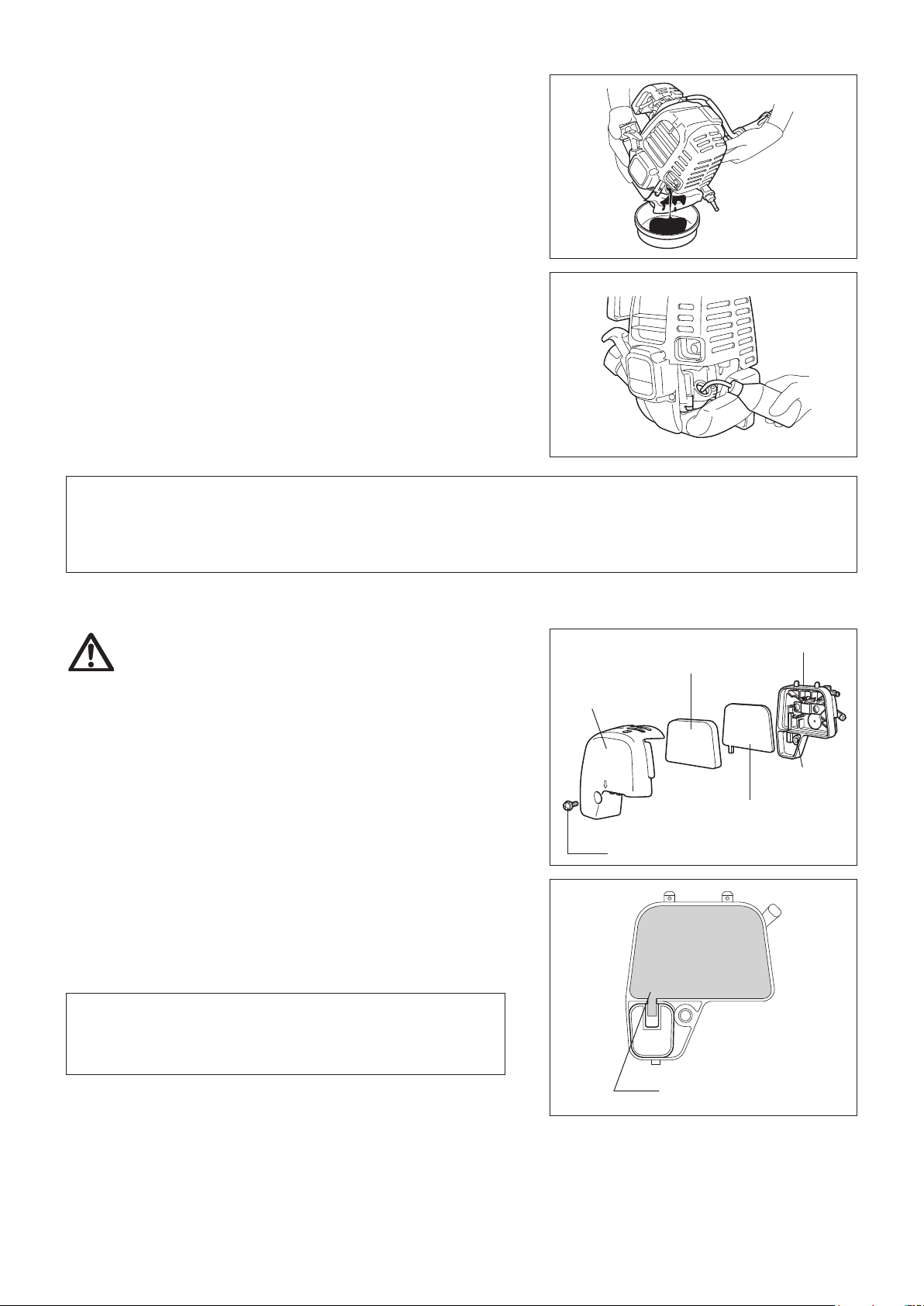
CHECKING THE SPARK PLUG
Only use the supplied universal wrench to remove or to install the spark plug. –
The gap between the two electrodes of the spark plug should be 0.7 - 0.8 mm –
(0.028” - 0.032”). If the gap is too wide or too narrow, adjust it. If the spark
plug is clogged or contaminated, clean it thoroughly or replace it.
CAUTION: Never touch the spark plug connector while the engine is
running (danger of high voltage electric shock).
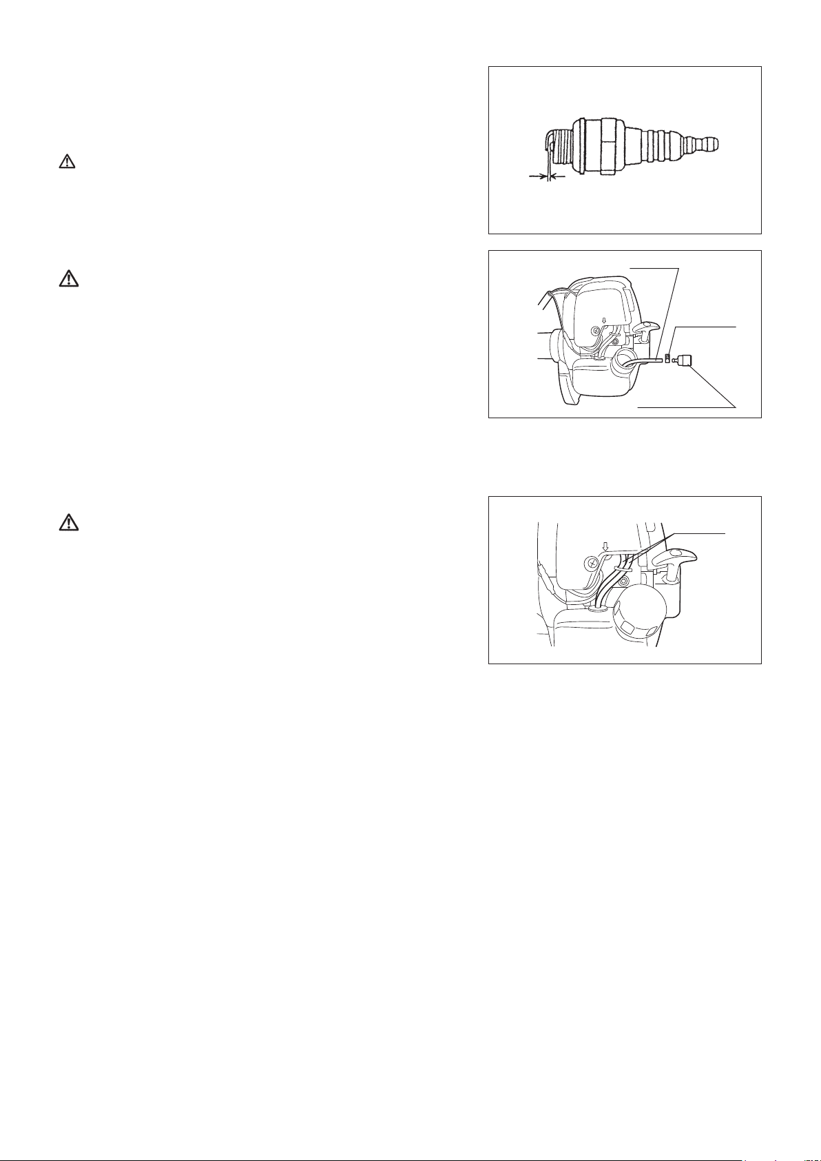
CLEANING OF FUEL FILTER
WARNING: INFLAMMABLES STRICTLY PROHIBITED
Interval of Cleaning and Inspection: Monthly (every 50 operating hours)
Suction head in the fuel tank
The fuel lter (1) of the suction head is used to lter the fuel required by the –
carburetor.
A periodical visual inspection of the fuel lter is to be conducted. For that –
purpose open the tank cap, use a wire hook and pull out the suction head
through the tank opening. Filters found to have hardened, been polluted or
clogged up are to be replaced.
Insufcient fuel supply can result in the admissible maximum speed being –
exceeded. It is therefore important to replace the fuel lter at least quarterly to
ensure satisfactory fuel supply to the carburetor.
REPLACEMENT OF FUEL PIPE
CAUTION: INFLAMMABLES STRICTLY PROHIBITED
Interval of Cleaning and Inspection: Daily (every 10 operating hours)
Replacement: Annually (every 200 operating hours)
Replace the fuel pipe every year, regardless of operating frequency. Fuel
leakage may lead to re.
If any leakage is detected during inspection, replace the fuel pipe immediately.
0.7 mm - 0.8 mm
(0.028” - 0.032”)
Fuel pipe
Hose clamp
Fuel lter (1)
Fuel pipe
INSPECTION OF BOLTS, NUTS AND SCREWS
Retighten loose bolts, nuts, etc. –
Check for fuel and oil leakage. –
Replace damaged parts with new ones for safety operation. –
CLEANING OF PARTS
Keep the engine always clean. –
Keep the cylinder ns free of dust or dirt. Dust or dirt adhering to the ns will –
cause piston seizure.
REPLACEMENT OF GASKETS AND PACKINGS
In reassembling after the engine is dismounted, be sure to replace the gaskets and packings with new ones.
Any maintenance of adjustment work that is not included and described in this manual is only to be performed by Authorized Service Agents.
16
Page 17

STORAGE
WARNING: When draining the fuel, be sure to stop the engine and make sure that the engine
cools down.
Just after stopping the engine, it may still be hot with possibility of burns,
inammabilityandre.
ATTENTION: When the machine is kept out of operation for a long time, drain up all fuel from the
fuel tank and carburetor, and keep it at a dry and clean place.
Drain fuel from the fuel tank and carburetor according to the following procedure: –
1) Remove the fuel tank cap, and drain fuel completely.
If there is any foreign matter remaining in the fuel tank, remove it completely.
2) Pull out the fuel lter from the rell port using a wire.
3) Push the primer pump until fuel is drained from there, and drain fuel coming into the fuel tank.
4) Put the lter to the fuel tank, and securely tighten the fuel tank cap.
5) Then, continue to operate the engine until it stops.
Remove the spark plug, and drip several drops of engine oil through the spark plug hole. –
Gently pull the starter handle so that engine oil will spread over the engine, and attach the spark plug. –
During storage, keep the rod horizontal or keep the machine upright with the cutting attachment side oriented upward. (In this case, pay full –
attention to prevent the machine from falling.)
Never store the machine with the cutting attachment side oriented downward. Lubricating oil may spill out.
Keep the drained fuel in a special container in a well-ventilated shade. –
Attention after long-time storage
Before startup after long-time shutdown, be sure to replace oil (refer to P 14). Oil will deteriorate while the machine is kept out of –
operation.
Fault location
Fault System Observation Cause
Engine not starting or with
difculty
Warm start problems Tank lled ignition spark
Engine starts but dies Fuel supply Tank lled Incorrect idling adjustment, carburetor contaminated
Insufcient performance Several systems may
Ignition system Ignition spark O.K. Fault in fuel supply or compression system, mechanical
defect
No ignition spark STOP-switch operated, wiring fault or short circuit, spark
plug or connector defective, ignition module faulty
Fuel supply Fuel tank lled Incorrect choke position, carburetor defective, fuel supply
line bent or blocked, fuel dirty
Compression No compression when
pulled over
Mechanical fault Starter not engaging Broken starter spring, broken parts inside of the engine
existing
Engine idling poor Air lter contaminated, carburetor contaminated, mufer
simultaneously be
affected
Cylinder bottom gasket defective, crankshaft seals
damaged, cylinder or piston rings defective or improper
sealing of spark plug
Carburetor contaminated, have it cleaned
Fuel tank vent defective, fuel supply line interrupted,
cable or STOP-switch faulty
clogged, exhaust duct in the cylinder clogged
17
Page 18

Item
Operating time
Before
operation
After
lubrication
Daily
(10h)
30h 50h 200h
Shutdown/
rest
Corres-
ponding P
Engine oil
Inspect/clean
Replace
Tightening parts
(bolt, nut)
Inspect
Clean/inspect
Fuel tank
Drain fuel
Throttle lever Check function
Stop switch Check function
Cutting attachment Inspect
Low-speed rotation Inspect/adjust
Air cleaner Clean
Ignition plug Inspect
Cooling air inlet Clean/inspect
Inspect
Fuel pipe
Replace
Fuel lter Clean/replace
9
1
*
14
16
—
3
*
17
—
12
8
12
15
16
16
16
2
*
—
16
Clearance between air intake
valve and air discharge valve
Adjust
Engine overhaul
Carburetor Drain fuel
*1 Perform initial replacement after 20h operation.
*2 For the 200 operating hour inspection, request Authorized Service Agent or a machine shop.
*3 After emptying the fuel tank, continue to run the engine and drain fuel in the carburetor.
2
*
2
*
3
*
—
—
17
18
Page 19

TROUBLESHOOTING
Before making a request for repairs, check for trouble by yourself. If any abnormality is found, control your machine according to the description
of this manual. Never tamper or dismount any part contrary to the description. For repairs, contact Authorized Service Agent or local dealership.
State of abnormality Probable cause (malfunction) Remedy
Failure to operate primer pump Push 7 to 10 times
Low pulling speed of starter rope Pull strongly
Lack of fuel Feed fuel
Clogged fuel lter Clean
Broken fuel tube Straighten fuel tube
Deteriorated fuel Deteriorated fuel makes starting more difcult.
Replace with new fuel. (Recommended
replacement: 1 month)
Excessive suction of fuel Set throttle lever from medium speed to high
speed, and pull starter handle until engine
starts. Once engine starts, nylon cutting
Engine does not start
Detached plug cap Attach securely
Contaminated spark plug Clean
Abnormal clearance of spark plug Adjust clearance
Other abnormality of spark plug Replace
Abnormal carburetor Make request for inspection and maintenance.
Starter rope cannot be pulled Make request for inspection and maintenance.
Abnormal drive system Make request for inspection and maintenance.
Insufcient warm-up Perform warm-up operation
Choke lever is set to “CLOSE” although
Engine stops soon
Engine speed does not increase
The cutting attachment does not rotate.
Stop engine immediately!
The unit vibrates abnormally.
Stop engine immediately!
The cutting attachment does not stop.
Stop engine immediately!
Engine does not stop
Run engine at idling, and set choke lever
to CLOSE
The nylon cutting cord does not feed. The cord is used up or tangled in the spool. Rewind the cord.
The nylon cutting cord is not cut off at the
correct length.
When the engine does not start after warm-up operation:
If there is no abnormality found for the check items, open the throttle by about 1/3 and start the engine.
engine is warmed up.
Clogged fuel lter Clean
Contaminated or clogged air cleaner Clean
Abnormal carburetor Make request for inspection and maintenance.
Abnormal drive system Make request for inspection and maintenance.
The cutting attachment is not tightened
securely.
A twig is caught between the cutting
attachment and the protector.
The drive system does not work properly. Ask Makita authorized service center to
The cutting attachment is broken. Replace the cutting attachment with new one.
The cutting attachment is not tightened
securely.
One end of nylon cutting cord has been
broken and the nylon cutting head got
unbalanced.
The drive system does not work properly. Ask Makita authorized service center to
The power unit does not work properly. Refer to the instruction manual of the power
Detached connector Attach securely
Abnormal electric system Make request for inspection and maintenance.
The cord cutter on the protector is damaged
or missing.
The cord extends past the protector. Rewind the cord.
head starts rotating. Pay full attention to
nylon cutting head.
If engine will not start still, remove spark plug,
make electrode dry, and reassemble them as
they originally are. Then, start as specied.
Set to “OPEN”
Tighten the cutting attachment securely.
Remove the foreign matter.
inspect and repair it.
Tighten the cutting attachment securely.
Feed the nylon cutting cord with tapping the
nylon cutting head on the ground.
inspect and repair it.
unit.
Ask Makita authorized service center to
replace the cord cutter.
19
Page 20

Français
Merci d’avoir acheté l’équipement de jardinage motorisé MAKITA. Nous
sommes heureux de vous recommander ce produit MAKITA qui est le fruit
d’un long programme de développement et de nombreuses années de
connaissances et d’expérience.
Veuillez lire ce document, il décrit en détail les performances remarquables de
cette machine. Il vous aidera à obtenir les meilleurs résultats possibles de votre
produit MAKITA.
PICTOGRAMMES
Vous verrez les pictogrammes suivants en lisant le manuel d’instructions.
Lire le manuel d’instructions et respecter
les avertissements et mesures de
sécurité!
Table des matières Page
Pictogrammes..............................................................20
Consignes de sécurité .................................................21
Données techniques ....................................................24
Désignation des pièces ...............................................25
Montage de la poignée ................................................26
Montage du protecteur ................................................26
Montage de la tête à ls nylon .....................................26
Avant utilisation ...........................................................27
Remarques concernant le fonctionnement
et l’arrêt de la machine ................................................29
Tête à ls nylon ...........................................................30
Instructions d’entretien ................................................32
Entreposage ................................................................35
Casque de protection, protections oculaire
et auditive obligatoires.
Faites particulièrement attention!
Interdit!
Ne pas s’approcher!
Danger de projections!
Défense de fumer!
Flamme nue interdite!
Vitesse d’outil maximale autorisée
Carburant (essence)
Démarrage manuel du moteur
Arrêt d’urgence
Premiers soins
MARCHE/DÉMARRAGE
Gants de protection obligatoires!
Portez des chaussures solides avec
semelle antidérapante.
Il est conseillé de porter des chaussures
avec embout de sécurité!
Zone de travail interdite aux individus et
aux animaux!
20
ARRÊT/COUPURE MACHINE
N’utilisez jamais de lames métalliques
Page 21

360°
CONSIGNES DE SÉCURITÉ
Consignes générales
Lisez ce manuel d’instructions an de vous familiariser avec le –
fonctionnement de l’équipement. S’ils ne sont pas sufsamment informés, les
utilisateurs qui manipulent la machine de façon incorrecte représentent un
danger pour eux-mêmes comme pour les autres.
Il est recommandé de prêter l’équipement seulement à des personnes l’ayant –
déjà utilisé.
Remettez toujours le manuel d’instructions avec la machine.
Les utilisateurs inexpérimentés doivent demander des instructions de –
base au vendeur an de se familiariser avec la manipulation d’une
débroussailleuse.
Les enfants et les mineurs ne doivent pas être autorisés à utiliser cet –
équipement. Les individus âgés de plus de 16 ans peuvent toutefois utiliser
la machine en vue d’apprentissage, mais toujours sous la surveillance d’une
personne qualiée.
Utilisez l’équipement avec le maximum de soin et d’attention. –
Utilisez l’équipement seulement si vous êtes en bonne forme physique. –
Manipulez délicatement et soigneusement la machine. L’utilisateur doit
endosser la responsabilité du fait d’autrui.
N’utilisez jamais cet équipement après avoir consommé de l’alcool ou de la –
drogue, ou encore si vous vous sentez fatigué ou malade.
Les réglementations nationales peuvent limiter l’utilisation de la machine. –
Utilisation normale de la machine
Cet équipement est conçu pour couper de l’herbe. Il ne doit en aucun cas –
être utilisé dans un autre but, comme le dressage de bordures ou la taille de
haies. Cela représente un risque de blessure.
Équipement de protection personnel
La tenue portée doit être fonctionnelle et appropriée, autrement dit elle doit –
être ajustée et ne pas entraver les mouvements. Ne portez pas de bijoux ni
de vêtements qui pourraient s’accrocher dans les buissons ou les arbustes.
An d’éviter les blessures à la tête, aux yeux, aux mains ou aux pieds et –
de protéger votre ouïe, vous devez porter l’équipement et les vêtements de
protection indiqués ci-dessous lorsque vous utilisez l’équipement.
Portez toujours un casque s’il y a un risque de chute d’objets. Le casque de –
protection (1) doit être inspecté fréquemment en vue d’éventuels dommages
et doit être remplacé au moins tous les 5 ans. Utilisez uniquement des
casques de protection homologués.
La visière-écran (2) du casque (ou à défaut les lunettes étanches) protège le –
visage des projections de débris et de pierres. Portez toujours des lunettes
étanches ou une visière lorsque vous utilisez l’équipement, an de prévenir
les blessures aux yeux.
Portez un équipement anti-bruit adéquat an d’éviter une perte auditive –
(protège-oreilles (3), bouchons d’oreilles, etc.).
La combinaison de travail (4) vous protège des projections de débris et de –
pierres.
Il est vivement conseillé à l’utilisateur de porter une combinaison de travail.
Les gants (5) font partie de l’équipement réglementaire et doivent toujours –
être portés lors de l’utilisation de l’équipement.
Lorsque vous utilisez l’équipement, portez toujours des chaussures (6) –
robustes dotées d’une semelle antidérapante. Cela vous préservera des
blessures et vous assurera une bonne stabilité.
Démarrage de la débroussailleuse thermique
Veillez à éloigner les enfants ou toute autre personne dans un périmètre de –
travail de 15 mètres (50 pieds) et faites également attention aux animaux
présents dans cette zone.
Assurez-vous toujours que l’équipement est en bonne condition avant de –
l’utiliser.
Vériez la sécurité du dispositif de coupe, ainsi que le bon fonctionnement du
levier d’accélérateur et de son verrouillage.
La rotation du dispositif de coupe en fonctionnement de ralenti est –
impossible. Vériez le réglage auprès de votre vendeur en cas de doute.
Vériez que les poignées sont propres et sèches, et testez le fonctionnement
du commutateur marche/arrêt.
Schéma de
représentation
15 mètres
21
Page 22

Suivez strictement les instructions pour démarrer la débroussailleuse –
thermique.
Ne démarrez pas le moteur d’une autre façon. –
N’utilisez la débroussailleuse thermique et ses outils que pour l’utilisation à –
laquelle ils sont destinés.
Ne démarrez le moteur qu’une fois que la machine est totalement montée. Le –
fonctionnement de la machine n’est possible qu’une fois tous les accessoires
correctement xés!
Avant le démarrage, veillez à ce que le dispositif de coupe ne soit pas en –
contact avec des objets durs tels que des branches, des pierres, etc., étant
donné qu’il amorcera la rotation au démarrage.
Vous devez couper immédiatement le moteur s’il présente un –
dysfonctionnement.
Si le dispositif de coupe heurte des pierres ou des objets durs, coupez –
immédiatement le moteur et inspectez le dispositif de coupe.
Inspectez fréquemment le dispositif de coupe en vue d’éventuels dommages –
(détection de craquelures grâce à un test de bruit de battement).
Si l’équipement tombe ou heurte violemment une surface, vériez son –
état avant de poursuivre l’utilisation. Recherchez une éventuelle fuite du
système d’alimentation et un éventuel dysfonctionnement des dispositifs de
commande et de sécurité. En cas de dommage avéré ou suspecté, adressezvous à un centre de services agréé pour une inspection et une réparation.
Tenez toujours la débroussailleuse thermique avec les deux mains en cours –
de fonctionnement.
Ne tenez jamais la débroussailleuse thermique d’une seule main lorsqu’elle
est en marche.
Assurez-vous toujours de votre stabilité.
Utilisez l’équipement de manière à éviter l’inhalation des gaz d’échappement. –
Ne faites jamais fonctionner le moteur dans une pièce fermée (risque
d’asphyxie au gaz). Le monoxyde de carbone est un gaz inodore.
Coupez le moteur lorsque vous cessez l’utilisation et que vous laissez –
l’équipement sans surveillance, puis rangez la machine dans un endroit sûr
an de ne pas l’endommager ni blesser qui que ce soit.
Ne placez jamais la débroussailleuse thermique chaude sur de l’herbe sèche –
ou sur tout matériau combustible.
Installez toujours le dispositif de protection du dispositif de coupe sur –
l’équipement avant de lancer le moteur. Si vous ne le faites pas, un contact
avec le dispositif de coupe peut entraîner des blessures graves.
Toutes les installations et dispositifs de protection fournis avec la machine –
doivent être utilisés au cours du fonctionnement.
Ne faites jamais tourner le moteur avec un silencieux d’échappement défectueux. –
Coupez le moteur durant le transport. –
Assurez-vous que l’équipement est positionné correctement lors du transport –
en voiture pour éviter toute fuite d’essence.
Lors du transport, assurez-vous que le réservoir d’essence est complètement vide. –
Lors du déchargement de l’équipement du camion, ne laissez jamais tomber –
le moteur sur le sol car cela pourrait endommager sérieusement le réservoir
d’essence.
Sauf en cas d’urgence, ne faites jamais tomber l’équipement ou ne le lancez –
pas par terre; cela risquerait de provoquer des dommages graves.
Ne traînez pas l’équipement sur le sol lorsque vous le transportez. Il est très –
dangereux de faire traîner le réservoir d’essence, cela pourrait l’endommager,
provoquer une fuite d’essence, voire même déclencher un incendie.
Pause•
Transport•
Remplissage•
Entretien•
Remplacement d’outil•
Remplissage
Coupez le moteur pendant le remplissage du réservoir, éloignez-vous de –
toute amme et ne fumez pas.
Évitez tout contact des produits pétroliers avec la peau. N’inhalez pas les –
vapeurs d’essence. Portez toujours des gants de protection pendant le
remplissage du réservoir. Changez et nettoyez souvent les vêtements de
protection.
Veillez à ne pas renverser l’essence ou l’huile an de ne pas contaminer les –
sols (protection de l’environnement). Nettoyez la débroussailleuse thermique
immédiatement si de l’essence a été renversée.
Évitez les projections d’essence sur vos vêtements. Changez immédiatement vos –
vêtements en cas de projection d’essence (pour éviter qu’ils ne s’enamment).
Inspectez régulièrement le bouchon du réservoir d’essence pour vous –
assurer qu’il se ferme correctement et qu’il ne fuit pas.
Serrez bien le bouchon du réservoir d’essence. Déplacez-vous pour démarrer –
le moteur (à au moins 3 mètres du lieu de remplissage du réservoir).
Ne remplissez jamais le réservoir dans une pièce fermée. Les vapeurs –
d’essence s’accumulent au ras du sol (risque d’explosions).
Ne transportez et ne conservez l’essence que dans des conteneurs –
appropriés. Veillez à conserver l’essence hors de portée des enfants.
22
3 mètres
Page 23

Mode de fonctionnement
Utilisez l’équipement seulement avec un bon éclairage et dans de bonnes –
conditions de visibilité. En hiver, faites attention aux sols glissants et aux
zones humides, à la glace et à la neige (risque de glissade). Assurez-vous
toujours de votre stabilité.
Ne réalisez jamais de coupe en tenant la machine plus haut que votre taille. –
Ne montez jamais sur une échelle. –
Ne réalisez jamais de coupe en étant perché dans un arbre. –
Ne travaillez pas sur des surfaces instables. –
Retirez le sable, les pierres, les clous, etc. qui se trouvent dans la zone –
d’utilisation de la machine.
Avant de commencer la coupe, le dispositif de coupe doit avoir atteint sa –
pleine vitesse de travail.
Balancez la débroussailleuse thermique régulièrement. –
Si de l’herbe ou des branches sont coincées entre le dispositif de coupe et
son dispositif de protection, coupez toujours le moteur avant de procéder au
nettoyage. Si vous ne le faites pas, une rotation accidentelle du dispositif peut
entraîner des blessures graves.
Faites des pauses an de ne pas perdre le contrôle à cause de la fatigue. Nous –
vous recommandons de vous reposer 10 à 20 minutes toutes les heures.
Dispositifs de coupe
N’utilisez jamais des lames métalliques, y compris les chaines multiples –
pivotantes métalliques et les lames à éaux. Si vous le faites, un contact
avec la lame peut entraîner des blessures graves.
Vibrations
Des détériorations au niveau des vaisseaux sanguins ou du système nerveux –
peuvent se produire chez des personnes souffrant de troubles circulatoires et
trop souvent soumises à des vibrations. Les symptômes pouvant apparaître
à la suite de vibrations au niveau des doigts, des mains ou des articulations
sont les suivants : engourdissement des membres, chatouillements, douleurs,
points et altération de la peau (notamment, le changement de couleur). Si
ces symptômes apparaissent, consultez un médecin.
Pour éviter le phénomène du « doigt mort », assurez-vous de garder vos –
mains au chaud durant l’utilisation de l’outil et de préserver le bon état de
l’outil et de ses accessoires.
Consignes d’entretien
Faites réparer votre équipement par nos centres de services agréés, –
qui n’utilisent que des pièces de rechange d’origine. Des réparations
mal exécutées et un mauvais entretien peuvent réduire la durée utile de
l’équipement et accroître les risques d’accident.
Vous devez vérier l’état de l’équipement, plus particulièrement du dispositif –
de coupe et des protections, avant de commencer à travailler.
Coupez le moteur et retirez le connecteur de la bougie d’allumage lorsque vous –
remplacez les dispositifs de coupe, et également lorsque vous les nettoyez.
Faites attention à l’environnement. Évitez tout fonctionnement inutile du –
papillon des gaz an de limiter la pollution et les nuisances sonores. Réglez
correctement le carburateur.
Nettoyez l’équipement à intervalles réguliers et vériez que toutes les vis et –
tous les écrous sont bien serrés.
Ne réparez ou n’entreposez jamais l’équipement à proximité de ammes nues. –
Entreposez toujours l’équipement dans une pièce fermée à clé avec le –
réservoir d’essence vide.
Respectez les consignes de prévention des accidents fournies par les associations professionnelles ainsi que par les compagnies d’assurance
concernées.
N’apportez aucune modication à l’équipement, cela vous mettrait en danger.
L’entretien ou les réparations réalisables par l’utilisateur sont ceux décrits dans le manuel d’instructions. Tout autre travail doit être réalisé par un
technicien agréé. N’utilisez que des pièces de rechange et accessoires fabriqués et vendus par MAKITA.
L’utilisation d’accessoires et outils non agréés accroît le risque d’accidents.
MAKITA décline toute responsabilité en cas d’accidents ou de dommages du fait de l’utilisation de dispositifs de coupe, de dispositifs de xation
de dispositifs de coupe ou d’accessoires non agréés.
Premiers soins
En cas d’accident, veillez à avoir une trousse de premiers soins non loin de
la zone de travail. Remplacez sans délai tout article utilisé dans la trousse de
premiers soins.
Si vous demandez de l’aide, veillez à donner les
informations suivantes :
Lieu de l’accident; –
Les conditions de l’accident; –
Le nombre de personnes blessées; –
Le type de blessure; –
Votre nom. –
23
Page 24

DONNÉES TECHNIQUES ER2550LH
Modèle
Dimensions : longueur x largeur x hauteur
(hors dispositif de coupe)
Diamètre de coupe pouce (mm) 16”-1/4” (412)
Poids
(hors dispositif de protection plastique et dispositif de coupe)
Volume (réservoir d’essence) oz liq (l) 16,9 (0,5)
Volume (réservoir d’huile) oz liq (l) 2,7 (0,08)
Cylindrée pouce cube (cm
Rendement maximal du moteur hp (kW) 1,0 (0,71) à 7 000 tr/min
Vitesse moteur à la vitesse de broche maximale recommandée TR/MIN (1/min) 10 000
Fréquence de rotation maximale de la broche TR/MIN (1/min) 7 750
Vitesse au ralenti TR/MIN (1/min) 3 000
Vitesse d’embrayage TR/MIN (1/min) 3 750
Carburateur type WALBRO WYL
Système d’allumage type Allumage transistorisé
Bougie d’allumage type NGK CMR4A
Distance entre les électrodes pouce (mm) 1/32” (0,7-0,8)
Carburant Essence automobile
Huile moteur
(Pour le Canada)
NOTE : Ce système d’allumage par étincelle de véhicule est conforme à la norme NMB-002 du Canada.
pouce (mm) 64” X 11-3/8” X 18-1/4” (1 623 X 290 X 464)
lb (kg) 10,8 (4,9)
3
) 1,49 (24,5)
SAE 10W-30 huile de classication API,
(moteur automobile à 4 temps)
ER2550LH
Poignée arceau
classe SF ou supérieure
24
Page 25

DÉSIGNATION DES PIÈCES
15
14
13
10
9
8
7
5
4
11
12
3
17
16
2
1
6
18
19
15
14
13
10
9
8
7
5
4
11
12
ER2550LH
F DÉSIGNATION DES PIÈCES
1 Réservoir d’essence
2 Démarreur à rappel
3 Filtre à air
4 Commutateur (marche/arrêt)
5 Bougie d’allumage
6 Silencieux d’échappement
7 Carter d’embrayage
8 Poignée arrière
9 Levier de sécurité
10 Poignée
11 Levier d’accélérateur
12 Câble de commande
13 Axe
Protecteur
14
(Dispositif de protection du
dispositif de coupe)
15 Tête à ls nylon
16 Bouchon du réservoir d’essence
17 Poignée de démarrage
18 Tuyau d’échappement
19 Jauge d’huile
25
Page 26

MONTAGE DE LA POIGNÉE
ATTENTION : Avant de manipuler l’équipement, coupez toujours le moteur
et retirez le connecteur de la bougie d’allumage.
Portez toujours des gants de protection!
ATTENTION : Ne démarrez le moteur qu’après l’avoir entièrement
assemblé.
Pour les machines avec poignée arceau
Fixez la poignée arceau sur l’axe comme indiqué. –
Assurez-vous que la pièce d’écartement de l’axe se trouve entre l’ensemble –
de la poignée et l’autre poignée. Ne réduisez pas et ne tassez pas la pièce
d’écartement.
REMARQUE : Dans certains pays, la pièce d’écartement n’est pas fournie avec
l’outil. Dans ce cas, alignez la poignée plus loin du côté de la
ligne indiquée par les èches.
MONTAGE DU PROTECTEUR
An de respecter les consignes de sécurité en vigueur, vous ne devez utiliser
que les ensembles outil/protecteur indiqués dans le tableau.
ATTENTION : Ne touchez pas le coupe-l du protecteur. Vous pourriez
vous blesser en touchant le coupe-l à mains nues.
Le protecteur doit être installé de façon à maintenir la longueur du l en nylon et
à protéger l’opérateur des projections de pierres et débris. Installez le protecteur
de la façon suivante.
Coupe-l
Protecteur
1. Placez le protecteur de sorte que les nervures de l’axe correspondent à la
rainure du protecteur.
2. Serrez les deux boulons.
MONTAGE DE LA TÊTE À FILS NYLON
AVERTISSEMENT : N’utilisez jamais de lames de coupe.
Assurez-vousd’utiliserunetêteàlsdenylonMAKITA
d’origine.
Si la tête à ls nylon heurte une pierre en cours de fonctionnement, coupez le –
moteur et vériez immédiatement l’état de la tête à ls nylon.
ATTENTION : Ne touchez pas le coupe-l du protecteur. Vous pourriez
vous blesser en touchant le coupe-l à mains nues.
Montez une tête à ls nylon de la façon suivante.
1. Insérez la clavette de verrouillage dans le trou du collier de xation. Faites-
les pivoter en enfonçant la clavette de verrouillage jusqu’à la butée.
2. Vissez une tête à ls nylon sur l’axe en tournant dans le sens horaire.
Veillez à ce qu’elle soit solidement montée.
3. Retirez la clavette de verrouillage.
Boulons
Tête à ls
nylon
Fixation
Serrer Desserrer
Coupe-l
Clavette de
verrouillage
Pour retirer la tête à ls nylon, tournez-la dans le sens antihoraire.
26
Page 27

AVANT UTILISATION
Inspection et remplissage de l’huile moteur
Procédez comme suit, une fois le moteur refroidi. –
Maintenez le moteur de niveau, retirez la jauge d’huile et assurez-vous que le niveau d’huile se trouve entre les limites supérieure et –
inférieure.
Lorsqu’il n’y a pas sufsamment d’huile et que seule l’extrémité de la jauge peut atteindre l’huile, notamment si la jauge est insérée dans le
carter du moteur sans être vissée (Fig. 1), rajoutez de l’huile par l’orice (Fig. 2).
Pour informations, le temps de remplissage de l’huile est d’environ 10 heures (10 remplissages ou un remplissage de 10 réservoirs d’huile). –
Si l’huile change de couleur ou se mélange à des impuretés, changez-la. (Pour connaître la fréquence et la méthode de remplacement,
reportez-vous à la page 32)
Huile recommandée : SAE 10W-30 huile de classication API, classe SF ou supérieure (moteur automobile à 4 temps)
Quantité d’huile : Environ 0,08 l
REMARQUE : Si le moteur n’est pas de niveau, l’huile peut se répandre dans le moteur et le remplissage peut être excessif.
Si vous mettez trop d’huile, elle peut être souillée ou s’enammer en dégageant une fumée blanche.
Remarque 1 concernant le changement d’huile : « Jauge d’huile »
Retirez la poussière ou les impuretés au niveau de l’orice de remplissage d’huile, puis détachez la jauge d’huile. –
Veillez à ce que la jauge d’huile n’entre pas en contact avec du sable ou de la poussière. Le sable ou la poussière adhérant à la jauge –
d’huile pourrait perturber la circulation de l’huile ou entraîner une usure des pièces moteur, provoquant des problèmes.
Pour garantir la propreté de la jauge d’huile, il est recommandé de l’insérer dans le couvercle du moteur en la tenant par sa poignée, –
comme indiqué sur la Fig. 3.
Limite supérieure
(Bord de l’orice de
remplissage d’huile)
Si de l’huile adhère
à cette extrémité,
rajoutez de l’huile.
Fig. 1 Fig. 2 Fig. 3
(1) Maintenez le moteur de niveau et détachez la jauge d’huile.
Jauge d’huile
(2) Versez de l’huile jusqu’au bord de l’orice de remplissage. (Reportez-vous à
la Fig. 2).
Versez l’huile à l’aide du acon de remplissage de lubriant.
(3) Serrez bien la jauge d’huile. Un bouchon d’huile insufsamment serré peut
fuir.
27
Page 28

Remarque
Ne versez pas d’huile lorsque le moteur est incliné.•
Verser de l’huile alors que le moteur est incliné entraîne un remplissage excessif, causant une contamination de l’huile et/ou une fumée •
blanche.
Remarque 2 concernant le changement d’huile : « Si l’huile déborde »
Si l’huile déborde entre le réservoir d’essence et le corps du moteur, elle sera aspirée par l’orice d’admission d’air de refroidissement et –
contaminera le moteur. Veillez à essuyer l’excédent d’huile avant de démarrer la machine.
REMPLISSAGE
Manipulation de l’essence
Vous devez manipuler l’essence avec une extrême précaution. L’essence peut contenir des substances telles que des solvants. Vous devez
procéder au remplissage dans une pièce sufsamment ventilée ou en plein air. Tenez-vous éloigné de l’essence et évitez d’en inhaler les
vapeurs. Si l’essence entre en contact plusieurs fois ou pendant longtemps avec votre peau, vous pourriez souffrir de sécheresse cutanée,
entraînant maladies de peau ou allergies. En cas de projection d’essence dans les yeux, rincez à l’eau claire. Si vos yeux restent irrités,
consultez un médecin.
Entreposage de l’essence
Vous devez utiliser l’essence dans un délai de 4 semaines, même si vous la conservez dans un conteneur spécial, dans un endroit ombragé et
bien ventilé.
Sinon, la qualité de l’essence pourrait être altérée.
ENTREPOSAGE DE LA MACHINE ET REMPLISSAGE DU RÉSERVOIR
Entreposez la machine et son réservoir dans un endroit frais non soumis à la lumière directe du soleil. –
Ne conservez jamais l’essence dans une voiture. –
Carburant
Le moteur est un moteur à quatre temps. Veillez à utiliser de l’essence automobile sans plomb, indice d’octane 87 ou plus ((R+M)/2). Elle ne
doit pas contenir plus de 10 % d’alcool (E-10).
Remarques concernant l’essence
N’utilisez jamais une essence mélangée avec de l’huile moteur. Cela pourrait entraîner une accumulation excessive de carbone ou des –
problèmes mécaniques.
L’utilisation d’une huile usagée entraînera un démarrage difcile. –
Remplissage
AVERTISSEMENT : PRODUITS INFLAMMABLES STRICTEMENT
Essence utilisée : Essence automobile sans plomb, indice d’octane 87 ou
Dévissez légèrement le bouchon du réservoir an qu’il n’y ait aucune –
différence de pression atmosphérique.
Retirez le bouchon du réservoir, remplissez ce dernier et évacuez l’air en –
inclinant le réservoir d’essence pour que l’orice de remplissage soit orienté
vers le haut. (Ne remplissez jamais à ras bord.)
Essuyez bien le pourtour du bouchon du réservoir pour éviter que des –
substances étrangères ne pénètrent à l’intérieur du réservoir d’essence.
Après le remplissage, veillez à bien serrer le bouchon du réservoir. –
Si le bouchon du réservoir présente un défaut ou est endommagé, •
remplacez-le.
Le bouchon du réservoir est un produit consommable, il doit donc être •
remplacé tous les deux ou trois ans.
INTERDITS
plus. Pas plus de 10 % d’alcool (E-10).
Bouchon
du réservoir
d’essence
Limite supérieure
d’essence
Réservoir
d’essence
28
Page 29

REMARQUES CONCERNANT LE FONCTIONNEMENT ET L’ARRÊT DE LA MACHINE
Respectez la réglementation en vigueur sur la prévention des accidents.
DÉMARRAGE
Allez à au moins 3 mètres du lieu de remplissage du réservoir. Placez la machine sur le sol en veillant à ce que le dispositif de coupe n’entre
pas en contact avec le sol ou tout autre objet.
A : démarrage à froid
1) Posez la machine sur une surface plane.
2) Basculez le commutateur marche/arrêt (1) sur FONCTIONNEMENT.
3) Pompe d’amorçage
Continuez à appuyer sur la pompe d’amorçage jusqu’à ce que l’essence
pénètre à l’intérieur. (En général, l’essence pénètre dans la pompe
d’amorçage au terme de 7 à 10 pressions.)
Si vous appuyez trop sur la pompe d’amorçage, un excédent d’essence
retourne dans le réservoir.
FONCTIONNEMENT
Carburateur
d’amorçage
Levier de sécurité
ARRÊT
Vitesse élevée
Vitesse basse
Levier
d’accélérateur
(1)
Pompe
4) Lanceur à rappel
Tirez délicatement sur la poignée de démarrage jusqu’à ce que cela
devienne difcile (point de compression). Relâchez la poignée de
démarrage puis tirez dessus fermement.
Ne tirez jamais la corde à fond. Une fois la poignée de démarrage tirée, ne
la relâchez pas immédiatement. Raccompagnez la poignée de démarrage
jusqu’à sa position d’origine.
5) Réchauffage
Poursuivez le réchauffage pendant 2 à 3 minutes.
REMARQUE : En cas d’admission d’essence excessive (noyage du moteur), retirez la bougie d’allumage et tirez lentement sur la poignée de
démarrage an de supprimer l’excédent d’essence. Vous pouvez aussi sécher l’électrode de la bougie d’allumage.
B : démarrage après le réchauffage
1) Appuyez plusieurs fois sur la pompe d’amorçage.
2) Maintenez le levier d’accélérateur en fonctionnement de ralenti.
3) Tirez fermement sur le lanceur à rappel.
4) Si le démarrage du moteur se révèle difcile, ouvrez l’étrangleur d’environ 1/3.
Attention lors de l’utilisation
Lorsque le moteur est utilisé sens dessus dessous, de la fumée blanche peut sortir du silencieux.
29
Page 30

Pendant les périodes, telles que l’hiver, où
démarrer le moteur est difcile
Actionnez le levier d’étrangleur de la manière suivante lorsque vous démarrez
le moteur.
Après avoir effectué les étapes de démarrage 1) à 3), basculez le levier •
d’étrangleur sur FERMER.
Effectuez l’étape de démarrage 4) et démarrez le moteur.•
Une fois le moteur démarré, basculez le levier d’étrangleur sur OUVRIR.•
Effectuez l’étape de démarrage 5) et terminez le réchauffage.•
FERMER
ATTENTION : Si le bruit d’une explosion retentit et le moteur s’arrête,
ou si le moteur à peine démarré cale avant que le
levier d’étrangleur ne soit actionné, rebasculez le levier
d’étrangleur sur OUVRIR et tirez de nouveau sur la poignée
de démarrage quelques fois pour démarrer le moteur.
ATTENTION : Si le levier d’étrangleur est laissé sur la position FERMER
et la poignée de démarrage seulement tirée plusieurs fois,
une quantité excessive d’essence est aspirée et le moteur
devient difcile à démarrer.
ARRÊT
1) Relâchez complètement le levier d’accélérateur (2), puis une fois que le
régime moteur a baissé, basculez le commutateur marche/arrêt sur ARRÊT,
cela coupe le moteur.
2) La tête de coupe peut ne pas s’arrêter immédiatement, attendez qu’elle
s’arrête complètement.
RÉGLAGE DE LA ROTATION À FAIBLE VITESSE (RALENTI)
Si vous devez régler la rotation à faible vitesse (ralenti), utilisez la vis de réglage du carburateur.
OUVRIR
ARRÊT
(2)
(1)
VÉRIFICATION DE LA ROTATION À FAIBLE VITESSE
Réglez la rotation à faible vitesse sur 3 000 min –
Si vous devez régler la rotation à faible vitesse (ralenti), utilisez un tournevis
cruciforme sur la vis illustrée à droite.
Pour augmenter la rotation du moteur, tournez la vis de réglage vers la droite. –
Pour diminuer la rotation du moteur, tournez la vis de réglage vers la gauche.
Le carburateur est réglé généralement à l’usine. S’il est nécessaire de le –
réajuster, contactez votre technicien agréé le plus proche.
-1
.
TÊTE À FILS NYLON
Pendant l’utilisation, utilisez l’extrémité du l en nylon pour la coupe.
Alimentation du l en nylon
Lorsque le l en nylon s’use et se raccourcit à cause de la coupe, l’opérateur
doit procéder manuellement à l’alimentation.
Pour l’alimentation du l en nylon, tapotez la tête à ls nylon sur le sol pendant
qu’elle tourne à environ 6 000 min
REMARQUE : Si le l en nylon ne sort pas, rembobinez-le.
-1
.
Vis de réglage
Carburateur
Zone de coupe la plus efcace
30
Page 31

80 mm
100 mm
Remplacementdulnylon
AVERTISSEMENT :
Pour retirer le couvercle, appuyez sur les ergots de verrouillage du boîtier et
relevez-le. Jetez le l nylon restant.
Accrochez le milieu du l nylon neuf dans l’entaille au centre de la bobine, entre
les deux canaux prévus pour le l nylon. Un côté du l doit dépasser l’autre
d’environ 80 mm.
Enroulez fermement les deux extrémités autour de la bobine, dans le sens
indiqué sur la tête par les lettres RH.
Laissez environ 100 mm de l non enroulés, les extrémités dépassant
temporairement des entailles sur le côté de la bobine.
Assurez-vous que le cache de la tête à ls nylon est
solidement installé dans le logement, comme décrit ci-
dessous. Si vous ne xez pas le cache correctement,
la tête à ls nylon peut être projetée, entraînant des
blessures corporelles graves.
Ergots de
verrouillage
Pour rotation
vers la droite
Cache
AppuyerAppuyer
Bobine
Montez la bobine dans le logement de sorte que les rainures et les saillies de
la bobine correspondent à celles du logement. Enn, retirez les extrémités du l
nylon de leur position temporaire et engagez-les dans les œillets pour que le l
nylon sorte du logement.
Alignez la saillie de la partie inférieure du cache avec les encoches des œillets.
Puis enfoncez à fond le cache sur le logement pour le xer. Assurez-vous que
les ergots de verrouillage sont bien xés au cache.
Entailles
Œillets
Cache
Saillie (n’est
pas illustrée)
Encoche
d’œillet
31
Page 32

INSTRUCTIONS D’ENTRETIEN
ATTENTION : Avant d’effectuer des travaux sur l’équipement, coupez toujours le moteur et retirez le bouchon de la bougie d’allumage (voir
Portez toujours des gants de protection!
An de garantir un long délai entre deux réparations et d’éviter tout dommage à l’équipement, effectuez régulièrement les procédures de
réparation suivantes.
« Vérication de la bougie d’allumage »).
Véricationetentretienquotidiens
Avant utilisation, vériez s’il y a des vis desserrées ou des pièces manquantes sur la machine. Faites particulièrement attention au serrage de –
la tête à ls nylon.
Avant utilisation, vériez toujours que le tuyau de l’air de refroidissement et les ailettes du cylindre ne sont pas entravés. –
Nettoyez-les si nécessaire.
Procédez comme suit quotidiennement après utilisation : –
Nettoyez l’extérieur de l’équipement et vériez qu’il n’a pas été endommagé.•
Nettoyez le ltre à air. Lorsque vous travaillez dans une atmosphère très poussiéreuse, nettoyez le ltre plusieurs fois par jour.•
Vériez d’éventuels dommages au niveau de la tête à ls nylon et veillez à ce qu’elle soit correctement montée.•
Assurez-vous qu’il y a une différence sufsante entre la vitesse de ralenti et la vitesse d’embrayage pour être sûr que le dispositif de coupe •
ne bouge pas lorsque le moteur est au ralenti (si nécessaire, réduisez la vitesse de ralenti).
Si l’outil continue à fonctionner en vitesse de ralenti, consultez votre technicien agréé le plus proche.
Vériez le fonctionnement du commutateur marche/arrêt, du levier de sécurité, du levier d’accélérateur et du bouton de verrouillage. –
REMPLACEMENT DE L’HUILE MOTEUR
L’huile moteur usagée raccourcira grandement la durée de vie des pièces coulissantes et rotatives. Veillez à vérier la fréquence et le nombre
des remplacements.
ATTENTION : En général, le corps du moteur et l’huile moteur restent chauds immédiatement après l’arrêt du moteur. Lorsque vous
remplacez l’huile moteur, vériez que le corps du moteur et l’huile ont sufsamment refroidi. Sinon, vous risquez de
vous brûler.
REMARQUE:Sivousmetteztropd’huile,ellepeutêtresouilléeous’enammerendégageantunefuméeblanche.
Intervalle entre les remplissages : Au départ, toutes les 20 heures d’utilisation, puis toutes les 50 heures d’utilisation.
Huile recommandée : SAE10W-30 huile de classication API, classe SF ou supérieure (moteur automobile à 4 temps)
Pour le remplacement, procédez comme suit.
1) Assurez-vous que le bouchon du réservoir est bien serré.
2) Ôtez la jauge d’huile.
Tenez la jauge d’huile loin de toute poussière ou impureté.
3) Placez un chiffon ou papier usagé près de l’orice de remplissage.
Bouchon
du réservoir
d’essence
Chiffon ou
papier usagé
Jauge
d’huile
32
Page 33

4) Détachez la jauge d’huile, vidangez-la en basculant le corps vers l’orice de
remplissage.
Vidangez l’huile dans un récipient en vue de la mise au rebut.
5) Maintenez le moteur de niveau et versez la nouvelle huile jusqu’au bord de
l’orice de remplissage.
Pour le remplissage, utilisez un acon de remplissage de lubriant.
6) Après le remplissage, serrez bien la jauge d’huile. Une jauge d’huile
insufsamment serrée peut fuir.
REMARQUES CONCERNANT L’HUILE
Ne déversez jamais l’huile usagée dans une poubelle, sur le sol ou dans une canalisation. La mise au rebut de l’huile usagée est –
réglementée par la loi. Vous devez vous conformer aux lois et réglementations en vigueur. En cas de doute, contactez un technicien
agréé.
L’huile se détériore même si elle n’est pas utilisée. Procédez fréquemment à une inspection et à un remplacement (remplacez-la tous les –
6 mois).
NETTOYAGE DU FILTRE À AIR
DANGER : PRODUITS INFLAMMABLES STRICTEMENT
INTERDITS
Fréquence de nettoyage et d’inspection : quotidienne (toutes les 10 heures de
fonctionnement)
Fermez complètement le levier d’étrangleur et tenez le carburateur loin de –
toute poussière ou impureté.
Retirez les boulons de xation du cache du ltre à air. –
Tirez la partie inférieure du cache et ôtez le cache. –
Si de l’huile adhère à l’élément (éponge), pressez-le bien. –
En cas de contamination importante : –
1) Retirez l’élément (éponge), plongez-le dans de l’eau chaude ou de l’eau
additionnée d’un détergent neutre, puis séchez-le complètement.
2) Nettoyez l’élément (feutre) avec de l’essence, puis séchez-le complètement.
Avant de replacer l’élément, veillez à le sécher complètement. Un séchage –
insufsant de l’élément peut entraîner des problèmes de démarrage.
À l’aide d’un chiffon usagé, essuyez l’huile sur le cache du ltre à air et la –
plaque du reniard.
Immédiatement après le nettoyage, xez le cache du ltre et serrez-le à l’aide –
des boulons de xation. (Lorsque vous le remontez, engagez d’abord la
tranche supérieure puis la tranche inférieure.)
Remarques concernant la manipulation de l’élément du
ltreàair
En cas d’adhérence excessive de poussière, nettoyez l’élément plusieurs –
fois par jour.
Si vous continuez à utiliser l’élément sans nettoyer l’huile qui se trouve –
dessus, l’huile pourrait déborder du ltre à air et être contaminée.
Plaque
Élément (éponge)
Cache du ltre à air
Pièce du
reniard
Élément (feutre)
Boulon de xation
Saisir cette pièce et retirer
l’élément (feutre).
33
Page 34

VÉRIFICATION DE LA BOUGIE D’ALLUMAGE
Utilisez uniquement la clé universelle fournie pour retirer ou installer la bougie –
d’allumage.
L’écart entre les deux électrodes de la bougie d’allumage doit être de –
0,7 - 0,8 mm (0,028” - 0,032”). Si l’écart est trop important ou pas assez,
ajustez-le. Si la bougie d’allumage est obstruée ou encrassée, nettoyez-la
bien ou remplacez-la.
ATTENTION : Ne touchez jamais le connecteur de la bougie d’allumage
lorsque le moteur fonctionne (danger de choc électrique à
haute tension).
NETTOYAGE DU FILTRE À CARBURANT
AVERTISSEMENT : PRODUITS INFLAMMABLES
STRICTEMENT INTERDITS
Fréquence de nettoyage et d’inspection : mensuelle (toutes les 50 heures de
fonctionnement)
Hauteur d’aspiration dans le réservoir d’essence
Le ltre à carburant (1) de la hauteur d’aspiration permet de ltrer l’essence –
nécessaire au carburateur.
Une inspection visuelle périodique du ltre à carburant doit être effectuée. –
Pour cela, ouvrez le bouchon du réservoir et tirez la hauteur d’aspiration
par l’orice du réservoir à l’aide d’un crochet métallique. Les ltres qui sont
solidiés, encrassés ou obstrués doivent être remplacés.
Si l’alimentation en essence est insufsante, vous pourriez dépasser la –
vitesse maximale admissible. Il est donc important de remplacer le ltre à
carburant au moins tous les trois mois an de garantir une bonne arrivée
d’essence dans le carburateur.
REMPLACEMENT DU TUYAU D’ALIMENTATION EN
ESSENCE
ATTENTION : PRODUITS INFLAMMABLES
STRICTEMENT INTERDITS
Fréquence de nettoyage et d’inspection : quotidienne (toutes les 10 heures de
fonctionnement)
Remplacement : annuel (toutes les 200 heures de fonctionnement)
Remplacez chaque année le tuyau d’alimentation en essence,
indépendamment de la fréquence de fonctionnement. Une fuite d’essence peut
provoquer un embrasement.
Si vous détectez une fuite lors de l’inspection, remplacez immédiatement le
tuyau d’alimentation en essence.
0,7 mm - 0,8 mm
(0,028” - 0,032”)
Tuyau d’alimentation en essence
Collier de
serrage du
tuyau
Filtre à
carburant (1)
Tuyau
d’alimentation
en essence
INSPECTION DES BOULONS, ÉCROUS ET VIS
Resserrez les boulons, écrous, etc. desserrés. –
Vériez d’éventuelles fuites d’essence et d’huile. –
Remplacez les pièces endommagées pour un fonctionnement en toute –
sécurité.
NETTOYAGE DES PIÈCES
Veillez toujours à la propreté du moteur. –
Veillez à ce que les ailettes du cylindre ne soient pas salies par de la –
poussière ou des impuretés. La poussière ou les impuretés adhérant aux
ailettes entraîneront un grippage du piston.
REMPLACEMENT DES JOINTS ET GARNITURES
Lorsque vous réassemblez le moteur après l’avoir démonté, veillez à remplacer les joints et les garnitures.
Tout entretien ou réglage non mentionné et décrit dans le présent manuel ne doit être effectué que par un technicien agréé.
34
Page 35

ENTREPOSAGE
AVERTISSEMENT : Pour vidanger l’essence, coupez le moteur et attendez qu’il refroidisse.
Le moteur reste chaud après l’arrêt, il y a des risques de brûlures et
d’embrasement.
ATTENTION : Lorsque la machine demeure inutilisée pendant une période prolongée,
vidangez entièrement le réservoir d’essence et le carburateur, puis
entreposez-les dans un endroit propre et sec.
Vidangez le réservoir d’essence et le carburateur en procédant comme suit : –
1) Retirez le bouchon du réservoir d’essence et vidangez totalement le réservoir.
Retirez toute substance étrangère restée éventuellement dans le réservoir d’essence.
2) Ôtez le ltre à carburant par l’orice de remplissage à l’aide d’un câble.
3) Appuyez sur la pompe d’amorçage jusqu’à ce que l’essence soit vidangée puis vidangez l’essence entrant dans le réservoir d’essence.
4) Placez le ltre sur le réservoir d’essence et serrez bien le bouchon du réservoir.
5) Puis continuez à faire fonctionner le moteur jusqu’à ce qu’il s’arrête.
Retirez la bougie d’allumage et versez quelques gouttes d’huile moteur dans l’orice de la bougie. –
Tirez doucement sur la poignée de démarrage pour que l’huile moteur se répande dans le moteur, et placez la bougie d’allumage. –
Lorsque vous entreposez la machine, maintenez-la à l’horizontale ou à la verticale avec le côté du dispositif de coupe orienté vers le haut. –
(Dans ce dernier cas, veillez bien à ce que la machine ne tombe pas.)
N’entreposez jamais la machine avec le côté du dispositif de coupe orienté vers le bas. Cela pourrait entraîner une fuite de lubriant.
Conservez l’essence vidangée dans un conteneur spécial, dans un endroit ombragé et bien ventilé. –
Attention après un entreposage de longue durée
Avant de démarrer la machine après un arrêt prolongé, veillez à remplacer l’huile (reportez-vous à la page 32). L’huile se détériore –
lorsque la machine demeure inutilisée.
Emplacement des défaillances
Défaillance Système Observation Cause
Le moteur ne démarre pas
ou difcilement
Problèmes de démarrage à
chaud
Le moteur démarre mais se
coupe ensuite
Performances insufsantes Plusieurs systèmes
Système d’allumage L’allumage produit une
étincelle (ce qui est
normal).
Pas d’allumage Commutateur basculé sur ARRÊT, défaut de câblage
Alimentation en
essence
Compression Aucune compression au
Défaut mécanique Démarreur non engagé Ressort du démarreur cassé, pièces cassées à l’intérieur
Alimentation en
essence
peuvent être
concernés
Réservoir d’essence
plein
démarrage
Réservoir plein, allumage
correct
Réservoir plein Réglage du ralenti incorrect, carburateur encrassé
Faible vitesse de rotation
à vide
Défaillance au niveau de l’alimentation en essence ou du
système de compression, défaut mécanique
ou court-circuit, bougie d’allumage ou connecteur
défectueux, module d’allumage défectueux
Position d’étranglement incorrecte; carburateur
défectueux; tuyau d’alimentation en carburant plié ou
obstrué; carburant encrassé
Joint inférieur du cylindre défectueux; joints du
vilebrequin endommagés; garnitures du cylindre ou du
piston endommagées; mauvaise étanchéité de la bougie
d’allumage
du moteur
Carburateur encrassé, doit être nettoyé
Évent du réservoir d’essence défectueux, tuyau
d’alimentation en essence sectionné, défaut de câblage
ou commutateur basculé sur ARRÊT
Filtre à air encrassé, carburateur encrassé, silencieux
obstrué, tuyau d’échappement du cylindre obstrué
35
Page 36

Élément
Temps de
fonctionnement
Avant
fonctionnement
Après
lubrication
Quotidien
(10 h)
30 h 50 h 200 h
Arrêt/
Pause
P corres-
pondante
Inspecter/
Nettoyer
Huile moteur
Remplacez.
Serrage des pièces
(boulon, écrou)
Inspecter
Nettoyer/
Inspecter
Réservoir d’essence
Vidange de
l’essence
Levier d’accélérateur
Commutateur d’arrêt
Vérier
fonctionnement
Vérier
fonctionnement
Dispositif de coupe Inspecter
Rotation à faible vitesse
Inspecter/
Ajuster
Filtre à air Nettoyer
Bougie d’allumage Inspecter
27
1
*
32
34
—
3
*
35
—
30
26
30
33
34
Entrée d’air de
refroidissement
Nettoyer/
Inspecter
Inspecter
Tuyau d’alimentation en
essence
Filtre à carburant
Remplacez.
Nettoyer/
Remplacer
2
*
Écart entre la valve
2
d’admission d’air et la valve
Ajustez
*
d’évacuation d’air
2
Révision du moteur
Carburateur
Vidange de
l’essence
*
*1 Procédez à un premier remplacement après 20 heures de fonctionnement.
*2 Pour l’inspection des 200 heures de fonctionnement, consultez un technicien agréé ou un vendeur.
*3 Après la vidange du réservoir d’essence, continuez à faire fonctionner le moteur et vidangez l’essence du carburateur.
34
34
—
34
—
—
3
*
35
36
Page 37

DÉPANNAGE
Avant de demander une réparation, procédez vous-même à une vérication. En cas d’anomalie, contrôlez votre machine conformément à la
description du présent manuel. Ne modiez ni ne démontez jamais une pièce d’une autre façon. Pour les réparations, contactez un technicien
agréé ou un détaillant.
Anomalie Cause probable (dysfonctionnement) Solution
Impossible d’actionner la pompe d’amorçage Appuyez de 7 à 10 fois.
Le moteur ne démarre pas.
Le moteur s’arrête rapidement.
La vitesse du moteur n’augmente pas.
Le dispositif de coupe ne pivote pas.
Arrêtez le moteur immédiatement!
Le corps vibre de façon anormale.
Arrêtez le moteur immédiatement!
Le dispositif de coupe ne s’arrête pas.
Arrêtez le moteur immédiatement!
Le moteur ne s’arrête pas.
Faire fonctionner le moteur au ralenti et
basculer le levier d’étrangleur sur FERMER
Vitesse insufsante de tirage de la corde du
lanceur
Pas assez de carburant Ajoutez du carburant.
Filtre à carburant obstrué Nettoyer
Tuyau de carburant sectionné Réparez le tuyau de carburant.
Carburant détérioré L’essence usagée perturbe le démarrage.
Aspiration de carburant excessive Basculez le levier d’accééateur de la vitesse
Embout de la bougie détaché Fixez-le fermement.
Bougie d’allumage encrassée Nettoyer
Écartement anormale des électrodes de la
bougie d’allumage
Autre anomalie de la bougie d’allumage Remplacez.
Anomalie du carburateur Demandez une inspection et un entretien.
Impossible de tirer la corde du lanceur Demandez une inspection et un entretien.
Anomalie du système d’entraînement Demandez une inspection et un entretien.
Réchauffage insufsant Réchauffez le moteur.
Levier d’étrangleur basculé sur « FERMER »
même si le moteur est réchauffé.
Filtre à carburant obstrué Nettoyer
Filtre à air encrassé ou obstrué Nettoyer
Anomalie du carburateur Demandez une inspection et un entretien.
Anomalie du système d’entraînement Demandez une inspection et un entretien.
Le dispositif de coupe n’est pas sufsamment
serré.
Une brindille est coincée entre le dispositif de
coupe et le protecteur.
Le système d’entraînement ne fonctionne pas
correctement.
Le dispositif de coupe est cassé. Remplacer le dispositif de coupe.
Le dispositif de coupe n’est pas sufsamment
serré.
L’une des extrémités du l en nylon est
cassée et la tête à ls nylon est déséquilibrée.
Le système d’entraînement ne fonctionne pas
correctement.
Le groupe moteur ne fonctionne pas
correctement.
Connecteur détaché Fixez-le fermement.
Anomalie du système électrique Demandez une inspection et un entretien.
Tirez fermement.
Remplacez-la. (Remplacement recommandé :
chaque mois).
moyenne à la grande vitesse, puis tirez le
lanceur jusqu’au démarrage du moteur. Une
fois le moteur démarré, la rotation de la
têteàlsnyloncommence.Faitestrès
attentionàlatêteàlsnylon.
Si le moteur ne démarre toujours pas, retirez
la bougie d’allumage, séchez l’électrode puis
réinsérez la bougie. Démarrez ensuite comme
indiqué.
Réglez l’écartement des électrodes.
Basculez sur « OUVRIR ».
Bien serrer le dispositif de coupe.
Retirer le corps étranger.
S’adresser à un centre de services agréé
Makita pour une inspection et une réparation.
Bien serrer le dispositif de coupe.
Alimenter le l en nylon en tapotant la tête à
ls nylon sur le sol.
S’adresser à un centre de services agréé
Makita pour une inspection et une réparation.
Voir le manuel d’instructions du groupe
moteur.
L’alimentation du l en nylon est impossible. Il n’y a plus de l ou il est emmêlé dans la
bobine.
Le l en nylon n’est pas coupé à la longueur
qui convient.
Si le moteur ne démarre pas après le réchauffage :
si vous ne trouvez aucune anomalie après vérication, ouvrez l’étrangleur d’environ 1/3 et démarrez le moteur.
Le coupe-l sur le protecteur est endommagé
ou manquant.
Le l sort au-delà du protecteur. Rembobinez le l.
Rembobinez le l.
S’adresser à un centre de services agréé
Makita pour le remplacement du coupe-l.
37
Page 38

Español
Muchas gracias por la adquisición de su equipo motorizado MAKITA para
uso en exteriores. Nos complace recomendarle nuestro producto MAKITA, el
cual es el resultado de un gran programa de desarrollo y de muchos años de
conocimiento y experiencia.
Por favor lea este folleto el cual reere en detalle los varios puntos que se
demostrarán sobre su sobresaliente desempeño. Esto le ayudará a obtener un
óptimo resultado de su equipo MAKITA.
Índice Página
Símbolos......................................................................38
Instrucciones de seguridad..........................................39
Información técnica .....................................................42
Identicación de las piezas..........................................43
Colocación del mango .................................................44
Colocación del protector ..............................................44
Colocación de la cabeza cortadora de nailon..............44
Antes de iniciar la operación .......................................45
Puntos en la operación y cómo detener
la operación .................................................................47
Cabeza cortadora de nailon ........................................48
Instrucciones de servicio .............................................50
Almacentamiento .........................................................53
SÍMBOLOS
Durante la consulta de este manual de instrucciones observará el uso de los siguientes símbolos.
¡Lea el manual de instrucciones y observe
las advertencias y precauciones de
seguridad!
Use casco protector, así como protección
ocular y auditiva.
¡Tenga especial cuidado y atención!
¡Prohibido!
¡Mantenga una distancia prudente!
¡Peligro de objeto volador!
¡No fumar!
¡No exponer al fuego!
Velocidad máxima permitida de la
herramienta
Combustible (Gasolina)
Encendido manual del motor
Paro de emergencia
Primeros auxilios
ENCENDIDO / INICIAR
¡Se debe usar guantes protectores!
Use botas resistentes con suelas
antiderrapantes.
¡Se recomienda el uso de bota de
seguridad con punta de acero!
¡Conserve el área de operación
despejada de personas y mascotas!
38
APAGADO / PARAR
Nunca use cuchillas metálicas
Page 39

360°
INSTRUCCIONES DE SEGURIDAD
Instrucciones generales
Lea este manual de instrucciones para familiarizarse con el manejo del –
equipo. Los usuarios que no están lo sucientemente familiarizados con el
equipo se arriesgarán a sí mismos y a otras personas poniéndose en una
situación de peligro debido a un manejo inadecuado.
Se recomienda sólo prestar el equipo a personas que cuenten con –
experiencia demostrada.
Siempre incluya el manual al prestar el equipo.
Los usuarios primerizos deberán solicitar instrucciones básicas con su –
distribuidor para familiarizarse con el manejo de desbrozadoras.
No se debe permitir a los niños ni a las personas menores de 18 años usar –
este equipo. Sin embargo, las personas mayores de 16 años podrán usar la
herramienta con nes de entrenamiento mientras estén bajo la supervisión
de un instructor calicado.
Use con máxima precaución y atención. –
Opere el equipo sólo si se encuentra en buena condición física. Realice –
todo el trabajo tranquila y cuidadosamente. El usuario tiene que aceptar la
obligación de responsabilidad por los demás.
Nunca use este equipo después de haber consumido bebidas con alcohol, –
drogas, fármacos, o si se siente cansado o enfermo.
La reglamentación de las leyes nacionales puede restringir el uso de la –
herramienta.
Uso intencionado de la herramienta
Este equipo está diseñado para cortar césped y maleza ligera. No deberá –
usarse para ningún otro propósito como el reborde o podar cercos de setos,
lo cual puede que resulte en lesiones.
Equipo protector personal
La vestimenta a ser usada debe ser funcional y adecuada, es decir, debe –
quedar ajustada pero sin que estorbe. Evite el uso de joyas o prendas de
vestir que podrían enredarse con las ramas o arbustos.
Para evitar lesiones ya sea en en la cabeza, ojos, manos o pies, así como –
para proteger su audición, se requiere el uso del siguiente equipo protector y
prendas protectoras durante la operación.
Use siempre casco en donde haya riesgo de caída de objetos. El casco –
protector (1) debe ser revisado durante intervalos periódicos para ver si tiene
daños y debe reemplazarse a los 5 años a más tardar. Use sólo cascos
protectores aprobados.
El visor (2) del casco (o gafas protectoras como alternativa) protege la cara –
del arrojamiento de piedras y otros residuos. Use siempre gafas protectoras
o visor para evitar lesiones en los ojos durante la operación.
Use equipo adecuado de protección contra el ruido para evitar daño auditivo –
(orejeras (3), tapones para los oídos, etc.).
Los overoles de trabajo (4) ofrecen protección contra el arrojamiento de –
piedras y residuos.
Recomendamos rmemente que el operador use overol de trabajo.
Los guantes (5) forman parte del equipo prescrito y deben usarse siempre –
durante la operación.
Al usar el equipo, use siempre calzado resistente (6) con suela –
antiderrapante. Esto le protegerá de lesiones y asegura que pise rmemente.
Encendido de la desbrozadora
Asegúrese que no haya niños ni otras personas en un rango de 15 metros –
(50 pies), y también ponga atención de que no haya animales alrededor del
área de trabajo.
Antes de usar el equipo, revíselo siempre para una operación segura: –
Verique la seguridad de la pieza cortadora, la palanca de aceleración para
la activación sencilla, así como el funcionamiento adecuado del bloqueo de
la palanca de aceleración.
La rotación de la pieza cortadora durante la velocidad de marcha pasiva –
no es permitida. Consulte con su distribuidor para un ajuste en caso de
tener duda. Revise que los mangos estén limpios y secos, y compruebe el
funcionamiento del interruptor de activación.
Esquema ilustrativo
15 metros
39
Page 40

Encienda la desbrozadora sólo como se describe en las instrucciones. –
¡No utilice ningún otro método para arrancar el motor! –
Use la desbrozadora y las herramientas sólo para las aplicaciones para las –
que fueron diseñadas.
Sólo arranque el motor tras haber realizado el ensamble completo del –
equipo. ¡La operación de la herramienta sólo se debe permitir tras la
colocación de los accesorios según corresponda!
Antes de arrancar el motor asegúrese que la pieza cortadora no esté –
haciendo contacto con objetos duros como ramas, piedras, etc., ya que esto
podría ocasionar rotación de la pieza al accionarse.
El motor debe apagarse de inmediato en caso de cualquier problema con el –
mismo.
En caso de que la pieza cortadora golpee piedras u otros objetos duros, –
apague el motor de inmediato y haga una inspección de la pieza cortadora.
Inspeccione la pieza cortadora durante intervalos periódicos frecuentes para –
revisar si hay daños (nos agrietamientos que pueden identicarse mediante
el sonido tras golpeteos).
Si el equipo recibe un golpe fuerte o cae al suelo, revise su condición antes –
de continuar el trabajo. Revise el sistema de combustible para ver si hay
fugas, así como los controles y dispositivos de seguridad para ver si hay
alguna falla. Si hay cualquier daño o algo le resulta dudoso, solicite una
inspección y servicio de reparación en nuestro centro de servicio autorizado.
Durante la operación, sujete siempre la desbrozadora con ambas manos. –
Nunca sujete la desbrozadora con una sola mano durante su operación.
Siempre asegúrese de pisar suelo rme.
Use el equipo de tal forma que evite la inhalación de los gases de escape. –
Nunca active el motor en lugares cerrados (riesgo de intoxicación). El
monóxido de carbono es un gas inoloro.
Apague el motor al estar tomando un descanso, así como al no tener su –
atención sobre el equipo, y colóquelo en un lugar seguro para prevenir
peligros para otras personas o daños para el equipo en sí.
Nunca coloque la desbrozadora cuando esté caliente sobre el césped ni –
sobre materiales inamables.
Instale siempre el protector de la pieza cortadora aprobada para el equipo –
antes de arrancar el motor. De lo contrario, el contacto con la pieza cortadora
puede resultar en graves lesiones.
Todos los accesorios protectores suministrados con el equipo deben ser –
utilizados durante la operación del equipo.
Nunca accione el motor con un moe de escape defectuoso. –
Apague el motor mientras desplaza la herramienta de un lugar a otro. –
Asegure una posición segura del equipo durante su transportación en un –
vehículo para evitar fugas del combustible.
Al transportar el equipo, asegúrese de que el tanque de combustible se –
encuentre completamente vacío.
Al descargar el equipo del vehículo, nunca deje caer el motor al suelo ya que –
podría dañarse el tanque de combustible severamente.
Salvo en caso de emergencia, nunca deje caer ni arroje el equipo al suelo ya –
que podría dañarse severamente.
Recuerde levantar el equipo por completo del suelo al moverlo de lugar. –
Arrastrar el tanque de combustible es altamente peligroso, pudiendo causar
daños y fuga de combustible, y posiblemente un incendio.
Descansar•
Transporte•
Reabastecimiento •
de combustible
Mantenimiento•
Reemplazo de la herramienta•
Reabastecimiento de combustible
Apague el motor al estar reabasteciendo el combustible, así mismo –
manténgase alejado de llamas y no fume.
Evite el contacto de la piel con productos de aceite mineral. No inhale los –
vapores o emisiones del combustible. Use siempre guantes protectores
durante el reabastecimiento de combustible. Cambie y limpie la vestimenta
protectora de forma periódica.
Tenga la precaución de no derramar combustible ni aceite para prevenir –
la contaminación del suelo (protección ambiental). Limpie la desbrozadora
inmediatamente tras el derrame.
Evite cualquier contacto del combustible con su vestimenta. Cambie su –
vestimenta de inmediato si se ha derramado combustible en ella (para evitar
el riesgo de incendio).
Inspeccione la tapa del depósito de combustible de forma periódica para –
asegurarse que quede bien sellada al cerrar y que no tenga fugas.
Apriete a conciencia la tapa del tanque de combustible. Cambie de lugar –
para arrancar el motor (al menos a 3 metros de donde reabasteció el
combustible).
Nunca reabastezca el combustible en lugares cerrados. Las emisiones –
pueden acumularse al nivel del suelo (generando un riesgo de explosión).
Transporte y almacene el combustible solamente en contenedores diseñados –
para ello. Asegúrese de que el combustible almacenado no esté al alcance
de los niños.
40
3 metros
Page 41

Método de operación
Use sólo en condiciones de buena iluminación y visibilidad. Durante la época –
invernal, tenga especial cuidado con las áreas resbalosas y mojadas, así
como con el hielo y la nieve (riesgo de resbalones). Siempre asegúrese de
pisar suelo rme.
No haga nunca cortes que le queden por encima de la altura de su cintura. –
Nunca use al estar sobre andamios o escaleras. –
Nunca trepe los árboles para realizar una operación de corte. –
No trabaje nunca sobre supercies inestables. –
Despeje el área quitando la arena, las piedras, los clavos, etc. que encuentre –
dentro del área de trabajo.
Tiene que permitir que la pieza cortadora alcance velocidad completa antes –
de comenzar a cortar.
Oscile la desbrozadora uniformemente. –
Si las ramas o el césped quedan atrapados entre la pieza cortadora y el protector,
antes de despejar la obstrucción, pare siempre el motor. De lo contrario, puede
que ocurran graves lesiones con la rotación accidental de la pieza.
Tome un descanso para prevenir la pérdida del control debido al cansancio. –
Recomendamos tomar un descanso de 10 a 20 minutos por cada hora de trabajo.
Piezas cortadoras
Nunca use cuchillas metálicas, incluyendo cadenas metálicas de múltiples –
piezas que giran alrededor de un pivote ni cuchillas horizontales. De lo
contrario, puede que ocurran graves lesiones con el contacto con la cuchilla.
Vibración
Puede que las personas con deciencia en su circulación sanguínea –
que estén expuestas a vibración excesiva sufran de lesiones en los
vasos sanguíneos o el sistema nervioso. Puede que la vibración cause
los siguientes síntomas generados en los dedos, manos o muñecas:
Entumecimiento (adormecimiento de las partes del cuerpo), sensación de
hormigueo, dolor y punción, así como alteraciones de la piel o del color de
ésta. ¡Acuda a su médico si experimenta cualquiera de estos síntomas!
Para reducir el riesgo de “enfermedad de dedeo blanco”, mantenga sus –
manos tibias durante la operación y dé un mantenimiento adecuado al
equipo y los accesorios.
Instrucciones de mantenimiento
Lleve su equipo a que le den servicio de mantenimiento en un centro –
autorizado de servicio, y siempre uso piezas de repuesto originales. La
reparación incorrecta y el mantenimiento deciente pueden acortar la vida útil
del equipo y aumentar el riesgo de accidentes.
La condición del equipo, en particular la de los dispositivos protectores de la –
pieza cortadora, debe revisarse antes de comenzar cualquier trabajo.
Apague el motor y quite la bujía de encendido de su enchufe al reemplazar las –
piezas cortadoras, al igual que al limpiar la desbrozadora o la pieza cortadora.
Tenga consideración con el entorno. Evite la operación innecesaria del –
acelerador para una menor emisión de contaminantes y ruido. Ajuste
correctamente el carburador.
Limpie el equipo periódicamente y revise que todas la tuercas y tornillos –
estén bien apretados.
Nunca dé servicio ni almacene el equipo en cercanía de las llamas de algún fuego. –
Almacene siempre el equipo en lugares bajo llave y con el tanque de –
combustible vacío.
Siga las indicaciones relevantes para la prevención de accidentes emitidas por las asociaciones comerciales competentes y compañías aseguradoras.
No haga ninguna modicación en el equipo puesto que esto pondría en riesgo su seguridad.
Llevar a cabo el servicio de mantenimiento o reparación por el usuario se limita a aquellas actividades que aparecen descritas en el manual de
instrucciones. Todo lo demás debe ser realizado por un agente de servicio autorizado. Use sólo piezas de repuesto y accesorios originales que
sean suministrados y comercializados por MAKITA.
El uso de accesorios y herramientas no aprobados implica un aumento del riesgo de accidentes.
MAKITA no aceptará responsabilidad alguna por accidentes o daños causados por el uso de piezas cortadoras y aditamentos de corte no
aprobados, ni por los accidentes al jar los aditamentos o accesorios cortadores.
Primeros auxilios
En caso de accidentes, asegúrese de contar con un botiquín de primeros
auxilios a su alcance durante las operaciones de corte. Reemplace
inmediatamente cualquier artículo que haya utilizado de su botiquín.
Al solicitar ayuda, por favor proporcione la siguiente
información:
Lugar del accidente –
Lo sucedido –
Número de personas lesionadas –
Tipo de lesiones –
Su nombre –
41
Page 42

INFORMACIÓN TÉCNICA ER2550LH
Modelo
Dimensiones: longitud x amplitud x altura (sin pieza cortadora) pulgada (mm) 64” X 11-3/8” X 18-1/4” (1 623 mm X 290 mm X 464 mm)
Diámetro de corte pulgada (mm) 16”-1/4” (412 mm)
Peso (sin protector plástico ni pieza cortadora) lbs (kg) 10,8 lbs (4,9 kg)
Volumen (tanque de combustible) .oz (L) 16,9 .oz (0,5 L)
Volumen (tanque de aceite) .oz (L) 2,7 .oz (0,08 L)
Desplazamiento del motor pulg.cúb. (cm
Máximo rendimiento del motor hp (kW) 1,0 hp (0,71 kW) a 7 000 r/min
Velocidad del motor a velocidad máxima recomendada del eje r/min 10 000 r/min
Frecuencia rotacional máxima del eje r/min 7 750 r/min
Velocidad en marcha pasiva r/min 3 000 r/min
Velocidad con accionamiento del embrague r/min 3 750 r/min
Carburador tipo WALBRO WYL
Sistema de encendido tipo Encendido de estado sólido
Bujía de encendido tipo NGK CMR4A
Separación de electrodos pulgada (mm) 1/32” (0,7 mm - 0,8 mm)
Combustible Gasolina para automóvil
Aceite para motor
3
) 1,49 pulg.cúb. (24,5 cm3)
Aceite SAE 10W-30 de clasicación API,
(para motor de automóvil de 4 tiempos)
ER2550LH
Mango tipo redondo
Clase SF o superior
42
Page 43

IDENTIFICACIÓN DE LAS PIEZAS
15
14
13
10
9
8
7
5
4
11
12
3
17
16
2
1
6
18
19
15
14
13
10
9
8
7
5
4
11
12
ER2550LH
MX IDENTIFICACIÓN DE LAS PIEZAS
1 Tanque de combustible
2 Bobina del arrancador
3 Filtro de aire
4 Interruptor I-O (encendido / apagado)
5 Bujía de encendido
6 Moe de escape
7 Carcasa del embrague
8 Empuñadura trasera
9 Palanca de desbloqueo
10 Mango
11 Palanca de aceleración
12 Cable de control
13 Eje
Protector
14
(protector de la pieza cortadora)
15 Cabeza cortadora de nailon
16 Tapa del tanque de combustible
17 Perilla del arrancador
18 Tubo de escape
19 Medidor de aceite
43
Page 44

COLOCACIÓN DEL MANGO
PRECAUCIÓN: Siempre antes de realizar cualquier servicio sobre el
equipo, apague el motor y quite la bujía de encendido de
su enchufe.
¡Use siempre guantes protectores!
PRECAUCIÓN: Accione el motor sólo tras haberlo ensamblado por
completo.
Para modelos equipados con mango tipo redondo
Fije el mango redondo sobre el eje como se ilustra. –
Asegúrese de que el separador sobre el tubo del eje quede colocado entre –
el ensamble de la empuñadura y la otra empuñadura. No quite ni reduzca el
separador.
NOTA: En algunos países, el separador no se incluye con la herramienta. En
tal caso, alinee el mango al lado más alejado de la línea que se indica
por las marcas de echas.
COLOCACIÓN DEL PROTECTOR
Para cumplir con las cláusulas de seguridad aplicables, sólo se
deben usar las combinaciones de protectores de la herramienta
que se indican en la tabla.
PRECAUCIÓN: No toque el cortador del cordón en el protector. El contacto
con las manos descubiertas puede resultar en lesión.
El protector debe instalarse para mantener la longitud del cordón cortador de
nailon y para proteger al operador de piedras y residuos que salgan arrojados.
Instale el protector como se indica a continuación.
Cortador del
cordón
Protector
1. Ajuste el protector de tal forma que la protuberancia en el eje encaje con la
ranura en el protector.
2. Apriete los dos pernos.
COLOCACIÓN DE LA CABEZA CORTADORA DE NAILON
ADVERTENCIA: Nunca coloque cuchillas cortadoras.
Asegúrese de usar una cabeza cortadora de nailon
auténtica de MAKITA.
Si la cabeza cortadora de nailon golpea contra una piedra durante la –
operación, detenga el motor y revise de inmediato la cabeza.
PRECAUCIÓN: No toque el cortador del cordón en el protector. El contacto
Instale una cabeza cortadora de nailon como se indica a continuación.
1. Introduzca la llave de bloqueo a través del oricio en la prensa. Gírelos con
presionar la llave de bloqueo hasta que se hayan trabado.
2. Enrosque una cabeza cortadora de nailon en el eje al girarla en sentido de
las agujas del reloj. Asegúrese de que quede jamente instalada.
3. Quite la llave de bloqueo.
con las manos descubiertas puede resultar en lesión.
cortadora
de nailon
Pernos
Apretar Aojar
Cabeza
Prensa
Cortador
del cordón
Llave de
bloqueo
Para quitar la cabeza cortadora de nailon, gírela en sentido contrario a las
agujas del reloj.
44
Page 45

ANTES DE INICIAR LA OPERACIÓN
Inspeccione y resuministre el aceite para motor
Realice el siguiente procedimiento, con el motor frío. –
Mientras mantiene el nivel del motor, retire el medidor de aceite y conrme que el aceite se encuentre dentro de las marcas de los límites –
superior e inferior.
Cuando el aceite sea escaso de tal forma que sólo la punta del medidor de aceite haga contacto con el aceite, especialmente cuando el
medidor del aceite se encuentra insertado en el cárter sin estar atornillado (Fig. 1), resuministre con aceite nuevo a través del puerto (Fig. 2).
Para referencia, el tiempo de resuministro de aceite es de alrededor de 10h (10 veces o 10 tanques resuministrados). –
Si el aceite cambia de color o se mezcla con partículas de polvo o mugre, reemplace con aceite nuevo (para el intervalo y método de
reemplazo, consulte P. 50).
Aceite recomendado: Aceite SAE 10W-30 de Clasicación API, clase SF o superior (para motor de automóvil de 4 tiempos)
Volumen de aceite: Aprox. 0,08L
NOTA: Si el motor no se mantiene en postura erguida, puede que el aceite rodee el motor y que éste sea resuministrado en exceso.
Si el aceite es suministrado por encima del límite, puede que el aceite se contamine o que se prenda en llamas con el humo blanco.
Punto 1 en el reemplazo del aceite: “Medidor de aceite”
Elimine el polvo o mugre cerca del puerto de resuministro de aceite y retire el medidor de aceite. –
Mantenga el medidor de aceite que ha retirado libre de polvo y arena. De otra manera, puede que cualquier partícula de polvo o tierra –
adherida al medidor de aceite cause una circulación irregular o que desgaste las piezas del motor, lo cual resultaría en problemas.
Como sugerencia de cómo mantener el medidor de aceite limpio, se recomienda que lo inserte sobre el extremo con la perilla en la –
cubierta del aceite como se ilustra en la Fig. 3.
Límite superior
(borde del puerto de
resuministro de aceite)
Si el aceite se adhiere
alrededor de esta
punta, resuministre
con aceite nuevo.
Fig. 1 Fig. 2 Fig. 3
(1) Mantenga el nivel de aceite y retire el medidor de aceite.
(2) Llene de aceite hasta el borde del puerto de resuministro de aceite
(consulte la Fig. 2).
Suministre el aceite con el contenedor de resuministro del lubricante.
Medidor
de aceite
(3) Apriete rmemente el medidor de aceite. Puede que un apretado
insuciente cause una fuga de aceite.
45
Page 46

Nota
No cambie el aceite estando el motor en una posición inclinada.•
Suministrar aceite con el motor inclinado resultará en un suministro excesivo lo cual causará contaminación de aceite y/o humo blanco.•
Punto 2 en el cambio de aceite: “Si hay derrame de aceite”
Si el aceite se derrama entre el tanque de combustible y la unidad principal, el aceite se absorbe a través del puerto de la rejilla de –
ventilación, con lo cual se contaminará el motor. Asegúrese de limpiar con un paño el derrame antes de iniciar la operación.
REABASTECIMIENTO DE COMBUSTIBLE
Manejo del combustible
El manejo de combustible requiere del máximo cuidado. Puede que el combustible contenga sustancias similares a los disolventes. El
resuministro de combustible debe realizarse en un lugar con suciente ventilación o al aire libre. Nunca inhale el vapor y manténgase alejado
del combustible. Si su piel llega a tener contacto con el combustible en repetidas o prolongadas ocasiones, la piel se resecará con lo cual
puede que se desarrolle una alergia o enfermedad de la piel. Si los ojos llegan a tener contacto con el combustible, lávelos con agua fresca. Si
persisten las molestias con los ojos, consulte a su médico.
Periodo de almacenamiento del combustible
El combustible deberá usarse dentro de un periodo de 4 semanas, aún cuando éste sea almacenado en un contenedor especial en un lugar
bien ventilado sin exposición al sol.
De lo contrario, puede que el combustible se deteriore en un día.
ALMACENAMIENTO DEL EQUIPO Y RESUMINISTRO DEL TANQUE
Conserve el equipo y tanque en un lugar fresco y sin exposición directa a la luz del sol. –
Nunca guarde combustible en un automóvil. –
Combustible
El motor es de cuatro tiempos. Asegúrese de usar gasolina sin plomo para automóvil con nivel de octanaje 87 o superior ((R+M)/2). Puede que
contenga no más de 10% de alcohol (E-10).
Puntos para el combustible
Nunca use gasolina mezclada que contenga aceite para motor. De lo contrario, se producirá un exceso en la acumulación de carbono o –
se ocasionarán problemas mecánicos.
El uso de aceite deteriorado causará un arranque irregular. –
Reabastecimiento de combustible
ADVERTENCIA: EL USO DE SUSTANCIAS O MATERIAL INFLAMABLE
Gasolina a ser usada: Gasolina sin plomo para automóvil con nivel de
Aoje la tapa del tanque levemente de tal forma que no haya diferencial con –
la presión atmosférica.
Luego quite la tapa del tanque y reabastezca el combustible, eliminando –
el aire al inclinar el tanque de combustible de tal forma que el puerto para
resuministro quede orientado hacia arriba (nunca reabastezca el combustible
a través del puerto de resuministro de aceite).
Limpie bien el borde y alrededor de la tapa del tanque para prevenir que –
partículas ajenas se introduzcan al tanque de combustible.
Apriete jamente la tapa del tanque tras reabastecer el combustible. –
Si observa cualquier desperfecto o daño en la tapa del tanque, reemplácela.•
La tapa del tanque es propensa a desgastarse con el uso, por lo tanto •
deberá renovarla cada dos a tres años.
QUEDA ESTRICTAMENTE PROHIBIDO
octanaje 87 o superior. Con no más de 10% de alcohol
(E-10).
Tapa del tanque
de combustible
Límite superior
de combustible
Tanque de
combustible
46
Page 47

PUNTOS EN LA OPERACIÓN Y CÓMO DETENER LA OPERACIÓN
¡Siga las normas correspondientes para la prevención de accidentes!
ARRANQUE DEL MOTOR
Aléjese al menos 3 metros del lugar en donde realizó el reabastecimiento de combustible. Coloque la unidad sobre el suelo cuidando que la
pieza cortadora no tenga contacto con el suelo ni con ningún otro objeto.
A: Arranque en frío
1) Coloque este equipo sobre una supercie plana.
2) Ajuste el interruptor I-O (1) a OPERACIÓN.
3) Bomba cebadora
Continúe bombeando el cebador hasta que el combustible ingrese
a la bomba (en general, el combustible ingresa a la bomba tras 7 a
10 bombeos).
Si la bomba cebadora es bombeada en exceso, se retornará un exceso de
combustible al tanque.
Bomba cebadora
Palanca de desbloqueo
OPERACIÓN
PARAR
Velocidad alta
Velocidad baja
Palanca de
aceleración
(1)
Carburador
4) Arrancador de retráctil
Jale la perilla del arrancador suavemente hasta el primer indicio de
resistencia (punto de compresión). Luego, regrese la perilla y vuelva a
jalarla con fuerza.
Nunca jale el cordón hasta el máximo. Una vez que se jale la perilla de
arranque, no la suelte de inmediato; continúe sujetándola mientras la
regresa a su posición original.
5) Operación de calentamiento
Continúe la operación de calentamiento durante 2 a 3 minutos.
NOTA: En caso de una entrada excesiva de combustible (desbordamiento), quite la bujía de encendido y jale el mango del arrancador
lentamente para eliminar el exceso de combustible. También, seque la sección del electrodo de la bujía de encendido.
B: Arranque tras la operación de calentamiento
1) Bombee el cebador repetidamente.
2) Mantenga la palanca de aceleración en la estado pasivo.
3) Jale el arrancador de retráctil con fuerza.
4) Si se diculta arrancar el motor, abra el acelerador alrededor de 1/3.
Atención en la operación
Cuando el motor se encuentre operando en posición invertida, puede que salga humo blanco del moe.
47
Page 48

En ciertas ocasiones, como en el invierno, cuando
se diculta echar a andar el motor
Opere la palanca dosicadora con el siguiente procedimiento al a echar andar
el motor.
Tras ejecutar los pasos de arranque del 1) al 3), ajuste la palanca •
dosicadora a la posición CERRADO.
Ejecute el paso 4) de arranque y eche a andar el motor.•
Una vez que el motor arranque, ajuste la palanca dosicadora en la posición •
ABIERTO.
Ejecute el paso 5) de arranque y complete la fase de calentamiento del •
motor.
CERRADO
PRECAUCIÓN: Si se genera un sonido explosivo y el motor se detiene, o
si el motor se detiene justo después de echarse a andar
antes de haber operado la palanca dosicadora, retorne
la palanca dosicadora a la posición ABIERTO, y jale la
perilla del arrancador algunas cuantas veces para a andar
echar de nuevo el motor.
PRECAUCIÓN: Si la palanca dosicadora se deja en la posición
CERRADO, y la perilla del arrancador apenas se jala
repetidamente, se suministrará demasiado combustible
que dicultará el arranque del motor.
PARO DE LA OPERACIÓN
1) Libere la palanca de aceleración (2) por completo, y al desacelerarse la
velocidad del motor, ajuste el interruptor I-O a la posición de PARAR y el
motor parará.
2) Tenga en cuenta que puede que la cabeza cortadora no se detenga
inmediatamente y permita que se desacelere por completo.
PARAR
(1)
AJUSTE DE LA ROTACIÓN DE BAJA VELOCIDAD (ESTADO PASIVO)
Cuando sea necesario, ajuste la rotación de baja velocidad (estado pasivo) mediante el tornillo de ajuste del carburador.
ABIERTO
(2)
REVISIÓN DE LA ROTACIÓN DE BAJA VELOCIDAD
Ajuste la rotación de baja velocidad a 3 000 r/min. –
Si es necesario cambiar la rotación de baja velocidad (estado pasivo), use
un destornillador Phillips sobre el tornillo que se indica en la ilustración a la
derecha.
Gire el tornillo de ajuste a la derecha para aumentar la rotación del motor. –
Gire el tornillo de ajuste a la izquierda para disminuir la rotación del motor.
Por lo general, el carburador viene ajustado de fábrica. De ser necesario –
reajustarlo, póngase en contacto con un Agente de Servicio Autorizado.
CABEZA CORTADORA DE NAILON
Durante la operación, use la punta del cordón cortador de nailon para cortar.
Alimentación del cordón cortador de nailon
A medida que el cordón cortador de nailon se desgaste y acorte con la
operación de corte, el operador requerirá hacer manualmente la alimentación.
Para la alimentación del cordón cortador de nailon, golpetee ligeramente
la cabeza cortadora de nailon en el suelo mientras esté con una rotación
aproximada de 6 000 r/min.
Tornillo de
ajuste
Carburador
Área cortadora más ecaz
NOTA: Si el cordón cortador de nailon no responde a la alimentación,
rebobínelo.
48
Page 49

80 mm
100 mm
Reemplazo del cordón de nailon
ADVERTENCIA:
Presione hacia adentro sobre las aldabillas de la carcasa y levante para quitar
la cubierta. Deseche cualquier residuo del cordón de nailon que haya quedado.
Enganche la sección media del nuevo cordón de nailon a la muesca ubicada en
el centro del carrete entre los 2 canales designados para el cordón de nailon.
Un extremo del cordón deberá quedar alrededor de 80 mm más largo que el
otro extremo.
Enrolle ambos extremos rmemente alrededor del carrete en la dirección
marcada sobre la cabeza para dirección a mano derecha indicada por “RH”.
Embobine todo, dejando alrededor de 100 mm de los cordones, dejando los
extremos temporalmente enganchados a través de la muesca en el costado del
carrete.
Asegúrese que la cubierta de la cabeza cortadora de
nailon quede ja en la carcasa de forma correcta como
se describe a continuación. No asegurar que la cubierta
haya quedado correctamente ja puede que cause que la
cabeza cortadora de nailon salga arrojada resultando en
graves lesiones a la persona.
Aldabillas
Para rotación a
mano derecha
Cubierta
PresionarPresionar
Carrete
Coloque el carrete en la carcasa de tal forma que las ranuras y protuberancias
en el carrete encajen con los de la carcasa. Y ahora desenganche los extremos
del cordón de su posición temporal e introdúzcalos por los ojales para que
salgan de la carcasa.
Alinee la protuberancia sobre el lado inferior de la cubierta con las ranuras
de los ojales. Luego empuje la cubierta con rmeza en la carcasa para jarla.
Asegúrese que las aldabillas queden completamente extendidas en la cubierta.
Muescas
Ojales
Cubierta
Protuberancia
(no se muestra)
Ranura
del ojal
49
Page 50

INSTRUCCIONES DE SERVICIO
PRECAUCIÓN: Siempre antes de realizar cualquier servicio sobre el equipo, apague el motor y quite la bujía de encendido de su enchufe
¡Use siempre guantes protectores!
Para asegurar un largo tiempo de vida útil y evitar daños al equipo, las siguientes operaciones de servicio de mantenimiento deben realizarse
en intervalos periódicos.
(remítase a “Revisión de la bujía de encendido”).
Revisión y mantenimiento diarios
Antes de la operación, revise el equipo para ver si hay tornillos sueltos o piezas ausentes. Ponga especial atención al apretado de la cabeza –
cortadora de nailon.
Antes de la operación, siempre revise si hay congestión por residuos en el conducto de aire para el enfriamiento, así como en las rendijas del –
cilindro.
Limpie de ser necesario.
Realice la siguiente labor diaria tras el uso: –
Limpie el equipo externamente e inspeccione para ver si hay daños.•
Limpie el ltro de aire. Al trabajar en condiciones con demasiado polvo, limpie el ltro varias veces al día.•
Revise si la cabeza cortadora de nailon presenta daños, y asegúrese de que esté rmemente colocada.•
Revise que haya suciente diferencia entre las velocidades en estado pasivo y en estado de operación para asegurar que la pieza •
cortadora se detenga por completo mientras el motor esté en estado pasivo (reduzca la velocidad en estado pasivo en caso de ser
necesario).
Si al estar bajo estado pasivo la herramienta continúa corriendo, acuda a su Agente de Servicio Autorizado más cercano.
Revise que el funcionamiento del interruptor I-O, la palanca de desbloqueo, la palanca de aceleración y el botón de bloqueo. –
REEMPLAZO DEL ACEITE PARA MOTOR
El aceite deteriorado puede acortar la vida útil de las piezas deslizantes y giratorias en gran medida. Asegúrese de vericar el periodo y
cantidad de aceite a ser reemplazado.
ATENCIÓN: En general, el motor de la unidad principal y el aceite para motor permanecen calientes tras haber apagado el motor.
En el reemplazo de aceite, conrme que el motor de la unidad principal y el aceite para motor se hayan enfriado lo
suciente. De lo contrario, puede que quede riesgo de quemaduras.
NOTA: Si el aceite es suministrado por encima del límite, puede que éste se contamine o que se prenda en llamas con el humo
blanco.
Intervalo de cambio: Inicialmente, a 20 horas de operación y subsecuentemente cada 50 horas de operación.
Aceite recomendado: Aceite SAE 10W-30 de Clasicación API, clase SF o superior (para motor de automóvil de 4 tiempos)
En el reemplazo, realice el siguiente procedimiento.
1) Conrme que la tapa de tanque esté apretada rmemente.
2) Retire el medidor del aceite.
Mantenga el medidor del aceite libre de polvo y mugre.
3) Coloque el paño o toalla de papel cerca del puerto de resuministro de
aceite.
Tapa del
tanque de
combustible
Medidor
de aceite
Paño o toalla
de papel
50
Page 51

4) Retire el medidor de aceite y drene el aceite inclinando la unidad principal
hacia el puerto de resuministro de aceite.
Drene el aceite en un contenedor para su desecho apropiado.
5) Mantenga el nivel del motor y suministre el nuevo aceite a través del borde
del puerto del resuministro de aceite.
Al resuministrar, use un contenedor de resuministro de lubricante.
6) Tras resuministrar, apriete rmemente el medidor de aceite. De lo contrario,
el medidor de aceite provocará una fuga de aceite.
PUNTOS SOBRE EL ACEITE
Nunca deseche el aceite viejo del motor en la basura, ni lo tire al suelo o drenaje. El desecho de aceite está reglamentado por la ley. Al –
desechar, siempre acate las leyes y reglamentaciones correspondientes. Para cualquier otro punto desconocido, póngase en contacto
con un Agente de Servicio Autorizado.
El aceite se deteriora incluso si se conserva sin usar. Realice la inspección y el reemplazo a intervalos periódicos (reemplace con nuevo –
aceite cada 6 meses).
LIMPIEZA DEL FILTRO DE AIRE
PELIGRO: EL USO DE SUSTANCIAS O MATERIAL
INFLAMABLE QUEDA ESTRICTAMENTE
PROHIBIDO
Intervalo de limpieza e inspección: Diario (cada 10 horas de operación)
Gire la palanca dosicadora completamente al lado cerrado y mantenga el –
carburador fuera de polvo y tierra.
Retire los pernos de jación de la cubierta del ltro de aire. –
Jale el lado inferior de la cubierta y desprenda la cubierta del ltro de aire. –
Si hay aceite que se adhiere al elemento (esponja), exprima con rmeza. –
Para la contaminación profunda: –
1) Retire el elemento (esponja), sumerja en agua tibia o en agua diluida con
un detergente neutro y luego seque por completo.
2) Limpie el elemento (eltro) con gasolina, y seque completamente.
Antes de colocar el elemento, asegúrese de haberlo secado por completo. –
De lo contrario, puede que el elemento diculte el arranque del equipo.
Limpie con un paño el aceite que se haya adherido alrededor de la cubierta –
del ltro de aire y de la placa de ventilación.
Inmediatamente tras terminar la limpieza, coloque la cubierta del ltro y –
apriete con los pernos de jación (al reinstalar, primero coloque la pinza
superior y luego la inferior).
Puntosenelmanejodelelementodelltrodeaire
Limpie el elemento varias veces al día en caso de que se le adhiera polvo –
en exceso.
Si la operación continúa con el elemento sin haberse limpiado de –
aceite, puede que el aceite en el ltro de aire se salga, resultando en la
contaminación del aceite.
Placa
Elemento (esponja)
Cubierta del
ltro de aire
Pieza de
ventilación
Elemento
(eltro)
Perno de jación
Tome esta pieza y retire el
elemento (eltro).
51
Page 52

REVISIÓN DE LA BUJÍA DE ENCENDIDO
Use sólo la llave universal incluida para quitar o poner la bujía de encendido. –
El espacio entre los dos electrodos de la bujía de encendido debe ser de 0,7 –
a 0,8 mm (0,028” - 0,032”). Si el espacio está muy amplio o muy estrecho,
ajústelo. Si la bujía de encendido está congestionada o contaminada,
límpiela bien o reemplácela.
PRECAUCIÓN: Nunca toque el conector de la bujía de encendido mientras
el motor está corriendo (peligro de descarga eléctrica de
alto voltaje).
LIMPIEZA DEL FILTRO DE COMBUTIBLE
ADVERTENCIA: EL USO DE SUSTANCIAS O
MATERIAL INFLAMABLE QUEDA
ESTRICTAMENTE PROHIBIDO
Intervalo de limpieza e inspección: Mensual (cada 50 horas de operación)
Cabeza de succión en el tanque de combustible
El ltro de combustible (1) de la cabeza de succión se utiliza para ltrar el –
combustible requerido por el carburador.
Se debe realizar una revisión visual periódica del ltro de combustible. Para –
dicho propósito, proceda con abrir la tapa del tanque y utilice un gancho de
alambre para jalar la cabeza de succión a través de la abertura del tanque.
Los ltros que se hayan endurecido, contaminado o congestionado con
partículas deben ser reemplazados.
El suministro insuciente de combustible puede resultar en que la velocidad –
máxima permitida sea excedida. Por lo tanto es importante reemplazar el
ltro de combustible al menos cada tres meses para asegurar un suministro
adecuado de combustible para el carburador.
REEMPLAZO DE LA MANGUERA DEL COMBUSTIBLE
PRECAUCIÓN: EL USO DE SUSTANCIAS O MATERIAL
INFLAMABLE QUEDA ESTRICTAMENTE
PROHIBIDO
Intervalo de limpieza e inspección: Diario (cada 10 horas de operación)
Reemplazo: Anual (cada 200 horas de operación)
Reemplace la manguera del combustible cada año, independientemente de la
frecuencia de uso. La fuga de combustible puede ocasionar incendios.
Si se detecta cualquier fuga durante la inspección, reemplace la manguera del
combustible inmediatamente.
0,7 mm - 0,8 mm
(0,028” - 0,032”)
Manguera del combustible
Prensa de la
manguera
Filtro de
combustible (1)
Manguera del
combustible
INSPECCIÓN DE PERNOS, TUERCAS Y TORNILLOS
Reapriete los pernos, tuercas, etc. –
Revise si hay fugas de combustible y aceite. –
Reemplace las piezas dañadas con repuestos nuevos para una operación –
segura.
LIMPIEZA DE LAS PIEZAS
Mantenga siempre el motor limpio. –
Mantenga las aspas del cilindro libres de polvo y mugre. El polvo o la mugre –
que se adhieren a las aspas causarán atascamiento al pistón.
REEMPLAZO DE SELLOS Y EMPAQUES
Al reensamblar tras la desinstalación del motor, asegúrese de reemplazar los sellos y empaques viejos con nuevos.
Cualquier servicio de mantenimiento o ajuste que no esté incluido o descrito en este manual sólo deberá realizarse por un Agente de Servicio
Autorizado.
52
Page 53

ALMACENTAMIENTO
ADVERTENCIA: Al drenar el combustible, asegúrese de apagar el motor y cerciórese que éste se
haya enfriado.
Justo tras apagar el motor, puede que permanezca caliente con la posibilidad de
causarquemadurasoquepuedaocasionarincendioamaterialinamable.
ATENCIÓN: Cuando el equipo permanecerá sin usarse por un tiempo prolongado, drene
todo el combustible del tanque y del carburador, y almacene en un lugar seco y
limpio.
Drene el combustible del tanque de combustible y carburador como se indica a continuación: –
1) Retire la tapa del tanque de la gasolina y drene el combustible por completo.
Elimine por completo cualquier materia ajena que pueda quedar en el tanque de combustible.
2) Jale el ltro de combustible del puerto de reabastecimiento con un alambre.
3) Bombee el cebador hasta que el combustible se drene de ahí y drene el combustible hacia el tanque.
4) Coloque el ltro en el tanque de combustible y apriete con rmeza la tapa del tanque de combustible.
5) Luego, continúe dejando el motor corriendo hasta que éste se apague.
Retire la bujía de encendido y escurra varias gotas de aceite para motor a través del oricio de la bujía de encendido. –
Jale suavemente el mango del arrancador de tal forma que el aceite se propague a través del motor y coloque la bujía de encendido. –
Durante el almacenamiento, mantenga la barra en posición horizontal o almacene el equipo en posición recta con el lado de la pieza –
cortadora orientado hacia arriba (en este caso, tenga la completa precaución de evitar que el equipo se caiga).
Nunca almacene el equipo con el lado de la pieza cortadora orientado hacia abajo. Puede que el aceite de lubricación se derrame.
Conserve el combustible drenado en un contenedor especial en un lugar bien ventilado sin exposición al sol. –
Atención tras el almacenamiento de largo plazo
Antes de arrancar el motor tras un prolongado tiempo de estar sin usarse, asegúrese de cambiar el aceite (consulte la P 50). El aceite –
tiende a deteriorarse cuando el equipo se deja sin usar.
Determinación de fallas
Falla Sistema Observación Causa
El motor no arranca o
arranca con dicultad
Problemas al arrancar el
motor ya calentado
El motor arranca pero se
apaga
Rendimiento deciente Puede que varios
Sistema de
encendido
Suministro de
combustible
Compresión No hay compresión al dar
Falla mecánica Arrancador no embraga Resorte del arrancador roto; piezas rotas dentro del
Suministro de
combustible
sistemas del equipo
se vean afectados a
la vez
Sí hay chispa de
encendido
No hay chispa de
encendido
Tanque de combustible
lleno
el jalón
Existencia de chispa de
encendido con el tanque
lleno
Tanque lleno Ajuste incorrecto del estado pasivo; carburador
Ineciencia de estado
pasivo del motor
Falla en el suministro de combustible o sistema de
compresión; problema mecánico
Operación del interruptor; falla en el cableado o corto
circuito; defecto en la bujía de encendido o su enchufe;
problema en el módulo de encendido
Posición incorrecta del dosicador; carburador
defectuoso; línea de suministro de combustible doblada
o bloqueada; combustible impuro
Empaque defectuoso en el fondo del cilindro; daños
en el sellado del cigüeñal; cilindro o anillos de pistones
defectuosos o sellado inadecuado de la bujía de
encendido
motor
Carburador contaminado, límpielo
contaminado
Respiradero del tanque defectuoso; obstrucción de la
línea de suministro de combustible; falla en el cable
interruptor de encendido
Filtro de aire contaminado; carburador contaminado;
congestión del moe; congestión del conducto de escape
en el cilindro
53
Page 54

Elemento
Tiempo
de operación
Antes de la
operación
Tras la
lubricación
Diario
(10h)
30h 50h 200h
Apagar/dejar
reposar
Acción
correspondiente
(P)
Inspeccionar /
limpiar
Aceite para motor
Reemplazar
Apretado de piezas
(perno, tuerca)
Inspeccionar
Limpiar /
inspeccionar
Tanque de combustible
Drenar
combustible
Palanca de aceleración
Interruptor
Vericar
funcionamiento
Vericar
funcionamiento
Piezas cortadoras Inspeccionar
Rotación a baja velocidad
Inspeccionar /
ajustar
Filtro de aire Limpiar
Bujía de encendido Inspeccionar
45
1
*
50
52
—
3
*
53
—
48
44
48
51
52
Toma de acceso de aire de
enfriamiento
Limpiar /
inspeccionar
Inspeccionar
Manguera del combustible
2
*
Filtro de combustible
Reemplazar
Limpiar /
reemplazar
Área despejada entre la
2
válvula de ingreso del aire y
Ajustar
*
válvula de escape del aire
2
Reparación del motor
Carburador
Drenar
combustible
*
3
*
*1 Realice un reemplazo inicial tras 20 horas de operación.
*2 Para la inspección tras 200 horas de operación, acuda a un Agente de Servicio Autorizado o taller de servicios de mantenimiento.
*3 Tras vaciar el tanque de combustible, continúe dejando el motor corriendo y drene el combustible del carburador.
52
52
—
52
—
—
53
54
Page 55

RESOLUCIÓN DE PROBLEMAS
Antes de hacer una solicitud de servicio de reparación, verique usted primero el problema. Si se encuentra cualquier anomalía, controle el
equipo según la descripción de este manual que se indica. Nunca altere o desarme ninguna pieza que no se indique en la descripción. Para
servicios de reparación, póngase en contacto con un Agente de Servicio Autorizado o con su distribuidor local.
Estado de anomalía Causa probable (falla) Remedio
Falla en la operación de la bomba cebadora Bombee de 7 a 10 veces
Poca fuerza al jalar el cordón del arrancador Jale con fuerza
Falta de combustible Reabastezca combustible
Filtro de combustible congestionado Limpiar
Manguera de combustible doblada Enderece la manguera de combustible
Combustible deteriorado El combustible deteriorado diculta que el
Succión excesiva de combustible Ajuste la palanca de aceleración de velocidad
El motor no arranca
Tapa de la bujía suelta Fije con rmeza
Bujía de encendido contaminada Limpiar
Irregularidad del área de despeje de la bujía de
encendido
Otra anomalía con la bujía de encendido Reemplazar
Anomalía con el carburador Solicite un servicio de inspección y
La cuerda del arrancador no puede jalarse Solicite un servicio de inspección y
Irregularidad con el sistema de propulsión Solicite un servicio de inspección y
Falta de calentamiento del motor Realice la operación de calentamiento
Palanca dosicadora está en la posición
“CERRADO” aunque el motor ya está caliente.
El motor se apaga en poco tiempo
La velocidad del motor no aumenta
La pieza cortadora no gira.
¡Apague el motor de inmediato!
El equipo vibra de forma anormal.
¡Apague el motor de inmediato!
La pieza cortadora no se detiene.
¡Apague el motor de inmediato!
El motor no se apaga
Active el motor y que corra en estado
pasivo y ajuste la palanca dosicadora a la
posición CERRADO
El cordón cortador de nailon no responde al
proceso de alimentación.
El cordón cortador de nailon no se corta a la
longitud apropiada.
Filtro de combustible congestionado Limpiar
Filtro de aire contaminado o congestionado Limpiar
Anomalía con el carburador Solicite un servicio de inspección y
Irregularidad con el sistema de propulsión Solicite un servicio de inspección y
La pieza cortadora no está jamente apretada. Apriete con rmeza la pieza cortadora.
Se ha enredado una ramilla entre la pieza
cortadora y el protector.
El sistema de accionamiento no funciona
correctamente.
La pieza cortadora se ha roto o descompuesto. Reemplace la pieza cortadora con un nuevo.
La pieza cortadora no está jamente apretada. Apriete con rmeza la pieza cortadora.
Un extremo del cordón cortador de nailon se
ha roto y la cabeza cortadora de nailon se ha
desbalanceado.
El sistema de accionamiento no funciona
correctamente.
El equipo motorizado no funciona
correctamente.
Conector suelto Fije con rmeza
Irregularidad con el sistema eléctrico Solicite un servicio de inspección y
Se ha agotado el cordón o se ha enredado en
el carrete.
El cortador del cordón en el protector se ha
dañado o está ausente.
El cordón se extiende más allá del protector. Rebobine el cordón.
Cuando el equipo no arranca tras la operación de calentamiento:
Si no se detecta alguna anomalía en las piezas revisadas, abra el acelerador alrededor de 1/3 y arranque el motor.
equipo arranque. Reemplace con combustible
nuevo (reemplazo recomendado: una vez al
mes).
media a velocidad alta y jale el mango del
arrancador hasta que el motor se encienda.
Una vez que el motor arranque, la cabeza
cortadora de nailon comienza a girar.
Esté completamente atento de la cabeza
cortadora de nailon.
Si el motor sigue sin arrancar, retire la bujía de
encendido, seque los electrodos y reensamble.
Luego arranque el equipo como se indica.
Ajuste el área de despeje
mantenimiento.
mantenimiento.
mantenimiento.
Ajuste a la posición en “ABIERTO”
mantenimiento.
mantenimiento.
Quite los residuos y materia ajena.
Solicite un servicio de inspección y reparación
en un centro de servicio autorizado de Makita.
Realice la alimentación del cordón cortador
de nailon al golpetear ligeramente la cabeza
cortadora de nailon en el suelo.
Solicite un servicio de inspección y reparación
en un centro de servicio autorizado de Makita.
Consulte manual de instrucciones del equipo
motorizado.
mantenimiento.
Rebobine el cordón.
Acuda a los centros de servicio autorizado de
Makita para reemplazar el cortador del cordón.
55
Page 56

Makita Corporation
3-11-8, Sumiyoshi-cho,
Anjo, Aichi 446-8502 Japan
885101B940
ALA
www.makita.com
 Loading...