

Page 1
GB Cordless Jig Saw Instruction manual
F Scie sauteuse sans fil Manuel d’instructions
D Akku-Stichsäge Betriebsanleitung
I Sega da traforo a batteria Istruzioni per l’uso
NL Accudecoupeerzaag Gebruiksaanwijzing
E Sierra Caladora Inalámbrica Manual de instrucciones
P Serra Tico-Tico a Bateria Manual de instruções
DK Ledningsfri stiksav Brugsanvisning
GR Σέγα μπαταρίας Οδηγίες χρήσης
TR Akülü Dekupaj Testere Kullanım kılavuzu
DJV142
DJV182
014104
Page 2
1
5
6
7
8
2
3
4
1 014154 2 012128
3 014105 4 014106
9
5 014107
10
11
6 014120
2
Page 3
7 014119 8 014109
12
13
14
15
13
13
16
17
13
18
17
19
9 014127 10 014121
11 013878 12 014122
13 014117 14 014110
20
13
3
Page 4
15 014111 16 014112
13
14
21
22
13
21
23
24
25
13
14
21
17 014123 18 014113
26
19 014114 20 014115
21 014116 22 014151
4
27
Page 5
23 014124 24 014152
14
21
28
14
31
32
33
34
29
30
28
25 014125 26 014118
27 014126 28 014153
5
Page 6

ENGLISH (Original instructions)
Explanation of general view
1. Red indicator
2. Button
3. Battery cartridge
4. Star marking
5. Cutting action changing lever
6. Lock switch
7. Switch trigger
8. Lock on button
9. Speed adjusting dial
10. Fixed position
11. Released position
12. Jig saw blade
13. Base
14. Hex wrench
15. Cover plate
16. Anti-splintering device
17. Dust nozzle
18. Clamp screw
19. Hose for vacuum cleaner
20. Cutting line
21. Bolt
22. Bevel slot
23. Graduations
24. V-notch
25. Gear housing
26. Starting hole
27. Rip fence
28. Fence guide
29. Threaded knob
30. Circular guide pin
31. Ruler bar
32. Guide rail adapter
33. Screw
34. Guide rail
SPECIFICATIONS
Model DJV142 DJV182
Length of stroke 26 mm 26 mm
Wood 135 mm 135 mm
Max. cutting capacities
Strokes per minute (min
Overall length 264 mm 266 mm
Net weight 2.5 kg 2.6 kg
Rated voltage D.C. 14.4 V D.C. 18 V
• Due to our continuing program of research and development, the specifications herein are subject to change without
notice.
• Specifications and battery cartridge may differ from country to country.
• Weight, with battery cartridge, according to EPTA-Procedure 01/2003
Intended use
The tool is intended for the sawing of wood, plastic and
metal materials. As a result of the extensive accessory
and saw blade program, the tool can be used for many
purposes and is very well suited for curved or circular
cuts.
General Power Tool Safety
Warnings GEA010-1
WARNING Read all safety warnings and all
instructions. Failure to follow the warnings and
instructions may result in electric shock, fire and/or
serious injury.
Save all warnings and
instructions for future reference.
CORDLESS JIG SAW SAFETY
WARNINGS
1. Hold power tool by insulated gripping surfaces,
when performing an operation where the cutting
accessory may contact hidden wiring. Cutting
accessory contacting a “live” wire may make exposed
metal parts of the power tool “live” and could give the
operator an electric shock.
Mild steel 10 mm 10 mm
Aluminum 20 mm 20 mm
-1
) 800 - 3,500 800 - 3,500
ENE019-1
GEB045-2
2. Use clamps or another practical way to secure and
support the workpiece to a stable platform. Holding
the work by hand or against your body leaves it
unstable and may lead to loss of control.
3. Always use safety glasses or goggles. Ordinary
eye or sun glasses are NOT safety glasses.
4. Avoid cutting nails. Inspect workpiece for any
nails and remove them before operation.
5. Do not cut oversize workpiece.
6. Check for the proper clearance beyond the
workpiece before cutting so that the blade will not
strike the floor, workbench, etc.
7. Hold the tool firmly.
8. Make sure the blade is not contacting the
workpiece before the switch is turned on.
9. Keep hands away from moving parts.
10. Do not leave the tool running. Operate the tool
only when hand-held.
11. Always switch off and wait for the blade to come
to a complete stop before removing the blade from
the workpiece.
12. Do not touch the blade or the workpiece
immediately after operation; they may be
extremely hot and could burn your skin.
13. Do not operate the tool at no-load unnecessarily.
14. Some material contains chemicals which may be
toxic. Take caution to prevent dust inhalation and
skin contact. Follow material supplier safety data.
6
Page 7

15. Always use the correct dust mask/respirator for
the material and application you are working with.
SAVE THESE INSTRUCTIONS.
WARNING:
DO NOT let comfort or familiarity with product (gained
from repeated use) replace strict adherence to safety
rules for the subject product. MISUSE or failure to
follow the safety rules stated in this instruction
manual may cause serious personal injury.
IMPORTANT SAFETY
INSTRUCTIONS
ENC007-8
FOR BATTERY CARTRIDGE
1. Before using battery cartridge, read all
instructions and cautionary markings on (1)
battery charger, (2) battery, and (3) product using
battery.
2. Do not disassemble battery cartridge.
3. If operating time has become excessively shorter,
stop operating immediately. It may result in a risk
of overheating, possible burns and even an
explosion.
4. If electrolyte gets into your eyes, rinse them out
with clear water and seek medical attention right
away. It may result in loss of your eyesight.
5. Do not short the battery cartridge:
(1) Do not touch the terminals with any
conductive material.
(2) Avoid storing battery cartridge in a container
with other metal objects such as nails, coins,
etc.
(3) Do not expose battery cartridge to water or
rain.
A battery short can cause a large current flow,
overheating, possible burns and even a
breakdown.
6. Do not store the tool and battery cartridge in
locations where the temperature may reach or
exceed 50°C (122°F).
7. Do not incinerate the battery cartridge even if it is
severely damaged or is completely worn out. The
battery cartridge can explode in a fire.
8. Be careful not to drop or strike battery.
9. Do not use a damaged battery.
10. Follow your local regulations relating to disposal
of battery.
SAVE THESE INSTRUCTIONS.
Tips for maintaining maximum battery life
1. Charge the battery cartridge before completely
discharged.
Always stop tool operation and charge the battery
cartridge when you notice less tool power.
2. Never recharge a fully charged battery cartridge.
Overcharging shortens the battery service life.
3. Charge the battery cartridge with room
temperature at 10°C - 40°C (50°F - 104°F). Let a hot
battery cartridge cool down before charging it.
4. Charge the battery cartridge once in every six
months if you do not use it for a long period of
time.
FUNCTIONAL DESCRIPTION
CAUTION:
• Always be sure that the tool is switched off and the
battery cartridge is removed before adjusting or
checking function on the tool.
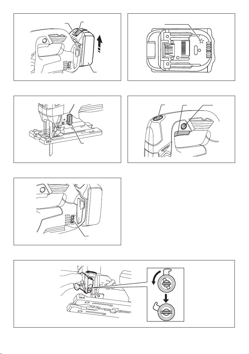
Installing or removing battery cartridge
(Fig. 1)
CAUTION:
• Always switch off the tool before installing or removing
of the battery cartridge.
• Hold the tool and the battery cartridge firmly when
installing or removing battery cartridge. Failure to
hold the tool and the battery cartridge firmly may cause
them to slip off your hands and result in damage to the
tool and battery cartridge and a personal injury.
To remove the battery cartridge, slide it from the tool while
sliding the button on the front of the cartridge.
To install the battery cartridge, align the tongue on the
battery cartridge with the groove in the housing and slip it
into place. Insert it all the way until it locks in place with a
little click. If you can see the red indicator on the upper
side of the button, it is not locked completely.
CAUTION:
• Always install the battery cartridge fully until the red
indicator cannot be seen. If not, it may accidentally fall
out of the tool, causing injury to you or someone
around you.
• Do not install the battery cartridge forcibly. If the
cartridge does not slide in easily, it is not being inserted
correctly.
Battery protection system (Lithium-ion
battery with star marking) (Fig. 2)
Lithium-ion batteries with a star marking are equipped
with a protection system. This system automatically cuts
off power to the tool to extend battery life.
The tool will automatically stop during operation if the tool
and/or battery are placed under one of the following
conditions:
• Overloaded:
The tool is operated in a manner that causes it to
draw an abnormally high current.
In this situation, release the switch trigger on the tool
and stop the application that caused the tool to
become overloaded. Then pull the switch trigger
again to restart.
If the tool does not start, the battery is overheated. In
this situation, let the battery cool before pulling the
switch trigger again.
• Low battery voltage:
The remaining battery capacity is too low and the tool
will not operate. In this situation, remove and
recharge the battery.
7
Page 8
Selecting the cutting action (Fig. 3)
This tool can be operated with an orbital or a straight line
(up and down) cutting action. The orbital cutting action
thrusts the blade forward on the cutting stroke and greatly
increases cutting speed.
To change the cutting action, just turn the cutting action
changing lever to the desired cutting action position. Refer
to the table to select the appropriate cutting action.
Position Cutting action Applications
For cutting mild steel,
stainless steel and plastics.
For clean cuts in wood and
plywood.
For cutting mild steel,
aluminum and hard wood.
For cutting wood and
plywood.
For fast cutting in aluminum
and mild steel.
For fast cutting in wood and
plywood.
006376
0
Straight line
cutting action
Small orbit
cutting action
Medium orbit
cutting action
Large orbit
cutting action
Switch action
CAUTION:
• Before inserting the battery cartridge into the tool,
always check to see that the switch trigger actuates
properly and returns to the “OFF” position when
released. (Fig. 4)
To start the tool:
Press the lock switch to turn the tool into standby mode. It
turns the lamp on, too.
Pull the switch trigger to start the tool. Release the switch
trigger to stop.
For continuous operation, pull the switch trigger and then
push in the lock on button.
To stop the tool from the locked position, pull the switch
trigger fully, and then release it.
In standby mode, press the lock switch to turn the lamp off
and turn the tool into lock-off mode.
NOTE:
• The lock switch does not actuate during cutting
operation.
• When the tool is in standby mode, the lamp keeps
lighting.
• If the tool is left 10 seconds without any operations in
standby mode, the tool is automatically turned into
lock-off mode and the lamp goes off.
Lighting up the lamps
CAUTION:
• Do not look in the lamp or see the source of lamp
directly.
To turn on the lamp, press the lock switch.
To turn off the lamp within 10 seconds, press the lock
switch again.
NOTE:
• Use a dry cloth to wipe the dirt off the lens of lamp. Be
careful not to scratch the lens of lamp, or it may lower
the illumination.
• When the tool is overheated, the lamp flickers. Cool
down the tool fully before operating again.
Speed adjusting dial (Fig. 5)
The tool speed can be infinitely adjusted by turning the
speed adjusting dial. You can get the highest speed at 6
and the lowest speed at 1.
Refer to the table to select the proper speed for the
workpiece to be cut. However, the appropriate speed may
differ with the type or thickness of the workpiece. In
general, higher speeds will allow you to cut workpieces
faster but the service life of the blade will be reduced.
Workpiece to be cut Number on adjusting dial
Wood 4 - 6
Mild steel 3 - 6
Stainless steel 3 - 4
Aluminum 3 - 6
Plastics 1 - 4
013925
CAUTION:
• The speed adjusting dial can be turned only as far as 6
and back to 1. Do not force it past 6 or 1, or the speed
adjusting function may no longer work.
NOTE:
• When the speed adjusting dial is at 3 or higher, the tool
automatically reduces the no-load speed to reduce the
vibration under no-load. Once the tool gets load, the
tool speed reaches the preset speed. Then the tool
keeps the speed until the tool is switched off.
ASSEMBLY
CAUTION:
• Always be sure that the tool is switched off and the
battery cartridge is removed before carrying out any
work on the tool.
Installing or removing saw blade
CAUTION:
• Always clean out all chips or foreign matter adhering to
the blade and/or blade holder. Failure to do so may
cause insufficient tightening of the blade, resulting in a
serious personal injury.
• Do not touch the blade or the workpiece immediately
after operation; they may be extremely hot and could
burn your skin.
• Tighten the saw blade securely. Failure to do so may
cause a serious injury.
• When you remove the saw blade, be careful not to hurt
your fingers with the top of the blade or the tips of
workpiece. (Fig. 6)
Before installing the blade, make sure that the blade
holder is in the released position.
To install the blade, insert the blade (teeth facing forward)
into the blade holder until it latches. The blade holder
moves to the fixed position by itself and the blade is
locked. Pull the blade lightly to make sure that the blade
does not fall off during operation.
8
Page 9

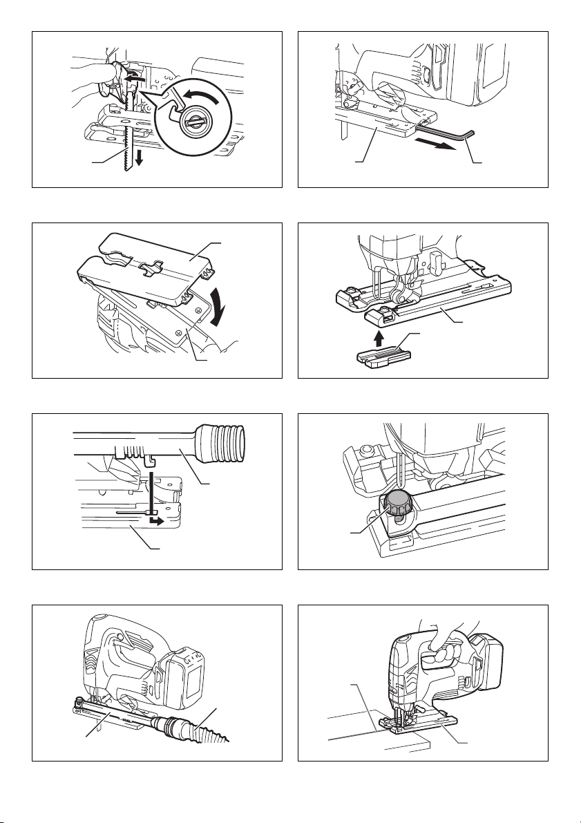
CAUTION:
• Do not open the tool opener excessively, or it may
cause tool damage. (Fig. 7)
To remove the blade, push the tool opener forward as far
as it will go. This allows the blade to be released.
NOTE:
• Occasionally lubricate the roller.
Hex wrench storage (Fig. 8)
When not in use, store the hex wrench as shown in the
figure to keep it from being lost.
Cover plate (Fig. 9)
Use the cover plate when cutting decorative veneers,
plastics, etc. It protects sensitive or delicate surfaces from
damage. Fit it on the back of the tool base.
Anti-splintering device (Fig. 10)
For splinter-free cuts, the anti-splintering device can be
used. To install the anti-splintering device, move the tool
base all the way forward and fit it from the back of tool
base. When you use the cover plate, install the antisplintering device onto the cover plate.
CAUTION:
• The anti-splintering device cannot be used when
making bevel cuts.
Dust extraction
The dust nozzle (optional accessory) is recommended to
perform clean cutting operations. (Fig. 11)
To attach the dust nozzle on the tool, insert the hook of
dust nozzle into the hole in the base. (Fig. 12)
To secure the dust nozzle, tighten the clamp screw at the
front of the dust nozzle.
The dust nozzle can be installed on either left or right side
of the base. (Fig. 13)
Then connect a Makita vacuum cleaner to the dust
nozzle.
OPERATION
CAUTION:
• Always hold the base flush with the workpiece. Failure
to do so may cause blade breakage, resulting in a
serious injury.
NOTE:
• If the tool is operated continuously until the battery
cartridge has discharged, allow the tool to rest for
15 minutes before proceeding with a fresh battery.
(Fig. 14)
Turn the tool on without the blade making any contact and
wait until the blade attains full speed. Then rest the base
flat on the workpiece and gently move the tool forward
along the previously marked cutting line.
When cutting curves, advance the tool very slowly.
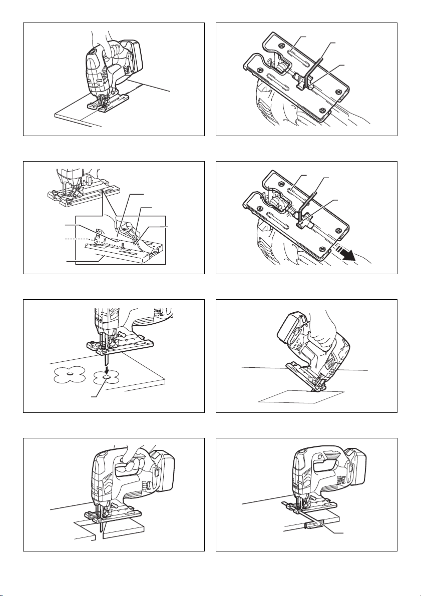
Bevel cutting (Fig. 15)
CAUTION:
• Always be sure that the tool is switched off and the
battery cartridge is removed before tilting the base.
With the base tilted, you can make bevel cuts at any angle
between 0° and 45° (left or right). (Fig. 16)
To tilt the base, loosen the bolt on the back of the base
with the hex wrench. Move the base so that the bolt is
positioned in the center of the bevel slot in the base.
(Fig. 17)
Tilt the base until the desired bevel angle is obtained. The
V-notch of the gear housing indicates the bevel angle by
graduations. Then tighten the bolt firmly to secure the
base.
Front flush cuts (Fig. 18)
Loosen the bolt on the back of the base with the hex
wrench and slide the base all the way back. Then tighten
the bolt to secure the base.
Cutouts
Cutouts can be made with either of two methods A or B.
A) Boring a starting hole: (Fig. 19)
• For internal cutouts without a lead-in cut from an edge,
pre-drill a starting hole 12 mm or more in diameter.
Insert the blade into this hole to start your cut.
B) Plunge cutting: (Fig. 20)
• You need not bore a starting hole or make a lead-in cut
if you carefully do as follows.
1. Tilt the tool up on the front edge of the base with the
blade point positioned just above the workpiece
surface.
2. Apply pressure to the tool so that the front edge of the
base will not move when you switch on the tool and
gently lower the back end of the tool slowly.
3. As the blade pierces the workpiece, slowly lower the
base of the tool down onto the workpiece surface.
4. Complete the cut in the normal manner.
Finishing edges (Fig. 21)
To trim edges or make dimensional adjustments, run the
blade lightly along the cut edges.
Metal cutting
Always use a suitable coolant (cutting oil) when cutting
metal. Failure to do so will cause significant blade wear.
The underside of the workpiece can be greased instead of
using a coolant.
Rip fence set (optional accessory)
CAUTION:
• Always be sure that the tool is switched off and the
battery cartridge is removed before installing or
removing accessories.
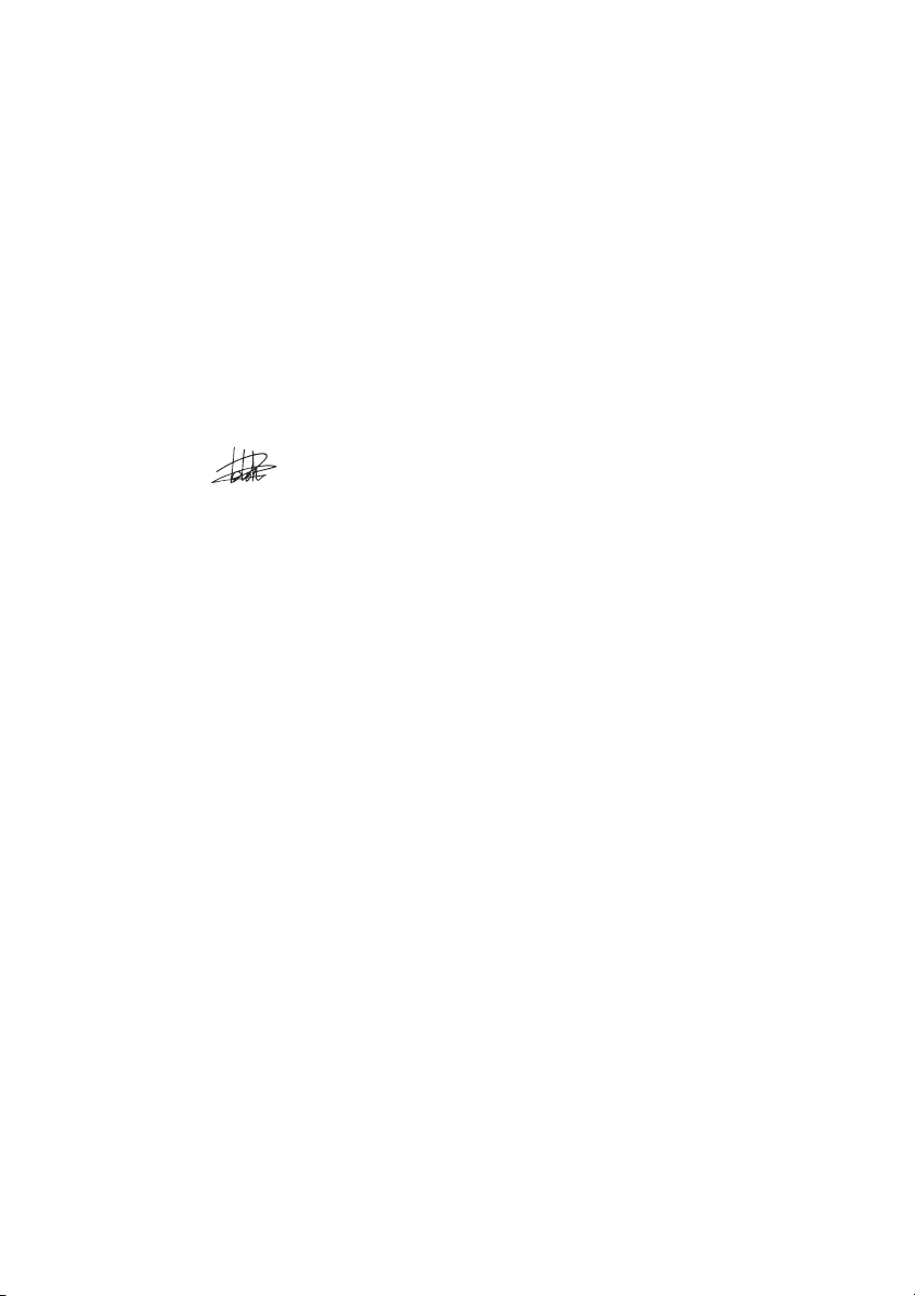
1. Straight cuts (Fig. 22)
When repeatedly cutting widths of 160 mm or less, use of
the rip fence will assure fast, clean, straight cuts. (Fig. 23)
To install, insert the rip fence into the rectangular hole on
the side of the tool base with the fence guide facing down.
Slide the rip fence to the desired cutting width position,
then tighten the bolt to secure it.
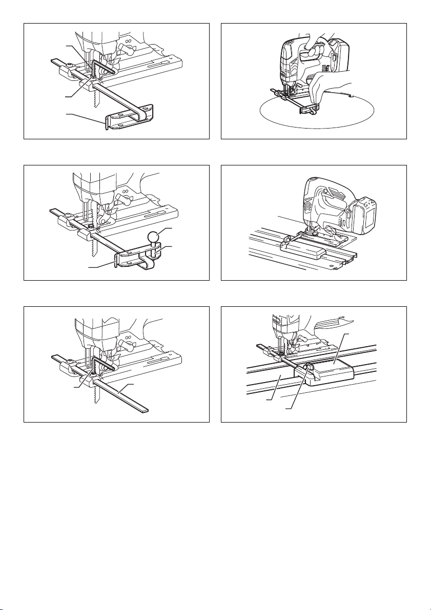
2. Circular cuts (Fig. 24 & 25)
When cutting circles or arcs of 170 mm or less in radius,
install the rip fence as follows.
9
Page 10

1. Insert the rip fence into the rectangular hole on the
side of the base with the fence guide facing up. Insert
the circular guide pin through either of the two holes
on the fence guide. Screw the threaded knob onto the
pin to secure the pin.
2. Now slide the rip fence to the desired cutting radius,
and tighten the bolt to secure it in place. Then move
the base all the way forward.
NOTE:
• Always use blades No. B-17, B-18, B-26 or B-27 when
cutting circles or arcs.
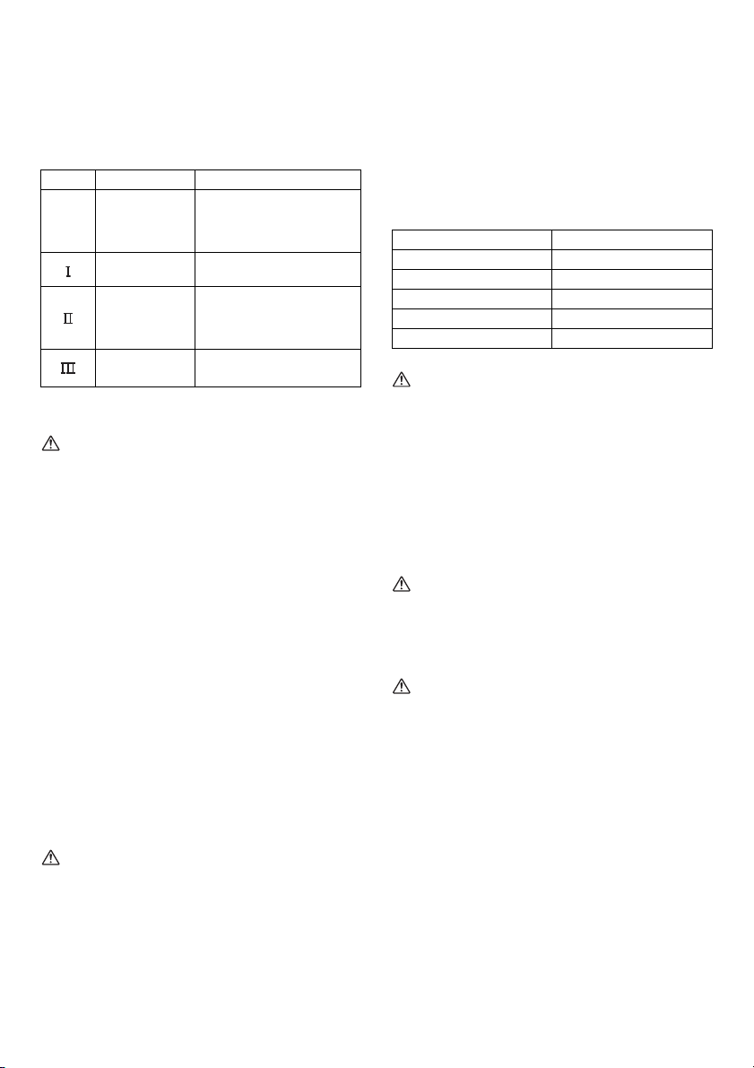
Guide rail adapter set (optional
accessory) (Fig. 26)
When cutting parallel and uniform width or cutting straight,
the use of the guide rail and the guide rail adapter will
assure the production of fast and clean cuts.
To install the guide rail adapter, insert the rule bar into the
square hole of the base as far as it goes. Secure the bolt
with the hex wrench securely. (Fig. 27)
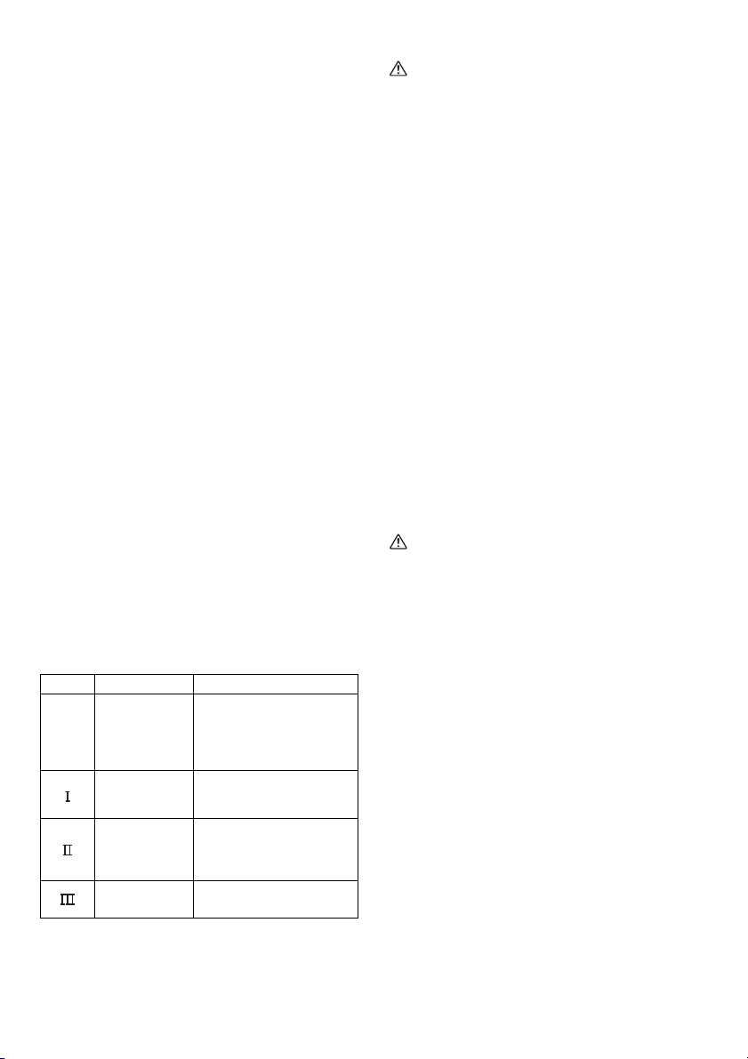
Install the guide rail adapter on the rail of the guide rail.
Insert the rule bar into the square hole of the guide rail
adapter. Put the base to the side of the guide rail, and
secure the bolt securely. (Fig. 28)
CAUTION:
• Always use blades No. B-8, B-13, B-16, B-17 or 58
when using the guide rail and the guide rail adapter.
MAINTENANCE
CAUTION:
• Always be sure that the tool is switched off and the
battery cartridge is removed before attempting to
perform inspection or maintenance.
• Never use gasoline, benzine, thinner, alcohol or the
like. Discoloration, deformation or cracks may result.
To maintain product SAFETY and RELIABILITY, repairs,
any other maintenance or adjustment should be
performed by Makita Authorized Service Centers, always
using Makita replacement parts.
OPTIONAL ACCESSORIES
CAUTION:
• These accessories or attachments are recommended
for use with your Makita tool specified in this manual.
The use of any other accessories or attachments might
present a risk of injury to persons. Only use accessory
or attachment for its stated purpose.
If you need any assistance for more details regarding
these accessories, ask your local Makita Service Center.
• Jig saw blades
•Hex wrench 4
• Rip fence (guide rule) set
• Guide rail adapter set
• Guide rail set
• Anti-splintering device
• Cover plate
• Dust nozzle assy
• Makita genuine battery and charger
NOTE:
• Some items in the list may be included in the tool
package as standard accessories. They may differ
from country to country.
Noise
ENG905-1
The typical A-weighted noise level determined according
to EN60745:
Model DJV142
Sound pressure level (L
Uncertainty (K): 3 dB (A)
): 78 dB (A)
pA
The noise level under working may exceed 80 dB (A).
Model DJV182
Sound pressure level (L
Uncertainty (K): 3 dB (A)
): 77 dB (A)
pA
The noise level under working may exceed 80 dB (A).
Wear ear protection.
Vibration
ENG900-1
The vibration total value (tri-axial vector sum) determined
according to EN60745:
Model DJV142
Work mode: cutting boards
Vibration emission (a
Uncertainty (K): 1.5 m/s
h,B
Work mode: cutting sheet metal
Vibration emission (a
Uncertainty (K): 1.5 m/s
h,M
): 7.0 m/s
2
): 4.0 m/s
2
2
2
Model DJV182
Work mode: cutting boards
Vibration emission (a
Uncertainty (K): 1.5 m/s
h,B
Work mode: cutting sheet metal
Vibration emission (a
Uncertainty (K): 1.5 m/s
h,M
): 7.0 m/s
2
): 3.5 m/s
2
2
2
ENG901-1
• The declared vibration emission value has been
measured in accordance with the standard test method
and may be used for comparing one tool with another.
• The declared vibration emission value may also be
used in a preliminary assessment of exposure.
WARNING:
• The vibration emission during actual use of the power
tool can differ from the declared emission value
depending on the ways in which the tool is used.
• Be sure to identify safety measures to protect the
operator that are based on an estimation of exposure in
the actual conditions of use (taking account of all parts
of the operating cycle such as the times when the tool
is switched off and when it is running idle in addition to
the trigger time).
10
Page 11
For European countries only
ENH101-16
EC Declaration of Conformity
We Makita Corporation as the responsible
manufacturer declare that the following Makita
machine(s):
Designation of Machine:
Cordless Jig Saw
Model No./Type: DJV142, DJV182
are of series production and
Conforms to the following European Directives:
2006/42/EC
And are manufactured in accordance with the following
standards or standardised documents:
EN60745
The technical documentation is kept by:
Makita International Europe Ltd.
Technical Department,
Michigan Drive, Tongwell,
Milton Keynes, Bucks MK15 8JD, England
5. 3. 2013
Tomoyasu Kato
Director
Makita Corporation
3-11-8, Sumiyoshi-cho,
Anjo, Aichi, 446-8502, JAPAN
11
Page 12

NEDERLANDS (Originele instructies)
Verklaring van het onderdelenoverzicht
1. Rode deel
2. Knop
3. Accu
4. Ster-merkteken
5. Zaagmethode-keuzehendel
6. Vergrendelknop
7. Aan/uit-schakelaar
8. Vastzetknop
9. Snelheidsregelaar
10. Vergrendelde stand
11. Ontgrendelde stand
12. Decoupeerzaagblad
13. Zool
14. Inbussleutel
15. Dekplaat
16. Antisplinterhulpstuk
17. Stofafzuigaansluitmond
18. Klemschroef
19. Slang naar stofzuiger
20. Zaaglijn
21. Bout
22. Verstekgleuf
23. Schaalverdeling
24. V-naad
25. Tandwielhuis
26. Begingat
27. Breedtegeleider
28. Geleider
29. Knop met schroefdraad
30. Cirkelgeleidepen
31. Liniaal
32. Geleiderailadapter
33. Schroef
34. Geleiderail
TECHNISCHE GEGEVENS
Model DJV142 DJV182
Slaglengte 26 mm 26 mm
Hout 135 mm 135 mm
Max. zaagdikte
Aantal snijbewegingen per minuut (min
Totale lengte 264 mm 266 mm
Nettogewicht 2,5 kg 2,6 kg
Nominale spanning 14,4 volt gelijkstroom 18 volt gelijkstroom
• Als gevolg van ons doorlopende onderzoeks- en ontwikkelingsprogramma, zijn de technische gegevens van dit
gereedschap onderhevig aan veranderingen zonder voorafgaande kennisgeving.
• Specificaties en accu’s kunnen van land tot land verschillen.
• Gewicht, inclusief de accu, volgens de EPTA-procedure 01/2003
Gebruiksdoeleinden
Dit gereedschap is bedoeld voor het zagen van hout,
kunststof en metaal. Door het uitgebreide assortiment
accessoires en zaagbladen, kan het gereedschap worden
gebruikt voor vele doeleinden en is het zeer geschikt voor
gebogen of cirkelvormige zaagsneden.
Algemene
veiligheidswaarschuwingen voor
elektrisch gereedschap GEA010-1
WAARSCHUWING Lees alle
veiligheidswaarschuwingen en alle instructies. Het
niet volgen van de waarschuwingen en instructies kan
leiden tot elektrische schokken, brand en/of ernstig letsel.
Bewaar alle waarschuwingen en
instructies om in de toekomst te
kunnen raadplegen.
VEILIGHEIDSWAARSCHUWINGEN
SPECIFIEK VOOR EEN
ACCUDECOUPEERZAAG GEB045-2
1. Houd het elektrisch gereedschap vast aan het
geïsoleerde oppervlak van de handgrepen
wanneer u werkt op plaatsen waar het accessoire
Zacht staal 10 mm 10 mm
Aluminium 20 mm 20 mm
-1
) 800 - 3.500 800 - 3.500
ENE019-1
met verborgen bedrading in aanraking kan komen.
Wanneer het accessoire in aanraking komen met
onder spanning staande draden, zullen de nietgeïsoleerde metalen delen van het gereedschap
onder spanning komen te staan zodat de gebruiker
een elektrische schok kan krijgen.
2. Gebruik klemmen of een andere praktische
methode om het werkstuk op een stabiele
ondergrond te bevestigen en ondersteunen. Als u
het werkstuk in uw hand of tegen uw lichaam geklemd
houdt, is het onvoldoende stabiel en kunt u de
controle erover verliezen.
3. Gebruik altijd een beschermende bril of een
veiligheidsbril. Een gewone bril of een zonnebril is
GEEN veiligheidsbril.
4. Voorkom dat u in spijkers zaagt. Inspecteer het
werkstuk op spijkers en verwijder deze alvorens
erin te zagen.
5. Zaag geen te grote werkstukken.
6. Controleer op voldoende vrije speling rondom het
werkstuk alvorens te zagen, zodat het blad de
vloer, werkbank, enz., niet raakt.
7. Houd het gereedschap stevig vast.
8. Zorg ervoor dat het blad het werkstuk niet raakt
voordat u het gereedschap hebt ingeschakeld.
9. Houd uw handen uit de buurt van bewegende
delen.
31
Page 13

10. Laat het gereedschap niet ingeschakeld liggen.
Bedien het gereedschap alleen wanneer u het
vasthoudt.
11. Schakel het gereedschap uit en wacht altijd tot het
blad volledig tot stilstand is gekomen voordat u
het blad uit het werkstuk verwijdert.
12. Raak het zaagblad en het werkstuk niet
onmiddellijk na gebruik aan. Zij kunnen bijzonder
heet zijn en brandwonden op uw huid
veroorzaken.
13. Laat het gereedschap niet onnodig onbelast
draaien.
14. Sommige materialen bevatten chemische stoffen
die giftig kunnen zijn. Neem
voorzorgsmaatregelen tegen het inademen van
stof en contact met de huid. Volg de
veiligheidsinstructies van de leverancier van het
materiaal op.
15. Gebruik altijd het juiste stofmasker/
ademhalingsapparaat voor het materiaal en de
toepassing waarmee u werkt.
BEWAAR DEZE INSTRUCTIES.
WAARSCHUWING:
Laat u NIET misleiden door een vals gevoel van
comfort en bekendheid met het gereedschap (na
veelvuldig gebruik) en neem alle
veiligheidsvoorschriften van het betreffende product
altijd strikt in acht. VERKEERD GEBRUIK of het niet
volgen van de veiligheidsinstructies in deze
gebruiksaanwijzing kan leiden tot ernstig persoonlijk
letsel.
BELANGRIJKE
VEILIGHEIDSINSTRUCTIES
ENC007-8
VOOR ACCU’S
1. Alvorens de accu in gebruik te nemen, leest u
eerst alle instructies en
waarschuwingsopschriften op (1) de acculader, (2)
de accu en (3) het apparaat waarin de accu wordt
aangebracht.
2. Haal de accu niet uit elkaar.
3. Als de gebruikstijd aanzienlijk korter is geworden,
stopt u onmiddellijk met het gebruik. Anders kan
dit leiden tot kans op oververhitting, mogelijke
brandwonden en zelfs een explosie.
4. Als de elektrolyt in uw ogen komt, wast u deze uit
met schoon water en raadpleegt u onmiddellijk
een arts. Dit kan leiden tot verlies van
gezichtsvermogen.
5. Sluit de accu niet kort:
(1) Raak de accupolen niet aan met enig
geleidend materiaal.
(2) Bewaar de accu niet op een plaats waar deze
in aanraking kan komen met andere metalen
voorwerpen, zoals spijkers, munten, enz.
(3) Stel de accu niet bloot aan water of regen.
Kortsluiting van de accu kan leiden tot een hoge
stroomsterkte, oververhitting, mogelijke
brandwonden en zelfs een defect.
6. Bewaar het gereedschap en de accu niet op
plaatsen waar de temperatuur kan oplopen tot
50 °C of hoger.
7. Werp de accu niet in een vuur, zelfs niet als deze
al ernstig beschadigd of helemaal versleten is. De
accu kan in een vuur exploderen.
8. Wees voorzichtig dat u de accu niet laat vallen of
ergens tegenaan stoot.
9. Gebruik nooit een beschadigde accu.
10. Neem de plaatselijke regelgeving met betrekking
tot het weggooien van de accu in acht.
BEWAAR DEZE INSTRUCTIES.
Tips voor een lange levensduur van de
accu
1. Laad de accu op voordat deze volledig leeg is.
Wanneer u merkt dat het gereedschap minder
vermogen heeft, stopt u met het gebruik ervan en
laadt u eerst de accu op.
2. Laad nooit een volledig opgeladen accu op.
Te lang opladen verkort de levensduur van de
accu.
3. Laad de accu op bij een omgevingstemperatuur
van 10 °C tot 40 °C. Laat een warme accu eerst
afkoelen voordat u deze oplaadt.
4. Laad de accu ieder half jaar op als u deze
gedurende een lange tijd niet gebruikt.
BESCHRIJVING VAN DE
FUNCTIES
LET OP:
• Zorg ervoor dat het gereedschap is uitgeschakeld en
dat de accu is verwijderd voordat u de werking van het
gereedschap aanpast of controleert.
De accu aanbrengen en verwijderen
(zie afb. 1)
LET OP:
• Schakel het gereedschap altijd uit voordat u de accu
aanbrengt of verwijdert.
• Houd het gereedschap en de accu stevig vast
tijdens het aanbrengen of verwijderen van de accu.
Als u het gereedschap en de accu niet stevig
vasthoudt, kunnen deze uit uw handen glippen en
beschadigd raken, of kan persoonlijk letsel worden
veroorzaakt.
Om de accu te verwijderen verschuift u de knop aan de
voorkant van de accu en schuift u tegelijkertijd de accu eraf.
Om de accu aan te brengen, lijnt u de lip op de accu uit
met de groef in de behuizing en duwt u de accu op zijn
plaats. Steek de accu zo ver mogelijk erin tot u een
klikgeluid hoort. Als u het rode deel aan de bovenkant van
de knop kunt zien, is de accu niet goed aangebracht.
LET OP:
• Breng de accu altijd helemaal aan totdat het rode deel
niet meer zichtbaar is. Als u dit niet doet, kan de accu
per ongeluk uit het gereedschap vallen en u of anderen
in uw omgeving verwonden.
32
Page 14
• Breng de accu niet met kracht aan. Als de accu niet
gemakkelijk erin kan worden geschoven, wordt deze
niet goed aangebracht.
Accubeveiligingssysteem (lithiumionaccu
met een ster-merkteken) (zie afb. 2)
Lithiumionaccu’s met een ster-merkteken zijn uitgerust
met een beveiligingssysteem. Dit systeem schakelt
automatisch de voeding naar het gereedschap uit om de
levensduur van de accu te verlengen.
Het gereedschap zal tijdens gebruik automatisch stoppen
wanneer het gereedschap en/of de accu zich in een van
de volgende omstandigheden bevinden:
• Overbelasting:
Het gereedschap wordt gebruikt op een manier die
ertoe leidt dat een abnormaal hoge stroomsterkte uit
de accu wordt getrokken.
Laat in die situatie de aan/uit-schakelaar van het
gereedschap los en stop het gebruik dat ertoe leidde
dat het gereedschap overbelast werd. Knijp daarna
opnieuw de aan/uit-schakelaar in om het
gereedschap weer in te schakelen.
Als het gereedschap niet wordt ingeschakeld, is de
accu oververhit. In die situatie laat u de accu eerst
afkoelen voordat u opnieuw de aan/uit-schakelaar
inknijpt.
• Lage accuspanning:
De resterende acculading is te laag en het
gereedschap wordt niet ingeschakeld. Verwijder in
die situatie de accu en laad hem op.
De zaagmethode kiezen (zie afb. 3)
Dit gereedschap kan worden ingesteld op een rechte (open neergaande) of pendelende zaagmethode. Bij de
pendelende zaagmethode wordt het zaagblad naar voren
geduwd tijdens de zaagslag waardoor de zaagsnelheid
sterk toeneemt.
Om de zaagmethode te veranderen, draait u de
zaagmethode-keuzehendel naar de gewenste
zaagmethodestand. Raadpleeg de tabel om de juiste
zaagmethode te kiezen.
Stand Zaagmethode Toepassingen
Voor het zagen van zacht
staal, roestvrij staal en
kunststoffen.
Voor schone zaagsneden in
hout en multiplex.
Voor het zagen van zacht
staal, aluminium en
hardhout.
Voor het zagen van hout en
multiplex.
For fast cutting in aluminum
and mild steel.
Voor het snel zagen van
hout en multiplex.
006376
0
Zagen langs
rechte lijn
Zagen in een
scherpe bocht
Zagen in een
normale bocht
Zagen in een
flauwe bocht
Werking van de aan/uit-schakelaar
LET OP:
• Controleer altijd, voordat u de accu in het gereedschap
steekt, of de aan/uit-schakelaar op de juiste manier
schakelt en weer terugkeert naar de uit-stand nadat
deze is losgelaten (zie afb. 4).
Om het gereedschap in te schakelen:
Druk op de vergrendelknop om het gereedschap op
standby te zetten. Hierdoor wordt tevens de lamp
ingeschakeld.
Knijp de aan/uit-schakelaar in om het gereedschap in te
schakelen. Laat de aan/uit-schakelaar los om het
gereedschap te stoppen.
Om het gereedschap continu te laten werken, knijpt u de
aan/uit-schakelaar in en drukt u vervolgens op de
vastzetknop.
Om vanuit de vergrendelde werking het gereedschap te
stoppen, knijpt u de aan/uit-schakelaar helemaal in en
laat u deze vervolgens weer los.
Druk tijdens standby op de vergrendelknop om de lamp
uit te schakelen en het gereedschap te vergrendelen.
OPMERKING:
• De vergrendelknop werkt niet tijdens het zagen.
• Terwijl het gereedschap standby staat, blijft de lamp
branden.
• Als het gereedschap gedurende 10 seconden op
standby blijft staan zonder bediend te worden, wordt
het gereedschap automatisch vergrendeld en gaat de
lamp uit.
De lamp inschakelen
LET OP:
• Kijk niet rechtstreeks in de lamp of naar de bron van de
lamp.
Druk op de vergrendelknop om de lamp in te schakelen.
Om de lamp binnen 10 seconden uit te schakelen, drukt u
nogmaals op de vergrendelknop.
OPMERKING:
• Gebruik een doek om het vuil van de lens van de lamp
te vegen. Wees voorzichtig de lens van de lamp niet te
bekrassen om de lichtopbrengst niet te verlagen.
• Als het gereedschap oververhit raakt, begint de lamp te
knipperen. Laat het gereedschap afkoelen voordat u
het weer bedient.
Snelheidsregelaar (zie afb. 5)
De snelheid van het gereedschap kan worden ingesteld
door de snelheidsregelaar te draaien. Op stand 6 is de
snelheid het hoogst en op stand 1 het laagst.
Zie de tabel om de juiste snelheid te kiezen voor het
werkstuk dat u wilt zagen. De juiste snelheid is echter ook
afhankelijk van de soort en de dikte van het werkstuk.
Over het algemeen kunt u op een hogere snelheid een
werkstuk sneller zagen, maar gaat de levensduur van het
zaagblad achteruit.
33
Page 15

Te zagen werkstuk Cijfer op snelheidsregelaar
Hout 4 - 6
Zacht staal 3 - 6
Roestvrij staal 3 - 4
Aluminium 3 - 6
Kunststof 1 - 4
013925
LET OP:
• U kunt de snelheidsregelaar alleen tot aan het cijfer 6
draaien en terug naar 1. Forceer de regelaar niet
voorbij de 6 of de 1 omdat de snelheidsregeling
daardoor defect kan raken.
OPMERKING:
• Als de snelheidsregelaar op 3 of hoger staat, verlaagt
het gereedschap automatisch het onbelaste toerental
om de trillingen in onbelaste toestand te verlagen.
Zodra het gereedschap weer belast wordt, wordt de
snelheid van het gereedschap verhoogd tot de
ingestelde snelheid. Vervolgens handhaaft het
gereedschap deze snelheid tot het wordt
uitgeschakeld.
ONDERDELEN AANBRENGEN EN
VERWIJDEREN
LET OP:
• Controleer altijd of het gereedschap is uitgeschakeld
en de accu is verwijderd alvorens enige
werkzaamheden aan het gereedschap te verrichten.
Het zaagblad aanbrengen en verwijderen
LET OP:
• Verwijder altijd eerst alle houtsnippers en vreemde
stoffen die aan het zaagblad en/of de zaagbladhouder
kleven. Als u dat niet doet is het mogelijk dat het
zaagblad onvoldoende wordt vastgeklemd, wat kan
leiden tot ernstig persoonlijk letsel.
• Raak het zaagblad en het werkstuk niet onmiddellijk na
gebruik aan. Zij kunnen bijzonder heet zijn en
brandwonden op uw huid veroorzaken.
• Zet het zaagblad stevig vast. Als u dat niet doet, kan
dat leiden tot ernstig persoonlijk letsel.
• Wees voorzichtig bij het verwijderen van het zaagblad
dat u uw vingers niet bezeert aan de punt van het
zaagblad of de uiteinden van het werkstuk (zie afb. 6).
Controleer voordat u het zaagblad probeert aan te
brengen of de zaagbladhouder in de ontgrendelde stand
staat.
Om het zaagblad aan te brengen, steekt u het zaagblad
(met de tanden naar voren gericht) in de zaagbladhouder
tot het wordt vergrendeld. De zaagbladhouder beweegt uit
zichzelf naar de vergrendelde stand en het zaagblad is
vergrendeld. Trek zacht aan het zaagblad om er zeker
van te zijn dat het zaagblad er niet uitvalt tijdens gebruik.
LET OP:
• Open de gereedschapsopener niet overmatig ver
omdat anders het gereedschap kan worden
beschadigd (zie afb. 7).
Om het zaagblad te verwijderen, duwt u de
gereedschapsopener zo ver mogelijk naar voren.
Hierdoor wordt het zaagblad ontgrendeld.
OPMERKING:
• Smeer af en toe de rol.
Opbergplaats van de inbussleutel
(zie afb. 8)
Wanneer u de inbussleutel niet gebruikt, bergt u deze op
de plaats aangegeven in de afbeelding op, om te
voorkomen dat deze wordt verloren.
Dekplaat (zie afb. 9)
Gebruik de dekplaat wanneer u zaagt in decoratieve
deklagen, kunststoffen, enz. Hij beschermt gevoelige en
delicate oppervlakken tegen beschadiging. Breng hem
aan op de onderkant van de zool.
Antisplinterhulpstuk (zie afb. 10)
Voor zagen zonder splinters kunt u het
antisplinterhulpstuk gebruiken. Om het
antisplinterhulpstuk te monteren, zet u de zool in de
voorste stand en brengt u het hulpstuk eerst aan op de
achterrand van de zool. Als u de dekplaat gebruikt, brengt
u het antisplinterhulpstuk aan op de dekplaat.
LET OP:
• Het antisplinterhulpstuk kan niet worden gebruikt bij
verstekzagen.
Stofafzuiging
De stofafzuigaansluitmond (los verkrijgbaar) wordt
aanbevolen om tijdens het zagen schoon te werken
(zie afb. 11).
Om de stofafzuigaansluitmond op het gereedschap aan te
brengen, steekt u de haak van de stofafzuigaansluitmond
in het gat in de zool (zie afb. 12).
Om de stofafzuigaansluitmond vast te zetten, draait u de
klemschroef voorop de stofafzuigaansluitmond aan.
De stofafzuigaansluitmond kan op de linker- of
rechterkant van de zool worden aangebracht.
(zie afb. 13).
Sluit vervolgens een Makita-stofzuiger aan op de
stofafzuigaansluitmond.
BEDIENING
LET OP:
• Houd de zool altijd vlak met het oppervlak van het
werkstuk. Als u dat niet doet bestaat de kans dat het
zaagblad breekt, wat kan leiden tot ernstig persoonlijk
letsel.
OPMERKING:
• Als het gereedschap continu wordt bediend totdat de
accu leeg is, laat u het gereedschap gedurende
15 minuten liggen alvorens verder te werken met een
volle accu (zie afb. 14).
Schakel het gereedschap in zonder dat het zaagblad iets
raakt en wacht tot het zaagblad op volle snelheid is.
Plaats daarna de zool vlak op het werkstuk en beweeg
het gereedschap rustig naar voren langs een eerder
aangebrachte zaaglijn.
34
Page 16

Als u in een bocht zaagt, beweegt u het gereedschap zeer
langzaam vooruit.
Verstekzagen (zie afb. 15)
LET OP:
• Zorg er altijd voor dat het gereedschap is
uitgeschakeld en de accu is verwijderd, voordat u de
zool kantelt.
Met een gekantelde zool kunt u verstekzagen onder elke
hoek tussen 0° en 45° (links of rechts) (zie afb. 16).
Om de zool te kantelen draait u de bout op de onderkant
van de zool los met behulp van de inbussleutel. Verplaats
de zool zodat de bout zich in het midden van de
verstekgleuf in de zool bevindt (zie afb. 17).
Kantel de zool tot de gewenste verstekhoek is bereikt. De
V-naad van het tandwielhuis geeft de verstekhoek aan op
een schaalverdeling. Draai daarna de bout stevig vast om
de zool vast te zetten.
Zaagsneden tot aan de voorrand
(zie afb. 18)
Draai met de inbussleutel de bout op de onderkant van de
zool los en schuif de zool helemaal naar achteren. Draai
daarna de bout vast om de zool vast te zetten.
Uitsnijdingen
U kunt uitsnijdingen maken volgens methode A of B.
A) Een begingat boren: (zie afb. 19)
• Voor uitsnijdingen midden in een werkstuk zonder in te
zagen vanaf de rand, boort u vooraf een gat met een
diameter van 12 mm of meer. Steek het zaagblad in dit
gat voordat u begint te zagen.
B) Blinde zaagsnede: (zie afb. 20)
• U hoeft geen begingat te boren of vanaf de rand in te
zagen als u voorzichtig als volgt te werk gaat.
1. Kantel het gereedschap op de voorrand van de zool
met de punt van het zaagblad vlak boven het
oppervlak van het werkstuk.
2. Oefen druk uit op het gereedschap zodat de voorrand
van de zool niet beweegt wanneer u het gereedschap
inschakelt, en laat de achterkant van het gereedschap
voorzichtig zakken.
3. Naarmate het zaagblad het werkstuk doorboort, laat u
de zool van het gereedschap langzaam zakken tot op
het oppervlak van het werkstuk.
4. Maak de zaagsnede op de normale manier.
Randen afwerken (zie afb. 21)
Om randen af te werken of afmetingen iets bij te zagen,
beweegt u het zaagblad licht langs de reeds gezaagde
randen van het werkstuk.
Zagen van metaal
Gebruik tijdens het zagen van metaal altijd een geschikte
koelvloeistof (zaagolie). Als u dat niet doet, zal het
zaagblad sterk slijten. De onderkant van het werkstuk kan
met vet worden ingesmeerd in plaats van een
koelvloeistof te gebruiken.
Breedtegeleider (los verkrijgbaar)
LET OP:
• Zorg er altijd voor dat het gereedschap is
uitgeschakeld en de accu is verwijderd, voordat u
accessoires aanbrengt of verwijdert.
1. Rechte zaagsneden (zie afb. 22)
Als u herhaaldelijk een breedte van minder dan 160 mm
moet afzagen, kunt u door de breedtegeleider te
gebruiken snel, schoon en recht zagen (zie afb. 23).
Om hem aan te brengen steekt u de breedtegeleider in de
rechthoekige opening in de zijkant van de zool met de
geleider omlaag gericht. Schuif de breedtegeleider naar
de gewenste zaagbreedte en draai daarna de bout vast
om hem vast te zetten.
2. Cirkelvormige zaagsneden (zie afb. 24 en 25)
Als u cirkels of bogen met een straal van 170 mm of
minder wilt zagen, brengt u de breedtegeleider als volgt
aan.
1. Steek de breedtegeleider in de rechthoekige opening
in de zijkant van de zool met de geleider omhoog
gericht. Steek de cirkelgeleidepen in een van de twee
gaten in de geleider. Draai de knop met schroefdraad
op de pen om deze vast te zetten.
2. Schuif vervolgens de breedtegeleider naar de
gewenste zaagstraal en draai de bout vast om hem
vast te zetten. Beweeg tenslotte de zool helemaal
naar voren.
OPMERKING:
• Gebruik altijd zaagbladen nr. B-17, B-18, B-26 of B-27
voor het zagen van cirkels of bogen.
Geleiderailadapter (los verkrijgbaar) (zie
afb. 26)
Als u een parallelle en uniforme breedte of recht wilt
zagen, kunt u door de geleiderail en geleiderailadapter te
gebruiken snelle en schone zaagsneden produceren.
Om de geleiderailadapter aan te brengen, steekt u de
liniaal zo ver mogelijk in de rechthoekige opening in de
zijkant van de zool. Draai de bout stevig vast met de
inbussleutel (zie afb. 27).
Monteer de geleiderailadapter op de rail van de
geleiderail. Steek de liniaal in de rechthoekige opening in
de geleiderailadapter. Plaats de zool langs de zijkant van
de geleiderail en draai de bout stevig vast (zie afb. 28).
LET OP:
• Gebruik altijd zaagbladen nr. B-8, B-13, B-16, B-17 of
58 wanneer u de geleiderail en de geleiderailadapter
gebruikt.
ONDERHOUD
LET OP:
• Zorg er altijd voor dat de machine is uitgeschakeld en
de accu is verwijderd, voordat u een inspectie of
onderhoud uitvoert.
• Gebruik nooit benzine, wasbenzine, thinner, alcohol,
enz. Dit kan leiden tot verkleuren, vervormen of
barsten.
Om de VEILIGHEID en BETROUWBAARHEID van het
gereedschap te handhaven, dienen alle reparaties,
onderhoud en afstellingen te worden uitgevoerd door een
35
Page 17

erkend Makita-servicecentrum, en altijd met
gebruikmaking van originele Makitavervangingsonderdelen.
VERKRIJGBARE ACCESSOIRES
LET OP:
• Deze accessoires of hulpstukken worden aanbevolen
voor gebruik met het Makita-gereedschap dat in deze
gebruiksaanwijzing wordt beschreven. Het gebruik van
andere accessoires of hulpstukken kan gevaar voor
persoonlijk letsel opleveren. Gebruik de accessoires of
hulpstukken uitsluitend voor de aangegeven
gebruiksdoeleinden.
Mocht u meer informatie willen hebben over deze
accessoires, dan kunt u contact opnemen met uw
plaatselijke Makita-servicecentrum.
• Decoupeerzaagbladen
• Inbussleutel 4
• Breedtegeleider (liniaal), set
• Geleiderailadapter, set
• Geleiderail, set
• Antisplinterhulpstuk
• Dekplaat
• Stofafzuigaansluitmond, compleet
• Originele Makita-accu en -lader
OPMERKING:
• Sommige items op de lijst kunnen zijn inbegrepen in de
doos van het gereedschap als standaard toebehoren.
Zij kunnen van land tot land verschillen.
Geluid
De typische, A-gewogen geluidsniveaus zijn gemeten
volgens EN60745:
Model DJV142
Geluidsdrukniveau (L
Onzekerheid (K): 3 dB (A)
): 78 dB (A)
pA
Het geluidsniveau kan tijdens gebruik hoger worden dan
80 dB (A).
Model DJV182
Geluidsdrukniveau (L
Onzekerheid (K): 3 dB (A)
): 77 dB (A)
pA
Het geluidsniveau kan tijdens gebruik hoger worden dan
80 dB (A).
ENG905-1
Gebruikstoepassing: zagen van plaatstaal
Trillingsemissie (a
Onzekerheid (K): 1,5 m/s
h,M
): 3,5 m/s
2
2
ENG901-1
• De opgegeven trillingsemissiewaarde is gemeten
volgens de standaardtestmethode en kan worden
gebruikt om dit gereedschap te vergelijken met andere
gereedschappen.
• De opgegeven trillingsemissiewaarde kan ook worden
gebruikt voor een beoordeling vooraf van de
blootstelling.
WAARSCHUWING:
• De trillingsemissie tijdens het gebruik van het elektrisch
gereedschap in de praktijk kan verschillen van de
opgegeven trillingsemissiewaarde afhankelijk van de
manier waarop het gereedschap wordt gebruikt.
• Zorg ervoor dat veiligheidsmaatregelen worden
getroffen ter bescherming van de operator die zijn
gebaseerd op een schatting van de blootstelling onder
praktijkomstandigheden (rekening houdend met alle
fasen van de bedrijfscyclus, zoals de tijdsduur
gedurende welke het gereedschap is uitgeschakeld en
stationair draait, naast de ingeschakelde tijdsduur).
Alleen voor Europese landen
ENH101-16
EU-verklaring van conformiteit
Wij, Makita Corporation, als de verantwoordelijke
fabrikant, verklaren dat de volgende Makitamachine(s):
Aanduiding van de machine:
Accudecoupeerzaag
Modelnr./Type: DJV142, DJV182
in serie zijn geproduceerd en
Voldoen aan de volgende Europese richtlijnen:
2006/42/EC
En zijn gefabriceerd in overeenstemming met de
volgende normen of genormaliseerde documenten:
EN60745
De technische documentatie wordt bewaard door:
Makita International Europe Ltd.
Technical Department,
Michigan Drive, Tongwell,
Milton Keynes, Bucks MK15 8JD, Engeland
5. 3. 2013
Draag gehoorbescherming.
Trillingen
ENG900-1
De totale trillingswaarde (triaxiale vectorsom) zoals
vastgesteld volgens EN60745:
Model DJV142
Gebruikstoepassing: zagen van platen
Trillingsemissie (a
Onzekerheid (K): 1,5 m/s
h,B
Gebruikstoepassing: zagen van plaatstaal
Trillingsemissie (a
Onzekerheid (K): 1,5 m/s
h,M
): 7,0 m/s
2
): 4,0 m/s
2
2
2
Model DJV182
Gebruikstoepassing: zagen van platen
Trillingsemissie (a
Onzekerheid (K): 1,5 m/s
h,B
): 7,0 m/s
2
2
36
Tomoyasu Kato
Directeur
Makita Corporation
3-11-8, Sumiyoshi-cho,
Anjo, Aichi, 446-8502, JAPAN
 Loading...