

Page 1
INSTRUCTION MANUAL
MANUEL D'INSTRUCTION
MANUAL DE INSTRUCCIONES
Cordless Jig Saw
Scie sauteuse sans fil
Sierra Caladora Inalámbrica
DJV181
IMPORTANT: Read Before Using.
IMPORTANT: Lire avant usage.
IMPORTANTE: Leer antes de usar.
013927
1
Page 2

ENGLISH (Original instructions)
SPECIFICATIONS
Model DJV181
Length of stroke 26 mm (1")
Max. cutting capacities
Strokes per minute 800 - 3,500 /min
Overall length 298 mm (11-3/4")
Net weight 2.5 kg (5.5 lbs)
Rated voltage D.C. 18 V
Standard battery cartridge(s)
Warning: Use only the battery(ies) described.
• Due to our continuing program of research and development, the specifications herein are subject to change without notice.
• Specifications may differ from country to country.
• Weight according to EPTA-Procedure 01/2003
General Power Tool Safety
Warnings
WARNING Read all safety warnings and all
instructions. Failure to follow the warnings and
instructions may result in electric shock, fire and/or
serious injury.
Save all warnings and
instructions for future reference.
The term "power tool" in the warnings refers to your
mains-operated (corded) power tool or battery-operated
(cordless) power tool.
Work area safety
1. Keep work area clean and well lit. Cluttered or
dark areas invite accidents.
2. Do not operate power tools in explosive
atmospheres, such as in the presence of
flammable liquids, gases or dust. Power tools
create sparks which may ignite the dust or fumes.
3. Keep children and bystanders away while
operating a power tool. Distractions can cause
you to lose control.
Electrical Safety
4. Power tool plugs must match the outlet. Never
modify the plug in any way. Do not use any
adapter plugs with earthed (grounded) power
tools. Unmodified plugs and matching outlets will
reduce risk of electric shock.
5. Avoid body contact with earthed or grounded
surfaces such as pipes, radiators, ranges and
refrigerators. There is an increased risk of
electric shock if your body is earthed or grounded.
Wood 135 mm (5-5/16")
Mild steel 10 mm (3/8")
Aluminum 20 mm (25/32")
BL1830 / BL1840
GEA006-2
6. Do not expose power tools to rain or wet
conditions. Water entering a power tool will
increase the risk of electric shock.
7. Do not abuse the cord. Never use the cord for
carrying, pulling or unplugging the power tool.
Keep cord away from heat, oil, sharp edges or
moving parts. Damaged or entangled cords
increase the risk of electric shock.
8. When operating a power tool outdoors, use an
extension cord suitable for outdoor use. Use
of a cord suitable for outdoor use reduces the risk
of electric shock.
9. If operating a power tool in a damp location is
unavoidable, use a ground fault circuit
interrupter (GFCI) protected supply. Use of an
GFCI reduces the risk of electric shock.
Personal Safety
10. Stay alert, watch what you are doing and use
common sense when operating a power tool.
Do not use a power tool while you are tired or
under the influence of drugs, alcohol or
medication. A moment of inattention while
operating power tools may result in serious
personal injury.
11. Use personal protective equipment. Always
wear eye protection. Protective equipment such
as dust mask, non-skid safety shoes, hard hat, or
hearing protection used for appropriate conditions
will reduce personal injuries.
12. Prevent unintentional starting. Ensure the
switch is in the off-position before connecting
to power source and/or battery pack, picking
up or carrying the tool. Carrying power tools
with your finger on the switch or energising power
tools that have the switch on invites accidents.
2
Page 3

13. Remove any adjusting key or wrench before
turning the power tool on. A wrench or a key
left attached to a rotating part of the power tool
may result in personal injury.
14. Do not overreach. Keep proper footing and
balance at all times. This enables better control
of the power tool in unexpected situations.
15. Dress properly. Do not wear loose clothing or
jewellery. Keep your hair, clothing, and gloves
away from moving parts. Loose clothes,
jewellery or long hair can be caught in moving
parts.
16. If devices are provided for the connection of
dust extraction and collection facilities,
ensure these are connected and properly
used. Use of dust collection can reduce dust-
related hazards.
Power tool use and care
17. Do not force the power tool. Use the correct
power tool for your application. The correct
power tool will do the job better and safer at the
rate for which it was designed.
18. Do not use the power tool if the switch does
not turn it on and off. Any power tool that
cannot be controlled with the switch is dangerous
and must be repaired.
19. Disconnect the plug from the power source
and/or the battery pack from the power tool
before making any adjustments, changing
accessories, or storing power tools. Such
preventive safety measures reduce the risk of
starting the power tool accidentally.
20. Store idle power tools out of the reach of
children and do not allow persons unfamiliar
with the power tool or these instructions to
operate the power tool. Power tools are
dangerous in the hands of untrained users.
21. Maintain power tools. Check for misalignment
or binding of moving parts, breakage of parts
and any other condition that may affect the
power tool’s operation. If damaged, have the
power tool repaired before use. Many
accidents are caused by poorly maintained power
tools.
22. Keep cutting tools sharp and clean. Properly
maintained cutting tools with sharp cutting edges
are less likely to bind and are easier to control.
23. Use the power tool, accessories and tool bits
etc. in accordance with these instructions,
taking into account the working conditions
and the work to be performed. Use of the
power tool for operations different from those
intended could result in a hazardous situation.
Battery tool use and care
24. Recharge only with the charger specified by
the manufacturer. A charger that is suitable for
one type of battery pack may create a risk of fire
when used with another battery pack.
25. Use power tools only with specifically
designated battery packs. Use of any other
battery packs may create a risk of injury and fire.
26. When battery pack is not in use, keep it away
from other metal objects, like paper clips,
coins, keys, nails, screws or other small metal
objects, that can make a connection from one
terminal to another. Shorting the battery
terminals together may cause burns or a fire.
27. Under abusive conditions, liquid may be
ejected from the battery; avoid contact. If
contact accidentally occurs, flush with water.
If liquid contacts eyes, additionally seek
medical help. Liquid ejected from the battery
may cause irritation or burns.
Service
28. Have your power tool serviced by a qualified
repair person using only identical
replacement parts. This will ensure that the
safety of the power tool is maintained.
29. Follow instruction for lubricating and
changing accessories.
30. Keep handles dry, clean and free from oil and
grease.
GEB045-2
CORDLESS JIG SAW SAFETY
WARNINGS
1. Hold power tool by insulated gripping
surfaces, when performing an operation
where the cutting accessory may contact
hidden wiring. Cutting accessory contacting a
"live" wire may make exposed metal parts of the
power tool "live" and could give the operator an
electric shock.
2. Use clamps or another practical way to secure
and support the workpiece to a stable
platform. Holding the work by hand or against
your body leaves it unstable and may lead to loss
of control.
3. Always use safety glasses or goggles.
Ordinary eye or sun glasses are NOT safety
glasses.
4. Avoid cutting nails. Inspect workpiece for any
nails and remove them before operation.
5. Do not cut oversize workpiece.
6. Check for the proper clearance beyond the
workpiece before cutting so that the blade will
not strike the floor, workbench, etc.
3
Page 4

7. Hold the tool firmly.
8. Make sure the blade is not contacting the
workpiece before the switch is turned on.
9. Keep hands away from moving parts.
10. Do not leave the tool running. Operate the tool
only when hand-held.
11. Always switch off and wait for the blade to
come to a complete stop before removing the
blade from the workpiece.
12. Do not touch the blade or the workpiece
immediately after operation; they may be
extremely hot and could burn your skin.
13. Do not operate the tool at no-load
unnecessarily.
14. Some material contains chemicals which may
be toxic. Take caution to prevent dust
inhalation and skin contact. Follow material
supplier safety data.
15. Always use the correct dust mask/respirator
for the material and application you are
working with.
SAVE THESE INSTRUCTIONS.
WARNING:
DO NOT let comfort or familiarity with product
(gained from repeated use) replace strict adherence
to safety rules for the subject product. MISUSE or
failure to follow the safety rules stated in this
instruction manual may cause serious personal
injury.
USD301-1
Symbols
The followings show the symbols used for tool.
・ volts
・ direct current
・ no load speed
・ revolutions or reciprocation per minute
ENC007-8
IMPORTANT SAFETY
INSTRUCTIONS
FOR BATTERY CARTRIDGE
1. Before using battery cartridge, read all
instructions and cautionary markings on (1)
battery charger, (2) battery, and (3) product
using battery.
2. Do not disassemble battery cartridge.
3. If operating time has become excessively
shorter, stop operating immediately. It may
result in a risk of overheating, possible burns
and even an explosion.
4. If electrolyte gets into your eyes, rinse them
out with clear water and seek medical
attention right away. It may result in loss of
your eyesight.
5. Do not short the battery cartridge:
(1) Do not touch the terminals with any
conductive material.
(2) Avoid storing battery cartridge in a
container with other metal objects such
as nails, coins, etc.
(3) Do not expose battery cartridge to water
or rain.
A battery short can cause a large current flow,
overheating, possible burns and even a
breakdown.
6. Do not store the tool and battery cartridge in
locations where the temperature may reach or
exceed 50 ゚ C (122 ゚ F).
7. Do not incinerate the battery cartridge even if
it is severely damaged or is completely worn
out. The battery cartridge can explode in a fire.
8. Be careful not to drop or strike battery.
9. Do not use a damaged battery.
10. Follow your local regulations relating to
disposal of battery.
SAVE THESE INSTRUCTIONS.
Tips for maintaining maximum battery life
1. Charge the battery cartridge before
completely discharged.
Always stop tool operation and charge the
battery cartridge when you notice less tool
power.
2. Never recharge a fully charged battery
cartridge.
Overcharging shortens the battery service life.
3. Charge the battery cartridge with room
temperature at 10 ゚ C - 40 ゚ C (50 ゚ F - 104 ゚ F).
Let a hot battery cartridge cool down before
charging it.
4. Charge the battery cartridge once in every six
months if you do not use it for a long period
of time.
4
Page 5
FUNCTIONAL DESCRIPTION
CAUTION:
• Always be sure that the tool is switched off and the
battery cartridge is removed before adjusting or
checking function on the tool.
Installing or removing battery cartridge
1
2
3
013928
CAUTION:
• Always switch off the tool before installing or
removing of the battery cartridge.
• Hold the tool and the battery cartridge firmly
when installing or removing battery cartridge.
Failure to hold the tool and the battery cartridge
firmly may cause them to slip off your hands and
result in damage to the tool and battery cartridge
and a personal injury.
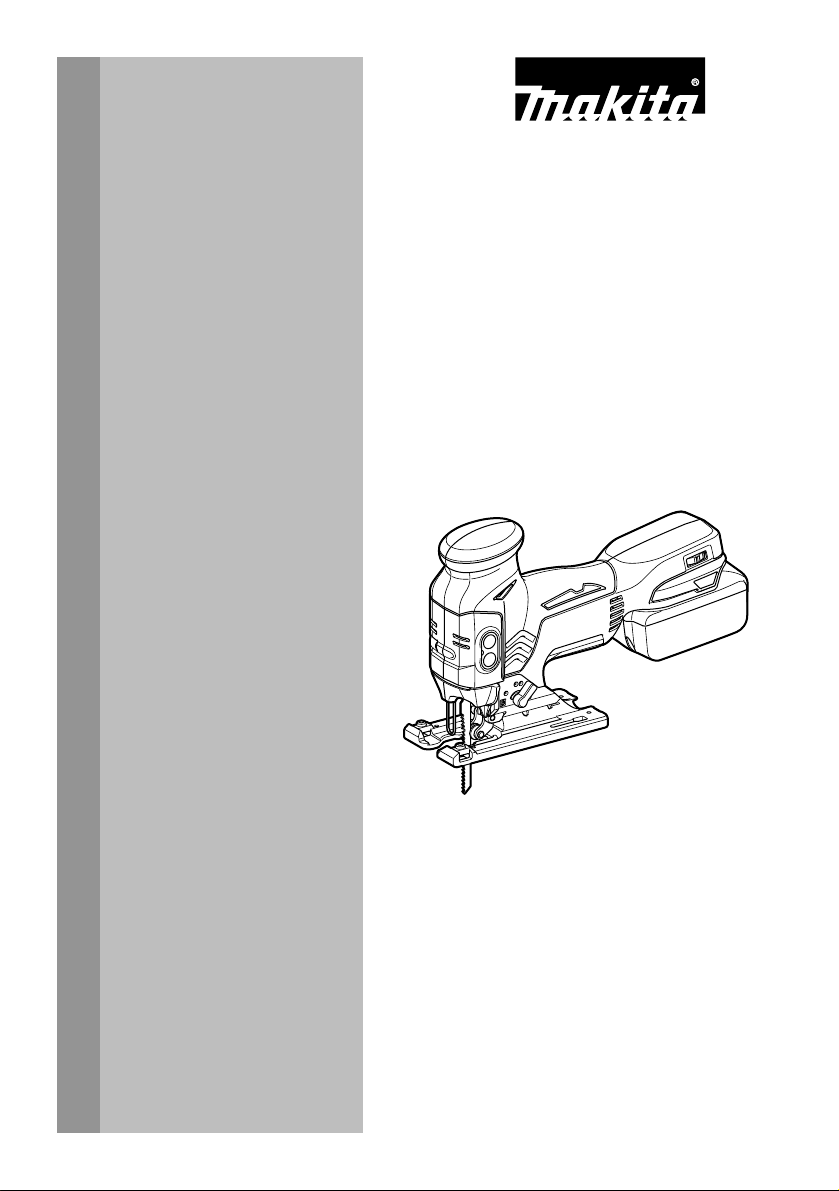
To remove the battery cartridge, slide it from the tool
while sliding the button on the front of the cartridge.
To install the battery cartridge, align the tongue on the
battery cartridge with the groove in the housing and slip
it into place. Insert it all the way until it locks in place
with a little click. If you can see the red indicator on the
upper side of the button, it is not locked completely.
CAUTION:
• Always install the battery cartridge fully until the
red indicator cannot be seen. If not, it may
accidentally fall out of the tool, causing injury to
you or someone around you.
• Do not install the battery cartridge forcibly. If the
cartridge does not slide in easily, it is not being
inserted correctly.
1. Red indicator
2. Button
3. Battery
cartridge
Battery protection system
(Lithium-ion battery with star marking)
1
012128
Lithium-ion batteries with a star marking are equipped
with a protection system. This system automatically cuts
off power to the tool to extend battery life.
The tool will automatically stop during operation if the
tool and/or battery are placed under one of the following
conditions:
• Overloaded:
The tool is operated in a manner that causes
it to draw an abnormally high current.
In this situation, press ON/OFF switch on the
tool and stop the application that caused the
tool to become overloaded. Then press
ON/OFF switch again to restart.
If the tool does not start, the battery is
overheated. In this situation, let the battery
cool before pressing ON/OFF switch again.
• Low battery voltage:
The remaining battery capacity is too low
and the tool will not operate. In this situation,
remove and recharge the battery.
1. Star marking
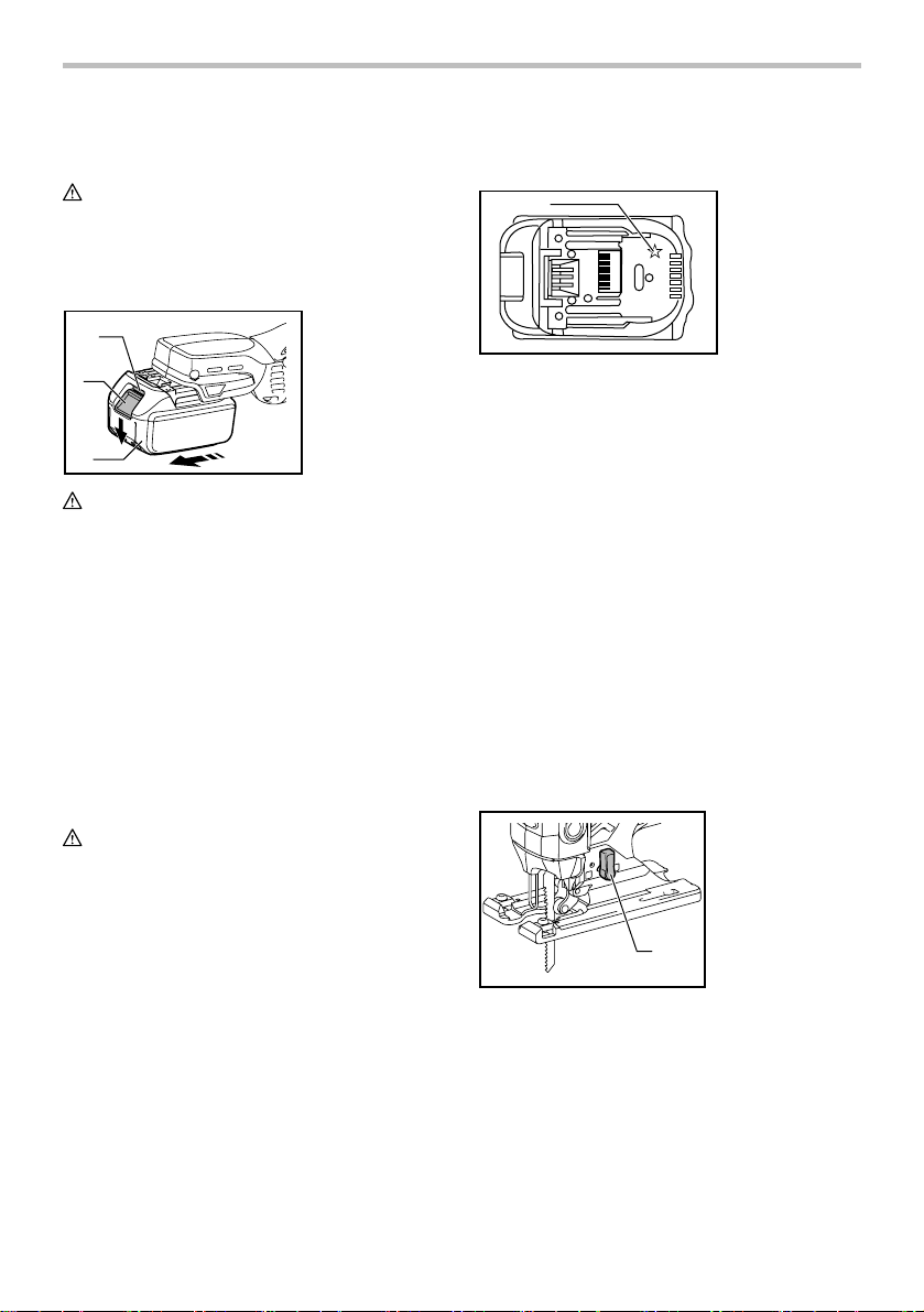
Selecting the cutting action
1. Cutting action
changing lever
1
013870
This tool can be operated with an orbital or a straight
line (up and down) cutting action. The orbital cutting
action thrusts the blade forward on the cutting stroke
and greatly increases cutting speed.
To change the cutting action, just turn the cutting action
changing lever to the desired cutting action position.
Refer to the table to select the appropriate cutting action.
5
Page 6
Position Cutting action Applications
For cutting mild steel,
stainless steel and plastics.
For clean cuts in wood
and plywood.
For cutting mild steel,
aluminum and hard wood.
For cutting wood and
plywood.
For fast cutting in
aluminum and mild steel.
For fast cutting in
wood and plywood.
006376
0
Straight line
cutting action
Small orbit
cutting action
Medium orbit
cutting action
Large orbit
cutting action
Switch action
1
2
013871
1. Lock switch
2. ON/standby
switch
• If the tool is left 10 seconds without any operations
in standby mode, the tool is automatically turned
into lock-off mode and the lamp goes off.
Lighting up the lamps
CAUTION:
• Do not look in the lamp or see the source of lamp
directly.
To turn on the lamp, press the lock switch.
Another press of the lock switch stops the tool and the
light goes off.
NOTE:
• Use a dry cloth to wipe the dirt off the lens of lamp.
Be careful not to scratch the lens of lamp, or it
may lower the illumination.
• When the tool is overheated, the lamp flickers.
Cool down the tool fully before operating again.
Speed adjusting dial
1.
Speed adjusting
1
dial
Lock-off
ON
013945
Standby
To start the tool:
Press the lock switch to turn the tool into standby mode.
It turns the lamp on, too.
Press the ON/standby switch to start the tool in standby
mode.
To stop the tool:
Press the ON/standby switch to stop and turn the tool
into standby mode.
Press the lock switch to stop and turn the tool into lockoff mode.
In standby mode, press the lock switch to turn the lamp
off and turn the tool into lock-off mode.
NOTE:
• When the tool is in standby mode, the lamp keeps
lighting.
013933
The tool speed can be infinitely adjusted by turning the
speed adjusting dial. You can get the highest speed at 6
and the lowest speed at 1.
Refer to the table to select the proper speed for the
workpiece to be cut. However, the appropriate speed
may differ with the type or thickness of the workpiece. In
general, higher speeds will allow you to cut workpieces
faster but the service life of the blade will be reduced.
Workpiece to be cut
Wood
Mild steel 3 - 6
Stainless steel 3 - 4
Aluminum 3 - 6
013925
Plastics 1 - 4
Number on adjusting dial
4 - 6
CAUTION:
• The speed adjusting dial can be turned only as far
as 6 and back to 1. Do not force it past 6 or 1, or
the speed adjusting function may no longer work.
NOTE:
• When the speed adjusting dial is at 3 or higher, the
tool automatically reduces the no-load speed to
reduce the vibration under no-load. Once the tool
gets load, the tool speed reaches the preset speed.
6
Page 7
Then the tool keeps the speed until the tool is
switched off. When temperature is low and there is
less fluidity in grease, the tool may not have this
function even with the motor rotating.
ASSEMBLY
CAUTION:
• Always be sure that the tool is switched off and the
battery cartridge is removed before carrying out
any work on the tool.
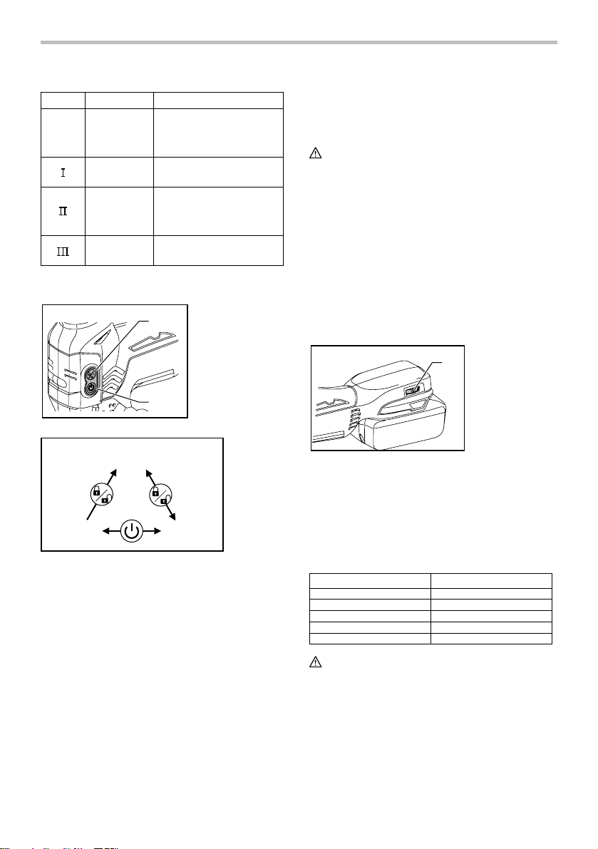
Installing or removing saw blade
CAUTION:
• Always clean out all chips or foreign matter
adhering to the blade and/or blade holder. Failure
to do so may cause insufficient tightening of the
blade, resulting in a serious personal injury.
• Do not touch the blade or the workpiece
immediately after operation; they may be
extremely hot and could burn your skin.
• Tighten the saw blade securely. Failure to do so
may cause a serious injury.
• When you remove the saw blade, be careful not to
hurt your fingers with the top of the blade or the
tips of workpiece.
1
1. Jig saw blade
1
013929
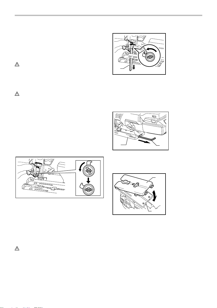
To remove the blade, push the tool opener forward as
far as it will go. This allows the blade to be released.
NOTE:
• Occasionally lubricate the roller.
Hex wrench storage
1. Base
2. Hex wrench
1
013930
When not in use, store the hex wrench as shown in the
figure to keep it from being lost.
2
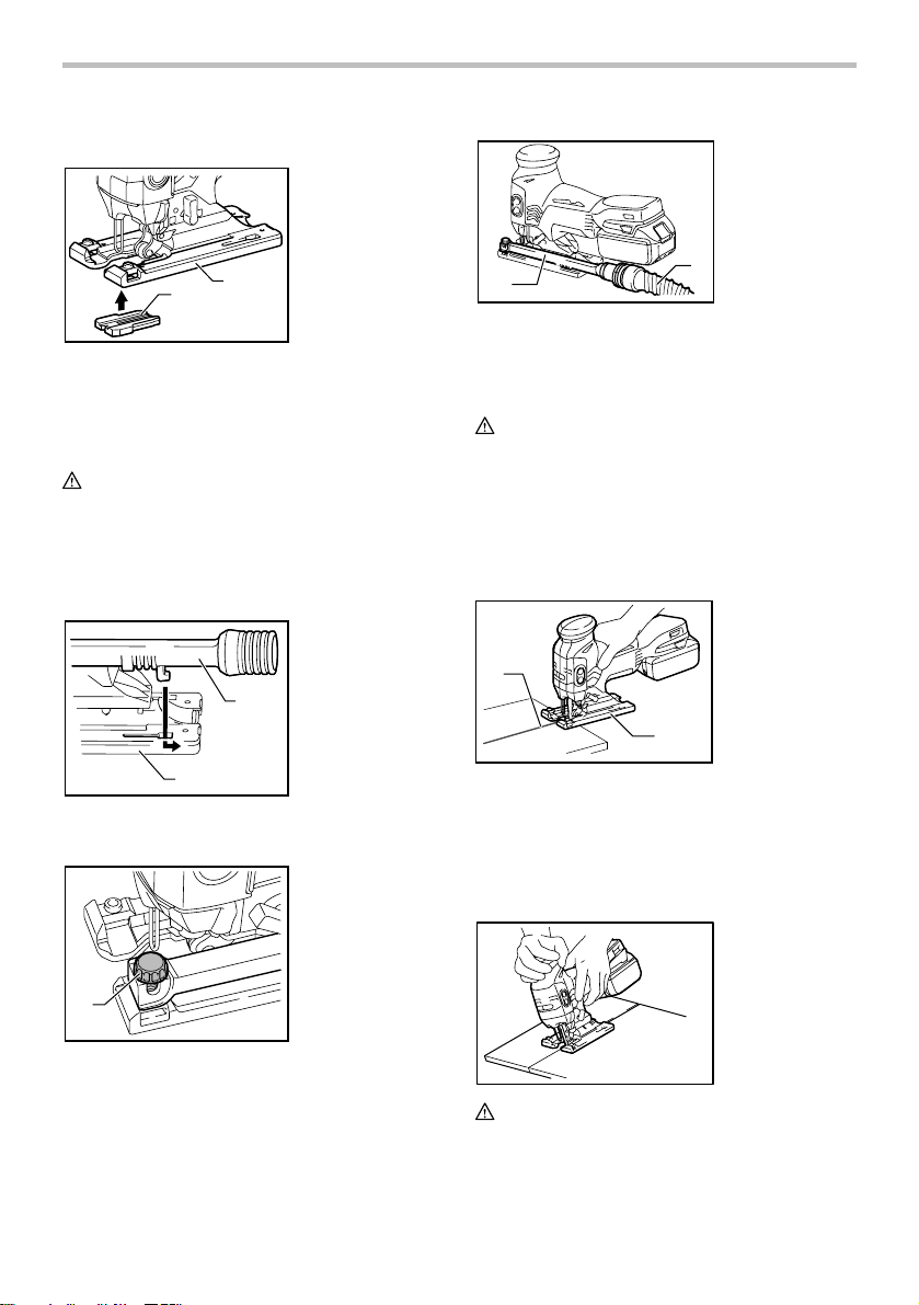
Cover plate
1. Cover plate
1
2. Base
2
1. Fixed position
2. Released position
013992
Before installing the blade, make sure that the blade
holder is in the released position.
To install the blade, insert the blade (teeth facing
forward) into the blade holder until it latches. The blade
holder moves to the fixed position by itself and the blade
is locked. Pull the blade lightly to make sure that the
blade does not fall off during operation.
CAUTION:
• Do not open the tool opener excessively, or it may
cause tool damage.
2
013876
Use the cover plate when cutting decorative veneers,
plastics, etc. It protects sensitive or delicate surfaces
from damage. Fit it on the back of the tool base.
7
Page 8
Anti-splintering device
1. Anti-splintering
device
2. Base
1. Dust nozzle
2.
Hose for
vacuum cleaner
2
1
013877
For splinter-free cuts, the anti-splintering device can be
used. To install the anti-splintering device, move the tool
base all the way forward and fit it from the back of tool
base. When you use the cover plate, install the antisplintering device onto the cover plate.
CAUTION:
• The anti-splintering device cannot be used when
making bevel cuts.
Dust extraction
The dust nozzle (optional accessory) is recommended
to perform clean cutting operations.
1. Dust nozzle
2. Base
1
2
013878
To attach the dust nozzle on the tool, insert the hook of
dust nozzle into the hole in the base.
1. Clamp screw
1
013931
Then connect a Makita vacuum cleaner to the dust
nozzle.
2
OPERATION
CAUTION:
• Always hold the base flush with the workpiece.
Failure to do so may cause blade breakage,
resulting in a serious injury.
NOTE:
• If the tool is operated continuously until the battery
cartridge has discharged, allow the tool to rest for
15 minutes before proceeding with a fresh battery.
1. Cutting line
2. Base
1
2
013932
Turn the tool on without the blade making any contact
and wait until the blade attains full speed. Then rest the
base flat on the workpiece and gently move the tool
forward along the previously marked cutting line.
When cutting curves, advance the tool very slowly.
Bevel cutting
1
013879
To secure the dust nozzle, tighten the clamp screw at
the front of the dust nozzle.
The dust nozzle can be installed on either left or right
side of the base.
013934
CAUTION:
• Always be sure that the tool is switched off and the
battery cartridge is removed before tilting the base.
With the base tilted, you can make bevel cuts at any
angle between 0° and 45° (left or right).
8
Page 9
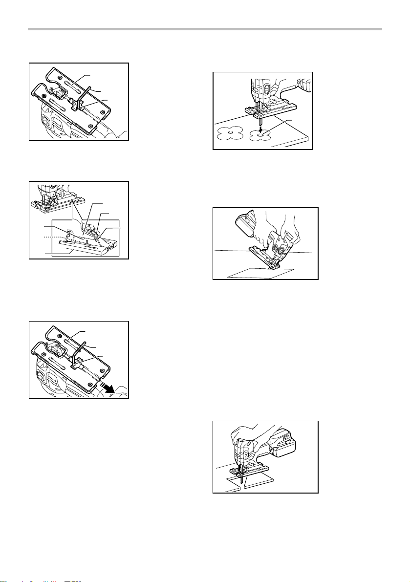
A) Boring a starting hole:
1. Starting hole
1
3
1. Base
2. Hex wrench
3. Bolt
1
2
013884
To tilt the base, loosen the bolt on the back of the base
with the hex wrench. Move the base so that the bolt is
positioned in the center of the bevel slot in the base.
1
3
2
013935
Tilt the base until the desired bevel angle is obtained.
The V-notch of the gear housing indicates the bevel
angle by graduations. Then tighten the bolt firmly to
secure the base.
1. Bevel slot
2. Base
3. Bolt
6
4. Graduations
5
5. V-notch
6. Gear housing
4
Front flush cuts
1
2
3
013886
Loosen the bolt on the back of the base with the hex
wrench and slide the base all the way back. Then
tighten the bolt to secure the base.
1. Base
2. Hex wrench
3. Bolt
Cutouts
Cutouts can be made with either of two methods A or B.
013887
For internal cutouts without a lead-in cut from an
•
edge, pre-drill a starting hole 12 mm (1/2") or more
in diameter. Insert the blade into this hole to start
your cut.
B) Plunge cutting:
013936
You need not bore a starting hole or make a lead-
•
in cut if you carefully do as follows.
1. Tilt the tool up on the front edge of the base with
the blade point positioned just above the
workpiece surface.
2. Apply pressure to the tool so that the front edge
of the base will not move when you switch on the
tool and gently lower the back end of the tool
slowly.
3. As the blade pierces the workpiece, slowly lower
the base of the tool down onto the workpiece
surface.
4. Complete the cut in the normal manner.
Finishing edges
013937
To trim edges or make dimensional adjustments, run the
blade lightly along the cut edges.
9
Page 10
Metal cutting
Always use a suitable coolant (cutting oil) when cutting
metal. Failure to do so will cause significant blade wear.
The underside of the workpiece can be greased instead
of using a coolant.
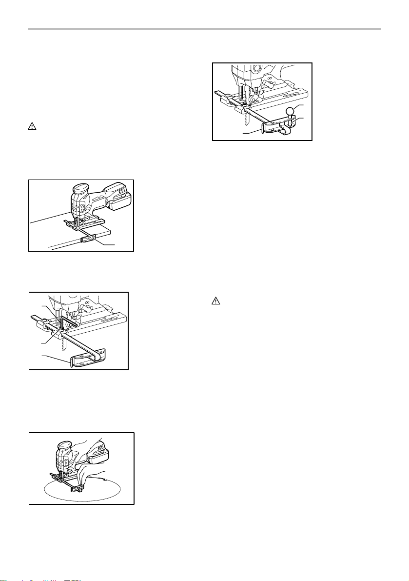
Rip fence set (optional accessory)
CAUTION:
• Always be sure that the tool is switched off and the
battery cartridge is removed before installing or
removing accessories.
1. Straight cuts
1. Rip fence
1
013938
When repeatedly cutting widths of 160 mm (6-5/16") or
less, use of the rip fence will assure fast, clean, straight
cuts.
1
2
3
013939
To install, insert the rip fence into the rectangular hole
on the side of the tool base with the fence guide facing
down. Slide the rip fence to the desired cutting width
position, then tighten the bolt to secure it.
2. Circular cuts
1. Hex wrench
2. Bolt
3. Fence guide
1. Fence guide
2. Threaded knob
3. Circular guide pin
2
3
1
013941
When cutting circles or arcs of 170 mm (6-11/16") or
less in radius, install the rip fence as follows.
1. Insert the rip fence into the rectangular hole on
the side of the base with the fence guide facing
up. Insert the circular guide pin through either of
the two holes on the fence guide. Screw the
threaded knob onto the pin to secure the pin.
2. Now slide the rip fence to the desired cutting
radius, and tighten the bolt to secure it in place.
Then move the base all the way forward.
NOTE:
• Always use blades No. B-17, B-18, B-26 or B-27
when cutting circles or arcs.
MAINTENANCE
CAUTION:
• Always be sure that the tool is switched off and the
battery cartridge is removed before attempting to
perform inspection or maintenance.
• Never use gasoline, benzine, thinner, alcohol or
the like. Discoloration, deformation or cracks may
result.
To maintain product SAFETY and RELIABILITY, repairs,
any other maintenance or adjustment should be
performed by Makita Authorized or Factory Service
Centers, always using Makita replacement parts.
013940
10
Page 11

OPTIONAL ACCESSORIES
CAUTION:
• These accessories or attachments are
recommended for use with your Makita tool
specified in this manual. The use of any other
accessories or attachments might present a risk of
injury to persons. Only use accessory or
attachment for its stated purpose.
If you need any assistance for more details regarding
these accessories, ask your local Makita Service Center.
• Jig saw blades
• Hex wrench 4
• Rip fence (guide rule) set
• Anti-splintering device
• Cover plate
• Dust nozzle assy
• Makita genuine battery and charger
NOTE:
• Some items in the list may be included in the tool
package as standard accessories. They may differ
from country to country.
MAKITA LIMITED ONE YEAR WARRANTY
Warranty Policy
Every Makita tool is thoroughly inspected and tested
before leaving the factory. It is warranted to be free of
defects from workmanship and materials for the period
of ONE YEAR from the date of original purchase.
Should any trouble develop during this one year period,
return the COMPLETE tool, freight prepaid, to one of
Makita’s Factory or Authorized Service Centers. If
inspection shows the trouble is caused by defective
workmanship or material, Makita will repair (or at our
option, replace) without charge.
This Warranty does not apply where:
repairs have been made or attempted by others:
repairs are required because of normal wear and
tear:
the tool has been abused, misused or improperly
maintained:
alterations have been made to the tool.
IN NO EVENT SHALL MAKITA BE LIABLE FOR ANY
INDIRECT, INCIDENTAL OR CONSEQUENTIAL
DAMAGES FROM THE SALE OR USE OF THE
PRODUCT. THIS DISCLAIMER APPLIES BOTH
DURING AND AFTER THE TERM OF THIS
WARRANTY.
MAKITA DISCLAIMS LIABILITY FOR ANY IMPLIED
WARRANTIES, INCLUDING IMPLIED WARRANTIES
OF "MERCHANTABILITY" AND "FITNESS FOR A
SPECIFIC PURPOSE," AFTER THE ONE YEAR TERM
OF THIS WARRANTY.
This Warranty gives you specific legal rights, and you
may also have other rights which vary from state to
state. Some states do not allow the exclusion or
limitation of incidental or consequential damages, so
the above limitation or exclusion may not apply to you.
Some states do not allow limitation on how long an
implied warranty lasts, so the above limitation may not
apply to you.
EN0006-1
11
Page 12

FRANÇAIS (Mode d’emploi original)
SPÉCIFICATIONS
Modèle DJV181
Longueur de frappe 26 mm (1")
Capacités de coupe max.
Nombre d'impacts par minute 800 - 3 500 /min
Longueur totale 298 mm (11-3/4")
Poids net 2,5 kg (5,5 lbs)
Tension nominale C.C. 18 V
Avertissement : Utilisez seulement la/les batterie(s) décrite(s).
• Étant donné l'évolution constante de notre programme de recherche et de développement, les spécifications contenues dans ce
manuel sont sujettes à modification sans préavis.
• Les spécifications peuvent varier suivant les pays.
• Poids conforme à la procédure EPTA du 01/2003
Batterie(s) standard(s)
Consignes de sécurité générales
pour outils électriques
MISE EN GARDE Veuillez lire toutes les mises
en garde de sécurité et toutes les instructions.
L'ignorance des mises en garde et des instructions
comporte un risque de choc électrique, d'incendie et/ou
de blessure grave.
Conservez toutes les mises en
garde et instructions pour
référence future.
Le terme ≪ outil électrique ≫ qui figure dans les
avertissements fait référence à un outil électrique
branché sur une prise de courant (par un cordon
d'alimentation) ou alimenté par batterie (sans fil).
Sécurité de la zone de travail
1. Maintenez la zone de travail propre et bien
éclairée. Les zones de travail encombrées ou
sombres ouvrent grande la porte aux accidents.
2. N'utilisez pas les outils électriques dans les
atmosphères explosives, par exemple en
présence de liquides, gaz ou poussières
inflammables. Les outils électriques produisent
des étincelles au contact desquelles la poussière
ou les vapeurs peuvent s'enflammer.
3. Assurez-vous qu'aucun enfant ou curieux ne
s'approche pendant que vous utilisez un outil
électrique. Vous risquez de perdre la maîtrise de
l'outil si votre attention est détournée.
Bois 135 mm (5-5/16")
Acier doux 10 mm (3/8")
Aluminium 20 mm (25/32")
BL1830 / BL1840
Les risques de choc électrique sont moindres
GEA006-2
Sécurité en matière d'électricité
4. Les fiches d'outil électrique sont conçues
pour s'adapter parfaitement aux prises de
courant. Ne modifiez jamais la fiche de
quelque façon que ce soit. N'utilisez aucun
adaptateur de fiche sur les outils électriques
avec mise à la terre. En ne modifiant pas les
fiches et en les insérant dans des prises de
courant pour lesquelles elles ont été conçues
vous réduirez les risques de choc électrique.
5. Évitez tout contact corporel avec les surfaces
mises à la terre, telles que les tuyaux,
radiateurs, cuisinières et réfrigérateurs. Le
risque de choc électrique est plus élevé si votre
corps se trouve mis à la terre.
6. N'exposez pas les outils électriques à la pluie
ou à l'eau. La présence d'eau dans un outil
électrique augmente le risque de choc électrique.
7.
Ne maltraitez pas le cordon. N'utilisez jamais le
cordon pour transporter, tirer ou débrancher
l'outil électrique. Maintenez le cordon à l'écart
des sources de chaleur, de l'huile, des objets à
bords tranchants et des pièces en mouvement.
risque de choc électrique est plus élevé lorsque les
cordons sont endommagés ou enchevêtrés.
8.
Lorsque vous utilisez un outil électrique à
l'extérieur, utilisez un cordon prolongateur prévu à
cette fin.
lorsqu'un cordon conçu pour l'extérieur est utilisé.
9. Si vous devez utiliser un outil électrique dans
un endroit humide, utilisez une source
d'alimentation protégée par un disjoncteur de
fuite à la terre. L'utilisation d'un disjoncteur de
fuite à la terre réduit le risque de choc électrique.
12
Le
Page 13

Sécurité personnelle
10. Restez alerte, attentif à vos mouvements et
faites preuve de bon sens lorsque vous
utilisez un outil électrique. Évitez d'utiliser un
outil électrique si vous êtes fatigué ou si vous
avez pris une drogue, de l'alcool ou un
médicament. Un moment d'inattention pendant
l'utilisation d'un outil électrique peut entraîner une
grave blessure.
11. Portez des dispositifs de protection
personnelle. Portez toujours un protecteur
pour la vue. Les risques de blessure seront
moins élevés si vous utilisez des dispositifs de
protection tels qu'un masque antipoussières, des
chaussures à semelle antidérapante, une coiffure
résistante ou une protection d'oreilles.
12. Évitez les démarrages accidentels. Assurez-
vous que l’interrupteur soit en position d'arrêt
avant de brancher l'outil à la prise électrique
et/ou au bloc-piles, avant de prendre ou de
transporter l’outil. Vous ouvrez la porte aux
accidents si vous transportez les outils
électriques avec le doigt sur l’interrupteur ou si
vous les branchez alors que l’interrupteur est en
position de marche.
13. Retirez toute clé de réglage ou de serrage
avant de mettre l'outil sous tension. Tout e cl é
laissée en place sur une pièce rotative de l'outil
électrique peut entraîner une blessure.
14. Maintenez une bonne position. Assurez-vous
d'une bonne prise au sol et d'une bonne
position d'équilibre en tout temps. Cela vous
permettra d'avoir une meilleure maîtrise de l'outil
dans les situations imprévues.
15. Portez des vêtements adéquats. Ne portez ni
vêtements amples ni bijoux. Vous devez
maintenir cheveux, vêtements et gants à
l'écart des pièces en mouvement. Les pièces
en mouvement peuvent happer les vêtements
amples, les bijoux et les cheveux longs.
16. Si des accessoires sont fournis pour
raccorder un appareil d'aspiration et de
collecte de la poussière, assurez-vous qu'ils
sont correctement raccordés et qu'ils sont
utilisés de manière adéquate. L'utilisation d'un
appareil d'aspiration permet de réduire les
risques liés à la présence de poussière dans l'air.
Utilisation et entretien des outils électriques
17. Ne forcez pas l'outil électrique. Utilisez l'outil
électrique adéquat suivant le type de travail à
effectuer. Si vous utilisez l'outil électrique
adéquat et respectez le régime pour lequel il a
été conçu, il effectuera un travail de meilleure
qualité et de façon plus sécuritaire.
18. N'utilisez pas l'outil électrique s'il n'est pas
possible de mettre sa gâchette en position de
marche et d'arrêt. Un outil électrique dont
l'interrupteur est défectueux représente un
danger et doit être réparé.
19.
Débranchez la fiche de la source d'alimentation
et/ou retirez le bloc-piles de l'outil électrique
avant d'effectuer tout réglage, de changer un
accessoire ou de ranger l'outil électrique.
telles mesures préventives réduisent les risques de
démarrage accidentel de l'outil électrique.
20.
Après l'utilisation d'un outil électrique, rangez-le
hors de portée des enfants et ne laissez aucune
personne l'utiliser si elle n'est pas familiarisée
avec l'outil électrique ou les présentes
instructions d'utilisation.
Les outils électriques
représentent un danger entre les mains de personnes
qui n'en connaissent pas le mode d'utilisation.
21.
Veillez à l’entretien des outils électriques.
Assurez-vous que les pièces mobiles ne sont pas
désalignées ou coincées, qu’aucune pièce n’est
cassée et que l’outil électrique n’a subi aucun
dommage affectant son bon fonctionnement. Le
cas échéant, faites réparer l'outil électrique avant
de l'utiliser.
De nombreux accidents sont causés par
des outils électriques mal entretenus.
22. Maintenez les outils tranchants bien aiguisés
et propres. Un outil tranchant dont l'entretien est
effectué correctement et dont les bords sont bien
aiguisés risquera moins de se coincer et sera
plus facile à maîtriser.
23.
Utilisez l'outil électrique, ses accessoires, ses
embouts, etc., en respectant les présentes
instructions, en tenant compte des conditions de
travail et du type de travail à effectuer.
L'utilisation
d'un outil électrique à des fins autres que celles
prévues peut entraîner une situation dangereuse.
Utilisation et entretien des outils alimentés par
batterie
24. Pour recharger, utilisez uniquement le
chargeur spécifié par le fabricant. L'utilisation
d'un chargeur conçu pour un type donné de blocpiles comporte un risque d'incendie lorsqu'il est
utilisé avec un autre type de bloc-piles.
25. N'utilisez un outil électrique qu'avec le bloc-
piles conçu spécifiquement pour cet outil. Il y
a risque de blessure ou d'incendie si un autre
bloc-piles est utilisé.
26. Lorsque vous n'utilisez pas le bloc-piles,
rangez-le à l'écart des objets métalliques tels
que trombones, pièces de monnaie, clés,
clous, vis ou autres petits objets métalliques
qui risquent d'établir une connexion entre les
bornes. La mise en court-circuit des bornes de
batterie peut causer des brûlures ou un incendie.
13
De
Page 14

27. Dans des conditions d'utilisation inadéquates
de la batterie, il peut y avoir fuite d'électrolyte;
évitez tout contact avec ce liquide. En cas de
contact accidentel, rincez avec beaucoup
d’eau. Si le liquide pénètre dans vos yeux, il
faut aussi consulter un médecin. L'électrolyte
qui s'échappe de la batterie peut causer des
irritations ou des brûlures.
Réparation
28. Faites réparer votre outil électrique par un
réparateur qualifié qui utilise des pièces de
rechange identiques aux pièces d'origine. Le
maintien de la sûreté de l'outil électrique sera
ainsi assuré.
29. Suivez les instructions de lubrification et de
changement des accessoires.
30. Maintenez les poignées de l'outil sèches,
propres et exemptes d'huile ou de graisse.
GEB045-2
CONSIGNES DE SÉCURITÉ
POUR LA SCIE SAUTEUSE
SANS FIL
1.
Tenez l'outil par ses surfaces de prise isolées
pendant toute opération où l’accessoire de
coupe pourrait venir en contact avec un câblage
dissimulé.
sous tension, les pièces métalliques à découvert de
l'outil pourraient devenir sous tension et risqueraient
de transmettre une décharge électrique à l'utilisateur.
2. Utilisez des dispositifs de serrage ou un autre
moyen pratique pour fixer la pièce à une
surface de travail stable. La pièce sera instable
et vous risquerez d'en perdre la maîtrise si vous
la tenez avec une main ou l'appuyez simplement
contre une partie du corps.
3. Portez toujours des lunettes de sécurité ou
des lunettes à coques. Les lunettes ordinaires
et les lunettes de soleil ne sont PAS des
lunettes de sécurité.
4. Évitez les clous. Avant de commencer à scier,
vérifiez la pièce pour en retirer tous les clous.
5. Ne sciez pas de pièces dont le diamètre
dépasse la capacité de coupe de la scie.
6. Avant de commencer la coupe, assurez-vous
qu'il y a suffisamment d'espace sous la pièce
pour que la lame ne heurte pas le plancher,
l'établi, etc.
7. Tenez l'outil fermement.
8. Assurez-vous que la lame n'entre pas en
contact avec la pièce avant de mettre l'outil
sous tension.
9. Gardez vos mains éloignées des pièces
mobiles.
En cas de contact avec un conducteur
10. N'abandonnez pas l'outil alors qu'il tourne. Ne
faites fonctionner l'outil qu'une fois que vous
l'avez bien en main.
11. Avant de retirer la lame de la pièce, coupez
toujours le contact et attendez l'arrêt complet
de la lame.
12. Ne touchez ni la lame ni la pièce
immédiatement après la coupe. Elles risquent
d'être extrêmement chaudes et de vous brûler
la peau.
13. Ne faites pas tourner inutilement l'outil à vide.
14. Certains matériaux contiennent des produits
chimiques qui peuvent être toxiques. Prenez
les précautions nécessaires pour éviter
l'inhalation de ces poussières ou leur contact
avec la peau. Conformez-vous aux consignes
de sécurité du fournisseur du matériau.
15. Utilisez toujours un masque antipoussières
ou un masque filtrant approprié au matériau à
travailler et à l'outil utilisé.
CONSERVEZ CE MODE D'EMPLOI.
AVERTISSEMENT:
NE VOUS LAISSEZ PAS tromper (au fil d'une
utilisation répétée) par un sentiment d'aisance ou
de familiarité avec le produit en négligeant les
consignes de sécurité qui accompagnent le produit.
L'utilisation non sécuritaire ou incorrecte de cet
outil comporte un risque de blessure grave.
USD301-1
Symboles
Les symboles utilisés pour l'outil sont indiqués cidessous.
・ volts
・ courant continu
・ vitesse à vide
・ tours ou alternances par minute
ENC007-8
CONSIGNES DE SÉCURITÉ
IMPORTANTES
POUR LA BATTERIE
1. Avant d'utiliser la batterie, lisez toutes les
instructions et précautions relatives (1) au
chargeur de batterie, (2) à la batterie, et (3) à
l'outil utilisant la batterie.
2. Ne démontez pas la batterie.
14
Page 15

3. Cessez immédiatement l'utilisation si le temps
de fonctionnement devient excessivement
court. Il y a risque de surchauffe, de brûlures,
voire d'explosion.
4. Si l'électrolyte pénètre dans vos yeux, rincezles à l'eau claire et consultez immédiatement
un médecin. Il y a risque de perte de la vue.
5. Ne court-circuitez pas la batterie :
(1) Ne touchez les bornes avec aucun
matériau conducteur.
(2)
Évitez de ranger la batterie dans un conteneur
avec d'autres objets métalliques, par exemple
des clous, des pièces de monnaie, etc.
(3) Évitez d'exposer la batterie à l'eau ou à la
pluie.
Un court-circuit de la batterie pourrait
provoquer un fort courant, une surchauffe,
parfois des brûlures et même une panne.
6. Ne rangez pas l'outil ou la batterie dans des
endroits où la température risque d'atteindre
ou de dépasser 50 ゚ C (122 ゚ F).
7. Ne jetez pas la batterie au feu même si elle est
sérieusement endommagée ou complètement
épuisée. La batterie peut exploser au contact
du feu.
8.
Prenez garde d'échapper ou de heurter la batterie.
9. N'utilisez pas une batterie si elle est
endommagée.
10. Suivez la réglementation locale concernant la
mise au rebut de la batterie.
CONSERVEZ CE MODE
D'EMPLOI.
Conseils pour obtenir la durée de service
maximale de la batterie
1. Rechargez la batterie avant qu'elle ne soit
complètement déchargée.
Arrêtez toujours l'outil et rechargez la batterie
quand vous remarquez que la puissance de
l'outil diminue.
2. Ne rechargez jamais une batterie
complètement chargée.
La surcharge réduit la durée de service de la
batterie.
3. Rechargez la batterie à une température
ambiante comprise entre 10 ゚ C et 40 ゚ C (50 ゚
F - 104 ゚ F). Si la batterie est chaude, laissezla refroidir avant de la recharger.
4. Rechargez la batterie tous les six mois si
l'appareil n'est pas utilisé pendant de longues
périodes.
DESCRIPTION DU
FONCTIONNEMENT
ATT EN TI ON :
• Assurez-vous toujours que l'outil est hors tension
et que sa batterie est retirée avant de l'ajuster ou
de vérifier son fonctionnement.
Installation ou retrait de la batterie
1.
1
2
3
013928
ATT EN TI ON :
• Mettez toujours l'appareil hors tension avant
d'installer ou de retirer la batterie.
• Tenez fermement l'outil et la batterie lors de
l'installation ou du retrait de cette dernière.
Sinon, l'outil et la batterie pourraient vous glisser
des mains, ce qui risque d'endommager l'outil et la
batterie, ou encore de provoquer des blessures.
Pour retirer la batterie, faites-la glisser de l'outil tout en
faisant glisser le bouton se trouvant à l'avant.
Pour installer la batterie, alignez sa languette sur la
rainure pratiquée dans le boîtier, et glissez la batterie en
place. Insérez-la à fond jusqu'à ce que vous entendiez
un clic. Si vous pouvez voir l'indicateur rouge situé sur
le dessus du bouton, la batterie n'est pas complètement
verrouillée.
ATT EN TI ON :
• Installez toujours la batterie à fond jusqu’à ce que
vous ne puissiez plus voir l’indicateur rouge. Dans
le cas contraire, elle pourrait tomber de l'outil et
entraîner des blessures.
• Ne forcez pas sur la batterie pour l'installer. Si la
batterie ne glisse pas facilement, c'est qu'elle n'est
pas insérée correctement.
Indicateur rouge
2. Bouton
3. Batterie
15
Page 16

Système de protection de la batterie
(batterie lithium-ion marquée d’une étoile)
1
012128
Les batteries lithium-ion marquées d’une étoile sont
équipées d’un système de protection. Ce système
coupe automatiquement l’alimentation de l’outil pour
augmenter la durée de vie de la batterie.
L'outil s'arrête automatiquement pendant l'utilisation
lorsque l'outil et/ou la batterie sont dans l'une des
situations suivantes :
• En surcharge :
L'outil est utilisé d'une manière entraînant
une consommation anormale de courant.
Dans cette situation, appuyez sur
l’interrupteur ON/OFF de l’outil et arrêtez
l'activité qui entraîne une surcharge de l'outil.
Puis, appuyez à nouveau sur l’interrupteur
ON/OFF pour redémarrer.
Si l’outil ne démarre pas, la batterie est en
surchauffe. Dans cette situation, laissez la
batterie refroidir avant d’appuyer à nouveau
sur l’interrupteur ON/OFF.
• Tension de la batterie faible :
La capacité restante de la batterie est trop
faible pour que l'outil puisse fonctionner. Dans
cette situation, retirez et rechargez la batterie.
1. Étoile
Sélection du mouvement de coupe
1. Levier de
sélection du
mouvement de
coupe
1
013870
Cet outil peut être utilisé avec un mouvement de coupe
orbital ou rectiligne (haut et bas). Le mouvement de
coupe orbital pousse la lame vers l'avant pendant sa
course, augmentant considérablement la vitesse de
coupe.
Pour modifier le mouvement de coupe, tournez
simplement le levier de sélection du mouvement de
coupe sur la position de mouvement de coupe désirée.
Consultez le tableau pour sélectionner le mouvement
de coupe approprié.
Position
006376
Mouvement de coupe
Mouvement de
0
coupe rectiligne
Mouvement de
coupe à petite
orbite
Mouvement de
coupe à moyenne
orbite
Mouvement de
coupe à grande
orbite
Applications
Pour couper l'acier doux, l'acier
inoxydable et le plastique.
Pour des coupes nettes dans le
bois et le contreplaqué.
Pour couper l'acier doux,
l'aluminium et le bois dur.
Pour couper le bois et le
contreplaqué.
Pour la coupe rapide de
l'aluminium et de l'acier doux.
Pour la coupe rapide du bois et
du contreplaqué.
Interrupteur
1
2
013871
Sécurité
MARCHE
013945
Pour démarrer l’outil :
Appuyez sur l’interrupteur de verrouillage pour mettre
l’outil en mode veille. La lampe s'allume également.
Appuyez sur l’interrupteur ON/veille pour démarrer l'outil
en mode veille.
Pour arrêter l’outil :
Appuyez sur l’interrupteur ON/veille pour arrêter et
mettre l’outil en mode veille.
Appuyez sur l’interrupteur de verrouillage pour arrêter et
mettre l’outil en mode de sécurité.
En mode veille, appuyez sur l’interrupteur de
verrouillage pour éteindre la lampe et mettre l’outil en
mode de sécurité.
1. Interrupteur de
verrouillage
2. Interrupteur
ON/veille
Veille
16
Page 17

NOTE:
• Lorsque l’outil est en mode veille, la lampe reste
allumée.
• Si l’outil reste 10 secondes inactif en mode veille,
il se met automatiquement en mode de sécurité et
la lampe s’éteint.
Allumage de la lampe
ATT EN TI ON :
• Ne regardez pas la lampe et n'observez pas la
source de lumière directement.
Pour allumer la lampe, appuyez sur l’interrupteur de
verrouillage.
Si vous appuyez encore une fois sur l’interrupteur de
verrouillage, l’outil s’arrête et la lampe s’éteint.
NOTE:
• Utilisez un chiffon sec pour essuyer la saleté qui
recouvre la lentille de la lampe. Prenez garde de
rayer la lentille de la lampe, pour éviter une
diminution de l'éclairage.
• Lorsque l'outil est surchauffé, la lampe clignote.
Refroidissez l'outil complètement avant de le
réutiliser.
Cadran de rélage de vitesse
1. Cadran de
1
réglage de la
vitesse
013933
La vitesse de l’outil peut être librement réglée à l'aide
du cadran de réglage de vitesse. Vous pouvez obtenir la
vitesse la plus élevée sur 6 et la plus basse sur 1.
Référez-vous au tableau pour sélectionner la vitesse qui
convient à la pièce à couper. La vitesse adéquate peut
toutefois varier suivant le type de matériau ou
l'épaisseur de la pièce. En général, les vitesses rapides
permettent de couper les pièces plus rapidement, mais
cela réduit la durée de service de la lame.
Pièce à couper
Bois
Acier doux 3 - 6
Acier inoxydable 3 - 4
Aluminium 3 - 6
Plastique 1 - 4
013925
Numéro sur le cadran de réglage
4 - 6
ATT EN TI ON :
• Le cadran de réglage de la vitesse ne peut pas
dépasser le 6 et le 1. Ne le forcez pas à dépasser
le 6 ou le 1, sinon la fonction de réglage de la
vitesse risque de ne plus fonctionner.
NOTE:
• Lorsque le cadran de réglage de vitesse est sur 3
ou plus, l’outil réduit automatiquement la vitesse à
vide pour réduire la vibration quand il est à vide.
Une fois que l’outil se charge, la vitesse de l’outil
atteint la vitesse préréglée. Puis, l'outil garde la
même vitesse jusqu’à ce que vous le mettiez hors
tension. Lorsque la fluidité de la graisse diminue
en raison de la basse température, il se peut que
cette fonction soit inopérante même si le moteur
tourne.
ASSEMBLAGE
ATT EN TI ON :
• Assurez-vous toujours que l'outil est hors tension
et que sa batterie est retirée avant d'effectuer tout
travail dessus.
Pose et retrait de la lame de scie
ATT EN TI ON :
• Nettoyez toujours la lame et/ou le porte-lame de
tous les copeaux ou corps étrangers qui y
adhèrent. Négliger ce nettoyage peut causer un
serrage insuffisant de la lame qui risque
d'entraîner une grave blessure.
• Ne touchez ni la lame ni la pièce immédiatement
après l'opération ; elles peuvent être extrêmement
chaudes et risquent de vous brûler la peau.
• Serrez la lame fermement. Sinon, il y a risque de
blessure grave.
• Lors de la dépose de la lame, prenez garde de
vous blesser aux doigts avec l'extrémité de la
lame ou les bouts de la pièce.
1
2
1. Position d'immobilisation
2. Position ouverte
013992
Avant l’installation de la lame, assurez-vous que le
porte-lame est dans la position dégagée.
17
Page 18

Pour installer la lame, insérez celle-ci (dents tournées
vers l’avant) dans le porte-lame, jusqu’à ce qu’elle
s’enclenche. Le porte-lame retourne seul dans la
position engagée et la lame est alors verrouillée. Tirez
légèrement sur la lame pour vous assurer que celle-ci
ne risque pas de tomber durant le fonctionnement.
ATT EN TI ON :
• Ne déployez pas l'ouverture de l'outil de manière
excessive, pour éviter d'endommager l'outil.
1. Lame de scie
sauteuse
1
013929
Pour retirer la lame, poussez l’ouverture de l’outil jusqu’au
bout de sa course. Cela permet de dégager la lame.
NOTE:
• Lubrifier le rouleau de temps à autre.
Rangement de la clé hexagonale
1. Base
2. Clé hexagonale
Dispositif anti-fente
1. Dispositif antifente
2. Base
2
1
013877
Vous pouvez utiliser le dispositif anti-fente pour obtenir
des coupes sans fente. Pour l'installer, déplacez la base
de l'outil complètement vers l'avant, puis installez le
dispositif par l'arrière de la base de l'outil. Lorsque vous
utilisez la plaque de recouvrement, installez le dispositif
anti-fente sur cette dernière.
ATT EN TI ON :
• L'utilisation du dispositif anti-fente n'est pas
possible lors des coupes en biseau.
Collecte de la poussière
Le raccord d'aspiration (accessoire en option) est
recommandé pour l'exécution d'opérations de coupe
propres.
1. Raccord à
poussières
2. Base
1
1
013930
2
Lorsque vous n'utilisez pas la clé hexagonale, rangez-la de
la façon indiquée sur l'illustration pour éviter de l'égarer.
Plaque de recouvrement
1. Plaque de
1
2
013876
Utilisez la plaque de recouvrement pour la coupe des
placages décoratifs, du plastique, etc. Cette plaque
protège contre les dommages les surfaces fragiles ou
délicates. Installez-la par l'arrière de la base de l'outil.
recouvrement
2. Base
2
013878
Pour fixer le raccord d'aspiration sur l'outil, insérez le
crochet du raccord d'aspiration dans l'orifice de la base.
1. Vis de serrage
1
013879
Pour fixer le raccord d’aspiration, serrez la vis de
serrage à l’avant du raccord d’aspiration.
Le raccord d'aspiration peut être installé du côté gauche
ou droit de la base.
18
Page 19

1. Raccord à
poussières
2. Tuyau
d'aspirateur
1
013931
Raccordez ensuite un aspirateur Makita au raccord
d'aspiration.
2
UTILISATION
ATT EN TI ON :
• Maintenez toujours la base parfaitement en
contact avec la pièce. Sinon, la lame risque de se
briser et de causer une grave blessure.
NOTE:
• Si l'outil est utilisé de manière continue jusqu'à ce
que la batterie soit déchargée, laissez-le reposer
15 minutes avant de poursuivre l'opération avec
une batterie fraîche.
1. Ligne de coupe
2. Base
1
2
013932
Mettez l'outil sous tension alors que la lame n'entre en
contact avec aucune surface, et attendez qu'elle ait
atteint sa pleine vitesse. Posez ensuite la base à plat
sur la pièce et faites avancer l'outil doucement le long
de la ligne de coupe préalablement tracée.
Faites avancer l'outil très lentement lors de la coupe de
courbes.
Coupe en biseau
ATT EN TI ON :
• Assurez-vous toujours que l'outil est hors tension
et que la batterie est retirée avant d'incliner la
base.
Avec la base inclinée, vous pouvez faire des coupes en
biseau de n'importe quel angle, entre 0° et 45° (gauche
ou droite).
1
2
013884
Pour incliner la base, desserrez le boulon à l’arrière de
la base avec la clé hexagonale. Déplacez la base de
sorte que le boulon soit positionné au centre de la fente
de biseau sur la base.
1
3
2
013935
Inclinez la base jusqu'à l'angle de coupe en biseau
désiré. L'entaille en V du carter d'engrenages indique
l'angle de biseau au moyen de graduations. Serrez
ensuite le boulon fermement pour fixer la base.
1. Base
2. Clé hexagonale
3. Boulon
3
1. Fente en biseau
2. Base
3. Boulon
6
4. Graduations
5
5. Encoche en V
6. Carter
4
d'engrenage
Coupes à ras vers l'avant
1
2
3
1. Base
2. Clé hexagonale
3. Boulon
013934
013886
Utilisez la clé hexagonale pour desserrer le boulon à
l'arrière de la base, et faites glisser la base
complètement vers l'arrière. Serrez ensuite le boulon
pour fixer la base.
19
Page 20

Découpage
Le découpage peut s'effectuer par la méthode A ou B.
A) Perçage d'un trou de départ :
1. Trou de départ
1
013887
Pour le découpage interne sans coupe
•
d'introduction à partir du bord, percez d'abord un
trou de départ de 12 mm (1/2") ou plus de
diamètre. Insérez la lame dans ce trou pour
commencer la coupe.
B) Coupe en plongée :
013936
Si vous procédez soigneusement de la façon qui
•
suit, il n'est pas nécessaire de percer un trou de
départ ou d'effectuer une coupe d'introduction.
1. Inclinez l'outil vers le bord avant de la base, le
bout de la lame se trouvant juste au-dessus de la
surface de la pièce.
2. Appliquez une pression sur l'outil, de sorte que le
bord avant de la base ne bouge pas lorsque vous
mettrez l'outil sous tension, puis abaissez
doucement l'arrière de l'outil.
3. A mesure que la lame pénètre dans la pièce,
abaissez lentement la base de l'outil sur la
surface de la pièce.
4. Complétez ensuite la coupe de façon normale.
Finition des bords
013937
Pour égaliser les bords ou pour ajuster les dimensions,
faites passer la lame légèrement le long des bords coupés.
Coupe du métal
Utilisez toujours un fluide de refroidissement (huile de
coupe) adéquat lors de la coupe du métal. Autrement,
cela usera considérablement la lame. Au lieu d'utiliser
un fluide de refroidissement pour la face inférieure de la
pièce, vous pouvez la recouvrir de graisse.
Ensemble de garde parallèle
(accessoire en option)
ATT EN TI ON :
• Assurez-vous toujours que l'outil est hors tension
et que sa batterie est retirée avant d'installer ou de
retirer des accessoires.
1. Coupes rectilignes
1. Garde parallèle
1
013938
Lorsque vous taillez des morceaux dont la largeur est
de 160 mm (6-5/16") ou moins, utilisez le garde
parallèle pour assurer une coupe droite, rapide et
propre.
1
2
3
013939
Pour l’installer, insérez le garde parallèle dans l’orifice
rectangulaire sur le côté de la base de l'outil, en
orientant le garde parallèle vers le bas. Faites glisser le
garde parallèle sur la position correspondant à la
largeur de coupe désirée, puis serrez le boulon pour le
fixer.
20
1. Clé hexagonale
2. Boulon
3. Guide de garde
Page 21

2. Coupes circulaires
013940
1. Guide de garde
2. Bouton fileté
3. Broche du guide
circulaire
2
3
1
013941
Pour effectuer des coupes en forme de cercle ou d'arc
avec un rayon de 170 mm (6-11/16") ou moins, installez
le garde parallèle de la façon suivante.
1. Installez le garde parallèle dans l'orifice
rectangulaire sur le côté de la base, en orientant
le garde parallèle vers le haut. Insérez la broche
du guide circulaire dans l'un ou l'autre des deux
orifices du garde parallèle. Vissez le bouton
fileté sur la broche pour la fixer.
2. Faites ensuite glisser le garde parallèle sur la
position correspondant au rayon de coupe désiré,
puis serrez le boulon pour le fixer. Déplacez
ensuite la base complètement vers l'avant.
NOTE:
•
Utilisez toujours des lames No. B-17, B-18, B-26 ou B27 pour découper des cercles ou des arcs de cercle.
ACCESSOIRES EN OPTION
ATT EN TI ON :
• Ces accessoires ou pièces complémentaires sont
recommandés pour l'utilisation avec l'outil Makita
spécifié dans ce mode d'emploi. L'utilisation de
tout autre accessoire ou pièce complémentaire
peut comporter un risque de blessure. N'utilisez
les accessoires ou pièces qu'aux fins auxquelles
ils ont été conçus.
Si vous désirez obtenir plus de détails concernant ces
accessoires, veuillez contacter le centre de service
après-vente Makita le plus près.
• Lames de scie sauteuse
• Clé hexagonale 4
• Ensemble de garde parallèle (règle de guidage)
• Dispositif anti-fente
• Plaque de recouvrement
• Assemblage du raccord d’aspiration
• Chargeur et batterie authentiques Makita
NOTE:
• Certains éléments de la liste peuvent être inclus
avec l'outil comme accessoires standard. Ils
peuvent varier suivant les pays.
ENTRETIEN
ATT EN TI ON :
• Assurez-vous toujours que l'outil est hors tension
et que la batterie est retirée avant d'y effectuer
tout travail d'inspection ou d'entretien.
• N'utilisez jamais d'essence, de benzine, de solvant,
d'alcool ou d'autres produits similaires. Une
décoloration, une déformation, ou la formation de
fissures peuvent en découler.
Pour maintenir la SÉCURITÉ et la FIABILITÉ du produit,
les réparations, tout autre travail d'entretien ou de
réglage doivent être effectués dans un centre de service
Makita agréé ou un centre de service de l'usine Makita,
exclusivement avec des pièces de rechange Makita.
21
Page 22

GARANTIE LIMITÉE D’UN AN MAKITA
A
À
A
Politique de garantie
Chaque outil Makita est inspecté rigoureusement et
testé avant sa sortie d’usine. Nous garantissons qu’il
sera exempt de défaut de fabrication et de vice de
matériau pour une période d’UN AN à partir de la date
de son achat initial. Si un problème quelconque devait
survenir au cours de cette période d’un an, veuillez
retourner l’outil COMPLET, port payé, à une usine ou à
un centre de service après-vente Makita. Makita
réparera l’outil gratuitement (ou le remplacera, à sa
discrétion) si un défaut de fabrication ou un vice de
matériau est découvert lors de l’inspection.
Cette garantie ne s’applique pas dans les cas où:
des réparations ont été effectuées ou tentées par
un tiers:
des réparations s’imposent suite à une usure
normale:
l’outil a été malmené, mal utilisé ou mal entretenu:
l’outil a subi des modifications.
MAKITA DÉCLINE TOUTE RESPONSABILITÉ POUR
TOUT DOMMAGE ACCESSOIRE OU INDIRECT LIÉ À
LA VENTE OU À L’UTILISATION DU PRODUIT. CET
VIS DE NON-RESPONSABILITÉ S’APPLIQUE À LA
FOIS PENDANT ET APRÈS LA PÉRIODE COUVERTE
PAR CETTE GARANTIE.
MAKITA DÉCLINE TOUTE RESPONSABILITÉ QUANT
TOUTE GARANTIE TACITE, INCLUANT LES
GARANTIES TACITES DE “QUALITÉ MARCHANDE”
ET “ADÉQUATION À UN USAGE PARTICULIER”
PRÈS LA PÉRIODE D’UN AN COUVERTE PAR
CETTE GARANTIE.
Cette garantie vous donne des droits spécifiques
reconnus par la loi, et possiblement d’autres droits, qui
varient d’un État à l’autre. Certains États ne permettant
pas l’exclusion ou la limitation des dommages
accessoires ou indirects, il se peut que la limitation ou
exclusion ci-dessus ne s’applique pas à vous. Certains
États ne permettant pas la limitation de la durée
d’application d’une garantie tacite, il se peut que la
limitation ci-dessus ne s’applique pas à vous.
EN0006-1
22
Page 23

ESPAÑOL (Instrucciones originales)
ESPECIFICACIONES
Modelo DJV181
Extensión de la carrera 26 mm (1")
Capacidad máxima de corte
Carreras por minuto 800 cpm - 3 500 cpm
Longitud total 298 mm (11-3/4")
Peso neto 2,5 kg (5,5 lbs)
Tensión nominal 18 V c.c.
Cartucho(s) de batería estándar
Advertencia: Use sólo la(s) batería(s) indicada(s).
• Debido a nuestro programa continuo de investigación y desarrollo, las especificaciones aquí dadas están sujetas a cambios sin
previo aviso.
• Las especificaciones pueden ser diferentes de país a país.
• Peso de acuerdo al procedimiento de EPTA-01/2003
Advertencias de seguridad
generales para herramientas
eléctricas
ADVERTENCIA: lea todas las advertencias de
seguridad e instrucciones. Si no sigue todas las
advertencias e instrucciones indicadas a continuación,
podrá ocasionar una descarga eléctrica, un incendio y/o
lesiones graves.
Guarde todas las advertencias e
instrucciones para su futura
referencia.
El término "herramienta eléctrica" se refiere, en todas
las advertencias que aparecen a continuación, a su
herramienta eléctrica de funcionamiento con conexión a
la red eléctrica (con cableado eléctrico) o herramienta
eléctrica de funcionamiento a batería (inalámbrica).
Seguridad en el área de trabajo
1. Mantenga el área de trabajo limpia y bien
iluminada. Las áreas oscuras o desordenadas
son propensas a accidentes.
2. No utilice las herramientas eléctricas en
atmósferas explosivas, tal como en la
presencia de líquidos, gases o polvo
inflamables. Las herramientas eléctricas crean
chispas que pueden prender fuego al polvo o los
humos.
3. Mantenga a los niños y curiosos alejados
mientras utiliza una herramienta eléctrica. Las
distracciones le pueden hacer perder el control.
Madera 135 mm (5-5/16")
Acero templado 10 mm (3/8")
Aluminio 20 mm (25/32")
BL1830 / BL1840
GEA006-2
Seguridad eléctrica
4. Las clavijas de conexión de las herramientas
eléctricas deberán encajar perfectamente en
la toma de corriente. No modifique nunca la
clavija de conexión de ninguna forma. No
utilice ninguna clavija adaptadora con
herramientas eléctricas que tengan conexión
a tierra (puesta a tierra). La utilización de
clavijas no modificadas y que encajen
perfectamente en la toma de corriente reducirá el
riesgo de que se produzca una descarga
eléctrica.
5. Evite tocar con el cuerpo superficies
conectadas a tierra o puestas a tierra tales
como tubos, radiadores, cocinas y
refrigeradores. Si su cuerpo es puesto a tierra o
conectado a tierra existirá un mayor riesgo de
que sufra una descarga eléctrica.
6.
No exponga las herramientas eléctricas a la
lluvia ni a condiciones húmedas.
agua en una herramienta eléctrica aumentará el
riesgo de que se produzca una descarga eléctrica.
7. No jale el cable. Nunca utilice el cable para
transportar, jalar o desconectar la herramienta
eléctrica. Mantenga el cable alejado del calor,
aceite, objetos cortantes o piezas móviles.
Los cables dañados o atrapados aumentan el
riesgo de sufrir una descarga eléctrica.
8. Cuando utilice una herramienta eléctrica en
exteriores, utilice un cable de extensión
apropiado para uso en exteriores. La
utilización de un cable apropiado para uso en
exteriores reducirá el riesgo de que se produzca
una descarga eléctrica.
La entrada de
23
Page 24

9. Si no es posible evitar usar una herramienta
eléctrica en condiciones húmedas, utilice un
alimentador protegido con interruptor de
circuito de falla en tierra (ICFT). El uso de un
ICFT reduce el riesgo de descarga eléctrica.
Seguridad personal
10. Manténgase alerta, preste atención a lo que
está haciendo y utilice su sentido común
cuando opere una herramienta eléctrica. No
utilice la herramienta eléctrica cuando esté
cansado o bajo la influencia de drogas,
alcohol o medicamentos. Un momento de
distracción mientras opera la máquina puede dar
como resultado heridas personales graves.
11.
Use equipo de protección personal. Póngase
siempre protección para los ojos.
El equipo
protector tal como máscara contra el polvo, zapatos
de seguridad antiderrapantes, casco rígido y
protección para oídos utilizado en las condiciones
apropiadas reducirá las heridas personales.
12.
Impida el encendido accidental. Asegúrese de
que el interruptor esté en la posición de
apagado antes de conectar a la alimentación
eléctrica y/o de colocar el cartucho de la batería,
así como al levantar o cargar la herramienta.
Cargar las herramientas eléctricas con su dedo en
el interruptor o enchufarlas con el interruptor
encendido hace que los accidentes sean propensos.
13.
Retire cualquier llave de ajuste o llave de apriete
antes de encender la herramienta.
Una llave de
ajuste o llave de apriete que haya sido dejada
puesta en una parte giratoria de la herramienta
eléctrica podrá resultar en heridas personales.
14. No utilice la herramienta donde no alcance.
Mantenga los pies sobre suelo firme y el
equilibrio en todo momento. Esto permite un
mejor control de la herramienta eléctrica en
situaciones inesperadas.
15. Use vestimenta apropiada. No use ropas
sueltas ni joyas. Mantenga el cabello, la ropa
y los guantes alejados de las piezas móviles.
Las prendas de vestir holgadas, las joyas y el
cabello suelto podrían engancharse en estas
piezas móviles.
16. Si dispone de dispositivos para la conexión
de equipos de extracción y recolección de
polvo, asegúrese de conectarlos y utilizarlos
debidamente. La utilización de estos dispositivos
reduce los riesgos relacionados con el polvo.
Mantenimiento y uso de la herramienta eléctrica
17. No fuerce la herramienta eléctrica. Utilice la
herramienta eléctrica correcta para su
aplicación. La herramienta eléctrica adecuada
hará un trabajo mejor a la velocidad para la que
ha sido fabricada.
18. No utilice la herramienta eléctrica si el
interruptor no la enciende y apaga. Cualquier
herramienta eléctrica que no pueda ser
controlada con el interruptor es peligrosa y debe
ser reemplazada.
19.
Desconecte la clavija de la fuente de energía y/o
la batería de la herramienta eléctrica antes de
realizar ajustes, cambiar accesorios o guardar
las herramientas eléctricas.
Dichas medidas de
seguridad preventivas reducen el riesgo de que la
herramienta se inicie accidentalmente.
20. Guarde la herramienta eléctrica que no use
fuera del alcance de los niños y no permita
que las personas que no están familiarizadas
con ella o con las instrucciones la operen. Las
herramientas eléctricas son peligrosas en manos
de personas que no saben operarlas
21.
Realice el mantenimiento a las herramientas
.
eléctricas. Compruebe que no haya partes
móviles desalineadas o estancadas, piezas
rotas y cualquier otra condición que pueda
afectar al funcionamiento de la herramienta
eléctrica. Si la herramienta eléctrica está
dañada, haga que se la reparen antes de
utilizarla.
Muchos accidentes son ocasionados por
herramientas eléctricas con un mal mantenimiento.
22.
Mantenga las herramientas de corte limpias y
filosas.
Si recibe un mantenimiento adecuado y tiene
los bordes afilados, es probable que la herramienta
se atasque menos y sea más fácil controlarla.
23.
Utilice la herramienta eléctrica, así como
accesorios, piezas, brocas, etc. de acuerdo con
estas instrucciones y de la manera establecida
para cada tipo de unidad en particular; tenga en
cuenta las condiciones laborales y el trabajo a
realizar.
Si utiliza la herramienta eléctrica para
realizar operaciones distintas de las indicadas,
podrá presentarse una situación peligrosa.
Uso y cuidado de la herramienta a batería
24.
Realice la recarga sólo con el cargador
especificado por el fabricante.
Un cargador que es
adecuado para un solo tipo de batería puede generar
riesgo de incendio al ser utilizado con otra batería.
25. Utilice las herramientas eléctricas solamente
con las baterías designadas específicamente
para ellas. La utilización de cualquier otra batería
puede crear un riesgo de heridas o incendio.
26.
Cuando no se esté usando el cartucho de la
batería, manténgalo alejado de otros objetos
metálicos, como sujetapapeles (clips), monedas,
llaves, clavos, tornillos u otros objetos pequeños
de metal los cuales pueden actuar creando una
conexión entre las terminales de la batería.
el circuito de las terminales de la batería puede
causar quemaduras o incendios.
24
Cerrar
Page 25

27. En condiciones de mal uso, podrá escapar
líquido de la batería; evite tocarlo. Si lo toca
accidentalmente, enjuague con agua. Si hay
contacto del líquido con los ojos, acuda por
ayuda médica. Puede que el líquido expulsado
de la batería cause irritación o quemaduras.
Servicio de mantenimiento
28.
Haga que una persona calificada repare la
herramienta utilizando sólo piezas de repuesto
idénticas.
seguridad de la herramienta eléctrica.
29. Siga las instrucciones para la lubricación y
cambio de accesorios.
30. Mantenga las agarraderas secas, limpias y sin
aceite o grasa.
Esto asegura que se mantenga la
GEB045-2
ADVERTENCIAS DE SEGURIDAD
PARA LA SIERRA CALADORA
INALÁMBRICA
1.
Sujete la herramienta eléctrica por las
superficies aisladas de sujeción al realizar una
operación en la que el accesorio de corte pueda
entrar en contacto con cables ocultos.
accesorio de corte que haga contacto con un cable
electrificado puede dejarlo expuesto y electrificar las
piezas metálicas de la herramienta, lo cual podría
ocasionar una descarga eléctrica al operador.
2.
Utilice abrazaderas o algún otro modo práctico
para asegurar y sujetar la pieza de trabajo a
una plataforma estable.
trabajo con la mano o contra su cuerpo produce
inestabilidad y una posible pérdida de control.
3. Use siempre gafas de seguridad o protectoras.
Los anteojos comunes o para el sol NO son
gafas de seguridad.
4. Evite cortar clavos. Revise la pieza de trabajo
y quite todos los clavos antes de utilizar la
herramienta.
5.
No corte piezas de trabajo demasiado grandes.
6. Compruebe que hay espacio suficiente más
allá de la pieza de trabajo antes de cortar para
que la cuchilla no golpee el suelo, el banco de
trabajo, etc.
7. Sostenga la herramienta con firmeza.
8. Asegúrese de que las cuchillas no estén
haciendo contacto con la pieza de trabajo
antes de activar el interruptor.
9. Mantenga las manos alejadas de las partes
móviles.
10. No deje la herramienta en marcha. Tenga en
marcha la herramienta solamente cuando la
tenga en la mano.
Sostener la pieza de
El
11.
Siempre apague la herramienta y espere a que
la segueta se haya detenido por completo antes
de retirarla de hoja de la pieza de trabajo.
12.
No toque la cuchilla o la pieza de trabajo
inmediatamente después de la operación;
estarán muy calientes y podrían quemarle la piel.
13. No opere la herramienta al vacío
innecesariamente.
14. Algunos materiales contienen sustancias
químicas que pueden ser tóxicas. Tome
precauciones para evitar la inhalación de
polvo o que éste tenga contacto con la piel.
Consulte la información de seguridad del
proveedor de los materiales.
15. Siempre utilice el respirador/máscara
indicado para protegerse del polvo que
corresponda con la aplicación o material con
el que trabaje.
GUARDE ESTAS INSTRUCCIONES.
ADVERTENCIA:
NO DEJE que la comodidad o familiaridad con el
producto (a base de utilizarlo repetidamente)
sustituya la estricta observancia de las normas de
seguridad para dicho producto. El MAL USO o el no
seguir las normas de seguridad establecidas en
este manual de instrucciones puede ocasionar
graves lesiones personales.
USD301-1
Símbolos
A continuación se muestran los símbolos utilizados para
la herramienta.
・ volts o voltios
・ corriente directa o continua
・ velocidad en vacío o sin carga
・ revoluciones o alternaciones por
minuto, frecuencia de rotación.
ENC007-8
INSTRUCCIONES IMPORTANTES
DE SEGURIDAD
PARA CARTUCHO DE BATERÍA
1. Antes de utilizar el cartucho de batería, lea
todas las instrucciones e indicaciones de
precaución sobre (1) el cargador de baterías,
(2) la batería, y (3) el producto con el que se
utiliza la batería.
2. No desarme el cartucho de batería.
25
Page 26

3. Si el tiempo de operación se ha acortado en
exceso, deje de operar de inmediato. Podría
correrse el riesgo de sobrecalentamiento,
posibles quemaduras e incluso explosión.
4.
En caso de que ingresen electrolitos en sus ojos,
enjuáguelos bien con agua limpia y consulte de
inmediato a un médico. Podría perder la visión.
5. No cortocircuite el cartucho de batería:
(1) No toque las terminales con ningún
material conductor.
(2) Evite guardar el cartucho de batería en un
cajón junto con otros objetos metálicos,
tales como clavos, monedas, etc.
(3) No exponga la batería de cartucho a la
lluvia o nieve.
Un corto circuito en la batería puede causar un
flujo grande de corriente, sobrecalentamiento,
posibles quemaduras y aún descomposturas.
6. No guarde la herramienta ni el cartucho de
batería en lugares donde la temperatura
pueda alcanzar o exceder los 50 ゚ C (122 ゚ F).
7. Nunca incinere el cartucho de batería incluso
en el caso de que esté dañado seriamente o
ya no sirva en absoluto. El cartucho de
batería puede explotar si se tira al fuego.
8. Tenga cuidado de no dejar caer ni golpear el
cartucho de batería.
9. No use una batería dañada.
10. Siga las regulaciones locales relacionadas al
desecho de las baterías.
GUARDE ESTAS
INSTRUCCIONES.
Consejos para alargar al máximo la vida útil
de la batería
1. Cargue el cartucho de batería antes de que se
descargue completamente.
Pare siempre la operación y cargue el
cartucho de batería cuando note menos
potencia en la herramienta.
2. No cargue nunca un cartucho de batería que
esté completamente cargado.
La sobrecarga acortará la vida de servicio de
la batería.
3. Cargue el cartucho de batería a temperatura
ambiente de 10 ゚ C - 40 ゚ C (50 ゚ F - 104 ゚ F). Si
un cartucho de batería está caliente, déjelo
enfriar antes de cargarlo.
4. Recargue el cartucho de la batería una vez
cada seis meses si no se va a usar por un
periodo extenso.
DESCRIPCIÓN DEL
FUNCIONAMIENTO
PRECAUCIÓN:
• Asegúrese siempre de que la herramienta esté
apagada y el cartucho de batería extraído antes
de realizar cualquier ajuste o comprobación en la
herramienta.
Instalación o desmontaje del cartucho de
batería
1
2
3
013928
PRECAUCIÓN:
• Apague siempre la herramienta antes de colocar o
quitar el cartucho de batería.
• Sujete la herramienta y el cartucho de la
batería con firmeza al colocar o quitar el
cartucho. Si no se sujeta con firmeza la
herramienta y el cartucho de la batería, puede
ocasionar que se resbalen de sus manos
resultando en daños a la herramienta y al
cartucho, así como lesiones a la persona.
Para quitar el cartucho de batería, deslícelo de la
herramienta mientras desliza el botón sobre la parte
delantera del cartucho.
Para colocar el cartucho de batería, alinee la lengüeta
sobre el cartucho de batería con la ranura en la carcasa
y deslice en su lugar. Inserte por completo hasta que se
fije en su lugar con un pequeño clic. Si puede ver el
indicador rojo del lado superior del botón, esto indica
que no ha quedado fijo por completo.
PRECAUCIÓN:
• Introduzca siempre completamente el cartucho de
batería hasta que el indicador rojo no pueda verse.
Si no, podría accidentalmente salirse de la
herramienta y caer al suelo causando una lesión a
usted o alguien a su alrededor.
• No instale el cartucho de batería a la fuerza: si el
cartucho no se desliza al interior fácilmente, se
debe a que no está siendo insertado
correctamente.
26
1. Indicador rojo
2. Botón
3. Cartucho de
batería
Page 27

Sistema de protección de batería
(batería de ión de litio con marca de estrella)
1
012128
Las baterías de ión de litio con una marca de estrella están
equipadas con un sistema de protección. Este sistema corta
en forma automática el suministro de energía a la
herramienta para prolongar la vida útil de la batería.
La herramienta se detendrá automáticamente durante
el funcionamiento si la herramienta y/o la batería se
someten a una de las siguientes condiciones:
• Sobrecarga:
La herramienta se está utilizando de una
manera que causa que consuma una
cantidad de corriente inusualmente alta.
En este caso, presione interruptor de encendido
/ apagado en la herramienta y detenga la
aplicación que causó que la herramienta se
sobrecargara. Luego presione el interruptor de
encendido / apagado de nuevo para reiniciar.
Si la herramienta no empieza a funcionar,
significa que la batería se sobrecalentó. En
este caso, espere que la batería se enfríe
antes de volver a presionar el interruptor de
encendido / apagado.
• Bajo voltaje de la batería:
La capacidad restante de la batería es
demasiado baja y la herramienta no
funcionará. En este caso, extraiga la batería
y vuelva a cargarla.
1. Marca de
estrella
Selección de corte
1. Palanca de
cambio del modo
de corte
1
013870
Esta herramienta puede utilizarse en modo de corte con
órbita o línea recta (hacia arriba y abajo). El modo de corte
con órbita empuja la sierra hacia delante en la carrera de
corte y aumenta notablemente la velocidad de corte.
Para cambiar el modo de corte, simplemente gire la
palanca de cambio del modo de corte a la posición del
modo de corte deseado. Consulte la tabla para
seleccionar el modo de corte apropiado.
Posición Acción de corte Aplicaciones
Para cortar acero bajo en carbono
(dulce), acero inoxidable y plástico.
Para cortes limpios en madera y
madera laminada
Para cortes rápidos de aluminio,
acero y madera dura
Para cortes rápidos de madera y
madera laminada
Para corte rápido en aluminio y
acero dulce.
Para corte rápido en madera y
contrachapado.
006376
0
Acción de corte
en línea recta
Acción de corte
orbital pequeño
Acción de corte
orbital mediano
Acción de corte
orbital grande
Accionamiento del interruptor
1
2
013871
Desbloqueo
Encendido
("ON")
013945
Para accionar la herramienta:
Presione el interruptor de bloqueo para poner la herramienta
en modo de espera. Esto también enciende la lámpara.
Presione el interruptor de encendido / en espera para
activar la herramienta desde el modo de espera.
Para parar la herramienta:
Presione el interruptor de encendido / en espera para
parar la herramienta y ponerla en modo de espera.
Presione el interruptor de bloqueo para poner la
herramienta en modo desbloqueado.
En modo de espera, presione el interruptor de bloqueo
para apagar la lámpara y poner la herramienta en modo
desbloqueado.
27
1. Interruptor de
bloqueo
2. Interruptor de
encendido / en
espera
En espera
Page 28

NOTA:
• Cuando la herramienta esté en modo de espera,
la lámpara continúa encendida.
• Si la herramienta se deja 10 segundos sin
actividad en modo de espera, la herramienta
automáticamente se pondrá en modo
desbloqueado y la lámpara se apagará.
Encendido de la lámpara
PRECAUCIÓN:
• No mire la luz ni vea directamente hacia la fuente
de luz de la lámpara.
Para encender la lámpara, jale el interruptor de bloqueo.
Presionar de nuevo el interruptor de bloqueo parará la
herramienta y apagará la luz.
NOTA:
• Utilice un paño seco para quitar la suciedad de la
lente de la lámpara. Tenga cuidado de no rayar la
lente de la lámpara, porque podrá disminuir la
iluminación.
• Cuando la herramienta se sobrecalienta, la luz
indicadora parpadea. Deje enfriar la herramienta
antes de volver a usarla.
Control de ajuste de velocidad
1. Control de
1
ajuste de
velocidad
013933
La velocidad de la herramienta puede ser infinitamente
ajustada al girar el control de ajuste de velocidad. La
velocidad máxima se obtiene con el ajuste 6, y la
velocidad menor se obtiene con el ajuste 1.
Consulte la tabla para seleccionar la velocidad
adecuada para la pieza que debe cortar. Sin embargo,
la velocidad adecuada puede variar según el grosor o
tipo de la pieza. En general, emplear una velocidad
mayor le permitirá cortar la pieza más rápidamente,
pero reducirá la vida útil de la hoja.
Pieza a cortar
Madera
Acero templado 3 - 6
Acero inoxidable 3 - 4
Aluminio 3 - 6
Plásticos 1 - 4
013925
Número en el control de ajuste
4 - 6
PRECAUCIÓN:
• El control de ajuste de velocidad sólo se puede
subir hasta 6 y bajar hasta 1. No lo fuerce más
allá de estas marcas o de lo contrario la función
de ajuste de velocidad podría arruinarse.
NOTA:
• Cuando el control de ajuste de velocidad se ajusta
en 3 o más, la herramienta automáticamente
reduce la velocidad en marcha pasiva para reducir
la vibración cuando la herramienta está sin carga
de trabajo. Una vez que la herramienta se somete
a carga de trabajo, la herramienta retomará la
velocidad preajustada. Luego la herramienta se
conserva en dicha velocidad hasta que sea
apagada. Cuando la temperatura es baja y la
grasa tenga menor fluidez, puede que la
herramienta no realice esta función ni con el motor
girando.
ENSAMBLE
PRECAUCIÓN:
• Asegúrese siempre de que la herramienta esté
apagada y el cartucho de batería extraído antes
de realizar cualquier trabajo en la misma.
Instalación o extracción del disco de sierra.
PRECAUCIÓN:
• Limpie siempre todas las virutas o materias
extrañas adheridas a la sierra y/o el porta-útil. En
caso contrario la hoja de sierra podrá no quedar
suficientemente apretada, pudiendo resultar en
heridas personales graves.
• No toque la hoja de sierra ni la pieza de trabajo
inmediatamente después de la operación; estarán
muy calientes y podrán y quemarle la piel.
• Apriete bien la hoja de sierra. En caso contrario,
podrían ocasionarse heridas personales graves.
• Cuando extrae la hoja de sierra, tenga cuidado de
no lastimarse los dedos con el borde de la hoja o
las puntas de la pieza de trabajo.
1
2
1. Posición fija
2. Posición liberada
013992
28
Page 29

Antes de instalar la sierra, asegúrese de que el
portasierra se encuentre en la posición liberada.
Para instalar la sierra, insértela (con los dientes
orientados hacia adelante) en el portasierra hasta que
encaje. El portasierra se mueve a la posición fijación
por sí mismo, quedando fija la sierra. Jale la sierra
ligeramente para asegurar que ésta no pueda salirse
durante la operación.
PRECAUCIÓN:
• No abra el abridor de la herramienta de manera
excesiva o podría dañar la herramienta.
1. Hoja de sierra
caladora
1
013929
Para quitar la sierra, empuje el liberador de la herramienta
hacia adelante hasta el punto que sea posible hacerlo.
Esto permitirá que la sierra pueda liberarse.
NOTA:
• Lubrique el rodillo de vez en cuando.
Almacenamiento de la llave de Allen
(hexagonal)
1. Base
2. Llave
hexagonal
Utilice la tapa cuando corte chapas decorativas,
plásticos, etc. Ésta protege las superficies sensibles o
delicadas para que no se dañen. Acomódela en la parte
trasera de la base de la herramienta.
Dispositivo antiastillado
1. Dispositivo
antiastillado
2. Base
2
1
013877
Para los cortes libres de astillas, se puede utilizar el
dispositivo antiastillado. Para instalar el dispositivo
antiastillado, mueva la base de la herramienta hacia
delante a tope y acomódelo en la base desde la parte
trasera de la base de la herramienta. Cuando utiliza la
tapa, instale el dispositivo antiastillado sobre la tapa.
PRECAUCIÓN:
• El dispositivo antiastillado no puede utilizarse para
hacer cortes en bisel.
Extracción de polvo
Se recomienda la boquilla de polvo (accesorio opcional)
para realizar operaciones de corte limpias.
1. Boquilla para
polvo
2. Base
1
1
013930
Cuando no la utilice, guarde la llave de Allen como se
muestra en la figura para evitar que se pierda.
2
Tap a
1. Placa de cubierta
1
2. Base
2
013876
2
013878
Para fijar la boquilla de polvo en la herramienta, inserte
los ganchos de la boquilla de polvo en el agujero de la
base.
1
013879
29
1. Tornillo de fijación
Page 30

Para fijar la boquilla de polvo, apriete el tornillo de la
prensa en la parte frontal de la boquilla de polvo.
Se puede instalar la boquilla de polvo en el lado
izquierdo o derecho de la base.
1. Boquilla para
polvo
2. Manguera para
aspirador
Corte en bisel
1
013931
Luego, conecte un aspirador marca Makita a la boquilla
de polvo.
2
OPERACIÓN
PRECAUCIÓN:
•
Sujete siempre la base a ras con la pieza de trabajo.
En caso contrario la sierra podrá romperse,
pudiendo resultar en heridas personales graves.
NOTA:
• Si utiliza la herramienta continuamente hasta
descargar el cartucho de batería, deje descansar
la herramienta durante 15 minutos antes de
proceder con una batería fresca.
1. Línea de corte
2. Base
1
2
013932
Encienda la herramienta sin que la hoja de sierra esté
tocando nada y espere hasta que la hoja de sierra
alcance plena velocidad. Después ponga la base
horizontal sobre la pieza de trabajo y mueva la
herramienta hacia delante con cuidado siguiendo la
línea de corte previamente marcada.
Cuando corte curvas, avance la herramienta muy
despacio.
013934
PRECAUCIÓN:
• Asegúrese siempre de que la herramienta esté
apagada y que el cartucho de batería fue extraído
antes de inclinar la base.
Con la base inclinada, puede hacer cortes en bisel a
cualquier ángulo entre 0° y 45° (izquierda o derecha).
1
2
013884
Para inclinar la base, afloje el perno en la parte trasera
de la base con la llave hexagonal. Mueva la base de tal
forma que el perno quede colocado al centro de la
ranura del bisel en la base.
6
1
3
2
013935
Incline la base hasta que se obtenga el ángulo biselado
deseado. La muesca en V de la caja de engranaje
indica el ángulo biselado por medio de regulaciones.
Luego, apriete el tornillo firmemente para sujetar la
base.
1. Base
2. Llave hexagonal
3. Tornillo
3
1. Ranura biselada
2. Base
3. Tornillo
4. Graduaciones
5
5. Muesca en V
6. Caja del
4
engranaje
30
Page 31

Cortes a ras frontales
1
2
3. A medida que la sierra vaya perforando la pieza
de trabajo, baje despacio la base de la
1. Base
2. Llave hexagonal
3. Tornillo
3
herramienta sobre la superficie de la pieza de
trabajo.
4. Complete el corte de manera normal.
Acabado de bordes
013886
Afloje el tornillo de la parte trasera de la base con la
llave hexagonal y deslice la base hacia atrás a tope.
Después apriete el tornillo para sujetar la base.
Recortes
Los recortes pueden hacerse con cualquiera de los dos
métodos A o B.
A) Perforando de un agujero de inicio:
1. Agujero de inicio
1
013887
Para recortes internos sin un corte de entrada
•
desde un borde, perfore un agujero de inicio de 12
mm o más de diámetro previamente. Inserte la
hoja de sierra en este agujero para comenzar a
hacer su corte.
B) Corte por hundimiento:
013937
Para recortar bordes o hacer ajustes dimensionales,
pase la hoja de sierra ligeramente a lo largo de los
bordes cortados.
Corte de metales
Utilice siempre un refrigerante apropiado (lubricante
para cuchillas) cuando corte metales. Si no lo hace se
producirá un considerable desgaste de la hoja de sierra.
Se puede poner grasa en la parte inferior de la pieza de
trabajo en lugar de utilizar un refrigerante.
Conjunto de guía de corte al hilo
(accesorio opcional)
PRECAUCIÓN:
• Siempre asegúrese de que la herramienta está
apagada y que haya quitado el cartucho de la
batería antes de instalar o desinstalar los
accesorios.
1. Cortes rectos
1. Tope lateral de
corte
013936
•
Si hace cuidadosamente lo siguiente no necesitará
perforar un agujero de inicio o corte de entrada.
1.
Incline la herramienta hacia arriba sobre el borde
frontal de la base con la punta de la sierra
posicionada justo por encima de la pieza de trabajo.
2. Aplique presión a la herramienta de forma que el
borde frontal de la base no se mueva cuando
encienda la herramienta y baje con cuidado y
despacio el extremo trasero de la herramienta.
1
013938
Al estar haciendo cortes repetidos con amplitud de 160
mm (6-5/16") o menores, el uso de la guía de corte le
asegurará cortes rápidos, limpios y rectos.
31
Page 32

1. Llave hexagonal
1
2. Tornillo
3. Guía lateral
2
3
013939
Para la instalación, inserte la guía de corte al hilo en el
orificio rectangular en el costado de la base de la
herramienta con la guía de corte al hilo orientada hacia
abajo. Deslice la guía de corte al hilo a la posición de
amplitud de corte deseada, y luego apriete el perno
para fijarla.
2. Cortes circulares
013940
1. Guía lateral
2. Perilla roscada
3. Clavija de la guía
circular
2
3
1
013941
Cuando corte círculos o arcos de 170 mm o menos de
radio, instale la guía de corte al hilo de la forma siguiente.
1. Inserte la guía de corte al hilo en el agujero
rectangular del costado de la base con la guía
lateral orientada hacia arriba. Inserte el pasador
de la guía circular a través de cualquiera de los
dos agujeros de la guía lateral. Gire la perilla
roscada en el pasador para sujetarlo.
2. Ahora deslice la guía de corte al hilo hasta el
radio de corte deseado, y después apriete el
tornillo para sujetarla en su sitio. Después mueva
la base hacia delante a tope.
NOTA:
• Siempre utilice hojas de sierra Nº. B-17, B-18, B-
26 o B-27 cuando corte círculos o arcos.
MANTENIMIENTO
PRECAUCIÓN:
• Asegúrese siempre de que la herramienta esté
apagada y el cartucho de batería extraído antes
de intentar realizar una inspección o
mantenimiento.
• Nunca use gasolina, bencina, diluyente (tíner),
alcohol o sustancias similares. Puede que esto
ocasione grietas o descoloramiento.
Para mantener la SEGURIDAD y FIABILIDAD del
producto, las reparaciones, y cualquier otra tarea de
mantenimiento o ajuste deberán ser realizadas en
Centros de Servicio Autorizados por Makita, empleando
siempre repuestos Makita.
ACCESORIOS OPCIONALES
PRECAUCIÓN:
• Estos accesorios o aditamentos (incluidos o no)
están recomendados para utilizar con su
herramienta Makita especificada en este manual.
El empleo de cualesquiera otros accesorios o
acoplamientos conllevará un riesgo de sufrir
heridas personales. Utilice los accesorios o
acoplamientos solamente para su fin establecido.
Si necesita cualquier ayuda para más detalles en
relación con estos accesorios, pregunte a su centro de
servicio Makita local.
• Hojas de sierra de sierra de calar
• Llave hexagonal 4
• Conjunto de guía de corte al hilo (regla guía)
• Dispositivo antiastillado
• Ta pa
• Conjunto de boquilla de polvo
• Batería y cargador originales de Makita
NOTA:
• Algunos de los artículos en la lista puede que
vengan junto con el paquete de la herramienta
como accesorios incluidos. Puede que estos
accesorios varíen de país a país.
32
Page 33

GARANTÍA LIMITADA MAKITA DE UN AÑO
Ésta Garantía no aplica para México
Política de garantía
Cada herramienta Makita es inspeccionada y probada
exhaustivamente antes de salir de fábrica. Se
garantiza que va a estar libre de defectos de mano de
obra y materiales por el periodo de UN AÑO a partir de
la fecha de adquisición original. Si durante este
periodo de un año se desarrollase algún problema,
retorne la herramienta COMPLETA, porte pagado con
antelación, a una de las fábricas o centros de servicio
autorizados Makita. Si la inspección muestra que el
problema ha sido causado por mano de obra o
material defectuoso, Makita la reparará (o a nuestra
opción, reemplazará) sin cobrar.
Esta garantía no será aplicable cuando:
se hayan hecho o intentado hacer reparaciones
por otros:
se requieran reparaciones debido al desgaste
normal:
la herramienta haya sido abusada, mal usada o
mantenido indebidamente:
se hayan hecho alteraciones a la herramienta.
EN NINGÚN CASO MAKITA SE HARÁ
RESPONSABLE DE NINGÚN DAÑO INDIRECTO,
FORTUITO O CONSECUENCIAL DERIVADO DE LA
VENTA O USO DEL PRODUCTO.
ESTA RENUNCIA SERÁ APLICABLE TANTO
DURANTE COMO DESPUÉS DEL TÉRMINO DE
ESTA GARANTÍA.
MAKITA RENUNCIA LA RESPONSABILIDAD POR
CUALQUIER GARANTÍA IMPLÍCITA, INCLUYENDO
GARANTÍAS IMPLÍCITAS DE “COMERCIALIDAD” E
“IDONEIDAD PARA UN FIN ESPECÍFICO”, DESPUÉS
DEL TÉRMINO DE UN AÑO DE ESTA GARANTÍA.
Esta garantía le concede a usted derechos legales
específicos, y usted podrá tener también otros
derechos que varían de un estado a otro. Algunos
estados no permiten la exclusión o limitación de daños
fortuitos o consecuenciales, por lo que es posible que
la antedicha limitación o exclusión no le sea de
aplicación a usted. Algunos estados no permiten
limitación sobre la duración de una garantía implícita,
por lo que es posible que la antedicha limitación no le
sea de aplicación a usted.
EN0006-1
33
Page 34

34 35 36
Page 35

Page 36

< USA only >
WARNING
Some dust created by power sanding, sawing, grinding, drilling, and other
construction activities contains chemicals known to the State of California
to cause cancer, birth defects or other reproductive harm. Some examples
of these chemicals are:
• lead from lead-based paints,
• crystalline silica from bricks and cement and other masonry products, and
• arsenic and chromium from chemically-treated lumber.
Your risk from these exposures varies, depending on how often you do this
type of work. To reduce your exposure to these ch emicals: work in a well
ventilated area, and work with approved safety equipment, such as those
dust masks that are specially designed to filter out microscopic particles.
< Sólo en los Estados Unidos >
ADVERTENCIA
Algunos polvos creados por el lijado, aserrado, esmerilado, taladrado y
otras actividades de la construcción contienen sustancias químicas
reconocidas por el Estado de California como causantes de cáncer, defectos
de nacimiento y otros peligros de reproducción. Algunos ejemplos de estos
productos químicos son:
• plomo de pinturas a base de plomo,
• sílice cristalino de ladrillos y cemento y otros productos de albañilería, y
• arsénico y cromo de maderas tratadas químicamente.
El riesgo al que se expone varía, dependiendo de la frecuencia con la que
realice este tipo de trabajo. Para reducir la exposición a estos productos
químicos: trabaje en un área bien ventilada y póngase el equipo de seguridad
indicado, tal como las máscaras contra polvo que están especialmente
diseñadas para filtrar partículas microscó
picas.
Makita Corporation
3-11-8, Sumiyoshi-cho,
Anjo, Aichi 446-8502 Japan
885219A947 DJV181-1
www.makita.com
 Loading...