

Makita BVC350RF, BVC350 Series, BVC350Z Technical Information
OFFICIAL USE
for ASC & Sales Shop
T
ECHNICAL INFORMATION
Model No.
Description
BVC350
18V Cordless Vacuum Cleaner
CONCEPT AND MAIN APPLICATIONS
Model BVC350 is a Cordless vacuum cleaner powered by 18V
Li-ion battery; compatible with both 3.0Ah battery BL1830 and
1.3Ah battery BL1815.
Its main benefits are:
Cordless design for high portability
Large 3L dust bag capacity
High/Low air volume settings to suit your application
This product is available in the following variations:
Model No.
BVC350RF
BVC350Z
Battery
type quantity
No
Battery
cover
1BL1830 Makita blue
No
Charger
DC18RA
NoNo
Housing
color
Makita blue
PRODUCT
P 1/ 7
H
L1
L2
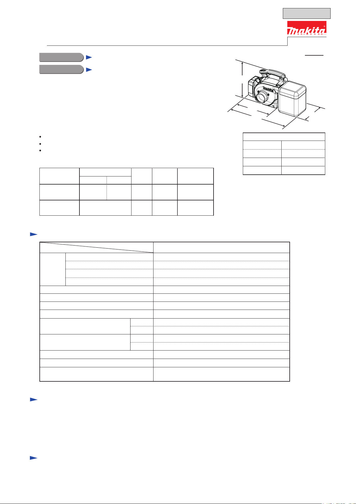
Dimensions*2: mm (")
Length (L
Length (L
Width (W)
Height (H)
*2 With Battery BL1830
*3 L1: without Dust bag assembly
*4 L2: with Dust bag assembly
1*3) 273 (10-3/4)
2*4) 403 (15-7/8)
195 (7-5/8)
226 (8-7/8)
W
The models also include the accessories listed below in "Standard equipment".
Specification
2O)
Model
High
Low
High
Low
Yes (2 settings: High/ Low)
13 (with Battery BL1830)
26 (with Battery BL1830)
Specification
Cell
Battery
Max. air volume: m
Max. air velocity: m/sec
Max. sealed suction: kPa (mmH
Air volume setting
Suction power: W
Continuous run time (approx.)
on a single full battery charge: min.
Dust bag capacity: L
Soft start Yes
Weight according to
EPTA-Procedure 01/2003
*5 With Battery BL1815; without Nozzle assembly, Dust bag assembly, Hose complete
Voltage: V
Capacity: Ah
Charging time (approx.): min.
3/min.
*5: kg (lbs)
BVC350
Li-ion
18V
1.3/ 3.0
15/ 22 with DC18RA
3.4
94
5.5 (560)
50
15
3.0
2.2 (4.8)
Standard equipment
Nozzle assembly ........................................................... 1
Dust bag assembly (cloth) ............................................. 1
Hose complete ø28-2.5 (with Front cuff 22) ............... 1
Front cuff 38 .................................................................. 1
Shoulder belt ................................................................. 1
Note: The standard equipment may vary by country or model variation.
Optional accessories
Battery BL1830
Battery BL1815
Fast charger DC18RA
Charger DC18SD
Charger DC24SC
Automotive charger DC18SE
P 2/ 7
Repair
CAUTION: Repair the machine in accordance with “Instruction manual” or “Safety instructions”.
[1] NECESSARY REPAIRING TOOLS
[2] DISASSEMBLY/ASSEMBLY
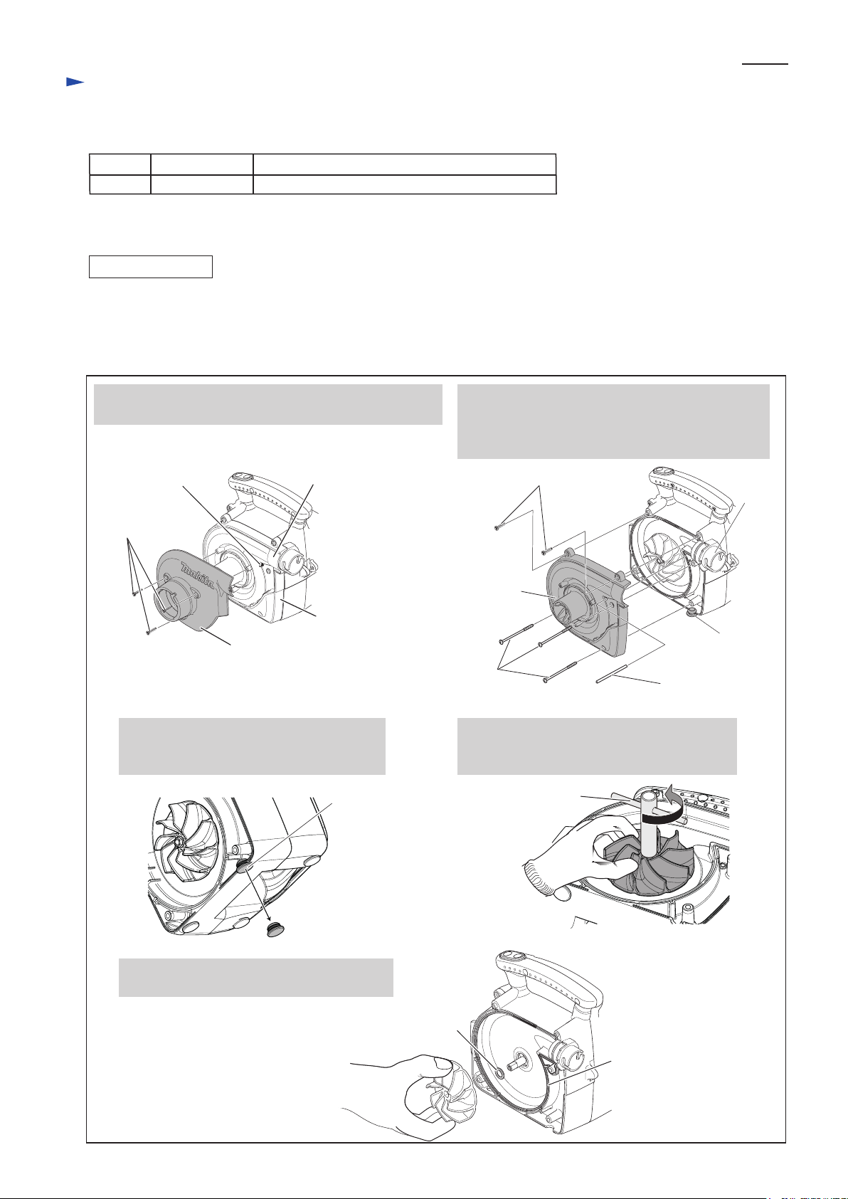
[2]-1. Fan 86
Code No. Description Use for
782209-3 Socket wrench 9 Removing/ tightening M5x10 Hex flange head bolt
DISASSEMBLING
Remove Fan 86 as illustrated in Fig. 1.
Note: 1) Separate Front cover complete from Fan cover first, because there is a 4x75 Tapping screw to fasten Fan cover
under Front cover complete.
2) Blow away the remaining dust in Motor housing set when disassembling it.
4x18 Tapping
screws (3pcs.)
4x18 Tapping screw (2pcs.)
4x75 Tapping
screw (3pcs.)
Front cover complete
1. Remove Front cover complete and 4x18 Tapping screws.
Pin 4 comes into sight as illustrated below.
2. Remove Pin 4, two 4x18 Tapping screws and three
4x75 Tapping screws, and then separate Fan cover
from Motor housing set.
Fan 86 comes into sight.
Pin 4
Note: Do not turn over the machine without removing Pin 4
from Motor housing set.
Fig. 1
Pin 4
Cap 19 hooked with
the notch of Motor
housing set
Cap 19
Joint
Fan cover
Fan 86
Seal ring
Flat washer 10
5. Fan 86 can be removed with Flat washer 10
attached on the reverse.
Motor housing set
Fan cover
Socket wrench 9
Note: Flat washer 10 may fall off Motor shaft,
or may be left on.
Do not miss it.
3. Cap 19 illustrated below is easy to fall off
Motor housing set.
Therefore, remove it in advance.
4. While holding Fan 86 by gloved hand,
remove Max Hex flange head bolt by
turning Socket wrench 9 counterclockwise.
P 3/ 7
Repair
[3] DISASSEMBLY/ASSEMBLY
[3]-1. Fan 86 (cont.)
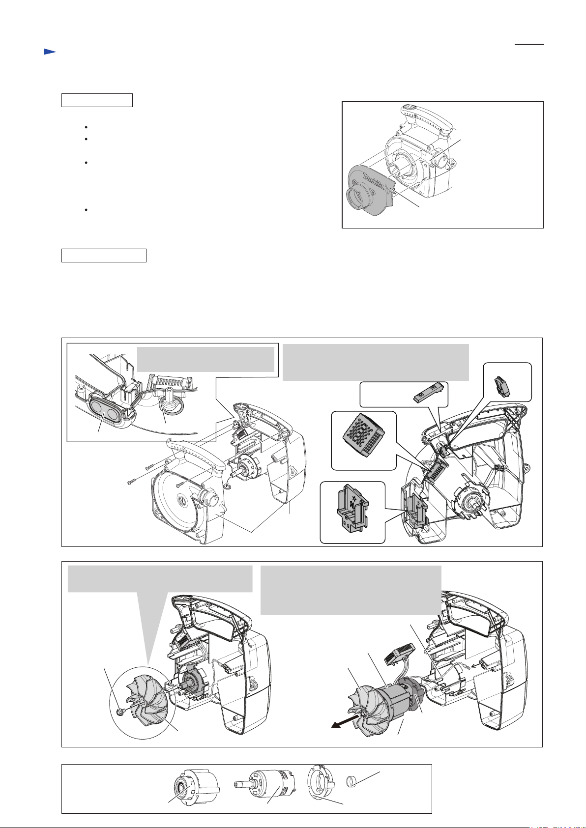
[3]-2. DC Motor, Controller , Switch unit
ASSEMBLING
DISASSEMBLING
Half cylinder shape of
Front cover complete
Fig. 2
Fig. 3
(1) Separate Fan cover from Motor housing set then remove Fan 86 as illustrated in Fig. 1.
(2) Electrical parts can be replaced as illustrated in Fig. 3.
(3) Remove DC motor as illustrated in Fig. 4.
(4) Remove M5x10 Hex flange head bolt and Fan 86 again, and then pull off Motor rubber rings A and B from DC motor.
(Fig. 5)
2. Disconnect Connector.
Switch unit, Controller and Terminal can be
removed.
Switch plate
Motor housing set
Ring
Connector
Switch unit
Terminal
Controller
1. Remove Switch plate and Ring
after removing Fan cover.
Half cylinder shape
of Fan cover
Take the disassembling the step in reverse.
Note: Be sure to put Flat washer 10 in place.
Pass Pin 4 through Fan cover and Motor housing set before
assembling Front cover complete to Fan cover.
Half cylinder shape of Front cover complete must not rise
from that of Fan cover after Fan cover is secured with
three 4x18 Tapping screws. Therefore, tighten their screws
while pushing down the shapes. (Figs. 1 and 2)
Cap 19 mentioned in
after Fan cover is assembled to Front cover complete.
Fig. 1 must be inserted into Housing set
Assemble Fan 86 to Motor shaft provisionally
to remove DC motor from Motor housing set.
Fig. 4
Fig. 5
M5x10 Hex
Flange Head Bolt
Fan 86
Fan 86
Grounding lead wire
Motor rubber ring A
Motor rubber
ring B
Grounding lead wire
Motor rubber ring BDC motor
Cap
Motor rubber ring A with
Ball bearing 6000DDW
Disconnect Grounding lead wire from
Motor housing set, then pull off the Fan 86.
DC motor with Motor rubber rings A and B
can be removed.
 Loading...